EP2962183B1 - Apparatus and method for providing a pan and zoom display for a representation of a process system - Google Patents
Apparatus and method for providing a pan and zoom display for a representation of a process system Download PDFInfo
- Publication number
- EP2962183B1 EP2962183B1 EP14757300.0A EP14757300A EP2962183B1 EP 2962183 B1 EP2962183 B1 EP 2962183B1 EP 14757300 A EP14757300 A EP 14757300A EP 2962183 B1 EP2962183 B1 EP 2962183B1
- Authority
- EP
- European Patent Office
- Prior art keywords
- region
- current view
- process system
- viewport
- representation
- Prior art date
- Legal status (The legal status is an assumption and is not a legal conclusion. Google has not performed a legal analysis and makes no representation as to the accuracy of the status listed.)
- Active
Links
- 238000000034 method Methods 0.000 title claims description 122
- 230000008569 process Effects 0.000 title claims description 98
- 230000000007 visual effect Effects 0.000 claims description 44
- 238000012545 processing Methods 0.000 claims description 24
- 230000004913 activation Effects 0.000 claims description 23
- 238000004519 manufacturing process Methods 0.000 claims description 14
- 238000003860 storage Methods 0.000 claims description 4
- 238000004886 process control Methods 0.000 description 20
- 238000004891 communication Methods 0.000 description 7
- 230000006870 function Effects 0.000 description 6
- 230000008859 change Effects 0.000 description 5
- 238000005259 measurement Methods 0.000 description 5
- 230000003247 decreasing effect Effects 0.000 description 4
- 238000005516 engineering process Methods 0.000 description 4
- 230000015654 memory Effects 0.000 description 4
- 230000004044 response Effects 0.000 description 3
- 230000004075 alteration Effects 0.000 description 2
- 238000004590 computer program Methods 0.000 description 2
- 230000003993 interaction Effects 0.000 description 2
- 239000000463 material Substances 0.000 description 2
- 230000003287 optical effect Effects 0.000 description 2
- 238000010079 rubber tapping Methods 0.000 description 2
- 230000003197 catalytic effect Effects 0.000 description 1
- 239000010779 crude oil Substances 0.000 description 1
- 230000007246 mechanism Effects 0.000 description 1
- 238000012544 monitoring process Methods 0.000 description 1
- 239000003921 oil Substances 0.000 description 1
- 238000004091 panning Methods 0.000 description 1
- 238000012552 review Methods 0.000 description 1
- 239000000126 substance Substances 0.000 description 1
- 238000006467 substitution reaction Methods 0.000 description 1
Images


Classifications
-
- G—PHYSICS
- G09—EDUCATION; CRYPTOGRAPHY; DISPLAY; ADVERTISING; SEALS
- G09G—ARRANGEMENTS OR CIRCUITS FOR CONTROL OF INDICATING DEVICES USING STATIC MEANS TO PRESENT VARIABLE INFORMATION
- G09G5/00—Control arrangements or circuits for visual indicators common to cathode-ray tube indicators and other visual indicators
- G09G5/14—Display of multiple viewports
-
- G—PHYSICS
- G05—CONTROLLING; REGULATING
- G05B—CONTROL OR REGULATING SYSTEMS IN GENERAL; FUNCTIONAL ELEMENTS OF SUCH SYSTEMS; MONITORING OR TESTING ARRANGEMENTS FOR SUCH SYSTEMS OR ELEMENTS
- G05B23/00—Testing or monitoring of control systems or parts thereof
- G05B23/02—Electric testing or monitoring
- G05B23/0205—Electric testing or monitoring by means of a monitoring system capable of detecting and responding to faults
- G05B23/0259—Electric testing or monitoring by means of a monitoring system capable of detecting and responding to faults characterized by the response to fault detection
- G05B23/0267—Fault communication, e.g. human machine interface [HMI]
- G05B23/0272—Presentation of monitored results, e.g. selection of status reports to be displayed; Filtering information to the user
-
- G—PHYSICS
- G06—COMPUTING; CALCULATING OR COUNTING
- G06F—ELECTRIC DIGITAL DATA PROCESSING
- G06F3/00—Input arrangements for transferring data to be processed into a form capable of being handled by the computer; Output arrangements for transferring data from processing unit to output unit, e.g. interface arrangements
- G06F3/01—Input arrangements or combined input and output arrangements for interaction between user and computer
- G06F3/048—Interaction techniques based on graphical user interfaces [GUI]
- G06F3/0484—Interaction techniques based on graphical user interfaces [GUI] for the control of specific functions or operations, e.g. selecting or manipulating an object, an image or a displayed text element, setting a parameter value or selecting a range
-
- G—PHYSICS
- G06—COMPUTING; CALCULATING OR COUNTING
- G06T—IMAGE DATA PROCESSING OR GENERATION, IN GENERAL
- G06T11/00—2D [Two Dimensional] image generation
- G06T11/20—Drawing from basic elements, e.g. lines or circles
- G06T11/206—Drawing of charts or graphs
-
- G—PHYSICS
- G06—COMPUTING; CALCULATING OR COUNTING
- G06T—IMAGE DATA PROCESSING OR GENERATION, IN GENERAL
- G06T11/00—2D [Two Dimensional] image generation
- G06T11/60—Editing figures and text; Combining figures or text
-
- G—PHYSICS
- G06—COMPUTING; CALCULATING OR COUNTING
- G06T—IMAGE DATA PROCESSING OR GENERATION, IN GENERAL
- G06T3/00—Geometric image transformations in the plane of the image
- G06T3/40—Scaling of whole images or parts thereof, e.g. expanding or contracting
-
- G—PHYSICS
- G08—SIGNALLING
- G08B—SIGNALLING OR CALLING SYSTEMS; ORDER TELEGRAPHS; ALARM SYSTEMS
- G08B23/00—Alarms responsive to unspecified undesired or abnormal conditions
-
- G—PHYSICS
- G05—CONTROLLING; REGULATING
- G05B—CONTROL OR REGULATING SYSTEMS IN GENERAL; FUNCTIONAL ELEMENTS OF SUCH SYSTEMS; MONITORING OR TESTING ARRANGEMENTS FOR SUCH SYSTEMS OR ELEMENTS
- G05B2219/00—Program-control systems
- G05B2219/30—Nc systems
- G05B2219/31—From computer integrated manufacturing till monitoring
- G05B2219/31472—Graphical display of process
-
- G—PHYSICS
- G06—COMPUTING; CALCULATING OR COUNTING
- G06F—ELECTRIC DIGITAL DATA PROCESSING
- G06F9/00—Arrangements for program control, e.g. control units
- G06F9/06—Arrangements for program control, e.g. control units using stored programs, i.e. using an internal store of processing equipment to receive or retain programs
- G06F9/44—Arrangements for executing specific programs
- G06F9/451—Execution arrangements for user interfaces
Definitions
- This disclosure relates generally to process control systems and more specifically to an apparatus and method for providing a pan and zoom display for a representation of a process system.
- Processing facilities are often managed using process control systems.
- Example processing facilities include manufacturing plants, chemical plants, crude oil refineries, and ore processing plants.
- process control systems typically manage the use of motors, valves, and other industrial equipment in the processing facilities.
- U.S. Patent Publication No. 2011/0144777 A1 discloses example methods and apparatus to manage process control status rollups.
- a disclosed example method includes receiving process control information from at least one process control device included within a process control system, determining at least one issue associated with a portion of the received process control information, receiving a selection of a status type, determining if the at least one issue is associated with the selected status type, and displaying a process control status rollup associated with the selected status type and including the at least one issue.
- process control systems An important function of process control systems is the ability to provide effective tools for operators to monitor and control industrial processes. These tools often include process schematics that graphically illustrate the industrial processes being controlled. In many cases, the process schematics for a large industrial process are divided into sections, so operators are able to view only smaller portions of the industrial process.
- This disclosure provides an apparatus and method for providing a pan and zoom display for a representation of a process system.
- a method in a first embodiment, includes displaying a plurality of regions in a graphical display. At least two of the regions correspond to different portions of a representation of an industrial process system.
- the regions include a thumbnail region that corresponds to an entirety of the representation of the process system.
- the regions also include a viewport region that corresponds to a portion of the representation of the process system that is less than the entirety of the representation of the process system, where the viewport region is disposed and movable within the thumbnail region.
- the regions further include a current view region that corresponds to a current view of the representation of the process system, where the current view is associated with the viewport region.
- the method also includes, responsive to user activation, moving the viewport region within the thumbnail region and updating the current view region.
- the thumbnail region is configured to identify at least one fault condition indicator outside of the viewport region.
- an apparatus in a second embodiment, includes at least one processing device configured to generate a graphical display having a plurality of regions. At least two of the regions correspond to different portions of a representation of an industrial process system.
- the regions include a thumbnail region that corresponds to an entirety of the representation of the process system.
- the regions also include a viewport region that corresponds to a portion of the representation of the process system that is less than the entirety of the representation of the process system, where the viewport region is disposed and movable within the thumbnail region.
- the regions further include a current view region that corresponds to a current view of the representation of the process system, where the current view is associated with the viewport region.
- the at least one processing device is further configured, responsive to user activation, to move the viewport region within the thumbnail region and to update the current view region.
- the thumbnail region is configured to identify at least one fault condition indicator outside of the viewport region.
- a non-transitory computer readable storage medium includes instructions that, when executed by at least one processing device, cause the at least one processing device to perform the following steps.
- a graphical display having a plurality of regions is generated. At least two of the regions correspond to different portions of a representation of an industrial process system.
- the regions include a thumbnail region that corresponds to an entirety of the representation of the process system.
- the regions also include a viewport region that corresponds to a portion of the representation of the process system that is less than the entirety of the representation of the process system, where the viewport region is disposed and movable within the thumbnail region.
- the regions further include a current view region that corresponds to a current view of the representation of the process system, where the current view is associated with the viewport region. Responsive to user activation, the viewport region is moved within the thumbnail region, and the current view region is updated.
- the thumbnail region is configured to identify at least one fault condition indicator outside of the viewport region.
- FIGURES 1 through 3 discussed below, and the various embodiments used to describe the principles of the present invention in this patent document are by way of illustration only and should not be construed in any way to limit the scope of the invention. Those skilled in the art will understand that the principles of the invention may be implemented in any type of suitably arranged device or system.
- FIGURE 1 illustrates an example process control system 100 according to this disclosure.
- the process control system 100 includes various components that facilitate production or processing of at least one product or other material, such as one or more sensors 102a and one or more actuators 102b.
- the sensors 102a and actuators 102b represent components in a process system that may perform any of a wide variety of functions.
- the sensors 102a could measure a wide variety of characteristics in the process system, such as temperature, pressure, or flow rate.
- the actuators 102b could alter a wide variety of characteristics in the process system, such as heaters, motors, catalytic crackers, or valves.
- the sensors 102a and actuators 102b could represent any other or additional components in any suitable process system.
- Each of the sensors 102a includes any suitable structure for measuring one or more characteristics in a process system.
- Each of the actuators 102b includes any suitable structure for operating on or affecting one or more conditions in a process system.
- a process system may generally represent any system or portion thereof configured to process one or more products or other materials in some manner.
- At least one network 104 is coupled to the sensors 102a and actuators 102b.
- the network 104 facilitates interaction with the sensors 102a and actuators 102b.
- the network 104 could transport measurement data from the sensors 102a and provide control signals to the actuators 102b.
- the network 104 could represent any suitable network or combination of networks.
- the network 104 could represent an Ethernet network, an electrical signal network (such as a HART or FOUNDATION FIELDBUS network), a pneumatic control signal network, or any other or additional type(s) of network(s).
- the controllers 106a-106b are coupled to the network 104.
- the controllers 106a-106b may, among other things, use the measurements from the sensors 102a to control the operation of the actuators 102b.
- the controllers 106a-106b could receive measurement data from the sensors 102a and use the measurement data to generate control signals for the actuators 102b.
- Each of the controllers 106a-106b includes any suitable structure for interacting with the sensors 102a and controlling the actuators 102b.
- the controllers 106a-106b could, for example, represent multivariable controllers or other types of controllers.
- each of the controllers 106a-106b could represent a computing device running a MICROSOFT WINDOWS operating system.
- Two networks 108 are coupled to the controllers 106a-106b.
- the networks 108 facilitate interaction with the controllers 106a-106b, such as by transporting data to and from the controllers 106a-106b.
- the networks 108 could represent any suitable networks or combination of networks.
- the networks 108 could represent a pair of Ethernet networks or a redundant pair of Ethernet networks, such as a FAULT TOLERANT ETHERNET (FTE) network from HONEYWELL INTERNATIONAL INC.
- FTE FAULT TOLERANT ETHERNET
- At least one switch/firewall 110 couples the networks 108 to two networks 112.
- the switch/firewall 110 may transport traffic from one network to another.
- the switch/firewall 110 may also block traffic on one network from reaching another network.
- the switch/firewall 110 includes any suitable structure for providing communication between networks, such as a HONEYWELL CONTROL FIREWALL (CF9) device.
- the networks 112 could represent any suitable networks, such as a pair of Ethernet networks or an FTE network.
- Two servers 114a-114b are coupled to the networks 112.
- the servers 114a-114b perform various functions to support the operation and control of the controllers 106a-106b, sensors 102a, and actuators 102b.
- the servers 114a-114b could log information collected or generated by the controllers 106a-106b, such as measurement data from the sensors 102a or control signals for the actuators 102b.
- the servers 114a-114b could also execute applications that control the operation of the controllers 106a-106b, thereby controlling the operation of the actuators 102b.
- the servers 114a-114b could provide secure access to the controllers 106a-106b.
- Each of the servers 114a-114b includes any suitable structure for providing access to, control of, or operations related to the controllers 106a-106b.
- Each of the servers 114a-114b could, for example, represent a computing device running a MICROSOFT WINDOWS operating system.
- One or more operator stations 116 are coupled to the networks 112.
- the operator stations 116 represent computing or communication devices providing user access to the servers 114a-114b, which could then provide user access to the controllers 106a-106b (and possibly the sensors 102a and actuators 102b).
- the operator stations 116 could allow users to review the operational history of the sensors 102a and actuators 102b using information collected by the controllers 106a-106b and/or the servers 114a-114b.
- the operator stations 116 could also allow the users to adjust the operation of the sensors 102a, actuators 102b, controllers 106a-106b, or servers 114a-114b.
- the operator stations 116 could receive and display warnings, alerts, or other messages or displays generated by the controllers 106a-106b or the servers 114a-114b.
- Each of the operator stations 116 includes any suitable structure for supporting user access and control of the system 100.
- Each of the operator stations 116 could, for example, represent a computing device running a MICROSOFT WINDOWS operating system.
- the system 100 also includes a wireless network 118, which can be used to facilitate communication with one or more wireless devices 120.
- the wireless network 118 may use any suitable technology to communicate, such as radio frequency (RF) signals.
- the wireless devices 120 could represent devices that perform any suitable functions.
- the wireless devices 120 could, for example, represent wireless sensors, wireless actuators, and remote or portable operator stations or other user devices.
- At least one router/firewall 122 couples the networks 112 to two networks 124.
- the router/firewall 122 includes any suitable structure for providing communication between networks, such as a secure router or combination router/firewall.
- the networks 124 could represent any suitable networks, such as a pair of Ethernet networks or an FTE network.
- the system 100 includes at least one additional server 126 coupled to the networks 124.
- the server 126 executes various applications to control the overall operation of the system 100.
- the system 100 could be used in a processing plant or other facility, and the server 126 could execute applications used to control the plant or other facility.
- the server 126 could execute applications such as enterprise resource planning (ERP), manufacturing execution system (MES), or any other or additional plant or process control applications.
- ERP enterprise resource planning
- MES manufacturing execution system
- the server 126 includes any suitable structure for controlling the overall operation of the system 100.
- One or more operator stations 128 are coupled to the networks 124.
- the operator stations 128 represent computing or communication devices providing, for example, user access to the servers 114a-114b, 126.
- Each of the operator stations 128 includes any suitable structure for supporting user access and control of the system 100.
- Each of the operator stations 128 could, for example, represent a computing device running a MICROSOFT WINDOWS operating system.
- each of the servers 114a-114b, 126 could include one or more processors 130 and one or more memories 132 for storing instructions and data used, generated, or collected by the processor(s) 130.
- Each of the servers 114a-114b, 126 could also include at least one network interface 134, such as one or more Ethernet interfaces.
- each of the operator stations 116, 128 could include one or more processors 136 and one or more memories 138 for storing instructions and data used, generated, or collected by the processor(s) 136.
- Each of the operator stations 116, 128 could also include at least one network interface 140, such as one or more Ethernet interfaces.
- the operator stations 116, 128 may include one or more human-machine interface (HMI) applications 142.
- HMI application 142 generally represents an application that generates graphical displays for presenting content to operators. The graphical displays visually represent one or more processes (or portions thereof) being monitored and/or controlled by the operators.
- An HMI application 142 can present any suitable graphical data to an operator, such as a process schematic that graphically illustrates a process to be controlled.
- a user may want to build one large process schematic display to represent a process system, such as an entire industrial process or plant, rather than dividing the representation into many separate displays. This could be due to the large-scale nature of the plant and/or when geography plays an important aspect in a process, such as a large field of wells or a pipeline where operators may prefer to pan along a large pipeline to monitor and control the process.
- the HMI application 142 can generate a graphical display containing a process schematic that graphically illustrates equipment used to perform a particular process. Any other suitable graphical display with other content associated with a process could be presented to an operator.
- the graphical display also includes pan and zoom controls, which allows an operator to zoom in on areas of the displayed process and to pan (move) the zoomed portion of the process. These controls provide for quick and easy navigation between locations within the process when monitoring and/or controlling the process.
- the display can further include a pan and zoom thumbnail that provides a thumbnail overview or an outline of the entire process.
- the thumbnail may include a viewport representation identifying the portion of the process currently being displayed, and the thumbnail can provide situational awareness of a fault condition that occurs outside of the current view. This can be accomplished using a fault condition indicator in the thumbnail, even when the fault occurs outside of the portion of the process currently being viewed.
- FIGURES 2A through 2D An example of a pan and zoom display including a thumbnail is shown in FIGURES 2A through 2D
- Each HMI application 142 includes any suitable application for generating graphical displays representing at least part of a process being monitored and/or controlled.
- the HMI application 142 could use HMIWEB technology from HONEYWELL INTERNATIONAL INC.
- the HMIWEB technology uses hypertext markup language (HTML) and allows users to build process control displays (web pages) that are loaded onto operator stations 116, 128.
- the HTML displays may use INTERNET EXPLORER or other browser technology to extend the functionality of the web pages to allow process information to be displayed and to allow operators to control processes via the web pages.
- the HMI application 142 can operate within a larger system, such as within EXPERION systems from HONEYWELL INTERNATIONAL INC.
- FIGURE 1 illustrates one example of a process control system 100
- a control system could include any number of sensors, actuators, controllers, servers, operator stations, networks, and HMI applications.
- the makeup and arrangement of the process control system 100 in FIGURE 1 is for illustration only. Components could be added, omitted, combined, or placed in any other suitable configuration according to particular needs.
- FIGURE 1 illustrates one operational environment in which pan and zoom control in conjunction with a representation of a process system can be used. This functionality could be used in any other suitable device or system.
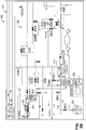
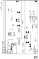
- FIGURES 2A through 2D illustrates an example pan and zoom display 200 for representations of a process system according to this disclosure.
- the pan and zoom display 200 could be generated, for example, by the HMI application 142 in order to present information associated with a process system being controlled by the process control system 100.
- the graphical display 200 illustrated in FIGURES 2A through 2D includes a window 202 rendered by the HMI application 142.
- the window 202 displays a plurality of regions 210, 220, 230, each corresponding to a different portion of a representation of a process system.
- the window 202 may display a thumbnail region 210, a viewport region 220, and a current view region 230.
- the graphical display 200 may also be shown in a windowless mode of operation, such as a full screen display mode.
- the thumbnail region 210 may be a popup display or other display that is generated automatically and that provides a framework for viewing a thumbnail overview of a pan and zoom display.
- the thumbnail region 210 may be repositioned within the window 202, may be placed within a navigation panel 270 (see FIGURE 2D ) within the window 202, and/or may be opened and closed.
- the thumbnail region 210 includes operational data, such as visual indicia 212 of data, and corresponds to an entirety of the representation of the process system.
- the thumbnail region 210 may provide an overview or an outline of an entire process system, such as a large process schematic representative of an entire process or plant.
- the large process schematic may be representative of a large geographically-dispersed system (such as a gas pipeline) or a complex multi-step process (such as a large oil refinery).
- the visual indicia 212 may include text, an image, or a combination thereof.
- the visual indicia 212 may include text and/or a schematic representation of operational data associated with sensors, actuators, other industrial equipment, or any combination thereof.
- the operational data may include data that is associated with the process system, such as sensor data or the like.
- the operational data may include fault condition data
- the visual indicia 212 may include a fault condition indicator, such as an alarm icon 214.
- the viewport region 220 is disposed and moveable within the thumbnail region 210 and corresponds to a portion of the representation of the process system that is less than the entirety of the representation of the process system.
- the viewport region 220 may include visual indicia 222 of data of a type similar to that of the visual indicia 212.
- the visual indicia 222 may be defined by a boundary 224 that encompasses some, but not all, of the visual indicia 212 in the thumbnail region 210.
- the visual indicia 222 within the viewport region 220 may also include fault condition indicators, such as alarm icons 226 and 228. Accordingly, any fault condition indicators that occur may be visible in the thumbnail region 210, which allows an operator to maintain situational awareness of those fault condition indicators (even when a fault occurs outside of the portion of the process currently being viewed).
- the boundary 224 of the viewport region 220 may define a viewable area 225 in the viewport region 220.
- the viewable area 225 of the viewport region 220 includes the visual indicia 222 and is associated with the current view region 230 as described in further detail below.
- the current view region 230 may generally be described as an enlarged view of the viewable area 225, which shows part but not all of the process system.
- the boundary 224 of the viewport region 220 may be moved horizontally and/or vertically within the thumbnail region 210 responsive to user activation of the viewport region 220. As a result, the viewable area 225 within the viewport region 220 can change to display indicia that were previously not in view in the viewable area 225 or only partially in view in the viewable area 225.
- a user may click on the graphical display 200 using a mouse or other pointer and may use a drag and drop method to move the boundary 224 of the viewport region 220.
- on-display controls 250 may be provided, and a user may click the controls 250 or tap on a touchscreen that includes the controls 250 to move the viewport region 220.
- the user may pass a pointer over the viewport region 220, click on another widget, perform a gesture, or use any other suitable input mechanism to move the viewport region 220.
- the viewport region 220 is moveable within the thumbnail region 210, a user may quickly navigate between locations on the representation of the process system within the thumbnail region 210. Movement of the viewport region 220 changes the viewable area 225 and correspondingly changes the current view region 230. This may enable a user to view additional visual indicia, such as portions of the visual indicia 212 within the thumbnail region 210 that are outside of the boundary 224 of the viewport region 220 prior to the movement of the viewport region 220. For example, fault conditions identified by alarm icons that occur outside of the boundary 224 of the viewport region 220 (such as outside the viewable area 225 and correspondingly outside the current view region 230) are visible in the thumbnail region 210. This enables a user to maintain situational awareness of fault conditions, even those outside of the current view region 230.
- the user may quickly move the viewport region 220 within the thumbnail region 210 to another location within the thumbnail region 210, such as to a location of one or more alarm icons that are outside the current boundary 224 of the viewport region 220.
- the one or more alarm icons that were previously outside the boundary 224 may be placed within the boundary 224 of the viewport region 220 (and therefore within both the viewable area 225 and the current view region 230).
- a fault condition causes the alarm icon 214 (which is outside the boundary 224 of the viewport region 220) to become active
- a user may move the viewport region 220 within the thumbnail region 210 so that the alarm icon 214 is within the boundary 224 of the viewport region 220.
- the viewable area 225 of the viewport region 220 will include the alarm icon 214, and the alarm icon 214 will be within the current view region 230. This enables the user to quickly navigate to the alarm icon 214 and to monitor the alarm icon 214 more closely.
- the boundary 224 of the viewport region 220 may be resized (such as enlarged or shrunk) responsive to a second user activation, such as a zoom control.
- the viewable area 225 of the viewport region 220 may be resized in accordance with the resizing of the boundary 224.
- a zoom control may include any suitable amount of zoom. In some embodiments, the amount of zoom may be 50% to 200%. However, the amount of zoom may be different in other implementations.
- the zoom control may also include a proportional zoom (where objects are magnified or shrunk equally) or a semantic zoom (where a level of detail or an entire representation of a resized object is changed to fit into a current size).
- the zoom control may further include a "hyperzoom" feature, which could include a navigation hotspot on the graphical display 200 for linking pan and zoom displays.
- a clickable hyperlink region 260 (shown in FIGURE 2B ) within the graphical display 200 may call up a predefined region or viewport within another pan and zoom display, which allows nesting of pan and zoom displays to effectively extend zoom range.
- a user may activate the hyperlink region 260 by positioning a pointer over the hyperlink region 260 and clicking a mouse, tapping a touchscreen, performing a gesture (such as a swipe gesture or a pinch gesture), engaging a mouse wheel, or providing any other suitable input.
- a user may provide the second user activation by positioning a pointer over the viewport region 220 and clicking a mouse or tapping a touchscreen.
- the user may also click on another widget, perform a gesture (such as a swipe gesture or a pinch gesture), engage a mouse wheel, or click or tap the controls 250 to activate the zoom control.
- the boundary 224 of the viewport region 220 may be resized by an amount that is inversely proportional to the amount of zoom.
- Visual indicia associated with the viewable area 225 of the viewport region 220 and displayed in the current view region 230 may be resized by an amount that is proportional to the amount of zoom as described in further detail below.
- the boundary 224 of the viewport region 220 may be decreased by a factor of two.
- the viewable area 225 of the viewport region 220 may similarly be decreased by a factor of two.
- FIGURE 2C illustrates the pan and zoom display having a user-selected amount of zoom equal to approximately 200%. Both a size of the boundary 224 and a size of the viewable area 225 of the viewport region 220 have been resized (decreased) compared to a size of the boundary 224 and a size of the viewable area 225 of the viewport region 220 at an amount of zoom equal to approximately 100% as shown in FIGURE 2B .
- the boundary 224 of the viewport region 220 may be increased by a factor of two.
- the viewable area 225 of the viewport region 220 may similarly be increased by a factor of two.
- FIGURE 2A illustrates the pan and zoom display having an amount of zoom equal to approximately 50%.
- both a size of the boundary 224 and a size of the viewable area 225 of the viewport region 220 have been resized (increased) compared to a size of the boundary 224 and a size of the viewable area 225 of the viewport region 220 at an amount of zoom equal to approximately 100% as shown in FIGURE 2B .
- the current view region 230 is associated with the viewport region 220 and corresponds to a current view of the representation of the process system.
- the current view region 230 may correspond to the viewable area 225 within the boundary 224 of the viewport region 220 and may include visual indicia 232 of data of a type similar to that of the visual indicia 222.
- the visual indicia 232 shown in the current view region 230 may be an enlarged set of the visual indicia 222 within the viewport region 220.
- the current view region 230 may be updated in response to movement of the viewport region 220. For example, movement of the viewport region 220 causes the viewable area 225 within the viewport region 220 to change.
- the current view region 230 may be updated in correspondence with the change in the viewable area 225 of the viewport region 220 so that the current view region 230 continues to display an enlarged view of the viewable area 225.
- Operational data other than fault condition data, may be subscribed or unsubscribed based on whether the operational data is visible in the current view region 230. For example, assume a user pans (moves) the viewport region 220 within the thumbnail region 210 into a different location of the process system representation. When this occurs, the operational data that is no longer in the current view region 230 may be unsubscribed (other than fault condition data), and the operational data that has come into view in the current view region 230 may be subscribed. This reduces an amount of data processing needed to populate and maintain the graphical display 200.
- the viewport region 220 when the viewport region 220 is moved within the thumbnail region 210, the viewable area 225 changes, and the current view region 230 may be updated in correspondence with the changes in the viewable area 225.
- the process system may only subscribe to operational data that is within the current view region 230. Operational data outside the current view region 230 may be unsubscribed, except for fault condition data.
- the visual indicia 232 of data within the current view region 230 may be resized (such as enlarged or shrunk) responsive to the second user activation (the zoom control). For example, in response to the second user activation of the zoom control associated with the viewport region 220, the visual indicia 232 may be resized by an amount that is proportional to the amount of zoom. To illustrate, if the amount of zoom equals approximately 200%, the visual indicia 232 within the current view region 230 may be increased by an amount that is proportional. For example, FIGURE 2C illustrates the pan and zoom display having a user-selected amount of zoom equal to approximately 200%.
- the visual indicia 232 within the current view region 230 have been resized (increased) as compared to a size of the visual indicia 232 within the current view region 230 at an amount of zoom equal to approximately 100% as shown in FIGURE 2B .
- the visual indicia 232 within the current view region 230 may again be resized by an amount that is proportional.
- FIGURE 2A illustrates a pan and zoom display having an amount of zoom equal to approximately 50%.
- the visual indicia 232 within the current view region 230 have been resized (decreased) as compared to a size of the visual indicia 232 within the current view region 230 at an amount of zoom equal to approximately 100% as shown in FIGURE 2B .
- the second user activation of the viewport region 220 allows a user to zoom in on or out of a particular location of the process system representation. Among other things, this enables a user to monitor a fault condition more closely.
- the current view region 230 may be updated in correspondence with a change in the amount of zoom selected for the viewable area 225 of the viewport region 220.
- the operational data that is no longer in the current view region 230 may be unsubscribed (other than fault condition data), and the operational data that has come into view may be subscribed.
- the viewport region 220 is activated via the zoom control, the viewable area 225 changes, and the current view region 230 may be updated in correspondence with the changes in the viewable area 225.
- the process system may only subscribe to operational data that is within the current view region 230. Operational data outside the current view region 230 may be unsubscribed, except for fault condition data.
- FIGURES 2A through 2D illustrate an example of a pan and zoom display 200 for representations of a process system
- various changes may be made to FIGURES 2A through 2D .
- the process system shown here is for illustration only, and any other suitable process system can be displayed.
- the positions of certain features, such as the relative positions of the regions 210 and 230 and the controls 250, can be changed.
- FIGURE 3 illustrates an example method 300 for providing a pan and zoom display for a representation of a process system according to this disclosure.
- the method 300 could, for example, be used by the HMI application 142 in the process control system 100 of FIGURE 1 .
- a plurality of regions may be displayed, where each region corresponds to a different portion of a representation of a process system, at step 302.
- the HMI application 142 of FIGURE 1 may generate the graphical display 200 of FIGURES 2A through 2D , which can be displayed at any of the operator stations 116, 128 of FIGURE 1 .
- a thumbnail region that corresponds to an entirety of the representation of the process system is displayed at 304.
- the thumbnail region 210 of FIGURES 2A through 2D may be displayed at any of the operator stations 116, 128 of FIGURE 1 .
- a viewport region that corresponds to a portion of the representation of the process system that is less than the entirety of the representation of the process system is displayed at step 306.
- the viewport region is disposed and movable within the thumbnail region.
- the viewport region 220 of FIGURES 2A through 2D may be displayed at any of the operator stations 116, 128 of FIGURE 1 .
- a current view region that corresponds to a current view of the representation of the process system is displayed at step 308.
- the current view is associated with the viewport region.
- the current view region 230 of FIGURES 2A through 2D may be displayed at any of the operator stations 116, 128 of FIGURE 1 .
- the current view may correspond to an enlarged view of the viewable area 225 of the viewport region 220 of FIGURES 2A through 2D .
- Visual indicia of data corresponding to the representation of the process system disposed within the thumbnail region, the viewport region, and the current view region are displayed at step 310.
- a portion of the visual indicia 212 of FIGURE 2A may be disposed within the thumbnail region 210 of FIGURES 2A through 2D and may be displayed at the operator stations 116, 128 of FIGURE 1 .
- a portion of the visual indicia 222 of FIGURE 2A may be disposed within the viewport region 220 of FIGURES 2A through 2D and may be displayed at the operator stations 116, 128 of FIGURE 1 .
- a portion of the visual indicia 232 of FIGURE 2A may be disposed within the current view region 230 of FIGURES 2A through 2D and may be displayed at the operator stations 116, 128 of FIGURE 1 .
- the viewport region may be moved within the thumbnail region responsive to user activation, where the thumbnail region enables a user to maintain situational awareness of a change in visual indicia of data that occurs outside of the current view region, at step 312.
- the viewport region 220 of FIGURES 2A through 2D may be moved within the thumbnail region 210 responsive to a drag and drop method to move the boundary 224 of the viewport region 220.
- the viewport region 220 may be moved via the controls 250, or the user may pass a pointer over the viewport region 220, click on another widget, or perform a gesture (such as a swipe or a pinch) to move the viewport region 220 within the thumbnail region 210.
- FIGURE 3 illustrates one example of a method 300 for providing a pan and zoom display for a representation of a process system
- various changes may be made to FIGURE 3 .
- steps shown in FIGURE 3 could overlap, occur in parallel, occur in a different order, or occur multiple times.
- some steps could be combined or removed and additional steps could be added according to particular needs.
- various functions described above are implemented or supported by a computer program that is formed from computer readable program code and that is embodied in a computer readable medium.
- computer readable program code includes any type of computer code, including source code, object code, and executable code.
- computer readable medium includes any type of medium capable of being accessed by a computer, such as read only memory (ROM), random access memory (RAM), a hard disk drive, a compact disc (CD), a digital video disc (DVD), or any other type of memory.
- ROM read only memory
- RAM random access memory
- CD compact disc
- DVD digital video disc
- a “non-transitory” computer readable medium excludes wired, wireless, optical, or other communication links that transport transitory electrical or other signals.
- a non-transitory computer readable medium includes media where data can be permanently stored and media where data can be stored and later overwritten, such as a rewritable optical disc or an erasable memory device.
- application and “program” refer to one or more computer programs, software components, sets of instructions, procedures, functions, objects, classes, instances, related data, or a portion thereof adapted for implementation in a suitable computer code (including source code, object code, or executable code).
- suitable computer code including source code, object code, or executable code.
- transmit encompass both direct and indirect communication.
- the term “or” is inclusive, meaning and/or.
- controller means any device, system, or part thereof that controls at least one operation.
- a controller may be implemented in hardware or a combination of hardware and software/firmware. The functionality associated with any particular controller may be centralized or distributed, whether locally or remotely.
- phrases "at least one of,” when used with a list of items, means that different combinations of one or more of the listed items may be used, and only one item in the list may be needed.
- “at least one of: A, B, and C” includes any of the following combinations: A, B, C, A and B, A and C, B and C, and A and B and C.
Landscapes
- Engineering & Computer Science (AREA)
- Physics & Mathematics (AREA)
- General Physics & Mathematics (AREA)
- Theoretical Computer Science (AREA)
- Human Computer Interaction (AREA)
- General Engineering & Computer Science (AREA)
- Computer Hardware Design (AREA)
- Automation & Control Theory (AREA)
- Business, Economics & Management (AREA)
- Emergency Management (AREA)
- User Interface Of Digital Computer (AREA)
- Testing And Monitoring For Control Systems (AREA)
Applications Claiming Priority (2)
| Application Number | Priority Date | Filing Date | Title |
|---|---|---|---|
| US13/779,154 US9240164B2 (en) | 2013-02-27 | 2013-02-27 | Apparatus and method for providing a pan and zoom display for a representation of a process system |
| PCT/US2014/015502 WO2014133735A1 (en) | 2013-02-27 | 2014-02-10 | Apparatus and method for providing a pan and zoom display for a representation of a process system |
Publications (3)
| Publication Number | Publication Date |
|---|---|
| EP2962183A1 EP2962183A1 (en) | 2016-01-06 |
| EP2962183A4 EP2962183A4 (en) | 2016-10-26 |
| EP2962183B1 true EP2962183B1 (en) | 2019-08-07 |
Family
ID=51387682
Family Applications (1)
| Application Number | Title | Priority Date | Filing Date |
|---|---|---|---|
| EP14757300.0A Active EP2962183B1 (en) | 2013-02-27 | 2014-02-10 | Apparatus and method for providing a pan and zoom display for a representation of a process system |
Country Status (6)
| Country | Link |
|---|---|
| US (1) | US9240164B2 (zh) |
| EP (1) | EP2962183B1 (zh) |
| CN (1) | CN105122205B (zh) |
| AU (1) | AU2014221336B2 (zh) |
| CA (1) | CA2902024C (zh) |
| WO (1) | WO2014133735A1 (zh) |
Families Citing this family (20)
| Publication number | Priority date | Publication date | Assignee | Title |
|---|---|---|---|---|
| US9383890B2 (en) * | 2013-03-14 | 2016-07-05 | General Electric Company | Semantic zoom of graphical visualizations in industrial HMI systems |
| US10474240B2 (en) * | 2013-06-10 | 2019-11-12 | Honeywell International Inc. | Frameworks, devices and methods configured for enabling gesture-based interaction between a touch/gesture controlled display and other networked devices |
| US20160292895A1 (en) * | 2015-03-31 | 2016-10-06 | Rockwell Automation Technologies, Inc. | Layered map presentation for industrial data |
| US10528021B2 (en) | 2015-10-30 | 2020-01-07 | Rockwell Automation Technologies, Inc. | Automated creation of industrial dashboards and widgets |
| US10313281B2 (en) | 2016-01-04 | 2019-06-04 | Rockwell Automation Technologies, Inc. | Delivery of automated notifications by an industrial asset |
| US10761706B2 (en) | 2016-05-04 | 2020-09-01 | Honeywell International Inc. | Navigating an operational user interface for a building management system |
| US10121515B2 (en) | 2016-06-06 | 2018-11-06 | Avigilon Corporation | Method, system and computer program product for interactively identifying same individuals or objects present in video recordings |
| US10318570B2 (en) | 2016-08-18 | 2019-06-11 | Rockwell Automation Technologies, Inc. | Multimodal search input for an industrial search platform |
| EP3299911A1 (en) * | 2016-09-22 | 2018-03-28 | Siemens Aktiengesellschaft | Method and system for dynamically monitoring and controlling an industrial plant |
| US10319128B2 (en) | 2016-09-26 | 2019-06-11 | Rockwell Automation Technologies, Inc. | Augmented reality presentation of an industrial environment |
| US10401839B2 (en) | 2016-09-26 | 2019-09-03 | Rockwell Automation Technologies, Inc. | Workflow tracking and identification using an industrial monitoring system |
| US10545492B2 (en) | 2016-09-26 | 2020-01-28 | Rockwell Automation Technologies, Inc. | Selective online and offline access to searchable industrial automation data |
| US10735691B2 (en) | 2016-11-08 | 2020-08-04 | Rockwell Automation Technologies, Inc. | Virtual reality and augmented reality for industrial automation |
| US10388075B2 (en) | 2016-11-08 | 2019-08-20 | Rockwell Automation Technologies, Inc. | Virtual reality and augmented reality for industrial automation |
| US10866631B2 (en) | 2016-11-09 | 2020-12-15 | Rockwell Automation Technologies, Inc. | Methods, systems, apparatuses, and techniques for employing augmented reality and virtual reality |
| KR101873655B1 (ko) * | 2016-11-30 | 2018-07-02 | 엘에스산전 주식회사 | 모니터링 화면 표시 방법 |
| WO2018181598A1 (ja) * | 2017-03-28 | 2018-10-04 | 東芝エネルギーシステムズ株式会社 | 監視システム、画像情報提供装置、クライアント制御装置、画像情報提供プログラム、及びクライアント制御プログラム |
| US10445944B2 (en) | 2017-11-13 | 2019-10-15 | Rockwell Automation Technologies, Inc. | Augmented reality safety automation zone system and method |
| US11249628B2 (en) * | 2019-09-17 | 2022-02-15 | Fisher-Rosemount Systems, Inc. | Graphical user interface (GUI) systems and methods for refactoring full-size process plant displays at various zoom and detail levels for visualization on mobile user interface devices |
| US11507251B2 (en) * | 2019-09-17 | 2022-11-22 | Fisher-Rosemount Systems, Inc. | Guided user interface (GUI) based systems and methods for regionizing full-size process plant displays for rendering on mobile user interface devices |
Family Cites Families (46)
| Publication number | Priority date | Publication date | Assignee | Title |
|---|---|---|---|---|
| US5428733A (en) | 1991-12-16 | 1995-06-27 | Apple Computer, Inc. | Method of calculating dimensions and positioning of rectangular balloons |
| US5896138A (en) | 1992-10-05 | 1999-04-20 | Fisher Controls International, Inc. | Process control with graphical attribute interface |
| US5631825A (en) | 1993-09-29 | 1997-05-20 | Dow Benelux N.V. | Operator station for manufacturing process control system |
| US5576946A (en) | 1993-09-30 | 1996-11-19 | Fluid Air, Inc. | Icon based process design and control system |
| JP3211663B2 (ja) | 1996-05-20 | 2001-09-25 | 株式会社日立製作所 | プラント運転情報表示方法及びプラント運転監視装置 |
| US6760048B1 (en) | 1999-06-15 | 2004-07-06 | International Business Machines Corporation | Display of occluded display elements on a computer display |
| US6901560B1 (en) | 1999-07-01 | 2005-05-31 | Honeywell Inc. | Process variable generalized graphical device display and methods regarding same |
| US6473660B1 (en) | 1999-12-03 | 2002-10-29 | The Foxboro Company | Process control system and method with automatic fault avoidance |
| US7249326B2 (en) | 2000-04-06 | 2007-07-24 | Microsoft Corporation | Method and system for reducing notification area clutter |
| US7613716B2 (en) | 2001-07-20 | 2009-11-03 | The Mathworks, Inc. | Partitioning for model-based design |
| US7024626B2 (en) | 2001-11-30 | 2006-04-04 | Apple Computer, Inc. | System and method of producing user interface information messages |
| US7778717B2 (en) | 2002-04-15 | 2010-08-17 | Invensys Systems, Inc. | Component object model communication method for a control system |
| AU2003294218A1 (en) | 2002-08-28 | 2004-04-23 | Arizona Board Of Regents | Steering logic for control moment gyro system |
| US8068990B2 (en) | 2003-03-25 | 2011-11-29 | Hologic, Inc. | Diagnosis of intra-uterine infection by proteomic analysis of cervical-vaginal fluids |
| US7827120B1 (en) * | 2004-02-19 | 2010-11-02 | Celeritasworks Llc | Community awareness management systems and methods |
| JP2007536634A (ja) | 2004-05-04 | 2007-12-13 | フィッシャー−ローズマウント・システムズ・インコーポレーテッド | プロセス制御システムのためのサービス指向型アーキテクチャ |
| JP4347779B2 (ja) | 2004-10-14 | 2009-10-21 | 富士フイルム株式会社 | 電子アルバム表示システム、電子アルバム表示方法、リモートコントローラ、及びリモートコントロールプログラム |
| US7925985B2 (en) * | 2005-07-29 | 2011-04-12 | Sap Ag | Methods and apparatus for process thumbnail view |
| CN100458778C (zh) * | 2005-09-30 | 2009-02-04 | 腾讯科技(深圳)有限公司 | 图片搜索方法及其装置 |
| US7707516B2 (en) | 2006-05-26 | 2010-04-27 | Google Inc. | Embedded navigation interface |
| KR100834813B1 (ko) | 2006-09-26 | 2008-06-05 | 삼성전자주식회사 | 휴대용 단말기의 멀티미디어 컨텐트 관리 장치 및 방법 |
| JP4912117B2 (ja) | 2006-10-27 | 2012-04-11 | 三洋電機株式会社 | 追跡機能付き撮像装置 |
| JP4270269B2 (ja) | 2006-11-30 | 2009-05-27 | ブラザー工業株式会社 | 通信システム、印刷装置、ユーザ端末装置及びプログラム |
| US10783526B2 (en) * | 2006-12-19 | 2020-09-22 | Celeritasworks, Llc | Campaign awareness management systems and methods |
| EP1965301A1 (en) * | 2007-02-27 | 2008-09-03 | Abb Research Ltd. | Method and system for generating a control system user interface |
| US8108790B2 (en) | 2007-03-26 | 2012-01-31 | Honeywell International Inc. | Apparatus and method for visualization of control techniques in a process control system |
| US7843451B2 (en) * | 2007-05-25 | 2010-11-30 | Google Inc. | Efficient rendering of panoramic images, and applications thereof |
| US7831411B2 (en) | 2007-05-25 | 2010-11-09 | Rockwell Automation Technologies, Inc. | Diagnostic tool for retroactive assessment of industrial process performance |
| CN101251872A (zh) * | 2007-06-29 | 2008-08-27 | 深圳市海云天科技有限公司 | 一种实现试卷与缩略图同步移动的阅卷系统及其方法 |
| US20090030758A1 (en) * | 2007-07-26 | 2009-01-29 | Gennaro Castelli | Methods for assessing potentially compromising situations of a utility company |
| CN101772742B (zh) * | 2007-08-08 | 2013-09-11 | Abb公司 | 用于提供与来自过程控制系统的告警有关的统计的告警分析系统和方法 |
| US20090132954A1 (en) | 2007-11-20 | 2009-05-21 | Honeywell International Inc. | Apparatus and method for isolating problems in content loaded into a human-machine interface application |
| JP5035066B2 (ja) | 2008-03-27 | 2012-09-26 | 富士通株式会社 | 表示位置決定プログラム、該プログラムを記録した記録媒体、表示位置決定装置および表示位置決定方法 |
| US20090300692A1 (en) | 2008-06-02 | 2009-12-03 | Mavlankar Aditya A | Systems and methods for video streaming and display |
| US8103367B2 (en) * | 2008-11-20 | 2012-01-24 | Fisher-Rosemount Systems, Inc. | Methods and apparatus to draw attention to information presented via electronic displays to process plant operators |
| EP2422252B1 (en) * | 2009-04-22 | 2019-10-09 | ABB Schweiz AG | Supervisory control system, method and computer program products |
| US8830267B2 (en) | 2009-11-16 | 2014-09-09 | Alliance For Sustainable Energy, Llc | Augmented reality building operations tool |
| US9557735B2 (en) * | 2009-12-10 | 2017-01-31 | Fisher-Rosemount Systems, Inc. | Methods and apparatus to manage process control status rollups |
| US8860728B2 (en) | 2010-04-05 | 2014-10-14 | Honeywell International Inc. | Apparatus and method for providing and positioning additional context for a process variable in a graphical display of an industrial human machine interface |
| US9024955B2 (en) * | 2010-04-14 | 2015-05-05 | Yokogawa Electric Corporation | Method and system for displaying proiritized live thumbnail of process graphic views |
| US8589814B2 (en) | 2010-04-16 | 2013-11-19 | Honeywell International Inc. | System and method for visual presentation of information in a process control system |
| US10645344B2 (en) | 2010-09-10 | 2020-05-05 | Avigilion Analytics Corporation | Video system with intelligent visual display |
| GB2493551A (en) * | 2011-08-11 | 2013-02-13 | Dexdyne Ltd | Displaying plotted trend data at varying resolutions |
| WO2013123991A1 (en) * | 2012-02-23 | 2013-08-29 | Abb Research Ltd | A method for providing a navigation tool of a user interface for an industrial control system |
| CN104246632A (zh) * | 2012-03-08 | 2014-12-24 | Abb技术有限公司 | 用于在一个显示中对工业设施的装置数据和网络进行可视化的系统及方法 |
| US20130321461A1 (en) * | 2012-05-29 | 2013-12-05 | Google Inc. | Method and System for Navigation to Interior View Imagery from Street Level Imagery |
-
2013
- 2013-02-27 US US13/779,154 patent/US9240164B2/en active Active
-
2014
- 2014-02-10 CN CN201480023556.0A patent/CN105122205B/zh active Active
- 2014-02-10 WO PCT/US2014/015502 patent/WO2014133735A1/en active Application Filing
- 2014-02-10 CA CA2902024A patent/CA2902024C/en active Active
- 2014-02-10 AU AU2014221336A patent/AU2014221336B2/en active Active
- 2014-02-10 EP EP14757300.0A patent/EP2962183B1/en active Active
Non-Patent Citations (1)
| Title |
|---|
| None * |
Also Published As
| Publication number | Publication date |
|---|---|
| EP2962183A4 (en) | 2016-10-26 |
| AU2014221336A1 (en) | 2015-09-17 |
| CN105122205B (zh) | 2018-09-18 |
| CA2902024C (en) | 2022-03-15 |
| US9240164B2 (en) | 2016-01-19 |
| US20140240356A1 (en) | 2014-08-28 |
| CA2902024A1 (en) | 2014-09-04 |
| WO2014133735A1 (en) | 2014-09-04 |
| AU2014221336B2 (en) | 2019-10-03 |
| CN105122205A (zh) | 2015-12-02 |
| EP2962183A1 (en) | 2016-01-06 |
Similar Documents
| Publication | Publication Date | Title |
|---|---|---|
| EP2962183B1 (en) | Apparatus and method for providing a pan and zoom display for a representation of a process system | |
| AU2018288650B2 (en) | Augmented reality user interface on mobile device for presentation of information related to industrial process, control and automation system, or other system | |
| EP2972724B1 (en) | Apparatus and method for managing open windows in a graphical display for a representation of a process system | |
| US9760074B2 (en) | Visualization employing heat maps to convey quality, prognostics, or diagnostics information | |
| US8589814B2 (en) | System and method for visual presentation of information in a process control system | |
| WO2008118891A2 (en) | Apparatus and method for visualization of control techniques in a process control system | |
| EP2503419B1 (en) | Manipulation monitoring device and manipulation monitoring method | |
| US8860728B2 (en) | Apparatus and method for providing and positioning additional context for a process variable in a graphical display of an industrial human machine interface | |
| US8001480B2 (en) | Apparatus and method for defining and controlling graphical faceplates in a process control system | |
| US10579217B2 (en) | System and method for presenting a customizable graphical view of a system status to identify system failures | |
| EP2212819A1 (en) | Apparatus and method for isolating problems in content loaded into a human-machine interface application | |
| JP6405266B2 (ja) | グラフ表示装置、グラフ表示方法、およびプログラム | |
| EP2859435A1 (en) | Context based desktop environment for controlling physical systems |
Legal Events
| Date | Code | Title | Description |
|---|---|---|---|
| PUAI | Public reference made under article 153(3) epc to a published international application that has entered the european phase |
Free format text: ORIGINAL CODE: 0009012 |
|
| 17P | Request for examination filed |
Effective date: 20150818 |
|
| AK | Designated contracting states |
Kind code of ref document: A1 Designated state(s): AL AT BE BG CH CY CZ DE DK EE ES FI FR GB GR HR HU IE IS IT LI LT LU LV MC MK MT NL NO PL PT RO RS SE SI SK SM TR |
|
| AX | Request for extension of the european patent |
Extension state: BA ME |
|
| DAX | Request for extension of the european patent (deleted) | ||
| A4 | Supplementary search report drawn up and despatched |
Effective date: 20160927 |
|
| RIC1 | Information provided on ipc code assigned before grant |
Ipc: G06F 3/14 20060101AFI20160921BHEP Ipc: G05B 23/02 20060101ALI20160921BHEP Ipc: G06F 3/048 20060101ALI20160921BHEP |
|
| STAA | Information on the status of an ep patent application or granted ep patent |
Free format text: STATUS: EXAMINATION IS IN PROGRESS |
|
| 17Q | First examination report despatched |
Effective date: 20180323 |
|
| GRAP | Despatch of communication of intention to grant a patent |
Free format text: ORIGINAL CODE: EPIDOSNIGR1 |
|
| STAA | Information on the status of an ep patent application or granted ep patent |
Free format text: STATUS: GRANT OF PATENT IS INTENDED |
|
| INTG | Intention to grant announced |
Effective date: 20190320 |
|
| GRAS | Grant fee paid |
Free format text: ORIGINAL CODE: EPIDOSNIGR3 |
|
| GRAA | (expected) grant |
Free format text: ORIGINAL CODE: 0009210 |
|
| STAA | Information on the status of an ep patent application or granted ep patent |
Free format text: STATUS: THE PATENT HAS BEEN GRANTED |
|
| AK | Designated contracting states |
Kind code of ref document: B1 Designated state(s): AL AT BE BG CH CY CZ DE DK EE ES FI FR GB GR HR HU IE IS IT LI LT LU LV MC MK MT NL NO PL PT RO RS SE SI SK SM TR |
|
| REG | Reference to a national code |
Ref country code: GB Ref legal event code: FG4D |
|
| REG | Reference to a national code |
Ref country code: CH Ref legal event code: EP Ref country code: AT Ref legal event code: REF Ref document number: 1164870 Country of ref document: AT Kind code of ref document: T Effective date: 20190815 |
|
| REG | Reference to a national code |
Ref country code: DE Ref legal event code: R096 Ref document number: 602014051333 Country of ref document: DE |
|
| REG | Reference to a national code |
Ref country code: IE Ref legal event code: FG4D |
|
| REG | Reference to a national code |
Ref country code: NL Ref legal event code: MP Effective date: 20190807 |
|
| REG | Reference to a national code |
Ref country code: LT Ref legal event code: MG4D |
|
| PG25 | Lapsed in a contracting state [announced via postgrant information from national office to epo] |
Ref country code: PT Free format text: LAPSE BECAUSE OF FAILURE TO SUBMIT A TRANSLATION OF THE DESCRIPTION OR TO PAY THE FEE WITHIN THE PRESCRIBED TIME-LIMIT Effective date: 20191209 Ref country code: SE Free format text: LAPSE BECAUSE OF FAILURE TO SUBMIT A TRANSLATION OF THE DESCRIPTION OR TO PAY THE FEE WITHIN THE PRESCRIBED TIME-LIMIT Effective date: 20190807 Ref country code: HR Free format text: LAPSE BECAUSE OF FAILURE TO SUBMIT A TRANSLATION OF THE DESCRIPTION OR TO PAY THE FEE WITHIN THE PRESCRIBED TIME-LIMIT Effective date: 20190807 Ref country code: LT Free format text: LAPSE BECAUSE OF FAILURE TO SUBMIT A TRANSLATION OF THE DESCRIPTION OR TO PAY THE FEE WITHIN THE PRESCRIBED TIME-LIMIT Effective date: 20190807 Ref country code: FI Free format text: LAPSE BECAUSE OF FAILURE TO SUBMIT A TRANSLATION OF THE DESCRIPTION OR TO PAY THE FEE WITHIN THE PRESCRIBED TIME-LIMIT Effective date: 20190807 Ref country code: BG Free format text: LAPSE BECAUSE OF FAILURE TO SUBMIT A TRANSLATION OF THE DESCRIPTION OR TO PAY THE FEE WITHIN THE PRESCRIBED TIME-LIMIT Effective date: 20191107 Ref country code: NL Free format text: LAPSE BECAUSE OF FAILURE TO SUBMIT A TRANSLATION OF THE DESCRIPTION OR TO PAY THE FEE WITHIN THE PRESCRIBED TIME-LIMIT Effective date: 20190807 Ref country code: NO Free format text: LAPSE BECAUSE OF FAILURE TO SUBMIT A TRANSLATION OF THE DESCRIPTION OR TO PAY THE FEE WITHIN THE PRESCRIBED TIME-LIMIT Effective date: 20191107 |
|
| REG | Reference to a national code |
Ref country code: AT Ref legal event code: MK05 Ref document number: 1164870 Country of ref document: AT Kind code of ref document: T Effective date: 20190807 |
|
| PG25 | Lapsed in a contracting state [announced via postgrant information from national office to epo] |
Ref country code: AL Free format text: LAPSE BECAUSE OF FAILURE TO SUBMIT A TRANSLATION OF THE DESCRIPTION OR TO PAY THE FEE WITHIN THE PRESCRIBED TIME-LIMIT Effective date: 20190807 Ref country code: ES Free format text: LAPSE BECAUSE OF FAILURE TO SUBMIT A TRANSLATION OF THE DESCRIPTION OR TO PAY THE FEE WITHIN THE PRESCRIBED TIME-LIMIT Effective date: 20190807 Ref country code: IS Free format text: LAPSE BECAUSE OF FAILURE TO SUBMIT A TRANSLATION OF THE DESCRIPTION OR TO PAY THE FEE WITHIN THE PRESCRIBED TIME-LIMIT Effective date: 20191207 Ref country code: LV Free format text: LAPSE BECAUSE OF FAILURE TO SUBMIT A TRANSLATION OF THE DESCRIPTION OR TO PAY THE FEE WITHIN THE PRESCRIBED TIME-LIMIT Effective date: 20190807 Ref country code: RS Free format text: LAPSE BECAUSE OF FAILURE TO SUBMIT A TRANSLATION OF THE DESCRIPTION OR TO PAY THE FEE WITHIN THE PRESCRIBED TIME-LIMIT Effective date: 20190807 Ref country code: GR Free format text: LAPSE BECAUSE OF FAILURE TO SUBMIT A TRANSLATION OF THE DESCRIPTION OR TO PAY THE FEE WITHIN THE PRESCRIBED TIME-LIMIT Effective date: 20191108 |
|
| PG25 | Lapsed in a contracting state [announced via postgrant information from national office to epo] |
Ref country code: TR Free format text: LAPSE BECAUSE OF FAILURE TO SUBMIT A TRANSLATION OF THE DESCRIPTION OR TO PAY THE FEE WITHIN THE PRESCRIBED TIME-LIMIT Effective date: 20190807 |
|
| PG25 | Lapsed in a contracting state [announced via postgrant information from national office to epo] |
Ref country code: IT Free format text: LAPSE BECAUSE OF FAILURE TO SUBMIT A TRANSLATION OF THE DESCRIPTION OR TO PAY THE FEE WITHIN THE PRESCRIBED TIME-LIMIT Effective date: 20190807 Ref country code: RO Free format text: LAPSE BECAUSE OF FAILURE TO SUBMIT A TRANSLATION OF THE DESCRIPTION OR TO PAY THE FEE WITHIN THE PRESCRIBED TIME-LIMIT Effective date: 20190807 Ref country code: DK Free format text: LAPSE BECAUSE OF FAILURE TO SUBMIT A TRANSLATION OF THE DESCRIPTION OR TO PAY THE FEE WITHIN THE PRESCRIBED TIME-LIMIT Effective date: 20190807 Ref country code: AT Free format text: LAPSE BECAUSE OF FAILURE TO SUBMIT A TRANSLATION OF THE DESCRIPTION OR TO PAY THE FEE WITHIN THE PRESCRIBED TIME-LIMIT Effective date: 20190807 Ref country code: EE Free format text: LAPSE BECAUSE OF FAILURE TO SUBMIT A TRANSLATION OF THE DESCRIPTION OR TO PAY THE FEE WITHIN THE PRESCRIBED TIME-LIMIT Effective date: 20190807 Ref country code: PL Free format text: LAPSE BECAUSE OF FAILURE TO SUBMIT A TRANSLATION OF THE DESCRIPTION OR TO PAY THE FEE WITHIN THE PRESCRIBED TIME-LIMIT Effective date: 20190807 |
|
| PG25 | Lapsed in a contracting state [announced via postgrant information from national office to epo] |
Ref country code: SM Free format text: LAPSE BECAUSE OF FAILURE TO SUBMIT A TRANSLATION OF THE DESCRIPTION OR TO PAY THE FEE WITHIN THE PRESCRIBED TIME-LIMIT Effective date: 20190807 Ref country code: SK Free format text: LAPSE BECAUSE OF FAILURE TO SUBMIT A TRANSLATION OF THE DESCRIPTION OR TO PAY THE FEE WITHIN THE PRESCRIBED TIME-LIMIT Effective date: 20190807 Ref country code: IS Free format text: LAPSE BECAUSE OF FAILURE TO SUBMIT A TRANSLATION OF THE DESCRIPTION OR TO PAY THE FEE WITHIN THE PRESCRIBED TIME-LIMIT Effective date: 20200224 Ref country code: CZ Free format text: LAPSE BECAUSE OF FAILURE TO SUBMIT A TRANSLATION OF THE DESCRIPTION OR TO PAY THE FEE WITHIN THE PRESCRIBED TIME-LIMIT Effective date: 20190807 |
|
| REG | Reference to a national code |
Ref country code: DE Ref legal event code: R097 Ref document number: 602014051333 Country of ref document: DE |
|
| PLBE | No opposition filed within time limit |
Free format text: ORIGINAL CODE: 0009261 |
|
| STAA | Information on the status of an ep patent application or granted ep patent |
Free format text: STATUS: NO OPPOSITION FILED WITHIN TIME LIMIT |
|
| PG2D | Information on lapse in contracting state deleted |
Ref country code: IS |
|
| 26N | No opposition filed |
Effective date: 20200603 |
|
| PG25 | Lapsed in a contracting state [announced via postgrant information from national office to epo] |
Ref country code: SI Free format text: LAPSE BECAUSE OF FAILURE TO SUBMIT A TRANSLATION OF THE DESCRIPTION OR TO PAY THE FEE WITHIN THE PRESCRIBED TIME-LIMIT Effective date: 20190807 |
|
| REG | Reference to a national code |
Ref country code: CH Ref legal event code: PL |
|
| REG | Reference to a national code |
Ref country code: BE Ref legal event code: MM Effective date: 20200229 |
|
| PG25 | Lapsed in a contracting state [announced via postgrant information from national office to epo] |
Ref country code: LU Free format text: LAPSE BECAUSE OF NON-PAYMENT OF DUE FEES Effective date: 20200210 Ref country code: MC Free format text: LAPSE BECAUSE OF FAILURE TO SUBMIT A TRANSLATION OF THE DESCRIPTION OR TO PAY THE FEE WITHIN THE PRESCRIBED TIME-LIMIT Effective date: 20190807 |
|
| PG25 | Lapsed in a contracting state [announced via postgrant information from national office to epo] |
Ref country code: LI Free format text: LAPSE BECAUSE OF NON-PAYMENT OF DUE FEES Effective date: 20200229 Ref country code: CH Free format text: LAPSE BECAUSE OF NON-PAYMENT OF DUE FEES Effective date: 20200229 |
|
| PG25 | Lapsed in a contracting state [announced via postgrant information from national office to epo] |
Ref country code: IE Free format text: LAPSE BECAUSE OF NON-PAYMENT OF DUE FEES Effective date: 20200210 |
|
| PG25 | Lapsed in a contracting state [announced via postgrant information from national office to epo] |
Ref country code: BE Free format text: LAPSE BECAUSE OF NON-PAYMENT OF DUE FEES Effective date: 20200229 |
|
| PG25 | Lapsed in a contracting state [announced via postgrant information from national office to epo] |
Ref country code: MT Free format text: LAPSE BECAUSE OF FAILURE TO SUBMIT A TRANSLATION OF THE DESCRIPTION OR TO PAY THE FEE WITHIN THE PRESCRIBED TIME-LIMIT Effective date: 20190807 Ref country code: CY Free format text: LAPSE BECAUSE OF FAILURE TO SUBMIT A TRANSLATION OF THE DESCRIPTION OR TO PAY THE FEE WITHIN THE PRESCRIBED TIME-LIMIT Effective date: 20190807 |
|
| PG25 | Lapsed in a contracting state [announced via postgrant information from national office to epo] |
Ref country code: MK Free format text: LAPSE BECAUSE OF FAILURE TO SUBMIT A TRANSLATION OF THE DESCRIPTION OR TO PAY THE FEE WITHIN THE PRESCRIBED TIME-LIMIT Effective date: 20190807 |
|
| PGFP | Annual fee paid to national office [announced via postgrant information from national office to epo] |
Ref country code: FR Payment date: 20230223 Year of fee payment: 10 |
|
| P01 | Opt-out of the competence of the unified patent court (upc) registered |
Effective date: 20230414 |
|
| PGFP | Annual fee paid to national office [announced via postgrant information from national office to epo] |
Ref country code: DE Payment date: 20240228 Year of fee payment: 11 Ref country code: GB Payment date: 20240220 Year of fee payment: 11 |