EP2961572B1 - Low pressure shut off for a pneumatic tool - Google Patents
Low pressure shut off for a pneumatic tool Download PDFInfo
- Publication number
- EP2961572B1 EP2961572B1 EP14710142.2A EP14710142A EP2961572B1 EP 2961572 B1 EP2961572 B1 EP 2961572B1 EP 14710142 A EP14710142 A EP 14710142A EP 2961572 B1 EP2961572 B1 EP 2961572B1
- Authority
- EP
- European Patent Office
- Prior art keywords
- air
- piston
- air path
- outlet
- inlet
- Prior art date
- Legal status (The legal status is an assumption and is not a legal conclusion. Google has not performed a legal analysis and makes no representation as to the accuracy of the status listed.)
- Not-in-force
Links
Images


Classifications
-
- B—PERFORMING OPERATIONS; TRANSPORTING
- B23—MACHINE TOOLS; METAL-WORKING NOT OTHERWISE PROVIDED FOR
- B23Q—DETAILS, COMPONENTS, OR ACCESSORIES FOR MACHINE TOOLS, e.g. ARRANGEMENTS FOR COPYING OR CONTROLLING; MACHINE TOOLS IN GENERAL CHARACTERISED BY THE CONSTRUCTION OF PARTICULAR DETAILS OR COMPONENTS; COMBINATIONS OR ASSOCIATIONS OF METAL-WORKING MACHINES, NOT DIRECTED TO A PARTICULAR RESULT
- B23Q5/00—Driving or feeding mechanisms; Control arrangements therefor
- B23Q5/22—Feeding members carrying tools or work
- B23Q5/32—Feeding working-spindles
- B23Q5/326—Feeding working-spindles screw-operated
-
- B—PERFORMING OPERATIONS; TRANSPORTING
- B23—MACHINE TOOLS; METAL-WORKING NOT OTHERWISE PROVIDED FOR
- B23Q—DETAILS, COMPONENTS, OR ACCESSORIES FOR MACHINE TOOLS, e.g. ARRANGEMENTS FOR COPYING OR CONTROLLING; MACHINE TOOLS IN GENERAL CHARACTERISED BY THE CONSTRUCTION OF PARTICULAR DETAILS OR COMPONENTS; COMBINATIONS OR ASSOCIATIONS OF METAL-WORKING MACHINES, NOT DIRECTED TO A PARTICULAR RESULT
- B23Q11/00—Accessories fitted to machine tools for keeping tools or parts of the machine in good working condition or for cooling work; Safety devices specially combined with or arranged in, or specially adapted for use in connection with, machine tools
- B23Q11/04—Arrangements preventing overload of tools, e.g. restricting load
-
- B—PERFORMING OPERATIONS; TRANSPORTING
- B23—MACHINE TOOLS; METAL-WORKING NOT OTHERWISE PROVIDED FOR
- B23Q—DETAILS, COMPONENTS, OR ACCESSORIES FOR MACHINE TOOLS, e.g. ARRANGEMENTS FOR COPYING OR CONTROLLING; MACHINE TOOLS IN GENERAL CHARACTERISED BY THE CONSTRUCTION OF PARTICULAR DETAILS OR COMPONENTS; COMBINATIONS OR ASSOCIATIONS OF METAL-WORKING MACHINES, NOT DIRECTED TO A PARTICULAR RESULT
- B23Q5/00—Driving or feeding mechanisms; Control arrangements therefor
- B23Q5/22—Feeding members carrying tools or work
- B23Q5/26—Fluid-pressure drives
- B23Q5/261—Fluid-pressure drives for spindles
-
- B—PERFORMING OPERATIONS; TRANSPORTING
- B23—MACHINE TOOLS; METAL-WORKING NOT OTHERWISE PROVIDED FOR
- B23Q—DETAILS, COMPONENTS, OR ACCESSORIES FOR MACHINE TOOLS, e.g. ARRANGEMENTS FOR COPYING OR CONTROLLING; MACHINE TOOLS IN GENERAL CHARACTERISED BY THE CONSTRUCTION OF PARTICULAR DETAILS OR COMPONENTS; COMBINATIONS OR ASSOCIATIONS OF METAL-WORKING MACHINES, NOT DIRECTED TO A PARTICULAR RESULT
- B23Q5/00—Driving or feeding mechanisms; Control arrangements therefor
- B23Q5/22—Feeding members carrying tools or work
- B23Q5/26—Fluid-pressure drives
- B23Q5/261—Fluid-pressure drives for spindles
- B23Q5/263—Fluid-pressure drives for spindles with means to control the feed rate by controlling the fluid flow
-
- B—PERFORMING OPERATIONS; TRANSPORTING
- B23—MACHINE TOOLS; METAL-WORKING NOT OTHERWISE PROVIDED FOR
- B23Q—DETAILS, COMPONENTS, OR ACCESSORIES FOR MACHINE TOOLS, e.g. ARRANGEMENTS FOR COPYING OR CONTROLLING; MACHINE TOOLS IN GENERAL CHARACTERISED BY THE CONSTRUCTION OF PARTICULAR DETAILS OR COMPONENTS; COMBINATIONS OR ASSOCIATIONS OF METAL-WORKING MACHINES, NOT DIRECTED TO A PARTICULAR RESULT
- B23Q5/00—Driving or feeding mechanisms; Control arrangements therefor
- B23Q5/22—Feeding members carrying tools or work
- B23Q5/26—Fluid-pressure drives
- B23Q5/261—Fluid-pressure drives for spindles
- B23Q5/263—Fluid-pressure drives for spindles with means to control the feed rate by controlling the fluid flow
- B23Q5/265—Fluid-pressure drives for spindles with means to control the feed rate by controlling the fluid flow this regulation depending upon the position of the tools or work
-
- B—PERFORMING OPERATIONS; TRANSPORTING
- B25—HAND TOOLS; PORTABLE POWER-DRIVEN TOOLS; MANIPULATORS
- B25B—TOOLS OR BENCH DEVICES NOT OTHERWISE PROVIDED FOR, FOR FASTENING, CONNECTING, DISENGAGING, OR HOLDING
- B25B21/00—Portable power-driven screw or nut setting or loosening tools; Attachments for drilling apparatus serving the same purpose
-
- B—PERFORMING OPERATIONS; TRANSPORTING
- B25—HAND TOOLS; PORTABLE POWER-DRIVEN TOOLS; MANIPULATORS
- B25F—COMBINATION OR MULTI-PURPOSE TOOLS NOT OTHERWISE PROVIDED FOR; DETAILS OR COMPONENTS OF PORTABLE POWER-DRIVEN TOOLS NOT PARTICULARLY RELATED TO THE OPERATIONS PERFORMED AND NOT OTHERWISE PROVIDED FOR
- B25F3/00—Associations of tools for different working operations with one portable power-drive means; Adapters therefor
-
- B—PERFORMING OPERATIONS; TRANSPORTING
- B25—HAND TOOLS; PORTABLE POWER-DRIVEN TOOLS; MANIPULATORS
- B25F—COMBINATION OR MULTI-PURPOSE TOOLS NOT OTHERWISE PROVIDED FOR; DETAILS OR COMPONENTS OF PORTABLE POWER-DRIVEN TOOLS NOT PARTICULARLY RELATED TO THE OPERATIONS PERFORMED AND NOT OTHERWISE PROVIDED FOR
- B25F5/00—Details or components of portable power-driven tools not particularly related to the operations performed and not otherwise provided for
-
- B—PERFORMING OPERATIONS; TRANSPORTING
- B25—HAND TOOLS; PORTABLE POWER-DRIVEN TOOLS; MANIPULATORS
- B25F—COMBINATION OR MULTI-PURPOSE TOOLS NOT OTHERWISE PROVIDED FOR; DETAILS OR COMPONENTS OF PORTABLE POWER-DRIVEN TOOLS NOT PARTICULARLY RELATED TO THE OPERATIONS PERFORMED AND NOT OTHERWISE PROVIDED FOR
- B25F5/00—Details or components of portable power-driven tools not particularly related to the operations performed and not otherwise provided for
- B25F5/001—Gearings, speed selectors, clutches or the like specially adapted for rotary tools
-
- B—PERFORMING OPERATIONS; TRANSPORTING
- B25—HAND TOOLS; PORTABLE POWER-DRIVEN TOOLS; MANIPULATORS
- B25F—COMBINATION OR MULTI-PURPOSE TOOLS NOT OTHERWISE PROVIDED FOR; DETAILS OR COMPONENTS OF PORTABLE POWER-DRIVEN TOOLS NOT PARTICULARLY RELATED TO THE OPERATIONS PERFORMED AND NOT OTHERWISE PROVIDED FOR
- B25F5/00—Details or components of portable power-driven tools not particularly related to the operations performed and not otherwise provided for
- B25F5/02—Construction of casings, bodies or handles
-
- F—MECHANICAL ENGINEERING; LIGHTING; HEATING; WEAPONS; BLASTING
- F16—ENGINEERING ELEMENTS AND UNITS; GENERAL MEASURES FOR PRODUCING AND MAINTAINING EFFECTIVE FUNCTIONING OF MACHINES OR INSTALLATIONS; THERMAL INSULATION IN GENERAL
- F16K—VALVES; TAPS; COCKS; ACTUATING-FLOATS; DEVICES FOR VENTING OR AERATING
- F16K1/00—Lift valves or globe valves, i.e. cut-off apparatus with closure members having at least a component of their opening and closing motion perpendicular to the closing faces
- F16K1/32—Details
- F16K1/34—Cutting-off parts, e.g. valve members, seats
-
- F—MECHANICAL ENGINEERING; LIGHTING; HEATING; WEAPONS; BLASTING
- F16—ENGINEERING ELEMENTS AND UNITS; GENERAL MEASURES FOR PRODUCING AND MAINTAINING EFFECTIVE FUNCTIONING OF MACHINES OR INSTALLATIONS; THERMAL INSULATION IN GENERAL
- F16K—VALVES; TAPS; COCKS; ACTUATING-FLOATS; DEVICES FOR VENTING OR AERATING
- F16K27/00—Construction of housing; Use of materials therefor
- F16K27/02—Construction of housing; Use of materials therefor of lift valves
-
- F—MECHANICAL ENGINEERING; LIGHTING; HEATING; WEAPONS; BLASTING
- F16—ENGINEERING ELEMENTS AND UNITS; GENERAL MEASURES FOR PRODUCING AND MAINTAINING EFFECTIVE FUNCTIONING OF MACHINES OR INSTALLATIONS; THERMAL INSULATION IN GENERAL
- F16K—VALVES; TAPS; COCKS; ACTUATING-FLOATS; DEVICES FOR VENTING OR AERATING
- F16K31/00—Actuating devices; Operating means; Releasing devices
- F16K31/12—Actuating devices; Operating means; Releasing devices actuated by fluid
- F16K31/122—Actuating devices; Operating means; Releasing devices actuated by fluid the fluid acting on a piston
- F16K31/1225—Actuating devices; Operating means; Releasing devices actuated by fluid the fluid acting on a piston with a plurality of pistons
Definitions
- the present application is directed to a pneumatic tool and, more specifically, to a pneumatic tool with a low pressure shut off to stop operation of the tool when input air pressure falls below a predetermined level.
- Pneumatic tools are power tools driven by compressed air supplied by a compressor or storage tank such as an air cylinder. Pneumatic tools are popular because they are generally safer to use than electric powered tools. Pneumatic tools may also have a higher power-to-weight ratio making them smaller and lighter thereby facilitating their use.
- Types of pneumatic tools include but are not limited to air wrench, air ratchet, jackhammer, pneumatic drill, and pneumatic nail gun.
- Pneumatic tools are designed to operate provided there is an adequate input air pressure.
- the operation of the tool can be significantly affected if the input air pressure is allowed to drop too low. Low air pressure may results in reduced tool speed, reduced tool power, and possible stalling issues.
- the present application is directed to low pressure shut off for a pneumatic tool.
- the shut off provides for the tool to operate when the air pressure of incoming air exceeds a predetermined amount.
- the shut off prevents operation of the tool when the air pressure falls below the predetermined amount.
- One embodiment is a low pressure shut off for a pneumatic tool according to claim 1
- the air path may include a neck positioned between the main inlet and the outlet, and the neck and the first piston may include a common sectional shape and size such that the first piston blocks the air path at the neck in the first position.
- a flexible gasket may be mounted at a periphery of the first piston such that the gasket contacts against the neck in the first position.
- the low pressure shut off may include a second bore with sidewalls and a bottom with the second piston positioned in the second bore in the first position and having a common sectional shape and size as the second bore.
- the second bore may be positioned away from an air path that extends between the main inlet and the outlet.
- the low pressure shut off may include a first bore positioned away from an air path that extends between the main inlet and the outlet.
- the first bore may include a sectional shape and size that matches the first piston.
- the first piston may be positioned in the first bore in the second position and away from the first bore in the first position.
- the biasing member may be positioned away from an air path that extends between the main inlet and the outlet.
- the low pressure shut off may include a shut-off button at an end of the shaft.
- the shut-off button may extend outward from a housing that extends around the low pressure shut off a greater amount in the second position than in the first position.
- Another embodiment is directed to a method according to claim 9.
- the method may also include biasing the first piston towards the first position.
- the biasing force that biases the first piston towards the first position may be less than the second force that maintains the first piston in the second position when the air pressure is above the preset level.
- the method may include moving each of the first and second pistons an equal amount between the second and first positions as the first and second pistons are each connected to a shaft.
- the method may include sealing the first piston in a bore in the second position and preventing air from the air path from acting on an opposing side of the first piston that faces away from the air path.
- the method may include moving air through a secondary inlet and applying air against the second piston to create the first force.
- the secondary inlet may be positioned away from the air path that extends from the air inlet to the air outlet.
- the method may include moving a manual shut-off button outward relative to an outer housing when moving the first piston from the first position to the second position.
- the present application is directed to a low pressure shut off for a pneumatic tool.
- the tool may include an air path for input air.
- a shaft is positioned along the air path and movable relative to the air path between a first position and a second position.
- First and second pistons are spaced axially apart along the shaft and each extends radially outward beyond the shaft.
- the first piston In the first position, the first piston extends across the air path to block the air path.
- the second piston is positioned to be acted on by air from a secondary inlet to apply a force to the second piston that overcomes a biasing force and moves it to the second position that positions the first piston to allow air to flow along the air path.
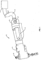
- Figures 1 and 2 illustrate pneumatic tools 10 that each includes an air motor 12, and a gear head 14 with a spindle 15.
- a connector 20 is positioned between the air motor 12 and an air supply 17. The air travels from the supply 17 to the connector 20 through a hose 18.
- Air may be supplied from a variety of different supplies 17 including but not limited to an air compressor and a pressurized tank. Although most tools 10 are powered using air, other types of gases may also be used, such as but not limited to oxygen-free nitrogen and carbon dioxide.
- the gear head 14 includes gears that are arranged to provide rotation and/or axial movement to the spindle 15.
- the spindle 15 may be equipped to receive a tool bit at a forward end to operate on a workpiece.
- Figures 1 and 2 include feed drills used for drilling holes in workpieces formed of substances such as steel, aluminum, titanium, and composites.
- Various tools 10 may include various shapes and sizes, and different tools 10 may perform a variety of different functions.
- Figure 1 illustrates a right-angle tool in which the air motor 12 is aligned perpendicular to an axis of the spindle 15.
- Figure 2 illustrates an inline configuration with the air motor 12 generally parallel with the axis of the spindle 15.
- Figures 1 and 2 include feed drills, although various other air-powered tools 10 are applicable to the low pressure shut off disclosed in this application.
- the various tools 10 may include various shapes and sizes, and different tools 10 may perform a variety of different functions.
- the air motor 12 may include an air logic system that controls one or more functions of the tool 10.
- the air logic system operates using the input air from the air supply 17.
- the various functions performed by the air logic system include but are not limited to opening and closing a variety of valves and/or moving pistons from first to second positions.
- the efficient operation of the tool 10 is reliant on a certain minimum air supply pressure. This pressure is needed to operate the functional aspects of the tool and also to provide for air for operation of the air logic system.
- the air supply pressure is required to power the gear head 14 to drive the spindle 15 to drill a hole in the workpiece. Given that, as the air pressure lowers, the performance of the tool 10 will deteriorate. It is desirable to provide a manner of preventing operation of the tool 10 if the air pressure drops too low.
- the tool 10 is equipped with a valve 30 that provides air to operate the air motor 12 and control logic system when the minimum air pressure is available. In the event that the air pressure is too low, the valve 30 stops the operation of the tool 10.
- FIGS 3A and 3B schematically illustrate a valve 30 located in a body 40 along an air supply line between the air supply 17 and the operational components of the air motor 12 and the air logic system.
- the valve 30 may be located at various locations along the air supply line, including but not limited to the connector 20, and an upstream portion of the air motor 12.
- the valve 30 is located in the body 40 of the connector 20.
- the air supply line includes an air inlet 41 that receives air supplied by the air supply 17, and an air outlet 42 that leads to the air motor 12 and air logic system.
- a secondary air inlet 43 is also positioned at a lower section of the valve 30. The secondary air inlet 43 forms part of the air logic system and is to move the piston 36 from a first valve closed position to a second valve open position.
- the valve 30 includes a movable shaft 34 that moves between a first closed orientation as illustrated in Figure 3A and a second open orientation as illustrated in Figure 3B .
- a first piston 33 extends radially outwardly from a first axial position along the shaft 34.
- a second piston 36 extends radially outwardly from a second axial position along the shaft 34.
- a manual shut-off button 37 is also mounted to the shaft 34. In one or more embodiments, the button 37 is positioned at an end of the shaft 34.
- a biasing member 35 applies a force to maintain the shaft 34 in the first closed orientation. In one specific embodiment, the biasing member 35 extends around the shaft 34 between the second piston 36 and a stop 47.
- the shaft 34 is positioned with the first piston 33 positioned in a narrow neck 44 formed in the body 40.
- the neck 44 is positioned between the air inlet 41 and outlet 42.
- the piston 33 is sized to extend across the neck 44 to prevent air from flowing from the inlet 41 to the outlet 42.
- a gasket or seal 31 may be positioned on the peripheral edge of the piston 33 to provide contact with the walls of the neck 44 to further prevent air flow.
- the air may be totally prevented from moving from the inlet 41 to the outlet 42 when the shaft 34 is in the closed orientation.
- a limited amount of air moves past through the neck 44 when in the first closed orientation. This small amount of air is not enough to operate the tool 10 or air logic system.
- the biasing member 35 biases the shaft 34 to this first closed orientation.
- a bottom edge of the shaft 34 or piston 36 contacts against a bottom wall 32 of a bore 49 to control an extent of movement of the shaft 34 in the first closed orientation.
- Movement from the first closed orientation to the second open orientation occurs by opening the second inlet 43. This may occur due to the operator pressing a switch, or some aspect of the air logic system opening a valve along a secondary supply line that feeds to the second inlet 43.
- a bottom surface of the piston 36 includes a surface area A2 and is sized to extend across and fill the bore 49.
- a gasket or seal 31 may also extend around the periphery to contact against the sidewalls of the bore 49.
- Air entering the bore 49 through the secondary inlet 43 acts on the bottom of the piston 36 and applies a force that is greater than the force of the biasing member 35. Therefore, the shaft 34 slides within the bore 39 towards the second open orientation.
- the first piston 33 that is connected to the shaft 34 moves out of the neck 44 and no longer blocks the air from flowing from the inlet 41 to the outlet 42. This provides for the air to flow to the air motor 12 and air logic system.
- the air from the secondary inlet 43 is supplied to the bore 49 for just a brief period of time (i.e., a pulse). This air applies a force that starts the shaft 34 moving towards the second open orientation. This pulse is adequate to move the shaft 34 fully to the second open orientation.
- the shaft 34 moves a distance in the second open orientation to position the piston 33 in a bore 48. Once in the second open orientation, the shaft 34 remains at this position due to the force of the air that moves along the air path acting on the bottom of the piston 33 which maintains the piston 33 in the bore 48.
- the bottom of the piston 33 includes an area A1 against which the air applies a force.
- the force applied to the piston 33 is greater than that being applied by the biasing member 35.
- the area A1 and biasing member 35 are sized such the air pressure force overcomes the biasing member compression force based on the required minimum air pressure for tool operation. If the pressure drops below that pre-determined value, the biasing member 35 overcomes the low air pressure causing the shaft 34 to move to the first closed orientation thereby shutting off the air supplied to the tool 10 and preventing operation at low pressure.
- the operator While the shaft 34 is in the second open orientation and the tool 10 is running, the operator is able to press the manual shut-off button 37 to close the valve 30.
- the force required to press the shut-off button 37 is low as the force of the air acting on A1 is slightly above the force of the biasing member 35. Further, the amount of movement of the shaft 34 through pressing the shut-off button 37 is short as the movement just needs to unseat the piston 33 from the bore 48. Once the seal between the peripheral edge of the piston 33 and the side wall of the bore 48 is broken, the biasing member 35 will act to move the shaft 34 to the first closed orientation to shut the tool 10 off.
- Figures 4A and 4B illustrate embodiments of the valve 30 in the closed and second open orientations.
- the piston 33 prevents the air from the inlet 41 from getting to the air motor 12.
- the movement to the second open orientation starts upon receipt of a start signal with the piston 36 acting as the actuator for the start signal.
- a start button (not illustrated) or otherwise causes the valve 30 to move, air is supplied to the bottom of the piston 36 through the secondary inlet 43.
- the shaft 34 is positioned to supply air to the air motor 12.
- the movement from the closed to second open orientations is at least partially caused by the air from the secondary inlet 43 acting on area A2 of the bottom of the piston 36.
- This force is sized to overcome the force of the biasing member 35 and provide for movement of the shaft 34.
- the shut-off button 37 also extends beyond the valve body 40 giving easy and obvious access for emergency shut off to an operator (see also Figures 1 and 2 ).
- the signal to shift the start piston 36 is part of the standard tool air logic.
- the air motor 12 starts the air supplied through the secondary inlet 43 is stopped.
- the air from the inlet 41 acting on the underside of piston 33 (based on area A1) acts against biasing member 35 and maintains the valve 30 in the second open orientation.
- the area A1 and biasing member 35 are sized such the air pressure force overcomes the biasing member compression force based on the required minimum air pressure for tool operation.
- shut-off button 37 can be pressed to close the valve 30.
- the force required on the shut-off button 37 can be kept low and the stop will have a minimum travel just to unseat the piston 33 in the housing bore 48. As illustrated in Figure 5 , once the seal is broken, the biasing member 35 will act to shut the tool off and return the valve 30 to the first closed orientation.
- the biasing member 35 may include a variety of different configurations.
- the biasing member 35 may include a single member, or multiple members.
- the multiple members may be the same or may be different.
- the members may include, but are not limited to Belleville washers, wave washers, wave springs and compression springs.
Landscapes
- Engineering & Computer Science (AREA)
- Mechanical Engineering (AREA)
- General Engineering & Computer Science (AREA)
- Physics & Mathematics (AREA)
- Fluid Mechanics (AREA)
- Automatic Tool Replacement In Machine Tools (AREA)
- Retarders (AREA)
- Transmission Devices (AREA)
- Portable Nailing Machines And Staplers (AREA)
- Portable Power Tools In General (AREA)
- Gear Transmission (AREA)
- Details Of Spanners, Wrenches, And Screw Drivers And Accessories (AREA)
Description
- The present application claims priority to
U.S. Application No. 61/769,736 filed on February 26, 2013 61/822,959 filed on May 14, 2013 - The present application is directed to a pneumatic tool and, more specifically, to a pneumatic tool with a low pressure shut off to stop operation of the tool when input air pressure falls below a predetermined level.
- Pneumatic tools are power tools driven by compressed air supplied by a compressor or storage tank such as an air cylinder. Pneumatic tools are popular because they are generally safer to use than electric powered tools. Pneumatic tools may also have a higher power-to-weight ratio making them smaller and lighter thereby facilitating their use. Types of pneumatic tools include but are not limited to air wrench, air ratchet, jackhammer, pneumatic drill, and pneumatic nail gun.
- Pneumatic tools are designed to operate provided there is an adequate input air pressure. The operation of the tool can be significantly affected if the input air pressure is allowed to drop too low. Low air pressure may results in reduced tool speed, reduced tool power, and possible stalling issues.
- Document
US 1 312 644 discloses a low pressure shut off according to the preamble of independent claim 1. - Existing designs have provided for a low pressure shut off. These designs have included a tip valve actuated by a piston with a spring force that can stop the air flow in the event the pressure becomes too low. However, there have been issues with the amount of air that a tip valve can flow. Increasing the amount of air flow increases the power that the air tool can provide which can allow the tool to do more or to do the same thing faster.
- The present application is directed to low pressure shut off for a pneumatic tool. The shut off provides for the tool to operate when the air pressure of incoming air exceeds a predetermined amount. The shut off prevents operation of the tool when the air pressure falls below the predetermined amount.
- One embodiment is a low pressure shut off for a pneumatic tool according to claim 1
- The air path may include a neck positioned between the main inlet and the outlet, and the neck and the first piston may include a common sectional shape and size such that the first piston blocks the air path at the neck in the first position.
- A flexible gasket may be mounted at a periphery of the first piston such that the gasket contacts against the neck in the first position.
- The low pressure shut off may include a second bore with sidewalls and a bottom with the second piston positioned in the second bore in the first position and having a common sectional shape and size as the second bore.
- The second bore may be positioned away from an air path that extends between the main inlet and the outlet.
- The low pressure shut off may include a first bore positioned away from an air path that extends between the main inlet and the outlet. The first bore may include a sectional shape and size that matches the first piston. The first piston may be positioned in the first bore in the second position and away from the first bore in the first position.
- The biasing member may be positioned away from an air path that extends between the main inlet and the outlet.
- The low pressure shut off may include a shut-off button at an end of the shaft. The shut-off button may extend outward from a housing that extends around the low pressure shut off a greater amount in the second position than in the first position.
- Another embodiment is directed to a method according to claim 9.
- The method may also include biasing the first piston towards the first position.
- The biasing force that biases the first piston towards the first position may be less than the second force that maintains the first piston in the second position when the air pressure is above the preset level.
- The method may include moving each of the first and second pistons an equal amount between the second and first positions as the first and second pistons are each connected to a shaft.
- The method may include sealing the first piston in a bore in the second position and preventing air from the air path from acting on an opposing side of the first piston that faces away from the air path.
- The method may include moving air through a secondary inlet and applying air against the second piston to create the first force. The secondary inlet may be positioned away from the air path that extends from the air inlet to the air outlet.
- The method may include moving a manual shut-off button outward relative to an outer housing when moving the first piston from the first position to the second position.
- The various aspects of the various embodiments may be used alone or in any combination, as is desired.
-
-
Figure 1 is a perspective view of a first type of a feed tool. -
Figure 2 is a perspective view of a second type of a feed tool. -
Figure 3A is a side schematic view of a low pressure valve in a first closed orientation. -
Figure 3B is a side schematic view of a low pressure valve in a second open orientation. -
Figure 4A is a side sectional view of a low pressure valve in a first closed orientation. -
Figure 4B is a side sectional view of a low pressure valve in a second open orientation. -
Figure 5 is a side sectional view of a piston moving out of a housing bore in a low pressure valve. - The present application is directed to a low pressure shut off for a pneumatic tool. The tool may include an air path for input air. A shaft is positioned along the air path and movable relative to the air path between a first position and a second position. First and second pistons are spaced axially apart along the shaft and each extends radially outward beyond the shaft. In the first position, the first piston extends across the air path to block the air path. In the first position, the second piston is positioned to be acted on by air from a secondary inlet to apply a force to the second piston that overcomes a biasing force and moves it to the second position that positions the first piston to allow air to flow along the air path.
-
Figures 1 and2 illustratepneumatic tools 10 that each includes anair motor 12, and agear head 14 with aspindle 15. Aconnector 20 is positioned between theair motor 12 and anair supply 17. The air travels from thesupply 17 to theconnector 20 through ahose 18. Air may be supplied from a variety ofdifferent supplies 17 including but not limited to an air compressor and a pressurized tank. Althoughmost tools 10 are powered using air, other types of gases may also be used, such as but not limited to oxygen-free nitrogen and carbon dioxide. - The
gear head 14 includes gears that are arranged to provide rotation and/or axial movement to thespindle 15. Thespindle 15 may be equipped to receive a tool bit at a forward end to operate on a workpiece.Figures 1 and2 include feed drills used for drilling holes in workpieces formed of substances such as steel, aluminum, titanium, and composites.Various tools 10 may include various shapes and sizes, anddifferent tools 10 may perform a variety of different functions.Figure 1 illustrates a right-angle tool in which theair motor 12 is aligned perpendicular to an axis of thespindle 15.Figure 2 illustrates an inline configuration with theair motor 12 generally parallel with the axis of thespindle 15.Figures 1 and2 include feed drills, although various other air-poweredtools 10 are applicable to the low pressure shut off disclosed in this application. Thevarious tools 10 may include various shapes and sizes, anddifferent tools 10 may perform a variety of different functions. - The
air motor 12 may include an air logic system that controls one or more functions of thetool 10. The air logic system operates using the input air from theair supply 17. The various functions performed by the air logic system include but are not limited to opening and closing a variety of valves and/or moving pistons from first to second positions. - The efficient operation of the
tool 10 is reliant on a certain minimum air supply pressure. This pressure is needed to operate the functional aspects of the tool and also to provide for air for operation of the air logic system. In the embodiment of a positive feed drill, the air supply pressure is required to power thegear head 14 to drive thespindle 15 to drill a hole in the workpiece. Given that, as the air pressure lowers, the performance of thetool 10 will deteriorate. It is desirable to provide a manner of preventing operation of thetool 10 if the air pressure drops too low. - To address the low pressure issue, the
tool 10 is equipped with avalve 30 that provides air to operate theair motor 12 and control logic system when the minimum air pressure is available. In the event that the air pressure is too low, thevalve 30 stops the operation of thetool 10. -
Figures 3A and 3B schematically illustrate avalve 30 located in abody 40 along an air supply line between theair supply 17 and the operational components of theair motor 12 and the air logic system. Thevalve 30 may be located at various locations along the air supply line, including but not limited to theconnector 20, and an upstream portion of theair motor 12. In one specific embodiment, thevalve 30 is located in thebody 40 of theconnector 20. The air supply line includes anair inlet 41 that receives air supplied by theair supply 17, and anair outlet 42 that leads to theair motor 12 and air logic system. Asecondary air inlet 43 is also positioned at a lower section of thevalve 30. Thesecondary air inlet 43 forms part of the air logic system and is to move thepiston 36 from a first valve closed position to a second valve open position. - The
valve 30 includes amovable shaft 34 that moves between a first closed orientation as illustrated inFigure 3A and a second open orientation as illustrated inFigure 3B . Afirst piston 33 extends radially outwardly from a first axial position along theshaft 34. Asecond piston 36 extends radially outwardly from a second axial position along theshaft 34. A manual shut-off button 37 is also mounted to theshaft 34. In one or more embodiments, thebutton 37 is positioned at an end of theshaft 34. A biasingmember 35 applies a force to maintain theshaft 34 in the first closed orientation. In one specific embodiment, the biasingmember 35 extends around theshaft 34 between thesecond piston 36 and a stop 47. - In the first closed orientation as illustrated in
Figure 3A , theshaft 34 is positioned with thefirst piston 33 positioned in anarrow neck 44 formed in thebody 40. Theneck 44 is positioned between theair inlet 41 andoutlet 42. Thepiston 33 is sized to extend across theneck 44 to prevent air from flowing from theinlet 41 to theoutlet 42. A gasket or seal 31 may be positioned on the peripheral edge of thepiston 33 to provide contact with the walls of theneck 44 to further prevent air flow. The air may be totally prevented from moving from theinlet 41 to theoutlet 42 when theshaft 34 is in the closed orientation. In one or more embodiments, a limited amount of air moves past through theneck 44 when in the first closed orientation. This small amount of air is not enough to operate thetool 10 or air logic system. The biasingmember 35 biases theshaft 34 to this first closed orientation. In one or more embodiments, a bottom edge of theshaft 34 orpiston 36 contacts against abottom wall 32 of abore 49 to control an extent of movement of theshaft 34 in the first closed orientation. - Movement from the first closed orientation to the second open orientation occurs by opening the
second inlet 43. This may occur due to the operator pressing a switch, or some aspect of the air logic system opening a valve along a secondary supply line that feeds to thesecond inlet 43. A bottom surface of thepiston 36 includes a surface area A2 and is sized to extend across and fill thebore 49. A gasket or seal 31 may also extend around the periphery to contact against the sidewalls of thebore 49. Air entering thebore 49 through thesecondary inlet 43 acts on the bottom of thepiston 36 and applies a force that is greater than the force of the biasingmember 35. Therefore, theshaft 34 slides within the bore 39 towards the second open orientation. Thefirst piston 33 that is connected to theshaft 34 moves out of theneck 44 and no longer blocks the air from flowing from theinlet 41 to theoutlet 42. This provides for the air to flow to theair motor 12 and air logic system. - In one or more embodiments, the air from the
secondary inlet 43 is supplied to thebore 49 for just a brief period of time (i.e., a pulse). This air applies a force that starts theshaft 34 moving towards the second open orientation. This pulse is adequate to move theshaft 34 fully to the second open orientation. - The
shaft 34 moves a distance in the second open orientation to position thepiston 33 in abore 48. Once in the second open orientation, theshaft 34 remains at this position due to the force of the air that moves along the air path acting on the bottom of thepiston 33 which maintains thepiston 33 in thebore 48. The bottom of thepiston 33 includes an area A1 against which the air applies a force. The force applied to thepiston 33 is greater than that being applied by the biasingmember 35. The area A1 and biasingmember 35 are sized such the air pressure force overcomes the biasing member compression force based on the required minimum air pressure for tool operation. If the pressure drops below that pre-determined value, the biasingmember 35 overcomes the low air pressure causing theshaft 34 to move to the first closed orientation thereby shutting off the air supplied to thetool 10 and preventing operation at low pressure. - While the
shaft 34 is in the second open orientation and thetool 10 is running, the operator is able to press the manual shut-off button 37 to close thevalve 30. The force required to press the shut-off button 37 is low as the force of the air acting on A1 is slightly above the force of the biasingmember 35. Further, the amount of movement of theshaft 34 through pressing the shut-off button 37 is short as the movement just needs to unseat thepiston 33 from thebore 48. Once the seal between the peripheral edge of thepiston 33 and the side wall of thebore 48 is broken, the biasingmember 35 will act to move theshaft 34 to the first closed orientation to shut thetool 10 off. -
Figures 4A and4B illustrate embodiments of thevalve 30 in the closed and second open orientations. As illustrated inFigure 4A , in the first closed orientation thepiston 33 prevents the air from theinlet 41 from getting to theair motor 12. The movement to the second open orientation starts upon receipt of a start signal with thepiston 36 acting as the actuator for the start signal. When the operator pushes a start button (not illustrated) or otherwise causes thevalve 30 to move, air is supplied to the bottom of thepiston 36 through thesecondary inlet 43. - In the second open orientation as illustrated in
Figure 4B , theshaft 34 is positioned to supply air to theair motor 12. The movement from the closed to second open orientations is at least partially caused by the air from thesecondary inlet 43 acting on area A2 of the bottom of thepiston 36. This force is sized to overcome the force of the biasingmember 35 and provide for movement of theshaft 34. In the second open orientation, the shut-off button 37 also extends beyond thevalve body 40 giving easy and obvious access for emergency shut off to an operator (see alsoFigures 1 and2 ). - The signal to shift the
start piston 36 is part of the standard tool air logic. In one or more embodiments, once theair motor 12 starts the air supplied through thesecondary inlet 43 is stopped. The air from theinlet 41 acting on the underside of piston 33 (based on area A1) acts against biasingmember 35 and maintains thevalve 30 in the second open orientation. The area A1 and biasingmember 35 are sized such the air pressure force overcomes the biasing member compression force based on the required minimum air pressure for tool operation. Based on Force = Pressure x Area, if the pressure drops below that pre-determined value, the biasingmember 35 can overcome the low air pressure and will cause the valve to close and the system to return to the initial state shown inFigure 4A thereby shutting off thetool 12 and preventing operation at low pressure. - While the tool is running, even if the air pressure is sufficient to maintain the
valve 30 in the open position, the shut-off button 37 can be pressed to close thevalve 30. A further enhancement of this design is that the force required on the shut-off button 37 can be kept low and the stop will have a minimum travel just to unseat thepiston 33 in the housing bore 48. As illustrated inFigure 5 , once the seal is broken, the biasingmember 35 will act to shut the tool off and return thevalve 30 to the first closed orientation. - The biasing
member 35 may include a variety of different configurations. The biasingmember 35 may include a single member, or multiple members. The multiple members may be the same or may be different. The members may include, but are not limited to Belleville washers, wave washers, wave springs and compression springs.
Claims (15)
- A low pressure shut off for a pneumatic tool comprising:an air path comprising a main inlet (41), an outlet (42), and a secondary inlet (43);a shaft (34) positioned along the air path between the main inlet (41) and the outlet (42), the shaft (34) being movable relative to the air path between a first position and a second position;a biasing member (35) acting on the shaft (34) to bias the shaft towards the first position;characterized by:first and second pistons (33, 36) spaced axially apart along the shaft (34) and each extending radially outward beyond the shaft (34);in the first position, the first piston (33) extends across the air path between the main inlet (41) and the outlet (42) to block the air path;in the first position, the second piston (36) is positioned to be acted on by air from the secondary inlet (43) to apply a force to the second piston (36) that overcomes the force of the biasing member (35) and position the shaft (34) at the second position with the first piston (33) away from the air path to allow air to flow along the air path between the main inlet (41) and the outlet (42).
- The low pressure shut off according to claim 1, wherein the air path includes a neck (44) positioned between the main inlet (41) and the outlet (42), the neck (44) and the first piston (33) including a common sectional shape and size such that the first piston (33) blocks the air path at the neck (44) in the first position.
- The low pressure shut off according to claim 2, further comprising a flexible gasket mounted at a periphery of the first piston (33) such that the gasket contacts against the neck (44) in the first position.
- The low pressure shut off according to claim 1, further comprising a second bore (49) with sidewalls and a bottom (32), the second piston (36) positioned in the second bore (49) in the first position and having a common sectional shape and size as the second bore (49).
- The low pressure shut off according to claim 4, wherein the second bore (49) is positioned away from the air path that extends between the main inlet (41) and the outlet (42).
- The low pressure shut off according to claim 1, further comprising a first bore (48) positioned away from the air path that extends between the main inlet (41) and the outlet (42), the first bore (48) including a sectional shape and size that matches the first piston (33), the first piston (33) being positioned in the first bore (48) in the second position and away from the first bore (48) in the first position.
- The low pressure shut off according to claim 1, wherein the biasing member (35) is positioned away from the air path that extends between the main inlet (41) and the outlet (42).
- The low pressure shut off according to claim 1, further comprising a shut-off button (37) at an end of the shaft (34), the shut-off button (37) extending outward from a housing that extends around the low pressure shut off a greater amount in the second position than in the first position.
- A method of operating a valve for a pneumatic tool, the method comprising:providing a valve that includes first and second pistons (33, 36) that is movable relative to an air path that extends between an air inlet (41) and an air outlet (42);characterized by:positioning the first piston (33) in a first position at a neck (44) in the air path and blocking air from flowing along the air path from an air inlet (41) to an air outlet (42);applying a first force to a second piston (36) and moving the first piston (33) to a second position out of the neck (44) and allowing the air to flow along the air path from the air inlet (41) to the air outlet (42);applying a second force to the first piston (33) through the air flowing along the air path and maintaining the first piston (33) in the second position after the first force is removed from the second piston (36); andwhen air pressure of the air flowing along the air path falls below a preset level, moving the first piston (33) to the first position and blocking air from flowing along the air path from the air inlet (41) to the air outlet (42).
- The method of claim 9, further comprising biasing the first piston (33) towards the first position.
- The method of claim 10, wherein a biasing force that biases the first piston (33) towards the first position is less than the second force that maintains the first piston (33) in the second position when the air pressure is above the preset level.
- The method according to claim 9, further comprising moving each of the first and second pistons (33, 36) an equal amount between the first and second positions as the first and second pistons (33, 36) are each connected to a shaft (34).
- The method according to claim 9, further comprising sealing the first piston (33) in a bore (48) in the second position and preventing air from the air path from acting on an opposing side of the first piston (33) that faces away from the air path.
- The method according to claim 9, further comprising moving air through a secondary Inlet (43) and applying air against the second piston (36) to create the first force, the secondary inlet (43) being positioned away from the air path that extends from the air inlet (41) to the air outlet (42).
- The method according to claim 9, further comprising moving a manual shut-off button (37) outward relative to an outer housing when moving the first piston (33) from the first position to the second position.
Applications Claiming Priority (3)
| Application Number | Priority Date | Filing Date | Title |
|---|---|---|---|
| US201361769736P | 2013-02-26 | 2013-02-26 | |
| US201361822959P | 2013-05-14 | 2013-05-14 | |
| PCT/US2014/018104 WO2014133978A1 (en) | 2013-02-26 | 2014-02-24 | Low pressure shut off for a pneumatic tool |
Publications (2)
| Publication Number | Publication Date |
|---|---|
| EP2961572A1 EP2961572A1 (en) | 2016-01-06 |
| EP2961572B1 true EP2961572B1 (en) | 2016-09-21 |
Family
ID=50277349
Family Applications (5)
| Application Number | Title | Priority Date | Filing Date |
|---|---|---|---|
| EP14710135.6A Not-in-force EP2961564B1 (en) | 2013-02-26 | 2014-02-24 | Positive feed tool with a slip clutch and a method to prevent jamming |
| EP14710137.2A Not-in-force EP2961574B1 (en) | 2013-02-26 | 2014-02-24 | Positive feed tool with a modular architecture |
| EP14710141.4A Not-in-force EP2961565B1 (en) | 2013-02-26 | 2014-02-24 | Positive feed tool with interchangeable gears to adjust a feed rate and method therefor |
| EP14710142.2A Not-in-force EP2961572B1 (en) | 2013-02-26 | 2014-02-24 | Low pressure shut off for a pneumatic tool |
| EP14710134.9A Not-in-force EP2961563B1 (en) | 2013-02-26 | 2014-02-24 | Positive feed tool and method therefor |
Family Applications Before (3)
| Application Number | Title | Priority Date | Filing Date |
|---|---|---|---|
| EP14710135.6A Not-in-force EP2961564B1 (en) | 2013-02-26 | 2014-02-24 | Positive feed tool with a slip clutch and a method to prevent jamming |
| EP14710137.2A Not-in-force EP2961574B1 (en) | 2013-02-26 | 2014-02-24 | Positive feed tool with a modular architecture |
| EP14710141.4A Not-in-force EP2961565B1 (en) | 2013-02-26 | 2014-02-24 | Positive feed tool with interchangeable gears to adjust a feed rate and method therefor |
Family Applications After (1)
| Application Number | Title | Priority Date | Filing Date |
|---|---|---|---|
| EP14710134.9A Not-in-force EP2961563B1 (en) | 2013-02-26 | 2014-02-24 | Positive feed tool and method therefor |
Country Status (4)
| Country | Link |
|---|---|
| US (6) | US9808896B2 (en) |
| EP (5) | EP2961564B1 (en) |
| CN (5) | CN105228798B (en) |
| WO (5) | WO2014133978A1 (en) |
Families Citing this family (28)
| Publication number | Priority date | Publication date | Assignee | Title |
|---|---|---|---|---|
| DE102011005553A1 (en) * | 2010-10-15 | 2012-04-19 | Robert Bosch Gmbh | Hand-held power tool with a Spindellockvorrichtung |
| US9038745B2 (en) * | 2010-12-20 | 2015-05-26 | Brigham Young University | Hand power tool and drive train |
| SE1151040A1 (en) * | 2011-11-04 | 2013-04-09 | Atlas Copco Ind Tech Ab | Motor-driven tool and method for operating an automated drilling operation |
| FR3000693B1 (en) * | 2013-01-09 | 2015-06-19 | Seti Tec | BIMOTER DRILL WITH CONTROLLED ADVANCE SPEED |
| CN105228798B (en) * | 2013-02-26 | 2017-06-09 | 艾沛克斯品牌公司 | Active feed tool with modular structure |
| FR3018712B1 (en) | 2014-03-20 | 2016-12-30 | Arts | DRILLING TOOL WITH TWO COAXIAL ENGINES |
| US20150347357A1 (en) * | 2014-05-30 | 2015-12-03 | Rovi Guides, Inc. | Systems and methods for automatic text recognition and linking |
| WO2016028287A1 (en) | 2014-08-20 | 2016-02-25 | Apex Brands, Inc. | Positive feed tool with improved shift from forward to retract |
| US9729506B2 (en) | 2014-08-22 | 2017-08-08 | Shape Security, Inc. | Application programming interface wall |
| KR101570692B1 (en) * | 2015-01-07 | 2015-11-20 | 주식회사 에이와이중공업 | Hydraulic breaker |
| US10603723B1 (en) * | 2015-08-27 | 2020-03-31 | M4 Sciences, Llc | Machining system spindle for modulation-assisted machining |
| US10583538B2 (en) | 2015-11-16 | 2020-03-10 | Apex Brands, Inc. | Feed oscillation via variable pitch gears |
| US10232446B2 (en) * | 2015-11-16 | 2019-03-19 | Apex Brands, Inc. | Adaptive drilling with piezo-electric feed oscillator |
| US10124454B2 (en) | 2015-11-16 | 2018-11-13 | Apex Brands, Inc. | Oscillating thrust bearing |
| US10569403B2 (en) * | 2016-06-21 | 2020-02-25 | Tti (Macao Commercial Offshore) Limited | Gas spring fastener driver |
| CN106763830A (en) * | 2016-12-14 | 2017-05-31 | 安徽海拓志永智能装备股份有限公司 | A kind of low noise rapid-release valve |
| CN106641278A (en) * | 2016-12-14 | 2017-05-10 | 安徽海拓志永智能装备股份有限公司 | Efficient rapid release valve |
| CN106763808A (en) * | 2016-12-15 | 2017-05-31 | 安徽海拓志永智能装备股份有限公司 | Efficient two-position |
| CN106763807A (en) * | 2016-12-15 | 2017-05-31 | 安徽海拓志永智能装备股份有限公司 | A kind of large-scale two-position |
| CN106965019A (en) * | 2017-04-13 | 2017-07-21 | 上海司恩金属加工技术有限公司 | The special machine tool that a kind of crystallizer copper pipe embedded SMA actuators are used |
| TWI607842B (en) * | 2017-05-04 | 2017-12-11 | Gison Machinery Co Ltd | Low pressure warning device, low pressure warning device and low pressure warning method for pneumatic tools |
| TWI610771B (en) * | 2017-06-29 | 2018-01-11 | 力肯實業股份有限公司 | Pneumatic switching structure of pneumatic rotary hand tool |
| US11534903B2 (en) * | 2017-08-28 | 2022-12-27 | Apex Brands, Inc. | Power tool two-stage trigger |
| CN112166005A (en) * | 2018-07-18 | 2021-01-01 | 艾沛克斯品牌公司 | Portable power drill with pump |
| CN110293503B (en) * | 2019-07-03 | 2021-04-02 | 刘安胜 | Bolt Twisting Device with Adjusting Structure |
| JP7691729B2 (en) * | 2021-05-31 | 2025-06-12 | 大肯精密株式会社 | Drilling machine and drilling method |
| CN113146282B (en) * | 2021-05-31 | 2025-05-02 | 东莞市鼎胜新材料科技有限公司 | Self-pressure-supplying angle head |
| CN114633140A (en) * | 2022-04-20 | 2022-06-17 | 科德数控股份有限公司 | High-speed nut rotary feed screw device |
Family Cites Families (77)
| Publication number | Priority date | Publication date | Assignee | Title |
|---|---|---|---|---|
| US1312644A (en) | 1919-08-12 | Valve | ||
| US843391A (en) * | 1906-04-05 | 1907-02-05 | Edward J Ferris | Cylinder-cock for locomotives. |
| US2393272A (en) * | 1943-11-09 | 1946-01-22 | Harry R Van Deventer | Combining telephones and phonographs |
| US2728547A (en) * | 1950-11-24 | 1955-12-27 | Exxon Research Engineering Co | Mud release valve |
| US2893272A (en) * | 1957-03-18 | 1959-07-07 | Buckeye Tools Corp | Automatic tool |
| US3411385A (en) * | 1966-08-08 | 1968-11-19 | Quackenbush Arthur B | Positive feeding structure |
| US3590582A (en) * | 1968-10-09 | 1971-07-06 | Aro Corp | Work control system |
| US3577807A (en) | 1968-10-31 | 1971-05-04 | Rockwell Mfg Co | Portable power tool |
| US3802792A (en) | 1972-12-04 | 1974-04-09 | A Quackenbush | Positive feeding structure with programmed spindle speed control |
| US4308892A (en) | 1979-10-09 | 1982-01-05 | The Bendix Corporation | Rotary valve |
| JPS5775712A (en) * | 1980-10-30 | 1982-05-12 | Brother Ind Ltd | Borer equipped with step feed function |
| DE3267739D1 (en) | 1981-03-05 | 1986-01-16 | Titanox Sa | Adjustable positive feed drill |
| US4642098A (en) | 1981-06-29 | 1987-02-10 | Valleylab, Inc. | IV system and controller and combination IV filter and pump assembly for use therein and method |
| US4443139A (en) | 1982-03-18 | 1984-04-17 | In-Tex Tool Corporation | Positive feed drill |
| US4592681A (en) | 1983-10-31 | 1986-06-03 | Dresser Industries, Inc. | Retraction apparatus for automatic feed drills or the like |
| US4538942A (en) * | 1984-06-13 | 1985-09-03 | P.V. Tool, Inc | Positive feed drill with stop control |
| US4612831A (en) * | 1985-02-19 | 1986-09-23 | Lehmkuhl Robert A | Automatic boring tool |
| US4702650A (en) * | 1985-08-08 | 1987-10-27 | Dresser Industries, Inc. | Positive feed drill use counter |
| EP0273055B1 (en) * | 1986-04-05 | 1992-01-29 | Nagase Iron Works Co., Ltd. | Machine and method of grinding molding die |
| GB8620690D0 (en) | 1986-08-27 | 1986-10-08 | Desoutter Ltd | Positive feed device |
| US4782726A (en) | 1987-01-13 | 1988-11-08 | Ryder Internation Corporation | Lead screw driver |
| JP2764164B2 (en) | 1988-03-25 | 1998-06-11 | パイロットインキ株式会社 | Spray equipment |
| US5205681A (en) | 1989-06-30 | 1993-04-27 | Dresser Industries, Inc. | Mechanical peck drill and method |
| GB8916702D0 (en) | 1989-07-21 | 1989-09-06 | Avdel Systems Ltd | Repetition riveting apparatus |
| US5027978A (en) | 1989-08-24 | 1991-07-02 | Minnesota Mining And Manufacturing Company | Method and apparatus for precision pumping, ratioing, and dispensing of work fluid(s) |
| US5149230A (en) * | 1991-03-04 | 1992-09-22 | Nett Daniel R | Rotating dual attachment receptacle apparatus tool |
| CN2123665U (en) * | 1992-03-24 | 1992-12-02 | 吕建军 | Low pressuse valve |
| CN1154902A (en) | 1996-01-15 | 1997-07-23 | 京特热渠道有限公司 | Hot runner system |
| US5860446A (en) | 1996-03-12 | 1999-01-19 | Climax Portable Machine Tools, Inc. | Method and apparatus for safely controlling fluid flow |
| US6162030A (en) * | 1997-06-13 | 2000-12-19 | Encynova International, Inc. | Zero leakage valveless positive fluid displacement device |
| FR2766846B1 (en) | 1997-08-04 | 1999-10-22 | Thibeau | DEVICE FOR FORMING A SHEET OF FIBER HAMMER, PARTICULARLY FOR LOADING A TEXTILE MACHINE SUCH AS A CARD |
| US5974835A (en) | 1997-11-06 | 1999-11-02 | Emhart Glass S.A. | I.S. machine |
| US6284047B1 (en) * | 1998-01-13 | 2001-09-04 | Abb K. K. | Rotary atomizing head type coating device |
| US6082468A (en) * | 1998-04-20 | 2000-07-04 | Snap-On Tools Company | Interchangeable grips for power hand tools |
| US6192781B1 (en) | 1998-12-31 | 2001-02-27 | Cooper Technologies Company | Assembly for reversing a fluid driven motor |
| US6540670B1 (en) * | 1999-03-19 | 2003-04-01 | Olympus Optical Co., Ltd. | Endoscope system |
| US6149356A (en) * | 1999-04-15 | 2000-11-21 | China Pneumatic Corporation | Portable pneumatic tool assembled with module units |
| US6536536B1 (en) | 1999-04-29 | 2003-03-25 | Stephen F. Gass | Power tools |
| US6193447B1 (en) | 1999-06-18 | 2001-02-27 | Cooper Technologies Company | Positive feed tool having a retract valve |
| US6261033B1 (en) * | 1999-06-18 | 2001-07-17 | Cooper Technologies Company | Positive feed tool having rectractable members |
| US6196772B1 (en) * | 1999-06-18 | 2001-03-06 | Cooper Technologies Company | Positive feed tool having a clutch |
| WO2001005559A2 (en) | 1999-07-16 | 2001-01-25 | Gass Stephen F | Improved power tools |
| US6776421B2 (en) | 2000-02-10 | 2004-08-17 | Delphi Technologies, Inc. | Fluid sealing system |
| CN1216246C (en) | 2000-03-20 | 2005-08-24 | 贾科米尼公开有限公司 | Improved modular manifolds and improved manifold modules for heating and sanitary systems |
| JP2001315010A (en) * | 2000-05-08 | 2001-11-13 | Mori Seiki Co Ltd | Machine Tools |
| US6219895B1 (en) | 2000-06-27 | 2001-04-24 | Davenport Industries, Llc | Machine tool with servo drive mechanism |
| CN2632425Y (en) * | 2003-06-27 | 2004-08-11 | 北京康拓科技开发总公司 | Double-piston pneumatic diaphragm valves |
| US7303363B2 (en) | 2003-09-10 | 2007-12-04 | Lockheed Martin Corporation | Pneumatic drill |
| US20050279517A1 (en) | 2004-06-21 | 2005-12-22 | Hoffman William H | Screw driving apparatus with attachable and detachable nose sub-assembly for use with single-feed screws or for use with automatic-feed collated screws |
| FR2873315B1 (en) | 2004-07-23 | 2007-12-14 | Recoules Sa Sa | MECHANICAL ADVANCED MACHINING MACHINE AUTHORIZING AN UNFINISHING OPERATION |
| US7048077B2 (en) * | 2004-09-26 | 2006-05-23 | P.V. Tool, Inc. | Drilling machine with pneumatic control |
| FR2881366B1 (en) | 2005-02-01 | 2007-03-16 | Seti Tec Soc Par Actions Simpl | AUTOMATIC STOP MACHINING MACHINE AT THE END OF THE CYCLE |
| US20070039303A1 (en) | 2005-08-19 | 2007-02-22 | Mitchell James D Jr | Auxiliary hydraulic system |
| GB2429991A (en) | 2005-09-07 | 2007-03-14 | Alan Barrows | Water powered impulsive unit |
| DE602006020757D1 (en) | 2005-11-04 | 2011-04-28 | Bosch Gmbh Robert | TORQUE LIMITING FEEDBACK IN AN IMPACT DRILL |
| JP4261559B2 (en) | 2006-06-20 | 2009-04-30 | シーケーディ株式会社 | Air operated valve |
| GB0617369D0 (en) * | 2006-09-02 | 2006-10-11 | Ford Global Tech Llc | Pressure relief valve |
| FR2907695B1 (en) | 2006-10-27 | 2009-06-26 | Cooper Power Tools Sas Soc Par | METHOD FOR DRILLING A BORING AND CORRESPONDING MACHINE |
| FR2915121B1 (en) | 2007-04-17 | 2009-10-09 | Cooper Power Tools Sas Soc Par | MACHINING MACHINE. |
| JP4912976B2 (en) | 2007-07-31 | 2012-04-11 | 日東工器株式会社 | Pneumatic tool |
| CN101377229B (en) | 2007-08-29 | 2012-12-19 | 苏州宝时得电动工具有限公司 | Variable speed tool and its variable speed control method |
| CN201093036Y (en) | 2007-08-31 | 2008-07-30 | 苏州宝时得电动工具有限公司 | Speed changing tool |
| EP2283956B1 (en) * | 2008-04-11 | 2013-04-03 | Honda Motor Co., Ltd. | Device for boring a non-round hole |
| US8522941B1 (en) * | 2009-02-25 | 2013-09-03 | Ahmed Eldessouky | Split-shaft clutching arrangement of a positive feed drill |
| JP5278758B2 (en) * | 2009-05-15 | 2013-09-04 | 本田技研工業株式会社 | Cam drive device and processing method |
| CN101625043B (en) * | 2009-08-13 | 2011-12-21 | 凯迈(洛阳)气源有限公司 | high-pressure reducing valve |
| CN201519891U (en) | 2009-11-03 | 2010-07-07 | 孙彦良 | Machining feeding device |
| US20120045328A1 (en) | 2010-08-17 | 2012-02-23 | Cleveland State University | Power transmission system |
| US9120160B1 (en) * | 2010-10-20 | 2015-09-01 | Ahmed Eldessouky | Positive feed drill |
| EP2672946A2 (en) | 2011-02-13 | 2013-12-18 | The Regents of The University of California | Fluid delivery system |
| CN102320011B (en) | 2011-08-18 | 2013-07-24 | 江阴东辰机械制造股份有限公司 | Coaxial controllable rotating radial feeder |
| US9283334B2 (en) * | 2011-11-23 | 2016-03-15 | Northgate Technologies Inc. | System for identifying the presence and correctness of a medical device accessory |
| JP5854811B2 (en) * | 2011-12-19 | 2016-02-09 | Dmg森精機株式会社 | Machine Tools |
| CN103170686A (en) | 2012-05-21 | 2013-06-26 | 温岭市国邦电气有限公司 | Automatic tapping machine power head capable of fast feed and fast return |
| CN105228798B (en) * | 2013-02-26 | 2017-06-09 | 艾沛克斯品牌公司 | Active feed tool with modular structure |
| US9441645B2 (en) | 2013-05-29 | 2016-09-13 | Patrick Michael Mullen | Proportional servo hydraulic control valve |
| JP6481155B2 (en) | 2014-11-25 | 2019-03-13 | 株式会社テージーケー | Motorized valve |
-
2014
- 2014-02-24 CN CN201480023568.3A patent/CN105228798B/en not_active Expired - Fee Related
- 2014-02-24 EP EP14710135.6A patent/EP2961564B1/en not_active Not-in-force
- 2014-02-24 US US14/188,201 patent/US9808896B2/en not_active Expired - Fee Related
- 2014-02-24 EP EP14710137.2A patent/EP2961574B1/en not_active Not-in-force
- 2014-02-24 CN CN201480023176.7A patent/CN105246648B/en not_active Expired - Fee Related
- 2014-02-24 EP EP14710141.4A patent/EP2961565B1/en not_active Not-in-force
- 2014-02-24 WO PCT/US2014/018104 patent/WO2014133978A1/en not_active Ceased
- 2014-02-24 US US14/770,036 patent/US9707654B2/en not_active Expired - Fee Related
- 2014-02-24 US US14/770,046 patent/US9827641B2/en not_active Expired - Fee Related
- 2014-02-24 US US14/770,040 patent/US9539683B2/en active Active
- 2014-02-24 WO PCT/US2014/018031 patent/WO2014133965A1/en not_active Ceased
- 2014-02-24 WO PCT/US2014/018076 patent/WO2014133972A1/en not_active Ceased
- 2014-02-24 CN CN201480023581.9A patent/CN105189047B/en not_active Expired - Fee Related
- 2014-02-24 US US14/770,029 patent/US9604334B2/en not_active Expired - Fee Related
- 2014-02-24 WO PCT/US2014/018055 patent/WO2014133971A1/en not_active Ceased
- 2014-02-24 WO PCT/US2014/018089 patent/WO2014133976A1/en not_active Ceased
- 2014-02-24 EP EP14710142.2A patent/EP2961572B1/en not_active Not-in-force
- 2014-02-24 US US14/770,019 patent/US9662756B2/en not_active Expired - Fee Related
- 2014-02-24 CN CN201480023689.8A patent/CN105189037B/en not_active Expired - Fee Related
- 2014-02-24 EP EP14710134.9A patent/EP2961563B1/en not_active Not-in-force
- 2014-02-24 CN CN201480023219.1A patent/CN105228793B/en not_active Expired - Fee Related
Also Published As
Similar Documents
| Publication | Publication Date | Title |
|---|---|---|
| US9827641B2 (en) | Low pressure shut off for a pneumatic tool | |
| JP5098351B2 (en) | Pneumatic tool | |
| JP4083383B2 (en) | Pneumatic-operating hydraulic rivet gun | |
| JP5509771B2 (en) | Air driving machine | |
| US20080047721A1 (en) | Pressure regulating mechanism for pneumatic tool and pneumatic tool comprising the same | |
| JP2015505604A (en) | Manual override for valve | |
| WO2018100939A1 (en) | Drive-in machine | |
| US7124837B2 (en) | Pneumatic motor trigger actuator | |
| JP2010023169A (en) | Pneumatic pressure type screw driving machine | |
| US20050077064A1 (en) | Pneumatically operated power tool having mechanism for changing compressed air pressure | |
| US6061901A (en) | Pneumatic screw punching machine | |
| EP0967052B1 (en) | Automatic stop device for screw striking machine | |
| US7194938B2 (en) | Angular impact wrench | |
| US20130134340A1 (en) | Pneumatic control device operated by one hand | |
| US6192781B1 (en) | Assembly for reversing a fluid driven motor | |
| US5159987A (en) | Valve construction for automatic shut-off screwdrivers and the like | |
| JP5694973B2 (en) | Hydraulic pulse wrench shut-off valve mechanism | |
| JP2005335064A (en) | Air cylinder type pneumatic tool | |
| EP1820605B1 (en) | Air Driver Device | |
| JP4320947B2 (en) | Air impact driver | |
| US20140190719A1 (en) | Double-valve mechanism | |
| JP4089633B2 (en) | Compressed air tool throttle valve | |
| JP7789518B2 (en) | Air Tools | |
| JP3167158U (en) | Hydraulic device | |
| JP4329255B2 (en) | Air impact driver |
Legal Events
| Date | Code | Title | Description |
|---|---|---|---|
| PUAI | Public reference made under article 153(3) epc to a published international application that has entered the european phase |
Free format text: ORIGINAL CODE: 0009012 |
|
| 17P | Request for examination filed |
Effective date: 20150924 |
|
| AK | Designated contracting states |
Kind code of ref document: A1 Designated state(s): AL AT BE BG CH CY CZ DE DK EE ES FI FR GB GR HR HU IE IS IT LI LT LU LV MC MK MT NL NO PL PT RO RS SE SI SK SM TR |
|
| AX | Request for extension of the european patent |
Extension state: BA ME |
|
| REG | Reference to a national code |
Ref country code: DE Ref legal event code: R079 Ref document number: 602014003870 Country of ref document: DE Free format text: PREVIOUS MAIN CLASS: B25B0021000000 Ipc: B23Q0005260000 |
|
| GRAP | Despatch of communication of intention to grant a patent |
Free format text: ORIGINAL CODE: EPIDOSNIGR1 |
|
| RIC1 | Information provided on ipc code assigned before grant |
Ipc: B25B 21/00 20060101ALI20160308BHEP Ipc: B25F 5/02 20060101ALI20160308BHEP Ipc: B25F 5/00 20060101ALI20160308BHEP Ipc: F16K 31/122 20060101ALI20160308BHEP Ipc: B23Q 5/26 20060101AFI20160308BHEP Ipc: F16K 27/02 20060101ALI20160308BHEP Ipc: B25F 3/00 20060101ALI20160308BHEP Ipc: B23Q 5/32 20060101ALI20160308BHEP Ipc: B23Q 11/04 20060101ALI20160308BHEP Ipc: F16K 1/34 20060101ALI20160308BHEP |
|
| INTG | Intention to grant announced |
Effective date: 20160404 |
|
| DAX | Request for extension of the european patent (deleted) | ||
| GRAS | Grant fee paid |
Free format text: ORIGINAL CODE: EPIDOSNIGR3 |
|
| GRAA | (expected) grant |
Free format text: ORIGINAL CODE: 0009210 |
|
| AK | Designated contracting states |
Kind code of ref document: B1 Designated state(s): AL AT BE BG CH CY CZ DE DK EE ES FI FR GB GR HR HU IE IS IT LI LT LU LV MC MK MT NL NO PL PT RO RS SE SI SK SM TR |
|
| REG | Reference to a national code |
Ref country code: GB Ref legal event code: FG4D |
|
| REG | Reference to a national code |
Ref country code: CH Ref legal event code: EP |
|
| REG | Reference to a national code |
Ref country code: AT Ref legal event code: REF Ref document number: 830647 Country of ref document: AT Kind code of ref document: T Effective date: 20161015 |
|
| REG | Reference to a national code |
Ref country code: IE Ref legal event code: FG4D |
|
| REG | Reference to a national code |
Ref country code: DE Ref legal event code: R096 Ref document number: 602014003870 Country of ref document: DE |
|
| REG | Reference to a national code |
Ref country code: SE Ref legal event code: TRGR |
|
| REG | Reference to a national code |
Ref country code: LT Ref legal event code: MG4D Ref country code: NL Ref legal event code: MP Effective date: 20160921 |
|
| PG25 | Lapsed in a contracting state [announced via postgrant information from national office to epo] |
Ref country code: NO Free format text: LAPSE BECAUSE OF FAILURE TO SUBMIT A TRANSLATION OF THE DESCRIPTION OR TO PAY THE FEE WITHIN THE PRESCRIBED TIME-LIMIT Effective date: 20161221 Ref country code: LT Free format text: LAPSE BECAUSE OF FAILURE TO SUBMIT A TRANSLATION OF THE DESCRIPTION OR TO PAY THE FEE WITHIN THE PRESCRIBED TIME-LIMIT Effective date: 20160921 Ref country code: FI Free format text: LAPSE BECAUSE OF FAILURE TO SUBMIT A TRANSLATION OF THE DESCRIPTION OR TO PAY THE FEE WITHIN THE PRESCRIBED TIME-LIMIT Effective date: 20160921 Ref country code: RS Free format text: LAPSE BECAUSE OF FAILURE TO SUBMIT A TRANSLATION OF THE DESCRIPTION OR TO PAY THE FEE WITHIN THE PRESCRIBED TIME-LIMIT Effective date: 20160921 |
|
| REG | Reference to a national code |
Ref country code: AT Ref legal event code: MK05 Ref document number: 830647 Country of ref document: AT Kind code of ref document: T Effective date: 20160921 |
|
| REG | Reference to a national code |
Ref country code: FR Ref legal event code: PLFP Year of fee payment: 4 |
|
| PG25 | Lapsed in a contracting state [announced via postgrant information from national office to epo] |
Ref country code: GR Free format text: LAPSE BECAUSE OF FAILURE TO SUBMIT A TRANSLATION OF THE DESCRIPTION OR TO PAY THE FEE WITHIN THE PRESCRIBED TIME-LIMIT Effective date: 20161222 Ref country code: LV Free format text: LAPSE BECAUSE OF FAILURE TO SUBMIT A TRANSLATION OF THE DESCRIPTION OR TO PAY THE FEE WITHIN THE PRESCRIBED TIME-LIMIT Effective date: 20160921 Ref country code: NL Free format text: LAPSE BECAUSE OF FAILURE TO SUBMIT A TRANSLATION OF THE DESCRIPTION OR TO PAY THE FEE WITHIN THE PRESCRIBED TIME-LIMIT Effective date: 20160921 |
|
| PG25 | Lapsed in a contracting state [announced via postgrant information from national office to epo] |
Ref country code: EE Free format text: LAPSE BECAUSE OF FAILURE TO SUBMIT A TRANSLATION OF THE DESCRIPTION OR TO PAY THE FEE WITHIN THE PRESCRIBED TIME-LIMIT Effective date: 20160921 Ref country code: RO Free format text: LAPSE BECAUSE OF FAILURE TO SUBMIT A TRANSLATION OF THE DESCRIPTION OR TO PAY THE FEE WITHIN THE PRESCRIBED TIME-LIMIT Effective date: 20160921 |
|
| PG25 | Lapsed in a contracting state [announced via postgrant information from national office to epo] |
Ref country code: SM Free format text: LAPSE BECAUSE OF FAILURE TO SUBMIT A TRANSLATION OF THE DESCRIPTION OR TO PAY THE FEE WITHIN THE PRESCRIBED TIME-LIMIT Effective date: 20160921 Ref country code: PL Free format text: LAPSE BECAUSE OF FAILURE TO SUBMIT A TRANSLATION OF THE DESCRIPTION OR TO PAY THE FEE WITHIN THE PRESCRIBED TIME-LIMIT Effective date: 20160921 Ref country code: BG Free format text: LAPSE BECAUSE OF FAILURE TO SUBMIT A TRANSLATION OF THE DESCRIPTION OR TO PAY THE FEE WITHIN THE PRESCRIBED TIME-LIMIT Effective date: 20161221 Ref country code: SK Free format text: LAPSE BECAUSE OF FAILURE TO SUBMIT A TRANSLATION OF THE DESCRIPTION OR TO PAY THE FEE WITHIN THE PRESCRIBED TIME-LIMIT Effective date: 20160921 Ref country code: CZ Free format text: LAPSE BECAUSE OF FAILURE TO SUBMIT A TRANSLATION OF THE DESCRIPTION OR TO PAY THE FEE WITHIN THE PRESCRIBED TIME-LIMIT Effective date: 20160921 Ref country code: AT Free format text: LAPSE BECAUSE OF FAILURE TO SUBMIT A TRANSLATION OF THE DESCRIPTION OR TO PAY THE FEE WITHIN THE PRESCRIBED TIME-LIMIT Effective date: 20160921 Ref country code: BE Free format text: LAPSE BECAUSE OF FAILURE TO SUBMIT A TRANSLATION OF THE DESCRIPTION OR TO PAY THE FEE WITHIN THE PRESCRIBED TIME-LIMIT Effective date: 20160921 Ref country code: PT Free format text: LAPSE BECAUSE OF FAILURE TO SUBMIT A TRANSLATION OF THE DESCRIPTION OR TO PAY THE FEE WITHIN THE PRESCRIBED TIME-LIMIT Effective date: 20170123 Ref country code: ES Free format text: LAPSE BECAUSE OF FAILURE TO SUBMIT A TRANSLATION OF THE DESCRIPTION OR TO PAY THE FEE WITHIN THE PRESCRIBED TIME-LIMIT Effective date: 20160921 Ref country code: IS Free format text: LAPSE BECAUSE OF FAILURE TO SUBMIT A TRANSLATION OF THE DESCRIPTION OR TO PAY THE FEE WITHIN THE PRESCRIBED TIME-LIMIT Effective date: 20170121 |
|
| REG | Reference to a national code |
Ref country code: DE Ref legal event code: R097 Ref document number: 602014003870 Country of ref document: DE |
|
| PG25 | Lapsed in a contracting state [announced via postgrant information from national office to epo] |
Ref country code: IT Free format text: LAPSE BECAUSE OF FAILURE TO SUBMIT A TRANSLATION OF THE DESCRIPTION OR TO PAY THE FEE WITHIN THE PRESCRIBED TIME-LIMIT Effective date: 20160921 |
|
| PLBE | No opposition filed within time limit |
Free format text: ORIGINAL CODE: 0009261 |
|
| STAA | Information on the status of an ep patent application or granted ep patent |
Free format text: STATUS: NO OPPOSITION FILED WITHIN TIME LIMIT |
|
| PG25 | Lapsed in a contracting state [announced via postgrant information from national office to epo] |
Ref country code: DK Free format text: LAPSE BECAUSE OF FAILURE TO SUBMIT A TRANSLATION OF THE DESCRIPTION OR TO PAY THE FEE WITHIN THE PRESCRIBED TIME-LIMIT Effective date: 20160921 |
|
| 26N | No opposition filed |
Effective date: 20170622 |
|
| PG25 | Lapsed in a contracting state [announced via postgrant information from national office to epo] |
Ref country code: MC Free format text: LAPSE BECAUSE OF FAILURE TO SUBMIT A TRANSLATION OF THE DESCRIPTION OR TO PAY THE FEE WITHIN THE PRESCRIBED TIME-LIMIT Effective date: 20160921 |
|
| REG | Reference to a national code |
Ref country code: CH Ref legal event code: PL |
|
| PG25 | Lapsed in a contracting state [announced via postgrant information from national office to epo] |
Ref country code: LI Free format text: LAPSE BECAUSE OF NON-PAYMENT OF DUE FEES Effective date: 20170228 Ref country code: CH Free format text: LAPSE BECAUSE OF NON-PAYMENT OF DUE FEES Effective date: 20170228 |
|
| REG | Reference to a national code |
Ref country code: IE Ref legal event code: MM4A |
|
| PG25 | Lapsed in a contracting state [announced via postgrant information from national office to epo] |
Ref country code: SI Free format text: LAPSE BECAUSE OF FAILURE TO SUBMIT A TRANSLATION OF THE DESCRIPTION OR TO PAY THE FEE WITHIN THE PRESCRIBED TIME-LIMIT Effective date: 20160921 |
|
| PG25 | Lapsed in a contracting state [announced via postgrant information from national office to epo] |
Ref country code: LU Free format text: LAPSE BECAUSE OF NON-PAYMENT OF DUE FEES Effective date: 20170224 |
|
| REG | Reference to a national code |
Ref country code: FR Ref legal event code: PLFP Year of fee payment: 5 |
|
| PG25 | Lapsed in a contracting state [announced via postgrant information from national office to epo] |
Ref country code: IE Free format text: LAPSE BECAUSE OF NON-PAYMENT OF DUE FEES Effective date: 20170224 |
|
| PG25 | Lapsed in a contracting state [announced via postgrant information from national office to epo] |
Ref country code: MT Free format text: LAPSE BECAUSE OF NON-PAYMENT OF DUE FEES Effective date: 20170224 |
|
| PG25 | Lapsed in a contracting state [announced via postgrant information from national office to epo] |
Ref country code: AL Free format text: LAPSE BECAUSE OF FAILURE TO SUBMIT A TRANSLATION OF THE DESCRIPTION OR TO PAY THE FEE WITHIN THE PRESCRIBED TIME-LIMIT Effective date: 20160921 |
|
| PG25 | Lapsed in a contracting state [announced via postgrant information from national office to epo] |
Ref country code: HU Free format text: LAPSE BECAUSE OF FAILURE TO SUBMIT A TRANSLATION OF THE DESCRIPTION OR TO PAY THE FEE WITHIN THE PRESCRIBED TIME-LIMIT; INVALID AB INITIO Effective date: 20140224 |
|
| PG25 | Lapsed in a contracting state [announced via postgrant information from national office to epo] |
Ref country code: CY Free format text: LAPSE BECAUSE OF FAILURE TO SUBMIT A TRANSLATION OF THE DESCRIPTION OR TO PAY THE FEE WITHIN THE PRESCRIBED TIME-LIMIT Effective date: 20160921 |
|
| PG25 | Lapsed in a contracting state [announced via postgrant information from national office to epo] |
Ref country code: MK Free format text: LAPSE BECAUSE OF FAILURE TO SUBMIT A TRANSLATION OF THE DESCRIPTION OR TO PAY THE FEE WITHIN THE PRESCRIBED TIME-LIMIT Effective date: 20160921 |
|
| REG | Reference to a national code |
Ref country code: DE Ref legal event code: R082 Ref document number: 602014003870 Country of ref document: DE |
|
| PG25 | Lapsed in a contracting state [announced via postgrant information from national office to epo] |
Ref country code: TR Free format text: LAPSE BECAUSE OF FAILURE TO SUBMIT A TRANSLATION OF THE DESCRIPTION OR TO PAY THE FEE WITHIN THE PRESCRIBED TIME-LIMIT Effective date: 20160921 |
|
| PG25 | Lapsed in a contracting state [announced via postgrant information from national office to epo] |
Ref country code: HR Free format text: LAPSE BECAUSE OF FAILURE TO SUBMIT A TRANSLATION OF THE DESCRIPTION OR TO PAY THE FEE WITHIN THE PRESCRIBED TIME-LIMIT Effective date: 20160921 |
|
| PGFP | Annual fee paid to national office [announced via postgrant information from national office to epo] |
Ref country code: DE Payment date: 20240228 Year of fee payment: 11 Ref country code: GB Payment date: 20240227 Year of fee payment: 11 |
|
| PGFP | Annual fee paid to national office [announced via postgrant information from national office to epo] |
Ref country code: SE Payment date: 20240307 Year of fee payment: 11 Ref country code: FR Payment date: 20240226 Year of fee payment: 11 |
|
| REG | Reference to a national code |
Ref country code: DE Ref legal event code: R119 Ref document number: 602014003870 Country of ref document: DE |
|
| REG | Reference to a national code |
Ref country code: SE Ref legal event code: EUG |
|
| GBPC | Gb: european patent ceased through non-payment of renewal fee |
Effective date: 20250224 |
|
| PG25 | Lapsed in a contracting state [announced via postgrant information from national office to epo] |
Ref country code: DE Free format text: LAPSE BECAUSE OF NON-PAYMENT OF DUE FEES Effective date: 20250902 |
|
| PG25 | Lapsed in a contracting state [announced via postgrant information from national office to epo] |
Ref country code: GB Free format text: LAPSE BECAUSE OF NON-PAYMENT OF DUE FEES Effective date: 20250224 |
|
| PG25 | Lapsed in a contracting state [announced via postgrant information from national office to epo] |
Ref country code: FR Free format text: LAPSE BECAUSE OF NON-PAYMENT OF DUE FEES Effective date: 20250228 |