EP2961559B1 - Laser systems and method for processing sapphire - Google Patents
Laser systems and method for processing sapphire Download PDFInfo
- Publication number
- EP2961559B1 EP2961559B1 EP14757006.3A EP14757006A EP2961559B1 EP 2961559 B1 EP2961559 B1 EP 2961559B1 EP 14757006 A EP14757006 A EP 14757006A EP 2961559 B1 EP2961559 B1 EP 2961559B1
- Authority
- EP
- European Patent Office
- Prior art keywords
- laser
- assist
- sapphire substrate
- fiber
- single mode
- Prior art date
- Legal status (The legal status is an assumption and is not a legal conclusion. Google has not performed a legal analysis and makes no representation as to the accuracy of the status listed.)
- Active
Links
Images


Classifications
-
- B—PERFORMING OPERATIONS; TRANSPORTING
- B23—MACHINE TOOLS; METAL-WORKING NOT OTHERWISE PROVIDED FOR
- B23K—SOLDERING OR UNSOLDERING; WELDING; CLADDING OR PLATING BY SOLDERING OR WELDING; CUTTING BY APPLYING HEAT LOCALLY, e.g. FLAME CUTTING; WORKING BY LASER BEAM
- B23K26/00—Working by laser beam, e.g. welding, cutting or boring
- B23K26/36—Removing material
- B23K26/38—Removing material by boring or cutting
-
- B—PERFORMING OPERATIONS; TRANSPORTING
- B23—MACHINE TOOLS; METAL-WORKING NOT OTHERWISE PROVIDED FOR
- B23K—SOLDERING OR UNSOLDERING; WELDING; CLADDING OR PLATING BY SOLDERING OR WELDING; CUTTING BY APPLYING HEAT LOCALLY, e.g. FLAME CUTTING; WORKING BY LASER BEAM
- B23K26/00—Working by laser beam, e.g. welding, cutting or boring
- B23K26/02—Positioning or observing the workpiece, e.g. with respect to the point of impact; Aligning, aiming or focusing the laser beam
- B23K26/06—Shaping the laser beam, e.g. by masks or multi-focusing
- B23K26/062—Shaping the laser beam, e.g. by masks or multi-focusing by direct control of the laser beam
- B23K26/0622—Shaping the laser beam, e.g. by masks or multi-focusing by direct control of the laser beam by shaping pulses
-
- B—PERFORMING OPERATIONS; TRANSPORTING
- B23—MACHINE TOOLS; METAL-WORKING NOT OTHERWISE PROVIDED FOR
- B23K—SOLDERING OR UNSOLDERING; WELDING; CLADDING OR PLATING BY SOLDERING OR WELDING; CUTTING BY APPLYING HEAT LOCALLY, e.g. FLAME CUTTING; WORKING BY LASER BEAM
- B23K26/00—Working by laser beam, e.g. welding, cutting or boring
- B23K26/36—Removing material
- B23K26/362—Laser etching
- B23K26/364—Laser etching for making a groove or trench, e.g. for scribing a break initiation groove
-
- B—PERFORMING OPERATIONS; TRANSPORTING
- B23—MACHINE TOOLS; METAL-WORKING NOT OTHERWISE PROVIDED FOR
- B23K—SOLDERING OR UNSOLDERING; WELDING; CLADDING OR PLATING BY SOLDERING OR WELDING; CUTTING BY APPLYING HEAT LOCALLY, e.g. FLAME CUTTING; WORKING BY LASER BEAM
- B23K26/00—Working by laser beam, e.g. welding, cutting or boring
- B23K26/36—Removing material
- B23K26/38—Removing material by boring or cutting
- B23K26/382—Removing material by boring or cutting by boring
-
- B—PERFORMING OPERATIONS; TRANSPORTING
- B23—MACHINE TOOLS; METAL-WORKING NOT OTHERWISE PROVIDED FOR
- B23K—SOLDERING OR UNSOLDERING; WELDING; CLADDING OR PLATING BY SOLDERING OR WELDING; CUTTING BY APPLYING HEAT LOCALLY, e.g. FLAME CUTTING; WORKING BY LASER BEAM
- B23K26/00—Working by laser beam, e.g. welding, cutting or boring
- B23K26/36—Removing material
- B23K26/40—Removing material taking account of the properties of the material involved
-
- B—PERFORMING OPERATIONS; TRANSPORTING
- B23—MACHINE TOOLS; METAL-WORKING NOT OTHERWISE PROVIDED FOR
- B23K—SOLDERING OR UNSOLDERING; WELDING; CLADDING OR PLATING BY SOLDERING OR WELDING; CUTTING BY APPLYING HEAT LOCALLY, e.g. FLAME CUTTING; WORKING BY LASER BEAM
- B23K2103/00—Materials to be soldered, welded or cut
- B23K2103/50—Inorganic materials other than metals or composite materials
Definitions
- the present disclosure relates to processing sapphire using lasers in a wavelength range of about 1060-1070 nm, as shown in the preamble of claims 1, 9 and 12 (see, for example US 2012/255935 A1 ).
- Hard materials such as sapphire (Al 2 O 3 ) are used for many industrial applications such as optical windows, hard materials preventing abrasion, and buffer materials for semiconductor emitting device, and the like.
- Conventional mechanical methods for treating or processing sapphire substrates include diamond scribing and blade dicing. When using these methods, the low depth of the scribe can lead to breaking the substrate, which lowers production yields, for example, when manufacturing of LEDs.
- Other problems associated with blade dicing include formation of debris (which may require post-cutting cleaning), stress induced into the substrate, and the relatively large width of the cut known as kerf.
- Laser processing methods have been used in an effort to increase efficiency because they provide a noncontact process that is more efficient for high volume production.
- the laser scribed cutting depth may also be controlled to reduce stress on the wafer during the break process.
- laser scribing facilitates precise positioning of scribes within a few microns of active features along with a narrow scribe width with fewer chippings.
- laser processing has overall advantages of increased throughput, low cost, ease of use, and high yields compared to traditional mechanical methods.
- the bandgap of sapphire for example, is approximately 8eV, and under normal low intensity illumination, sapphire is optically transparent from 5000 nm to about 300 nm. Therefore, conventional laser processing of sapphire has used lasers that are more likely to be absorbed in sapphire, such as DUV and UV lasers operating in a wavelength range between about 157 and about 355 nm.
- One technique for laser processing of sapphire involves ablation, which is a vaporization of the material resulting from a combination of bulk heating of the material and avalanche ionization.
- Ultrafast lasers e.g., picosecond and shorter pulse widths
- Q-switched pulse lasers with nanosecond pulse widths may be used to emit pulses with high peak power capable of ablating sapphire.
- the high intensity drives a nonlinear, multiphoton absorption process which excites electrons in the material and directly breaks bonds.
- high peak power may thermally damage the cut edge because the heat from the absorption of the laser beam has time to diffuse into the substrate.
- Another laser processing technique involves scribing and breaking along internal modification regions inside the sapphire.
- the output of a picoseconds laser may be focused inside the sapphire substrate creating cracks within the substrate without affecting the top and bottom surfaces. Once these cracks are produced, the individual pieces may be broken out from the substrate using mechanical means such as tape expansion. This two-step process, however, may be time consuming and cost inefficient.
- a further technique for laser processing materials with a low absorption coefficient includes water jet laser processing.
- Water jet laser processing involves focusing a laser beam into a hair-thin, low-pressure water jet, which then guides the laser beam onto the wafer.
- Water jet laser processing systems such as the Laser-Microjet® system, may prevent heat damage and contamination but also involves a more complex and expensive system.
- a Q-switched Nd:YAG laser operating at 1064 nm and frequency-doubled Nd:YAG lasers operating at 532 nm are particularly adapted to the water jet-guided cutting technology.
- method for laser processing a sapphire substrate.
- the method includes: periodically switching on a power source to pulse a continuous wave laser and emitting consecutive pulses of laser light, respectively, using single mode (SM) light from a single mode (SM) fiber laser, thereby operating the single mode (SM) fiber laser in a quasi-continuous wave (“QCW") mode so as to emit consecutive pulses of single mode (SM) laser light at a wavelength ranging between about 1060 nm and about 1070 nm; focusing the pulses of laser light at the sapphire substrate; and laser processing and treating, respectively, the sapphire substrate with the pulses of laser light, wherein the pulses of single mode (SM) light each having a pulse width ranging between about 50 microseconds and about 600 microseconds, wherein the laser is operated with a duty cycle ranging between about 1% and about 10% and wherein the laser processes the sapphire substrate with the pulses of laser light so as to penetrate through it.
- SM single mode
- QCW quasi-continuous wave
- laser processing system for laser processing sapphire substrates.
- the laser processing system includes a fiber laser configured to operate in a quasi continuous wave (“QCW") mode and wherein the fiber laser includes a single mode (SM) fiber laser to emit consecutive pulses of single mode (SM) laser light at a wavelength between about 1060 nm and about 1070 nm and a controller coupled to the fiber laser for periodically switching power to the SM fiber laser to pulse the fiber laser in the QCW mode with a duty cycle ranging between about 1 % and about 10%.
- the controller is configured to periodically switch power to the SM fiber laser to emit pulses each having a pulse width which ranges between about 50 microseconds and about 600 microseconds.
- the laser processing system also includes a focus lens configured to focus the laser light on the sapphire substrate so as to process the sapphire substrate, a laser head configured to direct the focused laser light to the sapphire substrate and including a nozzle for delivering an inert gas to the sapphire substrate with the laser light, and a gas delivery system configured to deliver the inert gas into the laser head.
- a focus lens configured to focus the laser light on the sapphire substrate so as to process the sapphire substrate
- a laser head configured to direct the focused laser light to the sapphire substrate and including a nozzle for delivering an inert gas to the sapphire substrate with the laser light
- a gas delivery system configured to deliver the inert gas into the laser head.
- a multiple-beam laser processing system for processing a sapphire substrate.
- the multiple-beam laser processing system includes: an assist laser for generating an assist laser beam with a wavelength and a pulse duration such that the sapphire substrate is sufficiently absorptive of the assist laser beam to modify a property of the sapphire substrate; a single mode (SM) quasi continuous wave (QCW) fiber laser for generating a process laser beam with a wavelength between about 1060 nm and about 1070 nm, wherein the wavelength of the assist laser beam is less than the wavelength of the single mode process laser beam; and a beam combiner for directing the assist laser beam and the single mode (SM) process laser beam at a target location on the workpiece such that the assist laser beam modifies a property of the sapphire substrate at the target location forming absorption centers and such that the single mode (SM) process laser beam is coupled into the absorption centers formed in the sapphire substrate at the target location to complete processing of the sapphire substrate at the target location
- an assist laser for generating
- Laser processing of sapphire is performed using a continuous wave laser operating in a quasi-continuous wave (QCW) mode to emit consecutive laser light pulses in a wavelength range of about 1060 nm to 1070 nm (hereinafter "QCW laser").
- QCW laser quasi-continuous wave
- Laser processing of sapphire using a QCW laser is performed with a lower duty cycle between 1% and 10% and in an inert gas atmosphere such as argon or helium.
- Laser processing of sapphire using a QCW laser further includes the use of an assist laser having a shorter wavelength and/or pulse duration to modify a property of the sapphire to form absorption centers, which facilitate coupling of the laser light pulses of the QCW laser into the sapphire.
- Laser processing using the QCW laser may include drilling, cutting and/or scribing the sapphire substrate.
- Sapphire is a crystalline form of alumina (Al 2 O 3 ), which is transparent to light wavelengths between about 170 nm and 5300 nm, five (5) times stronger than glass, and nine (9) on the Mohs scale of hardness.
- Sapphire is also a good electrical insulator and has a high thermal conductivity.
- Sapphire may be particularly advantageous in manufacturing of blue and green light emitting diodes ("LED").
- LED blue and green light emitting diodes
- Sapphire also has potential for replacing the existing glass covering the screen for a mobile device including, but not limited to, telephones, cameras, computers and the like.
- the laser processing systems and methods described herein may be used to cut sapphire substrates to a desired shape for use in manufacturing photonic devices, screens and other products incorporating sapphire.
- absorption center refers to a location in a non-absorptive material where the properties of the material have been modified (e.g., craters, roughening, optical damage, internal material defects, color centers, bulk material property changes, or increased temperature) such that light is more likely to be absorbed as compared to an unmodified region of the material.
- wavelength refers to an approximate emission wavelength of a laser and may encompass a band or range of wavelengths around the stated wavelength.
- UV spectral range refers to a spectral range of 10 nm to 380 nm
- visible spectral range refers to a spectral range of 380 nm to 700 nm
- infra-red spectral range refers to a spectral range of 700 nm to 10.6 ⁇ m.
- a laser processing system 100 for processing a workpiece 102, such as a sapphire substrate, using a focused laser beam.
- the workpiece 102 may also be made from other large bandgap and/or transparent materials including, without limitation, aluminum diamond, gallium nitride, silicon carbide, zinc selenide, silicon, silicon nitride, aluminum nitride, gallium nitride on sapphire, and glass (e.g., fused quartz or silica).
- glass e.g., fused quartz or silica
- the laser processing system 100 includes a QCW single mode (SM) fiber laser 110 emitting a single mode, divergence limited laser beam 111 from the downstream end of a processing passive fiber 112.
- the QCW fiber laser 110 may range in power from 500 W to 50 kW and may have a monolithic, entirely solid state, fiber-to-fiber design that does not require mirrors or optics to align or adjust.
- the QCW fiber laser 10 may also be modular, built from multiple laser units, each one generating hundreds of watts of output power. This also allows the laser system to incorporate reserve modules and power margins.
- the QCW SM fiber laser may include, for example, a QCW SM ytterbium fiber laser with an emission wavelength of about 1070 nm, such as the QCW series available from IPG Photonics Corporation.
- the laser may include a fiber disc laser or a rod laser such as a Nd: YAO laser. Multi-mode lasers may also be used.
- the laser processing system 100 also includes a collimator 130 to collimate the beam 111 and a beam bender or reflector 132 to direct the beam 111 to a focus lens 140.
- the focus lens 140 may focus the beam 111 to a relatively small spot size, for example, in a range of about 14-30 ⁇ m.
- other optics may also be used for modifying and/or directing the laser light to the desired location.
- Such optics may include, without limitation, beam expanders, beam collimators, beam shaping lenses, reflectors, masks, beamsplitters and scanners (e.g., a galvanometer).
- the laser processing system 100 further includes a laser head including a nozzle 160 coupled to a gas delivery system 162.
- the gas delivery system 162 may provide a stream of inert gas, such as nitrogen, argon or helium, to the nozzle 160 close to the work area when processing the workpiece 102.
- the gas may be delivered with a pressure in a range of about 6.89469 bar to 20.68406 bar (100 to 300 psi). The presence of the inert atmosphere improves the efficiency of the laser processing.
- the laser processing system 100 further includes a translation stage 170 configured to impart a translational motion to the workpiece 102 in one or more axes or dimensions, thereby allowing the workpiece 102 to move relative to the focused laser beam.
- the translation stage 170 may be operated manually or may receive commands from a controller 172. Alternatively, the laser 110 may be moved and displaced relative to the workpiece 102 to be processed.
- the controller 172 includes processing circuitry, such as a central processing unit (“CPU”), to communicate with translation stage 170.
- CPU central processing unit
- the QWC SM fiber laser 110 includes a pump source 114 operable to be switched on for time intervals having a duration long enough to operate the laser as close to its steady state as possible, i.e. the laser is optically in the state of continuous-wave operation, also referred to as a quasi-continuous wave (QCW) mode.
- the controller 172 may be used to control the pump source 114.
- the percentage of time the laser is switched on, i.e., the duty cycle, is selected to reduce the heating and heat related problems.
- the controller 172 may control the pump source 114 to have a duty cycle in a range of about 1 % to 10%. Therefore, the QCW SM fiber laser 110 operating in the QCW mode may have higher output peak powers and lower average powers.
- a sapphire substrate with a thickness of 0.7 mm was processed using the following process and laser parameters: a Ytterbium (Yb) single mode laser; 1070 nm wavelength; 14 ⁇ m fiber core diameter; 60 mm collimating distance; 123 mm focal length; 28.7 ⁇ m spot size; 900 W peak power; 87.5 ⁇ s pulse duration; 400 Hz pulse frequency; 78.7 mJ pulse energy; argon or nitrogen assist gas at 17.23671 bar (250 psi); 0.5 mm nozzle stand off; 1.5 mm nozzle orifice; and 8.46 mm/s cutting speed.
- Yb Ytterbium
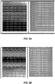
- FIGS. 2A and 2B illustrates the results obtained using the laser processing system 100 of FIG. 1 for processing or treating the sapphire substrate with the parameters indicated above. As shown, the edges are clean and there are no visible cracks. Equally satisfactory results were obtained for unpolished and polished samples.
- sample sapphire substrates of different thicknesses were processed with different processing operations (e.g., scribing, cutting, and drilling) using a Yb-doped QCW SM fiber laser at different duty cycles, pulse frequencies and speeds.
- processing operations e.g., scribing, cutting, and drilling
- Table I illustrates the parameters used for these processing operations.
- the QCW SM fiber laser at a wavelength in the range of about 1060 - 1070 nm.
- the single mode beam with a relatively small spot provides a high power density capable of breaking down the material.
- the peak power and average power may need to be higher as the material thickness increases, but the low duty cycle appears to be more of a key factor than peak power.
- a high-quality cut may be achieved at 900 W, 500 Hz and 3% duty cycle (i.e., average power of 27 W) with a speed of 50.8 cm/min (20 inches/min).
- the cutting speed may be doubled to 101.6 cm/min (40 inch/min) by increasing the pulse frequency to 1000 Hz.
- the quality of the cut may deteriorate in response to scaling up the laser power. Also, the quality may improve at shorter pulse widths (e.g., 50-100 microseconds) which may lead to a high-speed process. The longer pulses also provide high quality cuts, but increasing the duty cycle results in longer periods of time to complete the processing.
- sapphire substrates with a thickness between about 0.4 mm and 0.7 mm were processed using the following process and laser parameters: a Ytterbium (Yb) single mode laser; 1070 nm wavelength; 14 ⁇ m fiber core diameter; 60 mm collimating distance; 123 mm focal length; 28. 7 ⁇ m spot size; argon or nitrogen assist gas at 17.23671 bar (250 psi); and 1.5 mm nozzle orifice.
- Yb Ytterbium
- the following Table II shows the results of processing using the above parameters with different peak power, frequency, duty cycle, pulse width and cut speed.
- a QCW SM fiber laser with a wavelength in a range of 1060-1070 nm can be successfully used for cutting a sapphire substrate with minimal cracks and chipping.
- the 0. 7 mm thick substrate has better cut quality.
- the 0.4 mm thick substrate exhibits chips along the edge of the cuts; however, the chips are generally less than 40 microns, which is considered to be a high quality cut as known to one of ordinary skill.
- the laser processing method disclosed herein also appears to be sensitive to high frequencies with significant chipping occurring at higher frequencies.
- the quality of the cuts also depends on the duration of duty cycle with a lower the duty cycle improving the cut quality.
- Peak power above 1600 W with a duty cycle of up to 10% may not provide any visible advantages, but a duty cycle lower than 1 % may deteriorate the quality of cuts.
- a gas pressure range between 13.78937 bar to 20.68406 bar (200 and 300 psi) also improved the efficiency of the process in these examples.
- the beam spot size is generally between about 14 and 30 microns, and using a spot size lower than 14 micron generally does not substantially affect the quality and efficiency of the process.
- sapphire substrates with a thickness of 2. 7 mm were successfully cut using a multimode QCW fiber laser with a 50 micron fiber with the following parameters: 15 kW peak power; 450 W average power; 0.6 ms pulse width; 100 micron spot size; 50Hz repetition rate; 3 % duty cycle; 25.40 cm/min (10 ipm) speed; argon gas at 6.89469 bar (100 psi); a 1.5 mm nozzle diameter; and a 1mm standoff.
- the use of argon or helium as the assist gas was found to improve cutting efficiency, possibly because of the trace Ti found in sapphire.
- a multiple-beam laser processing system 200 may also be used to process sapphire.
- Multiple-beam laser processing may be performed on a sapphire substrate or workpiece 202 using both an assist laser beam 211 and a process laser beam 221 with different characteristics (e.g., wavelengths and/or pulse durations).
- the assist laser beam 211 is directed at a target location 208 on or within the workpiece 202 to modify a property of the sapphire (e.g., induce damage or increase temperature) such that absorption centers are formed in the sapphire.
- the process laser beam 221 is directed at the target location 208 and is coupled into the absorption centers formed in the sapphire to complete processing of the sapphire.
- the assist laser beam 211 and the process laser beam 221 individually are not capable of completely processing the sapphire workpiece but together (either simultaneously or sequentially) provide a synergy that enables processing.
- the illustrated embodiment of the multiple-beam laser processing system 200 includes an assist laser 210 for generating the assist laser beam 211 (e.g., a green laser of about 532 nm) and a process laser 220 for generating the process laser beam 221 (e.g., a QCW SM fiber laser of about 1060 to 1070 nm).
- the assist and process lasers 210, 220 are optically coupled to respective beam delivery systems 212, 222 for modifying the assist and process laser beams 211, 221, respectively, before combining the beams.
- the multiple-beam laser processing system 200 further includes a beam combiner 230, a focus lens 240, a laser processing head 260, and one or more reflectors or mirrors 252, 254, 256 for directing the assist and process laser beams 211, 221 as a combined laser beam 231 to the same target location 208 on or within a workpiece 202.
- the beams 211, 221 may also be combined such that the beams are directed to the same target location 208 at different times. Directing the laser beams 211, 221 simultaneously may include any amount of overlap between the bursts or pulses of the laser beams 211, 221 and does not necessarily require the laser beams to have the same burst or pulse duration.
- the assist laser beam 211 may start before or during the process laser beam 221.
- the laser beams 211, 221 may also be directed to the workpiece 202 at different times, for example, with the assist laser beam 211 before the process laser beam 221.
- the assist laser 210 may be a rare-earth-doped fiber laser such as a GLP Series pulsed green fiber laser available from IPG Photonics Corporation.
- the assist laser 210 may include diode pumped solid state (DPSS) lasers, excimer lasers, gas lasers, and other types of lasers known to those skilled in the art.
- the process laser 220 may also be a rare-earth-doped fiber laser such as a QCW Series single-mode ytterbium fiber laser available from IPG Photonics Corporation.
- the assist laser beam delivery system 212 may include a variable telescope to provide beam expansion and divergence control of the assist laser beam 211.
- the divergence of the assist laser beam 211 may be controlled to have an optimized numerical aperture (NA) to create substantially the same focal plane as the process laser beam 221 after the laser beams 211, 221 are combined.
- the process laser beam delivery system 222 may include a collimator such as, for example, a collimating lens with a focal length of 100 mm.
- the beam delivery systems 212, 222 may also include other optics for modifying and/or directing the laser light to the desired location. Such optics may include, without limitation, beam expanders, beam collimators, beam shaping lenses, reflectors, masks, beamsplitters and scanners (e.g., a galvanometer).
- the beam combiner 230 includes reflectors or mirrors 232, 234 for selectively reflecting the wavelengths of the assist and process laser beams 211, 221, respectively, such that the beams 211, 221 are directed along the same optical axis.
- the first mirror 232 is coated to reflect the wavelength of the process laser beam 221
- the second mirror 234 is coated on one side to reflect the wavelength of the process laser beam 221 and uncoated on the other side to allow at least a portion of the assist laser beam 211 to pass through.
- the second mirror 234 combines both beams 211, 221.
- the first mirror 232 may be IR coated and the second mirror 234 may be IR coated on one side and uncoated on the other side.
- the uncoated side of the second mirror 234 may still reflect a portion of the assist laser beam 211 to a beam dump 250.
- Other embodiments for the beam combiner 230 are also within the scope of the present disclosure.
- the mirrors 252, 254, 256 may be coated to reflect the desired wavelengths of the laser beams 211, 221.
- the mirrors 252, 254 reflecting the green laser beam may be 532 nm or green coated mirrors capable of reflecting the green assist laser beam 211 and the mirror 256 may be a dual IR-green coated mirror capable of reflecting both the green assist laser beam 211 and the IR process laser beam 221.
- the transmission of the multiple-beam laser processing system 200 may be 40% for the assist laser beam 211 and 90% for the process laser beam 221.
- the illustrated embodiment shows free space delivery using mirrors
- other optical components may also be used to deliver and/or combine the lasers.
- one or more fibers may be used to deliver the laser beams to the laser processing head 260.
- the lasers may be combined by focusing the lasers to the same location 208 on or within the workpiece 202.
- the focus lens 240 may be a singlet focusing lens such as, for example, a lens with an 88 mm focal length and coated for IR.
- the focus lens 240 may be capable of focusing the laser beams to a beam spot with a diameter or dimension in a range of about 30 to 40 ⁇ m.
- the beam delivery systems and focus lens 24 may be capable of focusing the lasers 211, 221 to an even smaller beam spot, for example, as small as 15 ⁇ m or smaller.
- the laser processing head 260 includes a gas assist nozzle 262 to direct a pressurized gaseous medium to the workpiece 202 together with the laser beams to facilitate laser processing, for example, when using a thermal cutting process where the gas helps to expel molten material.
- the gaseous medium may include, for example, oxygen (O 2 ).
- the gaseous medium may be an inert gas, such as nitrogen, argon or helium.
- the multiple laser beam processing method may also be performed using the same laser source to produce both the assist laser beam 211 and the process laser beam 221.
- an assist laser beam may be generated from a laser source with one set of parameters (e.g., a shorter wavelength and/or pulse duration) and a process laser beam may be generated from the same laser source with a different set of parameters (e.g., a longer wavelength and/or pulse duration).
- a single laser beam generated by a laser source may also be split and modified with different beam delivery systems to produce the assist laser beam and the process laser beam with distinct characteristics.
- laser processing systems and methods are capable of efficiently processing sapphire using a QCW SM fiber laser in a wavelength range of about 1060 - 1070 nm with reduced cutting edge defects, reduced thermal damage, and increased speeds.
Landscapes
- Engineering & Computer Science (AREA)
- Physics & Mathematics (AREA)
- Optics & Photonics (AREA)
- Plasma & Fusion (AREA)
- Mechanical Engineering (AREA)
- Laser Beam Processing (AREA)
- General Physics & Mathematics (AREA)
- Lasers (AREA)
Description
- The present disclosure relates to processing sapphire using lasers in a wavelength range of about 1060-1070 nm, as shown in the preamble of claims 1, 9 and 12 (see, for example
US 2012/255935 A1 ). - Hard materials such as sapphire (Al2O3) are used for many industrial applications such as optical windows, hard materials preventing abrasion, and buffer materials for semiconductor emitting device, and the like. Conventional mechanical methods for treating or processing sapphire substrates include diamond scribing and blade dicing. When using these methods, the low depth of the scribe can lead to breaking the substrate, which lowers production yields, for example, when manufacturing of LEDs. Other problems associated with blade dicing include formation of debris (which may require post-cutting cleaning), stress induced into the substrate, and the relatively large width of the cut known as kerf.
- Laser processing methods have been used in an effort to increase efficiency because they provide a noncontact process that is more efficient for high volume production. The laser scribed cutting depth may also be controlled to reduce stress on the wafer during the break process. Also, laser scribing facilitates precise positioning of scribes within a few microns of active features along with a narrow scribe width with fewer chippings. Thus, laser processing has overall advantages of increased throughput, low cost, ease of use, and high yields compared to traditional mechanical methods.
- Certain materials, however, present challenges when processing using lasers. The bandgap of sapphire, for example, is approximately 8eV, and under normal low intensity illumination, sapphire is optically transparent from 5000 nm to about 300 nm. Therefore, conventional laser processing of sapphire has used lasers that are more likely to be absorbed in sapphire, such as DUV and UV lasers operating in a wavelength range between about 157 and about 355 nm.
- One technique for laser processing of sapphire involves ablation, which is a vaporization of the material resulting from a combination of bulk heating of the material and avalanche ionization. Ultrafast lasers (e.g., picosecond and shorter pulse widths) and/or Q-switched pulse lasers with nanosecond pulse widths may be used to emit pulses with high peak power capable of ablating sapphire. The high intensity drives a nonlinear, multiphoton absorption process which excites electrons in the material and directly breaks bonds. However, high peak power may thermally damage the cut edge because the heat from the absorption of the laser beam has time to diffuse into the substrate.
- Another laser processing technique involves scribing and breaking along internal modification regions inside the sapphire. The output of a picoseconds laser, for example, may be focused inside the sapphire substrate creating cracks within the substrate without affecting the top and bottom surfaces. Once these cracks are produced, the individual pieces may be broken out from the substrate using mechanical means such as tape expansion. This two-step process, however, may be time consuming and cost inefficient.
- A further technique for laser processing materials with a low absorption coefficient includes water jet laser processing. Water jet laser processing involves focusing a laser beam into a hair-thin, low-pressure water jet, which then guides the laser beam onto the wafer. Water jet laser processing systems, such as the Laser-Microjet® system, may prevent heat damage and contamination but also involves a more complex and expensive system. A Q-switched Nd:YAG laser operating at 1064 nm and frequency-doubled Nd:YAG lasers operating at 532 nm are particularly adapted to the water jet-guided cutting technology.
- The existing techniques used for laser processing of sapphire discussed above suffer from some of the same drawbacks. In particular, the cost of pulsed lasers is high. Also, the wavelengths used in UV cutting require the use of crystals, which may have a short useful life and may present issues with the maintenance of these lasers. Although excimer lasers may be used, these lasers generally have large dimensions and low efficiency.
- Accordingly, a need exists for a system and method of laser cutting sapphire substrates at wavelengths of around 1060-1070 nm with reduced cutting edge defects and increased speeds in a time-effective and a cost-effective manner.
- Consistent with an embodiment, method is provided for laser processing a sapphire substrate. The method includes: periodically switching on a power source to pulse a continuous wave laser and emitting consecutive pulses of laser light, respectively, using single mode (SM) light from a single mode (SM) fiber laser, thereby operating the single mode (SM) fiber laser in a quasi-continuous wave ("QCW") mode so as to emit consecutive pulses of single mode (SM) laser light at a wavelength ranging between about 1060 nm and about 1070 nm; focusing the pulses of laser light at the sapphire substrate; and laser processing and treating, respectively, the sapphire substrate with the pulses of laser light, wherein the pulses of single mode (SM) light each having a pulse width ranging between about 50 microseconds and about 600 microseconds, wherein the laser is operated with a duty cycle ranging between about 1% and about 10% and wherein the laser processes the sapphire substrate with the pulses of laser light so as to penetrate through it.
- Consistent with another embodiment, laser processing system is provided for laser processing sapphire substrates. The laser processing system includes a fiber laser configured to operate in a quasi continuous wave ("QCW") mode and wherein the fiber laser includes a single mode (SM) fiber laser to emit consecutive pulses of single mode (SM) laser light at a wavelength between about 1060 nm and about 1070 nm and a controller coupled to the fiber laser for periodically switching power to the SM fiber laser to pulse the fiber laser in the QCW mode with a duty cycle ranging between about 1 % and about 10%. The controller is configured to periodically switch power to the SM fiber laser to emit pulses each having a pulse width which ranges between about 50 microseconds and about 600 microseconds. The laser processing system also includes a focus lens configured to focus the laser light on the sapphire substrate so as to process the sapphire substrate, a laser head configured to direct the focused laser light to the sapphire substrate and including a nozzle for delivering an inert gas to the sapphire substrate with the laser light, and a gas delivery system configured to deliver the inert gas into the laser head.
- Consistent with a further embodiment, a multiple-beam laser processing system is provided for processing a sapphire substrate. The multiple-beam laser processing system includes: an assist laser for generating an assist laser beam with a wavelength and a pulse duration such that the sapphire substrate is sufficiently absorptive of the assist laser beam to modify a property of the sapphire substrate; a single mode (SM) quasi continuous wave (QCW) fiber laser for generating a process laser beam with a wavelength between about 1060 nm and about 1070 nm, wherein the wavelength of the assist laser beam is less than the wavelength of the single mode process laser beam; and a beam combiner for directing the assist laser beam and the single mode (SM) process laser beam at a target location on the workpiece such that the assist laser beam modifies a property of the sapphire substrate at the target location forming absorption centers and such that the single mode (SM) process laser beam is coupled into the absorption centers formed in the sapphire substrate at the target location to complete processing of the sapphire substrate at the target location.
- These and other features and advantages will be better understood by reading the following detailed description, taken together with the drawings wherein:
-
FIG. 1 is a schematic diagram of a laser processing system for cutting a sapphire material using a quasi-continuous wave (QCW) laser system, consistent with an embodiment of the present disclosure. -
FIGS. 2A and 2B are images illustrating a sapphire substrate with a scribe line formed using a QCW laser system, consistent with an embodiment of the present disclosure. -
FIG. 3 is a schematic diagram of a multiple-beam laser processing system, consistent with another embodiment of the present disclosure. - Laser processing of sapphire, consistent with embodiments of the present disclosure, is performed using a continuous wave laser operating in a quasi-continuous wave (QCW) mode to emit consecutive laser light pulses in a wavelength range of about 1060 nm to 1070 nm (hereinafter "QCW laser"). Laser processing of sapphire using a QCW laser is performed with a lower duty cycle between 1% and 10% and in an inert gas atmosphere such as argon or helium. Laser processing of sapphire using a QCW laser further includes the use of an assist laser having a shorter wavelength and/or pulse duration to modify a property of the sapphire to form absorption centers, which facilitate coupling of the laser light pulses of the QCW laser into the sapphire.
- Laser processing using the QCW laser, consistent with embodiments described herein, may include drilling, cutting and/or scribing the sapphire substrate. Sapphire is a crystalline form of alumina (Al2O3), which is transparent to light wavelengths between about 170 nm and 5300 nm, five (5) times stronger than glass, and nine (9) on the Mohs scale of hardness. Sapphire is also a good electrical insulator and has a high thermal conductivity. Sapphire may be particularly advantageous in manufacturing of blue and green light emitting diodes ("LED"). Sapphire also has potential for replacing the existing glass covering the screen for a mobile device including, but not limited to, telephones, cameras, computers and the like. Thus, the laser processing systems and methods described herein may be used to cut sapphire substrates to a desired shape for use in manufacturing photonic devices, screens and other products incorporating sapphire.
- As used herein, "absorption center" refers to a location in a non-absorptive material where the properties of the material have been modified (e.g., craters, roughening, optical damage, internal material defects, color centers, bulk material property changes, or increased temperature) such that light is more likely to be absorbed as compared to an unmodified region of the material. As used herein, "wavelength" refers to an approximate emission wavelength of a laser and may encompass a band or range of wavelengths around the stated wavelength. As used herein, "ultraviolet (UV) spectral range" refers to a spectral range of 10 nm to 380 nm, "visible spectral range" refers to a spectral range of 380 nm to 700 nm, and "infra-red spectral range" refers to a spectral range of 700 nm to 10.6 µm.
- Referring to
FIG. 1 , an embodiment of alaser processing system 100 is described for processing aworkpiece 102, such as a sapphire substrate, using a focused laser beam. Theworkpiece 102 may also be made from other large bandgap and/or transparent materials including, without limitation, aluminum diamond, gallium nitride, silicon carbide, zinc selenide, silicon, silicon nitride, aluminum nitride, gallium nitride on sapphire, and glass (e.g., fused quartz or silica). Although the example embodiments described herein mostly relate to laser treatment or processing of sapphire, at least some of these other large bandgap materials can be successfully treated with the disclosed laser processing systems. - In the illustrated embodiment, the
laser processing system 100 includes a QCW single mode (SM)fiber laser 110 emitting a single mode, divergencelimited laser beam 111 from the downstream end of a processingpassive fiber 112. TheQCW fiber laser 110 may range in power from 500 W to 50 kW and may have a monolithic, entirely solid state, fiber-to-fiber design that does not require mirrors or optics to align or adjust. The QCW fiber laser 10 may also be modular, built from multiple laser units, each one generating hundreds of watts of output power. This also allows the laser system to incorporate reserve modules and power margins. The QCW SM fiber laser may include, for example, a QCW SM ytterbium fiber laser with an emission wavelength of about 1070 nm, such as the QCW series available from IPG Photonics Corporation. In other embodiments, the laser may include a fiber disc laser or a rod laser such as a Nd: YAO laser. Multi-mode lasers may also be used. - The
laser processing system 100 also includes acollimator 130 to collimate thebeam 111 and a beam bender orreflector 132 to direct thebeam 111 to afocus lens 140. Thefocus lens 140 may focus thebeam 111 to a relatively small spot size, for example, in a range of about 14-30 µm. Alternatively or additionally, other optics may also be used for modifying and/or directing the laser light to the desired location. Such optics may include, without limitation, beam expanders, beam collimators, beam shaping lenses, reflectors, masks, beamsplitters and scanners (e.g., a galvanometer). - The
laser processing system 100 further includes a laser head including anozzle 160 coupled to agas delivery system 162. Thegas delivery system 162 may provide a stream of inert gas, such as nitrogen, argon or helium, to thenozzle 160 close to the work area when processing theworkpiece 102. The gas may be delivered with a pressure in a range of about 6.89469 bar to 20.68406 bar (100 to 300 psi). The presence of the inert atmosphere improves the efficiency of the laser processing. - The
laser processing system 100 further includes atranslation stage 170 configured to impart a translational motion to theworkpiece 102 in one or more axes or dimensions, thereby allowing theworkpiece 102 to move relative to the focused laser beam. Thetranslation stage 170 may be operated manually or may receive commands from acontroller 172. Alternatively, thelaser 110 may be moved and displaced relative to theworkpiece 102 to be processed. Thecontroller 172 includes processing circuitry, such as a central processing unit ("CPU"), to communicate withtranslation stage 170. - The QWC
SM fiber laser 110 includes apump source 114 operable to be switched on for time intervals having a duration long enough to operate the laser as close to its steady state as possible, i.e. the laser is optically in the state of continuous-wave operation, also referred to as a quasi-continuous wave (QCW) mode. Thecontroller 172 may be used to control thepump source 114. The percentage of time the laser is switched on, i.e., the duty cycle, is selected to reduce the heating and heat related problems. Thecontroller 172 may control thepump source 114 to have a duty cycle in a range of about 1 % to 10%. Therefore, the QCWSM fiber laser 110 operating in the QCW mode may have higher output peak powers and lower average powers. - In one example, a sapphire substrate with a thickness of 0.7 mm was processed using the following process and laser parameters: a Ytterbium (Yb) single mode laser; 1070 nm wavelength; 14 µm fiber core diameter; 60 mm collimating distance; 123 mm focal length; 28.7 µm spot size; 900 W peak power; 87.5 µs pulse duration; 400 Hz pulse frequency; 78.7 mJ pulse energy; argon or nitrogen assist gas at 17.23671 bar (250 psi); 0.5 mm nozzle stand off; 1.5 mm nozzle orifice; and 8.46 mm/s cutting speed.
-
FIGS. 2A and 2B illustrates the results obtained using thelaser processing system 100 ofFIG. 1 for processing or treating the sapphire substrate with the parameters indicated above. As shown, the edges are clean and there are no visible cracks. Equally satisfactory results were obtained for unpolished and polished samples. - In another example, sample sapphire substrates of different thicknesses (e.g., 0.015 in. and 0.040 in.) were processed with different processing operations (e.g., scribing, cutting, and drilling) using a Yb-doped QCW SM fiber laser at different duty cycles, pulse frequencies and speeds. The following Table I illustrates the parameters used for these processing operations.
Table I Sapphire cm (inches) Process Power (W) Frequency (Hz) Duty Cycle(%) Speed (cm per minute ("cm/min") (inches per minute ("ipm")) Assist gas 0.0381 (0.015") Scribing 285 3500 20 1066.8 (420) 2068.41 mbar (30 psi) N2 0.0381 (0.015") Cutting 285 2000 40 101.6 (40) 2068.41 mbar (30 psi) N2 0.0381 (0.015") Drilling 285 2000 40 <25.4 (<10) 2068.41 mbar (30 psi) N2 0.1060 (0.040") Scribing 285 2500 25 914.4 (360) 2068.41 mbar (30 psi) N2 0.1060 (0.040") Scribing 285 500 30 76.2 (30) 2068.41 mbar (30 psi) N2 0.1060 (0.040") Drilling 285 2000 30 <25.4 (<10) 2068.41 mbar (30 psi) N2 - In this example, scribing of the 0.0381 cm (0.015")-thick sapphire sample with a laser beam at 285 W removed about 30% of the thickness of the sample at a speed of about 1066.8 cm/min (420 ipm). Cutting the 0.0381 cm (0.015")-thick sapphire sample was also effective at a 285 W power and speed of about 101.6 cm/min (40 ipm). Drilling circular holes in the sapphire samples was successful at relatively low speeds. The same processing operations were also successfully performed on the 0.1016 cm (0.040") thick wafer.
- QCW SM fiber laser at a wavelength in the range of about 1060 - 1070 nm. The single mode beam with a relatively small spot provides a high power density capable of breaking down the material. Better processing appears to be possible at lower duty cycles, i.e., low average powers. The peak power and average power may need to be higher as the material thickness increases, but the low duty cycle appears to be more of a key factor than peak power.
- In a further example, a high-quality cut may be achieved at 900 W, 500 Hz and 3% duty cycle (i.e., average power of 27 W) with a speed of 50.8 cm/min (20 inches/min). In this example, the cutting speed may be doubled to 101.6 cm/min (40 inch/min) by increasing the pulse frequency to 1000 Hz. The quality of the cut may deteriorate in response to scaling up the laser power. Also, the quality may improve at shorter pulse widths (e.g., 50-100 microseconds) which may lead to a high-speed process. The longer pulses also provide high quality cuts, but increasing the duty cycle results in longer periods of time to complete the processing.
- In yet another example, sapphire substrates with a thickness between about 0.4 mm and 0.7 mm were processed using the following process and laser parameters: a Ytterbium (Yb) single mode laser; 1070 nm wavelength; 14 µm fiber core diameter; 60 mm collimating distance; 123 mm focal length; 28. 7 µm spot size; argon or nitrogen assist gas at 17.23671 bar (250 psi); and 1.5 mm nozzle orifice. The following Table II shows the results of processing using the above parameters with different peak power, frequency, duty cycle, pulse width and cut speed.
Table II # Material Peak Power (W) Frequency (Hz) Duty Cycle (%) Pulse Width (ms) Cut Speed (cm/min) [Inch/min] Comments 1 0.4mm polished 400 160 2,75 0,171 30.48 [12] Very fine powdery dross. The dross rubs off easily just by wiping it. Some chipping and cracks. Less than <30 microns at random places. 2 0.7mm unpolished 900 400 3,5 0,0875 40.64-50.8 [16-20] Very fine powdery dross. The dross rubs off easily just by wiping it. No cracking but some chipping. Less than <40 microns at random places. 3 0.7mm unpolished 750 300 3,5 0,116 30.48 [12] Very fine powdery dross. The dross rubs off easily just by wiping it. No cracking but some chipping. Less than <40 microns at random places. Optics used is 200Focal/120mm collimator. - Based on the foregoing, a QCW SM fiber laser with a wavelength in a range of 1060-1070 nm can be successfully used for cutting a sapphire substrate with minimal cracks and chipping. In the above example, the 0. 7 mm thick substrate has better cut quality. The 0.4 mm thick substrate exhibits chips along the edge of the cuts; however, the chips are generally less than 40 microns, which is considered to be a high quality cut as known to one of ordinary skill. The laser processing method disclosed herein also appears to be sensitive to high frequencies with significant chipping occurring at higher frequencies. The quality of the cuts also depends on the duration of duty cycle with a lower the duty cycle improving the cut quality. Peak power above 1600 W with a duty cycle of up to 10% may not provide any visible advantages, but a duty cycle lower than 1 % may deteriorate the quality of cuts. A gas pressure range between 13.78937 bar to 20.68406 bar (200 and 300 psi) also improved the efficiency of the process in these examples. The beam spot size is generally between about 14 and 30 microns, and using a spot size lower than 14 micron generally does not substantially affect the quality and efficiency of the process.
- In a further example, sapphire substrates with a thickness of 2. 7 mm were successfully cut using a multimode QCW fiber laser with a 50 micron fiber with the following parameters: 15 kW peak power; 450 W average power; 0.6 ms pulse width; 100 micron spot size; 50Hz repetition rate; 3 % duty cycle; 25.40 cm/min (10 ipm) speed; argon gas at 6.89469 bar (100 psi); a 1.5 mm nozzle diameter; and a 1mm standoff. The use of argon or helium as the assist gas was found to improve cutting efficiency, possibly because of the trace Ti found in sapphire.
- Referring to
FIG. 3 , a multiple-beamlaser processing system 200 may also be used to process sapphire. Multiple-beam laser processing may be performed on a sapphire substrate orworkpiece 202 using both anassist laser beam 211 and aprocess laser beam 221 with different characteristics (e.g., wavelengths and/or pulse durations). The assistlaser beam 211 is directed at atarget location 208 on or within theworkpiece 202 to modify a property of the sapphire (e.g., induce damage or increase temperature) such that absorption centers are formed in the sapphire. Theprocess laser beam 221 is directed at thetarget location 208 and is coupled into the absorption centers formed in the sapphire to complete processing of the sapphire. The assistlaser beam 211 and theprocess laser beam 221 individually are not capable of completely processing the sapphire workpiece but together (either simultaneously or sequentially) provide a synergy that enables processing. - The illustrated embodiment of the multiple-beam
laser processing system 200 includes anassist laser 210 for generating the assist laser beam 211 (e.g., a green laser of about 532 nm) and aprocess laser 220 for generating the process laser beam 221 (e.g., a QCW SM fiber laser of about 1060 to 1070 nm). The assist andprocess lasers beam delivery systems process laser beams laser processing system 200 further includes abeam combiner 230, afocus lens 240, alaser processing head 260, and one or more reflectors or mirrors 252, 254, 256 for directing the assist andprocess laser beams laser beam 231 to thesame target location 208 on or within aworkpiece 202. - Although the illustrated embodiment shows the assist and
process laser beams beams same target location 208 at different times. Directing thelaser beams laser beams laser beam 211 may start before or during theprocess laser beam 221. Thelaser beams workpiece 202 at different times, for example, with theassist laser beam 211 before theprocess laser beam 221. - In the illustrated embodiment, the
assist laser 210 may be a rare-earth-doped fiber laser such as a GLP Series pulsed green fiber laser available from IPG Photonics Corporation. In other embodiments, theassist laser 210 may include diode pumped solid state (DPSS) lasers, excimer lasers, gas lasers, and other types of lasers known to those skilled in the art. Theprocess laser 220 may also be a rare-earth-doped fiber laser such as a QCW Series single-mode ytterbium fiber laser available from IPG Photonics Corporation. - The assist laser
beam delivery system 212 may include a variable telescope to provide beam expansion and divergence control of theassist laser beam 211. In particular, the divergence of theassist laser beam 211 may be controlled to have an optimized numerical aperture (NA) to create substantially the same focal plane as theprocess laser beam 221 after thelaser beams beam delivery system 222 may include a collimator such as, for example, a collimating lens with a focal length of 100 mm. Alternatively or additionally, thebeam delivery systems - In the illustrated embodiment, the
beam combiner 230 includes reflectors or mirrors 232, 234 for selectively reflecting the wavelengths of the assist andprocess laser beams beams first mirror 232 is coated to reflect the wavelength of theprocess laser beam 221, and thesecond mirror 234 is coated on one side to reflect the wavelength of theprocess laser beam 221 and uncoated on the other side to allow at least a portion of theassist laser beam 211 to pass through. Thus, thesecond mirror 234 combines bothbeams assist laser beam 211 and an IRprocess laser beam 221, for example, thefirst mirror 232 may be IR coated and thesecond mirror 234 may be IR coated on one side and uncoated on the other side. The uncoated side of thesecond mirror 234 may still reflect a portion of theassist laser beam 211 to abeam dump 250. Other embodiments for thebeam combiner 230 are also within the scope of the present disclosure. - The
mirrors laser beams assist laser beam 211 and an IRprocess laser beam 221, for example, themirrors assist laser beam 211 and themirror 256 may be a dual IR-green coated mirror capable of reflecting both the greenassist laser beam 211 and the IRprocess laser beam 221. In one embodiment, the transmission of the multiple-beamlaser processing system 200 may be 40% for theassist laser beam 211 and 90% for theprocess laser beam 221. - Although the illustrated embodiment shows free space delivery using mirrors, other optical components may also be used to deliver and/or combine the lasers. For example, one or more fibers may be used to deliver the laser beams to the
laser processing head 260. In this embodiment, the lasers may be combined by focusing the lasers to thesame location 208 on or within theworkpiece 202. - The
focus lens 240 may be a singlet focusing lens such as, for example, a lens with an 88 mm focal length and coated for IR. Thefocus lens 240 may be capable of focusing the laser beams to a beam spot with a diameter or dimension in a range of about 30 to 40 µm. In other embodiments, the beam delivery systems and focus lens 24 may be capable of focusing thelasers - In the illustrated embodiment, the
laser processing head 260 includes a gas assist nozzle 262 to direct a pressurized gaseous medium to theworkpiece 202 together with the laser beams to facilitate laser processing, for example, when using a thermal cutting process where the gas helps to expel molten material. The gaseous medium may include, for example, oxygen (O2). In other embodiments, the gaseous medium may be an inert gas, such as nitrogen, argon or helium. - Although the illustrated embodiments show
multiple lasers assist laser beam 211 and theprocess laser beam 221, the multiple laser beam processing method may also be performed using the same laser source to produce both theassist laser beam 211 and theprocess laser beam 221. For example, an assist laser beam may be generated from a laser source with one set of parameters (e.g., a shorter wavelength and/or pulse duration) and a process laser beam may be generated from the same laser source with a different set of parameters (e.g., a longer wavelength and/or pulse duration). A single laser beam generated by a laser source may also be split and modified with different beam delivery systems to produce the assist laser beam and the process laser beam with distinct characteristics. - Accordingly, laser processing systems and methods, as described herein, are capable of efficiently processing sapphire using a QCW SM fiber laser in a wavelength range of about 1060 - 1070 nm with reduced cutting edge defects, reduced thermal damage, and increased speeds.
- While the principles of the invention have been described herein, it is to be understood by those skilled in the art that this description is made only by way of example and not as a limitation as to the scope of the invention. Other embodiments are contemplated within the scope of the present invention in addition to the example embodiments shown and described herein. Modifications and substitutions by one of ordinary skill in the art are considered to be within the scope of the present invention, which is not to be limited except by the following claims.
Claims (14)
- A method for laser processing a sapphire substrate (102), including emitting consecutive pulses of laser light, focusing the light pulses at the sapphire substrate (102), and laser treating the sapphire substrate (102),
characterized in that the method comprising:using single mode (SM) light from a single mode (SM) fiber laser (110, 112);operating the single mode (SM) fiber laser (110, 112) in a quasi-continuous wave ("QCW") mode so as to emit consecutive pulses of single mode (SM) laser light at a wavelength ranging between about 1060 nm and about 1070 nm, the pulses of single mode (SM) light each having a pulse width ranging between about 50 microseconds and about 600 microseconds, wherein the laser is operated with a duty cycle ranging between about 1% and about 10%;
andthe laser processing the sapphire substrate (102) with the pulses of laser light so as to penetrate through it. - The method of claim 1 further comprising supplying inert gas in a vicinity of the sapphire substrate (102).
- The method of claim 2, wherein the inert gas is selected from the group consisting of argon and helium.
- The method of claim 1, wherein laser processing the sapphire substrate (102) is selected from the group consisting of cutting, scribing, and drilling
and/or
wherein laser processing includes cutting with a speed between about 25.4 cm and 101.6 cm (10 and 40 inches) per minute, and wherein the sapphire substrate has a thickness between about 0.1 and about 1 mm. - The method of claim 1, wherein the laser (110, 112) is an ytterbium fiber laser.
- The method of claim 1 further comprising focusing assist laser light at the sapphire substrate (102), wherein the assist laser light modifies a property of the sapphire (102) to form absorption centers, and wherein the pulses of laser light from the laser couple into the absorption centers to facilitate the laser processing.
- The method of claim 6, wherein the assist laser light is generated by a green fiber laser configured to emit assist laser light at a wavelength of about 532 nm
and/or
wherein the assist laser light is directed at the sapphire substrate (102) simultaneously with the pulses of laser light from the laser. - The method of claim 6, wherein the assist laser light is generated by a green fiber laser configured to emit assist laser light at a wavelength of about 532 nm and wherein the green fiber laser is configured to emit the assist laser light with a pulse duration of 1 ns.
- A laser processing system (100) for laser processing sapphire substrates (102), comprising
a focus lens (140) configured to focus the laser light on the sapphire substrate (102) so as to process the sapphire substrate (102);
a laser head configured to direct the focused laser light to the sapphire substrate (102) and including a nozzle (160) for delivering an inert gas to the sapphire substrate (102) with the laser light; and being characterized in that the laser processing system comprises a fiber laser (110, 112) configured to operate in a quasi continuous wave ("QCW") mode and wherein the fiber laser (110, 112) includes a single mode (SM) fiber laser to emit consecutive pulses of single mode (SM) laser light at a wavelength between about 1060 nm and about 1070 nm;
a controller (172) coupled to the fiber laser for periodically switching power to the fiber laser (110, 112) to pulse the fiber laser (110, 112) in the QCW mode with a duty cycle ranging between about 1% and about 10%;
wherein the fiber laser (110, 112) includes a single mode (SM) fiber laser and wherein the controller (172) is configured to periodically switch power to the SM fiber laser to emit pulses each having a pulse width which ranges between about 50 microseconds and about 600 microseconds; and
a gas delivery system (162) configured to deliver the inert gas into the laser head. - The laser processing system (100) of claim 9, wherein the fiber laser (110, 112) includes a single mode (SM) fiber laser
and/or
wherein the fiber laser (110, 112) includes an ytterbium fiber laser. - The laser processing system (100) of claim 9, wherein the inert gas is selected from the group consisting of argon and helium.
- A multiple-beam laser processing system (200) for processing a sapphire substrate (202), the multiple-beam laser processing system (200) comprising:an assist laser (210) for generating an assist laser beam (211) with a wavelength and a pulse duration such that the sapphire substrate (202) is sufficiently absorptive of the assist laser beam (211) to modify a property of the sapphire substrate (202); and being characterized bya single mode (SM) quasi continuous wave (QCW) process fiber laser (220) for generating a process laser beam (221) with a wavelength between about 1060 nm and about 1070 nm, wherein the wavelength of the assist laser beam is less than the wavelength of the single mode (SM) process laser beam; anda beam combiner for directing the assist laser beam (211) and the single mode (SM) process laser beam (221) at a target location (208) on the workpiece (202) such that the assist laser beam (211) modifies a property of the sapphire substrate (202) at the target location (208) forming absorption centers and such that the single mode (SM) process laser beam (221) is coupled into the absorption centers formed in the sapphire substrate (202) at the target location (208) to complete processing of the sapphire substrate (202) at the target location (208).
- The multiple-beam laser processing system (200) of claim 12 further including a focus lens for focusing the assist laser beam (211) and the process laser beam (221) at the target location (208)
and/or
wherein the assist laser (210) is a green fiber laser for generating a green assist laser beam (211) with a wavelength of about 532 nm. - The multiple-beam laser processing system (200) of claim 12, wherein the QCW fiber laser is a QCW single-mode ytterbium fiber laser
and/or
wherein the multiple-beam laser processing system (200) further comprising an assist laser beam (211) delivery system for controlling divergence of the assist laser beam (211) such that the assist laser beam (211) and the process laser beam (221) have the same focal plane.
Applications Claiming Priority (2)
| Application Number | Priority Date | Filing Date | Title |
|---|---|---|---|
| US201361770816P | 2013-02-28 | 2013-02-28 | |
| PCT/US2014/019460 WO2014134470A1 (en) | 2013-02-28 | 2014-02-28 | Laser system and method for processing sapphire |
Publications (3)
| Publication Number | Publication Date |
|---|---|
| EP2961559A1 EP2961559A1 (en) | 2016-01-06 |
| EP2961559A4 EP2961559A4 (en) | 2016-09-07 |
| EP2961559B1 true EP2961559B1 (en) | 2020-05-20 |
Family
ID=51428844
Family Applications (1)
| Application Number | Title | Priority Date | Filing Date |
|---|---|---|---|
| EP14757006.3A Active EP2961559B1 (en) | 2013-02-28 | 2014-02-28 | Laser systems and method for processing sapphire |
Country Status (6)
| Country | Link |
|---|---|
| EP (1) | EP2961559B1 (en) |
| JP (1) | JP6392789B2 (en) |
| KR (1) | KR102176313B1 (en) |
| CN (1) | CN105142853B (en) |
| TW (1) | TWI632997B (en) |
| WO (1) | WO2014134470A1 (en) |
Cited By (1)
| Publication number | Priority date | Publication date | Assignee | Title |
|---|---|---|---|---|
| EP4234150A1 (en) * | 2022-02-28 | 2023-08-30 | Bystronic Laser AG | Laser cutting method and machine |
Families Citing this family (20)
| Publication number | Priority date | Publication date | Assignee | Title |
|---|---|---|---|---|
| US9102011B2 (en) | 2013-08-02 | 2015-08-11 | Rofin-Sinar Technologies Inc. | Method and apparatus for non-ablative, photoacoustic compression machining in transparent materials using filamentation by burst ultrafast laser pulses |
| US9517929B2 (en) | 2013-11-19 | 2016-12-13 | Rofin-Sinar Technologies Inc. | Method of fabricating electromechanical microchips with a burst ultrafast laser pulses |
| US11053156B2 (en) | 2013-11-19 | 2021-07-06 | Rofin-Sinar Technologies Llc | Method of closed form release for brittle materials using burst ultrafast laser pulses |
| US10005152B2 (en) | 2013-11-19 | 2018-06-26 | Rofin-Sinar Technologies Llc | Method and apparatus for spiral cutting a glass tube using filamentation by burst ultrafast laser pulses |
| US10252507B2 (en) | 2013-11-19 | 2019-04-09 | Rofin-Sinar Technologies Llc | Method and apparatus for forward deposition of material onto a substrate using burst ultrafast laser pulse energy |
| US10144088B2 (en) | 2013-12-03 | 2018-12-04 | Rofin-Sinar Technologies Llc | Method and apparatus for laser processing of silicon by filamentation of burst ultrafast laser pulses |
| US9844833B2 (en) * | 2014-01-30 | 2017-12-19 | Apple Inc. | System and method for laser cutting sapphire using multiple gas media |
| US9938187B2 (en) | 2014-02-28 | 2018-04-10 | Rofin-Sinar Technologies Llc | Method and apparatus for material processing using multiple filamentation of burst ultrafast laser pulses |
| US9757815B2 (en) | 2014-07-21 | 2017-09-12 | Rofin-Sinar Technologies Inc. | Method and apparatus for performing laser curved filamentation within transparent materials |
| CN107148324A (en) * | 2014-08-28 | 2017-09-08 | Ipg光子公司 | Multiple laser systems and methods for dicing and post-dicing machining of hard dielectric materials |
| WO2016114934A1 (en) | 2015-01-13 | 2016-07-21 | Rofin-Sinar Technologies Inc. | Method and system for scribing brittle material followed by chemical etching |
| CN104959734B (en) * | 2015-07-06 | 2017-01-18 | 武汉华工激光工程有限责任公司 | Method for laser cutting of ink screen printing sapphire |
| CN105479009B (en) * | 2016-02-02 | 2017-09-29 | 深圳光韵达光电科技股份有限公司 | A kind of preparation method of SMT template surfaces super-drainage structure |
| JP6604891B2 (en) * | 2016-04-06 | 2019-11-13 | 株式会社ディスコ | Wafer generation method |
| JP2018094777A (en) | 2016-12-12 | 2018-06-21 | ダイセルポリマー株式会社 | Sealing method |
| JP6781649B2 (en) * | 2017-03-13 | 2020-11-04 | 株式会社ディスコ | Laser processing equipment |
| US11385420B2 (en) | 2017-12-29 | 2022-07-12 | Nanjing Casela Technologies Corporation Limited | Photon source comprising a plurality of optical sources and an optical shell to receive the light emitted by the optical source |
| JP2020145345A (en) * | 2019-03-07 | 2020-09-10 | 株式会社フジクラ | Fiber laser control device and control method |
| CN115302112A (en) * | 2022-08-02 | 2022-11-08 | 山东理工大学 | A femtosecond laser high-efficiency non-destructive precision scribing method and device for solar cells |
| CN119747916B (en) * | 2025-01-22 | 2025-07-08 | 青岛华芯晶电科技有限公司 | Damage control method and system for sapphire wafer cutting |
Citations (1)
| Publication number | Priority date | Publication date | Assignee | Title |
|---|---|---|---|---|
| JPS56169347A (en) * | 1980-05-31 | 1981-12-26 | Toshiba Corp | Laser scribing device |
Family Cites Families (14)
| Publication number | Priority date | Publication date | Assignee | Title |
|---|---|---|---|---|
| JPS6380989A (en) * | 1986-09-22 | 1988-04-11 | Mazda Motor Corp | Cutting method for silicon nitride sintered material |
| KR100853254B1 (en) * | 2001-03-12 | 2008-08-21 | 일렉트로 싸이언티픽 인더스트리이즈 인코포레이티드 | Kwazai-CW diode-pumped, solid-state laser system and how to use this system |
| JP4209615B2 (en) * | 2001-12-28 | 2009-01-14 | 株式会社ニデック | Laser processing equipment |
| JP2004114075A (en) * | 2002-09-25 | 2004-04-15 | Laser Solutions Co Ltd | Laser beam machining device |
| JP4247383B2 (en) * | 2003-08-28 | 2009-04-02 | 独立行政法人産業技術総合研究所 | Fine ablation processing method of transparent material |
| US20050087522A1 (en) * | 2003-10-24 | 2005-04-28 | Yunlong Sun | Laser processing of a locally heated target material |
| CN1256754C (en) * | 2003-10-28 | 2006-05-17 | 中国科学院上海光学精密机械研究所 | Preparation method of color center sapphire substrate |
| US7726532B2 (en) * | 2004-10-25 | 2010-06-01 | Mitsuboshi Diamond Industrial Co., Ltd. | Method and apparatus for forming cracks |
| US8624157B2 (en) * | 2006-05-25 | 2014-01-07 | Electro Scientific Industries, Inc. | Ultrashort laser pulse wafer scribing |
| US7633979B2 (en) * | 2008-02-12 | 2009-12-15 | Pavilion Integration Corporation | Method and apparatus for producing UV laser from all-solid-state system |
| WO2011071886A1 (en) * | 2009-12-07 | 2011-06-16 | J.P. Sercel Associates, Inc. | Laser machining and scribing systems and methods |
| JP5595805B2 (en) * | 2010-06-28 | 2014-09-24 | 株式会社メガオプト | Laser equipment |
| JP5435500B2 (en) * | 2010-12-24 | 2014-03-05 | 古河電気工業株式会社 | Semiconductor laser driving circuit and optical fiber pulse laser device |
| US8933367B2 (en) * | 2011-02-09 | 2015-01-13 | Sumitomo Electric Industries, Ltd. | Laser processing method |
-
2014
- 2014-02-28 KR KR1020157025917A patent/KR102176313B1/en active Active
- 2014-02-28 JP JP2015560354A patent/JP6392789B2/en active Active
- 2014-02-28 WO PCT/US2014/019460 patent/WO2014134470A1/en not_active Ceased
- 2014-02-28 CN CN201480011223.6A patent/CN105142853B/en active Active
- 2014-02-28 EP EP14757006.3A patent/EP2961559B1/en active Active
- 2014-03-03 TW TW103106983A patent/TWI632997B/en active
Patent Citations (1)
| Publication number | Priority date | Publication date | Assignee | Title |
|---|---|---|---|---|
| JPS56169347A (en) * | 1980-05-31 | 1981-12-26 | Toshiba Corp | Laser scribing device |
Cited By (1)
| Publication number | Priority date | Publication date | Assignee | Title |
|---|---|---|---|---|
| EP4234150A1 (en) * | 2022-02-28 | 2023-08-30 | Bystronic Laser AG | Laser cutting method and machine |
Also Published As
| Publication number | Publication date |
|---|---|
| KR102176313B1 (en) | 2020-11-09 |
| TWI632997B (en) | 2018-08-21 |
| TW201446453A (en) | 2014-12-16 |
| JP2016514055A (en) | 2016-05-19 |
| WO2014134470A1 (en) | 2014-09-04 |
| EP2961559A1 (en) | 2016-01-06 |
| CN105142853B (en) | 2017-07-04 |
| CN105142853A (en) | 2015-12-09 |
| EP2961559A4 (en) | 2016-09-07 |
| KR20150119941A (en) | 2015-10-26 |
| JP6392789B2 (en) | 2018-09-19 |
Similar Documents
| Publication | Publication Date | Title |
|---|---|---|
| US11819949B2 (en) | Multi-laser system and method for cutting and post-cut processing hard dielectric materials | |
| US11565350B2 (en) | System and method for laser beveling and/or polishing | |
| US10286487B2 (en) | Laser system and method for processing sapphire | |
| US10343237B2 (en) | System and method for laser beveling and/or polishing | |
| KR102176313B1 (en) | Laser system and method for processing sapphire | |
| US9764427B2 (en) | Multi-laser system and method for cutting and post-cut processing hard dielectric materials | |
| US9956646B2 (en) | Multiple-beam laser processing using multiple laser beams with distinct wavelengths and/or pulse durations | |
| JP6422033B2 (en) | Laser-based machining method and apparatus for sheet-like substrates using laser beam focal lines | |
| TW201143947A (en) | Laser machining and scribing systems and methods | |
| CN103567630A (en) | Laminated-substrate processing method and processing apparatus | |
| JP2011011972A (en) | Apparatus for cutting brittle material and method of cutting brittle material | |
| KR20020080355A (en) | Energy-efficient, laser-based method and system for processing target materal | |
| EP2943973B1 (en) | Thermal processing by transmission of mid infra-red laser light through semiconductor substrate |
Legal Events
| Date | Code | Title | Description |
|---|---|---|---|
| PUAI | Public reference made under article 153(3) epc to a published international application that has entered the european phase |
Free format text: ORIGINAL CODE: 0009012 |
|
| 17P | Request for examination filed |
Effective date: 20150907 |
|
| AK | Designated contracting states |
Kind code of ref document: A1 Designated state(s): AL AT BE BG CH CY CZ DE DK EE ES FI FR GB GR HR HU IE IS IT LI LT LU LV MC MK MT NL NO PL PT RO RS SE SI SK SM TR |
|
| AX | Request for extension of the european patent |
Extension state: BA ME |
|
| DAX | Request for extension of the european patent (deleted) | ||
| A4 | Supplementary search report drawn up and despatched |
Effective date: 20160805 |
|
| RIC1 | Information provided on ipc code assigned before grant |
Ipc: B23K 26/36 20140101ALI20160801BHEP Ipc: G02B 5/30 20060101ALI20160801BHEP Ipc: B23K 26/38 20140101ALI20160801BHEP Ipc: B23K 26/00 20140101AFI20160801BHEP |
|
| STAA | Information on the status of an ep patent application or granted ep patent |
Free format text: STATUS: EXAMINATION IS IN PROGRESS |
|
| 17Q | First examination report despatched |
Effective date: 20170714 |
|
| REG | Reference to a national code |
Ref country code: DE Ref legal event code: R079 Ref document number: 602014065705 Country of ref document: DE Free format text: PREVIOUS MAIN CLASS: B23K0026000000 Ipc: B23K0026400000 |
|
| GRAP | Despatch of communication of intention to grant a patent |
Free format text: ORIGINAL CODE: EPIDOSNIGR1 |
|
| STAA | Information on the status of an ep patent application or granted ep patent |
Free format text: STATUS: GRANT OF PATENT IS INTENDED |
|
| RIC1 | Information provided on ipc code assigned before grant |
Ipc: B23K 26/0622 20140101ALI20191122BHEP Ipc: B23K 26/364 20140101ALI20191122BHEP Ipc: B23K 26/40 20140101AFI20191122BHEP Ipc: B23K 26/382 20140101ALI20191122BHEP Ipc: B23K 103/00 20060101ALI20191122BHEP Ipc: B23K 26/38 20140101ALI20191122BHEP |
|
| INTG | Intention to grant announced |
Effective date: 20191217 |
|
| GRAS | Grant fee paid |
Free format text: ORIGINAL CODE: EPIDOSNIGR3 |
|
| GRAA | (expected) grant |
Free format text: ORIGINAL CODE: 0009210 |
|
| STAA | Information on the status of an ep patent application or granted ep patent |
Free format text: STATUS: THE PATENT HAS BEEN GRANTED |
|
| AK | Designated contracting states |
Kind code of ref document: B1 Designated state(s): AL AT BE BG CH CY CZ DE DK EE ES FI FR GB GR HR HU IE IS IT LI LT LU LV MC MK MT NL NO PL PT RO RS SE SI SK SM TR |
|
| REG | Reference to a national code |
Ref country code: GB Ref legal event code: FG4D |
|
| REG | Reference to a national code |
Ref country code: CH Ref legal event code: EP |
|
| REG | Reference to a national code |
Ref country code: DE Ref legal event code: R096 Ref document number: 602014065705 Country of ref document: DE |
|
| REG | Reference to a national code |
Ref country code: AT Ref legal event code: REF Ref document number: 1272296 Country of ref document: AT Kind code of ref document: T Effective date: 20200615 |
|
| REG | Reference to a national code |
Ref country code: LT Ref legal event code: MG4D |
|
| REG | Reference to a national code |
Ref country code: NL Ref legal event code: MP Effective date: 20200520 |
|
| PG25 | Lapsed in a contracting state [announced via postgrant information from national office to epo] |
Ref country code: PT Free format text: LAPSE BECAUSE OF FAILURE TO SUBMIT A TRANSLATION OF THE DESCRIPTION OR TO PAY THE FEE WITHIN THE PRESCRIBED TIME-LIMIT Effective date: 20200921 Ref country code: FI Free format text: LAPSE BECAUSE OF FAILURE TO SUBMIT A TRANSLATION OF THE DESCRIPTION OR TO PAY THE FEE WITHIN THE PRESCRIBED TIME-LIMIT Effective date: 20200520 Ref country code: IS Free format text: LAPSE BECAUSE OF FAILURE TO SUBMIT A TRANSLATION OF THE DESCRIPTION OR TO PAY THE FEE WITHIN THE PRESCRIBED TIME-LIMIT Effective date: 20200920 Ref country code: GR Free format text: LAPSE BECAUSE OF FAILURE TO SUBMIT A TRANSLATION OF THE DESCRIPTION OR TO PAY THE FEE WITHIN THE PRESCRIBED TIME-LIMIT Effective date: 20200821 Ref country code: NO Free format text: LAPSE BECAUSE OF FAILURE TO SUBMIT A TRANSLATION OF THE DESCRIPTION OR TO PAY THE FEE WITHIN THE PRESCRIBED TIME-LIMIT Effective date: 20200820 Ref country code: SE Free format text: LAPSE BECAUSE OF FAILURE TO SUBMIT A TRANSLATION OF THE DESCRIPTION OR TO PAY THE FEE WITHIN THE PRESCRIBED TIME-LIMIT Effective date: 20200520 Ref country code: LT Free format text: LAPSE BECAUSE OF FAILURE TO SUBMIT A TRANSLATION OF THE DESCRIPTION OR TO PAY THE FEE WITHIN THE PRESCRIBED TIME-LIMIT Effective date: 20200520 |
|
| PG25 | Lapsed in a contracting state [announced via postgrant information from national office to epo] |
Ref country code: BG Free format text: LAPSE BECAUSE OF FAILURE TO SUBMIT A TRANSLATION OF THE DESCRIPTION OR TO PAY THE FEE WITHIN THE PRESCRIBED TIME-LIMIT Effective date: 20200820 Ref country code: LV Free format text: LAPSE BECAUSE OF FAILURE TO SUBMIT A TRANSLATION OF THE DESCRIPTION OR TO PAY THE FEE WITHIN THE PRESCRIBED TIME-LIMIT Effective date: 20200520 Ref country code: HR Free format text: LAPSE BECAUSE OF FAILURE TO SUBMIT A TRANSLATION OF THE DESCRIPTION OR TO PAY THE FEE WITHIN THE PRESCRIBED TIME-LIMIT Effective date: 20200520 Ref country code: RS Free format text: LAPSE BECAUSE OF FAILURE TO SUBMIT A TRANSLATION OF THE DESCRIPTION OR TO PAY THE FEE WITHIN THE PRESCRIBED TIME-LIMIT Effective date: 20200520 |
|
| REG | Reference to a national code |
Ref country code: AT Ref legal event code: MK05 Ref document number: 1272296 Country of ref document: AT Kind code of ref document: T Effective date: 20200520 |
|
| PG25 | Lapsed in a contracting state [announced via postgrant information from national office to epo] |
Ref country code: NL Free format text: LAPSE BECAUSE OF FAILURE TO SUBMIT A TRANSLATION OF THE DESCRIPTION OR TO PAY THE FEE WITHIN THE PRESCRIBED TIME-LIMIT Effective date: 20200520 Ref country code: AL Free format text: LAPSE BECAUSE OF FAILURE TO SUBMIT A TRANSLATION OF THE DESCRIPTION OR TO PAY THE FEE WITHIN THE PRESCRIBED TIME-LIMIT Effective date: 20200520 |
|
| PG25 | Lapsed in a contracting state [announced via postgrant information from national office to epo] |
Ref country code: IT Free format text: LAPSE BECAUSE OF FAILURE TO SUBMIT A TRANSLATION OF THE DESCRIPTION OR TO PAY THE FEE WITHIN THE PRESCRIBED TIME-LIMIT Effective date: 20200520 Ref country code: SM Free format text: LAPSE BECAUSE OF FAILURE TO SUBMIT A TRANSLATION OF THE DESCRIPTION OR TO PAY THE FEE WITHIN THE PRESCRIBED TIME-LIMIT Effective date: 20200520 Ref country code: AT Free format text: LAPSE BECAUSE OF FAILURE TO SUBMIT A TRANSLATION OF THE DESCRIPTION OR TO PAY THE FEE WITHIN THE PRESCRIBED TIME-LIMIT Effective date: 20200520 Ref country code: DK Free format text: LAPSE BECAUSE OF FAILURE TO SUBMIT A TRANSLATION OF THE DESCRIPTION OR TO PAY THE FEE WITHIN THE PRESCRIBED TIME-LIMIT Effective date: 20200520 Ref country code: EE Free format text: LAPSE BECAUSE OF FAILURE TO SUBMIT A TRANSLATION OF THE DESCRIPTION OR TO PAY THE FEE WITHIN THE PRESCRIBED TIME-LIMIT Effective date: 20200520 Ref country code: ES Free format text: LAPSE BECAUSE OF FAILURE TO SUBMIT A TRANSLATION OF THE DESCRIPTION OR TO PAY THE FEE WITHIN THE PRESCRIBED TIME-LIMIT Effective date: 20200520 Ref country code: CZ Free format text: LAPSE BECAUSE OF FAILURE TO SUBMIT A TRANSLATION OF THE DESCRIPTION OR TO PAY THE FEE WITHIN THE PRESCRIBED TIME-LIMIT Effective date: 20200520 Ref country code: RO Free format text: LAPSE BECAUSE OF FAILURE TO SUBMIT A TRANSLATION OF THE DESCRIPTION OR TO PAY THE FEE WITHIN THE PRESCRIBED TIME-LIMIT Effective date: 20200520 |
|
| REG | Reference to a national code |
Ref country code: DE Ref legal event code: R097 Ref document number: 602014065705 Country of ref document: DE |
|
| PG25 | Lapsed in a contracting state [announced via postgrant information from national office to epo] |
Ref country code: SK Free format text: LAPSE BECAUSE OF FAILURE TO SUBMIT A TRANSLATION OF THE DESCRIPTION OR TO PAY THE FEE WITHIN THE PRESCRIBED TIME-LIMIT Effective date: 20200520 Ref country code: PL Free format text: LAPSE BECAUSE OF FAILURE TO SUBMIT A TRANSLATION OF THE DESCRIPTION OR TO PAY THE FEE WITHIN THE PRESCRIBED TIME-LIMIT Effective date: 20200520 |
|
| PLBE | No opposition filed within time limit |
Free format text: ORIGINAL CODE: 0009261 |
|
| STAA | Information on the status of an ep patent application or granted ep patent |
Free format text: STATUS: NO OPPOSITION FILED WITHIN TIME LIMIT |
|
| 26N | No opposition filed |
Effective date: 20210223 |
|
| PG25 | Lapsed in a contracting state [announced via postgrant information from national office to epo] |
Ref country code: SI Free format text: LAPSE BECAUSE OF FAILURE TO SUBMIT A TRANSLATION OF THE DESCRIPTION OR TO PAY THE FEE WITHIN THE PRESCRIBED TIME-LIMIT Effective date: 20200520 |
|
| PG25 | Lapsed in a contracting state [announced via postgrant information from national office to epo] |
Ref country code: MC Free format text: LAPSE BECAUSE OF FAILURE TO SUBMIT A TRANSLATION OF THE DESCRIPTION OR TO PAY THE FEE WITHIN THE PRESCRIBED TIME-LIMIT Effective date: 20200520 |
|
| REG | Reference to a national code |
Ref country code: BE Ref legal event code: MM Effective date: 20210228 |
|
| PG25 | Lapsed in a contracting state [announced via postgrant information from national office to epo] |
Ref country code: LU Free format text: LAPSE BECAUSE OF NON-PAYMENT OF DUE FEES Effective date: 20210228 Ref country code: LI Free format text: LAPSE BECAUSE OF NON-PAYMENT OF DUE FEES Effective date: 20210228 Ref country code: CH Free format text: LAPSE BECAUSE OF NON-PAYMENT OF DUE FEES Effective date: 20210228 |
|
| PG25 | Lapsed in a contracting state [announced via postgrant information from national office to epo] |
Ref country code: IE Free format text: LAPSE BECAUSE OF NON-PAYMENT OF DUE FEES Effective date: 20210228 |
|
| PG25 | Lapsed in a contracting state [announced via postgrant information from national office to epo] |
Ref country code: BE Free format text: LAPSE BECAUSE OF NON-PAYMENT OF DUE FEES Effective date: 20210228 |
|
| PG25 | Lapsed in a contracting state [announced via postgrant information from national office to epo] |
Ref country code: HU Free format text: LAPSE BECAUSE OF FAILURE TO SUBMIT A TRANSLATION OF THE DESCRIPTION OR TO PAY THE FEE WITHIN THE PRESCRIBED TIME-LIMIT; INVALID AB INITIO Effective date: 20140228 |
|
| PG25 | Lapsed in a contracting state [announced via postgrant information from national office to epo] |
Ref country code: CY Free format text: LAPSE BECAUSE OF FAILURE TO SUBMIT A TRANSLATION OF THE DESCRIPTION OR TO PAY THE FEE WITHIN THE PRESCRIBED TIME-LIMIT Effective date: 20200520 |
|
| P01 | Opt-out of the competence of the unified patent court (upc) registered |
Effective date: 20230527 |
|
| PG25 | Lapsed in a contracting state [announced via postgrant information from national office to epo] |
Ref country code: MK Free format text: LAPSE BECAUSE OF FAILURE TO SUBMIT A TRANSLATION OF THE DESCRIPTION OR TO PAY THE FEE WITHIN THE PRESCRIBED TIME-LIMIT Effective date: 20200520 |
|
| PG25 | Lapsed in a contracting state [announced via postgrant information from national office to epo] |
Ref country code: MT Free format text: LAPSE BECAUSE OF FAILURE TO SUBMIT A TRANSLATION OF THE DESCRIPTION OR TO PAY THE FEE WITHIN THE PRESCRIBED TIME-LIMIT Effective date: 20200520 |
|
| PG25 | Lapsed in a contracting state [announced via postgrant information from national office to epo] |
Ref country code: TR Free format text: LAPSE BECAUSE OF FAILURE TO SUBMIT A TRANSLATION OF THE DESCRIPTION OR TO PAY THE FEE WITHIN THE PRESCRIBED TIME-LIMIT Effective date: 20200520 |
|
| PGFP | Annual fee paid to national office [announced via postgrant information from national office to epo] |
Ref country code: GB Payment date: 20260121 Year of fee payment: 13 |
|
| PGFP | Annual fee paid to national office [announced via postgrant information from national office to epo] |
Ref country code: DE Payment date: 20260121 Year of fee payment: 13 |
|
| PGFP | Annual fee paid to national office [announced via postgrant information from national office to epo] |
Ref country code: FR Payment date: 20260121 Year of fee payment: 13 |