EP2961357B1 - Prosthetic attachment lock - Google Patents
Prosthetic attachment lock Download PDFInfo
- Publication number
- EP2961357B1 EP2961357B1 EP14712019.0A EP14712019A EP2961357B1 EP 2961357 B1 EP2961357 B1 EP 2961357B1 EP 14712019 A EP14712019 A EP 14712019A EP 2961357 B1 EP2961357 B1 EP 2961357B1
- Authority
- EP
- European Patent Office
- Prior art keywords
- lock
- attachment lock
- socket
- locking member
- prosthetic
- Prior art date
- Legal status (The legal status is an assumption and is not a legal conclusion. Google has not performed a legal analysis and makes no representation as to the accuracy of the status listed.)
- Active
Links
Images

Classifications
-
- A—HUMAN NECESSITIES
- A61—MEDICAL OR VETERINARY SCIENCE; HYGIENE
- A61F—FILTERS IMPLANTABLE INTO BLOOD VESSELS; PROSTHESES; DEVICES PROVIDING PATENCY TO, OR PREVENTING COLLAPSING OF, TUBULAR STRUCTURES OF THE BODY, e.g. STENTS; ORTHOPAEDIC, NURSING OR CONTRACEPTIVE DEVICES; FOMENTATION; TREATMENT OR PROTECTION OF EYES OR EARS; BANDAGES, DRESSINGS OR ABSORBENT PADS; FIRST-AID KITS
- A61F2/00—Filters implantable into blood vessels; Prostheses, i.e. artificial substitutes or replacements for parts of the body; Appliances for connecting them with the body; Devices providing patency to, or preventing collapsing of, tubular structures of the body, e.g. stents
- A61F2/50—Prostheses not implantable in the body
- A61F2/78—Means for protecting prostheses or for attaching them to the body, e.g. bandages, harnesses, straps, or stockings for the limb stump
-
- A—HUMAN NECESSITIES
- A61—MEDICAL OR VETERINARY SCIENCE; HYGIENE
- A61F—FILTERS IMPLANTABLE INTO BLOOD VESSELS; PROSTHESES; DEVICES PROVIDING PATENCY TO, OR PREVENTING COLLAPSING OF, TUBULAR STRUCTURES OF THE BODY, e.g. STENTS; ORTHOPAEDIC, NURSING OR CONTRACEPTIVE DEVICES; FOMENTATION; TREATMENT OR PROTECTION OF EYES OR EARS; BANDAGES, DRESSINGS OR ABSORBENT PADS; FIRST-AID KITS
- A61F2/00—Filters implantable into blood vessels; Prostheses, i.e. artificial substitutes or replacements for parts of the body; Appliances for connecting them with the body; Devices providing patency to, or preventing collapsing of, tubular structures of the body, e.g. stents
- A61F2/50—Prostheses not implantable in the body
- A61F2/78—Means for protecting prostheses or for attaching them to the body, e.g. bandages, harnesses, straps, or stockings for the limb stump
- A61F2/80—Sockets, e.g. of suction type
-
- A—HUMAN NECESSITIES
- A61—MEDICAL OR VETERINARY SCIENCE; HYGIENE
- A61F—FILTERS IMPLANTABLE INTO BLOOD VESSELS; PROSTHESES; DEVICES PROVIDING PATENCY TO, OR PREVENTING COLLAPSING OF, TUBULAR STRUCTURES OF THE BODY, e.g. STENTS; ORTHOPAEDIC, NURSING OR CONTRACEPTIVE DEVICES; FOMENTATION; TREATMENT OR PROTECTION OF EYES OR EARS; BANDAGES, DRESSINGS OR ABSORBENT PADS; FIRST-AID KITS
- A61F2/00—Filters implantable into blood vessels; Prostheses, i.e. artificial substitutes or replacements for parts of the body; Appliances for connecting them with the body; Devices providing patency to, or preventing collapsing of, tubular structures of the body, e.g. stents
- A61F2/50—Prostheses not implantable in the body
- A61F2002/5016—Prostheses not implantable in the body adjustable
- A61F2002/502—Prostheses not implantable in the body adjustable for adjusting length
-
- A—HUMAN NECESSITIES
- A61—MEDICAL OR VETERINARY SCIENCE; HYGIENE
- A61F—FILTERS IMPLANTABLE INTO BLOOD VESSELS; PROSTHESES; DEVICES PROVIDING PATENCY TO, OR PREVENTING COLLAPSING OF, TUBULAR STRUCTURES OF THE BODY, e.g. STENTS; ORTHOPAEDIC, NURSING OR CONTRACEPTIVE DEVICES; FOMENTATION; TREATMENT OR PROTECTION OF EYES OR EARS; BANDAGES, DRESSINGS OR ABSORBENT PADS; FIRST-AID KITS
- A61F2/00—Filters implantable into blood vessels; Prostheses, i.e. artificial substitutes or replacements for parts of the body; Appliances for connecting them with the body; Devices providing patency to, or preventing collapsing of, tubular structures of the body, e.g. stents
- A61F2/50—Prostheses not implantable in the body
- A61F2/78—Means for protecting prostheses or for attaching them to the body, e.g. bandages, harnesses, straps, or stockings for the limb stump
- A61F2/7812—Interface cushioning members placed between the limb stump and the socket, e.g. bandages or stockings for the limb stump
- A61F2002/785—Pads, e.g. relief pads
-
- A—HUMAN NECESSITIES
- A61—MEDICAL OR VETERINARY SCIENCE; HYGIENE
- A61F—FILTERS IMPLANTABLE INTO BLOOD VESSELS; PROSTHESES; DEVICES PROVIDING PATENCY TO, OR PREVENTING COLLAPSING OF, TUBULAR STRUCTURES OF THE BODY, e.g. STENTS; ORTHOPAEDIC, NURSING OR CONTRACEPTIVE DEVICES; FOMENTATION; TREATMENT OR PROTECTION OF EYES OR EARS; BANDAGES, DRESSINGS OR ABSORBENT PADS; FIRST-AID KITS
- A61F2/00—Filters implantable into blood vessels; Prostheses, i.e. artificial substitutes or replacements for parts of the body; Appliances for connecting them with the body; Devices providing patency to, or preventing collapsing of, tubular structures of the body, e.g. stents
- A61F2/50—Prostheses not implantable in the body
- A61F2/78—Means for protecting prostheses or for attaching them to the body, e.g. bandages, harnesses, straps, or stockings for the limb stump
- A61F2002/7875—Means for protecting prostheses or for attaching them to the body, e.g. bandages, harnesses, straps, or stockings for the limb stump with releasable ratchets or pegs
-
- A—HUMAN NECESSITIES
- A61—MEDICAL OR VETERINARY SCIENCE; HYGIENE
- A61F—FILTERS IMPLANTABLE INTO BLOOD VESSELS; PROSTHESES; DEVICES PROVIDING PATENCY TO, OR PREVENTING COLLAPSING OF, TUBULAR STRUCTURES OF THE BODY, e.g. STENTS; ORTHOPAEDIC, NURSING OR CONTRACEPTIVE DEVICES; FOMENTATION; TREATMENT OR PROTECTION OF EYES OR EARS; BANDAGES, DRESSINGS OR ABSORBENT PADS; FIRST-AID KITS
- A61F2220/00—Fixations or connections for prostheses classified in groups A61F2/00 - A61F2/26 or A61F2/82 or A61F9/00 or A61F11/00 or subgroups thereof
- A61F2220/0025—Connections or couplings between prosthetic parts, e.g. between modular parts; Connecting elements
- A61F2220/0041—Connections or couplings between prosthetic parts, e.g. between modular parts; Connecting elements using additional screws, bolts, dowels or rivets, e.g. connecting screws
-
- E—FIXED CONSTRUCTIONS
- E05—LOCKS; KEYS; WINDOW OR DOOR FITTINGS; SAFES
- E05B—LOCKS; ACCESSORIES THEREFOR; HANDCUFFS
- E05B15/00—Other details of locks; Parts for engagement by bolts of fastening devices
-
- E—FIXED CONSTRUCTIONS
- E05—LOCKS; KEYS; WINDOW OR DOOR FITTINGS; SAFES
- E05B—LOCKS; ACCESSORIES THEREFOR; HANDCUFFS
- E05B15/00—Other details of locks; Parts for engagement by bolts of fastening devices
- E05B15/0006—Devices for aligning wing and frame; Anti-rattling devices
-
- E—FIXED CONSTRUCTIONS
- E05—LOCKS; KEYS; WINDOW OR DOOR FITTINGS; SAFES
- E05B—LOCKS; ACCESSORIES THEREFOR; HANDCUFFS
- E05B15/00—Other details of locks; Parts for engagement by bolts of fastening devices
- E05B15/0013—Followers; Bearings therefor
-
- E—FIXED CONSTRUCTIONS
- E05—LOCKS; KEYS; WINDOW OR DOOR FITTINGS; SAFES
- E05B—LOCKS; ACCESSORIES THEREFOR; HANDCUFFS
- E05B15/00—Other details of locks; Parts for engagement by bolts of fastening devices
- E05B15/0046—Ratchet mechanisms
-
- E—FIXED CONSTRUCTIONS
- E05—LOCKS; KEYS; WINDOW OR DOOR FITTINGS; SAFES
- E05B—LOCKS; ACCESSORIES THEREFOR; HANDCUFFS
- E05B15/00—Other details of locks; Parts for engagement by bolts of fastening devices
- E05B15/0053—Other details of locks; Parts for engagement by bolts of fastening devices means providing a stable, i.e. indexed, position of lock parts
-
- E—FIXED CONSTRUCTIONS
- E05—LOCKS; KEYS; WINDOW OR DOOR FITTINGS; SAFES
- E05B—LOCKS; ACCESSORIES THEREFOR; HANDCUFFS
- E05B15/00—Other details of locks; Parts for engagement by bolts of fastening devices
- E05B15/0053—Other details of locks; Parts for engagement by bolts of fastening devices means providing a stable, i.e. indexed, position of lock parts
- E05B15/008—Other details of locks; Parts for engagement by bolts of fastening devices means providing a stable, i.e. indexed, position of lock parts friction type
-
- E—FIXED CONSTRUCTIONS
- E05—LOCKS; KEYS; WINDOW OR DOOR FITTINGS; SAFES
- E05B—LOCKS; ACCESSORIES THEREFOR; HANDCUFFS
- E05B15/00—Other details of locks; Parts for engagement by bolts of fastening devices
- E05B15/0053—Other details of locks; Parts for engagement by bolts of fastening devices means providing a stable, i.e. indexed, position of lock parts
- E05B2015/0066—Other details of locks; Parts for engagement by bolts of fastening devices means providing a stable, i.e. indexed, position of lock parts axially operated
Definitions
- This invention relates to an attachment lock for a prosthetic limb.
- a prosthetic socket is used in the connection of a residual limb to a prosthetic limb and is formed from a sufficiently rigid material which possesses the required load bearing capacity.
- a liner is positioned between the residual limb and the socket.
- the liner is usually a flexible material which is rolled onto the residual limb.
- Various types of liner are available and these may serve merely to protect the skin of the residual limb and also to provide comfort to the wearer.
- Some liners, known as locking liners are configured with a locking pin which connects to an attachment lock. The attachment lock serves to connect a socket to the liner.
- attachment lock There are many different types of attachment lock available. The most commonly used locks are either ratchet-type locks or clutch-type locks. There are also various types of locking pin, the most appropriate type chosen depending on the type of lock used. Rastered locking pins are typically used for ratchet type locks and these have sloped (saw-tooth) serrations along the shaft. When a rastered pin is inserted into a ratchet-style lock, the serrations urge the locking member to one side. Once a serration has moved past the locking member, the locking member moves back to the original position. The rastered pin has a flat edge which prevents the rastered pin from being pulled out of the lock.
- a ratchet-type lock is described e.g. in US 2011/0307080 A1 .
- the lock comprises a serrated locking pin, which is inserted through an opening and locked in place by a blade engaging the pin.
- a latch handle is provided to release the lock.
- a mounting coupling is used to connect the attachment lock to a prosthetic limb.
- the attachment lock and mounting coupling are available as either a single unit or as separate distinct components.
- a single lock and coupling unit is generally used with glass reinforced laminated sockets, where the unit is laminated into the cloth and fibre layers making up the distal end of the socket, in order to attain enough weight bearing capacity.
- a separate lock and coupling is usually used, with the coupling being integrated into an additional 'outer' socket. In order to gain access to the attachment lock and/or the mounting coupling in each of these cases the socket must be cut.
- prosthetic sockets must be custom-made so as to compliment the shape of the residual limb.
- Sockets are available in a range of different materials and are formed using different methods. This inevitably results in sockets with variations in thickness.
- a properly fitted prosthetic limb, with a locking pin arrangement requires the locking pin to be fully inserted into the lock. It is not uncommon, with rastered pins and ratchet-type locks, for this full insertion to result in free play of the lock between two serrations. A small amount of free play is acceptable, but too much can cause significant problems. Firstly, this free play gives a slack connection, such that the residual limb may move up and down within the socket when the patient is walking (known as pistoning). Secondly, it can create an undesirable noise, which can be of great annoyance and embarrassment to the patient. Thirdly, the free play can lead to premature wear of the pin and lock components which can ultimately result in failure of the lock.
- an attachment lock for a prosthetic limb comprising:
- the locking member may contain a ratchet-type lock and the invention will be described with particular emphasis on this type of lock, though it will be appreciated that other types of suitable lock may also be used.
- the arrangement of the attachment lock is such that it facilitates axial adjustment of the position at which an inserted locking pin may be held. In this way fine adjustments may be made to allow the amount of free play between the locking member and two serrations of the locking pin to be optimised.
- the invention is particularly suitable for use during prosthetic socket fit evaluation, though it will be appreciated that it is not limited to such use and may be incorporated into definitive sockets for long term use.
- the prosthetic locking pin may be provided at the distal end of a prosthetic liner.
- the attachment lock serves to connect the residual limb, indirectly or directly, to a prosthetic socket.
- the housing includes a mounting member configured releasably to mount the attachment lock to the prosthetic socket such that a locking pin may be inserted in the opening.
- the mounting member is also suitably configured for attachment, either releasably or permanently, to a prosthetic limb. As such, the alignment of the attachment lock relative to the prosthetic socket is important to ensure that the prosthetic limb is appropriately positioned on the patient.
- the mounting means can be configured to connect the attachment lock to a socket.
- the socket has a hole formed in the distal end for the insertion of a locking pin and the mounting means is configured for mounting to the socket so that the hole of the socket is in register with the opening of the housing.
- At least two holes may be formed through the mounting member, with each hole being configured for attaching the mounting member to a prosthetic socket. More than two holes may of course be provided and it is most likely that four holes will be used.
- Corresponding holes are formed in the socket and the attachment lock may be mounted to the socket by securing the mounting member using suitable fixings such as nuts and bolts.
- an advantage of this arrangement is that the mounting holes in the socket are not pre-formed but instead may be drilled during fitting of the prosthetic limb. In this way, the optimum orientation of the attachment lock on the socket may be selected by rotation of the attachment lock before the holes are formed in the socket.
- This is particularly useful for many trans-femoral sockets, where the orientation of the prosthetic limb relative to the socket must be determined to optimise the knee axis, and where the connection adaptor used to connect the prosthetic limb to the attachment lock does not have the facility to rotate.
- a clamping member is located within the socket, at the distal end thereof, to provide a structure for securing the mounting fixings of the attachment lock.
- a flexible sealing ring may also be provided on the clamping member to support the distal end of an inserted liner.
- the sealing ring is preferably formed from a visco-elastic type material such that it conforms to the shape of the patient's liner.
- the means to adjust the position of the locking member relative to the housing comprises a spacer of a selected thickness positioned between the locking member and the housing.
- the spacer with the most appropriate thickness may be selected to ensure the optimum amount of free play of the lock member between two serrations.
- the means may comprise a plurality of spacers of the same or different thickness. The, or each spacer may be positioned above and/or below the locking member depending on whether the locking member is to be lowered or raised. So as to enhance stability and ensure a uniform amount of free play of the locking member relative to the locking pin, it is advantageous if the spacer has a hole in register with the opening.
- the attachment lock includes a release member operatively connected to the locking member and operable to release the locking member from an inserted locking pin.
- the release member enables the disconnection of the locking pin from the attachment lock and allows the patient to remove the attachment lock in a quick and easy manner.
- the attachment lock is connected to a socket and to a prosthetic limb, by simple operation of the release member, the patient may detach the prosthetic limb in a quick and easy manner. To reattach the prosthetic limb, the patient simply inserts the locking pin into the attachment lock so that it engages with the locking member.
- the release member comprises a rod releasably connected to the locking member.
- the rod may be screw threaded and the locking member configured so that the rod is engageable therewith.
- a prosthetic socket is covered with a cosmetic foam and the arrangement of a releasable locking member allows the length of the rod to be selected (by cutting or otherwise) in order to suit the depth of the cosmetic foam. Where cosmetic foam is not used the rod can be cut short to allow the rod to fit snugly shielded under the socket.
- the rod may be pushed into the attachment lock so as to urge the locking member to one side and thus allow upward axial movement of the locking pin within the attachment lock.
- a button or knob is preferably provided on the rod to assist operation thereof. The direct coupling of the locking member with the rod ensures that the locking member may be released, if it were to get lodged in a locking position, by simply tapping the button firmly. Conversely, should the locking member lodge in an open position the locking member may be reengaged by pulling the rod away from the attachment member.
- the locking member of the present invention preferably has a closed design so that ingress of dirt or debris into the locking mechanism is prevented.
- the attachment lock of this invention addresses the problems associated with variations in the thickness of the distal end of a prosthetic socket.
- the attachment lock may be removed easily without damage to a socket and can be repaired or replaced. This is particularly beneficial during prosthetic socket fit evaluations where the most appropriate selection of parts may be tailored specifically to the patient without non-suitable parts being damaged.
- the invention is also applicable to use with definitive sockets and indeed with sockets formed from different materials, including thermoplastic sockets and glass reinforced sockets.
- the orientation of the prosthetic limb relative to the socket may also be tailored specifically to the patient.
- FIG. 1 there is shown a prosthetic liner 10 connected to the residual limb 11 of a patient (not shown).
- the liner 10 has a reinforced distal end 12 configured for connection of a prosthetic locking pin 13.
- the locking pin 13 is a rastered locking pin having a connecter 14, which is screwed into a threaded bush in the liner 10 and adhered thereto for added security.
- a shoulder 15 separates the connector 14 from sloped (saw-tooth) serrations 18 along the length of the shaft. Each serration 18 is defined by a sloped part 19 and a flat edge 20.
- FIGS 1 and 2 show a trans-femoral prosthetic socket 21 which is formed from a rigid material and is custom-made to correspond to the shape and configuration of the patients residual limb 11.
- the socket 21 has an opening 22 formed in the distal end 23 for receiving the locking pin 13.
- Mounting holes 24 are also formed through the distal end 23 of the socket 21.
- An annular clamping plate 25 having an opening 26 formed therethrough is located within the socket and has holes 33 in registration with the mounting holes 24.
- a flexible sealing ring 34 is positioned above the clamping plate.
- the sealing ring is formed from a foam-like material and is arranged to conform to the shape of the liner 10 so as to provide support to the residual limb 11.
- an attachment lock 27 connects the socket 21 to the liner 10 and comprises a housing 28 in which a locking member 29 is contained.
- the locking member 29 contains a ratchet-type lock having a pawl member 30 connected to a spring 31 and configured to engage the serrations 18 of the locking pin 13.
- An opening 32 is formed in the attachment lock 27, which allows the locking pin 13 of a liner 10 to be inserted into the attachment lock and to engage with the pawl member 30 of the locking member 29.
- a release member is provided to disengage the pawl member 30 from the serrations 18 of the locking pin 13 and this comprises a rod 39 releasably connected to the pawl member 30 and having a manually operable button 40 at one end.
- the attachment lock 27 includes means to adjust the position of the locking member relative to the housing along the axis of an inserted locking pin and in the figures the means comprises two spacers 35.
- the spacers 35 are positioned between the locking member 29 and the housing 28 in order to reduce the amount of free play between the pawl 30 and the two adjacent serrations 18. This serves to prevent the occurrence of pistoning and undesirable noise.
- the spacers have openings 36 in registration with the opening 32 formed in the attachment lock 27 and are provided below the locking member 29 so as to raise the member 29 relative to the housing 28.
- a pyramid-shaped adaptor 37 is provided at the distal end of the housing 28 and is used to connect a prosthetic limb (not shown) to the attachment lock 27.
- the housing 28 includes mounting holes 38 for mounting the attachment lock 27 to the socket 21.
- the mounting holes 24 in the socket 21 are not pre-formed but are drilled during fitting of the socket 21 so that the orientation of the attachment lock 27 relative to the socket can be tailored specifically to the patient.
Landscapes
- Health & Medical Sciences (AREA)
- Cardiology (AREA)
- Oral & Maxillofacial Surgery (AREA)
- Transplantation (AREA)
- Engineering & Computer Science (AREA)
- Biomedical Technology (AREA)
- Heart & Thoracic Surgery (AREA)
- Vascular Medicine (AREA)
- Life Sciences & Earth Sciences (AREA)
- Animal Behavior & Ethology (AREA)
- General Health & Medical Sciences (AREA)
- Public Health (AREA)
- Veterinary Medicine (AREA)
- Prostheses (AREA)
Description
- This invention relates to an attachment lock for a prosthetic limb.
- A prosthetic socket is used in the connection of a residual limb to a prosthetic limb and is formed from a sufficiently rigid material which possesses the required load bearing capacity. Typically, a liner is positioned between the residual limb and the socket. The liner is usually a flexible material which is rolled onto the residual limb. Various types of liner are available and these may serve merely to protect the skin of the residual limb and also to provide comfort to the wearer. Some liners, known as locking liners, are configured with a locking pin which connects to an attachment lock. The attachment lock serves to connect a socket to the liner.
- There are many different types of attachment lock available. The most commonly used locks are either ratchet-type locks or clutch-type locks. There are also various types of locking pin, the most appropriate type chosen depending on the type of lock used. Rastered locking pins are typically used for ratchet type locks and these have sloped (saw-tooth) serrations along the shaft. When a rastered pin is inserted into a ratchet-style lock, the serrations urge the locking member to one side. Once a serration has moved past the locking member, the locking member moves back to the original position. The rastered pin has a flat edge which prevents the rastered pin from being pulled out of the lock. This invention had been developed primarily for use with ratchet-style locks and rastered locking pins, though it will be appreciated that it is not limited to such use. A ratchet-type lock is described e.g. in
US 2011/0307080 A1 . The lock comprises a serrated locking pin, which is inserted through an opening and locked in place by a blade engaging the pin. A latch handle is provided to release the lock. - Most prosthetic sockets are fabricated with the attachment lock moulded therein. A mounting coupling is used to connect the attachment lock to a prosthetic limb. The attachment lock and mounting coupling are available as either a single unit or as separate distinct components. A single lock and coupling unit is generally used with glass reinforced laminated sockets, where the unit is laminated into the cloth and fibre layers making up the distal end of the socket, in order to attain enough weight bearing capacity. Where a thermoplastic socket is required, a separate lock and coupling is usually used, with the coupling being integrated into an additional 'outer' socket. In order to gain access to the attachment lock and/or the mounting coupling in each of these cases the socket must be cut.
- An important factor which must be taken into account is the orientation of the prosthetic limb with the prosthetic socket. This is particularly pertinent on trans-femoral sockets where the orientation of the prosthetic limb relative to the socket must be determined to optimise the knee axis. With these existing sockets the optimum orientation is difficult to achieve because the attachment lock is formed into the socket during manufacture. The orientation must therefore be selected before fitting evaluation is performed and thus is not tailored towards a specific patient.
- To ensure a safe and comfortable connection, prosthetic sockets must be custom-made so as to compliment the shape of the residual limb. Sockets are available in a range of different materials and are formed using different methods. This inevitably results in sockets with variations in thickness. A properly fitted prosthetic limb, with a locking pin arrangement, requires the locking pin to be fully inserted into the lock. It is not uncommon, with rastered pins and ratchet-type locks, for this full insertion to result in free play of the lock between two serrations. A small amount of free play is acceptable, but too much can cause significant problems. Firstly, this free play gives a slack connection, such that the residual limb may move up and down within the socket when the patient is walking (known as pistoning). Secondly, it can create an undesirable noise, which can be of great annoyance and embarrassment to the patient. Thirdly, the free play can lead to premature wear of the pin and lock components which can ultimately result in failure of the lock.
- It is a principal aim of the present invention to provide an attachment lock which addresses at least some of the above problems.
- According to this invention as defined in independent claim 1, there is provided an attachment lock for a prosthetic limb comprising:
- a housing having an opening for insertion of a prosthetic locking pin;
- a locking member mounted within the housing and arranged releasably to secure an inserted locking pin;
- a release member as described in more detail below; and
- means to adjust the position of the locking member relative to the housing along the axis of an inserted locking pin.
- The locking member may contain a ratchet-type lock and the invention will be described with particular emphasis on this type of lock, though it will be appreciated that other types of suitable lock may also be used.
- The arrangement of the attachment lock is such that it facilitates axial adjustment of the position at which an inserted locking pin may be held. In this way fine adjustments may be made to allow the amount of free play between the locking member and two serrations of the locking pin to be optimised.
- The invention is particularly suitable for use during prosthetic socket fit evaluation, though it will be appreciated that it is not limited to such use and may be incorporated into definitive sockets for long term use.
- The prosthetic locking pin may be provided at the distal end of a prosthetic liner. The attachment lock serves to connect the residual limb, indirectly or directly, to a prosthetic socket. Preferably, the housing includes a mounting member configured releasably to mount the attachment lock to the prosthetic socket such that a locking pin may be inserted in the opening. The mounting member is also suitably configured for attachment, either releasably or permanently, to a prosthetic limb. As such, the alignment of the attachment lock relative to the prosthetic socket is important to ensure that the prosthetic limb is appropriately positioned on the patient.
- There are various ways the mounting means can be configured to connect the attachment lock to a socket. Preferably, the socket has a hole formed in the distal end for the insertion of a locking pin and the mounting means is configured for mounting to the socket so that the hole of the socket is in register with the opening of the housing. At least two holes may be formed through the mounting member, with each hole being configured for attaching the mounting member to a prosthetic socket. More than two holes may of course be provided and it is most likely that four holes will be used. Corresponding holes are formed in the socket and the attachment lock may be mounted to the socket by securing the mounting member using suitable fixings such as nuts and bolts. An advantage of this arrangement is that the mounting holes in the socket are not pre-formed but instead may be drilled during fitting of the prosthetic limb. In this way, the optimum orientation of the attachment lock on the socket may be selected by rotation of the attachment lock before the holes are formed in the socket. This is particularly useful for many trans-femoral sockets, where the orientation of the prosthetic limb relative to the socket must be determined to optimise the knee axis, and where the connection adaptor used to connect the prosthetic limb to the attachment lock does not have the facility to rotate. Preferably a clamping member is located within the socket, at the distal end thereof, to provide a structure for securing the mounting fixings of the attachment lock. A flexible sealing ring may also be provided on the clamping member to support the distal end of an inserted liner. The sealing ring is preferably formed from a visco-elastic type material such that it conforms to the shape of the patient's liner.
- Preferably, the means to adjust the position of the locking member relative to the housing comprises a spacer of a selected thickness positioned between the locking member and the housing. In this way the spacer with the most appropriate thickness may be selected to ensure the optimum amount of free play of the lock member between two serrations. Additionally, or alternatively the means may comprise a plurality of spacers of the same or different thickness. The, or each spacer may be positioned above and/or below the locking member depending on whether the locking member is to be lowered or raised. So as to enhance stability and ensure a uniform amount of free play of the locking member relative to the locking pin, it is advantageous if the spacer has a hole in register with the opening.
- The attachment lock includes a release member operatively connected to the locking member and operable to release the locking member from an inserted locking pin. The release member enables the disconnection of the locking pin from the attachment lock and allows the patient to remove the attachment lock in a quick and easy manner. Where the attachment lock is connected to a socket and to a prosthetic limb, by simple operation of the release member, the patient may detach the prosthetic limb in a quick and easy manner. To reattach the prosthetic limb, the patient simply inserts the locking pin into the attachment lock so that it engages with the locking member.
- In a preferred arrangement, the release member comprises a rod releasably connected to the locking member. In this way, the rod may be screw threaded and the locking member configured so that the rod is engageable therewith. Sometimes, a prosthetic socket is covered with a cosmetic foam and the arrangement of a releasable locking member allows the length of the rod to be selected (by cutting or otherwise) in order to suit the depth of the cosmetic foam. Where cosmetic foam is not used the rod can be cut short to allow the rod to fit snugly shielded under the socket.
- The rod may be pushed into the attachment lock so as to urge the locking member to one side and thus allow upward axial movement of the locking pin within the attachment lock. A button or knob is preferably provided on the rod to assist operation thereof. The direct coupling of the locking member with the rod ensures that the locking member may be released, if it were to get lodged in a locking position, by simply tapping the button firmly. Conversely, should the locking member lodge in an open position the locking member may be reengaged by pulling the rod away from the attachment member.
- It is not uncommon for damage to prosthetic attachment locks to occur as a result of foreign material entering the locking member. The locking member of the present invention preferably has a closed design so that ingress of dirt or debris into the locking mechanism is prevented.
- The attachment lock of this invention addresses the problems associated with variations in the thickness of the distal end of a prosthetic socket. The attachment lock may be removed easily without damage to a socket and can be repaired or replaced. This is particularly beneficial during prosthetic socket fit evaluations where the most appropriate selection of parts may be tailored specifically to the patient without non-suitable parts being damaged. The invention is also applicable to use with definitive sockets and indeed with sockets formed from different materials, including thermoplastic sockets and glass reinforced sockets. The orientation of the prosthetic limb relative to the socket may also be tailored specifically to the patient.
- By way of example only, one specific embodiment of attachment lock of this invention will now be described in detail, reference being made to the accompanying drawings in which:-
-
Figure 1 is a cross-sectional front view of the attachment lock of the present invention connected to a socket; -
Figure 2 is a view of the underside of the attachment lock; -
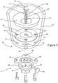
Figure 3 is a cross-sectional exploded view of the attachment lock connected to a socket; and -
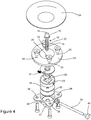
Figure 4 is an exploded view of the attachment lock. - Referring initially to
Figure 1 there is shown aprosthetic liner 10 connected to theresidual limb 11 of a patient (not shown). Theliner 10 has a reinforceddistal end 12 configured for connection of aprosthetic locking pin 13. The lockingpin 13 is a rastered locking pin having aconnecter 14, which is screwed into a threaded bush in theliner 10 and adhered thereto for added security. Ashoulder 15 separates theconnector 14 from sloped (saw-tooth)serrations 18 along the length of the shaft. Eachserration 18 is defined by asloped part 19 and aflat edge 20. -
Figures 1 and 2 show a trans-femoral prosthetic socket 21 which is formed from a rigid material and is custom-made to correspond to the shape and configuration of the patientsresidual limb 11. Thesocket 21 has anopening 22 formed in thedistal end 23 for receiving the lockingpin 13. Mountingholes 24 are also formed through thedistal end 23 of thesocket 21. Anannular clamping plate 25 having anopening 26 formed therethrough is located within the socket and hasholes 33 in registration with the mounting holes 24. Aflexible sealing ring 34 is positioned above the clamping plate. The sealing ring is formed from a foam-like material and is arranged to conform to the shape of theliner 10 so as to provide support to theresidual limb 11. - Referring now to all of the Figures, an
attachment lock 27 connects thesocket 21 to theliner 10 and comprises ahousing 28 in which a lockingmember 29 is contained. The lockingmember 29 contains a ratchet-type lock having apawl member 30 connected to aspring 31 and configured to engage theserrations 18 of the lockingpin 13. An opening 32 is formed in theattachment lock 27, which allows the lockingpin 13 of aliner 10 to be inserted into the attachment lock and to engage with thepawl member 30 of the lockingmember 29. A release member is provided to disengage thepawl member 30 from theserrations 18 of the lockingpin 13 and this comprises arod 39 releasably connected to thepawl member 30 and having a manuallyoperable button 40 at one end. - The
attachment lock 27 includes means to adjust the position of the locking member relative to the housing along the axis of an inserted locking pin and in the figures the means comprises twospacers 35. Thespacers 35 are positioned between the lockingmember 29 and thehousing 28 in order to reduce the amount of free play between thepawl 30 and the twoadjacent serrations 18. This serves to prevent the occurrence of pistoning and undesirable noise. In this arrangement the spacers have openings 36 in registration with the opening 32 formed in theattachment lock 27 and are provided below the lockingmember 29 so as to raise themember 29 relative to thehousing 28. - A pyramid-shaped
adaptor 37 is provided at the distal end of thehousing 28 and is used to connect a prosthetic limb (not shown) to theattachment lock 27. Thehousing 28 includes mountingholes 38 for mounting theattachment lock 27 to thesocket 21. In a preferred arrangement, the mountingholes 24 in thesocket 21 are not pre-formed but are drilled during fitting of thesocket 21 so that the orientation of theattachment lock 27 relative to the socket can be tailored specifically to the patient.
Claims (9)
- An attachment lock (27) for a prosthetic limb comprising:- a housing (28) having an opening (32) for insertion of a prosthetic locking pin (13);- a locking member (29) mounted within the housing (28) and arranged releasably to secure an inserted locking pin (13); and- a release member operatively connected to the locking member (29) and operable to release the locking member (29) from an inserted locking pin (13),characterized in that the attachment lock (27) comprises means to adjust the position of the locking member (29) relative to the housing (28) along the axis of an inserted locking pin (13) to adjust the position at which an inserted locking pin (13) may be held.
- An attachment lock as claimed in claim 1, wherein the housing (28) includes a mounting member configured releasably to mount the attachment lock (27) to a prosthetic socket (21).
- An attachment lock as claimed in claim 2, wherein at least two holes (38) are formed through the mounting member, each hole (38) being configured for attaching the mounting member to a prosthetic socket (21).
- An attachment lock as claimed in any of claims 1 to 3, wherein the means to adjust the position of the locking member (29) comprises a spacer (35) of a selected thickness positioned between the locking member (29) and the housing (28).
- An attachment lock as claimed in claim 4, comprising a plurality of spacers (35).
- An attachment lock as claimed in claim 4 or claim 5, wherein the spacer (35) has a hole (36) in register with the opening (32).
- An attachment lock as claimed in any of the preceding claims, wherein the release member comprises a rod (39) releasably connected to the locking member (29).
- An attachment lock as claimed in claim 7, wherein the rod (39) is screw threaded and engages with the locking member (29).
- An attachment lock as claimed in any of the preceding claims, wherein the locking member (29) contains a ratchet-type lock.
Applications Claiming Priority (2)
| Application Number | Priority Date | Filing Date | Title |
|---|---|---|---|
| GBGB1303341.0A GB201303341D0 (en) | 2013-02-26 | 2013-02-26 | Prosthetic attachment lock |
| PCT/GB2014/050339 WO2014132029A2 (en) | 2013-02-26 | 2014-02-06 | Prosthetic attachment lock |
Publications (2)
| Publication Number | Publication Date |
|---|---|
| EP2961357A2 EP2961357A2 (en) | 2016-01-06 |
| EP2961357B1 true EP2961357B1 (en) | 2019-07-24 |
Family
ID=48092069
Family Applications (1)
| Application Number | Title | Priority Date | Filing Date |
|---|---|---|---|
| EP14712019.0A Active EP2961357B1 (en) | 2013-02-26 | 2014-02-06 | Prosthetic attachment lock |
Country Status (6)
| Country | Link |
|---|---|
| US (1) | US10206794B2 (en) |
| EP (1) | EP2961357B1 (en) |
| CN (1) | CN105025847A (en) |
| GB (1) | GB201303341D0 (en) |
| HK (1) | HK1216837A1 (en) |
| WO (1) | WO2014132029A2 (en) |
Families Citing this family (13)
| Publication number | Priority date | Publication date | Assignee | Title |
|---|---|---|---|---|
| US10842653B2 (en) | 2007-09-19 | 2020-11-24 | Ability Dynamics, Llc | Vacuum system for a prosthetic foot |
| SE539252C2 (en) * | 2015-12-11 | 2017-05-30 | Integrum Ab | Attachment device allowing natural wrist rotation for osseointegrated prostheses |
| US20170333225A1 (en) * | 2016-05-18 | 2017-11-23 | Ken Dall Enterprise Co., Ltd. | Prosthesis carring barrel suction-attaching joint with locking function |
| WO2018217618A2 (en) | 2017-05-22 | 2018-11-29 | Ossur Iceland Ehf | Prosthetic attachment system |
| CN107411856A (en) * | 2017-05-25 | 2017-12-01 | 国家康复辅具研究中心 | Artificial limb and aid |
| CN109106482A (en) * | 2017-06-26 | 2019-01-01 | 肯达路企业股份有限公司 | Artificial limb socket vacuum device |
| CN108742958A (en) * | 2018-04-03 | 2018-11-06 | 西安交通大学 | A kind of adaptive prosthetic socket of flexibility |
| EP3908232B1 (en) | 2019-01-10 | 2024-01-03 | Össur Iceland EHF | Prosthetic attachment system and corresponding lock assembly |
| CN111012553B (en) * | 2019-12-19 | 2024-08-13 | 中国人民解放军第二军医大学第二附属医院 | Height-adjustable artificial vertebra |
| EP4208130B1 (en) | 2020-09-04 | 2026-01-28 | Ossur Iceland Ehf | Interchangeable distal end for a prosthetic socket system |
| CN112245076B (en) * | 2020-11-05 | 2023-08-18 | 北京星辰之翼科技有限公司 | A connection structure between the connecting rod of the silicone sleeve of the residual limb and the connecting part of the prosthesis |
| CN113693795B (en) * | 2021-08-30 | 2023-06-09 | 北京积水潭医院 | Prosthetic limb disengaging device |
| WO2023166602A1 (en) * | 2022-03-02 | 2023-09-07 | インスタリム株式会社 | Prosthetic socket, prosthesis system, and prosthesis |
Family Cites Families (88)
| Publication number | Priority date | Publication date | Assignee | Title |
|---|---|---|---|---|
| US980457A (en) | 1910-01-13 | 1911-01-03 | Justin Kay Toles | Artificial limb. |
| US1398824A (en) | 1921-03-01 | 1921-11-29 | Abrams Joseph | Artificial-limb socket |
| GB267988A (en) | 1925-09-18 | 1927-03-18 | Charles Albert Blatchford | Improvements in or connected with artificial limbs |
| US1893853A (en) | 1931-12-15 | 1933-01-10 | Amos E Tullis | Artificial limb |
| DE745981C (en) | 1940-09-21 | 1944-05-22 | Alois Geisen | Artificial leg with a sleeve to be attached to the leg stump by suction |
| US2530285A (en) | 1947-12-11 | 1950-11-14 | John G Catranis | Artificial leg |
| US2533404A (en) | 1948-08-13 | 1950-12-12 | Sharp Oscar | Artificial limb and valve therefor |
| DE813190C (en) | 1948-10-02 | 1951-09-10 | Franz Clouth | Suction prosthesis |
| BE505683A (en) | 1950-09-19 | |||
| US2671225A (en) | 1951-11-05 | 1954-03-09 | Bardach Schoene Company Inc | Artificial limb stump socket |
| US2808593A (en) | 1956-02-07 | 1957-10-08 | Andersen Algot | Artificial limbs |
| DE1795809U (en) | 1958-08-23 | 1959-09-17 | Hildegard Seitz | ORTHOPEDIC LEG OR ARM PROTHESIS. |
| US3393407A (en) | 1965-12-16 | 1968-07-23 | Edward J. Kandel | Artificial limb with end-bearing socket and method of making |
| DE2060239C3 (en) | 1970-12-08 | 1974-05-09 | Surerus, Walter, Dr.Med., 7016 Gerlingen | Prosthesis socket with a ring-shaped support insert, especially for leg prostheses |
| US3671980A (en) | 1971-02-19 | 1972-06-27 | Lincoln F Baird | Fluid pressure clamp for prosthetic appliance |
| DE2540138C3 (en) | 1975-09-09 | 1978-03-02 | Walter Dr.Med. 7016 Gerlingen Surerus | Annular support insert for a prosthesis socket |
| DE2729800A1 (en) | 1977-07-01 | 1979-01-04 | Walter Dr Med Surerus | Knee joint prosthesis pressure chamber for stump - incorporates pneumatic ring and double valve system including pump connection |
| GB2069847B (en) | 1980-02-22 | 1985-01-23 | Blatchford & Sons Ltd | Artificial limb |
| GB2087727B (en) | 1980-10-14 | 1984-01-25 | Steeper Hugh Ltd | Manufacture of a prosthetics socket |
| DE3221920A1 (en) | 1982-06-11 | 1983-04-07 | Surerus, Walter, Dr., 7016 Gerlingen | Prosthesis stem |
| US4564365A (en) | 1983-03-18 | 1986-01-14 | Winer Richard A | Quick change mechanism for a limb prosthesis |
| DE3508919A1 (en) | 1985-03-13 | 1986-09-18 | Surerus, Walter, Dr.Med., 7016 Gerlingen | Prosthetic shaft |
| SE454943B (en) | 1986-06-26 | 1988-06-13 | Ossur Hf | ACCESSORIES, SPECIAL FOR AMPUTATION STUMP |
| US5007937A (en) | 1988-03-31 | 1991-04-16 | New York University Medical Center | Structure for enhanced retention of artificial limbs and method of fabrication |
| US4938775A (en) * | 1989-04-03 | 1990-07-03 | Morgan Robert D | Artificial leg with bearings for rotational motion |
| US5376129A (en) | 1990-12-04 | 1994-12-27 | Board Of Regents, The University Of Texas System | Method and apparatus for making prosthetic socket preforms, prosthetic sockets, and socket attachment component |
| US5139523A (en) | 1991-07-12 | 1992-08-18 | Paton Matthew T | Artificial limb socket apparatus |
| US5163965A (en) | 1991-07-29 | 1992-11-17 | Becker Orthopedic Appliance Company | Prosthetic attachment device and method |
| US5226918A (en) | 1992-07-13 | 1993-07-13 | Howard Silagy | Prosthesis with adjustable fitting clearance |
| US5314496A (en) | 1992-12-31 | 1994-05-24 | Harris Bertram H | Stump sock arrangement |
| US5413392A (en) * | 1993-04-06 | 1995-05-09 | Southco, Inc. | Pawl assembly |
| US5376131A (en) | 1993-07-01 | 1994-12-27 | Manhasset Orthotics And Prosthetics, Ltd. | Suction socket for artificial limb |
| JPH0822295B2 (en) | 1993-12-03 | 1996-03-06 | 株式会社奈良義肢 | Mounting structure for artificial legs or hands |
| US5507837A (en) * | 1994-09-21 | 1996-04-16 | Laghi; Aldo A. | Prosthetic locking device with integral pyramid |
| DE9419208U1 (en) | 1994-11-30 | 1995-01-26 | Carstens, Felix, 67433 Neustadt | Artificial link |
| US5728167A (en) | 1995-01-11 | 1998-03-17 | Lohmann; Klaus H. | Prosthetic sock for reducing movement between residual limb and prosthesis |
| US5593454A (en) | 1995-01-12 | 1997-01-14 | Helmy; Nashat N. | Artificial limb mounting apparatus |
| US5662715A (en) | 1995-07-19 | 1997-09-02 | Materials Engineering And Development, Inc. | Modular interface connector for a prosthetic limb |
| US5549709A (en) | 1995-07-26 | 1996-08-27 | Caspers; Carl A. | Hypobarically-Controlled artificial limb for amputees |
| US5735906A (en) | 1995-07-26 | 1998-04-07 | Caspers; Carl A. | Hypobarically-controlled artificial limb with detents for amputees |
| US5702489A (en) | 1995-08-18 | 1997-12-30 | Materials Engineering And Development, Inc. | Valve assembly for a prosthetic limb |
| US6287345B1 (en) | 1995-08-18 | 2001-09-11 | The Ohio Willow Wood Company | Valve assembly for a prosthetic limb |
| ES2152353T3 (en) | 1995-09-08 | 2001-02-01 | Bock Orthopaed Ind | LEG PROTESIS |
| US5658353A (en) | 1995-10-31 | 1997-08-19 | Layton; Harry W. | Method for donning or doffing an artificial limb |
| US5718925A (en) * | 1995-11-15 | 1998-02-17 | Ossur Hf. | Apparatus for making a prosthesis socket |
| US5888216A (en) | 1996-03-18 | 1999-03-30 | Haberman; Louis J. | Prosthesis liner for below-knee amputees |
| US5882053A (en) * | 1996-06-14 | 1999-03-16 | Donnelly Corporation | Vehicle door/tailgate assembly with centering feature |
| US6063125A (en) | 1997-02-14 | 2000-05-16 | Ohio Willow Wood Company | Suspension/alignment for prosthetic limbs |
| US5888230A (en) | 1997-04-01 | 1999-03-30 | Helmy; Nashat N. | Modular liner for limb stump prosthesis |
| SE511603C2 (en) | 1997-11-27 | 1999-10-25 | Finn Gramnaes | Locking device intended as a fastener for a prosthesis |
| WO1999035422A1 (en) | 1998-01-09 | 1999-07-15 | Swagelok Company | Seal for a modular flow devices |
| US6149691A (en) | 1998-06-26 | 2000-11-21 | Fay; John N. | Self-inflating socket having encased gel |
| GB2338899A (en) | 1998-07-01 | 2000-01-12 | Ortho Europ Limited | Connector for orthoses or prostheses |
| US6361568B1 (en) | 1999-02-09 | 2002-03-26 | Alps South Corporation | Prosthetic sleeve with air outlet valve |
| US6106559A (en) * | 1999-03-25 | 2000-08-22 | Meyer; Dennis E. | Socket coupler for a prosthetic limb |
| US6440173B1 (en) | 1999-03-25 | 2002-08-27 | Dennis E. Meyer | Socket coupler for a prosthetic limb |
| US6258065B1 (en) | 1999-03-26 | 2001-07-10 | Core Dynamics, Inc. | Surgical instrument seal assembly |
| US6554868B1 (en) | 1999-06-03 | 2003-04-29 | Carl A. Caspers | Vacuum pump and shock absorber for artificial limb |
| US6645253B2 (en) | 1999-06-03 | 2003-11-11 | Carl A. Caspers | Vacuum pump and shock absorber for artificial limb |
| US6926742B2 (en) | 1999-06-03 | 2005-08-09 | Otto Bock Healthcare Lp | Plate/socket attachment for artificial limb vacuum pump |
| WO2000074611A2 (en) | 1999-06-03 | 2000-12-14 | Caspers-Schneider Technologies,Inc. | Hypobarically-controlled socket for artificial limb |
| US7922775B2 (en) | 1999-06-03 | 2011-04-12 | Otto Bock Healthcare Lp | Pulsating pressure chamber and method for fluid management |
| US6726726B2 (en) | 1999-06-03 | 2004-04-27 | Otto Bock Healthcare Lp | Vacuum apparatus and method for managing residual limb volume in an artificial limb |
| US20010016781A1 (en) | 1999-06-03 | 2001-08-23 | Caspers Carl A. | Osmotic membrane and vacuum system for artificial limb |
| US6508842B1 (en) | 1999-06-03 | 2003-01-21 | Barbara J. Caspers | Socket liner for artificial limb |
| US20040098136A1 (en) | 1999-06-03 | 2004-05-20 | Caspers Carl A. | Socket liner for artificial limb with permanent attachment to socket |
| US6231617B1 (en) | 1999-07-14 | 2001-05-15 | John N. Fay | Prosthetic liner having longitudinal inelasticity |
| US6273918B1 (en) | 1999-08-26 | 2001-08-14 | Jason R. Yuhasz | Magnetic detachment system for prosthetics |
| US6585774B2 (en) | 2000-04-25 | 2003-07-01 | Simbex, Llc | Dynamic variable geometry fitting system for use with a body appliance |
| US7234108B1 (en) | 2000-06-29 | 2007-06-19 | Microsoft Corporation | Ink thickness rendering for electronic annotations |
| AU2002211218A1 (en) | 2000-10-04 | 2002-04-15 | Ossur Hf | Prosthetic socket and socket component assembly |
| DE10142492A1 (en) | 2001-08-30 | 2003-04-03 | Carstens Orthopaedie Und Mediz | Prosthetic socket with seal |
| DE10142491B4 (en) | 2001-08-30 | 2004-10-07 | össur h.f. | Sealing arrangement with lips for a prosthetic socket |
| DE10164892B4 (en) * | 2001-11-05 | 2009-08-27 | össur h.f. | Stocking liner for use with a cup-shaped prosthesis stem |
| US20030195636A1 (en) | 2002-04-12 | 2003-10-16 | Coop Brian T. | Prosthetic locking device |
| AU2003233682A1 (en) | 2002-05-23 | 2003-12-12 | Otto Bock Healthcare Lp | Pulsating pressure chamber and method for enhanced blood flow |
| CA2501488C (en) | 2002-11-01 | 2013-02-26 | Otto Bock Healthcare Lp | Pressure/temperature monitoring device for prosthetics |
| US7025793B2 (en) | 2002-12-20 | 2006-04-11 | Ossur Hf | Suspension liner with seal |
| US7351367B2 (en) | 2003-04-11 | 2008-04-01 | Bionix Prosthetic Solutions, Inc. | Adapter bracket for prostheses, method and apparatus for forming prosthetic device with transfer of proper alignment |
| EP1653893A4 (en) | 2003-06-20 | 2009-11-11 | Ossur Hf | Prosthetic socket with self-contained vacuum reservoir |
| US7217060B2 (en) * | 2004-04-30 | 2007-05-15 | Ossur Hf | Prosthesis locking assembly |
| DE102004043805B3 (en) * | 2004-09-08 | 2006-03-30 | Otto Bock Healthcare Ip Gmbh & Co. Kg | Clamp freewheel and use for a prosthetic part |
| US7771487B2 (en) | 2005-08-01 | 2010-08-10 | Mantelmacher H Lee | Anti-slip attachment and drainage system for prosthetics |
| WO2007030609A2 (en) * | 2005-09-08 | 2007-03-15 | Charles King | Vacuum assisted heat/perspiration removal system and limb volume management for prosthetic device |
| US8211187B2 (en) | 2008-06-09 | 2012-07-03 | Prosthetic Design, Inc. | Elevated vacuum locking system |
| US20120310371A1 (en) | 2010-01-29 | 2012-12-06 | The University Of Utah Research Foundation (Uurf) | Releasable attachment system for a prosthetic limb |
| GB2479532A (en) | 2010-04-12 | 2011-10-19 | Stanmore Implants Worldwide Ltd | Fail-safe attachment for prosthetic limb |
| US8562692B2 (en) * | 2010-05-10 | 2013-10-22 | Coyote Design And Manufacturing, Inc. | Distal lock for a prosthetic hard socket |
-
2013
- 2013-02-26 GB GBGB1303341.0A patent/GB201303341D0/en not_active Ceased
-
2014
- 2014-02-06 EP EP14712019.0A patent/EP2961357B1/en active Active
- 2014-02-06 HK HK16104705.0A patent/HK1216837A1/en unknown
- 2014-02-06 US US14/770,273 patent/US10206794B2/en active Active
- 2014-02-06 CN CN201480010447.5A patent/CN105025847A/en active Pending
- 2014-02-06 WO PCT/GB2014/050339 patent/WO2014132029A2/en not_active Ceased
Non-Patent Citations (1)
| Title |
|---|
| None * |
Also Published As
| Publication number | Publication date |
|---|---|
| EP2961357A2 (en) | 2016-01-06 |
| CN105025847A (en) | 2015-11-04 |
| US20160000584A1 (en) | 2016-01-07 |
| WO2014132029A3 (en) | 2014-10-23 |
| GB201303341D0 (en) | 2013-04-10 |
| US10206794B2 (en) | 2019-02-19 |
| WO2014132029A2 (en) | 2014-09-04 |
| HK1216837A1 (en) | 2016-12-09 |
Similar Documents
| Publication | Publication Date | Title |
|---|---|---|
| US10206794B2 (en) | Prosthetic attachment lock | |
| US6596027B2 (en) | Rachet type prosthetic lock | |
| AU2003304241B2 (en) | Shroud plate | |
| CA2498127C (en) | Shroud plate attachment | |
| US7217060B2 (en) | Prosthesis locking assembly | |
| EP1722264A1 (en) | Impact resistant eyewear frame assembly having a split frame and fastener reinforcement | |
| US20020116071A1 (en) | Shuttle lock | |
| EP2514393A1 (en) | Hinge brace assembly having a structural outer plate | |
| US8562692B2 (en) | Distal lock for a prosthetic hard socket | |
| CN103930070B (en) | With the rotary joint prosthese of the splicing sleeve of strengthening | |
| US8808393B2 (en) | Leg prosthesis | |
| US6589288B2 (en) | Adjustable plunger pin assembly for a prosthetic limb | |
| US20240307193A1 (en) | Implant extractor | |
| JP5602736B2 (en) | Endoprosthesis with plug-in coupling and improved anti-rotation | |
| WO2009061306A1 (en) | Dental implant screw system | |
| PT2285316E (en) | Limb stump receiving sleeve comprising an integrated locking device for a sealing element | |
| KR102339789B1 (en) | Detachable implant binding prosthesis with easy detachement | |
| CA2507720A1 (en) | Rotation-proof enclosure for pressure switch housing | |
| EP4387572B1 (en) | Prosthetic attachment system and corresponding lock assembly | |
| WO2006103430A1 (en) | Prosthetic alignment device | |
| US20250387242A1 (en) | Method and Apparatus for a Prosthetic Device and a Prosthetic Coupling Device | |
| WO2024177977A1 (en) | Method and apparatus for a prosthetic device | |
| TWI292697B (en) | ||
| DE202019100815U1 (en) | hearing | |
| WO2022005295A1 (en) | Adaptor for mounting a prosthesis |
Legal Events
| Date | Code | Title | Description |
|---|---|---|---|
| PUAI | Public reference made under article 153(3) epc to a published international application that has entered the european phase |
Free format text: ORIGINAL CODE: 0009012 |
|
| 17P | Request for examination filed |
Effective date: 20150828 |
|
| AK | Designated contracting states |
Kind code of ref document: A2 Designated state(s): AL AT BE BG CH CY CZ DE DK EE ES FI FR GB GR HR HU IE IS IT LI LT LU LV MC MK MT NL NO PL PT RO RS SE SI SK SM TR |
|
| AX | Request for extension of the european patent |
Extension state: BA ME |
|
| DAX | Request for extension of the european patent (deleted) | ||
| RAP1 | Party data changed (applicant data changed or rights of an application transferred) |
Owner name: MEDI PROSTHETICS GMBH |
|
| RIN1 | Information on inventor provided before grant (corrected) |
Inventor name: MEDI PROSTHETICS GMBH |
|
| RAP1 | Party data changed (applicant data changed or rights of an application transferred) |
Owner name: OESSUR ICELAND EHF |
|
| RIN1 | Information on inventor provided before grant (corrected) |
Inventor name: OESSUR ICELAND EHF |
|
| STAA | Information on the status of an ep patent application or granted ep patent |
Free format text: STATUS: EXAMINATION IS IN PROGRESS |
|
| 17Q | First examination report despatched |
Effective date: 20180611 |
|
| GRAP | Despatch of communication of intention to grant a patent |
Free format text: ORIGINAL CODE: EPIDOSNIGR1 |
|
| STAA | Information on the status of an ep patent application or granted ep patent |
Free format text: STATUS: GRANT OF PATENT IS INTENDED |
|
| INTG | Intention to grant announced |
Effective date: 20190208 |
|
| RIN1 | Information on inventor provided before grant (corrected) |
Inventor name: BROWN, GEOFFREY |
|
| GRAS | Grant fee paid |
Free format text: ORIGINAL CODE: EPIDOSNIGR3 |
|
| GRAA | (expected) grant |
Free format text: ORIGINAL CODE: 0009210 |
|
| STAA | Information on the status of an ep patent application or granted ep patent |
Free format text: STATUS: THE PATENT HAS BEEN GRANTED |
|
| AK | Designated contracting states |
Kind code of ref document: B1 Designated state(s): AL AT BE BG CH CY CZ DE DK EE ES FI FR GB GR HR HU IE IS IT LI LT LU LV MC MK MT NL NO PL PT RO RS SE SI SK SM TR |
|
| REG | Reference to a national code |
Ref country code: GB Ref legal event code: FG4D |
|
| REG | Reference to a national code |
Ref country code: CH Ref legal event code: EP |
|
| REG | Reference to a national code |
Ref country code: DE Ref legal event code: R096 Ref document number: 602014050414 Country of ref document: DE |
|
| REG | Reference to a national code |
Ref country code: AT Ref legal event code: REF Ref document number: 1157305 Country of ref document: AT Kind code of ref document: T Effective date: 20190815 |
|
| REG | Reference to a national code |
Ref country code: IE Ref legal event code: FG4D |
|
| REG | Reference to a national code |
Ref country code: NL Ref legal event code: MP Effective date: 20190724 |
|
| REG | Reference to a national code |
Ref country code: LT Ref legal event code: MG4D |
|
| REG | Reference to a national code |
Ref country code: AT Ref legal event code: MK05 Ref document number: 1157305 Country of ref document: AT Kind code of ref document: T Effective date: 20190724 |
|
| PG25 | Lapsed in a contracting state [announced via postgrant information from national office to epo] |
Ref country code: NO Free format text: LAPSE BECAUSE OF FAILURE TO SUBMIT A TRANSLATION OF THE DESCRIPTION OR TO PAY THE FEE WITHIN THE PRESCRIBED TIME-LIMIT Effective date: 20191024 Ref country code: AT Free format text: LAPSE BECAUSE OF FAILURE TO SUBMIT A TRANSLATION OF THE DESCRIPTION OR TO PAY THE FEE WITHIN THE PRESCRIBED TIME-LIMIT Effective date: 20190724 Ref country code: SE Free format text: LAPSE BECAUSE OF FAILURE TO SUBMIT A TRANSLATION OF THE DESCRIPTION OR TO PAY THE FEE WITHIN THE PRESCRIBED TIME-LIMIT Effective date: 20190724 Ref country code: FI Free format text: LAPSE BECAUSE OF FAILURE TO SUBMIT A TRANSLATION OF THE DESCRIPTION OR TO PAY THE FEE WITHIN THE PRESCRIBED TIME-LIMIT Effective date: 20190724 Ref country code: HR Free format text: LAPSE BECAUSE OF FAILURE TO SUBMIT A TRANSLATION OF THE DESCRIPTION OR TO PAY THE FEE WITHIN THE PRESCRIBED TIME-LIMIT Effective date: 20190724 Ref country code: PT Free format text: LAPSE BECAUSE OF FAILURE TO SUBMIT A TRANSLATION OF THE DESCRIPTION OR TO PAY THE FEE WITHIN THE PRESCRIBED TIME-LIMIT Effective date: 20191125 Ref country code: BG Free format text: LAPSE BECAUSE OF FAILURE TO SUBMIT A TRANSLATION OF THE DESCRIPTION OR TO PAY THE FEE WITHIN THE PRESCRIBED TIME-LIMIT Effective date: 20191024 Ref country code: NL Free format text: LAPSE BECAUSE OF FAILURE TO SUBMIT A TRANSLATION OF THE DESCRIPTION OR TO PAY THE FEE WITHIN THE PRESCRIBED TIME-LIMIT Effective date: 20190724 Ref country code: LT Free format text: LAPSE BECAUSE OF FAILURE TO SUBMIT A TRANSLATION OF THE DESCRIPTION OR TO PAY THE FEE WITHIN THE PRESCRIBED TIME-LIMIT Effective date: 20190724 |
|
| PG25 | Lapsed in a contracting state [announced via postgrant information from national office to epo] |
Ref country code: AL Free format text: LAPSE BECAUSE OF FAILURE TO SUBMIT A TRANSLATION OF THE DESCRIPTION OR TO PAY THE FEE WITHIN THE PRESCRIBED TIME-LIMIT Effective date: 20190724 Ref country code: ES Free format text: LAPSE BECAUSE OF FAILURE TO SUBMIT A TRANSLATION OF THE DESCRIPTION OR TO PAY THE FEE WITHIN THE PRESCRIBED TIME-LIMIT Effective date: 20190724 Ref country code: GR Free format text: LAPSE BECAUSE OF FAILURE TO SUBMIT A TRANSLATION OF THE DESCRIPTION OR TO PAY THE FEE WITHIN THE PRESCRIBED TIME-LIMIT Effective date: 20191025 Ref country code: LV Free format text: LAPSE BECAUSE OF FAILURE TO SUBMIT A TRANSLATION OF THE DESCRIPTION OR TO PAY THE FEE WITHIN THE PRESCRIBED TIME-LIMIT Effective date: 20190724 Ref country code: RS Free format text: LAPSE BECAUSE OF FAILURE TO SUBMIT A TRANSLATION OF THE DESCRIPTION OR TO PAY THE FEE WITHIN THE PRESCRIBED TIME-LIMIT Effective date: 20190724 Ref country code: IS Free format text: LAPSE BECAUSE OF FAILURE TO SUBMIT A TRANSLATION OF THE DESCRIPTION OR TO PAY THE FEE WITHIN THE PRESCRIBED TIME-LIMIT Effective date: 20191124 |
|
| PG25 | Lapsed in a contracting state [announced via postgrant information from national office to epo] |
Ref country code: TR Free format text: LAPSE BECAUSE OF FAILURE TO SUBMIT A TRANSLATION OF THE DESCRIPTION OR TO PAY THE FEE WITHIN THE PRESCRIBED TIME-LIMIT Effective date: 20190724 |
|
| PG25 | Lapsed in a contracting state [announced via postgrant information from national office to epo] |
Ref country code: RO Free format text: LAPSE BECAUSE OF FAILURE TO SUBMIT A TRANSLATION OF THE DESCRIPTION OR TO PAY THE FEE WITHIN THE PRESCRIBED TIME-LIMIT Effective date: 20190724 Ref country code: PL Free format text: LAPSE BECAUSE OF FAILURE TO SUBMIT A TRANSLATION OF THE DESCRIPTION OR TO PAY THE FEE WITHIN THE PRESCRIBED TIME-LIMIT Effective date: 20190724 Ref country code: EE Free format text: LAPSE BECAUSE OF FAILURE TO SUBMIT A TRANSLATION OF THE DESCRIPTION OR TO PAY THE FEE WITHIN THE PRESCRIBED TIME-LIMIT Effective date: 20190724 Ref country code: DK Free format text: LAPSE BECAUSE OF FAILURE TO SUBMIT A TRANSLATION OF THE DESCRIPTION OR TO PAY THE FEE WITHIN THE PRESCRIBED TIME-LIMIT Effective date: 20190724 Ref country code: IT Free format text: LAPSE BECAUSE OF FAILURE TO SUBMIT A TRANSLATION OF THE DESCRIPTION OR TO PAY THE FEE WITHIN THE PRESCRIBED TIME-LIMIT Effective date: 20190724 |
|
| PG25 | Lapsed in a contracting state [announced via postgrant information from national office to epo] |
Ref country code: CZ Free format text: LAPSE BECAUSE OF FAILURE TO SUBMIT A TRANSLATION OF THE DESCRIPTION OR TO PAY THE FEE WITHIN THE PRESCRIBED TIME-LIMIT Effective date: 20190724 Ref country code: SM Free format text: LAPSE BECAUSE OF FAILURE TO SUBMIT A TRANSLATION OF THE DESCRIPTION OR TO PAY THE FEE WITHIN THE PRESCRIBED TIME-LIMIT Effective date: 20190724 Ref country code: IS Free format text: LAPSE BECAUSE OF FAILURE TO SUBMIT A TRANSLATION OF THE DESCRIPTION OR TO PAY THE FEE WITHIN THE PRESCRIBED TIME-LIMIT Effective date: 20200224 Ref country code: SK Free format text: LAPSE BECAUSE OF FAILURE TO SUBMIT A TRANSLATION OF THE DESCRIPTION OR TO PAY THE FEE WITHIN THE PRESCRIBED TIME-LIMIT Effective date: 20190724 |
|
| REG | Reference to a national code |
Ref country code: DE Ref legal event code: R097 Ref document number: 602014050414 Country of ref document: DE |
|
| PLBE | No opposition filed within time limit |
Free format text: ORIGINAL CODE: 0009261 |
|
| STAA | Information on the status of an ep patent application or granted ep patent |
Free format text: STATUS: NO OPPOSITION FILED WITHIN TIME LIMIT |
|
| PG2D | Information on lapse in contracting state deleted |
Ref country code: IS |
|
| 26N | No opposition filed |
Effective date: 20200603 |
|
| PG25 | Lapsed in a contracting state [announced via postgrant information from national office to epo] |
Ref country code: SI Free format text: LAPSE BECAUSE OF FAILURE TO SUBMIT A TRANSLATION OF THE DESCRIPTION OR TO PAY THE FEE WITHIN THE PRESCRIBED TIME-LIMIT Effective date: 20190724 |
|
| REG | Reference to a national code |
Ref country code: CH Ref legal event code: PL |
|
| REG | Reference to a national code |
Ref country code: BE Ref legal event code: MM Effective date: 20200229 |
|
| PG25 | Lapsed in a contracting state [announced via postgrant information from national office to epo] |
Ref country code: LU Free format text: LAPSE BECAUSE OF NON-PAYMENT OF DUE FEES Effective date: 20200206 Ref country code: MC Free format text: LAPSE BECAUSE OF FAILURE TO SUBMIT A TRANSLATION OF THE DESCRIPTION OR TO PAY THE FEE WITHIN THE PRESCRIBED TIME-LIMIT Effective date: 20190724 |
|
| PG25 | Lapsed in a contracting state [announced via postgrant information from national office to epo] |
Ref country code: CH Free format text: LAPSE BECAUSE OF NON-PAYMENT OF DUE FEES Effective date: 20200229 Ref country code: LI Free format text: LAPSE BECAUSE OF NON-PAYMENT OF DUE FEES Effective date: 20200229 |
|
| PG25 | Lapsed in a contracting state [announced via postgrant information from national office to epo] |
Ref country code: FR Free format text: LAPSE BECAUSE OF NON-PAYMENT OF DUE FEES Effective date: 20200229 Ref country code: IE Free format text: LAPSE BECAUSE OF NON-PAYMENT OF DUE FEES Effective date: 20200206 |
|
| PG25 | Lapsed in a contracting state [announced via postgrant information from national office to epo] |
Ref country code: BE Free format text: LAPSE BECAUSE OF NON-PAYMENT OF DUE FEES Effective date: 20200229 |
|
| PG25 | Lapsed in a contracting state [announced via postgrant information from national office to epo] |
Ref country code: MT Free format text: LAPSE BECAUSE OF FAILURE TO SUBMIT A TRANSLATION OF THE DESCRIPTION OR TO PAY THE FEE WITHIN THE PRESCRIBED TIME-LIMIT Effective date: 20190724 Ref country code: CY Free format text: LAPSE BECAUSE OF FAILURE TO SUBMIT A TRANSLATION OF THE DESCRIPTION OR TO PAY THE FEE WITHIN THE PRESCRIBED TIME-LIMIT Effective date: 20190724 |
|
| PG25 | Lapsed in a contracting state [announced via postgrant information from national office to epo] |
Ref country code: MK Free format text: LAPSE BECAUSE OF FAILURE TO SUBMIT A TRANSLATION OF THE DESCRIPTION OR TO PAY THE FEE WITHIN THE PRESCRIBED TIME-LIMIT Effective date: 20190724 |
|
| P01 | Opt-out of the competence of the unified patent court (upc) registered |
Effective date: 20230518 |
|
| PGFP | Annual fee paid to national office [announced via postgrant information from national office to epo] |
Ref country code: GB Payment date: 20260217 Year of fee payment: 13 |
|
| PGFP | Annual fee paid to national office [announced via postgrant information from national office to epo] |
Ref country code: DE Payment date: 20260217 Year of fee payment: 13 |