EP2961329B1 - Device providing enlargement and preventing collapse of the pupil of the eye - Google Patents
Device providing enlargement and preventing collapse of the pupil of the eye Download PDFInfo
- Publication number
- EP2961329B1 EP2961329B1 EP13771217.0A EP13771217A EP2961329B1 EP 2961329 B1 EP2961329 B1 EP 2961329B1 EP 13771217 A EP13771217 A EP 13771217A EP 2961329 B1 EP2961329 B1 EP 2961329B1
- Authority
- EP
- European Patent Office
- Prior art keywords
- ring
- notches
- corners
- notch
- flanges
- Prior art date
- Legal status (The legal status is an assumption and is not a legal conclusion. Google has not performed a legal analysis and makes no representation as to the accuracy of the status listed.)
- Active
Links
- 210000001747 pupil Anatomy 0.000 title claims description 25
- 230000001179 pupillary effect Effects 0.000 claims description 45
- 230000001154 acute effect Effects 0.000 claims description 4
- 238000000034 method Methods 0.000 claims description 4
- 239000000463 material Substances 0.000 claims description 3
- 230000002265 prevention Effects 0.000 claims description 3
- 240000007817 Olea europaea Species 0.000 claims description 2
- 238000001356 surgical procedure Methods 0.000 description 11
- 238000003780 insertion Methods 0.000 description 8
- 230000037431 insertion Effects 0.000 description 8
- 101100126625 Caenorhabditis elegans itr-1 gene Proteins 0.000 description 3
- 239000000853 adhesive Substances 0.000 description 3
- 230000001070 adhesive effect Effects 0.000 description 3
- 210000002159 anterior chamber Anatomy 0.000 description 3
- 239000004677 Nylon Substances 0.000 description 2
- 238000005452 bending Methods 0.000 description 2
- 210000004087 cornea Anatomy 0.000 description 2
- 230000000916 dilatatory effect Effects 0.000 description 2
- 230000010339 dilation Effects 0.000 description 2
- 210000001503 joint Anatomy 0.000 description 2
- 229920001778 nylon Polymers 0.000 description 2
- 208000002177 Cataract Diseases 0.000 description 1
- 206010052428 Wound Diseases 0.000 description 1
- 208000027418 Wounds and injury Diseases 0.000 description 1
- 230000015572 biosynthetic process Effects 0.000 description 1
- 230000000694 effects Effects 0.000 description 1
- 238000009963 fulling Methods 0.000 description 1
- 238000004519 manufacturing process Methods 0.000 description 1
- 238000000465 moulding Methods 0.000 description 1
- 230000007935 neutral effect Effects 0.000 description 1
- 230000002093 peripheral effect Effects 0.000 description 1
- 230000002441 reversible effect Effects 0.000 description 1
- 239000000523 sample Substances 0.000 description 1
- 210000003786 sclera Anatomy 0.000 description 1
- 239000000126 substance Substances 0.000 description 1
- 230000004412 visual outcomes Effects 0.000 description 1
Images


Classifications
-
- A—HUMAN NECESSITIES
- A61—MEDICAL OR VETERINARY SCIENCE; HYGIENE
- A61B—DIAGNOSIS; SURGERY; IDENTIFICATION
- A61B17/00—Surgical instruments, devices or methods, e.g. tourniquets
- A61B17/02—Surgical instruments, devices or methods, e.g. tourniquets for holding wounds open; Tractors
- A61B17/0231—Surgical instruments, devices or methods, e.g. tourniquets for holding wounds open; Tractors for eye surgery
-
- A—HUMAN NECESSITIES
- A61—MEDICAL OR VETERINARY SCIENCE; HYGIENE
- A61B—DIAGNOSIS; SURGERY; IDENTIFICATION
- A61B17/00—Surgical instruments, devices or methods, e.g. tourniquets
- A61B17/02—Surgical instruments, devices or methods, e.g. tourniquets for holding wounds open; Tractors
- A61B17/0293—Surgical instruments, devices or methods, e.g. tourniquets for holding wounds open; Tractors with ring member to support retractor elements
-
- A—HUMAN NECESSITIES
- A61—MEDICAL OR VETERINARY SCIENCE; HYGIENE
- A61B—DIAGNOSIS; SURGERY; IDENTIFICATION
- A61B17/00—Surgical instruments, devices or methods, e.g. tourniquets
- A61B2017/00831—Material properties
- A61B2017/00862—Material properties elastic or resilient
-
- A—HUMAN NECESSITIES
- A61—MEDICAL OR VETERINARY SCIENCE; HYGIENE
- A61B—DIAGNOSIS; SURGERY; IDENTIFICATION
- A61B17/00—Surgical instruments, devices or methods, e.g. tourniquets
- A61B17/02—Surgical instruments, devices or methods, e.g. tourniquets for holding wounds open; Tractors
- A61B2017/0287—Surgical instruments, devices or methods, e.g. tourniquets for holding wounds open; Tractors with elastic retracting members connectable to a frame, e.g. hooked elastic wires
Definitions
- the present invention is in the field of ophthalmic surgery and relates to an improvement in the device for mechanical enlargement or dilation of the pupil of the eye during surgery.
- a device is required for mechanical enlargement of the pupil.
- Such a device has to maintain the pupil in the enlarged state and prevent it from collapsing for the entire duration of the surgery. Removal of the device returns the pupil to an unenlarged state to preserve its function and cosmesis. Eyes with non-dilating pupils are often also associated with floppiness of the iris, which poses additional difficulty during surgery.
- a 1.6 to 2.8 mm incision in the side of the cornea is required to insert a phaco probe. Smaller incisions result in secure and astigmatically neutral wounds translating into better visual outcomes. Vitreo-retinal surgery requires 0.6 mm or smaller incisions in the sclera to insert instruments into the eye. Since a corneal incision is not required, such an incision, only to insert a pupil-dilating device, should be as small as possible.
- the principal object of the present invention is to provide a device to enlarge the pupil of the eye, which requires a very small incision for insertion into the eye.
- Another object of the invention is to provide a device with a mechanism to engage the pupillary margin that will not snag the incision during insertion or removal.
- a further object of the invention is to provide a device, with an easier mechanism to engage the pupillary margin that does not require precise alignment of the pupillary margin into the narrow wedge shaped gaps or pockets at the sides of the device.
- a further object of the invention is to provide a device, with corners that can engage the pupillary margin but are slim and strictly in the same plane of the device.
- a further object of the invention is to provide a device, which not only enlarges the pupil, but also remains securely, yet reversibly fastened to iris tissue so that surgical manipulations do not lead to its disengagement.
- a further object of the invention is to provide a device that reduces floppiness of the iris, which is often associated with non-dilating pupils.
- the device is made of a strand of any resiliently flexible material.
- Thermally treated 4-0 nylon suture (0.15 to 0.17 mm) is such. Notches temporarily straighten as they pass through the incision allowing the device to be inserted through a very small incision.
- the device having no gaps or pockets, being entirely disposed in a single plane, passes through the incision without snagging.
- the device bends the pupillary margin and iris at the notches and flanges, somewhat like a paper clip, creating a secure engagement.
- the iris being flexible, can tolerate such bending without any damage.
- the flanges lying in front of the iris reduce its floppiness by restricting the billowing effect.
- Variations in design may be necessary, to allow the surgeon choices depending on the nature of the surgery, size of the eye, depth of the anterior chamber, associated co-morbidity, size of incision, initial pupil size, desired pupil size etc.
- the continuous form of the ring is in the form of a polygon with at least three sides and can be with or without a joint.
- the ends are joined by knotting or tying of the ends, or by chemical, thermal or ultrasonic bonding of the ends or by any other method. When made by molding, stamping or other methods there is no joint.
- the discontinuous form of the ring has at least three sides, two corners and four notches. This form requires a much smaller incision for insertion.
- Notches may be formed by an inward loop of the strand at the corners or by an inward loop of the strand between two outward digit shaped protruded loops of the strand.
- the corners of the ring have two adjacent notches.
- Positioning holes on the device help in manipulations of the device.
- the device When the device is made of expansible material, it enlarges to a larger size after insertion.
- the ring device is configured to adapt one or more selected configurations from a folded, extended or deformed configuration, allowing insertion through small incisions.
- Fig. 1 shows an enlarged diagrammatic top perspective of the ring of the type disclosed in Malyugin US Patent 8323296, Dec 4, 2012 .
- the Malyugin ring 1 has a square configuration with four helical loops 2, 3, 4 and 5 formed by one complete turn of the strand and separated by sides 6, 7, 8 and 9.
- the two ends 10 and 11, of the ring have indented portions and are butt attached to each other by adhesive at the joint 12.
- Each loop has a wedge shaped gap 13 and 14, which faces the periphery of the ring, to receive and capture the iris tissue.
- the ring 1 maintains the pupil in an extended position while the central opening 15 provides a wide viewing area during surgery.
- Fig . 2 shows an enlarged diagrammatic side view of ring of the type disclosed in Malyugin US Patent 8323296 , showing iris tissue 16 within the wedge shaped gaps 13 and 14 of the loops.
- the side 9 connects the bottom part of gap 13, which is at one plane, to the top part of gap 14, which is at another plane.
- Fig . 3 shows an enlarged diagrammatic top plan of the modified ring of the type disclosed in Dusek US Patent Publication 2012/0289786 .
- the Dusek ring 17 has four sides 18, 19, 20 and 21.
- Side 20 has the end butt joint 22 where a drop of adhesive secures the ends 23 and 24.
- Side 19 is perpendicular to side 20.
- the sides are joined by a corner portion 25 which has three distinct bends, namely, a first obtuse bend 26 (essentially 135° inward and to the left as viewed in Fig. 3 ), second return bend 27 (essentially 180° inward and then down away from the viewer and then toward the right as viewed in Fig. 3 ), and a third obtuse bend 28 (essentially 135° up and to the left as viewed in Fig. 3 ).
- Corner portions 29, 30 and 31 are identical to corner portion 25.
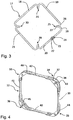
- Fig . 4 shows a perspective view of the ring of the type disclosed in Christensen & Colvard US Patent Publication 2013/0096386 .
- ring 32 has a square formation with rounded corners 33, 34, 35 and 36.
- top plate 37 which forms generally one plane of the ring
- bottom plate 38 which forms generally a second plane of the ring.
- These planes are generally above and below the primary plane of the ring formed by connecting limbs 39, 40, 41 and 42.
- the outer periphery of the top plate and the bottom plate at each corner form a lip feature, which is the entrance of the pockets 43, 44, 45, and 46 that contain a portion of the iris, which is supported in an open configuration.
- Fig. 5 shows an enlarged diagrammatic top view of the ring of the present invention used for enlargement and prevention of collapse of the pupil.
- the ring 47 is made of any resiliently flexible strand, for example, thermally treated 4-0 nylon suture. It is a continuous ring, has a square configuration and has four sides 48, 49, 50 and 51, joined by corner portions. Side 50 has ends 52 and 53 joined at the butt joint 54 with adhesive. Each one of the corner portions 55, 56, 57 and 58, forms a notch, same numerals representing the notches. Corner portion 56 joins side 49 to side 50, which are perpendicular to each other. At the corner portion 56, the strand loops inwards to form a notch.
- the notch has a narrow outward opening 62, which allows iris tissue to enter the notch. Inwards, the notch has a blind, bulbous receptacle 63, which engages the pupillary margin and iris tissue gently. Corner portions 55, 57 and 58 are identical to corner portion 56. Parts 64 and 65 of corner portions 57 and 58 respectively, along with side 51 , form an outward flange. Sides 48, 49 and 50, form similar flanges. The ring comprises alternate notches and flanges, all being in the same plane and enclosing a space 66.
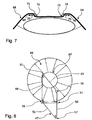
- Fig. 6 shows an illustration of the pupil maintained in an enlarged position by the ring 47 of Fig. 5 .
- the notches at corners 55 , 56 ,. 57 and 58 engage the pupillary margin 67 at different parts and push them apart, causing enlargement of the pupil.
- the flanges at sides 48 and 50 remain in front of the Iris 68.
- the flanges at sides 49 and 51 remain behind the iris and are not visible.
- the alternate notches and flanges cause bending of the pupillary margin and iris tissue somewhat like a paper clip. This results in a secure yet reversible engagement.
- the central opening 66 allows wide view of the structures deeper to the pupillary plane.
- Fig. 7 shows an enlarged diagrammatic side view of the relation of iris tissue to the notches. This side view is at a vertical plane passing through the middle of any two adjacent notches of Fig. 6 .
- the device distinctly bends the iris tissue 68, four times, as it passes through the two notches. From the left as viewed in Fig. 7 , the iris 68 passes above the side element 69 and outer limb 70 of the notch 71.
- the first bend is at an obtuse angle as it passes downwards around the outer limb 70 of the notch 71 and through the notch.
- the second bend is at an obtuse angle to pass under the inner limb 72 of the notch 71.
- Iris 68 then makes a third bend at an obtuse angle as it passes upwards around the inner limb 73 of the notch 74 and through the notch.
- the final fourth bend is at an obtuse angle to pass above the outer limb 75 of the notch 74 and side element 76.
- side element 69, outer limb 70 of the notch 71, the notch 71, inner limb 72 of the notch 71 , inner limb 73 of the notch 74, the notch 74, outer limb 75 of the notch 74 and side element 76 all lie in the same plane.
- Fig . 8 refers to the usage of the invention and is an illustration of the insertion of the ring 47 of Fig. 5 into the eye and engagement of the pupillary margin 67 with the first notch 55 of the ring.
- a forceps (not shown here) carries the device or an injector (not shown here) delivers the device through the incision 77, into the anterior chamber of the eye.
- the flexible square ring 47 adopts a rhomboid configuration as it negotiates through a much smaller incision 77.
- the notches 56 and 58 open up and temporarily straighten out as the device passes through the incision.
- the leading first notch 55 hooks and engages the pupillary margin 67 pushing it in an outward direction.
- the pupillary margin 67 is lifted with a Hirschman hook (not shown here) to tuck the flange 49 under the pupillary margin 67 and iris 68.
- Fig. 9 refers to the usage of the invention in further detail, is an illustration of the stretched pupillary margin after engagement by the second notch 56 of the device 47 of Fig. 5 .
- the resiliently flexible ring 47 has now returned to its square configuration.
- Notches 55 and 56 have engaged the pupillary margin 67 at two different points and pushed them apart.
- Flange 49 (not visible here), remains tucked under the pupillary margin 67, while flanges 48, 50 and 51, remain in front of the iris 68.
- Fig. 10 refers to the usage of the invention in further detail, is an illustration of the pupillary margin 67, fully enlarged and adopting a square configuration after engagement by all four notches 55, 56, 57 and 58 of the device 47 of Fig. 5 .
- the flanges 48 and 50 remain in front of the Iris 68.
- the flanges at sides 49 and 51 remain behind the iris and are not visible.
- the central opening 66 allows wide view of the structures deeper to the pupillary plane.
- the device is easily disengaged from the pupillary margin and pulled out with a forceps.
- the device exits the eye without snagging the incision because notches are in the same plane as the flanges and are capable of straightening temporarily.
- Fig. 11 is an enlarged diagrammatic top view of another form of the device of the present invention, showing a discontinuous ring 78 with ends 79 and 80, which are blunt or olive shaped to prevent damage to delicate structures of the eye.
- the discontinuous ring 78 has five sides 81, 82, 83, 84 and 85, which are shaped like flanges. Corner portions joining these sides are internally obtuse angled.
- the four corner portions 87, 88, 89 and 90 form four notches, same numerals representing the notches.
- Notch 86 is at the first end and notch 91 is at the second end of the ring.
- the angles at corner 87 and 90 are equal to each other and the angles at corner 89 and 90 are equal to each other.
- the first side 81 and the fifth side 85 are parallel to each other, giving the device a flat top house shape.
- the central space 92 is closed on five sides by the device, and open on one side.
- the first side 81 and the fifth side 85 are unparallel, such that the distance between the ends 79 and 80, is more than that between the first corner 87 and fourth corner 90, giving the device the shape of a flat top tower.
- Fig. 12 is an illustration of the pupil maintained in an enlarged position by the device of Fig. 11 .
- the notches 86, 87, 88, 89, 90 and 91 engage the pupillary margin 67 at different parts and push them apart, causing enlargement of the pupil.
- Ends 79 and 80, and flanges 82 and 84 remain in front of the Iris 68.
- the flanges 81, 83 and 85 remain behind the Iris and are not visible.
- the constricting force of the pupil draws the notches at the ends 79 and 80 of the discontinuous ring closer and the resultant shape of the central space 92 of the device and that of the pupil is a hexagon.
- the central space 92 allows wide view of the structures deeper to the pupillary plane.
- the device of Fig. 11 may be inserted into the eye, in the manner described above for the device of Fig. 5 , the device may alternatively be inserted end first, into the eye, through a much smaller side port incision.
- the entire device is inserted into the anterior chamber and placed on the iris.
- the pupillary margin is hooked with an iris or hirschman hook, introduced through one side port incision, while a forceps introduced through another side port, holds flange 83 and tucks it under the pupillary margin 67.
- flanges 81 and 85 are tucked under the pupillary margin.
- Fig. 13 is an enlarged diagrammatic top perspective of one form of the device not falling under the scope of the present invention, showing alternate flanges of the device of Fig. 11 , gently tilted backwards.
- Device 93 allows easier tucking of the flanges under the pupillary margin.
- Flanges 81, 83 and 85 shown in dotted lines, represent the previous straight position of flanges.
- Flanges 94, 95 and 96 represent the backward tilted flanges, respectively.
- the flanges are tilted all the way up to the centre of the notch or only at the peripheral edge.
- the position of flanges 82 and 84, which remain in front of the pupillary margin, is unaltered.
- tilted flanges are shown on the device of the present invention of Fig. 11 , it is understood that such flanges may be present on all the forms of the device.
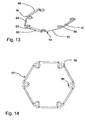
- Fig. 14 is an enlarged diagrammatic top view of one form of the device of the present invention, showing plurality of positioning holes on a hexagon shaped continuous ring with no joint. Holes 98 and 99 are shown on a flange and notch respectively on the device 97. These holes are partial thickness or full thickness. These holes allow easy manipulation of the device inside the eye with the help of a pointed instrument called dialler. Although positioning holes or eyelets are shown on the device of the present invention of Fig. 14 , it is understood that such positioning holes or eyelets may be present on all the forms of the device.
- Fig . 15 is an enlarged diagrammatic top view of one form of the device of the present invention, showing engagement of the pupillary margin 67 by notches formed by an inward loop of the strand between two outward digit shaped protruding loops of the strand of a square shaped continuous ring with no joint.
- the ring 100 has four side elements 101, 102, 103 and 104. Corner portions 105, 106, 107 and 108, join the side elements. Corner portion 108 joins side 101 to side 104, which are perpendicular to each other. At the corner portion 108, the strand makes three distinct loops in the same plane to form a notch. Loops 115 and 116 are outward digit like protrusions.
- Notch 117 is formed by an inward loop between these two outward looped protrusions. Corner portions 105, 106 and 107 are identical to corner portion 108 and form notches 118, 119 and 120 respectively.
- the pupillary margin 67 has a square configuration as it is engaged by the notches 117, 118, 119 and 120, as it passes behind the elements 110, 111, 114 and 115, and in front of elements 112, 113, 116 and 109.
- the enclosed space 121 allows wide view of the structures deeper to the pupillary plane.
- Fig. 16 is an enlarged diagrammatic top view of one form of the device of the present invention, showing engagement of the pupillary margin 67 by two adjacent notches at the corners of a square shaped continuous ring with no joint.
- the ring 122 has four side elements 123, 124, 125 and 126. Corner portions 127, 128 , 129 and 130, join the side elements. Corner portion 127 joins side 123 to side 124, which are perpendicular to each other. At the corner portion 127, the strand makes three distinct loops in the same plane to form two adjacent paired notches or a double notch. Paired notches 131 and 132 are formed by two loops directed inwards.
- a digit like structure 139 is formed between these two notches by a loop directed outwards. Corner portions 128, 129 and 130, are identical to corner portion 127 and form paired notches 133, 134 and 135, 136 and 137, 138 respectively.
- the pupillary margin 67 has a square configuration, engaged by the notches 131, 132, 133, 134, 135, 136, 137 and 138.
- the pupillary margin 67 passes behind side elements 123, 124, 125 and 126, and in front of elements 139, 140, 141 and 142.
- the enclosed space 143 allows wide view of the structures deeper to the pupillary plane.
- the pupillary margin 67 could alternately pass (not shown here) in front of side elements 123 , 124 , 125 and 126, and behind elements 139, 140, 141 and 142.
Description
- The present invention is in the field of ophthalmic surgery and relates to an improvement in the device for mechanical enlargement or dilation of the pupil of the eye during surgery.
- During phacoemulsification surgery and vitreo-retinal surgery, when the pupil does not dilate with medicated drops, a device is required for mechanical enlargement of the pupil. Such a device has to maintain the pupil in the enlarged state and prevent it from collapsing for the entire duration of the surgery. Removal of the device returns the pupil to an unenlarged state to preserve its function and cosmesis. Eyes with non-dilating pupils are often also associated with floppiness of the iris, which poses additional difficulty during surgery.
- In phacoemulsification surgery for cataract, a 1.6 to 2.8 mm incision in the side of the cornea is required to insert a phaco probe. Smaller incisions result in secure and astigmatically neutral wounds translating into better visual outcomes. Vitreo-retinal surgery requires 0.6 mm or smaller incisions in the sclera to insert instruments into the eye. Since a corneal incision is not required, such an incision, only to insert a pupil-dilating device, should be as small as possible.
- Current devices in use for pupillary dilation require a 2.2 to 2.5 mm incision for insertion into the eye. They snag the incision because of gaps or pockets at the corners, which have a biplanar structure with a top and bottom part. Such snagging makes removal of the device difficult and causes damage to the cornea. They require precise alignment to engage the pupillary margin into the small narrow wedge shaped gaps or pockets at the corners. This is particularly difficult because the surgeon has a top view and the device itself obscures view of the narrow gap, which is at the side of the device. The gaps or pockets have two structural planes having an upper and lower part making the comers thick and bulky. The gaps or pockets hold the pupillary margin and iris tissue passively and the pupillary margin can easily disengage during surgical manipulations.
- Such continuous ring devices have been disclosed in
US Patent 8323296, Dec 4 2012 by Malyugin ,US Patent Application publication 2012/0289786, Nov 15 2012 by Dusek andUS Patent Application publication 2013/0096386, Apr 18 2013 by Christensen & Colvard . - Though discontinuous ring devices have been disclosed in
US Patent 5163419, Nov 17 1992 by Goldman ,US Patent 5267553, Dec 7 1993 by Graether ,US Patent 6620098, Sept 16 2003 by Milverton andUS Patent 6648819, Nov 18 2003 by Lee , these devices have not found acceptance because of larger incision size required, cumbersome manipulations involved and loose engagement. - The principal object of the present invention is to provide a device to enlarge the pupil of the eye, which requires a very small incision for insertion into the eye. Another object of the invention is to provide a device with a mechanism to engage the pupillary margin that will not snag the incision during insertion or removal. A further object of the invention is to provide a device, with an easier mechanism to engage the pupillary margin that does not require precise alignment of the pupillary margin into the narrow wedge shaped gaps or pockets at the sides of the device. A further object of the invention is to provide a device, with corners that can engage the pupillary margin but are slim and strictly in the same plane of the device. A further object of the invention is to provide a device, which not only enlarges the pupil, but also remains securely, yet reversibly fastened to iris tissue so that surgical manipulations do not lead to its disengagement. A further object of the invention is to provide a device that reduces floppiness of the iris, which is often associated with non-dilating pupils.
- There is provided a device for enlargement and prevention of collapse of a pupil of an eye during an ophthalmic procedure as defined by the appended claims.
- The device is made of a strand of any resiliently flexible material. Thermally treated 4-0 nylon suture (0.15 to 0.17 mm) is such. Notches temporarily straighten as they pass through the incision allowing the device to be inserted through a very small incision. The device, having no gaps or pockets, being entirely disposed in a single plane, passes through the incision without snagging. The device bends the pupillary margin and iris at the notches and flanges, somewhat like a paper clip, creating a secure engagement. The iris being flexible, can tolerate such bending without any damage. The flanges lying in front of the iris reduce its floppiness by restricting the billowing effect.
- Variations in design may be necessary, to allow the surgeon choices depending on the nature of the surgery, size of the eye, depth of the anterior chamber, associated co-morbidity, size of incision, initial pupil size, desired pupil size etc.
- Variations in design are also necessary to suit different manufacturing capabilities.
- The continuous form of the ring is in the form of a polygon with at least three sides and can be with or without a joint. The ends are joined by knotting or tying of the ends, or by chemical, thermal or ultrasonic bonding of the ends or by any other method. When made by molding, stamping or other methods there is no joint. The discontinuous form of the ring has at least three sides, two corners and four notches. This form requires a much smaller incision for insertion.
- Notches may be formed by an inward loop of the strand at the corners or by an inward loop of the strand between two outward digit shaped protruded loops of the strand. In one form of the invention, the corners of the ring have two adjacent notches.
- Positioning holes on the device help in manipulations of the device. When the device is made of expansible material, it enlarges to a larger size after insertion. The ring device is configured to adapt one or more selected configurations from a folded, extended or deformed configuration, allowing insertion through small incisions.
-
-
Fig. 1 is an enlarged diagrammatic top perspective of the ring of the type disclosed inMalyugin US Patent 8323296, Dec 4, 2012 . -
Fig. 2 is an enlarged diagrammatic side view of ring of the type disclosed inMalyugin US Patent 8323296 , showing iris tissue within the wedge shaped gaps of the loops. -
Fig. 3 is an enlarged diagrammatic top plan of the modified ring of the type disclosed inDusek US Patent Publication 2012/0289786 . -
Fig. 4 is a perspective view of the ring of the type disclosed inChristensen & Colvard US Patent Publication 2013/0096386 . -
Fig. 5 is an enlarged diagrammatic top view of one form of the device of the present invention, showing a square shaped continuous ring with a joint. -
Fig. 6 is an illustration of the pupil maintained in an enlarged position by the device ofFig. 5 . -
Fig. 7 is an enlarged diagrammatic side view showing the relation of iris tissue to the notches. -
Fig. 8 is an illustration of the insertion of the ring device into the eye and engagement of the pupillary margin with the first notch of the device ofFig. 5 . -
Fig. 9 is an illustration of the stretched pupillary margin after engagement by the second notch of the device ofFig. 5 . -
Fig. 10 is an illustration of the pupil fully enlarged after engagement by all four notches of the device ofFig. 5 . -
Fig. 11 is an enlarged diagrammatic top view of one form of the device of the present invention, showing a discontinuous ring with five sides, four corners and six notches. -
Fig. 12 is an illustration of the pupil maintained in an enlarged position by the device ofFig. 11 . -
Fig. 13 is an enlarged diagrammatic top perspective of one form of the device r not falling under the scope of - the present invention, showing alternate flanges of the device of
Fig. 11 , gently tilted backwards. -
Fig. 14 is an enlarged diagrammatic top view of one form of the device of the present invention, showing plurality of positioning holes on a hexagon shaped continuous ring with no joint. -
Fig. 15 is an enlarged diagrammatic top view of one form of the device of the present invention, showing engagement of the pupillary margin by notches formed by an inward loop of the strand between two outward digit shaped protruding loops of the strand of a square shaped continuous ring with no joint. -
Fig. 16 is an enlarged diagrammatic top view of one form of the device of the present invention, showing engagement of the pupillary margin by two adjacent notches at the corners of a square shaped continuous ring with no joint. - The relevant features of existing devices and the novelty of the present invention, is illustrated in the accompanying drawings, throughout which, like reference numerals indicate corresponding parts in the various figures.
-
Fig. 1 shows an enlarged diagrammatic top perspective of the ring of the type disclosed inMalyugin US Patent 8323296, . TheDec 4, 2012Malyugin ring 1 has a square configuration with fourhelical loops sides gap ring 1 maintains the pupil in an extended position while thecentral opening 15 provides a wide viewing area during surgery. -
Fig. 2 shows an enlarged diagrammatic side view of ring of the type disclosed inMalyugin US Patent 8323296 , showingiris tissue 16 within the wedge shapedgaps side 9 connects the bottom part ofgap 13, which is at one plane, to the top part ofgap 14, which is at another plane. -
Fig. 3 shows an enlarged diagrammatic top plan of the modified ring of the type disclosed inDusek US Patent Publication 2012/0289786 . TheDusek ring 17 has foursides Side 20 has the end butt joint 22 where a drop of adhesive secures theends Side 19 is perpendicular toside 20. The sides are joined by acorner portion 25 which has three distinct bends, namely, a first obtuse bend 26 (essentially 135° inward and to the left as viewed inFig. 3 ), second return bend 27 (essentially 180° inward and then down away from the viewer and then toward the right as viewed inFig. 3 ), and a third obtuse bend 28 (essentially 135° up and to the left as viewed inFig. 3 ).Corner portions portion 25. -
Fig. 4 shows a perspective view of the ring of the type disclosed inChristensen & Colvard US Patent Publication 2013/0096386 . In the described embodiment of this disclosure,ring 32 has a square formation withrounded corners top plate 37, which forms generally one plane of the ring and there is abottom plate 38, which forms generally a second plane of the ring. These planes are generally above and below the primary plane of the ring formed by connectinglimbs pockets - The devices of
Figs. 1-4 do not fall under the scope of the present invention. -
Fig. 5 shows an enlarged diagrammatic top view of the ring of the present invention used for enlargement and prevention of collapse of the pupil. Thering 47 is made of any resiliently flexible strand, for example, thermally treated 4-0 nylon suture. It is a continuous ring, has a square configuration and has foursides Side 50 has ends 52 and 53 joined at the butt joint 54 with adhesive. Each one of thecorner portions Corner portion 56 joinsside 49 toside 50, which are perpendicular to each other. At thecorner portion 56, the strand loops inwards to form a notch. Three distinct bends of the strand in the same plane form the notch. A firstacute bend 59, secondrounded return bend 60, and a thirdacute bend 61. The notch has a narrowoutward opening 62, which allows iris tissue to enter the notch. Inwards, the notch has a blind,bulbous receptacle 63, which engages the pupillary margin and iris tissue gently.Corner portions portion 56.Parts corner portions side 51, form an outward flange.Sides space 66. -
Fig. 6 shows an illustration of the pupil maintained in an enlarged position by thering 47 ofFig. 5 . The notches atcorners pupillary margin 67 at different parts and push them apart, causing enlargement of the pupil. The flanges atsides Iris 68. The flanges atsides central opening 66, allows wide view of the structures deeper to the pupillary plane. -
Fig. 7 shows an enlarged diagrammatic side view of the relation of iris tissue to the notches. This side view is at a vertical plane passing through the middle of any two adjacent notches ofFig. 6 . The device distinctly bends theiris tissue 68, four times, as it passes through the two notches. From the left as viewed inFig. 7 , theiris 68 passes above theside element 69 andouter limb 70 of thenotch 71. The first bend is at an obtuse angle as it passes downwards around theouter limb 70 of thenotch 71 and through the notch. The second bend is at an obtuse angle to pass under theinner limb 72 of thenotch 71.Iris 68 then makes a third bend at an obtuse angle as it passes upwards around theinner limb 73 of thenotch 74 and through the notch. The final fourth bend is at an obtuse angle to pass above theouter limb 75 of thenotch 74 andside element 76. As viewed inFig. 7 ,side element 69,outer limb 70 of thenotch 71, thenotch 71,inner limb 72 of thenotch 71,inner limb 73 of thenotch 74, thenotch 74,outer limb 75 of thenotch 74 andside element 76, all lie in the same plane. -
Fig. 8 refers to the usage of the invention and is an illustration of the insertion of thering 47 ofFig. 5 into the eye and engagement of thepupillary margin 67 with thefirst notch 55 of the ring. A forceps (not shown here) carries the device or an injector (not shown here) delivers the device through theincision 77, into the anterior chamber of the eye. The flexiblesquare ring 47 adopts a rhomboid configuration as it negotiates through a muchsmaller incision 77. Thenotches first notch 55 hooks and engages thepupillary margin 67 pushing it in an outward direction. Thepupillary margin 67 is lifted with a Hirschman hook (not shown here) to tuck theflange 49 under thepupillary margin 67 andiris 68. -
Fig. 9 refers to the usage of the invention in further detail, is an illustration of the stretched pupillary margin after engagement by thesecond notch 56 of thedevice 47 ofFig. 5 . The resilientlyflexible ring 47 has now returned to its square configuration.Notches pupillary margin 67 at two different points and pushed them apart. Flange 49 (not visible here), remains tucked under thepupillary margin 67, whileflanges iris 68. As the pupillary margin is hooked again with an iris or hirschman hook, introduced through a side port (not shown here), a forceps introduced through another side port (not shown here), holds theflange 51 and tucks it under thepupillary margin 67 andiris 68. -
Fig. 10 refers to the usage of the invention in further detail, is an illustration of thepupillary margin 67, fully enlarged and adopting a square configuration after engagement by all fournotches device 47 ofFig. 5 . Theflanges Iris 68. The flanges atsides central opening 66, allows wide view of the structures deeper to the pupillary plane. On completion of surgery, the device is easily disengaged from the pupillary margin and pulled out with a forceps. The device exits the eye without snagging the incision because notches are in the same plane as the flanges and are capable of straightening temporarily. -
Fig. 11 is an enlarged diagrammatic top view of another form of the device of the present invention, showing adiscontinuous ring 78 withends discontinuous ring 78 has fivesides corner portions Notch 86 is at the first end and notch 91 is at the second end of the ring. In the device ofFig. 11 , the angles atcorner corner first side 81 and thefifth side 85 are parallel to each other, giving the device a flat top house shape. Thecentral space 92, is closed on five sides by the device, and open on one side. In another form of the device ofFig. 11 (not shown here), thefirst side 81 and thefifth side 85, are unparallel, such that the distance between theends first corner 87 andfourth corner 90, giving the device the shape of a flat top tower. -
Fig. 12 is an illustration of the pupil maintained in an enlarged position by the device ofFig. 11 . Thenotches pupillary margin 67 at different parts and push them apart, causing enlargement of the pupil. Ends 79 and 80, andflanges Iris 68. Theflanges ends central space 92 of the device and that of the pupil is a hexagon. Thecentral space 92, allows wide view of the structures deeper to the pupillary plane. While the device ofFig. 11 may be inserted into the eye, in the manner described above for the device ofFig. 5 , the device may alternatively be inserted end first, into the eye, through a much smaller side port incision. The entire device is inserted into the anterior chamber and placed on the iris. The pupillary margin is hooked with an iris or hirschman hook, introduced through one side port incision, while a forceps introduced through another side port, holdsflange 83 and tucks it under thepupillary margin 67. Similarly,flanges -
Fig. 13 is an enlarged diagrammatic top perspective of one form of the device not falling under the scope of the present invention, showing alternate flanges of the device ofFig. 11 , gently tilted backwards.Device 93 allows easier tucking of the flanges under the pupillary margin.Flanges Flanges flanges Fig. 11 , it is understood that such flanges may be present on all the forms of the device. -
Fig. 14 is an enlarged diagrammatic top view of one form of the device of the present invention, showing plurality of positioning holes on a hexagon shaped continuous ring with no joint.Holes device 97. These holes are partial thickness or full thickness. These holes allow easy manipulation of the device inside the eye with the help of a pointed instrument called dialler. Although positioning holes or eyelets are shown on the device of the present invention ofFig. 14 , it is understood that such positioning holes or eyelets may be present on all the forms of the device. -
Fig. 15 is an enlarged diagrammatic top view of one form of the device of the present invention, showing engagement of thepupillary margin 67 by notches formed by an inward loop of the strand between two outward digit shaped protruding loops of the strand of a square shaped continuous ring with no joint. Thering 100 has fourside elements Corner portions Corner portion 108 joinsside 101 toside 104, which are perpendicular to each other. At thecorner portion 108, the strand makes three distinct loops in the same plane to form a notch.Loops Notch 117, is formed by an inward loop between these two outward looped protrusions.Corner portions corner portion 108 andform notches pupillary margin 67 has a square configuration as it is engaged by thenotches elements elements enclosed space 121, allows wide view of the structures deeper to the pupillary plane. -
Fig. 16 is an enlarged diagrammatic top view of one form of the device of the present invention, showing engagement of thepupillary margin 67 by two adjacent notches at the corners of a square shaped continuous ring with no joint. Thering 122 has fourside elements Corner portions Corner portion 127 joinsside 123 toside 124, which are perpendicular to each other. At thecorner portion 127, the strand makes three distinct loops in the same plane to form two adjacent paired notches or a double notch. Pairednotches structure 139, is formed between these two notches by a loop directed outwards.Corner portions corner portion 127 and form pairednotches pupillary margin 67 has a square configuration, engaged by thenotches pupillary margin 67 passes behindside elements elements enclosed space 143, allows wide view of the structures deeper to the pupillary plane. Thepupillary margin 67 could alternately pass (not shown here) in front ofside elements elements - Those ordinarily skilled in the art can make changes in the embodiments described and illustrated, without altering the concepts of the present invention. Hence, it is to be understood that the invention is not limited to the descriptions, illustrations and examples.
Claims (14)
- A device for enlargement and prevention of collapse of a pupil of an eye during an ophthalmic procedure, the device configured as a ring (47, 78, 97, 100, 122) comprising:a strand of resiliently flexible material forming at least three notches (55-58, 86-91, 117-120, 131-138) and two side elements (48-51, 81-85, 101-104, 123-126), said notches being open outwards with a blind receptacle inwards (63), each notch comprising a first acute bend (59), a second rounded return bend (60) and a third acute bend (61), characterised in that the at least three notches and two side elements are disposed within the same plane.
- The device of claim 1, wherein said ring has side elements shaped like flanges (64, 65), said flanges being formed by a loop of the strand, flanges being directed outwards, wherein in use, a pupillary margin and iris of an eye can be bent above or below alternate flanges.
- The device of claim 1, wherein said notches being formed by inward looping of the strand.
- The device of any of claims 1, 2 or 3, wherein said ring (47, 97, 100, 122) is continuous, formed by joining the two ends (52, 53) of a discontinuous ring or continuous, with no joints.
- The device of claim 4, wherein said continuous ring (47, 97, 100, 122) has a polygonal shape, having at least three sides and three corners.
- The device of claim 5, wherein said ring (47, 100, 122) is shaped as a rectangle or square, with a notch being at each of the four corners.
- The device of claim 5, wherein said ring (97) is shaped as a hexagon, with a notch being at each of the six corners.
- The device of claim 1, wherein said ring (78) is discontinuous, having at least three sides and two corners, the ends (79, 80) of the ring being blunted or olive shaped.
- The device of claim 8, wherein said discontinuous ring (78) comprises two ends, five sides, four corners and six notches, said notches being at the two ends and four corners, said corners being internally obtuse angled, wherein the distance between the two ends of the ring is more than that between the first and fourth corners.
- The device of any one of claims 5 to 9, wherein said ring (97) has one or more positioning holes or eyelets (98, 99) on the notches, side elements or ends.
- The device of any one of claims 5 to 10, wherein one or more notch of the said ring is shaped like a bulb, flask, keyhole, hockey stick, omega, U, V, L, S, incomplete rectangle or incomplete polygon, all notches on a given device being similar or dissimilar.
- The device of any one of claims 5 to 11, wherein at least one of the corners (127-130) of the ring (122) has two adjacent notches (131-138).
- The device of any one of claims 5 to 12, wherein said ring (47, 78, 97, 100, 122) is expansible, being capable of enlarging or being enlarged.
- The device of any one of claims 5 to 13, wherein said ring (47, 78, 97, 100, 122) is configured to adapt one or more selected configurations from a folded, extended or deformed configuration.
Applications Claiming Priority (2)
| Application Number | Priority Date | Filing Date | Title |
|---|---|---|---|
| IN225KO2013 | 2013-02-27 | ||
| PCT/IN2013/000457 WO2014132264A1 (en) | 2013-02-27 | 2013-07-23 | Device providing enlargement & preventing collapse of the pupil of the eye |
Publications (2)
| Publication Number | Publication Date |
|---|---|
| EP2961329A1 EP2961329A1 (en) | 2016-01-06 |
| EP2961329B1 true EP2961329B1 (en) | 2018-02-21 |
Family
ID=49293802
Family Applications (1)
| Application Number | Title | Priority Date | Filing Date |
|---|---|---|---|
| EP13771217.0A Active EP2961329B1 (en) | 2013-02-27 | 2013-07-23 | Device providing enlargement and preventing collapse of the pupil of the eye |
Country Status (11)
| Country | Link |
|---|---|
| US (1) | US10080558B2 (en) |
| EP (1) | EP2961329B1 (en) |
| JP (1) | JP6233728B2 (en) |
| KR (1) | KR101865629B1 (en) |
| CN (1) | CN105142535B (en) |
| AU (1) | AU2013380203B2 (en) |
| CA (1) | CA2902800C (en) |
| ES (1) | ES2668292T3 (en) |
| HK (1) | HK1218703A1 (en) |
| SG (1) | SG11201508026RA (en) |
| WO (1) | WO2014132264A1 (en) |
Families Citing this family (9)
| Publication number | Priority date | Publication date | Assignee | Title |
|---|---|---|---|---|
| US9918710B2 (en) | 2007-03-15 | 2018-03-20 | Microsurgical Technology, Inc. | Expansion ring for eyeball tissue |
| US8323296B2 (en) * | 2007-03-15 | 2012-12-04 | Boris Malyugin | Ring used in a small pupil phacoemulsification procedure |
| KR101865629B1 (en) | 2013-02-27 | 2018-06-11 | 수벤 바타챠르지 | Device providing enlargement & preventing collapse of the pupil of the eye |
| US10307150B2 (en) * | 2014-06-26 | 2019-06-04 | The Regents Of The University Of Colorado, A Body Corporate | Ocular tissue expansion ring |
| US9504459B1 (en) | 2015-06-30 | 2016-11-29 | Ravi Nallakrishnan Revocable Trust | Surgical apparatus and method of use thereof |
| KR102211425B1 (en) * | 2017-10-16 | 2021-02-04 | 서울대학교산학협력단 | Wound protector for surgery |
| US11759101B2 (en) * | 2019-03-15 | 2023-09-19 | Modern Surgical Solutions Llc | Retractor for vaginal repair |
| CN109998613A (en) * | 2019-04-19 | 2019-07-12 | 郑州大学第一附属医院 | The iris extension fixture of corneal incision wound can be reduced |
| CN112998784A (en) * | 2021-03-04 | 2021-06-22 | 中国人民解放军陆军军医大学第一附属医院 | External incision opening and stabilizing device |
Family Cites Families (28)
| Publication number | Priority date | Publication date | Assignee | Title |
|---|---|---|---|---|
| US4037589A (en) | 1975-10-03 | 1977-07-26 | William U. McReynolds | Ocular surgical system |
| US4321916A (en) | 1980-03-26 | 1982-03-30 | Mckee Douglas C | Eyelid retractor |
| US4782820A (en) | 1987-10-22 | 1988-11-08 | Woods Randall L | Iris retaining device |
| US5163419A (en) | 1991-04-04 | 1992-11-17 | Goldman Kenneth N | Device for expanding the pupil of a human eye |
| US5318011A (en) | 1992-02-04 | 1994-06-07 | Escalon Ophthalmics, Inc. | Iris protector/dilator and method of using the same |
| US5267553A (en) | 1992-02-18 | 1993-12-07 | Graether John M | Pupil expander and method of using the same |
| US5299564A (en) | 1992-09-23 | 1994-04-05 | Kabi Pharmacia Ophthalmics Inc. | Expandable dilator and method for intraocular surgery |
| US5374272A (en) * | 1993-06-29 | 1994-12-20 | Vitrophage, Inc. | Apparatus and method for mechanically dilating the pupil of an eye |
| AUPP747398A0 (en) * | 1998-12-03 | 1998-12-24 | Milvella Pty Ltd | Device for dilating a pupil and/or maintaining a pupil in a dilated state |
| US6648819B2 (en) | 2001-11-15 | 2003-11-18 | Yau Wing Lee | Pupil dilator |
| US7985180B2 (en) * | 2006-11-08 | 2011-07-26 | Reay H Brown | Eyelid retractor |
| US9918710B2 (en) * | 2007-03-15 | 2018-03-20 | Microsurgical Technology, Inc. | Expansion ring for eyeball tissue |
| US20080243139A1 (en) | 2007-03-15 | 2008-10-02 | Vaclav Dusek | Method for assembling a ring used in a small pupil phaco procedure |
| US20120289786A1 (en) * | 2010-11-09 | 2012-11-15 | Microsurgical Technology, Inc. | Extension ring for eyeball tissue |
| US8323296B2 (en) | 2007-03-15 | 2012-12-04 | Boris Malyugin | Ring used in a small pupil phacoemulsification procedure |
| US9610072B2 (en) | 2009-11-02 | 2017-04-04 | Apx Opthalmology Ltd. | Iris retractor |
| AU2010313159B2 (en) * | 2009-11-02 | 2016-01-21 | Apx Ophthalmology Ltd. | Iris retractor |
| CN103180435A (en) | 2010-08-31 | 2013-06-26 | 库克通用生物技术有限责任公司 | Systemic, allogenic stem cell therapies for treatment of diseases in animals |
| WO2012037550A1 (en) * | 2010-09-17 | 2012-03-22 | Henry Ford Health System | Pupil ring |
| US8439833B2 (en) | 2011-10-18 | 2013-05-14 | Oasis Medical, Inc. | Ophthalmic structure |
| US8852091B2 (en) | 2012-04-04 | 2014-10-07 | Alcon Research, Ltd. | Devices, systems, and methods for pupil expansion |
| US8496583B1 (en) * | 2012-11-03 | 2013-07-30 | Michael Reynard | Pupil dilation system |
| US20140221759A1 (en) | 2013-02-06 | 2014-08-07 | Impex, Inc. | Pupil expansion apparatus |
| US20150164685A1 (en) | 2013-02-27 | 2015-06-18 | Suven Bhattacharjee | Pupil expansion device |
| KR101865629B1 (en) | 2013-02-27 | 2018-06-11 | 수벤 바타챠르지 | Device providing enlargement & preventing collapse of the pupil of the eye |
| CN105188514B (en) | 2013-03-15 | 2017-05-10 | 碧维-韦斯泰科国际(美国)股份有限公司 | Iris expander |
| JP5528600B1 (en) | 2013-03-29 | 2014-06-25 | 株式会社Frontier Vision | Pupil dilator |
| US20140378773A1 (en) | 2013-06-19 | 2014-12-25 | Ronald Dykes | Intraocular Expansion and Retention Devices and Methods |
-
2013
- 2013-07-23 KR KR1020157026927A patent/KR101865629B1/en active IP Right Grant
- 2013-07-23 SG SG11201508026RA patent/SG11201508026RA/en unknown
- 2013-07-23 ES ES13771217.0T patent/ES2668292T3/en active Active
- 2013-07-23 CA CA2902800A patent/CA2902800C/en active Active
- 2013-07-23 US US14/379,684 patent/US10080558B2/en active Active
- 2013-07-23 JP JP2015559604A patent/JP6233728B2/en active Active
- 2013-07-23 AU AU2013380203A patent/AU2013380203B2/en active Active
- 2013-07-23 WO PCT/IN2013/000457 patent/WO2014132264A1/en active Application Filing
- 2013-07-23 CN CN201380075982.4A patent/CN105142535B/en active Active
- 2013-07-23 EP EP13771217.0A patent/EP2961329B1/en active Active
-
2016
- 2016-06-10 HK HK16106689.5A patent/HK1218703A1/en unknown
Also Published As
| Publication number | Publication date |
|---|---|
| JP6233728B2 (en) | 2017-11-22 |
| SG11201508026RA (en) | 2015-10-29 |
| CN105142535B (en) | 2017-12-29 |
| CA2902800A1 (en) | 2014-09-04 |
| AU2013380203A1 (en) | 2015-10-22 |
| KR101865629B1 (en) | 2018-06-11 |
| US10080558B2 (en) | 2018-09-25 |
| EP2961329A1 (en) | 2016-01-06 |
| CA2902800C (en) | 2018-03-13 |
| KR20150128762A (en) | 2015-11-18 |
| HK1218703A1 (en) | 2017-03-10 |
| JP2016511680A (en) | 2016-04-21 |
| CN105142535A (en) | 2015-12-09 |
| ES2668292T3 (en) | 2018-05-17 |
| WO2014132264A1 (en) | 2014-09-04 |
| AU2013380203B2 (en) | 2017-04-06 |
| US20150351736A1 (en) | 2015-12-10 |
Similar Documents
| Publication | Publication Date | Title |
|---|---|---|
| EP2961329B1 (en) | Device providing enlargement and preventing collapse of the pupil of the eye | |
| US20150164685A1 (en) | Pupil expansion device | |
| US8439833B2 (en) | Ophthalmic structure | |
| US11219438B2 (en) | Expansion ring for eyeball tissue | |
| US7666190B2 (en) | Holder of contact lens for vitreous body operation, and holding part and connection part of contact lens for vitreous body operation | |
| US9986991B2 (en) | Surgical apparatus and method of use thereof | |
| EP3158974A1 (en) | Intraocular lens | |
| JP5528600B1 (en) | Pupil dilator | |
| US10307150B2 (en) | Ocular tissue expansion ring | |
| JP5398092B1 (en) | Intraocular lens | |
| JP2020005979A (en) | Ophthalmic surgical instrument | |
| WO2014172714A1 (en) | Support segment for ocular structures | |
| JP6885623B2 (en) | Mirror body |
Legal Events
| Date | Code | Title | Description |
|---|---|---|---|
| PUAI | Public reference made under article 153(3) epc to a published international application that has entered the european phase |
Free format text: ORIGINAL CODE: 0009012 |
|
| 17P | Request for examination filed |
Effective date: 20150921 |
|
| AK | Designated contracting states |
Kind code of ref document: A1 Designated state(s): AL AT BE BG CH CY CZ DE DK EE ES FI FR GB GR HR HU IE IS IT LI LT LU LV MC MK MT NL NO PL PT RO RS SE SI SK SM TR |
|
| AX | Request for extension of the european patent |
Extension state: BA ME |
|
| DAX | Request for extension of the european patent (deleted) | ||
| STAA | Information on the status of an ep patent application or granted ep patent |
Free format text: STATUS: EXAMINATION IS IN PROGRESS |
|
| 17Q | First examination report despatched |
Effective date: 20161213 |
|
| GRAP | Despatch of communication of intention to grant a patent |
Free format text: ORIGINAL CODE: EPIDOSNIGR1 |
|
| STAA | Information on the status of an ep patent application or granted ep patent |
Free format text: STATUS: GRANT OF PATENT IS INTENDED |
|
| INTG | Intention to grant announced |
Effective date: 20170918 |
|
| RAP1 | Party data changed (applicant data changed or rights of an application transferred) |
Owner name: MED INVENT DEVICES PRIVATE LIMITED |
|
| RIN1 | Information on inventor provided before grant (corrected) |
Inventor name: BHATTACHARJEE, SUVEN |
|
| GRAS | Grant fee paid |
Free format text: ORIGINAL CODE: EPIDOSNIGR3 |
|
| GRAA | (expected) grant |
Free format text: ORIGINAL CODE: 0009210 |
|
| STAA | Information on the status of an ep patent application or granted ep patent |
Free format text: STATUS: THE PATENT HAS BEEN GRANTED |
|
| AK | Designated contracting states |
Kind code of ref document: B1 Designated state(s): AL AT BE BG CH CY CZ DE DK EE ES FI FR GB GR HR HU IE IS IT LI LT LU LV MC MK MT NL NO PL PT RO RS SE SI SK SM TR |
|
| REG | Reference to a national code |
Ref country code: GB Ref legal event code: FG4D |
|
| REG | Reference to a national code |
Ref country code: CH Ref legal event code: EP |
|
| REG | Reference to a national code |
Ref country code: AT Ref legal event code: REF Ref document number: 970818 Country of ref document: AT Kind code of ref document: T Effective date: 20180315 |
|
| REG | Reference to a national code |
Ref country code: IE Ref legal event code: FG4D |
|
| REG | Reference to a national code |
Ref country code: DE Ref legal event code: R096 Ref document number: 602013033382 Country of ref document: DE |
|
| REG | Reference to a national code |
Ref country code: CH Ref legal event code: NV Representative=s name: MICHELI AND CIE SA, CH |
|
| REG | Reference to a national code |
Ref country code: ES Ref legal event code: FG2A Ref document number: 2668292 Country of ref document: ES Kind code of ref document: T3 Effective date: 20180517 |
|
| REG | Reference to a national code |
Ref country code: NL Ref legal event code: FP |
|
| REG | Reference to a national code |
Ref country code: FR Ref legal event code: PLFP Year of fee payment: 6 |
|
| REG | Reference to a national code |
Ref country code: LT Ref legal event code: MG4D |
|
| REG | Reference to a national code |
Ref country code: AT Ref legal event code: MK05 Ref document number: 970818 Country of ref document: AT Kind code of ref document: T Effective date: 20180221 |
|
| PG25 | Lapsed in a contracting state [announced via postgrant information from national office to epo] |
Ref country code: LT Free format text: LAPSE BECAUSE OF FAILURE TO SUBMIT A TRANSLATION OF THE DESCRIPTION OR TO PAY THE FEE WITHIN THE PRESCRIBED TIME-LIMIT Effective date: 20180221 Ref country code: HR Free format text: LAPSE BECAUSE OF FAILURE TO SUBMIT A TRANSLATION OF THE DESCRIPTION OR TO PAY THE FEE WITHIN THE PRESCRIBED TIME-LIMIT Effective date: 20180221 Ref country code: NO Free format text: LAPSE BECAUSE OF FAILURE TO SUBMIT A TRANSLATION OF THE DESCRIPTION OR TO PAY THE FEE WITHIN THE PRESCRIBED TIME-LIMIT Effective date: 20180521 Ref country code: CY Free format text: LAPSE BECAUSE OF FAILURE TO SUBMIT A TRANSLATION OF THE DESCRIPTION OR TO PAY THE FEE WITHIN THE PRESCRIBED TIME-LIMIT Effective date: 20180221 Ref country code: FI Free format text: LAPSE BECAUSE OF FAILURE TO SUBMIT A TRANSLATION OF THE DESCRIPTION OR TO PAY THE FEE WITHIN THE PRESCRIBED TIME-LIMIT Effective date: 20180221 |
|
| PG25 | Lapsed in a contracting state [announced via postgrant information from national office to epo] |
Ref country code: AT Free format text: LAPSE BECAUSE OF FAILURE TO SUBMIT A TRANSLATION OF THE DESCRIPTION OR TO PAY THE FEE WITHIN THE PRESCRIBED TIME-LIMIT Effective date: 20180221 Ref country code: SE Free format text: LAPSE BECAUSE OF FAILURE TO SUBMIT A TRANSLATION OF THE DESCRIPTION OR TO PAY THE FEE WITHIN THE PRESCRIBED TIME-LIMIT Effective date: 20180221 Ref country code: LV Free format text: LAPSE BECAUSE OF FAILURE TO SUBMIT A TRANSLATION OF THE DESCRIPTION OR TO PAY THE FEE WITHIN THE PRESCRIBED TIME-LIMIT Effective date: 20180221 Ref country code: BG Free format text: LAPSE BECAUSE OF FAILURE TO SUBMIT A TRANSLATION OF THE DESCRIPTION OR TO PAY THE FEE WITHIN THE PRESCRIBED TIME-LIMIT Effective date: 20180521 Ref country code: RS Free format text: LAPSE BECAUSE OF FAILURE TO SUBMIT A TRANSLATION OF THE DESCRIPTION OR TO PAY THE FEE WITHIN THE PRESCRIBED TIME-LIMIT Effective date: 20180221 Ref country code: GR Free format text: LAPSE BECAUSE OF FAILURE TO SUBMIT A TRANSLATION OF THE DESCRIPTION OR TO PAY THE FEE WITHIN THE PRESCRIBED TIME-LIMIT Effective date: 20180522 |
|
| PG25 | Lapsed in a contracting state [announced via postgrant information from national office to epo] |
Ref country code: AL Free format text: LAPSE BECAUSE OF FAILURE TO SUBMIT A TRANSLATION OF THE DESCRIPTION OR TO PAY THE FEE WITHIN THE PRESCRIBED TIME-LIMIT Effective date: 20180221 Ref country code: RO Free format text: LAPSE BECAUSE OF FAILURE TO SUBMIT A TRANSLATION OF THE DESCRIPTION OR TO PAY THE FEE WITHIN THE PRESCRIBED TIME-LIMIT Effective date: 20180221 Ref country code: EE Free format text: LAPSE BECAUSE OF FAILURE TO SUBMIT A TRANSLATION OF THE DESCRIPTION OR TO PAY THE FEE WITHIN THE PRESCRIBED TIME-LIMIT Effective date: 20180221 Ref country code: PL Free format text: LAPSE BECAUSE OF FAILURE TO SUBMIT A TRANSLATION OF THE DESCRIPTION OR TO PAY THE FEE WITHIN THE PRESCRIBED TIME-LIMIT Effective date: 20180221 |
|
| REG | Reference to a national code |
Ref country code: DE Ref legal event code: R097 Ref document number: 602013033382 Country of ref document: DE |
|
| PG25 | Lapsed in a contracting state [announced via postgrant information from national office to epo] |
Ref country code: SK Free format text: LAPSE BECAUSE OF FAILURE TO SUBMIT A TRANSLATION OF THE DESCRIPTION OR TO PAY THE FEE WITHIN THE PRESCRIBED TIME-LIMIT Effective date: 20180221 Ref country code: DK Free format text: LAPSE BECAUSE OF FAILURE TO SUBMIT A TRANSLATION OF THE DESCRIPTION OR TO PAY THE FEE WITHIN THE PRESCRIBED TIME-LIMIT Effective date: 20180221 Ref country code: CZ Free format text: LAPSE BECAUSE OF FAILURE TO SUBMIT A TRANSLATION OF THE DESCRIPTION OR TO PAY THE FEE WITHIN THE PRESCRIBED TIME-LIMIT Effective date: 20180221 Ref country code: SM Free format text: LAPSE BECAUSE OF FAILURE TO SUBMIT A TRANSLATION OF THE DESCRIPTION OR TO PAY THE FEE WITHIN THE PRESCRIBED TIME-LIMIT Effective date: 20180221 |
|
| PLBE | No opposition filed within time limit |
Free format text: ORIGINAL CODE: 0009261 |
|
| STAA | Information on the status of an ep patent application or granted ep patent |
Free format text: STATUS: NO OPPOSITION FILED WITHIN TIME LIMIT |
|
| 26N | No opposition filed |
Effective date: 20181122 |
|
| PG25 | Lapsed in a contracting state [announced via postgrant information from national office to epo] |
Ref country code: SI Free format text: LAPSE BECAUSE OF FAILURE TO SUBMIT A TRANSLATION OF THE DESCRIPTION OR TO PAY THE FEE WITHIN THE PRESCRIBED TIME-LIMIT Effective date: 20180221 |
|
| PG25 | Lapsed in a contracting state [announced via postgrant information from national office to epo] |
Ref country code: MC Free format text: LAPSE BECAUSE OF FAILURE TO SUBMIT A TRANSLATION OF THE DESCRIPTION OR TO PAY THE FEE WITHIN THE PRESCRIBED TIME-LIMIT Effective date: 20180221 Ref country code: LU Free format text: LAPSE BECAUSE OF NON-PAYMENT OF DUE FEES Effective date: 20180723 |
|
| REG | Reference to a national code |
Ref country code: BE Ref legal event code: MM Effective date: 20180731 |
|
| REG | Reference to a national code |
Ref country code: IE Ref legal event code: MM4A |
|
| PG25 | Lapsed in a contracting state [announced via postgrant information from national office to epo] |
Ref country code: IE Free format text: LAPSE BECAUSE OF NON-PAYMENT OF DUE FEES Effective date: 20180723 |
|
| PG25 | Lapsed in a contracting state [announced via postgrant information from national office to epo] |
Ref country code: BE Free format text: LAPSE BECAUSE OF NON-PAYMENT OF DUE FEES Effective date: 20180731 |
|
| PG25 | Lapsed in a contracting state [announced via postgrant information from national office to epo] |
Ref country code: MT Free format text: LAPSE BECAUSE OF NON-PAYMENT OF DUE FEES Effective date: 20180723 |
|
| PG25 | Lapsed in a contracting state [announced via postgrant information from national office to epo] |
Ref country code: TR Free format text: LAPSE BECAUSE OF FAILURE TO SUBMIT A TRANSLATION OF THE DESCRIPTION OR TO PAY THE FEE WITHIN THE PRESCRIBED TIME-LIMIT Effective date: 20180221 |
|
| PG25 | Lapsed in a contracting state [announced via postgrant information from national office to epo] |
Ref country code: PT Free format text: LAPSE BECAUSE OF FAILURE TO SUBMIT A TRANSLATION OF THE DESCRIPTION OR TO PAY THE FEE WITHIN THE PRESCRIBED TIME-LIMIT Effective date: 20180221 |
|
| PG25 | Lapsed in a contracting state [announced via postgrant information from national office to epo] |
Ref country code: MK Free format text: LAPSE BECAUSE OF NON-PAYMENT OF DUE FEES Effective date: 20180221 Ref country code: HU Free format text: LAPSE BECAUSE OF FAILURE TO SUBMIT A TRANSLATION OF THE DESCRIPTION OR TO PAY THE FEE WITHIN THE PRESCRIBED TIME-LIMIT; INVALID AB INITIO Effective date: 20130723 |
|
| PG25 | Lapsed in a contracting state [announced via postgrant information from national office to epo] |
Ref country code: IS Free format text: LAPSE BECAUSE OF FAILURE TO SUBMIT A TRANSLATION OF THE DESCRIPTION OR TO PAY THE FEE WITHIN THE PRESCRIBED TIME-LIMIT Effective date: 20180621 |
|
| PGFP | Annual fee paid to national office [announced via postgrant information from national office to epo] |
Ref country code: NL Payment date: 20230724 Year of fee payment: 11 |
|
| PGFP | Annual fee paid to national office [announced via postgrant information from national office to epo] |
Ref country code: IT Payment date: 20230630 Year of fee payment: 11 Ref country code: GB Payment date: 20230630 Year of fee payment: 11 Ref country code: ES Payment date: 20230804 Year of fee payment: 11 Ref country code: CH Payment date: 20230801 Year of fee payment: 11 |
|
| PGFP | Annual fee paid to national office [announced via postgrant information from national office to epo] |
Ref country code: FR Payment date: 20230725 Year of fee payment: 11 Ref country code: DE Payment date: 20230630 Year of fee payment: 11 |