EP2961285B2 - An inhalation device and component for an inhalation device - Google Patents
An inhalation device and component for an inhalation device Download PDFInfo
- Publication number
- EP2961285B2 EP2961285B2 EP14706694.8A EP14706694A EP2961285B2 EP 2961285 B2 EP2961285 B2 EP 2961285B2 EP 14706694 A EP14706694 A EP 14706694A EP 2961285 B2 EP2961285 B2 EP 2961285B2
- Authority
- EP
- European Patent Office
- Prior art keywords
- component
- inhalation device
- mouthpiece
- inhalant
- organoleptic
- Prior art date
- Legal status (The legal status is an assumption and is not a legal conclusion. Google has not performed a legal analysis and makes no representation as to the accuracy of the status listed.)
- Active
Links
- 239000000779 smoke Substances 0.000 claims description 54
- 238000009423 ventilation Methods 0.000 claims description 54
- 239000000463 material Substances 0.000 claims description 53
- 241000208125 Nicotiana Species 0.000 claims description 42
- 235000002637 Nicotiana tabacum Nutrition 0.000 claims description 42
- 230000000391 smoking effect Effects 0.000 claims description 40
- 230000007246 mechanism Effects 0.000 claims description 23
- 238000010438 heat treatment Methods 0.000 claims description 21
- 239000012080 ambient air Substances 0.000 claims description 11
- 239000012530 fluid Substances 0.000 claims description 11
- 238000002485 combustion reaction Methods 0.000 claims description 9
- 239000000654 additive Substances 0.000 claims description 8
- 230000000996 additive effect Effects 0.000 claims description 7
- 239000007788 liquid Substances 0.000 claims description 7
- 239000011796 hollow space material Substances 0.000 claims description 5
- 230000001419 dependent effect Effects 0.000 claims 1
- 239000000796 flavoring agent Substances 0.000 description 53
- 235000019634 flavors Nutrition 0.000 description 32
- 239000003570 air Substances 0.000 description 26
- 230000000903 blocking effect Effects 0.000 description 15
- 239000007789 gas Substances 0.000 description 10
- 239000011248 coating agent Substances 0.000 description 8
- 238000000576 coating method Methods 0.000 description 8
- SNICXCGAKADSCV-JTQLQIEISA-N (-)-Nicotine Chemical compound CN1CCC[C@H]1C1=CC=CN=C1 SNICXCGAKADSCV-JTQLQIEISA-N 0.000 description 6
- 229960002715 nicotine Drugs 0.000 description 6
- SNICXCGAKADSCV-UHFFFAOYSA-N nicotine Natural products CN1CCCC1C1=CC=CN=C1 SNICXCGAKADSCV-UHFFFAOYSA-N 0.000 description 6
- 238000007789 sealing Methods 0.000 description 6
- 239000000443 aerosol Substances 0.000 description 5
- 239000000203 mixture Substances 0.000 description 5
- 239000000243 solution Substances 0.000 description 5
- 230000008901 benefit Effects 0.000 description 4
- 235000019504 cigarettes Nutrition 0.000 description 4
- OKTJSMMVPCPJKN-UHFFFAOYSA-N Carbon Chemical compound [C] OKTJSMMVPCPJKN-UHFFFAOYSA-N 0.000 description 3
- 229910052799 carbon Inorganic materials 0.000 description 3
- 150000001875 compounds Chemical class 0.000 description 3
- NOOLISFMXDJSKH-UTLUCORTSA-N (+)-Neomenthol Chemical compound CC(C)[C@@H]1CC[C@@H](C)C[C@@H]1O NOOLISFMXDJSKH-UTLUCORTSA-N 0.000 description 2
- NOOLISFMXDJSKH-UHFFFAOYSA-N DL-menthol Natural products CC(C)C1CCC(C)CC1O NOOLISFMXDJSKH-UHFFFAOYSA-N 0.000 description 2
- 235000012550 Pimpinella anisum Nutrition 0.000 description 2
- 240000004760 Pimpinella anisum Species 0.000 description 2
- 150000001491 aromatic compounds Chemical class 0.000 description 2
- 239000003575 carbonaceous material Substances 0.000 description 2
- 239000000470 constituent Substances 0.000 description 2
- 239000012895 dilution Substances 0.000 description 2
- 238000010790 dilution Methods 0.000 description 2
- 239000003571 electronic cigarette Substances 0.000 description 2
- 229940041616 menthol Drugs 0.000 description 2
- 239000003921 oil Substances 0.000 description 2
- 235000019198 oils Nutrition 0.000 description 2
- 230000000717 retained effect Effects 0.000 description 2
- WBZFUFAFFUEMEI-UHFFFAOYSA-M Acesulfame k Chemical compound [K+].CC1=CC(=O)[N-]S(=O)(=O)O1 WBZFUFAFFUEMEI-UHFFFAOYSA-M 0.000 description 1
- GUBGYTABKSRVRQ-XLOQQCSPSA-N Alpha-Lactose Chemical compound O[C@@H]1[C@@H](O)[C@@H](O)[C@@H](CO)O[C@H]1O[C@@H]1[C@@H](CO)O[C@H](O)[C@H](O)[C@H]1O GUBGYTABKSRVRQ-XLOQQCSPSA-N 0.000 description 1
- 244000144730 Amygdalus persica Species 0.000 description 1
- 240000007087 Apium graveolens Species 0.000 description 1
- 235000015849 Apium graveolens Dulce Group Nutrition 0.000 description 1
- 235000010591 Appio Nutrition 0.000 description 1
- 108010011485 Aspartame Proteins 0.000 description 1
- 241000167854 Bourreria succulenta Species 0.000 description 1
- 240000007436 Cananga odorata Species 0.000 description 1
- 235000005747 Carum carvi Nutrition 0.000 description 1
- 240000000467 Carum carvi Species 0.000 description 1
- 240000003538 Chamaemelum nobile Species 0.000 description 1
- 235000007866 Chamaemelum nobile Nutrition 0.000 description 1
- 244000037364 Cinnamomum aromaticum Species 0.000 description 1
- 235000014489 Cinnamomum aromaticum Nutrition 0.000 description 1
- 244000223760 Cinnamomum zeylanicum Species 0.000 description 1
- 240000007154 Coffea arabica Species 0.000 description 1
- 235000002787 Coriandrum sativum Nutrition 0.000 description 1
- 244000018436 Coriandrum sativum Species 0.000 description 1
- FBPFZTCFMRRESA-FSIIMWSLSA-N D-Glucitol Natural products OC[C@H](O)[C@H](O)[C@@H](O)[C@H](O)CO FBPFZTCFMRRESA-FSIIMWSLSA-N 0.000 description 1
- FBPFZTCFMRRESA-KVTDHHQDSA-N D-Mannitol Chemical compound OC[C@@H](O)[C@@H](O)[C@H](O)[C@H](O)CO FBPFZTCFMRRESA-KVTDHHQDSA-N 0.000 description 1
- FBPFZTCFMRRESA-JGWLITMVSA-N D-glucitol Chemical compound OC[C@H](O)[C@@H](O)[C@H](O)[C@H](O)CO FBPFZTCFMRRESA-JGWLITMVSA-N 0.000 description 1
- 240000002943 Elettaria cardamomum Species 0.000 description 1
- 240000006927 Foeniculum vulgare Species 0.000 description 1
- 235000004204 Foeniculum vulgare Nutrition 0.000 description 1
- 239000005715 Fructose Substances 0.000 description 1
- 229930091371 Fructose Natural products 0.000 description 1
- RFSUNEUAIZKAJO-ARQDHWQXSA-N Fructose Chemical compound OC[C@H]1O[C@](O)(CO)[C@@H](O)[C@@H]1O RFSUNEUAIZKAJO-ARQDHWQXSA-N 0.000 description 1
- 240000001238 Gaultheria procumbens Species 0.000 description 1
- 235000007297 Gaultheria procumbens Nutrition 0.000 description 1
- 241000208152 Geranium Species 0.000 description 1
- WQZGKKKJIJFFOK-GASJEMHNSA-N Glucose Natural products OC[C@H]1OC(O)[C@H](O)[C@@H](O)[C@@H]1O WQZGKKKJIJFFOK-GASJEMHNSA-N 0.000 description 1
- 235000006200 Glycyrrhiza glabra Nutrition 0.000 description 1
- 244000303040 Glycyrrhiza glabra Species 0.000 description 1
- 244000267823 Hydrangea macrophylla Species 0.000 description 1
- 235000014486 Hydrangea macrophylla Nutrition 0.000 description 1
- 235000010254 Jasminum officinale Nutrition 0.000 description 1
- 240000005385 Jasminum sambac Species 0.000 description 1
- 244000255365 Kaskarillabaum Species 0.000 description 1
- GUBGYTABKSRVRQ-QKKXKWKRSA-N Lactose Natural products OC[C@H]1O[C@@H](O[C@H]2[C@H](O)[C@@H](O)C(O)O[C@@H]2CO)[C@H](O)[C@@H](O)[C@H]1O GUBGYTABKSRVRQ-QKKXKWKRSA-N 0.000 description 1
- 244000165082 Lavanda vera Species 0.000 description 1
- 235000010663 Lavandula angustifolia Nutrition 0.000 description 1
- 235000019501 Lemon oil Nutrition 0.000 description 1
- 241000768444 Magnolia obovata Species 0.000 description 1
- 235000011430 Malus pumila Nutrition 0.000 description 1
- 235000015103 Malus silvestris Nutrition 0.000 description 1
- 229930195725 Mannitol Natural products 0.000 description 1
- 235000007232 Matricaria chamomilla Nutrition 0.000 description 1
- 235000014435 Mentha Nutrition 0.000 description 1
- 241001072983 Mentha Species 0.000 description 1
- 235000006679 Mentha X verticillata Nutrition 0.000 description 1
- 235000016278 Mentha canadensis Nutrition 0.000 description 1
- 244000245214 Mentha canadensis Species 0.000 description 1
- 235000014749 Mentha crispa Nutrition 0.000 description 1
- 244000246386 Mentha pulegium Species 0.000 description 1
- 235000016257 Mentha pulegium Nutrition 0.000 description 1
- 244000078639 Mentha spicata Species 0.000 description 1
- 235000002899 Mentha suaveolens Nutrition 0.000 description 1
- 235000004357 Mentha x piperita Nutrition 0.000 description 1
- 235000001636 Mentha x rotundifolia Nutrition 0.000 description 1
- 244000179970 Monarda didyma Species 0.000 description 1
- 235000010672 Monarda didyma Nutrition 0.000 description 1
- 235000009421 Myristica fragrans Nutrition 0.000 description 1
- 244000270834 Myristica fragrans Species 0.000 description 1
- 235000007265 Myrrhis odorata Nutrition 0.000 description 1
- 235000019502 Orange oil Nutrition 0.000 description 1
- 235000006040 Prunus persica var persica Nutrition 0.000 description 1
- 240000000513 Santalum album Species 0.000 description 1
- 235000008632 Santalum album Nutrition 0.000 description 1
- 239000004376 Sucralose Substances 0.000 description 1
- CZMRCDWAGMRECN-UGDNZRGBSA-N Sucrose Chemical compound O[C@H]1[C@H](O)[C@@H](CO)O[C@@]1(CO)O[C@@H]1[C@H](O)[C@@H](O)[C@H](O)[C@@H](CO)O1 CZMRCDWAGMRECN-UGDNZRGBSA-N 0.000 description 1
- 229930006000 Sucrose Natural products 0.000 description 1
- 235000016639 Syzygium aromaticum Nutrition 0.000 description 1
- 244000223014 Syzygium aromaticum Species 0.000 description 1
- 235000001484 Trigonella foenum graecum Nutrition 0.000 description 1
- 244000250129 Trigonella foenum graecum Species 0.000 description 1
- 235000009499 Vanilla fragrans Nutrition 0.000 description 1
- 244000263375 Vanilla tahitensis Species 0.000 description 1
- 235000012036 Vanilla tahitensis Nutrition 0.000 description 1
- 235000006886 Zingiber officinale Nutrition 0.000 description 1
- 244000273928 Zingiber officinale Species 0.000 description 1
- 235000010358 acesulfame potassium Nutrition 0.000 description 1
- 229960004998 acesulfame potassium Drugs 0.000 description 1
- 239000000619 acesulfame-K Substances 0.000 description 1
- 239000012190 activator Substances 0.000 description 1
- 125000003118 aryl group Chemical group 0.000 description 1
- 239000000605 aspartame Substances 0.000 description 1
- 235000010357 aspartame Nutrition 0.000 description 1
- IAOZJIPTCAWIRG-QWRGUYRKSA-N aspartame Chemical compound OC(=O)C[C@H](N)C(=O)N[C@H](C(=O)OC)CC1=CC=CC=C1 IAOZJIPTCAWIRG-QWRGUYRKSA-N 0.000 description 1
- 229960003438 aspartame Drugs 0.000 description 1
- 235000021028 berry Nutrition 0.000 description 1
- WQZGKKKJIJFFOK-VFUOTHLCSA-N beta-D-glucose Chemical compound OC[C@H]1O[C@@H](O)[C@H](O)[C@@H](O)[C@@H]1O WQZGKKKJIJFFOK-VFUOTHLCSA-N 0.000 description 1
- WHGYBXFWUBPSRW-FOUAGVGXSA-N beta-cyclodextrin Chemical compound OC[C@H]([C@H]([C@@H]([C@H]1O)O)O[C@H]2O[C@@H]([C@@H](O[C@H]3O[C@H](CO)[C@H]([C@@H]([C@H]3O)O)O[C@H]3O[C@H](CO)[C@H]([C@@H]([C@H]3O)O)O[C@H]3O[C@H](CO)[C@H]([C@@H]([C@H]3O)O)O[C@H]3O[C@H](CO)[C@H]([C@@H]([C@H]3O)O)O3)[C@H](O)[C@H]2O)CO)O[C@@H]1O[C@H]1[C@H](O)[C@@H](O)[C@@H]3O[C@@H]1CO WHGYBXFWUBPSRW-FOUAGVGXSA-N 0.000 description 1
- 235000019658 bitter taste Nutrition 0.000 description 1
- 235000005300 cardamomo Nutrition 0.000 description 1
- 229920002301 cellulose acetate Polymers 0.000 description 1
- 239000003610 charcoal Substances 0.000 description 1
- 239000003795 chemical substances by application Substances 0.000 description 1
- 235000019693 cherries Nutrition 0.000 description 1
- 229930002875 chlorophyll Natural products 0.000 description 1
- 235000019804 chlorophyll Nutrition 0.000 description 1
- ATNHDLDRLWWWCB-AENOIHSZSA-M chlorophyll a Chemical compound C1([C@@H](C(=O)OC)C(=O)C2=C3C)=C2N2C3=CC(C(CC)=C3C)=[N+]4C3=CC3=C(C=C)C(C)=C5N3[Mg-2]42[N+]2=C1[C@@H](CCC(=O)OC\C=C(/C)CCC[C@H](C)CCC[C@H](C)CCCC(C)C)[C@H](C)C2=C5 ATNHDLDRLWWWCB-AENOIHSZSA-M 0.000 description 1
- 235000017803 cinnamon Nutrition 0.000 description 1
- 235000016213 coffee Nutrition 0.000 description 1
- 235000013353 coffee beverage Nutrition 0.000 description 1
- 235000020057 cognac Nutrition 0.000 description 1
- HCAJEUSONLESMK-UHFFFAOYSA-N cyclohexylsulfamic acid Chemical class OS(=O)(=O)NC1CCCCC1 HCAJEUSONLESMK-UHFFFAOYSA-N 0.000 description 1
- 239000000284 extract Substances 0.000 description 1
- 239000005454 flavour additive Substances 0.000 description 1
- 239000011888 foil Substances 0.000 description 1
- 235000013355 food flavoring agent Nutrition 0.000 description 1
- 235000019264 food flavour enhancer Nutrition 0.000 description 1
- 235000008397 ginger Nutrition 0.000 description 1
- 239000008103 glucose Substances 0.000 description 1
- LPLVUJXQOOQHMX-QWBHMCJMSA-N glycyrrhizinic acid Chemical compound O([C@@H]1[C@@H](O)[C@H](O)[C@H](O[C@@H]1O[C@@H]1C([C@H]2[C@]([C@@H]3[C@@]([C@@]4(CC[C@@]5(C)CC[C@@](C)(C[C@H]5C4=CC3=O)C(O)=O)C)(C)CC2)(C)CC1)(C)C)C(O)=O)[C@@H]1O[C@H](C(O)=O)[C@@H](O)[C@H](O)[C@H]1O LPLVUJXQOOQHMX-QWBHMCJMSA-N 0.000 description 1
- 235000012907 honey Nutrition 0.000 description 1
- 235000001050 hortel pimenta Nutrition 0.000 description 1
- 239000004615 ingredient Substances 0.000 description 1
- 229910052500 inorganic mineral Inorganic materials 0.000 description 1
- 239000008101 lactose Substances 0.000 description 1
- 239000001102 lavandula vera Substances 0.000 description 1
- 235000018219 lavender Nutrition 0.000 description 1
- 239000010501 lemon oil Substances 0.000 description 1
- 235000011477 liquorice Nutrition 0.000 description 1
- 230000007774 longterm Effects 0.000 description 1
- 239000000594 mannitol Substances 0.000 description 1
- 235000010355 mannitol Nutrition 0.000 description 1
- 238000004519 manufacturing process Methods 0.000 description 1
- 239000011159 matrix material Substances 0.000 description 1
- OSWPMRLSEDHDFF-UHFFFAOYSA-N methyl salicylate Chemical compound COC(=O)C1=CC=CC=C1O OSWPMRLSEDHDFF-UHFFFAOYSA-N 0.000 description 1
- 239000011707 mineral Substances 0.000 description 1
- 230000004048 modification Effects 0.000 description 1
- 238000012986 modification Methods 0.000 description 1
- 239000001702 nutmeg Substances 0.000 description 1
- 239000010502 orange oil Substances 0.000 description 1
- 239000011236 particulate material Substances 0.000 description 1
- 230000002093 peripheral effect Effects 0.000 description 1
- 239000000843 powder Substances 0.000 description 1
- 230000004044 response Effects 0.000 description 1
- 235000019719 rose oil Nutrition 0.000 description 1
- 239000010666 rose oil Substances 0.000 description 1
- CVHZOJJKTDOEJC-UHFFFAOYSA-N saccharin Chemical compound C1=CC=C2C(=O)NS(=O)(=O)C2=C1 CVHZOJJKTDOEJC-UHFFFAOYSA-N 0.000 description 1
- 235000002020 sage Nutrition 0.000 description 1
- 230000001953 sensory effect Effects 0.000 description 1
- 239000011343 solid material Substances 0.000 description 1
- 239000000600 sorbitol Substances 0.000 description 1
- 241000894007 species Species 0.000 description 1
- 235000019408 sucralose Nutrition 0.000 description 1
- BAQAVOSOZGMPRM-QBMZZYIRSA-N sucralose Chemical compound O[C@@H]1[C@@H](O)[C@@H](Cl)[C@@H](CO)O[C@@H]1O[C@@]1(CCl)[C@@H](O)[C@H](O)[C@@H](CCl)O1 BAQAVOSOZGMPRM-QBMZZYIRSA-N 0.000 description 1
- 239000005720 sucrose Substances 0.000 description 1
- 235000000346 sugar Nutrition 0.000 description 1
- 235000021092 sugar substitutes Nutrition 0.000 description 1
- 150000008163 sugars Chemical class 0.000 description 1
- 239000003765 sweetening agent Substances 0.000 description 1
- 235000019640 taste Nutrition 0.000 description 1
- 230000007704 transition Effects 0.000 description 1
- 235000001019 trigonella foenum-graecum Nutrition 0.000 description 1
- -1 vapour Substances 0.000 description 1
- 235000015041 whisky Nutrition 0.000 description 1
Images


Classifications
-
- A—HUMAN NECESSITIES
- A24—TOBACCO; CIGARS; CIGARETTES; SIMULATED SMOKING DEVICES; SMOKERS' REQUISITES
- A24F—SMOKERS' REQUISITES; MATCH BOXES; SIMULATED SMOKING DEVICES
- A24F13/00—Appliances for smoking cigars or cigarettes
- A24F13/02—Cigar or cigarette holders
-
- A—HUMAN NECESSITIES
- A24—TOBACCO; CIGARS; CIGARETTES; SIMULATED SMOKING DEVICES; SMOKERS' REQUISITES
- A24F—SMOKERS' REQUISITES; MATCH BOXES; SIMULATED SMOKING DEVICES
- A24F13/00—Appliances for smoking cigars or cigarettes
- A24F13/02—Cigar or cigarette holders
- A24F13/04—Cigar or cigarette holders with arrangements for cleaning or cooling the smoke
- A24F13/06—Cigar or cigarette holders with arrangements for cleaning or cooling the smoke with smoke filters
-
- A—HUMAN NECESSITIES
- A24—TOBACCO; CIGARS; CIGARETTES; SIMULATED SMOKING DEVICES; SMOKERS' REQUISITES
- A24D—CIGARS; CIGARETTES; TOBACCO SMOKE FILTERS; MOUTHPIECES FOR CIGARS OR CIGARETTES; MANUFACTURE OF TOBACCO SMOKE FILTERS OR MOUTHPIECES
- A24D3/00—Tobacco smoke filters, e.g. filter-tips, filtering inserts; Filters specially adapted for simulated smoking devices; Mouthpieces for cigars or cigarettes
- A24D3/18—Mouthpieces for cigars or cigarettes; Manufacture thereof
-
- A—HUMAN NECESSITIES
- A24—TOBACCO; CIGARS; CIGARETTES; SIMULATED SMOKING DEVICES; SMOKERS' REQUISITES
- A24F—SMOKERS' REQUISITES; MATCH BOXES; SIMULATED SMOKING DEVICES
- A24F13/00—Appliances for smoking cigars or cigarettes
- A24F13/22—Supports for holding cigars or cigarettes while smoking
-
- A—HUMAN NECESSITIES
- A24—TOBACCO; CIGARS; CIGARETTES; SIMULATED SMOKING DEVICES; SMOKERS' REQUISITES
- A24F—SMOKERS' REQUISITES; MATCH BOXES; SIMULATED SMOKING DEVICES
- A24F7/00—Mouthpieces for pipes; Mouthpieces for cigar or cigarette holders
- A24F7/02—Mouthpieces for pipes; Mouthpieces for cigar or cigarette holders with detachable connecting members
-
- A—HUMAN NECESSITIES
- A24—TOBACCO; CIGARS; CIGARETTES; SIMULATED SMOKING DEVICES; SMOKERS' REQUISITES
- A24D—CIGARS; CIGARETTES; TOBACCO SMOKE FILTERS; MOUTHPIECES FOR CIGARS OR CIGARETTES; MANUFACTURE OF TOBACCO SMOKE FILTERS OR MOUTHPIECES
- A24D1/00—Cigars; Cigarettes
Definitions
- Inhalation devices include a variety of configurations, including devices for producing a vapour for inhalation by a user such as electronic cigarettes, and aerosol generating devices which produce a vapour or aerosol for inhalation by a user by heating a source material.
- cigarette holders which comprise a body configured to receive a cigarette and through which the cigarette may be smoked.
- Such devices may include a filter material impregnated with a flavourant such that gas, vapour, aerosol or smoke drawn through the filter picks up the flavour.
- EP 1859694 A1 discloses a component for an inhalation device according to the preamble of claim 1, namely a a filter holder configured to receive a cigarette and which includes a chamber for receiving a flavour generation element.
- a component for an inhalation device comprising a first end for connection to a body of an inhalation device and a second end, a passage extending through the component from the first end to the second end for the flow of inhalant therethrough, wherein the first end includes a blind cavity, separate to the passage and containing an organoleptic material.
- the organoleptic material includes at least one open hollow space formed therein.
- a cam pin may extend inwardly from an inside wall of the component proximate the first end to locate in a corresponding cam groove in a body of an inhalation device to connect the component to the inhalation device.
- the organoleptic material may be provided within a casing within the blind cavity of the component.
- the organoleptic material may be removable from the component to enable replacement with another portion of organoleptic material.
- the component may further comprise a removable cover sealed over the blind cavity to seal the organoleptic material from ambient atmosphere prior to use.
- an inhalation device comprising a body with a first end configured to receive an additional component of the inhalation device and, a second end configured to receive an inhalant-generating component, a conduit extending through the body between the first and second ends, and a component as described above connected to the first end of the body.
- the component may be positionable relative to the body in a first position wherein the conduit is in fluid communication with the passage via the blind cavity to define a first inhalant flow path through the inhalation device in which an organoleptic additive may be introduced into the inhalant stream.
- the first inhalant flow path may extend through the open hollow space in the organoleptic material.
- the component may be moveable relative to the body between the first position and a second position in which the conduit is in fluid communication with the passage to define a second inhalant flow path through the inhalation device, and in which the blind cavity is sealed from the conduit and the passage to prevent introduction of an organoleptic additive into the inhalant stream.
- the second inhalant flow path may bypass the organoleptic material.
- Inhalant passing along the first inhalant flow path may sweep over the surface of the organoleptic material as it flows within the blind cavity when the component is in the first position.
- the component may be rotatable relative to the body between the first and second positions.
- the first end of the body may include a cam groove along which the cam pin travels as the component is rotated between the first and second positions.
- the cam groove may include a detent into which the cam pin can locate to provide a stable rotational position of the component relative to the body when in at least one of the first and second positions.
- the cam groove may be configured such that the component is urged into tighter engagement with the body when the cam pin locates in the detent than when the cam pin is located in the remainder of the cam groove.
- the cam groove may comprise a detent corresponding to each of the first and second rotational positions of the component.
- the cam groove may include a portion that is open to the first end of the body to allow the component to be connected to, and disconnected from the body.
- the first end of the body may include an end face through which the conduit extends, and the end face may further include a recess, wherein the recess in the end face fluidly communicates the blind cavity in the component with the passage in the component, when the component is in the first position.
- the first end of the body may include an end face through which the conduit extends, the end face further including a recess, wherein the blind cavity in the component fluidly communicates the conduit with the recess in the end face, when the component is in the first position.
- the conduit may be in fluid communication with the passage via the at least one open hollow space in the organoleptic material when the component is in the first position.
- the inhalation device may further comprise a carbon-based filter element within the elongate body.
- the filter element may be sealed from the organoleptic material when the component is in the second position.
- the inhalation device may comprise a ventilation control mechanism configured to selectively allow ambient air to be drawn into the body to mix with the inhalant stream.
- Control of the introduction of ambient air by the ventilation control mechanism may be independent of the selective introduction of an organoleptic additive into the inhalant stream.
- the component may comprise a mouthpiece of an inhalation device.
- an inhalation device comprising a body with a first end configured to receive an inhalant-generating component, and a mouthpiece at an opposite end of the body, the body including a passage therethrough defining an inhalant flow path from the rod to the mouthpiece, and an inhalant modifying mechanism configured to selectively introduce an organoleptic additive to the inhalant prior to inhalation by a user
- the inhalant modifying mechanism comprises a control member having a plurality of apertures therethrough, at least one aperture loaded with an organoleptic material, and a blocking element, wherein the control member is moveable between a first position in which gas is permitted to flow through the at least one loaded aperture, and a second position in which the or each loaded aperture is closed by the blocking element so that gas is only permitted to flow through the remaining apertures, when a user draws on the mouthpiece.
- the control member may be disposed in the passage such that the inhalant flow path passes through the apertures in the control member.
- the control member may be disposed around the outside of the passage and the body may include a ventilation hole to allow ambient air to pass into the body, wherein the inhalant flow path bypasses the control member and ambient air drawn into the body passes through the apertures in the control member and mixes with the inhalant in the mouthpiece.
- the organoleptic material in the at least one aperture may be coated on an inside wall of the aperture such that gas flowing through the coated aperture sweeps over the organoleptic material for the additive to become entrained in the gas flow.
- an inhalation device comprising a component comprising a passage extending therethrough and a blind cavity in a first end of the component, separate to the passage, a body having a first end configured for connection to the component, an opposite end configured to receive an inhalant-generating member, and a conduit extending through the body between the first and second ends, wherein the first end of the body includes a sealing face, wherein the component is rotatably connected to the body with the first end of the component in contact with the sealing face of the body, and wherein, in at least one position of the component relative to the body, the blind cavity is sealed closed by the sealing face of the body.
- the component may be rotatable relative to the body between a first position in which the conduit is in fluid communication with the passage via the blind cavity to define a first inhalant flow path through the smoking device, and a second position in which the conduit is in fluid communication with the passage to define a second inhalant flow path through the smoking device and in which the blind cavity is sealed closed by the sealing face of the body.
- the blind cavity may contain an organoleptic material.
- the inhalation device may include any feature or combination of features described above.
- the pack may be hermetically sealed, and each component may be individually hermetically sealed from the remaining component(s).
- the components may comprise mouthpieces for an inhalation device.
- an inhalation device comprising a smoking device configured to receive a rod of smokeable material to generate smoke as the inhalant to be drawn through the device by combustion of the tobacco rod.
- an inhalation device configured to receive a vapour generating component comprising tobacco and a heat generator for heating the tobacco without combustion, to generate inhalant vapour to be drawn through the device.
- an inhalation device configured to receive a vapour generating component comprising a reservoir of liquid and a heat generator for heating the liquid to generate inhalant vapour.
- the inhalation devices described above may be formed integrally with an inhalant-generating component as described above, or may be configured to removeably receive an inhalant-generating component.
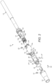
- a mouthpiece 12 of a first embodiment is shown as part of an inhalation device which, in this first exemplary embodiment, comprises a smoking apparatus 10.
- the smoking apparatus 10 comprises a controller body 11 and the mouthpiece 12.
- a combustible tobacco rod 13 can be inserted into the controller body 11.
- the controller body 11 comprises a first (mouth) end 11a and, a second (rod) end 11b opposite to the first end.
- the first and second ends 11a, 11b are open and are in fluid communication with each other.
- the controller body 11 includes a connector 25 at the first end 11a thereof, and the mouthpiece 12 is removably attachable to the connector 25.
- the tobacco rod 13 is a single-use component which is received in an aperture in the second end 11b of the controller body 11.
- the tobacco rod 13 is inserted into the second end 11b of the controller body 11 and ignited.
- a user inhales through the mouthpiece 12 and smoke is drawn through the tobacco rod 13, through the controller body 11 and out of the mouthpiece 12 as the tobacco rod 13 is combusted.
- the remaining portion (stub) of the combusted tobacco rod 13 is discarded and a new tobacco rod 13 is inserted for each subsequent use of the apparatus 10.
- the controller body 11 is a multi-use component of the apparatus 10, that is, it can be used for the smoking of multiple tobacco rods 13.
- the mouthpiece 12 is also a multi-use component although can be removed from the controller body 11 and replaced with a new mouthpiece 12 when required.
- the controller body 11 comprises a generally cylindrical housing 14 containing a ventilation control sleeve 15 rotatably mounted therein.
- the cylindrical housing 14 comprises a first portion 14a and a second portion 14b of a smaller diameter than the first portion 14a, extending from one end of the first portion 14a.
- the first portion 14a transitions to the second portion at an annular wall 16 which lies in a plane perpendicular to the central axis of the cylindrical housing 14.
- An end of a tobacco rod 13 to be smoked is held as a friction fit within the bore of the second portion 14b when the tobacco rod 13 is fully inserted into the controller body 11.
- a control ring 17 is rotatably mounted within the first portion 14a of the housing 14 and includes a plate 18 extending in an axial direction from a section of the perimeter of the control ring 17.
- the plate 18 is received within a correspondingly shaped slot 15a in the side wall of the ventilation control sleeve 15 such that rotation of the ventilation control sleeve 15 causes the control ring 17 to rotate.
- the control ring 17 abuts against the inside of the annular wall 16 of the housing 14, but includes a section of reduced thickness 19 around a portion of the circumference thereof which is spaced from the annular wall 16.
- a coil spring 20 is disposed within the cylindrical housing 14 between the control ring 17 and an inner rim 15b of the ventilation control sleeve 15. The spring 20 biases the control ring 17 against the annular wall 16 of the housing 14.
- the annular wall 16 of the cylindrical housing 14 includes a plurality of ventilation holes 21. Ventilation channels 22 are formed in the second portion 14b of the cylindrical housing 14 and extend from the ventilation holes 21 to the end of the second portion 14b.
- the cylindrical housing 14 also includes a plurality of air inlet slots (not shown) formed through the outer wall of the first portion 14a.
- the ventilation control sleeve 15 is rotatably secured within the housing 14 by a locking pin 23 extending through the wall of the housing 14 and locating in a slot 24 formed through a portion of the circumference of the ventilation control sleeve 15.
- the ventilation control sleeve 15 is thereby able to rotate over a range of movement determined by the length of the slot 24.
- the slot 24 includes detents 24a to define stable rotational positions of the ventilation control sleeve 15.
- a hollow cylindrical connector 25 is secured around the second portion 14b of the cylindrical housing 14 with an o-ring seal 26 disposed between the connector 25 and outside of the annular wall 16 of the cylindrical housing 14.
- the connector 25 is secured in place by a pair of retaining pins 27 which locate in a peripheral groove 28 in the second portion 14b of the cylindrical housing 14.
- the end of the connector 25 remote from the cylindrical housing 14 includes a projecting portion 29 of reduced diameter with a cam groove 30 formed around a section of the perimeter surface thereof.
- the mouthpiece 12 is connected to the connector 25 around the projecting portion 29 by a cam pin 31 extending through the mouthpiece wall and locating in the cam-groove 30, and an assembly pin 32 extending through the mouthpiece wall and locating in a channel 33 on the projecting portion 29 separate to the cam groove 30.
- An o-ring 34 may optionally be disposed between the mouthpiece 12 and connector 25 to form an airtight seal therebetween, although this is not essential and is omitted from Figures 3 - 14 .
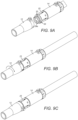
- the mouthpiece 12 is rotatable relative to the connector 25, as shown in Figures 9B and 9C , between flavour "OFF" and “ON” positions.
- the extent of rotation is defined by the length of the cam groove 30 in which the cam pin 31 travels as the mouthpiece 12 is rotated.
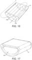
- the cam groove 30 is shown schematically in Figure 15 and comprises an "OFF" detent 30a and an “ON” detent 30b which provide stable positions of the mouthpiece 12 relative to the connector 25 in the respective flavour ON/OFF positions.
- Each detent 30a, 30b is spaced slightly further from an end face 29a of the projecting portion 29 than the remainder of the cam groove 30 so that the mouthpiece 12 is pulled tighter against the connector 25 when the cam pin 31 is located in the detents 30a, 30b than when the cam pin 31 is located in the rest of the cam groove 30 when rotating between ON/OFF positions. This promotes achieving an improved secure seal between the mouthpiece 12 and connector 25 in the ON/OFF positions.
- the detents 30a, 30b also provide a tactile feedback to the user that the mouthpiece 12 is correctly located in the desired position.
- the cam groove 30 also includes an entrance portion 30c which extends to the adjacent end face 29a of the projecting portion 29 of the connector 25 to receive the end of the cam pin 31 when the mouthpiece 12 is attached to and removed from the connector 25.
- the connector 25 is hollow to allow smoke to pass therethrough, and a path through the connector 25 exits through the end face 29a at a quadrant opening 43 at an upper portion thereof.
- a lower portion of the end face 29a includes a recess 44 which semi-circular and separate from the path through the connector 25.
- the recess 44 is a blind cavity, that is, it is closed-bottomed and open only at the end face 29a.
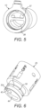
- the mouthpiece 12 is shown in more detail in Figures 3 - 5 , and includes a first open end 35 through which smoke is drawn by a user, and a second open end 36 which receives the projecting portion 29 of the connector 25.
- a passage 37 communicates the first and second open ends 35, 36.
- the passage 37 narrows from the first open end 35 to the second open end 36, such that the opening of the passage 37 at the second open end 36 is semi-circular and is disposed at the upper portion of the mouthpiece 12 only.
- the second open end 36 of the mouthpiece includes a recess 38 which is separate from the passage 37.
- the recess 38 is a blind cavity, that is, it includes an opening 39 at one end only, the opposite end being closed by an end wall 40.
- a body of organoleptic material 41 is disposed in the recess 38 to impart a flavour to smoke as the smoke stream passes over the body 41.
- the body 41 includes a cavity 42 extending therethrough.
- the body 41 may comprise a material matrix containing a flavourant, for example, cellulose acetate impregnated with menthol flavourant.
- the body 41 may comprise a different solid material impregnated with flavourant or other organoleptic compound.
- the flavourant imparted may be by means of particulate material entrained in the smoke stream, or in gaseous form evaporated or otherwise leached from the organoleptic material 41.
- the mouthpiece 12 In use, the mouthpiece 12 is pushed fully onto the connector 25 (see Figure 9A ) and the cam pin 31 enters the entrance portion 30c of the cam groove 30. The mouthpiece 12 is then rotated until the cam pin locates in the OFF detent 30a (see Figure 9B ).
- a user has the option of whether or not flavourant is added to the smoke stream passing through the device 10.
- the quadrant opening 43 in the connector 25 is aligned with the semi-circular second opening 36 in the mouthpiece 12 (see Figures 10A and 10B ) to define a first smoke flow path through the smoking device 10 in which the smoke steam passes straight from the connector 25 through the passage 37 in the mouthpiece 12 and out of the first open end 35 without encountering the body of flavourant material 41.
- the mouthpiece is rotated to the ON position (see Figure 9C ).
- the quadrant opening 43 in the connector 25 then partially overlaps the cavity 42 in the body of flavourant 41 (see Figure 12 ).
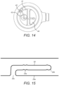
- the semi-circular recess 44 in the connector 25 also partially overlaps the cavity 42 in the body of flavourant material 41 (see Figure 14 ), and partially overlaps the semi-circular second opening 36 in the mouthpiece 12 (see Figures 11 and 14 ).
- smoke is drawn through a second smoke flow path through the smoking device 10, illustrated by arrow S in Figures 9 - 11 , which travels through the quadrant opening 43 into the cavity 42 in the organoleptic body 41, within which the smoke swirls and picks up flavourant as it sweeps over the surface of the body 41.
- the smoke stream S exits the cavity 42 into the semi-circular recess 44 in the connector 25 and passes from the semi-circular recess 44 into the second opening 36 in the mouthpiece 12, through the passage 37 and out of the mouthpiece through the first opening 35.
- the organoleptic body 41 may provide desirable flavour delivery for smoking of a predetermined number of tobacco rods 13, after which it may be depleted and require replacement. This may be achieved by removing the mouthpiece 12 and organoleptic body 41 and replacement with a new mouthpiece 12 having a fresh organoleptic body 41 therein. Alternatively, the organoleptic body 41 may be removable from the mouthpiece 12 and the user may replace the depleted organoleptic body 41 with a fresh one into the same mouthpiece 12. In the latter embodiment, the organoleptic body 41 may be provided within a sleeve or other outer casing (not shown) to facilitate removal from and replacement into the mouthpiece 12.
- the organoleptic body 41 may be formed with, or set into, the recess 38 in the mouthpiece as a manufacturing step, and the replacement mouthpiece 12 may be provided with a sealing cover over the opening 39 of the recess 38 to prevent escape of any organoleptic material before first use, such as any volatile and/or aromatic compounds.
- a cover could comprise a foil adhered over the opening 39 which a user would remove prior to connecting the new mouthpiece 12 to the connector 25.
- the replaceable component of either the organoleptic body 41 or mouthpiece 12 could be provided in multiple refill packs supplied separately to the controller body 11 of the smoking device 10, for example, multi-blister packs in which each replacement component is sealed within its own pocket.
- the detents 30a, 30b in the cam groove 30 are configured such that there is an interference fit between the mouthpiece 12 and connector 25 when the mouthpiece 12 is in the ON and OFF positions. When in the OFF position, this promotes an effective sealing between the recess 38 in the mouthpiece and the end face 29a of the projecting portion 29 of the connector 25, which ensures that none of the organoleptic compounds escape, such as volatile and/or aromatic compounds.
- the ventilation control sleeve 15 can be adjusted to control an amount of ambient air that is drawn into the smoking device 10 to mix with the smoke stream as a user draws on the mouthpiece 12.
- the control ring 17 covers the ventilation holes 21 in the annular wall 16 of the housing 14, and air that has entered the first portion 14a of the housing 14 through the air inlet slots is prevented from passing through the annular wall 16 and mixing with the smoke stream.
- the spring 20 biasing the control ring 17 into contact with the annular wall 16 ensures the seal is secure.
- Rotation of the ventilation control sleeve 15 to a second position moves the plate 18 and control ring 17 such that the section of reduced thickness 19 aligns with one of the ventilation holes 21 to provide a gap between the ventilation hole 21 and the control ring 17.
- Air that has entered the first portion 14a of the housing 14 through the air inlet slots is then able to pass through the annular wall 16 via the one exposed ventilation hole 21, pass along the corresponding ventilation channel 22, and mix with the smoke stream within the connector 25 as a mixing chamber, to provide a first degree of smoke ventilation and dilution.
- Ventilution control sleeve 15 Further rotation of the ventilation control sleeve 15 to a third position moves the plate 18 and control ring 17 such that the section of reduced thickness 19 aligns with more of the ventilation holes 21 to provide a gap between the additional ventilation holes 21 and the control ring 17. Air from the first portion 14a of the housing 14 is then able to pass through the annular wall 16 via the plurality of exposed ventilation holes 21, pass along the corresponding ventilation channels 22, and mix with the smoke stream within the connector 25, providing an increased level of smoke ventilation and dilution.
- the degree of external ventilation air that is introduced into the smoke stream is variable, thereby varying sensory intensity of the smoking experience.
- the smoke stream, with or without additional ventilation air passes over the organoleptic body 41 when smoke flavouring is selected by a user.
- control of the ventilation is independent to the control of additional flavour from the organoleptic body 41. This ensures a greater variety of user control over the smoking experience achievable from the smoking apparatus 10.
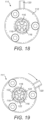
- Figure 16 shows a first alternative configuration of organoleptic body 41 useable with the mouthpiece 12 which comprises two passages 42a, 42b which are disposed side by side and which are open to a common space at the rear 45 of the organoleptic body 41.
- This common space may be formed within the organoleptic body 41 (i.e. the two cavities are connected) or the body 41 may not extend to the end wall 40 of the recess 38 so the common space is a rear area of the recess 38.
- the smoke stream S passes from the quadrant opening 43 into the first cavity 42a in the flavourant body 41, through the common space and out through the second cavity 42b into the semi-circular recess 44 in the connector 25 to the second opening 36 in the mouthpiece 12 and out thereof as described above.
- the smoke picks up flavourant as it sweeps over the inside surfaces of the first and second cavities 42a, 42b.
- Figure 17 shows a second alternative configuration of organoleptic body 41 useable with the mouthpiece 12, which comprises a single cavity 42c but which is larger than the cavity 42 of the first organoleptic body 41 described previously.
- the mouthpiece 12 including the second alternative configuration of organoleptic body would function in the same way as the first-described configuration, although the increased internal surface area of the cavity 42c may provide increased flavourant delivery.
- the embodiment of the mouthpiece 12 described above includes a cam pin 31 and assembly pin 32 to secure the mouthpiece 12 to the connector 25.
- an alternative embodiment may include inwardly projecting lugs on the inside wall of the mouthpiece in place of the cam and assembly pins.
- Such lugs could be moulded integrally with the mouthpiece 12, and the cam groove 30 and channel 33 in the connector 25 may both include a section extending to the end face 29a of the projecting portion 29.
- the mouthpiece could then be connected to and disconnected from the connector 25 by a bayonet-fitting type connection and so be simpler to operate by users.
- a flavourant delivery and control mechanism 111 of a smoking device (not shown) is shown for illustration purposes only.
- a mechanism can be incorporated into the connector 25 of the previously-described embodiment, and coupled to a mouthpiece of a different configuration, not having recess 38 but simply being a tubular element.
- the remaining features of the smoking device 10 of the first embodiment remain unchanged and so detailed description will not be repeated.
- the control mechanism 111 comprises a casing 112 having an inlet 113 in communication with an outlet 114 via a central chamber 115.
- the outlet 114 includes a plurality of blocking portions 116 arranged around the central axis of the outlet 114 which define a plurality of passages 117 therebetween.
- this arrangement is exemplary only and other numbers of passages/blocking portions may alternatively be provided.
- An actuator 118 is disposed in the casing 112 and has a cylindrical barrel portion 119 with a lever 120 extending therefrom.
- the lever extends through a slot (not shown) in the casing 112.
- the actuator 118 is rotatable within the casing 112 by movement of the lever 120 along the slot.
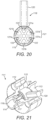
- the barrel 119 includes a plurality of sector-shaped passages 121 shaped corresponding to the blocking portions 116 and passages 117 in the outlet 114.
- the actuator 118 shown in Figures 18 - 21 includes six passages 121 although alternative embodiments may have more or less, depending on the configuration of the outlet 114.
- Alternating passages 121a of the actuator 118 include an organoleptic material 122 on an inside surface thereof, the remaining passages 121b do not have any such material.
- the passages 121a with the organoleptic material coating are aligned with the blocking portions 116 and the passages 121b without the organoleptic material coating are aligned with the passages 117 in the outlet 114. Therefore, the only fluid path through the control mechanism from the inlet 113 to the outlet 114 is through the passages 121b without the organoleptic material coating.
- a user of the smoking device 110 can select between unflavoured smoke or flavoured smoke by moving the lever 120 between the OFF and ON positions.
- the smoke stream passes through the passages 121b of the barrel 119 without encountering the organoleptic material.
- the smoke stream passes through the passages 121a of the barrel 119 which include the organoleptic material coating and so a flavourant is picked up by the smoke steam as it passes over the organoleptic material 122.
- the twist flavour control mechanism 111 of the second embodiment may be replaced after a predetermined number of smokes of tobacco rods 13 or when the flavour delivery reduces. Replacement may occur by replacement of the connector 25 on the housing 14.
- the control mechanism 111 may be provided on the mouthpiece instead of the connector, and so replacement of the flavour control mechanism may be effected by replacement of the mouthpiece as described previously.
- the connector would not need to have the flow path shaped as a quadrant 43 as described above, and could simply comprise a central circular aperture.
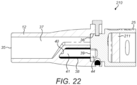
- a mouthpiece 12 and connector 25 of a smoking device 210 of a third embodiment is shown in Figure 22 and is similar to the mouthpiece 12 and smoking device 10 of the first embodiment, and like features retain the same reference numerals.
- the connector 25 of the third embodiment includes an additional filter element 211 in the form of a pad containing carbon-based material disposed in the main body of the connector 25 between the entrance to the quadrant opening 43 and the end of the second portion 14b of the housing 14.
- the smoking device 210 of the third embodiment is used in the same manner as the first embodiment described above, although the smoke stream passes through the filter element 211 as it travels from the housing 14 into the mouthpiece 12.
- the carbon material in the filter element 211 filters out further constituents of the smoke stream before it reaches the mouthpiece 12.
- the technical benefit described above of the mouthpiece making an effective seal against the connector 25 when in the flavour OFF position is again important so that the filter element 211 and the organoleptic body 41 are sealed from each other, in order to prevent any of the organoleptic material or volatile/aromatic components therefrom being absorbed by the carbon and therefore effectively wasted, reducing the life of the organoleptic body and/or reducing the effectiveness of the carbon-based filter element 211.
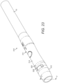
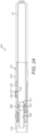
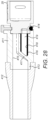
- FIGS 23 - 26 show a smoking device 310 for illustration purposes only comprising a controller body 311 configured to receive a combustible tobacco rod 13 as described previously.
- the controller body 311 comprises a housing 314 and a mouthpiece 312 attached to an end thereof opposite the tobacco rod 13 end.
- the housing 314 contains a holding tube 316 which is slidable within the housing 314 and is configured to receive the end of a tobacco rod 13.
- the holding tube 316 includes a pawl 317 which is receivable in an aperture 318 in the housing 314.
- a push button 319 is provided on the housing over the aperture 318 to push the pawl 317 out of engagement with the edge of the aperture 318 to allow the holding tube 316 to slide within the housing 314.
- a spring 320 is disposed within the housing against a first end of the holding tube 316 and biases the holding tube 316 in a direction out of the housing 314.
- the pawl 317 is configured to retain the holding tube 316 in a retracted position within the housing against the force of the spring 320.
- a duct 321 extends from the first end of the holding tube 316 and couples to a duct 322 in the housing 314 when the holding tube is in the retracted position (see Figure 24 ).
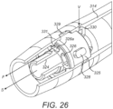
- a flavour control cartridge 323 is provided within the mouthpiece 312 and the end of the housing 314, and comprises a central conduit 324 and a rotatable collar 325 around the outside of the conduit 324.
- the conduit 324 is fluidly coupled to the duct 322 in the housing 314 and thereby to the duct 321 in the holding tube 316.
- the collar 325 includes a plurality of passages 326 extending in an axial direction through the collar 325.
- a blocking plate 327 is provided around a portion of the outer perimeter of the conduit 324 and is configured to block the flow path through one of the passages 326 when it is aligned with the blocking plate 327.
- An actuator button 328 projects from the outer surface of the collar 325 through a slot 329 in the side wall of the mouthpiece 312 such that the collar 325 can be rotated within the mouthpiece 312 between a first position and a second position by sliding the actuator button 328 along the slot 329.
- An outer wall of the mouthpiece 312 includes a ventilation hole 330 through which ambient air can pass into the area of the mouthpiece 312 behind the collar 325 of the flavour control cartridge 323 and around the outside of the conduit 324.
- An inside wall of one of the passages 326a includes a coating of an organoleptic material 331, which may comprise flavourant compound, such that as air flows through the coated passage 326a, flavourant is imparted to the airflow as it sweeps over the organoleptic material 331.
- an organoleptic material 331 which may comprise flavourant compound, such that as air flows through the coated passage 326a, flavourant is imparted to the airflow as it sweeps over the organoleptic material 331.
- a user uses the smoking device 310 to smoke a tobacco rod 13 with the collar 325 in the first position, when the user draws on the mouthpiece 312, smoke is drawn through the tobacco rod 13, through the duct 321 in the holding tube 316, through the duct 322 in the housing 314 and through the conduit 324 in the mouthpiece 312, as shown by arrow S in Figure 25 .
- ambient air is drawn through the ventilation hole 330, through the passages 326 in the collar 325 and into the mouthpiece 312, as shown by arrow V in Figure 25 , where the ventilation air V mixes with the smoke stream S.
- the coated passage 326a is aligned with the blocking plate 327, the ventilation airflow cannot pass therethrough and so no flavourant is imparted to the ventilation airflow.
- the configuration of the smoking device 310 of the fourth embodiment is such that the smoke stream S and the ventilation airflow V, F are kept separate and only mix in the final portion of the mouthpiece 312 just prior to delivery to the mouth. Furthermore, it is only the ventilation air V, which bypasses the smoke stream S, that encounters the organoleptic material 331, and so the various control surfaces of the ventilation and flavour control mechanism do not encounter the smoke stream S. This arrangement prevents build up of deposits from the smoke stream on the ventilation/flavour control surfaces, with the inherent hygiene benefits and improved mechanism longevity.
- the smoking device 310 of the fourth embodiment is described as having one coated passage 326a in the collar 325, variations to this configuration are intended, and the collar 325 may comprise a plurality of coated passages 326a.
- the flavour control cartridge 323 would include a corresponding plurality of blocking plates 327 such that all coated passages 326a are blocked in the collar's first position and are exposed for ventilation airflow to pass therethrough in the collar's second position.
- Such a configuration may be similar to the flavour control mechanism 111 of the second embodiment shown in Figures 18 - 21 .
- the a mechanism may be included to selectively open or close the ventilation hole 330 such that a user may select no ventilation air to be mixed with the smoke stream, as well as selecting whether the ventilation air is flavoured or not.
- Figures 27 and 28 show a connector 25, a mouthpiece 412 and a component 411 of a smoking device of a fifth embodiment.
- the smoking device of the fifth embodiment is largely similar to that of the first embodiment shown in Figures 1 - 15 and like features retain the same reference numerals, including the hollow cylindrical connector 25 shown in Figures 27 and 28 . Therefore, detailed description of identical components will not be repeated and are not shown again in subsequent figures.
- the mouthpiece 412 of the fifth embodiment is a simple hollow tube of tapering diameter and is not connected directly to the connector 25, and the mouthpiece 412 of the fifth embodiment does not include a blind cavity or contain any organoleptic material.
- An intermediate component 411 is connected to the connector 25 around the projecting portion 29 by a cam pin 31 locating in the cam-groove 30, in the same way that the mouthpiece 12 of the first embodiment is connected to the connector 25, and the component 411 is similarly rotatable relative to the connector 25 between flavour "OFF" and “ON” positions. It is this component 411 that provides the organoleptic/flavour additive to the smoke stream in the same way as that of the mouthpiece 12 of the first embodiment.
- the rotational operation of the component 411 on the connector 25 of the fifth embodiment is the same as that of the mouthpiece 12 of the first embodiment, including the cam groove detents which provide stable rotational positions, ensuring an effective seal between the component 411 and connector 25 in the ON/OFF positions and providing a tactile feedback to the user.
- the component 411 includes a first open end 413 which is connected to the mouthpiece 412 and through which smoke is drawn by a user, and a second open end 414 which receives the projecting portion 29 of the connector 25.
- a passage 415 communicates the first and second open ends 413, 414.
- the opening of the passage 415 is semi-circular at the second open end 414 and is disposed at the upper portion of the component 411 only.
- the second open end 414 includes a recess 416, separate from the passage 415, in the form of a blind cavity that is closed by an end wall 417.
- a body of organoleptic material 418 is disposed in the recess 416 to impart a flavour to smoke as the smoke stream passes over the body 418.
- the body 418 includes a cavity 419 extending therethrough.
- a user has the option of whether or not flavourant is added to the smoke stream passing through the device. This is controlled in the same way as the first embodiment except that the component 411 is rotated relative to the connector 25 instead of the mouthpiece 12 being rotated relative to the connector 25. Therefore, detailed description of the modes of operation and fluid flow paths will not be repeated.
- Replacement of the organoleptic body 418 when depleted after a predetermined number of tobacco rods 13 have been smoked may be achieved by removing the component 411 and replacement with a new component 411 having a fresh organoleptic body 418 therein.
- the organoleptic body 418 may be removable from the component 411 replaceable with a fresh one.
- the mouthpiece 412 may be replaceable along with, or independently of, the component 411, as and when the user may desire.
- the mouthpiece 412 may be a premium long-term component of the smoking device that is kept with the body 11, and only the intermediate component 411 is replaced regularly.
- the mouthpiece 412 may make a friction fit on the component 411, as shown in Figures 27 and 28 , or a cam pin/groove arrangement as between the component 411 and connector 25 may be provided.
- inhalation devices comprising smoking devices in which the inhalant comprises smoke generated from a combustible rod of smokeable material inserted into the body of the device.
- the present invention is not intended to be limited to smoking devices and may include other types of inhalation devices such as vapour-generating devices, such as electronic cigarettes, or other devices which produce an inhalant such as a gas, vapour or aerosol for inhalation by a user.
- Such devices may heat tobacco by a heat source without combustion of the tobacco, to cause a vapour to be produced from the tobacco for inhalation by a user.
- Such heat source may comprise an electrical heating element or heat produced by alternative means.
- such devices may heat liquid held in a reservoir, such as a nicotine solution, to produce an inhalant in the form of a gas or vapour.
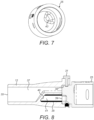
- a sixth embodiment of an inhalation device 501 which does not operate by combustion to tobacco is show in Figures 29 and 30 , and is similar to the first embodiment of figures 1 - 15 .
- the controller body 11 and mouthpiece 12 which function to provide ventilation and flavour control are the same and so a description thereof will not be repeated.
- the device 501 of the sixth embodiment is not configured to receive a combustible tobacco rod and is not designed for smoke from combustion of a tobacco rod to be drawn through the inhalation device.
- the sixth embodiment 501 comprises a device in which tobacco is heated by a heat source to cause constituents of the tobacco to be released in a vapour phase to be drawn through the device and inhaled by a user.
- a vapour-generating unit 502 is connected to the second end 11b of the body 11 and comprises a cylindrical component 503 having a chamber 504 containing tobacco 505, and electrical heating elements 506 surrounding the chamber 504 configured to heat the tobacco 505 in the chamber 504.
- a power supply such as a battery 507 is provided at one end of the component 503 to provide power to the heating elements 506 and may be detachable from the rest of the component 503 for separate recharging.
- An inlet orifice 508 is provided at one end of the component 503 in communication with the chamber 504 to allow air to be drawn into the chamber 504.
- An opposite end of the component 503 includes a connecting portion 509 configured to be received and retained within the second end 11b of the body 11.
- the chamber 504 is open at the connecting portion 509 so as to define a gas flow path through the inhalation device 501 when the vapour generating unit 502 is connected to the body 11, from the inlet orifice 508 to the mouthpiece 12. Therefore, air may be drawn into the chamber 504 via the inlet orifice 508, through the body 11 and the mouthpiece 12 when the user draws on the mouthpiece 12.
- a pressure sensor 510 is provided at the orifice 508 to detect when air is being drawn into the chamber 504 and the unit 502 is configured such that the heating elements 506 are powered when a reduced pressure is detected by the sensor 510 when air is being drawn into the chamber 504.
- a processor (not shown) may be provided in the component 503 to control operation of the heating elements 506 in response to signals from the pressure sensor 510.
- a user draws on the mouthpiece 12 which draws air though the inlet orifice 508 and into the chamber 504.
- the sensor 510 detects the reduced pressure at the inlet orifice 508 and the heating elements 506 are powered, heating the tobacco 505 and caused vapour phase products to be released from the tobacco 505.
- the released vapour is then drawn out of the chamber 504 through the connecting portion 509, through the body 11 and mouthpiece 12 and is inhaled by the user.
- the return to ambient pressure is detected by the sensor 510 and power to the heating elements 506 is stopped, stopping further heating of the tobacco until the user next draws on the mouthpiece.
- the inhalation device 501 of the sixth embodiment may choose to turn additional flavour on or off as described previously by rotation of the mouthpiece 12, and may also allow varying degrees of ambient external ventilation air into the vapour stream, to dilute and/or cool the vapour steam as desired, by rotation of the ventilation control sleeve 17 as described above.
- the unit 502 may be detached from the body by the ejection mechanism described above, or simply by being pulled out of the body, and replaced with a fresh unit.
- the component 503 portion of the vapour-generating unit 502 may be replaced with a new component 503 with a fresh full chamber 504 of tobacco 505, separately to replacement of the battery 507.
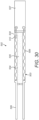
- a seventh embodiment of an inhalation device 601 which also does not operate by combustion to tobacco is show in figures 31 and 32 , and is similar to the sixth embodiment of figures 29 and 30 . Like features retain the same reference numerals and detailed description thereof will not be repeated. As with the sixth embodiment, the seventh embodiment is not configured to receive a combustible tobacco rod or for smoke from combustion of a tobacco rod to be drawn through the device. However, a difference between the seventh embodiment 601 and the sixth embodiment is that the device 601 of the seventh embodiment includes a different configuration of vapour-generating unit 602 connected to the second end 11b of the body 11.
- the vapour generating unit 602 comprises a cylindrical component 603 having a chamber 604 containing nicotine solution, and electrical heating elements 606 surrounding the chamber 604 configured to heat the solution in the chamber to produce nicotine vapour.
- a power supply such as a battery 607 is provided at one end of the component 603 to provide power to the heating elements 606 and may be detachable from the rest of the component 603 for separate recharging.
- An inlet orifice 608 is provided at one end of the component 603 in communication with the chamber 604 to allow air to be drawn into the chamber 604.
- the inlet orifice 608 may include a one-way valve 610.
- An opposite end of the component 603 includes a connecting portion 609 configured to be received and retained within the second end 11b of the body 11.
- the connecting portion 609 includes an open end and the chamber may include a one-way outlet valve 611 so that generated vapour may pass out of the chamber 604.
- a gas flow path can thereby be defined through the inhalation device 601 when the vapour generating unit 602 is connected to the body 11, from the inlet orifice 608 to the mouthpiece 12. Therefore, air may be drawn into the chamber 604 via the inlet orifice 608, through chamber 604, through the body 11 and the mouthpiece 12 when the user draws on the mouthpiece 12.
- a pressure sensor (not shown) may be provided at the orifice 608 to detect when air is being drawn into the chamber 604 and connected to a processor (not shown) to control the heating elements 606 to only be powered when a reduced pressure is detected by the sensor when air is being drawn into the chamber 604 by a user drawing on the mouthpiece.
- a user draws on the mouthpiece 12 which draws air though the inlet orifice 608 and into the chamber 604.
- the heating elements 606 are powered, heating the nicotine solution to generate nicotine vapour which is drawn out of the chamber 604 through the outlet valve 611, through the connecting portion 609, through the body 11 and mouthpiece 12 and is inhaled by the user.
- the user may choose to turn additional flavour on or off as described previously by rotation of the mouthpiece 12, and may also allow varying degrees of ambient external ventilation air into the vapour stream, to dilute and/or cool the vapour steam as desired, by rotation of the ventilation control sleeve 17 as described above.
- the unit 602 may be detached from the body by the ejection mechanism described above, or simply by being pulled out of the body, and replaced with a fresh unit.
- the component 603 with fresh full chamber 604 may be replaced separately to the battery.
- a flow path is described as extending from the inlet orifice 608, through the chamber 604 and through the connecting portion 609 into the body 11, it can be envisaged that ambient air may flow from the inlet orifice 608 into the component 603 but may flow within the component 603 in a passage that bypasses the chamber 604 and leads into the connecting portion 609.
- the chamber 604 may include a single outlet aperture, which may be provided with a one-way valve, through which vapour, generated by heating of the liquid within the chamber 604 by the heating elements 606, is expelled, to mix with the ambient air from the bypass passage, before being drawn through the body 11 of the inhalation device.
- the inhalant-generating components are described as being removeably received in the body 11 of the inhalant device.
- such inhalant-generating components may alternatively be formed integrally with the body and the entire device/apparatus may be discarded after use or once the inhalant-generating component is exhausted.
- inhalant may include smoke, aerosols, vapours or gases suitable for inhalation by a user.
- flavour and “flavourant” refer to materials which, where local regulations permit, may be used to create a desired taste or aroma in a product for adult consumers. They may include extracts (e.g., liquorice, hydrangea, Japanese white bark magnolia leaf, chamomile, fenugreek, clove, menthol, Japanese mint, aniseed, cinnamon, herb, wintergreen, cherry, berry, peach, apple, Drambuie, bourbon, scotch, whiskey, spearmint, peppermint, lavender, cardamom, celery, cascarilla, nutmeg, sandalwood, bergamot, geranium, honey essence, rose oil, vanilla, lemon oil, orange oil, cassia, caraway, cognac, jasmine, ylang-ylang, sage, fennel, piment, ginger, anise, coriander, coffee, or a mint oil from any species of the genus Mentha), flavour
Description
- In this specification is described an inhalation device and a component for such a device.
- Inhalation devices are known and include a variety of configurations, including devices for producing a vapour for inhalation by a user such as electronic cigarettes, and aerosol generating devices which produce a vapour or aerosol for inhalation by a user by heating a source material. Also, cigarette holders are known which comprise a body configured to receive a cigarette and through which the cigarette may be smoked. Such devices may include a filter material impregnated with a flavourant such that gas, vapour, aerosol or smoke drawn through the filter picks up the flavour.
EP 1859694 A1 discloses a component for an inhalation device according to the preamble ofclaim 1, namely a a filter holder configured to receive a cigarette and which includes a chamber for receiving a flavour generation element. - In this specification there are described embodiments of a component for an inhalation device, comprising a first end for connection to a body of an inhalation device and a second end, a passage extending through the component from the first end to the second end for the flow of inhalant therethrough, wherein the first end includes a blind cavity, separate to the passage and containing an organoleptic material.
- The organoleptic material includes at least one open hollow space formed therein.
- A cam pin may extend inwardly from an inside wall of the component proximate the first end to locate in a corresponding cam groove in a body of an inhalation device to connect the component to the inhalation device.
- The organoleptic material may be provided within a casing within the blind cavity of the component.
- The organoleptic material may be removable from the component to enable replacement with another portion of organoleptic material.
- The component may further comprise a removable cover sealed over the blind cavity to seal the organoleptic material from ambient atmosphere prior to use.
- In this specification there are also described embodiments of an inhalation device comprising a body with a first end configured to receive an additional component of the inhalation device and, a second end configured to receive an inhalant-generating component, a conduit extending through the body between the first and second ends, and a component as described above connected to the first end of the body.
- The component may be positionable relative to the body in a first position wherein the conduit is in fluid communication with the passage via the blind cavity to define a first inhalant flow path through the inhalation device in which an organoleptic additive may be introduced into the inhalant stream.
- The first inhalant flow path may extend through the open hollow space in the organoleptic material.
- The component may be moveable relative to the body between the first position and a second position in which the conduit is in fluid communication with the passage to define a second inhalant flow path through the inhalation device, and in which the blind cavity is sealed from the conduit and the passage to prevent introduction of an organoleptic additive into the inhalant stream.
- The second inhalant flow path may bypass the organoleptic material.
- Inhalant passing along the first inhalant flow path may sweep over the surface of the organoleptic material as it flows within the blind cavity when the component is in the first position.
- The component may be rotatable relative to the body between the first and second positions.
- The first end of the body may include a cam groove along which the cam pin travels as the component is rotated between the first and second positions.
- The cam groove may include a detent into which the cam pin can locate to provide a stable rotational position of the component relative to the body when in at least one of the first and second positions.
- The cam groove may be configured such that the component is urged into tighter engagement with the body when the cam pin locates in the detent than when the cam pin is located in the remainder of the cam groove.
- The cam groove may comprise a detent corresponding to each of the first and second rotational positions of the component.
- The cam groove may include a portion that is open to the first end of the body to allow the component to be connected to, and disconnected from the body.
- The first end of the body may include an end face through which the conduit extends, and the end face may further include a recess, wherein the recess in the end face fluidly communicates the blind cavity in the component with the passage in the component, when the component is in the first position.
- The first end of the body may include an end face through which the conduit extends, the end face further including a recess, wherein the blind cavity in the component fluidly communicates the conduit with the recess in the end face, when the component is in the first position.
- The conduit may be in fluid communication with the passage via the at least one open hollow space in the organoleptic material when the component is in the first position.
- The inhalation device may further comprise a carbon-based filter element within the elongate body.
- The filter element may be sealed from the organoleptic material when the component is in the second position.
- The inhalation device may comprise a ventilation control mechanism configured to selectively allow ambient air to be drawn into the body to mix with the inhalant stream.
- Control of the introduction of ambient air by the ventilation control mechanism may be independent of the selective introduction of an organoleptic additive into the inhalant stream.
- The component may comprise a mouthpiece of an inhalation device.
- In this specification there are also described examples for illustration purposes only of an inhalation device comprising a body with a first end configured to receive an inhalant-generating component, and a mouthpiece at an opposite end of the body, the body including a passage therethrough defining an inhalant flow path from the rod to the mouthpiece, and an inhalant modifying mechanism configured to selectively introduce an organoleptic additive to the inhalant prior to inhalation by a user, wherein the inhalant modifying mechanism comprises a control member having a plurality of apertures therethrough, at least one aperture loaded with an organoleptic material, and a blocking element, wherein the control member is moveable between a first position in which gas is permitted to flow through the at least one loaded aperture, and a second position in which the or each loaded aperture is closed by the blocking element so that gas is only permitted to flow through the remaining apertures, when a user draws on the mouthpiece.
- The control member may be disposed in the passage such that the inhalant flow path passes through the apertures in the control member.
- The control member may be disposed around the outside of the passage and the body may include a ventilation hole to allow ambient air to pass into the body, wherein the inhalant flow path bypasses the control member and ambient air drawn into the body passes through the apertures in the control member and mixes with the inhalant in the mouthpiece.
- The organoleptic material in the at least one aperture may be coated on an inside wall of the aperture such that gas flowing through the coated aperture sweeps over the organoleptic material for the additive to become entrained in the gas flow.
- In this specification there are also described embodiments of an inhalation device comprising a component comprising a passage extending therethrough and a blind cavity in a first end of the component, separate to the passage, a body having a first end configured for connection to the component, an opposite end configured to receive an inhalant-generating member, and a conduit extending through the body between the first and second ends, wherein the first end of the body includes a sealing face, wherein the component is rotatably connected to the body with the first end of the component in contact with the sealing face of the body, and wherein, in at least one position of the component relative to the body, the blind cavity is sealed closed by the sealing face of the body.
- The component may be rotatable relative to the body between a first position in which the conduit is in fluid communication with the passage via the blind cavity to define a first inhalant flow path through the smoking device, and a second position in which the conduit is in fluid communication with the passage to define a second inhalant flow path through the smoking device and in which the blind cavity is sealed closed by the sealing face of the body.
- The blind cavity may contain an organoleptic material.
- The inhalation device may include any feature or combination of features described above.
- In this specification there are also described embodiments of a pack of a plurality of components as described above. The pack may be hermetically sealed, and each component may be individually hermetically sealed from the remaining component(s). The components may comprise mouthpieces for an inhalation device.
- In this specification there are also described embodiments of an inhalation device comprising a smoking device configured to receive a rod of smokeable material to generate smoke as the inhalant to be drawn through the device by combustion of the tobacco rod.
- In this specification there are also described embodiments of an inhalation device configured to receive a vapour generating component comprising tobacco and a heat generator for heating the tobacco without combustion, to generate inhalant vapour to be drawn through the device.
- In this specification there are also described embodiments of an inhalation device configured to receive a vapour generating component comprising a reservoir of liquid and a heat generator for heating the liquid to generate inhalant vapour.
- The inhalation devices described above may be formed integrally with an inhalant-generating component as described above, or may be configured to removeably receive an inhalant-generating component.
- Embodiments of an inhalation device and a component for an inhalation device will now be described, by way of example only, with reference to the accompanying drawings, in which:
-
Figure 1 shows a perspective view of an inhalation device incorporating a mouthpiece of a first embodiment; -
Figure 2 shows an exploded perspective view of the inhalation device ofFigure 1 ; -
Figure 3 shows a perspective view of the mouthpiece and connector of the inhalation device ofFigure 1 ; -
Figure 4 shows an exploded perspective view of the mouthpiece and connector ofFigure 3 ; -
Figure 5 shows a rear perspective view of the mouthpiece ofFigures 1 - 4 ; -
Figure 6 shows a front perspective view of a connector of the smoking device ofFigures 1 and2 ; -
Figure 7 shows a rear perspective view of the connector ofFigure 6 ; -
Figure 8 shows a cross-sectional view along the line X-X of the mouthpiece and connector ofFigure 3 ; -
Figure 9A shows a perspective view of the inhalation device ofFigures 1 and2 , showing the mouthpiece prior to being secured onto the connector; -
Figures 9B and 9C show perspective views of the mouthpiece in the 'flavour off and 'flavour on' positions, respectively; -
Figures 10A and 10B show perspective and end views of the inhalation device ofFigures 1 and2 with the mouthpiece in the 'flavour off position; -
Figures 11A and 11B show perspective and end views of the inhalation device ofFigures 1 and2 with the mouthpiece in the 'flavour on' position; -
Figure 12 shows a rear perspective view of the connector and mouthpiece in the 'flavour on' position illustrating the flow path therethrough; -
Figure 13 shows a front perspective view of the connector and mouthpiece in the 'flavour on' position illustrating the flow path therethrough, with the mouthpiece shown as transparent for ease of illustration; -
Figure 14 shows front view of the connector and mouthpiece in the 'flavour on' position illustrating the flow path therethrough, with the mouthpiece shown as transparent for ease of illustration; -
Figure 15 shows a schematic two-dimensional view of the cam groove of the connector of the inhalation device ofFigure 1 ; -
Figure 16 shows a first alternative configuration of organoleptic body of the mouthpiece; -
Figure 17 shows a second alternative configuration of organoleptic body of the mouthpiece; -
Figure 18 , an example for illustration purposes only, shows an end view of a control mechanism of an inhalation device of a second embodiment in a 'flavour off position; -
Figure 19 , an example for illustration purposes only, shows an end view of the control mechanism ofFigure 18 in a 'flavour on' position; -
Figure 20 , an example for illustration purposes only, shows an end view of a component of the control mechanism ofFigures 18 and 19 ; -
Figure 21 , an example for illustration purposes only, shows a partial cut-away perspective view of the control mechanism ofFigure 19 ; -
Figure 22 shows a cross-sectional view of a mouthpiece and connector similar to that shown inFigure 8 , but of a third embodiment; -
Figure 23 , an example for illustration purposes only, shows a perspective view of an inhalation device of a fourth embodiment; -
Figure 24 , an example for illustration purposes only, shows a cross-sectional side view of the inhalation device ofFigure 23 along the line Y-Y; -
Figure 25 , an example for illustration purposes only, shows a cut-away view of a portion of the inhalation device ofFigure 23 in a first position; -
Figure 26 , an example for illustration purposes only, shows a cut-away view of a portion of the inhalation device ofFigure 23 in a second position; -
Figure 27 shows an exploded perspective view of a part of an inhalation device including a connector, a mouthpiece and a component of a fifth embodiment; -
Figure 28 shows a cross-sectional side view of the connector, component and mouthpiece ofFigure 27 ; -
Figure 29 shows a perspective view of an inhalation device of a sixth embodiment; -
Figure 30 shows a cross-sectional view through the inhalant-generating unit of the inhalation device ofFigure 29 ; -
Figure 31 shows a perspective view of an inhalation device of a seventh embodiment; and -
Figure 32 shows a cross-sectional view through the inhalant-generating unit of the inhalation device ofFigure 31 . - Referring to
Figures 1 - 15 , amouthpiece 12 of a first embodiment is shown as part of an inhalation device which, in this first exemplary embodiment, comprises asmoking apparatus 10. Thesmoking apparatus 10 comprises acontroller body 11 and themouthpiece 12. Acombustible tobacco rod 13 can be inserted into thecontroller body 11. Thecontroller body 11 comprises a first (mouth)end 11a and, a second (rod)end 11b opposite to the first end. The first andsecond ends controller body 11 includes aconnector 25 at thefirst end 11a thereof, and themouthpiece 12 is removably attachable to theconnector 25. Thetobacco rod 13 is a single-use component which is received in an aperture in thesecond end 11b of thecontroller body 11. - In use, the
tobacco rod 13 is inserted into thesecond end 11b of thecontroller body 11 and ignited. A user inhales through themouthpiece 12 and smoke is drawn through thetobacco rod 13, through thecontroller body 11 and out of themouthpiece 12 as thetobacco rod 13 is combusted. When the user has finished smoking, the remaining portion (stub) of the combustedtobacco rod 13 is discarded and anew tobacco rod 13 is inserted for each subsequent use of theapparatus 10. - The
controller body 11 is a multi-use component of theapparatus 10, that is, it can be used for the smoking ofmultiple tobacco rods 13. Themouthpiece 12 is also a multi-use component although can be removed from thecontroller body 11 and replaced with anew mouthpiece 12 when required. - The
controller body 11 comprises a generallycylindrical housing 14 containing aventilation control sleeve 15 rotatably mounted therein. Thecylindrical housing 14 comprises afirst portion 14a and asecond portion 14b of a smaller diameter than thefirst portion 14a, extending from one end of thefirst portion 14a. Thefirst portion 14a transitions to the second portion at anannular wall 16 which lies in a plane perpendicular to the central axis of thecylindrical housing 14. An end of atobacco rod 13 to be smoked is held as a friction fit within the bore of thesecond portion 14b when thetobacco rod 13 is fully inserted into thecontroller body 11. - A control ring 17 is rotatably mounted within the
first portion 14a of thehousing 14 and includes aplate 18 extending in an axial direction from a section of the perimeter of the control ring 17. Theplate 18 is received within a correspondingly shapedslot 15a in the side wall of theventilation control sleeve 15 such that rotation of theventilation control sleeve 15 causes the control ring 17 to rotate. The control ring 17 abuts against the inside of theannular wall 16 of thehousing 14, but includes a section of reducedthickness 19 around a portion of the circumference thereof which is spaced from theannular wall 16. - A
coil spring 20 is disposed within thecylindrical housing 14 between the control ring 17 and aninner rim 15b of theventilation control sleeve 15. Thespring 20 biases the control ring 17 against theannular wall 16 of thehousing 14. - The
annular wall 16 of thecylindrical housing 14 includes a plurality of ventilation holes 21.Ventilation channels 22 are formed in thesecond portion 14b of thecylindrical housing 14 and extend from the ventilation holes 21 to the end of thesecond portion 14b. Thecylindrical housing 14 also includes a plurality of air inlet slots (not shown) formed through the outer wall of thefirst portion 14a. - The
ventilation control sleeve 15 is rotatably secured within thehousing 14 by a lockingpin 23 extending through the wall of thehousing 14 and locating in aslot 24 formed through a portion of the circumference of theventilation control sleeve 15. Theventilation control sleeve 15 is thereby able to rotate over a range of movement determined by the length of theslot 24. Theslot 24 includesdetents 24a to define stable rotational positions of theventilation control sleeve 15. - A hollow
cylindrical connector 25 is secured around thesecond portion 14b of thecylindrical housing 14 with an o-ring seal 26 disposed between theconnector 25 and outside of theannular wall 16 of thecylindrical housing 14. Theconnector 25 is secured in place by a pair of retainingpins 27 which locate in aperipheral groove 28 in thesecond portion 14b of thecylindrical housing 14. - The end of the
connector 25 remote from thecylindrical housing 14 includes a projectingportion 29 of reduced diameter with acam groove 30 formed around a section of the perimeter surface thereof. Themouthpiece 12 is connected to theconnector 25 around the projectingportion 29 by acam pin 31 extending through the mouthpiece wall and locating in the cam-groove 30, and anassembly pin 32 extending through the mouthpiece wall and locating in achannel 33 on the projectingportion 29 separate to thecam groove 30. An o-ring 34 may optionally be disposed between themouthpiece 12 andconnector 25 to form an airtight seal therebetween, although this is not essential and is omitted fromFigures 3 - 14 . Themouthpiece 12 is rotatable relative to theconnector 25, as shown inFigures 9B and 9C , between flavour "OFF" and "ON" positions. The extent of rotation is defined by the length of thecam groove 30 in which thecam pin 31 travels as themouthpiece 12 is rotated. Thecam groove 30 is shown schematically inFigure 15 and comprises an "OFF"detent 30a and an "ON"detent 30b which provide stable positions of themouthpiece 12 relative to theconnector 25 in the respective flavour ON/OFF positions. Eachdetent end face 29a of the projectingportion 29 than the remainder of thecam groove 30 so that themouthpiece 12 is pulled tighter against theconnector 25 when thecam pin 31 is located in thedetents cam pin 31 is located in the rest of thecam groove 30 when rotating between ON/OFF positions. This promotes achieving an improved secure seal between themouthpiece 12 andconnector 25 in the ON/OFF positions. Thedetents mouthpiece 12 is correctly located in the desired position. Thecam groove 30 also includes anentrance portion 30c which extends to theadjacent end face 29a of the projectingportion 29 of theconnector 25 to receive the end of thecam pin 31 when themouthpiece 12 is attached to and removed from theconnector 25. - The
connector 25 is hollow to allow smoke to pass therethrough, and a path through theconnector 25 exits through theend face 29a at aquadrant opening 43 at an upper portion thereof. A lower portion of theend face 29a includes arecess 44 which semi-circular and separate from the path through theconnector 25. Therecess 44 is a blind cavity, that is, it is closed-bottomed and open only at theend face 29a. - The
mouthpiece 12 is shown in more detail inFigures 3 - 5 , and includes a firstopen end 35 through which smoke is drawn by a user, and a secondopen end 36 which receives the projectingportion 29 of theconnector 25. Apassage 37 communicates the first and second open ends 35, 36. Thepassage 37 narrows from the firstopen end 35 to the secondopen end 36, such that the opening of thepassage 37 at the secondopen end 36 is semi-circular and is disposed at the upper portion of themouthpiece 12 only. The secondopen end 36 of the mouthpiece includes arecess 38 which is separate from thepassage 37. Therecess 38 is a blind cavity, that is, it includes anopening 39 at one end only, the opposite end being closed by anend wall 40. - A body of
organoleptic material 41 is disposed in therecess 38 to impart a flavour to smoke as the smoke stream passes over thebody 41. Thebody 41 includes acavity 42 extending therethrough. Thebody 41 may comprise a material matrix containing a flavourant, for example, cellulose acetate impregnated with menthol flavourant. Alternatively, thebody 41 may comprise a different solid material impregnated with flavourant or other organoleptic compound. The flavourant imparted may be by means of particulate material entrained in the smoke stream, or in gaseous form evaporated or otherwise leached from theorganoleptic material 41. - In use, the
mouthpiece 12 is pushed fully onto the connector 25 (seeFigure 9A ) and thecam pin 31 enters theentrance portion 30c of thecam groove 30. Themouthpiece 12 is then rotated until the cam pin locates in theOFF detent 30a (seeFigure 9B ). When thesmoking device 10 is in use, a user has the option of whether or not flavourant is added to the smoke stream passing through thedevice 10. When themouthpiece 12 is in the OFF position, thequadrant opening 43 in theconnector 25 is aligned with the semi-circularsecond opening 36 in the mouthpiece 12 (seeFigures 10A and 10B ) to define a first smoke flow path through thesmoking device 10 in which the smoke steam passes straight from theconnector 25 through thepassage 37 in themouthpiece 12 and out of the firstopen end 35 without encountering the body offlavourant material 41. - If a user wishes to experience a flavoured smoke, the mouthpiece is rotated to the ON position (see
Figure 9C ). Thequadrant opening 43 in theconnector 25 then partially overlaps thecavity 42 in the body of flavourant 41 (seeFigure 12 ). In addition, thesemi-circular recess 44 in theconnector 25 also partially overlaps thecavity 42 in the body of flavourant material 41 (seeFigure 14 ), and partially overlaps the semi-circularsecond opening 36 in the mouthpiece 12 (seeFigures 11 and14 ). When a user draws on themouthpiece 12, smoke is drawn through a second smoke flow path through thesmoking device 10, illustrated by arrow S inFigures 9 - 11 , which travels through thequadrant opening 43 into thecavity 42 in theorganoleptic body 41, within which the smoke swirls and picks up flavourant as it sweeps over the surface of thebody 41. The smoke stream S exits thecavity 42 into thesemi-circular recess 44 in theconnector 25 and passes from thesemi-circular recess 44 into thesecond opening 36 in themouthpiece 12, through thepassage 37 and out of the mouthpiece through thefirst opening 35. - The
organoleptic body 41 may provide desirable flavour delivery for smoking of a predetermined number oftobacco rods 13, after which it may be depleted and require replacement. This may be achieved by removing themouthpiece 12 andorganoleptic body 41 and replacement with anew mouthpiece 12 having a freshorganoleptic body 41 therein. Alternatively, theorganoleptic body 41 may be removable from themouthpiece 12 and the user may replace the depletedorganoleptic body 41 with a fresh one into thesame mouthpiece 12. In the latter embodiment, theorganoleptic body 41 may be provided within a sleeve or other outer casing (not shown) to facilitate removal from and replacement into themouthpiece 12. In the former embodiment, theorganoleptic body 41 may be formed with, or set into, therecess 38 in the mouthpiece as a manufacturing step, and thereplacement mouthpiece 12 may be provided with a sealing cover over the opening 39 of therecess 38 to prevent escape of any organoleptic material before first use, such as any volatile and/or aromatic compounds. Such a cover could comprise a foil adhered over theopening 39 which a user would remove prior to connecting thenew mouthpiece 12 to theconnector 25. In either case, the replaceable component of either theorganoleptic body 41 ormouthpiece 12 could be provided in multiple refill packs supplied separately to thecontroller body 11 of thesmoking device 10, for example, multi-blister packs in which each replacement component is sealed within its own pocket. - The
detents cam groove 30 are configured such that there is an interference fit between themouthpiece 12 andconnector 25 when themouthpiece 12 is in the ON and OFF positions. When in the OFF position, this promotes an effective sealing between therecess 38 in the mouthpiece and theend face 29a of the projectingportion 29 of theconnector 25, which ensures that none of the organoleptic compounds escape, such as volatile and/or aromatic compounds. - The
ventilation control sleeve 15 can be adjusted to control an amount of ambient air that is drawn into thesmoking device 10 to mix with the smoke stream as a user draws on themouthpiece 12. In a first position of theventilation control sleeve 15, the control ring 17 covers the ventilation holes 21 in theannular wall 16 of thehousing 14, and air that has entered thefirst portion 14a of thehousing 14 through the air inlet slots is prevented from passing through theannular wall 16 and mixing with the smoke stream. Thespring 20 biasing the control ring 17 into contact with theannular wall 16 ensures the seal is secure. - Rotation of the
ventilation control sleeve 15 to a second position moves theplate 18 and control ring 17 such that the section of reducedthickness 19 aligns with one of the ventilation holes 21 to provide a gap between theventilation hole 21 and the control ring 17. Air that has entered thefirst portion 14a of thehousing 14 through the air inlet slots is then able to pass through theannular wall 16 via the one exposedventilation hole 21, pass along thecorresponding ventilation channel 22, and mix with the smoke stream within theconnector 25 as a mixing chamber, to provide a first degree of smoke ventilation and dilution. - Further rotation of the
ventilation control sleeve 15 to a third position moves theplate 18 and control ring 17 such that the section of reducedthickness 19 aligns with more of the ventilation holes 21 to provide a gap between the additional ventilation holes 21 and the control ring 17. Air from thefirst portion 14a of thehousing 14 is then able to pass through theannular wall 16 via the plurality of exposed ventilation holes 21, pass along thecorresponding ventilation channels 22, and mix with the smoke stream within theconnector 25, providing an increased level of smoke ventilation and dilution. - It will be appreciated that in the
smoking device 10 described above, the degree of external ventilation air that is introduced into the smoke stream is variable, thereby varying sensory intensity of the smoking experience. In all cases, the smoke stream, with or without additional ventilation air, passes over theorganoleptic body 41 when smoke flavouring is selected by a user. It will also be appreciated that control of the ventilation is independent to the control of additional flavour from theorganoleptic body 41. This ensures a greater variety of user control over the smoking experience achievable from thesmoking apparatus 10. -
Figure 16 shows a first alternative configuration oforganoleptic body 41 useable with themouthpiece 12 which comprises twopassages organoleptic body 41. - This common space may be formed within the organoleptic body 41 (i.e. the two cavities are connected) or the
body 41 may not extend to theend wall 40 of therecess 38 so the common space is a rear area of therecess 38. In use with themouthpiece 12 as described above when in the "ON" position, the smoke stream S passes from thequadrant opening 43 into thefirst cavity 42a in theflavourant body 41, through the common space and out through thesecond cavity 42b into thesemi-circular recess 44 in theconnector 25 to thesecond opening 36 in themouthpiece 12 and out thereof as described above. Here, the smoke picks up flavourant as it sweeps over the inside surfaces of the first andsecond cavities -
Figure 17 shows a second alternative configuration oforganoleptic body 41 useable with themouthpiece 12, which comprises asingle cavity 42c but which is larger than thecavity 42 of the firstorganoleptic body 41 described previously. Themouthpiece 12 including the second alternative configuration of organoleptic body would function in the same way as the first-described configuration, although the increased internal surface area of thecavity 42c may provide increased flavourant delivery. - The embodiment of the
mouthpiece 12 described above includes acam pin 31 andassembly pin 32 to secure themouthpiece 12 to theconnector 25. However, an alternative embodiment may include inwardly projecting lugs on the inside wall of the mouthpiece in place of the cam and assembly pins. Such lugs could be moulded integrally with themouthpiece 12, and thecam groove 30 andchannel 33 in theconnector 25 may both include a section extending to theend face 29a of the projectingportion 29. The mouthpiece could then be connected to and disconnected from theconnector 25 by a bayonet-fitting type connection and so be simpler to operate by users. - Referring now to
Figures 18 - 21 , a flavourant delivery andcontrol mechanism 111 of a smoking device (not shown) is shown for illustration purposes only. Such a mechanism can be incorporated into theconnector 25 of the previously-described embodiment, and coupled to a mouthpiece of a different configuration, not havingrecess 38 but simply being a tubular element. The remaining features of thesmoking device 10 of the first embodiment remain unchanged and so detailed description will not be repeated. - The
control mechanism 111 comprises acasing 112 having aninlet 113 in communication with anoutlet 114 via acentral chamber 115. Theoutlet 114 includes a plurality of blockingportions 116 arranged around the central axis of theoutlet 114 which define a plurality ofpassages 117 therebetween. In the embodiment shown, there are three blockingportions 116 defining threepassages 117, each shaped as a sector of the circular outlet. However, this arrangement is exemplary only and other numbers of passages/blocking portions may alternatively be provided. - An
actuator 118 is disposed in thecasing 112 and has acylindrical barrel portion 119 with alever 120 extending therefrom. The lever extends through a slot (not shown) in thecasing 112. Theactuator 118 is rotatable within thecasing 112 by movement of thelever 120 along the slot. Thebarrel 119 includes a plurality of sector-shapedpassages 121 shaped corresponding to the blockingportions 116 andpassages 117 in theoutlet 114. Theactuator 118 shown inFigures 18 - 21 includes sixpassages 121 although alternative embodiments may have more or less, depending on the configuration of theoutlet 114. Alternatingpassages 121a of theactuator 118 include anorganoleptic material 122 on an inside surface thereof, the remainingpassages 121b do not have any such material. When thelever 120 is in an "OFF" position as shown inFigure 18 , thepassages 121a with the organoleptic material coating are aligned with the blockingportions 116 and thepassages 121b without the organoleptic material coating are aligned with thepassages 117 in theoutlet 114. Therefore, the only fluid path through the control mechanism from theinlet 113 to theoutlet 114 is through thepassages 121b without the organoleptic material coating. Conversely, when thelever 120 is in an "ON" position as shown inFigure 19 , thepassages 121a with the organoleptic material coating are aligned with thepassages 117 in theoutlet 114 and thepassages 121b without the organoleptic material coating are aligned with the blockingportions 116. Therefore, in the ON position, the only fluid path through the control mechanism from theinlet 113 to theoutlet 114 is through thepassages 121a with the organoleptic material coating. - In use, a user of the smoking device 110 can select between unflavoured smoke or flavoured smoke by moving the
lever 120 between the OFF and ON positions. In the OFF position, the smoke stream passes through thepassages 121b of thebarrel 119 without encountering the organoleptic material. However, in the ON position, the smoke stream passes through thepassages 121a of thebarrel 119 which include the organoleptic material coating and so a flavourant is picked up by the smoke steam as it passes over theorganoleptic material 122. - The twist
flavour control mechanism 111 of the second embodiment may be replaced after a predetermined number of smokes oftobacco rods 13 or when the flavour delivery reduces. Replacement may occur by replacement of theconnector 25 on thehousing 14. In an alternative configuration of the smoking device, thecontrol mechanism 111 may be provided on the mouthpiece instead of the connector, and so replacement of the flavour control mechanism may be effected by replacement of the mouthpiece as described previously. In such an alternative embodiment, the connector would not need to have the flow path shaped as aquadrant 43 as described above, and could simply comprise a central circular aperture. - A
mouthpiece 12 andconnector 25 of asmoking device 210 of a third embodiment is shown inFigure 22 and is similar to themouthpiece 12 andsmoking device 10 of the first embodiment, and like features retain the same reference numerals. One difference between the first and third embodiments is that theconnector 25 of the third embodiment includes anadditional filter element 211 in the form of a pad containing carbon-based material disposed in the main body of theconnector 25 between the entrance to thequadrant opening 43 and the end of thesecond portion 14b of thehousing 14. Thesmoking device 210 of the third embodiment is used in the same manner as the first embodiment described above, although the smoke stream passes through thefilter element 211 as it travels from thehousing 14 into themouthpiece 12. The carbon material in thefilter element 211 filters out further constituents of the smoke stream before it reaches themouthpiece 12. The technical benefit described above of the mouthpiece making an effective seal against theconnector 25 when in the flavour OFF position is again important so that thefilter element 211 and theorganoleptic body 41 are sealed from each other, in order to prevent any of the organoleptic material or volatile/aromatic components therefrom being absorbed by the carbon and therefore effectively wasted, reducing the life of the organoleptic body and/or reducing the effectiveness of the carbon-basedfilter element 211. -
Figures 23 - 26 show asmoking device 310 for illustration purposes only comprising acontroller body 311 configured to receive acombustible tobacco rod 13 as described previously. Thecontroller body 311 comprises ahousing 314 and amouthpiece 312 attached to an end thereof opposite thetobacco rod 13 end. Thehousing 314 contains a holdingtube 316 which is slidable within thehousing 314 and is configured to receive the end of atobacco rod 13. The holdingtube 316 includes apawl 317 which is receivable in anaperture 318 in thehousing 314. Apush button 319 is provided on the housing over theaperture 318 to push thepawl 317 out of engagement with the edge of theaperture 318 to allow the holdingtube 316 to slide within thehousing 314. Aspring 320 is disposed within the housing against a first end of the holdingtube 316 and biases the holdingtube 316 in a direction out of thehousing 314. Thepawl 317 is configured to retain the holdingtube 316 in a retracted position within the housing against the force of thespring 320. - A
duct 321 extends from the first end of the holdingtube 316 and couples to aduct 322 in thehousing 314 when the holding tube is in the retracted position (seeFigure 24 ). - A
flavour control cartridge 323 is provided within themouthpiece 312 and the end of thehousing 314, and comprises acentral conduit 324 and arotatable collar 325 around the outside of theconduit 324. Theconduit 324 is fluidly coupled to theduct 322 in thehousing 314 and thereby to theduct 321 in the holdingtube 316. Thecollar 325 includes a plurality ofpassages 326 extending in an axial direction through thecollar 325. A blockingplate 327 is provided around a portion of the outer perimeter of theconduit 324 and is configured to block the flow path through one of thepassages 326 when it is aligned with the blockingplate 327. - An
actuator button 328 projects from the outer surface of thecollar 325 through aslot 329 in the side wall of themouthpiece 312 such that thecollar 325 can be rotated within themouthpiece 312 between a first position and a second position by sliding theactuator button 328 along theslot 329. An outer wall of themouthpiece 312 includes aventilation hole 330 through which ambient air can pass into the area of themouthpiece 312 behind thecollar 325 of theflavour control cartridge 323 and around the outside of theconduit 324. - An inside wall of one of the
passages 326a includes a coating of anorganoleptic material 331, which may comprise flavourant compound, such that as air flows through thecoated passage 326a, flavourant is imparted to the airflow as it sweeps over theorganoleptic material 331. When thecollar 325 is in the first position as shown inFigure 25 , thecoated passage 326a with theorganoleptic material 331 is located behind the blockingplate 327 and so airflow through thecoated passage 326a is prevented. When thecollar 325 is in the second position as shown inFigure 26 , thecoated passage 326a is rotated away from the blockingplate 327 such that air may flow therethrough. - If a user uses the
smoking device 310 to smoke atobacco rod 13 with thecollar 325 in the first position, when the user draws on themouthpiece 312, smoke is drawn through thetobacco rod 13, through theduct 321 in the holdingtube 316, through theduct 322 in thehousing 314 and through theconduit 324 in themouthpiece 312, as shown by arrow S inFigure 25 . Simultaneously, ambient air is drawn through theventilation hole 330, through thepassages 326 in thecollar 325 and into themouthpiece 312, as shown by arrow V inFigure 25 , where the ventilation air V mixes with the smoke stream S. As thecoated passage 326a is aligned with the blockingplate 327, the ventilation airflow cannot pass therethrough and so no flavourant is imparted to the ventilation airflow. If, however, thecollar 325 is moved to the second position, smoke is drawn into themouthpiece 312 as described above, shown by arrow S inFigure 26 , but the ambient air drawn through theventilation hole 330 is able to pass through thecoated passage 326a since it has moved out of alignment with the blockingplate 327, and so the ventilation airflow V passes through thecoated passage 326a and flavourant is imparted to the ventilation airflow as it sweeps over theorganoleptic material 331, shown by arrow F inFigure 26 . Thereafter, the flavoured airflow F and smoke stream S mix in themouthpiece 312. - The configuration of the
smoking device 310 of the fourth embodiment is such that the smoke stream S and the ventilation airflow V, F are kept separate and only mix in the final portion of themouthpiece 312 just prior to delivery to the mouth. Furthermore, it is only the ventilation air V, which bypasses the smoke stream S, that encounters theorganoleptic material 331, and so the various control surfaces of the ventilation and flavour control mechanism do not encounter the smoke stream S. This arrangement prevents build up of deposits from the smoke stream on the ventilation/flavour control surfaces, with the inherent hygiene benefits and improved mechanism longevity. - Although the
smoking device 310 of the fourth embodiment is described as having one coatedpassage 326a in thecollar 325, variations to this configuration are intended, and thecollar 325 may comprise a plurality ofcoated passages 326a. In such a variation, theflavour control cartridge 323 would include a corresponding plurality of blockingplates 327 such that allcoated passages 326a are blocked in the collar's first position and are exposed for ventilation airflow to pass therethrough in the collar's second position. Such a configuration may be similar to theflavour control mechanism 111 of the second embodiment shown inFigures 18 - 21 . - It is intended in a further alternative variation of the
smoking device 310 of the fourth embodiment that the a mechanism may be included to selectively open or close theventilation hole 330 such that a user may select no ventilation air to be mixed with the smoke stream, as well as selecting whether the ventilation air is flavoured or not. -
Figures 27 and28 show aconnector 25, amouthpiece 412 and acomponent 411 of a smoking device of a fifth embodiment. The smoking device of the fifth embodiment is largely similar to that of the first embodiment shown inFigures 1 - 15 and like features retain the same reference numerals, including the hollowcylindrical connector 25 shown inFigures 27 and28 . Therefore, detailed description of identical components will not be repeated and are not shown again in subsequent figures. - One difference between the smoking device of the fifth embodiment and that of the first embodiment is that the
mouthpiece 412 of the fifth embodiment is a simple hollow tube of tapering diameter and is not connected directly to theconnector 25, and themouthpiece 412 of the fifth embodiment does not include a blind cavity or contain any organoleptic material. - An
intermediate component 411 is connected to theconnector 25 around the projectingportion 29 by acam pin 31 locating in the cam-groove 30, in the same way that themouthpiece 12 of the first embodiment is connected to theconnector 25, and thecomponent 411 is similarly rotatable relative to theconnector 25 between flavour "OFF" and "ON" positions. It is thiscomponent 411 that provides the organoleptic/flavour additive to the smoke stream in the same way as that of themouthpiece 12 of the first embodiment. The rotational operation of thecomponent 411 on theconnector 25 of the fifth embodiment is the same as that of themouthpiece 12 of the first embodiment, including the cam groove detents which provide stable rotational positions, ensuring an effective seal between thecomponent 411 andconnector 25 in the ON/OFF positions and providing a tactile feedback to the user. - The
component 411 includes a firstopen end 413 which is connected to themouthpiece 412 and through which smoke is drawn by a user, and a secondopen end 414 which receives the projectingportion 29 of theconnector 25. Apassage 415 communicates the first and second open ends 413, 414. The opening of thepassage 415 is semi-circular at the secondopen end 414 and is disposed at the upper portion of thecomponent 411 only. The secondopen end 414 includes arecess 416, separate from thepassage 415, in the form of a blind cavity that is closed by anend wall 417. - A body of
organoleptic material 418 is disposed in therecess 416 to impart a flavour to smoke as the smoke stream passes over thebody 418. Thebody 418 includes acavity 419 extending therethrough. - In use of the smoking device of the fifth embodiment, a user has the option of whether or not flavourant is added to the smoke stream passing through the device. This is controlled in the same way as the first embodiment except that the
component 411 is rotated relative to theconnector 25 instead of themouthpiece 12 being rotated relative to theconnector 25. Therefore, detailed description of the modes of operation and fluid flow paths will not be repeated. - Replacement of the
organoleptic body 418 when depleted after a predetermined number oftobacco rods 13 have been smoked may be achieved by removing thecomponent 411 and replacement with anew component 411 having a freshorganoleptic body 418 therein. Alternatively, theorganoleptic body 418 may be removable from thecomponent 411 replaceable with a fresh one. - The
mouthpiece 412 may be replaceable along with, or independently of, thecomponent 411, as and when the user may desire. Alternatively, themouthpiece 412 may be a premium long-term component of the smoking device that is kept with thebody 11, and only theintermediate component 411 is replaced regularly. Themouthpiece 412 may make a friction fit on thecomponent 411, as shown inFigures 27 and28 , or a cam pin/groove arrangement as between thecomponent 411 andconnector 25 may be provided. - The above-described embodiments comprise inhalation devices comprising smoking devices in which the inhalant comprises smoke generated from a combustible rod of smokeable material inserted into the body of the device. However, the present invention is not intended to be limited to smoking devices and may include other types of inhalation devices such as vapour-generating devices, such as electronic cigarettes, or other devices which produce an inhalant such as a gas, vapour or aerosol for inhalation by a user. Such devices may heat tobacco by a heat source without combustion of the tobacco, to cause a vapour to be produced from the tobacco for inhalation by a user. Such heat source may comprise an electrical heating element or heat produced by alternative means. Alternatively, such devices may heat liquid held in a reservoir, such as a nicotine solution, to produce an inhalant in the form of a gas or vapour.
- A sixth embodiment of an
inhalation device 501 which does not operate by combustion to tobacco is show inFigures 29 and30 , and is similar to the first embodiment offigures 1 - 15 . Features of thecontroller body 11 andmouthpiece 12 which function to provide ventilation and flavour control are the same and so a description thereof will not be repeated. However, a difference between thesixth embodiment 501 and the first embodiment is that thedevice 501 of the sixth embodiment is not configured to receive a combustible tobacco rod and is not designed for smoke from combustion of a tobacco rod to be drawn through the inhalation device. Instead, thesixth embodiment 501 comprises a device in which tobacco is heated by a heat source to cause constituents of the tobacco to be released in a vapour phase to be drawn through the device and inhaled by a user. A vapour-generatingunit 502 is connected to thesecond end 11b of thebody 11 and comprises acylindrical component 503 having achamber 504 containingtobacco 505, andelectrical heating elements 506 surrounding thechamber 504 configured to heat thetobacco 505 in thechamber 504. A power supply such as abattery 507 is provided at one end of thecomponent 503 to provide power to theheating elements 506 and may be detachable from the rest of thecomponent 503 for separate recharging. - An
inlet orifice 508 is provided at one end of thecomponent 503 in communication with thechamber 504 to allow air to be drawn into thechamber 504. An opposite end of thecomponent 503 includes a connectingportion 509 configured to be received and retained within thesecond end 11b of thebody 11. Thechamber 504 is open at the connectingportion 509 so as to define a gas flow path through theinhalation device 501 when thevapour generating unit 502 is connected to thebody 11, from theinlet orifice 508 to themouthpiece 12. Therefore, air may be drawn into thechamber 504 via theinlet orifice 508, through thebody 11 and themouthpiece 12 when the user draws on themouthpiece 12. - A
pressure sensor 510 is provided at theorifice 508 to detect when air is being drawn into thechamber 504 and theunit 502 is configured such that theheating elements 506 are powered when a reduced pressure is detected by thesensor 510 when air is being drawn into thechamber 504. A processor (not shown) may be provided in thecomponent 503 to control operation of theheating elements 506 in response to signals from thepressure sensor 510. - In use, a user draws on the
mouthpiece 12 which draws air though theinlet orifice 508 and into thechamber 504. Thesensor 510 detects the reduced pressure at theinlet orifice 508 and theheating elements 506 are powered, heating thetobacco 505 and caused vapour phase products to be released from thetobacco 505. The released vapour is then drawn out of thechamber 504 through the connectingportion 509, through thebody 11 andmouthpiece 12 and is inhaled by the user. When the user stops drawing on the mouthpiece, the return to ambient pressure is detected by thesensor 510 and power to theheating elements 506 is stopped, stopping further heating of the tobacco until the user next draws on the mouthpiece. - As a user uses the
inhalation device 501 of the sixth embodiment, they may choose to turn additional flavour on or off as described previously by rotation of themouthpiece 12, and may also allow varying degrees of ambient external ventilation air into the vapour stream, to dilute and/or cool the vapour steam as desired, by rotation of the ventilation control sleeve 17 as described above. - Upon exhaustion of the
tobacco source 505 in the vapour-generatingunit 502, theunit 502 may be detached from the body by the ejection mechanism described above, or simply by being pulled out of the body, and replaced with a fresh unit. Thecomponent 503 portion of the vapour-generatingunit 502 may be replaced with anew component 503 with a freshfull chamber 504 oftobacco 505, separately to replacement of thebattery 507. - A seventh embodiment of an
inhalation device 601 which also does not operate by combustion to tobacco is show infigures 31 and32 , and is similar to the sixth embodiment offigures 29 and30 . Like features retain the same reference numerals and detailed description thereof will not be repeated. As with the sixth embodiment, the seventh embodiment is not configured to receive a combustible tobacco rod or for smoke from combustion of a tobacco rod to be drawn through the device. However, a difference between theseventh embodiment 601 and the sixth embodiment is that thedevice 601 of the seventh embodiment includes a different configuration of vapour-generatingunit 602 connected to thesecond end 11b of thebody 11. Here, thevapour generating unit 602 comprises acylindrical component 603 having achamber 604 containing nicotine solution, andelectrical heating elements 606 surrounding thechamber 604 configured to heat the solution in the chamber to produce nicotine vapour. A power supply such as abattery 607 is provided at one end of thecomponent 603 to provide power to theheating elements 606 and may be detachable from the rest of thecomponent 603 for separate recharging. - An
inlet orifice 608 is provided at one end of thecomponent 603 in communication with thechamber 604 to allow air to be drawn into thechamber 604. Theinlet orifice 608 may include a one-way valve 610. An opposite end of thecomponent 603 includes a connectingportion 609 configured to be received and retained within thesecond end 11b of thebody 11. The connectingportion 609 includes an open end and the chamber may include a one-way outlet valve 611 so that generated vapour may pass out of thechamber 604. A gas flow path can thereby be defined through theinhalation device 601 when thevapour generating unit 602 is connected to thebody 11, from theinlet orifice 608 to themouthpiece 12. Therefore, air may be drawn into thechamber 604 via theinlet orifice 608, throughchamber 604, through thebody 11 and themouthpiece 12 when the user draws on themouthpiece 12. - As with the sixth embodiment, a pressure sensor (not shown) may be provided at the
orifice 608 to detect when air is being drawn into thechamber 604 and connected to a processor (not shown) to control theheating elements 606 to only be powered when a reduced pressure is detected by the sensor when air is being drawn into thechamber 604 by a user drawing on the mouthpiece. - In use, a user draws on the
mouthpiece 12 which draws air though theinlet orifice 608 and into thechamber 604. Theheating elements 606 are powered, heating the nicotine solution to generate nicotine vapour which is drawn out of thechamber 604 through theoutlet valve 611, through the connectingportion 609, through thebody 11 andmouthpiece 12 and is inhaled by the user. - In use of the
inhalation device 601 of the seventh embodiment, the user may choose to turn additional flavour on or off as described previously by rotation of themouthpiece 12, and may also allow varying degrees of ambient external ventilation air into the vapour stream, to dilute and/or cool the vapour steam as desired, by rotation of the ventilation control sleeve 17 as described above. - Upon exhaustion of the nicotine solution supply in the vapour-generating
unit 602, theunit 602 may be detached from the body by the ejection mechanism described above, or simply by being pulled out of the body, and replaced with a fresh unit. Thecomponent 603 with freshfull chamber 604 may be replaced separately to the battery. - Although in the seventh embodiment, a flow path is described as extending from the
inlet orifice 608, through thechamber 604 and through the connectingportion 609 into thebody 11, it can be envisaged that ambient air may flow from theinlet orifice 608 into thecomponent 603 but may flow within thecomponent 603 in a passage that bypasses thechamber 604 and leads into the connectingportion 609. Thechamber 604 may include a single outlet aperture, which may be provided with a one-way valve, through which vapour, generated by heating of the liquid within thechamber 604 by theheating elements 606, is expelled, to mix with the ambient air from the bypass passage, before being drawn through thebody 11 of the inhalation device. - In the sixth and seventh embodiments described above, the inhalant-generating components are described as being removeably received in the
body 11 of the inhalant device. However, it is intended within the scope of the invention that such inhalant-generating components may alternatively be formed integrally with the body and the entire device/apparatus may be discarded after use or once the inhalant-generating component is exhausted. - As used herein, the term inhalant may include smoke, aerosols, vapours or gases suitable for inhalation by a user.
- As used herein, the terms "flavour" and "flavourant" refer to materials which, where local regulations permit, may be used to create a desired taste or aroma in a product for adult consumers. They may include extracts (e.g., liquorice, hydrangea, Japanese white bark magnolia leaf, chamomile, fenugreek, clove, menthol, Japanese mint, aniseed, cinnamon, herb, wintergreen, cherry, berry, peach, apple, Drambuie, bourbon, scotch, whiskey, spearmint, peppermint, lavender, cardamom, celery, cascarilla, nutmeg, sandalwood, bergamot, geranium, honey essence, rose oil, vanilla, lemon oil, orange oil, cassia, caraway, cognac, jasmine, ylang-ylang, sage, fennel, piment, ginger, anise, coriander, coffee, or a mint oil from any species of the genus Mentha), flavour enhancers, bitterness receptor site blockers, sensorial receptor site activators or stimulators, sugars and/or sugar substitutes (e.g., sucralose, acesulfame potassium, aspartame, saccharine, cyclamates, lactose, sucrose, glucose, fructose, sorbitol, or mannitol), and other additives such as charcoal, chlorophyll, minerals, botanicals, or breath freshening agents. They may be imitation, synthetic or natural ingredients or blends thereof. They may be in any suitable form, for example, oil, liquid, or powder In order to address various issues and advance the art, the entirety of this disclosure shows by way of illustration various embodiments in which the claimed invention(s) may be practiced and provide for superior inhalation device and component for an inhalation device. The advantages and features of the disclosure are of a representative sample of embodiments only, and are not exhaustive and/or exclusive. They are presented only to assist in understanding and teach the claimed features. It is to be understood that advantages, embodiments, examples, functions, features, structures, and/or other aspects of the disclosure are to be considered limitations on the disclosure as defined by the claims and that other embodiments may be utilised and modifications may be made without departing from the scope as defined by the claims.
Claims (14)
- A component for an inhalation device, comprising a first end for connection to a body of an inhalation device and a second end, a passage extending through the component from the first end to the second end for the flow of inhalant therethrough, characterised in that the first end includes a blind cavity (38), separate to the passage and containing an organoleptic material (41),
the organoleptic material (41) includes at least one open hollow space formed therein (42). - A component according to claim 1 wherein a cam pin (31) extends inwardly from an inside wall of the component proximate the first end to locate in a corresponding cam groove (30) in a body of a smoking device to connect the component to the smoking device.
- A component according to claim 1 or claim 2 wherein the organoleptic material (41) is provided within a casing within the blind cavity (38) of the component.
- A component according to any preceding claim wherein the organoleptic material (41) is removable from the component to enable replacement with another portion of organoleptic material.
- A component according to any preceding claim further comprising a removable cover sealed over the blind cavity (38) to seal the organoleptic material (41) from ambient atmosphere prior to use.
- An inhalation device comprising a body (11) with a first end configured to receive an additional component of the inhalation device and, a second end configured to receive an inhalant-generating component, a conduit extending through the body between the first and second ends, and a component according to any of claims 1 - 5 connected to the first end of the body.
- An inhalation device according to claim 6 wherein the component is positionable relative to the body (11) in a first position wherein the conduit is in fluid communication with the passage via the blind cavity to define a first inhalant flow path through the inhalation device in which an organoleptic additive may be introduced into the inhalant stream.
- An inhalation device according to claim 7 when dependent on claim 2, wherein the first inhalant flow path extends through the open hollow space (42) in the organoleptic material.
- An inhalation device according to claim 7 or claim 8 wherein the component is moveable relative to the body (11) between the first position and a second position in which the conduit is in fluid communication with the passage to define a second inhalant flow path through the inhalation device, and in which the blind cavity is sealed from the conduit and the passage to prevent introduction of an organoleptic additive into the inhalant stream.
- An inhalation device according to any of claims 7 - 9 comprising a ventilation control mechanism configured to selectively allow ambient air to be drawn into the body (11) to mix with the inhalant stream.
- A pack of a plurality of components according to any of claims 1 - 5.
- An inhalation device according to any of claims 6 to 10 comprising a smoking device configured to receive a rod (13) of smokeable material to generate smoke as the inhalant to be drawn through the device by combustion of the tobacco rod.
- An inhalation device according to any of claims 6 to 10 configured to receive a vapour generating component (503) comprising tobacco and a heat generator for heating the tobacco without combustion, to generate inhalant vapour to be drawn through the device.
- An inhalation device according to any of claims 6 - 10 configured to receive a vapour generating component (603) comprising a reservoir of liquid and a heat generator for heating the liquid to generate inhalant vapour.
Priority Applications (3)
| Application Number | Priority Date | Filing Date | Title |
|---|---|---|---|
| EP18214919.5A EP3491943B8 (en) | 2013-02-27 | 2014-02-24 | An inhalation device |
| EP20210790.0A EP3799726A1 (en) | 2013-02-27 | 2014-02-24 | An inhalation device and a component for an inhalation device |
| PL18214919T PL3491943T3 (en) | 2013-02-27 | 2014-02-24 | An inhalation device |
Applications Claiming Priority (2)
| Application Number | Priority Date | Filing Date | Title |
|---|---|---|---|
| GB1303437.6A GB2511305A (en) | 2013-02-27 | 2013-02-27 | A smoking device and a component for a smoking device |
| PCT/GB2014/050544 WO2014132044A2 (en) | 2013-02-27 | 2014-02-24 | An inhalation device and component for an inhalation device |
Related Child Applications (4)
| Application Number | Title | Priority Date | Filing Date |
|---|---|---|---|
| EP18214919.5A Division EP3491943B8 (en) | 2013-02-27 | 2014-02-24 | An inhalation device |
| EP18214919.5A Division-Into EP3491943B8 (en) | 2013-02-27 | 2014-02-24 | An inhalation device |
| EP20210790.0A Division EP3799726A1 (en) | 2013-02-27 | 2014-02-24 | An inhalation device and a component for an inhalation device |
| EP20210790.0A Division-Into EP3799726A1 (en) | 2013-02-27 | 2014-02-24 | An inhalation device and a component for an inhalation device |
Publications (3)
| Publication Number | Publication Date |
|---|---|
| EP2961285A2 EP2961285A2 (en) | 2016-01-06 |
| EP2961285B1 EP2961285B1 (en) | 2019-01-02 |
| EP2961285B2 true EP2961285B2 (en) | 2023-11-29 |
Family
ID=48092149
Family Applications (3)
| Application Number | Title | Priority Date | Filing Date |
|---|---|---|---|
| EP14706694.8A Active EP2961285B2 (en) | 2013-02-27 | 2014-02-24 | An inhalation device and component for an inhalation device |
| EP18214919.5A Active EP3491943B8 (en) | 2013-02-27 | 2014-02-24 | An inhalation device |
| EP20210790.0A Pending EP3799726A1 (en) | 2013-02-27 | 2014-02-24 | An inhalation device and a component for an inhalation device |
Family Applications After (2)
| Application Number | Title | Priority Date | Filing Date |
|---|---|---|---|
| EP18214919.5A Active EP3491943B8 (en) | 2013-02-27 | 2014-02-24 | An inhalation device |
| EP20210790.0A Pending EP3799726A1 (en) | 2013-02-27 | 2014-02-24 | An inhalation device and a component for an inhalation device |
Country Status (10)
| Country | Link |
|---|---|
| US (2) | US10470491B2 (en) |
| EP (3) | EP2961285B2 (en) |
| JP (1) | JP6211630B2 (en) |
| CN (1) | CN105120694B (en) |
| ES (1) | ES2856332T3 (en) |
| GB (1) | GB2511305A (en) |
| HU (1) | HUE054470T2 (en) |
| PL (1) | PL3491943T3 (en) |
| RU (1) | RU2626933C2 (en) |
| WO (1) | WO2014132044A2 (en) |
Families Citing this family (44)
| Publication number | Priority date | Publication date | Assignee | Title |
|---|---|---|---|---|
| GB2511303A (en) | 2013-02-27 | 2014-09-03 | British American Tobacco Co | Smoking apparatus |
| GB2511305A (en) | 2013-02-27 | 2014-09-03 | British American Tobacco Co | A smoking device and a component for a smoking device |
| WO2015009863A1 (en) * | 2013-07-19 | 2015-01-22 | Altria Client Services Inc. | Electronic smoking article |
| USD799747S1 (en) * | 2015-01-21 | 2017-10-10 | Champion Southwest Enterprises, LLC | Mouthpiece for an electronic cigarette |
| EA034488B1 (en) | 2015-05-06 | 2020-02-13 | Олтриа Клайент Сервисиз Ллк | Non-combustible smoking device |
| CN104886782B (en) * | 2015-05-25 | 2018-02-06 | 林光榕 | Electronic cigarette suction nozzle and its manufacture method |
| US10398169B2 (en) | 2015-06-25 | 2019-09-03 | Altria Client Services Llc | E-vapor device including at least one of a bayonet connector and a connector with a knurled pattern for forming a welded junction |
| KR20170047786A (en) * | 2015-10-23 | 2017-05-08 | 김의석 | Apparatus for inhailing aromas |
| PL3167728T3 (en) * | 2015-11-12 | 2020-10-05 | Fontem Holdings 1 B.V. | Electronic smoking device with cavity for liquid reservoir |
| US10314334B2 (en) | 2015-12-10 | 2019-06-11 | R.J. Reynolds Tobacco Company | Smoking article |
| US11744296B2 (en) | 2015-12-10 | 2023-09-05 | R. J. Reynolds Tobacco Company | Smoking article |
| GB201602831D0 (en) * | 2016-02-18 | 2016-04-06 | British American Tobacco Co | Flavour delivery device |
| WO2017214884A1 (en) * | 2016-06-15 | 2017-12-21 | 孟令红 | Electronic cigarette |
| CN207040892U (en) * | 2016-07-23 | 2018-02-27 | 深圳市合元科技有限公司 | Baking formula smoking set |
| US11006661B2 (en) * | 2016-08-15 | 2021-05-18 | Mamood Valadi | Cigarette-like device for administration of substances |
| GB201615602D0 (en) | 2016-09-14 | 2016-10-26 | British American Tobacco Investments Ltd | Receptacle Section |
| GB201615601D0 (en) | 2016-09-14 | 2016-10-26 | British American Tobacco Investments Ltd | Receptacle section |
| US10842193B2 (en) | 2016-10-04 | 2020-11-24 | Altria Client Services Llc | Non-combustible smoking device and elements thereof |
| CN106376977B (en) * | 2016-10-18 | 2023-04-18 | 云南中烟工业有限责任公司 | Smoking set separate air inlet device |
| US10433585B2 (en) | 2016-12-28 | 2019-10-08 | Altria Client Services Llc | Non-combustible smoking systems, devices and elements thereof |
| GB201700136D0 (en) | 2017-01-05 | 2017-02-22 | British American Tobacco Investments Ltd | Aerosol generating device and article |
| GB201700620D0 (en) | 2017-01-13 | 2017-03-01 | British American Tobacco Investments Ltd | Aerosol generating device and article |
| GB201720338D0 (en) | 2017-12-06 | 2018-01-17 | British American Tobacco Investments Ltd | Component for an aerosol-generating apparatus |
| US20190174824A1 (en) * | 2017-12-12 | 2019-06-13 | Bradley Aaron Neuhaus | Botanic Solid Vapor Generation Apparatus |
| US20190174825A1 (en) * | 2017-12-12 | 2019-06-13 | Bradley Aaron Neuhaus | Botanic Solid Vapor Generation Apparatus |
| US10786010B2 (en) | 2017-12-15 | 2020-09-29 | Rai Strategic Holdings, Inc. | Aerosol delivery device with multiple aerosol delivery pathways |
| US11033051B2 (en) | 2017-12-29 | 2021-06-15 | Altria Client Services Llc | Tip device for electronic vaping device |
| US11723399B2 (en) | 2018-07-13 | 2023-08-15 | R.J. Reynolds Tobacco Company | Smoking article with detachable cartridge |
| KR20210073595A (en) | 2018-11-08 | 2021-06-18 | 쥴 랩스, 인크. | Evaporator apparatus having more than one heating element |
| US11064727B2 (en) | 2019-02-06 | 2021-07-20 | Altria Client Services Llc | Sensor apparatuses and systems |
| EP3692835A1 (en) * | 2019-02-07 | 2020-08-12 | Nerudia Limited | Smoking substitute apparatus |
| EP3692836A1 (en) * | 2019-02-07 | 2020-08-12 | Nerudia Limited | Smoking substitute apparatus |
| EP3692840A1 (en) * | 2019-02-07 | 2020-08-12 | Nerudia Limited | Smoking substitute apparatus and smoking substitute kit |
| CN113660871B (en) * | 2019-04-29 | 2024-02-06 | 菲利普莫里斯生产公司 | Aerosol generating device with a removable attached mouthpiece |
| US11395510B2 (en) | 2019-07-19 | 2022-07-26 | R.J. Reynolds Tobacco Company | Aerosol delivery device with rotatable enclosure for cartridge |
| US11330838B2 (en) | 2019-07-19 | 2022-05-17 | R. J. Reynolds Tobacco Company | Holder for aerosol delivery device with detachable cartridge |
| US10813386B1 (en) * | 2019-08-29 | 2020-10-27 | Puff Corporation | Transportable mouthpiece |
| US11246343B2 (en) * | 2019-09-26 | 2022-02-15 | Tuanfang Liu | Electronic cigarette |
| US11589616B2 (en) | 2020-04-29 | 2023-02-28 | R.J. Reynolds Tobacco Company | Aerosol delivery device with sliding and axially rotating locking mechanism |
| US11439185B2 (en) | 2020-04-29 | 2022-09-13 | R. J. Reynolds Tobacco Company | Aerosol delivery device with sliding and transversely rotating locking mechanism |
| US11000067B1 (en) | 2020-10-05 | 2021-05-11 | Puff Corporation | Portable electronic vaporizing device |
| CN113068868B (en) * | 2021-03-24 | 2023-04-07 | 西安医学院 | Electronic flue gas sol filtering device |
| US11825872B2 (en) | 2021-04-02 | 2023-11-28 | R.J. Reynolds Tobacco Company | Aerosol delivery device with protective sleeve |
| CN114145497B (en) | 2021-12-14 | 2024-04-09 | 宁波依兰雅丝护肤品有限公司 | Leak protection liquid electron atomizer |
Citations (3)
| Publication number | Priority date | Publication date | Assignee | Title |
|---|---|---|---|---|
| US4484590A (en) † | 1982-02-01 | 1984-11-27 | Singh Prithvi P | Pipe with tobacco storage |
| US4677995A (en) † | 1986-02-24 | 1987-07-07 | Philip Morris Incorporated | Filter cigarette |
| WO2011095410A1 (en) † | 2010-02-05 | 2011-08-11 | Tobacco Research And Development Institute (Proprietary) Limited | Flow control device for a smoking article |
Family Cites Families (53)
| Publication number | Priority date | Publication date | Assignee | Title |
|---|---|---|---|---|
| US2153623A (en) | 1938-03-19 | 1939-04-11 | Louis J Jacobson | Cigarette holder |
| GB607728A (en) | 1946-01-29 | 1948-09-03 | Waldemar Lazare Colassi | Improvements in or relating to cigarette holders |
| US2956568A (en) * | 1956-09-18 | 1960-10-18 | Knudsen Magnus | Pipe for tobacco |
| US3339557A (en) | 1965-03-12 | 1967-09-05 | Lew W Karalus | Cigarette and smoke filter and flavor means |
| US3468316A (en) | 1965-11-15 | 1969-09-23 | Nixotene Corp | Tobacco smoke filter |
| US4038994A (en) | 1975-11-10 | 1977-08-02 | Aikman Leslie N | Tobacco smoke filter unit |
| DE2639820C3 (en) * | 1976-09-03 | 1980-06-26 | Wolfgang 8022 Gruenwald Seeger | Method and device for modifying commercial tobacco products |
| US4227540A (en) | 1978-06-23 | 1980-10-14 | Edison Robert G | Menthol filter for cigarettes |
| US4478228A (en) * | 1982-09-30 | 1984-10-23 | Chister Rene A | Tobacco smoking pipe |
| US4559955A (en) | 1983-06-20 | 1985-12-24 | Link Electronics Ltd | Controlled air bleed cigarette holder |
| US4637407A (en) | 1985-02-28 | 1987-01-20 | Cangro Industries, Inc. | Cigarette holder |
| EP0235736B1 (en) * | 1986-03-06 | 1991-05-15 | Carlo Lugli | Improved mouth-piece for filtering the smoke of cigarettes and the like |
| JP2566243B2 (en) | 1987-07-02 | 1996-12-25 | 能美防災株式会社 | Fire alarm |
| JPS649598U (en) * | 1987-07-04 | 1989-01-19 | ||
| JPH0198470A (en) * | 1987-10-09 | 1989-04-17 | Setsuo Kuroki | Filter of pipe type for intaking aromatic of tobacco smoke |
| US4848375A (en) | 1987-11-10 | 1989-07-18 | Philip Morris Incorporated | Filter cigarette |
| US5082008A (en) | 1988-12-09 | 1992-01-21 | Johnson Robert R | Smoking article |
| US4991605A (en) | 1989-04-24 | 1991-02-12 | Philip Morris Incorporated | Container for additive materials for smoking articles |
| US4945931A (en) | 1989-07-14 | 1990-08-07 | Brown & Williamson Tobacco Corporation | Simulated smoking device |
| UA26230A (en) * | 1990-03-02 | 1999-07-19 | Глексо Груп Лімітед | SHARED USER INHALATOR WITH TREATMENT UNIT AND TREATMENT UNIT |
| GB2299012B (en) * | 1995-03-21 | 1998-09-02 | Ian Gilbert Williams | Pendant disc pipe |
| CN2262810Y (en) | 1996-06-28 | 1997-09-24 | 黄齐备 | Health-care cigarette holder |
| DE19645563A1 (en) | 1996-11-05 | 1998-05-07 | Tabac Fab Reunies Sa | Holder for cigarette articles |
| US6336896B1 (en) | 1999-11-12 | 2002-01-08 | Chieh-Hsueh Hsu | Automatic filter tip attaching machine |
| PT1377184E (en) | 2001-02-22 | 2010-06-28 | Philip Morris Prod | Cigarette and filter with downstream flavor addition |
| EP1609376A1 (en) | 2003-04-01 | 2005-12-28 | Shusei Takano | Nicotine suction pipe and nicotine holder |
| US20040237974A1 (en) | 2003-05-05 | 2004-12-02 | Min Wang Wei | Filtering cigarette holder |
| EP1692054A1 (en) | 2003-11-18 | 2006-08-23 | Yansong Shan | Healthy pleasurable inhalation device |
| CN2686350Y (en) | 2004-02-13 | 2005-03-23 | 冯宇 | Soakage adjustable nozzle for nicotine inhalator |
| EP1859694B1 (en) * | 2005-03-17 | 2011-05-11 | Japan Tobacco, Inc. | Filter holder used for smoking, smoking pipe, and smoking pipe unit |
| DE102005016415A1 (en) | 2005-04-08 | 2006-11-02 | Nicstic Ag | Filter connection for smokeless cigarette, has heating peg interlocked to filter mouthpiece and fitted into nicotine deposit and acetate-made filter |
| US20060272659A1 (en) | 2005-06-06 | 2006-12-07 | Gerd Kobal | Modular smoking article and method of use |
| US7658197B1 (en) | 2005-07-18 | 2010-02-09 | Alvaro Villagomez | Smoking pipe with cleaning valve |
| US20070074733A1 (en) | 2005-10-04 | 2007-04-05 | Philip Morris Usa Inc. | Cigarettes having hollow fibers |
| DE602006011268D1 (en) * | 2006-02-20 | 2010-02-04 | Black & Decker Inc | Air flow control mechanism |
| NZ571453A (en) | 2006-03-28 | 2011-09-30 | Philip Morris Prod | Smoking article with a restrictor that reduces carbon monoxide but maintains a high resistance to draw |
| CN201067079Y (en) * | 2006-05-16 | 2008-06-04 | 韩力 | Simulation aerosol inhaler |
| EP1972215A1 (en) | 2007-03-20 | 2008-09-24 | Wedegree GmbH | Smoke-free cigarette substitute |
| CA2914382C (en) | 2007-08-10 | 2018-03-06 | Philip Morris Products S.A. | Distillation-based smoking article |
| CN201108029Y (en) | 2007-11-06 | 2008-09-03 | 马建伟 | Health mouthpiece |
| US8991402B2 (en) | 2007-12-18 | 2015-03-31 | Pax Labs, Inc. | Aerosol devices and methods for inhaling a substance and uses thereof |
| JP2009213428A (en) | 2008-03-12 | 2009-09-24 | Toshifumi Takiguchi | Nicotine vapor-sucking pipe |
| CN201222975Y (en) * | 2008-06-04 | 2009-04-22 | 金权明 | Cigarette holders and filter |
| AT507187B1 (en) * | 2008-10-23 | 2010-03-15 | Helmut Dr Buchberger | INHALER |
| ZA200907582B (en) | 2009-10-28 | 2014-10-29 | Tobacco Res And Dev Inst (Pty) Ltd | Flow control device for a smoking article |
| GB201001944D0 (en) | 2010-02-05 | 2010-03-24 | Kind Consumer Ltd | A simulated smoking device |
| JP5070562B2 (en) | 2010-03-08 | 2012-11-14 | 和彦 清水 | Mouthpiece |
| JP5485096B2 (en) * | 2010-09-30 | 2014-05-07 | 株式会社吉野工業所 | Cigarette holder |
| EP2682011A4 (en) | 2011-03-02 | 2015-04-22 | Kazuhiko Shimizu | Mouthpiece |
| CN102258219B (en) | 2011-07-26 | 2013-03-13 | 安锡忠 | Double-purpose cigarette holder with changeable filter element |
| GB2507103A (en) | 2012-10-19 | 2014-04-23 | Nicoventures Holdings Ltd | Electronic inhalation device |
| GB2511303A (en) | 2013-02-27 | 2014-09-03 | British American Tobacco Co | Smoking apparatus |
| GB2511305A (en) | 2013-02-27 | 2014-09-03 | British American Tobacco Co | A smoking device and a component for a smoking device |
-
2013
- 2013-02-27 GB GB1303437.6A patent/GB2511305A/en not_active Withdrawn
-
2014
- 2014-02-24 EP EP14706694.8A patent/EP2961285B2/en active Active
- 2014-02-24 HU HUE18214919A patent/HUE054470T2/en unknown
- 2014-02-24 US US14/771,086 patent/US10470491B2/en active Active
- 2014-02-24 JP JP2015559559A patent/JP6211630B2/en active Active
- 2014-02-24 ES ES18214919T patent/ES2856332T3/en active Active
- 2014-02-24 RU RU2015140948A patent/RU2626933C2/en active
- 2014-02-24 WO PCT/GB2014/050544 patent/WO2014132044A2/en active Application Filing
- 2014-02-24 EP EP18214919.5A patent/EP3491943B8/en active Active
- 2014-02-24 CN CN201480023874.7A patent/CN105120694B/en active Active
- 2014-02-24 PL PL18214919T patent/PL3491943T3/en unknown
- 2014-02-24 EP EP20210790.0A patent/EP3799726A1/en active Pending
-
2019
- 2019-10-29 US US16/666,508 patent/US20200060333A1/en active Pending
Patent Citations (3)
| Publication number | Priority date | Publication date | Assignee | Title |
|---|---|---|---|---|
| US4484590A (en) † | 1982-02-01 | 1984-11-27 | Singh Prithvi P | Pipe with tobacco storage |
| US4677995A (en) † | 1986-02-24 | 1987-07-07 | Philip Morris Incorporated | Filter cigarette |
| WO2011095410A1 (en) † | 2010-02-05 | 2011-08-11 | Tobacco Research And Development Institute (Proprietary) Limited | Flow control device for a smoking article |
Also Published As
| Publication number | Publication date |
|---|---|
| EP3799726A1 (en) | 2021-04-07 |
| EP3491943B8 (en) | 2021-03-03 |
| WO2014132044A2 (en) | 2014-09-04 |
| US20160007648A1 (en) | 2016-01-14 |
| CN105120694A (en) | 2015-12-02 |
| PL3491943T3 (en) | 2021-06-14 |
| JP6211630B2 (en) | 2017-10-11 |
| EP2961285A2 (en) | 2016-01-06 |
| EP3491943B1 (en) | 2020-12-09 |
| WO2014132044A3 (en) | 2014-11-13 |
| CN105120694B (en) | 2019-09-13 |
| RU2015140948A (en) | 2017-04-03 |
| RU2626933C2 (en) | 2017-08-02 |
| GB201303437D0 (en) | 2013-04-10 |
| US20200060333A1 (en) | 2020-02-27 |
| EP2961285B1 (en) | 2019-01-02 |
| ES2856332T3 (en) | 2021-09-27 |
| HUE054470T2 (en) | 2021-09-28 |
| US10470491B2 (en) | 2019-11-12 |
| EP3491943A1 (en) | 2019-06-05 |
| GB2511305A (en) | 2014-09-03 |
| JP2016511640A (en) | 2016-04-21 |
Similar Documents
| Publication | Publication Date | Title |
|---|---|---|
| US20200060333A1 (en) | Inhalation device and component for an inhalation device | |
| US10492526B2 (en) | Inhalation device and inhalant apparatus | |
| EP3568182B1 (en) | Aerosol generating device and article | |
| KR102072234B1 (en) | Apparatus for Creating Inhalable Media | |
| EP3512365B1 (en) | Receptacle section | |
| AU2016329505B2 (en) | Apparatus for generating an inhalable medium | |
| EP3261467B1 (en) | Cartridge, components and methods for generating an inhalable medium | |
| KR20190026015A (en) | Receptacle, cartridge, apparatus and methods for generating inhalable media | |
| EP3484316B2 (en) | Mouthpiece | |
| WO2020161296A1 (en) | Smoking substitute apparatus |
Legal Events
| Date | Code | Title | Description |
|---|---|---|---|
| PUAI | Public reference made under article 153(3) epc to a published international application that has entered the european phase |
Free format text: ORIGINAL CODE: 0009012 |
|
| 17P | Request for examination filed |
Effective date: 20150819 |
|
| AK | Designated contracting states |
Kind code of ref document: A2 Designated state(s): AL AT BE BG CH CY CZ DE DK EE ES FI FR GB GR HR HU IE IS IT LI LT LU LV MC MK MT NL NO PL PT RO RS SE SI SK SM TR |
|
| AX | Request for extension of the european patent |
Extension state: BA ME |
|
| DAX | Request for extension of the european patent (deleted) | ||
| REG | Reference to a national code |
Ref country code: HK Ref legal event code: DE Ref document number: 1219396 Country of ref document: HK |
|
| STAA | Information on the status of an ep patent application or granted ep patent |
Free format text: STATUS: EXAMINATION IS IN PROGRESS |
|
| 17Q | First examination report despatched |
Effective date: 20171108 |
|
| GRAP | Despatch of communication of intention to grant a patent |
Free format text: ORIGINAL CODE: EPIDOSNIGR1 |
|
| STAA | Information on the status of an ep patent application or granted ep patent |
Free format text: STATUS: GRANT OF PATENT IS INTENDED |
|
| INTG | Intention to grant announced |
Effective date: 20180717 |
|
| GRAS | Grant fee paid |
Free format text: ORIGINAL CODE: EPIDOSNIGR3 |
|
| GRAA | (expected) grant |
Free format text: ORIGINAL CODE: 0009210 |
|
| STAA | Information on the status of an ep patent application or granted ep patent |
Free format text: STATUS: THE PATENT HAS BEEN GRANTED |
|
| AK | Designated contracting states |
Kind code of ref document: B1 Designated state(s): AL AT BE BG CH CY CZ DE DK EE ES FI FR GB GR HR HU IE IS IT LI LT LU LV MC MK MT NL NO PL PT RO RS SE SI SK SM TR |
|
| REG | Reference to a national code |
Ref country code: GB Ref legal event code: FG4D |
|
| REG | Reference to a national code |
Ref country code: AT Ref legal event code: REF Ref document number: 1083298 Country of ref document: AT Kind code of ref document: T Effective date: 20190115 Ref country code: CH Ref legal event code: EP |
|
| REG | Reference to a national code |
Ref country code: IE Ref legal event code: FG4D |
|
| REG | Reference to a national code |
Ref country code: DE Ref legal event code: R096 Ref document number: 602014039053 Country of ref document: DE |
|
| REG | Reference to a national code |
Ref country code: NL Ref legal event code: MP Effective date: 20190102 |
|
| REG | Reference to a national code |
Ref country code: LT Ref legal event code: MG4D |
|
| REG | Reference to a national code |
Ref country code: AT Ref legal event code: MK05 Ref document number: 1083298 Country of ref document: AT Kind code of ref document: T Effective date: 20190102 |
|
| PG25 | Lapsed in a contracting state [announced via postgrant information from national office to epo] |
Ref country code: NL Free format text: LAPSE BECAUSE OF FAILURE TO SUBMIT A TRANSLATION OF THE DESCRIPTION OR TO PAY THE FEE WITHIN THE PRESCRIBED TIME-LIMIT Effective date: 20190102 |
|
| PG25 | Lapsed in a contracting state [announced via postgrant information from national office to epo] |
Ref country code: PL Free format text: LAPSE BECAUSE OF FAILURE TO SUBMIT A TRANSLATION OF THE DESCRIPTION OR TO PAY THE FEE WITHIN THE PRESCRIBED TIME-LIMIT Effective date: 20190102 Ref country code: LT Free format text: LAPSE BECAUSE OF FAILURE TO SUBMIT A TRANSLATION OF THE DESCRIPTION OR TO PAY THE FEE WITHIN THE PRESCRIBED TIME-LIMIT Effective date: 20190102 Ref country code: FI Free format text: LAPSE BECAUSE OF FAILURE TO SUBMIT A TRANSLATION OF THE DESCRIPTION OR TO PAY THE FEE WITHIN THE PRESCRIBED TIME-LIMIT Effective date: 20190102 Ref country code: NO Free format text: LAPSE BECAUSE OF FAILURE TO SUBMIT A TRANSLATION OF THE DESCRIPTION OR TO PAY THE FEE WITHIN THE PRESCRIBED TIME-LIMIT Effective date: 20190402 Ref country code: ES Free format text: LAPSE BECAUSE OF FAILURE TO SUBMIT A TRANSLATION OF THE DESCRIPTION OR TO PAY THE FEE WITHIN THE PRESCRIBED TIME-LIMIT Effective date: 20190102 Ref country code: PT Free format text: LAPSE BECAUSE OF FAILURE TO SUBMIT A TRANSLATION OF THE DESCRIPTION OR TO PAY THE FEE WITHIN THE PRESCRIBED TIME-LIMIT Effective date: 20190502 Ref country code: SE Free format text: LAPSE BECAUSE OF FAILURE TO SUBMIT A TRANSLATION OF THE DESCRIPTION OR TO PAY THE FEE WITHIN THE PRESCRIBED TIME-LIMIT Effective date: 20190102 |
|
| PG25 | Lapsed in a contracting state [announced via postgrant information from national office to epo] |
Ref country code: RS Free format text: LAPSE BECAUSE OF FAILURE TO SUBMIT A TRANSLATION OF THE DESCRIPTION OR TO PAY THE FEE WITHIN THE PRESCRIBED TIME-LIMIT Effective date: 20190102 Ref country code: LV Free format text: LAPSE BECAUSE OF FAILURE TO SUBMIT A TRANSLATION OF THE DESCRIPTION OR TO PAY THE FEE WITHIN THE PRESCRIBED TIME-LIMIT Effective date: 20190102 Ref country code: GR Free format text: LAPSE BECAUSE OF FAILURE TO SUBMIT A TRANSLATION OF THE DESCRIPTION OR TO PAY THE FEE WITHIN THE PRESCRIBED TIME-LIMIT Effective date: 20190403 Ref country code: HR Free format text: LAPSE BECAUSE OF FAILURE TO SUBMIT A TRANSLATION OF THE DESCRIPTION OR TO PAY THE FEE WITHIN THE PRESCRIBED TIME-LIMIT Effective date: 20190102 Ref country code: BG Free format text: LAPSE BECAUSE OF FAILURE TO SUBMIT A TRANSLATION OF THE DESCRIPTION OR TO PAY THE FEE WITHIN THE PRESCRIBED TIME-LIMIT Effective date: 20190402 Ref country code: IS Free format text: LAPSE BECAUSE OF FAILURE TO SUBMIT A TRANSLATION OF THE DESCRIPTION OR TO PAY THE FEE WITHIN THE PRESCRIBED TIME-LIMIT Effective date: 20190502 |
|
| REG | Reference to a national code |
Ref country code: CH Ref legal event code: PL |
|
| REG | Reference to a national code |
Ref country code: DE Ref legal event code: R026 Ref document number: 602014039053 Country of ref document: DE |
|
| PLBI | Opposition filed |
Free format text: ORIGINAL CODE: 0009260 |
|
| PLAX | Notice of opposition and request to file observation + time limit sent |
Free format text: ORIGINAL CODE: EPIDOSNOBS2 |
|
| PG25 | Lapsed in a contracting state [announced via postgrant information from national office to epo] |
Ref country code: AL Free format text: LAPSE BECAUSE OF FAILURE TO SUBMIT A TRANSLATION OF THE DESCRIPTION OR TO PAY THE FEE WITHIN THE PRESCRIBED TIME-LIMIT Effective date: 20190102 Ref country code: MC Free format text: LAPSE BECAUSE OF FAILURE TO SUBMIT A TRANSLATION OF THE DESCRIPTION OR TO PAY THE FEE WITHIN THE PRESCRIBED TIME-LIMIT Effective date: 20190102 Ref country code: LU Free format text: LAPSE BECAUSE OF NON-PAYMENT OF DUE FEES Effective date: 20190224 Ref country code: SK Free format text: LAPSE BECAUSE OF FAILURE TO SUBMIT A TRANSLATION OF THE DESCRIPTION OR TO PAY THE FEE WITHIN THE PRESCRIBED TIME-LIMIT Effective date: 20190102 Ref country code: AT Free format text: LAPSE BECAUSE OF FAILURE TO SUBMIT A TRANSLATION OF THE DESCRIPTION OR TO PAY THE FEE WITHIN THE PRESCRIBED TIME-LIMIT Effective date: 20190102 Ref country code: EE Free format text: LAPSE BECAUSE OF FAILURE TO SUBMIT A TRANSLATION OF THE DESCRIPTION OR TO PAY THE FEE WITHIN THE PRESCRIBED TIME-LIMIT Effective date: 20190102 Ref country code: DK Free format text: LAPSE BECAUSE OF FAILURE TO SUBMIT A TRANSLATION OF THE DESCRIPTION OR TO PAY THE FEE WITHIN THE PRESCRIBED TIME-LIMIT Effective date: 20190102 Ref country code: CZ Free format text: LAPSE BECAUSE OF FAILURE TO SUBMIT A TRANSLATION OF THE DESCRIPTION OR TO PAY THE FEE WITHIN THE PRESCRIBED TIME-LIMIT Effective date: 20190102 Ref country code: RO Free format text: LAPSE BECAUSE OF FAILURE TO SUBMIT A TRANSLATION OF THE DESCRIPTION OR TO PAY THE FEE WITHIN THE PRESCRIBED TIME-LIMIT Effective date: 20190102 Ref country code: IT Free format text: LAPSE BECAUSE OF FAILURE TO SUBMIT A TRANSLATION OF THE DESCRIPTION OR TO PAY THE FEE WITHIN THE PRESCRIBED TIME-LIMIT Effective date: 20190102 |
|
| 26 | Opposition filed |
Opponent name: PHILIP MORRIS PRODUCTS S.A. Effective date: 20191002 |
|
| REG | Reference to a national code |
Ref country code: BE Ref legal event code: MM Effective date: 20190228 |
|
| REG | Reference to a national code |
Ref country code: IE Ref legal event code: MM4A |
|
| PG25 | Lapsed in a contracting state [announced via postgrant information from national office to epo] |
Ref country code: SM Free format text: LAPSE BECAUSE OF FAILURE TO SUBMIT A TRANSLATION OF THE DESCRIPTION OR TO PAY THE FEE WITHIN THE PRESCRIBED TIME-LIMIT Effective date: 20190102 |
|
| PG25 | Lapsed in a contracting state [announced via postgrant information from national office to epo] |
Ref country code: LI Free format text: LAPSE BECAUSE OF NON-PAYMENT OF DUE FEES Effective date: 20190228 Ref country code: CH Free format text: LAPSE BECAUSE OF NON-PAYMENT OF DUE FEES Effective date: 20190228 |
|
| PG25 | Lapsed in a contracting state [announced via postgrant information from national office to epo] |
Ref country code: IE Free format text: LAPSE BECAUSE OF NON-PAYMENT OF DUE FEES Effective date: 20190224 |
|
| PG25 | Lapsed in a contracting state [announced via postgrant information from national office to epo] |
Ref country code: BE Free format text: LAPSE BECAUSE OF NON-PAYMENT OF DUE FEES Effective date: 20190228 Ref country code: FR Free format text: LAPSE BECAUSE OF NON-PAYMENT OF DUE FEES Effective date: 20190302 Ref country code: SI Free format text: LAPSE BECAUSE OF FAILURE TO SUBMIT A TRANSLATION OF THE DESCRIPTION OR TO PAY THE FEE WITHIN THE PRESCRIBED TIME-LIMIT Effective date: 20190102 |
|
| PLBB | Reply of patent proprietor to notice(s) of opposition received |
Free format text: ORIGINAL CODE: EPIDOSNOBS3 |
|
| PG25 | Lapsed in a contracting state [announced via postgrant information from national office to epo] |
Ref country code: TR Free format text: LAPSE BECAUSE OF FAILURE TO SUBMIT A TRANSLATION OF THE DESCRIPTION OR TO PAY THE FEE WITHIN THE PRESCRIBED TIME-LIMIT Effective date: 20190102 |
|
| PLAB | Opposition data, opponent's data or that of the opponent's representative modified |
Free format text: ORIGINAL CODE: 0009299OPPO |
|
| PG25 | Lapsed in a contracting state [announced via postgrant information from national office to epo] |
Ref country code: MT Free format text: LAPSE BECAUSE OF NON-PAYMENT OF DUE FEES Effective date: 20190224 |
|
| R26 | Opposition filed (corrected) |
Opponent name: PHILIP MORRIS PRODUCTS S.A. Effective date: 20191002 |
|
| REG | Reference to a national code |
Ref country code: DE Ref legal event code: R082 Ref document number: 602014039053 Country of ref document: DE Representative=s name: VENNER SHIPLEY GERMANY LLP, DE Ref country code: DE Ref legal event code: R082 Ref document number: 602014039053 Country of ref document: DE Representative=s name: VENNER SHIPLEY LLP, DE |
|
| RAP2 | Party data changed (patent owner data changed or rights of a patent transferred) |
Owner name: NICOVENTURES TRADING LIMITED |
|
| REG | Reference to a national code |
Ref country code: GB Ref legal event code: 732E Free format text: REGISTERED BETWEEN 20210311 AND 20210317 |
|
| PG25 | Lapsed in a contracting state [announced via postgrant information from national office to epo] |
Ref country code: CY Free format text: LAPSE BECAUSE OF FAILURE TO SUBMIT A TRANSLATION OF THE DESCRIPTION OR TO PAY THE FEE WITHIN THE PRESCRIBED TIME-LIMIT Effective date: 20190102 |
|
| APBM | Appeal reference recorded |
Free format text: ORIGINAL CODE: EPIDOSNREFNO |
|
| APBP | Date of receipt of notice of appeal recorded |
Free format text: ORIGINAL CODE: EPIDOSNNOA2O |
|
| APAH | Appeal reference modified |
Free format text: ORIGINAL CODE: EPIDOSCREFNO |
|
| APBM | Appeal reference recorded |
Free format text: ORIGINAL CODE: EPIDOSNREFNO |
|
| APBP | Date of receipt of notice of appeal recorded |
Free format text: ORIGINAL CODE: EPIDOSNNOA2O |
|
| PG25 | Lapsed in a contracting state [announced via postgrant information from national office to epo] |
Ref country code: HU Free format text: LAPSE BECAUSE OF FAILURE TO SUBMIT A TRANSLATION OF THE DESCRIPTION OR TO PAY THE FEE WITHIN THE PRESCRIBED TIME-LIMIT; INVALID AB INITIO Effective date: 20140224 |
|
| APBQ | Date of receipt of statement of grounds of appeal recorded |
Free format text: ORIGINAL CODE: EPIDOSNNOA3O |
|
| REG | Reference to a national code |
Ref country code: DE Ref legal event code: R081 Ref document number: 602014039053 Country of ref document: DE Owner name: NICOVENTURES TRADING LIMITED, GB Free format text: FORMER OWNER: BRITISH AMERICAN TOBACCO (INVESTMENTS) LTD., LONDON, GB |
|
| APBQ | Date of receipt of statement of grounds of appeal recorded |
Free format text: ORIGINAL CODE: EPIDOSNNOA3O |
|
| PG25 | Lapsed in a contracting state [announced via postgrant information from national office to epo] |
Ref country code: MK Free format text: LAPSE BECAUSE OF FAILURE TO SUBMIT A TRANSLATION OF THE DESCRIPTION OR TO PAY THE FEE WITHIN THE PRESCRIBED TIME-LIMIT Effective date: 20190102 |
|
| PGFP | Annual fee paid to national office [announced via postgrant information from national office to epo] |
Ref country code: GB Payment date: 20230221 Year of fee payment: 10 Ref country code: DE Payment date: 20230216 Year of fee payment: 10 |
|
| P01 | Opt-out of the competence of the unified patent court (upc) registered |
Effective date: 20230504 |
|
| APBU | Appeal procedure closed |
Free format text: ORIGINAL CODE: EPIDOSNNOA9O |
|
| PUAH | Patent maintained in amended form |
Free format text: ORIGINAL CODE: 0009272 |
|
| STAA | Information on the status of an ep patent application or granted ep patent |
Free format text: STATUS: PATENT MAINTAINED AS AMENDED |
|
| 27A | Patent maintained in amended form |
Effective date: 20231129 |
|
| AK | Designated contracting states |
Kind code of ref document: B2 Designated state(s): AL AT BE BG CH CY CZ DE DK EE ES FI FR GB GR HR HU IE IS IT LI LT LU LV MC MK MT NL NO PL PT RO RS SE SI SK SM TR |
|
| REG | Reference to a national code |
Ref country code: DE Ref legal event code: R102 Ref document number: 602014039053 Country of ref document: DE |