EP2961116A1 - Systeme und verfahren für kombinierte software-definierte vernetzung und verteilte netzsteuerung - Google Patents
Systeme und verfahren für kombinierte software-definierte vernetzung und verteilte netzsteuerung Download PDFInfo
- Publication number
- EP2961116A1 EP2961116A1 EP15173439.9A EP15173439A EP2961116A1 EP 2961116 A1 EP2961116 A1 EP 2961116A1 EP 15173439 A EP15173439 A EP 15173439A EP 2961116 A1 EP2961116 A1 EP 2961116A1
- Authority
- EP
- European Patent Office
- Prior art keywords
- controller
- switches
- control
- network
- connections
- Prior art date
- Legal status (The legal status is an assumption and is not a legal conclusion. Google has not performed a legal analysis and makes no representation as to the accuracy of the status listed.)
- Granted
Links
Images


Classifications
-
- H—ELECTRICITY
- H04—ELECTRIC COMMUNICATION TECHNIQUE
- H04L—TRANSMISSION OF DIGITAL INFORMATION, e.g. TELEGRAPHIC COMMUNICATION
- H04L41/00—Arrangements for maintenance, administration or management of data switching networks, e.g. of packet switching networks
- H04L41/12—Discovery or management of network topologies
- H04L41/122—Discovery or management of network topologies of virtualised topologies, e.g. software-defined networks [SDN] or network function virtualisation [NFV]
-
- H—ELECTRICITY
- H04—ELECTRIC COMMUNICATION TECHNIQUE
- H04L—TRANSMISSION OF DIGITAL INFORMATION, e.g. TELEGRAPHIC COMMUNICATION
- H04L41/00—Arrangements for maintenance, administration or management of data switching networks, e.g. of packet switching networks
- H04L41/08—Configuration management of networks or network elements
-
- H—ELECTRICITY
- H04—ELECTRIC COMMUNICATION TECHNIQUE
- H04L—TRANSMISSION OF DIGITAL INFORMATION, e.g. TELEGRAPHIC COMMUNICATION
- H04L41/00—Arrangements for maintenance, administration or management of data switching networks, e.g. of packet switching networks
- H04L41/40—Arrangements for maintenance, administration or management of data switching networks, e.g. of packet switching networks using virtualisation of network functions or resources, e.g. SDN or NFV entities
-
- H—ELECTRICITY
- H04—ELECTRIC COMMUNICATION TECHNIQUE
- H04L—TRANSMISSION OF DIGITAL INFORMATION, e.g. TELEGRAPHIC COMMUNICATION
- H04L45/00—Routing or path finding of packets in data switching networks
- H04L45/38—Flow based routing
-
- H—ELECTRICITY
- H04—ELECTRIC COMMUNICATION TECHNIQUE
- H04L—TRANSMISSION OF DIGITAL INFORMATION, e.g. TELEGRAPHIC COMMUNICATION
- H04L45/00—Routing or path finding of packets in data switching networks
- H04L45/42—Centralised routing
-
- H—ELECTRICITY
- H04—ELECTRIC COMMUNICATION TECHNIQUE
- H04L—TRANSMISSION OF DIGITAL INFORMATION, e.g. TELEGRAPHIC COMMUNICATION
- H04L45/00—Routing or path finding of packets in data switching networks
- H04L45/44—Distributed routing
-
- H—ELECTRICITY
- H04—ELECTRIC COMMUNICATION TECHNIQUE
- H04L—TRANSMISSION OF DIGITAL INFORMATION, e.g. TELEGRAPHIC COMMUNICATION
- H04L45/00—Routing or path finding of packets in data switching networks
- H04L45/64—Routing or path finding of packets in data switching networks using an overlay routing layer
-
- H—ELECTRICITY
- H04—ELECTRIC COMMUNICATION TECHNIQUE
- H04L—TRANSMISSION OF DIGITAL INFORMATION, e.g. TELEGRAPHIC COMMUNICATION
- H04L49/00—Packet switching elements
- H04L49/25—Routing or path finding in a switch fabric
- H04L49/253—Routing or path finding in a switch fabric using establishment or release of connections between ports
- H04L49/254—Centralised controller, i.e. arbitration or scheduling
-
- H—ELECTRICITY
- H04—ELECTRIC COMMUNICATION TECHNIQUE
- H04L—TRANSMISSION OF DIGITAL INFORMATION, e.g. TELEGRAPHIC COMMUNICATION
- H04L67/00—Network arrangements or protocols for supporting network services or applications
- H04L67/01—Protocols
- H04L67/10—Protocols in which an application is distributed across nodes in the network
Definitions
- the present disclosure relates generally to networking systems and methods. More particularly, the present disclosure relates to systems and methods for combined Software Defined Networking (SDN) and distributed network control.
- SDN Software Defined Networking
- SDN is an emerging framework that includes a centralized control plane decoupled from the data plane.
- SDN works with a central controller knowing a full network topology through configuration or through the use of a controller-based discovery process.
- the controller differs from a management system in that it controls the forwarding behavior of the switch only and performs control in real time or near real time, reacting to changes in services requested, network traffic analysis and network changes such as failure and degradation.
- the controller provides a standard northbound interface to allow applications to access network resource information and policy-limited control over network behavior or treatment of application traffic.
- the controller sends commands to each network switch to control matching of data flows received and actions to be taken, including any manipulation of packet contents and forwarding to specified egress ports.
- Egress ports on each network switch are assumed to be fixed to connect directly with a remote switch.
- the controller may use commands to change characteristics of the egress port, but cannot change the remote endpoint that the port connects to. Connections are made by having the controller issue commands to a series of network switches, configuring their flow tables to forward data from the ingress port on the source switch to the desired destination switch and egress port. Examples of this type of software defined network control include OpenFlow ( www.opennetworking.org/sdn.-resources/onf specifications/openflow/), General Switch Management Protocol (GSMP) defined in RFC 3294 (June 2002 ), and Forwarding and Control Element Separation (ForCES) defined in RFC 5810 (March 2010 ).
- OpenFlow www.opennetworking.org/sdn.-resources/onf specifications/openflow/
- GSMP General Switch Management Protocol
- ForCES Forwarding and Control Element Separation
- a hybrid control method for a network includes operating edge switches under software defined networking control, wherein each of the edge switches is communicatively coupled to a controller for the software defined networking control; operating non-adjacent switches communicatively coupling the edge switches together under distributed control, wherein the non-adjacent switches are not coupled to the controller; and utilizing the controller to route traffic between the edge switches through the non-adjacent switches in a hybrid control scheme including both the software defined networking control and the distributed control.
- the hybrid control method can further include providing the controller a topology by the edge switches.
- the hybrid control method can further include providing the controller an identity and remote endpoint for each physical port, and a set of logical ports associated with the physical port for each of the physical ports.
- the edge switches can include logical ports and physical ports, wherein the physical ports are connected to the non-adjacent switches in a fixed manner, but wherein the logical ports are connected through the non-adjacent switches to remote edge switches and this connectivity can be managed by the software defined networking control.
- the hybrid control method can further include causing the non-adjacent switches by the controller to form connections between the edge switches, wherein the non-adjacent switches utilize a control plane to establish the connections.
- the connections can include any of virtual local area networks, subnetwork connections, label switched paths, and link aggregation groups, and wherein the connections are established without software defined networking control.
- the connections can be initiated by the controller via one of an explicit route object or a designated transit list.
- the hybrid control method can further include creating match/action rules for forwarding tables at the edge switches to switch packet flows across the connections.
- the connections can be initiated by the controller with metadata included in signaling.
- the software defined networking control is implemented only at the edge switches which are communicatively coupled to client devices.
- a network in another exemplary embodiment, includes a plurality of edge switches under software defined networking control; a controller, wherein each of the plurality of edge switches is communicatively coupled to the controller for the software defined networking control; a plurality of non-adjacent switches communicatively coupling the edge switches together, wherein the non-adjacent switches are not coupled to the controller, and wherein the non-adjacent switches are under distributed control; and wherein the controller configures forwarding of traffic between the edge switches through the non-adjacent switches in a hybrid control scheme including both the software defined networking control and the distributed control.
- the plurality of edge switches can be configured to provide a topology to the controller including an identity and remote endpoint for each physical port and a set of logical ports associated with the physical port for each of the physical ports.
- the plurality of edge switches can include logical ports and physical ports, wherein the physical ports are connected to the non-adjacent switches in a fixed manner, and wherein the logical ports are connected through the non-adjacent switches to remote edge switches and this connectivity can be managed by the software defined networking control.
- the controller can be configured to cause the non-adjacent switches by the controller to form connections between the edge switches, wherein the non-adjacent switches utilize a control plane to establish the connections.
- the connections can include any of virtual local area networks, subnetwork connections, label switched paths, and link aggregation groups, and wherein the connections are established without software defined networking control.
- the connections can be initiated by the controller via one of an explicit route object or a designated transit list.
- the controller can be configured to create match/action rules for forwarding tables at the plurality of edge switches to switch connections across the connections.
- the connections can be initiated by the controller with metadata included in signaling.
- the software defined networking control can be implemented only at the plurality of edge switches which are communicatively coupled to client devices.
- a controller in yet another exemplary embodiment, includes a network interface communicatively coupled to a plurality of edge switches; a processor; and memory storing instructions that, when executed, cause the processor to: receive topology of the plurality of edge switches; cause connections to be created via distributed control between non-adjacent switches connected to the plurality of edge switches; and program forwarding tables at the plurality of edge switches through the connections; wherein the non-adjacent switches are not under software defined control associated with the controller.
- systems and methods for combined SDN and distributed network control are described. Specifically, the systems and methods described a hybrid control scheme where edge switches (also can be referred to as service switches, etc.) are under control of an SDN controller while core switches are under distributed control such as through a control plane.
- edge switches also can be referred to as service switches, etc.
- core switches are under distributed control such as through a control plane.
- the systems and methods provide an integrated solution coordinating both centralized SDN interfaces and distributed control with an ability for the controller to determine network topology without having to interact with every network switch.
- the systems and method allow an ability to add software defined network control without having to convert every network switch to support the software defined control interface, an ability to offload the controller from having to interact with every network switch, an ability to specify explicit routes for traffic engineering from the centralized interface without the controller interacting with every switch in the path, and an ability to specify special treatment at the terminating switch by matching on metadata contained in a setup message. That is, the systems and methods leverage the existing distributed control schemes while providing the advantages of the SDN control interface at the edges.
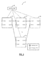
- a network diagram illustrates a network 10 with a controller 50 communicatively coupled to switches 100, 101, 102, 103.
- the switches 100, 101, 102, 103 are communicatively coupled to one another via a core network 120.
- the switches 100, 101, 102, 103 and the core network 120 can utilize packet and/or time-division multiplexing (TDM).
- the controller 50 is an SDN controller and is communicatively coupled to the switches 100, 101, 102, 103 which are edge switches.
- There are a plurality of switches in the core network 120 which are omitted for illustration purposes.
- the controller 50 does not directly connect to or control the plurality of switches in the core network 120.
- the plurality of switches in the core network 120 can utilize distributed control such as through a control plane. Control planes provide an automatic allocation of network resources in an end-to-end manner.
- Exemplary control planes may include Automatically Switched Optical Network (ASON) as defined in G.8080/Y.1304, Architecture for the automatically switched optical network (ASON); Generalized Multi-Protocol Label Switching (GMPLS) Architecture as defined in Request for Comments (RFC): 3945 and the like; Optical Signaling and Routing Protocol (OSRP); or any other type control plane for controlling network elements at one or more layers, and establishing connections there between.
- ASON Automatically Switched Optical Network
- G.8080/Y.1304 Architecture for the automatically switched optical network
- GPLS Generalized Multi-Protocol Label Switching
- RRC Request for Comments
- OSRP Optical Signaling and Routing Protocol
- control planes deal with routing signals at Layers 0, 1, and 2, i.e., photonic signals, time division multiplexing (TDM) signals such as, for example, Synchronous Optical Network (SONET), Synchronous Digital Hierarchy (SDH), Optical Transport Network (OTN), Ethernet, MPLS, and the like.
- Control planes are configured to establish end-to-end signaled connections such as subnetwork connections (SNCs) in ASON or OSRP and label switched paths (LSPs) in GMPLS and MPLS.
- SNCs subnetwork connections
- LSPs label switched paths
- Control planes use the available paths to route the services and program the underlying hardware accordingly. This can be referred to as distributed control since the control plane operates across the plurality of switches in the core network 120.
- the SDN controller 50 can be referred to as centralized control as it directly controls the switches 100, 101, 102, 103 in a centralized manner.
- a block diagram illustrates an SDN/OpenFlow switch model 200.
- the SDN/OpenFlow switch model 200 describes how the switches 100, 101, 102, 103 are modeled in SDN, such as in OpenFlow.
- the switch model 200 includes two switches 202, 204.
- Each of the switches 202, 204 include forwarding tables 210, physical ports 220, and logical ports 230.
- the physical ports 220 are switch defined ports that correspond to a hardware interface of the switches 202, 204. For example, on an Ethernet switch, physical ports map one-to-one to the Ethernet interfaces, on an OTN switch, physical ports map one-to-one to OTU interfaces.
- the OpenFlow switch may be virtualized over the switch hardware. In those cases, an OpenFlow physical port may represent a virtual slice of the corresponding hardware interface of the switch.
- the logical ports 230 are switch defined ports that do not correspond directly to a hardware interface of the switches 202, 204.
- Logical ports are higher level abstractions that may be defined in the switch using non-OpenFlow methods (e.g. OTN ODU connections, link aggregation groups, tunnels, loopback interfaces, etc.).
- the logical ports 230 may include packet encapsulation and may map to various physical ports 220.
- the processing done by the logical port 230 is implementation dependent and must be transparent to OpenFlow processing, and those ports must interact with OpenFlow processing like OpenFlow physical ports.
- a packet associated with a logical port may have an extra pipeline field called Tunnel-ID associated with it and when a packet received on a logical port is sent to the controller 50, both its logical port and its underlying physical port are reported to the controller 50.
- Tunnel-ID an extra pipeline field
- the physical ports 220 are directly coupled physically whereas the logical ports are connected by SDN, the control plane, etc.
- An example is a switch with the physical port being an optical fiber termination that is connected to another switch at the other end of the fiber - the physical port cannot be reconnected to another switch unless you physically manipulate the fiber.
- an OTN ODU connection over the fiber can be viewed as a logical port that is associated with the physical port, but the endpoint of the ODU connection (i.e., the remote end of that logical port) can be reconfigured using the distributed control plane so that the connection terminates on some remote switch.
- the forwarding tables 210 allow switching between the physical ports 220 and the logical ports 230.
- OpenFlow allows remote administration of a switch's packet forwarding tables, by adding, modifying and removing packet matching rules and actions. This way, routing decisions can be made periodically or ad hoc by the controller 50 and translated into rules and actions with a configurable lifespan, which are then deployed to forwarding tables 210, leaving the actual forwarding of matched packets to the switch 202, 204 at wire speed for the duration of those rules. Packets that are unmatched by the switch 202, 204 can be forwarded to the controller 50.
- the controller 50 can then decide to modify existing forwarding table 210 rules on one or more switches or to deploy new rules, to prevent a structural flow of traffic between switch 202, 204 and the controller 50. It could even decide to forward the traffic itself, provided that it has told the switch 202, 204 to forward entire packets instead of just their header.
- a network diagram illustrates the network 10 with the switches 100, 101, 102, 103 illustrating physical port 220 connectivity therebetween.
- the physical ports 220 can be connected through the core network 120.
- Each of the switches 100, 101, 102, 103 are communicatively coupled to the controller 50.
- the physical ports (Pport) 220 can be addressed as X.0.0 where X is the physical port 220 on the switch 100, 101, 102, 103.
- a flowchart illustrates a hybrid control method 300.
- the systems and methods use a combination of the physical ports 220 and the logical ports 230 in the network 10 with the controller 40 to discover virtual topology and provision large bandwidth end-to-end connections across the network using distributed signaling between switches, using these as virtual links for packet or lower rate circuit services.
- the hybrid control method 300 enables the controller 50 to use SDN, centralized control of the switches 100, 101, 102, 103 and control plane, distributed control of the non-adjacent switches in the core network 120.
- non-adjacent switches are switches not connected to the controller 50 and not under its control. The non-adjacent switches can utilize distributed control.
- the hybrid control method 300 includes the controller 50 communicates to the edge switches 100, 101, 102, 103 and the non-adjacent switches utilize distributed control (step 302). That is, the controller 50 talks to the edge switches 100, 101, 102, 103, but does not communicate to the non-adjacent switches.
- the edge switches 100, 101, 102, 103 communicate topology to the controller 50 (step 304).
- the edge switch 100, 101, 102, 103 first informs the controller 50 of the identity and remote endpoint for each physical port 220, and a set of logical ports 230 associated with the physical port 220.
- the controller 50 may or may not know full topology of how edge switches 100, 101, 102, 103 are connected.
- the remote endpoints for the logical ports 230 may be undefined, unless some have been preconfigured to attach to a remote edge switch 100, 101, 102, 103.
- the controller 50 is able to modify the remote endpoints of each logical port 230 to connect to a particular remote edge switch 100, 101, 102, 103 and may optionally assign an explicit path across the network to that logical port, thus controlling end-to-end connections across the network 10.
- the controller 50 can direct logical ports 230 to be connected to non-adjacent switch across the network 10 using a control plane (step 306). Distributed control is then triggered by the port modification instruction from the controller 50 in order to provision the tunnel across the network 10.
- the controller 50 populates the switch's forwarding table matching ingress port and signal to egress port and signal (step 308).
- the controller 50 then configures a flow table in the edge switch 100, 101, 102, 103 to match input packets based on packet characteristics such as header values, and then instantiate forwarding of matching packets to an egress logical port 230 connecting at a lower layer to a destination edge switch 100, 101, 102, 103.
- a network diagram illustrates the network 10 with the switches 100, 101, 102, 103 illustrating physical port 220 and associated logical ports 230.
- the physical ports 220 can be connected through the core network 120.
- Each of the switches 100, 101, 102, 103 are communicatively coupled to the controller 50.
- the physical ports (Pport) 220 can be addressed as X.0.0 where X is the physical port 220 on the switch 100, 101, 102, 103.
- the logical ports (Lport) 230 can be addressed as X.Y.0 where Y is the logical port 230 and X is the associated physical port 220 for the logical port 230.
- a network diagram illustrates the network 10 with the switches 100, 101, 102, 103 illustrating connection/tunnel setup via the physical ports 220 and the associated logical ports 230.
- Pport 3, Lport 1 of the switch 100 is connected to Pport 1, Lport 1 of the switch 101 via a connection 350
- Pport 4, Lport 1 of the switch 100 is connected to Pport 1, Lport 2 of the switch 102 via a connection 352
- Pport 4, Lport 2 of the switch 100 is connected to Pport 1, Lport 1 of the switch 103 via a connection 354.
- the connections 350, 352, 354 connect the physical ports 220 through the core network 120.
- the setup of the paths for the connections 350, 352, 354 can be done through the non-adjacent switches in the core network 120 such as via a control plane.
- the connections 350, 352, 354 can be tunnels, label switched paths, link aggregation groups, etc., i.e., any technique outside of the SDN control.
- the connections 350, 352, 354 can be Virtual Local Area Networks (VLANs).
- VLANs Virtual Local Area Networks
- Controller 50 to Switch 100 Pport 3.0.0: Lport 3.1.0: dest: 101/1.1.0
- Switch 101 to Controller 50 Pport 1.0.0: Lport 1.1.0: newdest: 100/3.1.0
- Switch 102 to Controller 50 Pport 1.0.0: Lport 1.1.0: newdest: 100/3.2.0
- Switch 103 to Controller 50 Pport 1.0.0: Lport 1.1.0: newdest: 100/4.2.0
- a network diagram illustrates the network 10 with the switches 100, 101, 102, 103 illustrating a tunnel setup via the physical ports 220 and the associated logical ports 230 with an explicit route designated in the core network 120.
- Pport 3, Lport 2 of the switch 100 is connected to Pport 1, Lport 1 of the switch 102 via a connection 360.
- the controller 50 can designate an explicit route in the core network 120, e.g. via non-adjacent switches A, B, C.
- the connection 360 can be any type such as the connections 350, 352, 354.
- the connection 360 can be a VLAN.
- Controller 50 to Switch 100 Pport 3.0.0: Lport 3.2.0: dest: 102/1.1.0; ero: ⁇ A; B; C ⁇ Switch 102 to Controller 50: Pport 1.0.0: Lport 1.1.0: newdest: 100/3.2.0
- ERO Explicit Route Object
- DTL Designated Transit List
- a network diagram illustrates the network 10 with the switches 100, 101, 102, 103 illustrating service setup over the connections 350, 352, 354, 360.
- the network 10 has the connections 350, 352, 354, 360 established between logical ports 230, and the controller 50 can route traffic via SDN thereon.
- a physical port 370 on the switch 100 can have the following match/action rules.
- the VLAN 001 is the connection 350
- the VLAN 010 is the connection 360
- the VLAN 011 is the connection 352
- the VLAN 100 is the connection 354.
- Controller 50 to Switch 100 Match: ingress port 1.0; VLAN 001 Action: egress Lport 3.1.0 Match: ingress port 1.0; VLAN010 Action: egress Lport 3.2.0 Match: ingress port 1.0: VLAN011 Action: egress Lport 4.1.0 Match: ingress port 1.0: VLAN100 Action: egress Lport 4.2.0
- a network diagram illustrates the network 10 with the switches 100, 101, 102, 103 illustrating a tunnel setup via the physical ports 220 and the associated logical ports 230 with an explicit route designated in the core network 120 and with metadata included in the signaling message.
- the signaling message from the controller 50 includes additional information such as via a Type-Length-Value (TLV) field - e.g.
- TLV Type-Length-Value
- a block diagram illustrates an exemplary implementation of a switch 400.
- the switch 400 is an Ethernet network switch, but those of ordinary skill in the art will recognize the systems and methods described herein contemplate other types of network elements and other implementations.
- the switch 400 includes a plurality of blades 402, 404 interconnected via an interface 406.
- the blades 402, 404 are also known as line cards, line modules, circuit packs, pluggable modules, etc. and refer generally to components mounted within a chassis, shelf, etc. of a data switching device, i.e., the switch 400.
- Each of the blades 402, 404 can include numerous electronic devices and optical devices mounted on a circuit board along with various interconnects including interfaces to the chassis, shelf, etc.
- the line blades 402 generally include data ports 408 such as a plurality of Ethernet ports.
- the line blade 402 can include a plurality of physical ports disposed on an exterior of the blade 402 for receiving ingress/egress connections.
- the line blades 402 can include switching components to form a switching fabric via the backplane 406 between all of the data ports 408 allowing data traffic to be switched between the data ports 408 on the various line blades 402.
- the switching fabric is a combination of hardware, software, firmware, etc. that moves data coming into the switch 400 out by the correct port to the next switch 400.
- Switching fabric includes switching units, or individual boxes, in a node; integrated circuits contained in the switching units; and programming that allows switching paths to be controlled.
- the switching fabric can be distributed on the blades 402, 404, in a separate blade (not shown), or a combination thereof.
- the line blades 402 can include an Ethernet manager (i.e., a CPU) and a network processor (NP)/application specific integrated circuit (ASIC).
- NP network processor
- ASIC application specific integrated circuit
- the line blades 402 can participate in the systems and methods described herein, such as forming the switches 100, 101, 102, 103 and the non-adjacent switches.
- the control blades 404 include a microprocessor 410, memory 412, software 414, and a network interface 416. Specifically, the microprocessor 410, the memory 412, and the software 414 can collectively control, configure, provision, monitor, etc. the switch 400.
- the network interface 416 may be utilized to communicate with an element manager, a network management system, etc.
- the control blades 404 can include a database 420 that tracks and maintains provisioning, configuration, operational data and the like.
- the database 420 can include a forwarding database (FDB).
- the switch 400 includes two control blades 404 which may operate in a redundant or protected configuration such as 1:1, 1+1, etc.
- the control blades 404 maintain dynamic system information including Layer two forwarding databases, protocol state machines, and the operational status of the ports within the switch 400.
- a block diagram illustrates an exemplary network element 500 for use with the systems and methods described herein.
- the exemplary network element 500 can be a network element that may consolidate the functionality of a multi-service provisioning platform (MSPP), digital cross connect (DCS), Ethernet and/or Optical Transport Network (OTN) switch, dense wave division multiplexed (DWDM) platform, etc. into a single, high-capacity intelligent switching system providing Layer 0, 1, and/or 2 consolidation.
- MSPP multi-service provisioning platform
- DCS digital cross connect
- OTN Optical Transport Network
- DWDM dense wave division multiplexed
- the network element 500 can be any of an OTN add/drop multiplexer (ADM), a multi-service provisioning platform (MSPP), a digital cross-connect (DCS), an optical cross-connect, an optical switch, a router, a switch, a wavelength division multiplexing (WDM) terminal, an access/aggregation device, etc. That is, the network element 500 can be any digital system with ingress and egress digital signals and switching of channels, timeslots, tributary units, etc. While the network element 500 is generally shown as an optical network element, the systems and methods are contemplated for use with any switching fabric, network element, or network based thereon.
- ADM OTN add/drop multiplexer
- MSPP multi-service provisioning platform
- DCS digital cross-connect
- WDM wavelength division multiplexing
- WDM wavelength division multiplexing
- the network element 500 includes common equipment 510, one or more line modules 520, and one or more switch modules 530.
- the common equipment 510 can include power; a control module; operations, administration, maintenance, and provisioning (OAM&P) access; user interface ports; and the like.
- the common equipment 510 can connect to a management system 550 through a data communication network 560 (as well as a Path Computation Element (PCE), Software Defined Network (SDN) controller, OpenFlow controller, etc.).
- the management system 550 can include a network management system (NMS), element management system (EMS), or the like.
- the common equipment 510 can include a control plane processor, such as a controller 600 illustrated in FIG.
- the network element 500 can include an interface 570 for communicatively coupling the common equipment 510, the line modules 520, and the switch modules 530 together.
- the interface 570 can be a backplane, mid-plane, a bus, optical or electrical connectors, or the like.
- the line modules 520 are configured to provide ingress and egress to the switch modules 530 and to external connections on the links to/from the network element 500.
- the line modules 520 can form ingress and egress switches with the switch modules 530 as center stage switches for a three-stage switch, e.g. a three stage Clos switch. Other configurations and/or architectures are also contemplated.
- the line modules 520 can include optical transceivers, such as, for example, 1Gb/s (GbE PHY), 2.5Gb/s (OC-48/STM-1, OTU1, ODU1), 10Gb/s (OC-192/STM-64, OTU2, ODU2, 10GbE PHY), 40Gb/s (OC-768/STM-256, OTU3, ODU3, 40GbE PHY), 100Gb/s (OTU4, ODU4, 100GbE PHY), ODUflex, etc.
- 1Gb/s GbE PHY
- 2.5Gb/s OC-48/STM-1, OTU1, ODU1
- 10Gb/s OC-192/STM-64, OTU2, ODU2, 10GbE PHY
- 40Gb/s OC-768/STM-256, OTU3, ODU3, 40GbE PHY
- 100Gb/s OTU4, ODU4, 100GbE PHY
- ODUflex etc.
- the line modules 520 can include a plurality of optical connections per module and each module may include a flexible rate support for any type of connection, such as, for example, 155 Mb/s, 622 Mb/s, 1 Gb/s, 2.5 Gb/s, 10 Gb/s, 40 Gb/s, and 100 Gb/s, N x 1.25 Gb/s, and any rate in between.
- the line modules 520 can include wavelength division multiplexing interfaces, short reach interfaces, and the like, and can connect to other line modules 520 on remote network elements, end clients, edge routers, and the like, e.g. forming connections on the links.
- the line modules 520 provide ingress and egress ports to the network element 500, and each line module 520 can include one or more physical ports.
- the switch modules 530 are configured to switch channels, timeslots, tributary units, packets, etc. between the line modules 520.
- the switch modules 530 can provide wavelength granularity (Layer 0 switching), SONET/SDH granularity such as Synchronous Transport Signal - 1 (STS-1) and variants/concatenations thereof (STS-n/STS-nc), Synchronous Transport Module level 1 (STM-1) and variants/concatenations thereof, Virtual Container 3 (VC3), etc.; OTN granularity such as Optical Channel Data Unit-1 (ODU1), Optical Channel Data Unit-2 (ODU2), Optical Channel Data Unit-3 (ODU3), Optical Channel Data Unit-4 (ODU4), Optical Channel Data Unit-flex (ODUflex), Optical channel Payload Virtual Containers (OPVCs), ODTUGs, etc.; Ethernet granularity; Digital Signal n (DSn) granularity such as DS0, DS1, DS3, etc.; and the like.
- the switch modules 530 can include Time Division Multiplexed (TDM) (i.e., circuit switching
- the network element 500 can include other components which are omitted for illustration purposes, and that the systems and methods described herein are contemplated for use with a plurality of different network elements with the network element 500 presented as an exemplary type of network element.
- the network element 500 may not include the switch modules 530, but rather have the corresponding functionality in the line modules 520 (or some equivalent) in a distributed fashion.
- other architectures providing ingress, egress, and switching are also contemplated for the systems and methods described herein.
- the systems and methods described herein contemplate use with any network element providing switching of channels, timeslots, tributary units, wavelengths, etc. and using the control plane.
- the network element 500 is merely presented as one exemplary network element 500 for the systems and methods described herein.
- a block diagram illustrates an exemplary implementation of a controller 600.
- the controller 600 provides control plane processing and/or operations, administration, maintenance, and provisioning (OAM&P) for the network element 500.
- the controller 600 can be part of common equipment, such as common equipment 510 in the network element 500, a stand-alone device communicatively coupled to the network element 500 via the DCN 560, or as the controller 50.
- the controller 600 can include a processor 610 which is hardware device for executing software instructions such as operating the control plane.
- the processor 610 can be any custom made or commercially available processor, a central processing unit (CPU), an auxiliary processor among several processors associated with the controller 600, a semiconductor-based microprocessor (in the form of a microchip or chip set), or generally any device for executing software instructions.
- the processor 610 is configured to execute software stored within memory, to communicate data to and from the memory, and to generally control operations of the controller 600 pursuant to the software instructions.
- the controller 600 can also include a network interface 620, a data store 630, memory 640, an I/O interface 650, and the like, all of which are communicatively coupled together and with the processor 610.
- the network interface 620 can be used to enable the controller 600 to communicate on the DCN 560, such as to communicate control plane information to other controllers, to the management system 550, and the like.
- the network interface 620 can include, for example, an Ethernet card (e.g., 10BaseT, Fast Ethernet, Gigabit Ethernet) or a wireless local area network (WLAN) card (e.g., 802.11).
- the network interface 620 can include address, control, and/or data connections to enable appropriate communications on the network.
- the data store 630 can be used to store data, such as control plane information, provisioning data, OAM&P data, etc.
- the data store 630 can include any of volatile memory elements (e.g., random access memory (RAM, such as DRAM, SRAM, SDRAM, and the like)), nonvolatile memory elements (e.g., ROM, hard drive, flash drive, CDROM, and the like), and combinations thereof. Moreover, the data store 630 can incorporate electronic, magnetic, optical, and/or other types of storage media.
- the memory 640 can include any of volatile memory elements (e.g., random access memory (RAM, such as DRAM, SRAM, SDRAM, etc.)), nonvolatile memory elements (e.g., ROM, hard drive, flash drive, CDROM, etc.), and combinations thereof. Moreover, the memory 640 may incorporate electronic, magnetic, optical, and/or other types of storage media. Note that the memory 640 can have a distributed architecture, where various components are situated remotely from one another, but may be accessed by the processor 610.
- the I/O interface 650 includes components for the controller 600 to communicate to other devices.
- the controller 600 is configured to operate the control plane in the network 10. That is, the controller 600 is configured to implement software, processes, algorithms, etc. that control configurable features of the network 10, such as automating discovery of the non-adjacent switches, capacity on the links, port availability on the non-adjacent switches, connectivity between ports; dissemination of topology and bandwidth information between the non-adjacent switches; path computation and creation for connections; network level protection and restoration; and the like.
- the controller 600 can include a topology database that maintains the current topology of the network 10 based on control plane signaling (e.g., HELLO messages) and a connection database that maintains available bandwidth on the links again based on the control plane signaling.
- control plane signaling e.g., HELLO messages
- control plane is a distributed control plane; thus a plurality of the controllers 600 can act together to operate the control plane using the control plane signaling to maintain database synchronization.
- the controller 600 at a source node for a connection is responsible for path computation and establishing by signaling other controllers 600 in the network 10.
- the source node and its controller 600 can signal a path through various techniques such as Resource Reservation Protocol-Traffic Engineering (RSVP-TE) (G.7713.2), Private Network-to-Network Interface (PNNI), Constraint-based Routing Label Distribution Protocol (CR-LDP), etc.
- RSVP-TE Resource Reservation Protocol-Traffic Engineering
- PNNI Private Network-to-Network Interface
- CR-LDP Constraint-based Routing Label Distribution Protocol
- Path computation generally includes determining a path, i.e. traversing the links through the non-adjacent switches from the originating node to the destination node based on a plurality of constraints such as administrative weights on the links, bandwidth availability on the links, etc.
- the controller 50 can utilize an implementation similar to the controller 600.
- some exemplary embodiments described herein may include one or more generic or specialized processors (“one or more processors”) such as microprocessors, digital signal processors, customized processors, and field programmable gate arrays (FPGAs) and unique stored program instructions (including both software and firmware) that control the one or more processors to implement, in conjunction with certain non-processor circuits, some, most, or all of the functions of the methods and/or systems described herein.
- processors such as microprocessors, digital signal processors, customized processors, and field programmable gate arrays (FPGAs) and unique stored program instructions (including both software and firmware) that control the one or more processors to implement, in conjunction with certain non-processor circuits, some, most, or all of the functions of the methods and/or systems described herein.
- FPGAs field programmable gate arrays
- unique stored program instructions including both software and firmware
- some exemplary embodiments may be implemented as a non-transitory computer-readable storage medium having computer readable code stored thereon for programming a computer, server, appliance, device, etc. each of which may include a processor to perform methods as described and claimed herein.
- Examples of such computer-readable storage mediums include, but are not limited to, a hard disk, an optical storage device, a magnetic storage device, a ROM (Read Only Memory), a PROM (Programmable Read Only Memory), an EPROM (Erasable Programmable Read Only Memory), an EEPROM (Electrically Erasable Programmable Read Only Memory), Flash memory, and the like.
- software can include instructions executable by a processor that, in response to such execution, cause a processor or any other circuitry to perform a set of operations, steps, methods, processes, algorithms, etc.
Applications Claiming Priority (1)
| Application Number | Priority Date | Filing Date | Title |
|---|---|---|---|
| US14/314,369 US9774502B2 (en) | 2014-06-25 | 2014-06-25 | Systems and methods for combined software defined networking and distributed network control |
Publications (2)
| Publication Number | Publication Date |
|---|---|
| EP2961116A1 true EP2961116A1 (de) | 2015-12-30 |
| EP2961116B1 EP2961116B1 (de) | 2019-05-08 |
Family
ID=53489863
Family Applications (1)
| Application Number | Title | Priority Date | Filing Date |
|---|---|---|---|
| EP15173439.9A Active EP2961116B1 (de) | 2014-06-25 | 2015-06-23 | Systeme und verfahren für kombinierte software-definierte vernetzung und verteilte netzsteuerung |
Country Status (2)
| Country | Link |
|---|---|
| US (2) | US9774502B2 (de) |
| EP (1) | EP2961116B1 (de) |
Cited By (2)
| Publication number | Priority date | Publication date | Assignee | Title |
|---|---|---|---|---|
| CN111740853A (zh) * | 2019-03-25 | 2020-10-02 | 瞻博网络公司 | 利用出口对等工程来确定优化的业务计划并且实施优化的业务计划 |
| EP3391588B1 (de) * | 2015-12-16 | 2021-12-08 | Telefonaktiebolaget LM Ericsson (PUBL) | Openflow-konfigurierte horizontal geteilte hybride sdn-knoten |
Families Citing this family (42)
| Publication number | Priority date | Publication date | Assignee | Title |
|---|---|---|---|---|
| US20150100560A1 (en) | 2013-10-04 | 2015-04-09 | Nicira, Inc. | Network Controller for Managing Software and Hardware Forwarding Elements |
| US20160006663A1 (en) * | 2014-07-02 | 2016-01-07 | Telefonaktiebolaget L M Ericsson (Publ) | Method and system for compressing forward state of a data network |
| US10469349B2 (en) * | 2014-07-18 | 2019-11-05 | Hewlett Packard Enterprise Development Lp | Conflict detection in a hybrid network device |
| US10439962B2 (en) * | 2014-07-25 | 2019-10-08 | Telefonaktiebolaget Lm Ericsson (Publ) | Packet processing in an OpenFlow switch |
| US10165090B2 (en) * | 2014-08-29 | 2018-12-25 | Metaswitch Networks Ltd. | Transferring routing protocol information between a software defined network and one or more external networks |
| DE102015107073A1 (de) * | 2014-09-08 | 2016-03-10 | Rheinmetall Defence Electronics Gmbh | Vorrichtung und Verfahren zur Steuerung eines Kommunikationsnetzwerks |
| US9762508B2 (en) * | 2014-10-02 | 2017-09-12 | Microsoft Technology Licensing, Llc | Relay optimization using software defined networking |
| US9686199B2 (en) * | 2014-10-21 | 2017-06-20 | Telefonaktiebolaget Lm Ericsson (Publ) | Method and system for implementing ethernet OAM in a software-defined networking (SDN) system |
| CN105721235B (zh) * | 2014-12-05 | 2019-06-11 | 华为技术有限公司 | 一种检测连通性的方法和装置 |
| US9660904B2 (en) | 2015-02-10 | 2017-05-23 | Alcatel Lucent | Method and system for inserting an openflow flow entry into a flow table using openflow protocol |
| US9667440B2 (en) | 2015-02-10 | 2017-05-30 | Alcatel Lucent | Method and system for identifying an incoming interface using openflow protocol |
| US9686137B2 (en) * | 2015-02-10 | 2017-06-20 | Alcatel Lucent | Method and system for identifying an outgoing interface using openflow protocol |
| US9660903B2 (en) | 2015-02-10 | 2017-05-23 | Alcatel Lucent | Method and system for inserting an openflow flow entry into a flow table using openflow protocol |
| US9729442B1 (en) * | 2015-03-01 | 2017-08-08 | Netronome Systems, Inc. | Method of detecting large flows within a switch fabric of an SDN switch |
| US9860350B2 (en) | 2015-05-12 | 2018-01-02 | Huawei Technologies Co., Ltd. | Transport software defined networking (SDN)—logical to physical topology discovery |
| US10015053B2 (en) * | 2015-05-21 | 2018-07-03 | Huawei Technologies Co., Ltd. | Transport software defined networking (SDN)—logical link aggregation (LAG) member signaling |
| US10425319B2 (en) * | 2015-05-21 | 2019-09-24 | Huawei Technologies Co., Ltd. | Transport software defined networking (SDN)—zero configuration adjacency via packet snooping |
| US9967182B2 (en) | 2015-07-31 | 2018-05-08 | Nicira, Inc. | Enabling hardware switches to perform logical routing functionalities |
| US9998324B2 (en) * | 2015-09-30 | 2018-06-12 | Nicira, Inc. | Logical L3 processing for L2 hardware switches |
| US10200235B2 (en) * | 2015-10-31 | 2019-02-05 | Nicira, Inc. | Distributed database structure for logical and physical network data |
| US9438478B1 (en) * | 2015-11-13 | 2016-09-06 | International Business Machines Corporation | Using an SDN controller to automatically test cloud performance |
| US9729948B1 (en) * | 2016-04-07 | 2017-08-08 | Infinera Corporation | Systems and methods for discovery of a controller in openflow networks |
| US10587500B2 (en) * | 2016-04-07 | 2020-03-10 | Infinera Corporation | Intelligent optical restoration in integrated multi-layer networks |
| US10277528B2 (en) * | 2016-08-11 | 2019-04-30 | Fujitsu Limited | Resource management for distributed software defined network controller |
| CN109327409B (zh) * | 2017-07-31 | 2020-09-18 | 华为技术有限公司 | 数据中心网络dcn、dcn中传输流量的方法和交换机 |
| US10721142B1 (en) * | 2018-03-08 | 2020-07-21 | Palantir Technologies Inc. | Computer network troubleshooting |
| US10541877B2 (en) | 2018-05-29 | 2020-01-21 | Ciena Corporation | Dynamic reservation protocol for 5G network slicing |
| US11271795B2 (en) | 2019-02-08 | 2022-03-08 | Ciena Corporation | Systems and methods for proactive network operations |
| US11483212B2 (en) | 2019-02-08 | 2022-10-25 | Ciena Corporation | Safeguarding artificial intelligence-based network control |
| US11895092B2 (en) * | 2019-03-04 | 2024-02-06 | Appgate Cybersecurity, Inc. | Network access controller operation |
| US11343137B2 (en) * | 2019-08-23 | 2022-05-24 | Cisco Technology, Inc. | Dynamic selection of active router based on network conditions |
| US11249986B2 (en) * | 2019-12-17 | 2022-02-15 | Paypal, Inc. | Managing stale connections in a distributed system |
| US11356354B2 (en) | 2020-04-21 | 2022-06-07 | Ciena Corporation | Congruent bidirectional segment routing tunnels |
| US11627017B2 (en) | 2020-10-22 | 2023-04-11 | Ciena Corporation | VPWS signaling using segment routing |
| US11418436B2 (en) | 2020-05-08 | 2022-08-16 | Ciena Corporation | NG-VPLS E-tree signaling using segment routing |
| US11516112B2 (en) | 2020-10-20 | 2022-11-29 | Ciena Corporation | Optimized layer 3 VPN control plane using segment routing |
| US11184276B1 (en) | 2020-05-08 | 2021-11-23 | Ciena Corporation | EVPN signaling using segment routing |
| US11824772B2 (en) | 2020-12-18 | 2023-11-21 | Ciena Corporation | Optimized L2/L3 services over classical MPLS transport |
| US11496354B2 (en) | 2020-06-16 | 2022-11-08 | Ciena Corporation | ECMP fast convergence on path failure using objects in a switching circuit |
| CN114531405B (zh) * | 2020-10-31 | 2023-06-06 | 华为技术有限公司 | 一种流表处理方法及相关设备 |
| US11916753B2 (en) | 2021-07-30 | 2024-02-27 | Ciena Corporation | Governance and interactions of autonomous pipeline-structured control applications |
| US11909671B1 (en) * | 2022-08-18 | 2024-02-20 | Hewlett Packard Enterprise Development Lp | Efficient port reconfiguration |
Citations (1)
| Publication number | Priority date | Publication date | Assignee | Title |
|---|---|---|---|---|
| US20140169158A1 (en) * | 2012-12-17 | 2014-06-19 | Telefonaktiebolaget L M Ericsson (Publ) | Extending the reach and effectiveness of header compression in access networks using sdn |
Family Cites Families (34)
| Publication number | Priority date | Publication date | Assignee | Title |
|---|---|---|---|---|
| US6724756B2 (en) * | 1999-01-12 | 2004-04-20 | Cisco Technology, Inc. | Method for introducing switched virtual connection call redundancy in asynchronous transfer mode networks |
| US8112545B1 (en) | 2000-12-19 | 2012-02-07 | Rockstar Bidco, LP | Distributed network address translation control |
| US7164679B2 (en) | 2004-01-12 | 2007-01-16 | Ciena Corporation | Scalable abstraction of topology across domain boundaries |
| US7633952B2 (en) | 2006-02-27 | 2009-12-15 | Ciena Corporation | Discovery of physically adjacent neighbor devices using a unidirectional in-band process coupled with an out-of-band follow-up process |
| US8724505B2 (en) | 2006-09-01 | 2014-05-13 | Ciena Corporation | Flexible mechanism for supporting virtual private network services based on source-independent distributed advertisements |
| US8045481B2 (en) | 2006-10-20 | 2011-10-25 | Ciena Corporation | System and method for supporting virtualized links at an exterior network-to-network interface |
| US8787170B2 (en) | 2007-01-24 | 2014-07-22 | Ciena Corporation | Methods and systems for existential provisioning of flexible line modules using distributed control |
| US8009681B2 (en) | 2007-03-21 | 2011-08-30 | Ciena Corporation | Methods and systems for interworking RSVP-based external control plane protocols with internal control plane protocols |
| US8433192B2 (en) | 2008-12-08 | 2013-04-30 | Ciena Corporation | Dynamic performance monitoring systems and methods for optical networks |
| WO2011101575A1 (fr) * | 2010-02-16 | 2011-08-25 | France Telecom | Gestion de reseaux prives virtuels |
| US9240923B2 (en) * | 2010-03-23 | 2016-01-19 | Juniper Networks, Inc. | Methods and apparatus for automatically provisioning resources within a distributed control plane of a switch |
| US8958292B2 (en) * | 2010-07-06 | 2015-02-17 | Nicira, Inc. | Network control apparatus and method with port security controls |
| US20120099591A1 (en) * | 2010-10-26 | 2012-04-26 | Dell Products, Lp | System and Method for Scalable Flow Aware Network Architecture for Openflow Based Network Virtualization |
| EP2665229B1 (de) * | 2011-01-13 | 2018-10-17 | Nec Corporation | Netzwerksystem und routingverfahren |
| US8531969B2 (en) | 2011-01-21 | 2013-09-10 | Ciena Corporation | Path computation systems and methods for heterogeneous multi-domain networks |
| EP2692096A1 (de) * | 2011-03-29 | 2014-02-05 | NEC Europe Ltd. | Benutzerverkehrrechenschaftspflicht unter überlastung bei flussbasierten layer-3-switches |
| JP5910811B2 (ja) * | 2011-07-27 | 2016-04-27 | 日本電気株式会社 | スイッチ装置の制御システム、その構成制御装置および構成制御方法 |
| US8606105B2 (en) | 2011-09-15 | 2013-12-10 | Ciena Corporation | Virtual core router and switch systems and methods with a hybrid control architecture |
| US9154433B2 (en) * | 2011-10-25 | 2015-10-06 | Nicira, Inc. | Physical controller |
| US8644149B2 (en) * | 2011-11-22 | 2014-02-04 | Telefonaktiebolaget L M Ericsson (Publ) | Mechanism for packet forwarding using switch pools in flow-based, split-architecture networks |
| US9185166B2 (en) * | 2012-02-28 | 2015-11-10 | International Business Machines Corporation | Disjoint multi-pathing for a data center network |
| US9055006B2 (en) | 2012-06-11 | 2015-06-09 | Radware, Ltd. | Techniques for traffic diversion in software defined networks for mitigating denial of service attacks |
| US8942226B2 (en) | 2012-10-05 | 2015-01-27 | Ciena Corporation | Software defined networking systems and methods via a path computation and control element |
| US8982727B2 (en) | 2012-10-22 | 2015-03-17 | Futurewei Technologies, Inc. | System and apparatus of generalized network controller for a software defined network (SDN) |
| US20140146664A1 (en) * | 2012-11-26 | 2014-05-29 | Level 3 Communications, Llc | Apparatus, system and method for packet switching |
| US8693374B1 (en) * | 2012-12-18 | 2014-04-08 | Juniper Networks, Inc. | Centralized control of an aggregation network with a reduced control plane |
| JP5987920B2 (ja) * | 2013-01-21 | 2016-09-07 | 日本電気株式会社 | 通信システム、制御装置及びネットワークトポロジの管理方法 |
| CN104022960B (zh) * | 2013-02-28 | 2017-05-31 | 新华三技术有限公司 | 基于OpenFlow协议实现PVLAN的方法和装置 |
| WO2014142973A1 (en) * | 2013-03-15 | 2014-09-18 | Hewlett-Packard Development Company, L.P. | Network device architecture adjustments |
| US9270754B2 (en) * | 2013-06-06 | 2016-02-23 | Cisco Technology, Inc. | Software defined networking for storage area networks |
| US10284499B2 (en) * | 2013-08-22 | 2019-05-07 | Arris Enterprises Llc | Dedicated control path architecture for systems of devices |
| US9391844B2 (en) * | 2014-01-15 | 2016-07-12 | Dell Products, L.P. | System and method for network topology management |
| US9369408B1 (en) * | 2014-01-31 | 2016-06-14 | Google Inc. | High performance and resilience in wide area networking |
| US9451095B2 (en) * | 2014-06-17 | 2016-09-20 | Alcatel Lucent | Charging in a software defined network |
-
2014
- 2014-06-25 US US14/314,369 patent/US9774502B2/en active Active
-
2015
- 2015-06-23 EP EP15173439.9A patent/EP2961116B1/de active Active
-
2017
- 2017-08-28 US US15/687,667 patent/US10153948B2/en active Active
Patent Citations (1)
| Publication number | Priority date | Publication date | Assignee | Title |
|---|---|---|---|---|
| US20140169158A1 (en) * | 2012-12-17 | 2014-06-19 | Telefonaktiebolaget L M Ericsson (Publ) | Extending the reach and effectiveness of header compression in access networks using sdn |
Non-Patent Citations (5)
| Title |
|---|
| ASHWOOD-SMITH HUAWEI M SOLIMAN CARLETON UNIVERSITY T WAN HUAWEI P: "SDN State Reduction; draft-ashwood-sdnrg-state-reduction-00.txt", SDN STATE REDUCTION; DRAFT-ASHWOOD-SDNRG-STATE-REDUCTION-00.TXT, INTERNET ENGINEERING TASK FORCE, IETF; STANDARDWORKINGDRAFT, INTERNET SOCIETY (ISOC) 4, RUE DES FALAISES CH- 1205 GENEVA, SWITZERLAND, 3 July 2013 (2013-07-03), pages 1 - 23, XP015094727 * |
| FILSFILS C ET AL: "Segment Routing Centralized Egress Peer Engineering; draft-filsfils-spring-segment-routing-central-epe-01.txt", SEGMENT ROUTING CENTRALIZED EGRESS PEER ENGINEERING; DRAFT-FILSFILS-SPRING-SEGMENT-ROUTING-CENTRAL-EPE-01.TXT, INTERNET ENGINEERING TASK FORCE, IETF; STANDARDWORKINGDRAFT, INTERNET SOCIETY (ISOC) 4, RUE DES FALAISES CH- 1205 GENEVA, SWITZERLAND, 26 May 2014 (2014-05-26), pages 1 - 19, XP015099266 * |
| HUI LU ET AL: "HybNET", 20131209; 20131209 - 20131213, 9 December 2013 (2013-12-09), pages 1 - 6, XP058036329, ISBN: 978-1-4503-2550-9, DOI: 10.1145/2541596.2541602 * |
| RFC 3294, June 2002 (2002-06-01) |
| RFC 5810, March 2010 (2010-03-01) |
Cited By (4)
| Publication number | Priority date | Publication date | Assignee | Title |
|---|---|---|---|---|
| EP3391588B1 (de) * | 2015-12-16 | 2021-12-08 | Telefonaktiebolaget LM Ericsson (PUBL) | Openflow-konfigurierte horizontal geteilte hybride sdn-knoten |
| CN111740853A (zh) * | 2019-03-25 | 2020-10-02 | 瞻博网络公司 | 利用出口对等工程来确定优化的业务计划并且实施优化的业务计划 |
| CN111740853B (zh) * | 2019-03-25 | 2022-03-08 | 瞻博网络公司 | 利用出口对等工程来确定优化的业务计划并且实施优化的业务计划 |
| US11496389B2 (en) | 2019-03-25 | 2022-11-08 | Juniper Networks, Inc. | Utilizing egress peer engineering to determine optimized traffic plans and to implement an optimized traffic plan |
Also Published As
| Publication number | Publication date |
|---|---|
| US10153948B2 (en) | 2018-12-11 |
| US20170373942A1 (en) | 2017-12-28 |
| US9774502B2 (en) | 2017-09-26 |
| EP2961116B1 (de) | 2019-05-08 |
| US20150381428A1 (en) | 2015-12-31 |
Similar Documents
| Publication | Publication Date | Title |
|---|---|---|
| US10153948B2 (en) | Systems and methods for combined software defined networking and distributed network control | |
| US10158448B2 (en) | Multilayer resource management and arbitration in transport networks | |
| US10027762B2 (en) | Service preemption selection systems and methods in networks | |
| US9680588B2 (en) | OTN switching systems and methods using an SDN controller and match/action rules | |
| US9832548B2 (en) | Flexible behavior modification during restoration in optical networks | |
| US10355935B2 (en) | Reduced link bandwidth update systems and methods for improved scalability, efficiency, and performance | |
| US8606105B2 (en) | Virtual core router and switch systems and methods with a hybrid control architecture | |
| US9538264B2 (en) | ODUflex resizing systems and methods | |
| US10003867B2 (en) | Disjoint path computation systems and methods in optical networks | |
| US10187144B2 (en) | Multi-layer network resiliency systems and methods | |
| US8553707B2 (en) | Administrative boundaries in single or multiple domain optical networks | |
| US10097306B1 (en) | Path computation systems and methods in control plane based networks for photonic layer topologies | |
| US9628172B2 (en) | Optimization of photonic services with colorless and directionless architecture | |
| US20130114953A1 (en) | Optical transport network port protection systems and methods using flexible switch criteria | |
| US20140147107A1 (en) | Drop port based shared risk link group systems and methods | |
| US10063336B1 (en) | Protected transponded services integrated with control plane switched services | |
| US9538573B2 (en) | Systems and methods for managing call connections from non-originating nodes in networks | |
| US10382276B2 (en) | Control plane routing systems and methods for pervasive maintenance | |
| US9237090B2 (en) | Network routing systems and methods for validation of paths subsequent to validation failure | |
| US9509593B2 (en) | Systems and methods for diverse connection signaling from disparate source nodes in distributed connection-oriented networks | |
| US10079753B2 (en) | Multi-drop unidirectional services in a network |
Legal Events
| Date | Code | Title | Description |
|---|---|---|---|
| PUAI | Public reference made under article 153(3) epc to a published international application that has entered the european phase |
Free format text: ORIGINAL CODE: 0009012 |
|
| AK | Designated contracting states |
Kind code of ref document: A1 Designated state(s): AL AT BE BG CH CY CZ DE DK EE ES FI FR GB GR HR HU IE IS IT LI LT LU LV MC MK MT NL NO PL PT RO RS SE SI SK SM TR |
|
| AX | Request for extension of the european patent |
Extension state: BA ME |
|
| 17P | Request for examination filed |
Effective date: 20160630 |
|
| RBV | Designated contracting states (corrected) |
Designated state(s): AL AT BE BG CH CY CZ DE DK EE ES FI FR GB GR HR HU IE IS IT LI LT LU LV MC MK MT NL NO PL PT RO RS SE SI SK SM TR |
|
| RIC1 | Information provided on ipc code assigned before grant |
Ipc: H04L 12/937 20130101ALI20180913BHEP Ipc: H04L 12/721 20130101AFI20180913BHEP Ipc: H04L 12/715 20130101ALI20180913BHEP Ipc: H04L 12/24 20060101ALI20180913BHEP Ipc: H04L 12/717 20130101ALI20180913BHEP |
|
| GRAP | Despatch of communication of intention to grant a patent |
Free format text: ORIGINAL CODE: EPIDOSNIGR1 |
|
| STAA | Information on the status of an ep patent application or granted ep patent |
Free format text: STATUS: GRANT OF PATENT IS INTENDED |
|
| INTG | Intention to grant announced |
Effective date: 20181023 |
|
| GRAJ | Information related to disapproval of communication of intention to grant by the applicant or resumption of examination proceedings by the epo deleted |
Free format text: ORIGINAL CODE: EPIDOSDIGR1 |
|
| STAA | Information on the status of an ep patent application or granted ep patent |
Free format text: STATUS: REQUEST FOR EXAMINATION WAS MADE |
|
| GRAP | Despatch of communication of intention to grant a patent |
Free format text: ORIGINAL CODE: EPIDOSNIGR1 |
|
| STAA | Information on the status of an ep patent application or granted ep patent |
Free format text: STATUS: GRANT OF PATENT IS INTENDED |
|
| INTC | Intention to grant announced (deleted) | ||
| GRAS | Grant fee paid |
Free format text: ORIGINAL CODE: EPIDOSNIGR3 |
|
| GRAA | (expected) grant |
Free format text: ORIGINAL CODE: 0009210 |
|
| STAA | Information on the status of an ep patent application or granted ep patent |
Free format text: STATUS: THE PATENT HAS BEEN GRANTED |
|
| INTG | Intention to grant announced |
Effective date: 20190318 |
|
| AK | Designated contracting states |
Kind code of ref document: B1 Designated state(s): AL AT BE BG CH CY CZ DE DK EE ES FI FR GB GR HR HU IE IS IT LI LT LU LV MC MK MT NL NO PL PT RO RS SE SI SK SM TR |
|
| REG | Reference to a national code |
Ref country code: GB Ref legal event code: FG4D |
|
| REG | Reference to a national code |
Ref country code: CH Ref legal event code: EP Ref country code: AT Ref legal event code: REF Ref document number: 1131952 Country of ref document: AT Kind code of ref document: T Effective date: 20190515 |
|
| REG | Reference to a national code |
Ref country code: DE Ref legal event code: R096 Ref document number: 602015029675 Country of ref document: DE Ref country code: IE Ref legal event code: FG4D |
|
| REG | Reference to a national code |
Ref country code: NL Ref legal event code: MP Effective date: 20190508 |
|
| REG | Reference to a national code |
Ref country code: LT Ref legal event code: MG4D |
|
| PG25 | Lapsed in a contracting state [announced via postgrant information from national office to epo] |
Ref country code: LT Free format text: LAPSE BECAUSE OF FAILURE TO SUBMIT A TRANSLATION OF THE DESCRIPTION OR TO PAY THE FEE WITHIN THE PRESCRIBED TIME-LIMIT Effective date: 20190508 Ref country code: HR Free format text: LAPSE BECAUSE OF FAILURE TO SUBMIT A TRANSLATION OF THE DESCRIPTION OR TO PAY THE FEE WITHIN THE PRESCRIBED TIME-LIMIT Effective date: 20190508 Ref country code: FI Free format text: LAPSE BECAUSE OF FAILURE TO SUBMIT A TRANSLATION OF THE DESCRIPTION OR TO PAY THE FEE WITHIN THE PRESCRIBED TIME-LIMIT Effective date: 20190508 Ref country code: AL Free format text: LAPSE BECAUSE OF FAILURE TO SUBMIT A TRANSLATION OF THE DESCRIPTION OR TO PAY THE FEE WITHIN THE PRESCRIBED TIME-LIMIT Effective date: 20190508 Ref country code: NO Free format text: LAPSE BECAUSE OF FAILURE TO SUBMIT A TRANSLATION OF THE DESCRIPTION OR TO PAY THE FEE WITHIN THE PRESCRIBED TIME-LIMIT Effective date: 20190808 Ref country code: SE Free format text: LAPSE BECAUSE OF FAILURE TO SUBMIT A TRANSLATION OF THE DESCRIPTION OR TO PAY THE FEE WITHIN THE PRESCRIBED TIME-LIMIT Effective date: 20190508 Ref country code: PT Free format text: LAPSE BECAUSE OF FAILURE TO SUBMIT A TRANSLATION OF THE DESCRIPTION OR TO PAY THE FEE WITHIN THE PRESCRIBED TIME-LIMIT Effective date: 20190908 Ref country code: ES Free format text: LAPSE BECAUSE OF FAILURE TO SUBMIT A TRANSLATION OF THE DESCRIPTION OR TO PAY THE FEE WITHIN THE PRESCRIBED TIME-LIMIT Effective date: 20190508 Ref country code: NL Free format text: LAPSE BECAUSE OF FAILURE TO SUBMIT A TRANSLATION OF THE DESCRIPTION OR TO PAY THE FEE WITHIN THE PRESCRIBED TIME-LIMIT Effective date: 20190508 |
|
| PG25 | Lapsed in a contracting state [announced via postgrant information from national office to epo] |
Ref country code: RS Free format text: LAPSE BECAUSE OF FAILURE TO SUBMIT A TRANSLATION OF THE DESCRIPTION OR TO PAY THE FEE WITHIN THE PRESCRIBED TIME-LIMIT Effective date: 20190508 Ref country code: BG Free format text: LAPSE BECAUSE OF FAILURE TO SUBMIT A TRANSLATION OF THE DESCRIPTION OR TO PAY THE FEE WITHIN THE PRESCRIBED TIME-LIMIT Effective date: 20190808 Ref country code: LV Free format text: LAPSE BECAUSE OF FAILURE TO SUBMIT A TRANSLATION OF THE DESCRIPTION OR TO PAY THE FEE WITHIN THE PRESCRIBED TIME-LIMIT Effective date: 20190508 Ref country code: GR Free format text: LAPSE BECAUSE OF FAILURE TO SUBMIT A TRANSLATION OF THE DESCRIPTION OR TO PAY THE FEE WITHIN THE PRESCRIBED TIME-LIMIT Effective date: 20190809 |
|
| REG | Reference to a national code |
Ref country code: AT Ref legal event code: MK05 Ref document number: 1131952 Country of ref document: AT Kind code of ref document: T Effective date: 20190508 |
|
| PG25 | Lapsed in a contracting state [announced via postgrant information from national office to epo] |
Ref country code: EE Free format text: LAPSE BECAUSE OF FAILURE TO SUBMIT A TRANSLATION OF THE DESCRIPTION OR TO PAY THE FEE WITHIN THE PRESCRIBED TIME-LIMIT Effective date: 20190508 Ref country code: SK Free format text: LAPSE BECAUSE OF FAILURE TO SUBMIT A TRANSLATION OF THE DESCRIPTION OR TO PAY THE FEE WITHIN THE PRESCRIBED TIME-LIMIT Effective date: 20190508 Ref country code: AT Free format text: LAPSE BECAUSE OF FAILURE TO SUBMIT A TRANSLATION OF THE DESCRIPTION OR TO PAY THE FEE WITHIN THE PRESCRIBED TIME-LIMIT Effective date: 20190508 Ref country code: DK Free format text: LAPSE BECAUSE OF FAILURE TO SUBMIT A TRANSLATION OF THE DESCRIPTION OR TO PAY THE FEE WITHIN THE PRESCRIBED TIME-LIMIT Effective date: 20190508 Ref country code: RO Free format text: LAPSE BECAUSE OF FAILURE TO SUBMIT A TRANSLATION OF THE DESCRIPTION OR TO PAY THE FEE WITHIN THE PRESCRIBED TIME-LIMIT Effective date: 20190508 Ref country code: CZ Free format text: LAPSE BECAUSE OF FAILURE TO SUBMIT A TRANSLATION OF THE DESCRIPTION OR TO PAY THE FEE WITHIN THE PRESCRIBED TIME-LIMIT Effective date: 20190508 |
|
| REG | Reference to a national code |
Ref country code: CH Ref legal event code: PL |
|
| REG | Reference to a national code |
Ref country code: DE Ref legal event code: R097 Ref document number: 602015029675 Country of ref document: DE |
|
| PG25 | Lapsed in a contracting state [announced via postgrant information from national office to epo] |
Ref country code: SM Free format text: LAPSE BECAUSE OF FAILURE TO SUBMIT A TRANSLATION OF THE DESCRIPTION OR TO PAY THE FEE WITHIN THE PRESCRIBED TIME-LIMIT Effective date: 20190508 Ref country code: MC Free format text: LAPSE BECAUSE OF FAILURE TO SUBMIT A TRANSLATION OF THE DESCRIPTION OR TO PAY THE FEE WITHIN THE PRESCRIBED TIME-LIMIT Effective date: 20190508 Ref country code: IT Free format text: LAPSE BECAUSE OF FAILURE TO SUBMIT A TRANSLATION OF THE DESCRIPTION OR TO PAY THE FEE WITHIN THE PRESCRIBED TIME-LIMIT Effective date: 20190508 |
|
| PLBE | No opposition filed within time limit |
Free format text: ORIGINAL CODE: 0009261 |
|
| STAA | Information on the status of an ep patent application or granted ep patent |
Free format text: STATUS: NO OPPOSITION FILED WITHIN TIME LIMIT |
|
| REG | Reference to a national code |
Ref country code: BE Ref legal event code: MM Effective date: 20190630 |
|
| PG25 | Lapsed in a contracting state [announced via postgrant information from national office to epo] |
Ref country code: TR Free format text: LAPSE BECAUSE OF FAILURE TO SUBMIT A TRANSLATION OF THE DESCRIPTION OR TO PAY THE FEE WITHIN THE PRESCRIBED TIME-LIMIT Effective date: 20190508 |
|
| 26N | No opposition filed |
Effective date: 20200211 |
|
| PG25 | Lapsed in a contracting state [announced via postgrant information from national office to epo] |
Ref country code: PL Free format text: LAPSE BECAUSE OF FAILURE TO SUBMIT A TRANSLATION OF THE DESCRIPTION OR TO PAY THE FEE WITHIN THE PRESCRIBED TIME-LIMIT Effective date: 20190508 Ref country code: IE Free format text: LAPSE BECAUSE OF NON-PAYMENT OF DUE FEES Effective date: 20190623 |
|
| PG25 | Lapsed in a contracting state [announced via postgrant information from national office to epo] |
Ref country code: BE Free format text: LAPSE BECAUSE OF NON-PAYMENT OF DUE FEES Effective date: 20190630 Ref country code: SI Free format text: LAPSE BECAUSE OF FAILURE TO SUBMIT A TRANSLATION OF THE DESCRIPTION OR TO PAY THE FEE WITHIN THE PRESCRIBED TIME-LIMIT Effective date: 20190508 Ref country code: LI Free format text: LAPSE BECAUSE OF NON-PAYMENT OF DUE FEES Effective date: 20190630 Ref country code: LU Free format text: LAPSE BECAUSE OF NON-PAYMENT OF DUE FEES Effective date: 20190623 Ref country code: CH Free format text: LAPSE BECAUSE OF NON-PAYMENT OF DUE FEES Effective date: 20190630 |
|
| PG25 | Lapsed in a contracting state [announced via postgrant information from national office to epo] |
Ref country code: CY Free format text: LAPSE BECAUSE OF FAILURE TO SUBMIT A TRANSLATION OF THE DESCRIPTION OR TO PAY THE FEE WITHIN THE PRESCRIBED TIME-LIMIT Effective date: 20190508 |
|
| PG25 | Lapsed in a contracting state [announced via postgrant information from national office to epo] |
Ref country code: IS Free format text: LAPSE BECAUSE OF FAILURE TO SUBMIT A TRANSLATION OF THE DESCRIPTION OR TO PAY THE FEE WITHIN THE PRESCRIBED TIME-LIMIT Effective date: 20190908 |
|
| PG25 | Lapsed in a contracting state [announced via postgrant information from national office to epo] |
Ref country code: HU Free format text: LAPSE BECAUSE OF FAILURE TO SUBMIT A TRANSLATION OF THE DESCRIPTION OR TO PAY THE FEE WITHIN THE PRESCRIBED TIME-LIMIT; INVALID AB INITIO Effective date: 20150623 Ref country code: MT Free format text: LAPSE BECAUSE OF FAILURE TO SUBMIT A TRANSLATION OF THE DESCRIPTION OR TO PAY THE FEE WITHIN THE PRESCRIBED TIME-LIMIT Effective date: 20190508 |
|
| REG | Reference to a national code |
Ref country code: DE Ref legal event code: R079 Ref document number: 602015029675 Country of ref document: DE Free format text: PREVIOUS MAIN CLASS: H04L0012721000 Ipc: H04L0045000000 |
|
| PG25 | Lapsed in a contracting state [announced via postgrant information from national office to epo] |
Ref country code: MK Free format text: LAPSE BECAUSE OF FAILURE TO SUBMIT A TRANSLATION OF THE DESCRIPTION OR TO PAY THE FEE WITHIN THE PRESCRIBED TIME-LIMIT Effective date: 20190508 |
|
| P01 | Opt-out of the competence of the unified patent court (upc) registered |
Effective date: 20230515 |
|
| PGFP | Annual fee paid to national office [announced via postgrant information from national office to epo] |
Ref country code: FR Payment date: 20230628 Year of fee payment: 9 Ref country code: DE Payment date: 20230620 Year of fee payment: 9 |
|
| PGFP | Annual fee paid to national office [announced via postgrant information from national office to epo] |
Ref country code: GB Payment date: 20230622 Year of fee payment: 9 |