EP2960770A1 - Device - Google Patents
Device Download PDFInfo
- Publication number
- EP2960770A1 EP2960770A1 EP14753532.2A EP14753532A EP2960770A1 EP 2960770 A1 EP2960770 A1 EP 2960770A1 EP 14753532 A EP14753532 A EP 14753532A EP 2960770 A1 EP2960770 A1 EP 2960770A1
- Authority
- EP
- European Patent Office
- Prior art keywords
- display
- display area
- panel
- touch screen
- mobile phone
- Prior art date
- Legal status (The legal status is an assumption and is not a legal conclusion. Google has not performed a legal analysis and makes no representation as to the accuracy of the status listed.)
- Ceased
Links
Images


Classifications
-
- G—PHYSICS
- G06—COMPUTING; CALCULATING OR COUNTING
- G06F—ELECTRIC DIGITAL DATA PROCESSING
- G06F3/00—Input arrangements for transferring data to be processed into a form capable of being handled by the computer; Output arrangements for transferring data from processing unit to output unit, e.g. interface arrangements
- G06F3/01—Input arrangements or combined input and output arrangements for interaction between user and computer
- G06F3/048—Interaction techniques based on graphical user interfaces [GUI]
- G06F3/0487—Interaction techniques based on graphical user interfaces [GUI] using specific features provided by the input device, e.g. functions controlled by the rotation of a mouse with dual sensing arrangements, or of the nature of the input device, e.g. tap gestures based on pressure sensed by a digitiser
- G06F3/0488—Interaction techniques based on graphical user interfaces [GUI] using specific features provided by the input device, e.g. functions controlled by the rotation of a mouse with dual sensing arrangements, or of the nature of the input device, e.g. tap gestures based on pressure sensed by a digitiser using a touch-screen or digitiser, e.g. input of commands through traced gestures
- G06F3/04883—Interaction techniques based on graphical user interfaces [GUI] using specific features provided by the input device, e.g. functions controlled by the rotation of a mouse with dual sensing arrangements, or of the nature of the input device, e.g. tap gestures based on pressure sensed by a digitiser using a touch-screen or digitiser, e.g. input of commands through traced gestures for inputting data by handwriting, e.g. gesture or text
-
- G—PHYSICS
- G06—COMPUTING; CALCULATING OR COUNTING
- G06F—ELECTRIC DIGITAL DATA PROCESSING
- G06F1/00—Details not covered by groups G06F3/00 - G06F13/00 and G06F21/00
- G06F1/16—Constructional details or arrangements
- G06F1/1613—Constructional details or arrangements for portable computers
- G06F1/1626—Constructional details or arrangements for portable computers with a single-body enclosure integrating a flat display, e.g. Personal Digital Assistants [PDAs]
-
- G—PHYSICS
- G06—COMPUTING; CALCULATING OR COUNTING
- G06F—ELECTRIC DIGITAL DATA PROCESSING
- G06F1/00—Details not covered by groups G06F3/00 - G06F13/00 and G06F21/00
- G06F1/16—Constructional details or arrangements
- G06F1/1613—Constructional details or arrangements for portable computers
- G06F1/1633—Constructional details or arrangements of portable computers not specific to the type of enclosures covered by groups G06F1/1615 - G06F1/1626
- G06F1/1637—Details related to the display arrangement, including those related to the mounting of the display in the housing
- G06F1/1643—Details related to the display arrangement, including those related to the mounting of the display in the housing the display being associated to a digitizer, e.g. laptops that can be used as penpads
-
- G—PHYSICS
- G06—COMPUTING; CALCULATING OR COUNTING
- G06F—ELECTRIC DIGITAL DATA PROCESSING
- G06F1/00—Details not covered by groups G06F3/00 - G06F13/00 and G06F21/00
- G06F1/16—Constructional details or arrangements
- G06F1/1613—Constructional details or arrangements for portable computers
- G06F1/1633—Constructional details or arrangements of portable computers not specific to the type of enclosures covered by groups G06F1/1615 - G06F1/1626
- G06F1/1637—Details related to the display arrangement, including those related to the mounting of the display in the housing
- G06F1/1647—Details related to the display arrangement, including those related to the mounting of the display in the housing including at least an additional display
-
- G—PHYSICS
- G06—COMPUTING; CALCULATING OR COUNTING
- G06F—ELECTRIC DIGITAL DATA PROCESSING
- G06F1/00—Details not covered by groups G06F3/00 - G06F13/00 and G06F21/00
- G06F1/16—Constructional details or arrangements
- G06F1/1613—Constructional details or arrangements for portable computers
- G06F1/1633—Constructional details or arrangements of portable computers not specific to the type of enclosures covered by groups G06F1/1615 - G06F1/1626
- G06F1/1637—Details related to the display arrangement, including those related to the mounting of the display in the housing
- G06F1/1652—Details related to the display arrangement, including those related to the mounting of the display in the housing the display being flexible, e.g. mimicking a sheet of paper, or rollable
-
- G—PHYSICS
- G06—COMPUTING; CALCULATING OR COUNTING
- G06F—ELECTRIC DIGITAL DATA PROCESSING
- G06F1/00—Details not covered by groups G06F3/00 - G06F13/00 and G06F21/00
- G06F1/16—Constructional details or arrangements
- G06F1/1613—Constructional details or arrangements for portable computers
- G06F1/1633—Constructional details or arrangements of portable computers not specific to the type of enclosures covered by groups G06F1/1615 - G06F1/1626
- G06F1/1684—Constructional details or arrangements related to integrated I/O peripherals not covered by groups G06F1/1635 - G06F1/1675
-
- G—PHYSICS
- G06—COMPUTING; CALCULATING OR COUNTING
- G06F—ELECTRIC DIGITAL DATA PROCESSING
- G06F3/00—Input arrangements for transferring data to be processed into a form capable of being handled by the computer; Output arrangements for transferring data from processing unit to output unit, e.g. interface arrangements
- G06F3/01—Input arrangements or combined input and output arrangements for interaction between user and computer
- G06F3/017—Gesture based interaction, e.g. based on a set of recognized hand gestures
-
- G—PHYSICS
- G06—COMPUTING; CALCULATING OR COUNTING
- G06F—ELECTRIC DIGITAL DATA PROCESSING
- G06F3/00—Input arrangements for transferring data to be processed into a form capable of being handled by the computer; Output arrangements for transferring data from processing unit to output unit, e.g. interface arrangements
- G06F3/01—Input arrangements or combined input and output arrangements for interaction between user and computer
- G06F3/03—Arrangements for converting the position or the displacement of a member into a coded form
- G06F3/033—Pointing devices displaced or positioned by the user, e.g. mice, trackballs, pens or joysticks; Accessories therefor
- G06F3/0354—Pointing devices displaced or positioned by the user, e.g. mice, trackballs, pens or joysticks; Accessories therefor with detection of 2D relative movements between the device, or an operating part thereof, and a plane or surface, e.g. 2D mice, trackballs, pens or pucks
- G06F3/03547—Touch pads, in which fingers can move on a surface
-
- G—PHYSICS
- G06—COMPUTING; CALCULATING OR COUNTING
- G06F—ELECTRIC DIGITAL DATA PROCESSING
- G06F3/00—Input arrangements for transferring data to be processed into a form capable of being handled by the computer; Output arrangements for transferring data from processing unit to output unit, e.g. interface arrangements
- G06F3/01—Input arrangements or combined input and output arrangements for interaction between user and computer
- G06F3/03—Arrangements for converting the position or the displacement of a member into a coded form
- G06F3/041—Digitisers, e.g. for touch screens or touch pads, characterised by the transducing means
- G06F3/0412—Digitisers structurally integrated in a display
-
- G—PHYSICS
- G06—COMPUTING; CALCULATING OR COUNTING
- G06F—ELECTRIC DIGITAL DATA PROCESSING
- G06F3/00—Input arrangements for transferring data to be processed into a form capable of being handled by the computer; Output arrangements for transferring data from processing unit to output unit, e.g. interface arrangements
- G06F3/01—Input arrangements or combined input and output arrangements for interaction between user and computer
- G06F3/03—Arrangements for converting the position or the displacement of a member into a coded form
- G06F3/041—Digitisers, e.g. for touch screens or touch pads, characterised by the transducing means
- G06F3/0416—Control or interface arrangements specially adapted for digitisers
-
- G—PHYSICS
- G06—COMPUTING; CALCULATING OR COUNTING
- G06F—ELECTRIC DIGITAL DATA PROCESSING
- G06F3/00—Input arrangements for transferring data to be processed into a form capable of being handled by the computer; Output arrangements for transferring data from processing unit to output unit, e.g. interface arrangements
- G06F3/01—Input arrangements or combined input and output arrangements for interaction between user and computer
- G06F3/048—Interaction techniques based on graphical user interfaces [GUI]
- G06F3/0481—Interaction techniques based on graphical user interfaces [GUI] based on specific properties of the displayed interaction object or a metaphor-based environment, e.g. interaction with desktop elements like windows or icons, or assisted by a cursor's changing behaviour or appearance
- G06F3/04817—Interaction techniques based on graphical user interfaces [GUI] based on specific properties of the displayed interaction object or a metaphor-based environment, e.g. interaction with desktop elements like windows or icons, or assisted by a cursor's changing behaviour or appearance using icons
-
- G—PHYSICS
- G06—COMPUTING; CALCULATING OR COUNTING
- G06F—ELECTRIC DIGITAL DATA PROCESSING
- G06F3/00—Input arrangements for transferring data to be processed into a form capable of being handled by the computer; Output arrangements for transferring data from processing unit to output unit, e.g. interface arrangements
- G06F3/01—Input arrangements or combined input and output arrangements for interaction between user and computer
- G06F3/048—Interaction techniques based on graphical user interfaces [GUI]
- G06F3/0484—Interaction techniques based on graphical user interfaces [GUI] for the control of specific functions or operations, e.g. selecting or manipulating an object, an image or a displayed text element, setting a parameter value or selecting a range
- G06F3/0485—Scrolling or panning
-
- G—PHYSICS
- G06—COMPUTING; CALCULATING OR COUNTING
- G06F—ELECTRIC DIGITAL DATA PROCESSING
- G06F3/00—Input arrangements for transferring data to be processed into a form capable of being handled by the computer; Output arrangements for transferring data from processing unit to output unit, e.g. interface arrangements
- G06F3/01—Input arrangements or combined input and output arrangements for interaction between user and computer
- G06F3/048—Interaction techniques based on graphical user interfaces [GUI]
- G06F3/0487—Interaction techniques based on graphical user interfaces [GUI] using specific features provided by the input device, e.g. functions controlled by the rotation of a mouse with dual sensing arrangements, or of the nature of the input device, e.g. tap gestures based on pressure sensed by a digitiser
- G06F3/0488—Interaction techniques based on graphical user interfaces [GUI] using specific features provided by the input device, e.g. functions controlled by the rotation of a mouse with dual sensing arrangements, or of the nature of the input device, e.g. tap gestures based on pressure sensed by a digitiser using a touch-screen or digitiser, e.g. input of commands through traced gestures
-
- G—PHYSICS
- G06—COMPUTING; CALCULATING OR COUNTING
- G06F—ELECTRIC DIGITAL DATA PROCESSING
- G06F2203/00—Indexing scheme relating to G06F3/00 - G06F3/048
- G06F2203/041—Indexing scheme relating to G06F3/041 - G06F3/045
- G06F2203/04101—2.5D-digitiser, i.e. digitiser detecting the X/Y position of the input means, finger or stylus, also when it does not touch, but is proximate to the digitiser's interaction surface and also measures the distance of the input means within a short range in the Z direction, possibly with a separate measurement setup
-
- G—PHYSICS
- G06—COMPUTING; CALCULATING OR COUNTING
- G06F—ELECTRIC DIGITAL DATA PROCESSING
- G06F2203/00—Indexing scheme relating to G06F3/00 - G06F3/048
- G06F2203/041—Indexing scheme relating to G06F3/041 - G06F3/045
- G06F2203/04102—Flexible digitiser, i.e. constructional details for allowing the whole digitising part of a device to be flexed or rolled like a sheet of paper
-
- G—PHYSICS
- G06—COMPUTING; CALCULATING OR COUNTING
- G06F—ELECTRIC DIGITAL DATA PROCESSING
- G06F2203/00—Indexing scheme relating to G06F3/00 - G06F3/048
- G06F2203/041—Indexing scheme relating to G06F3/041 - G06F3/045
- G06F2203/04103—Manufacturing, i.e. details related to manufacturing processes specially suited for touch sensitive devices
-
- G—PHYSICS
- G06—COMPUTING; CALCULATING OR COUNTING
- G06F—ELECTRIC DIGITAL DATA PROCESSING
- G06F2203/00—Indexing scheme relating to G06F3/00 - G06F3/048
- G06F2203/041—Indexing scheme relating to G06F3/041 - G06F3/045
- G06F2203/04104—Multi-touch detection in digitiser, i.e. details about the simultaneous detection of a plurality of touching locations, e.g. multiple fingers or pen and finger
-
- G—PHYSICS
- G06—COMPUTING; CALCULATING OR COUNTING
- G06F—ELECTRIC DIGITAL DATA PROCESSING
- G06F2203/00—Indexing scheme relating to G06F3/00 - G06F3/048
- G06F2203/048—Indexing scheme relating to G06F3/048
- G06F2203/04803—Split screen, i.e. subdividing the display area or the window area into separate subareas
Definitions
- the present invention relates to a device provided with a touch screen display.
- the device provided with the touch screen display includes smart phones and tablets.
- the device provided with the touch screen display detects a gesture of fingers or a stylus pen through the touch screen display. Then, the device provided with the touch screen display operates according to the detected gesture. Examples of an operation according to a detected gesture are described in Patent Literature 1 for instance.
- OS Operating System
- Android a registered trademark
- BlackBerry a registered trademark
- Symbian a registered trademark
- iOS a registered trademark
- Windows a registered trademark
- Patent Literature 1 WO 2008/086302
- An object of the present invention is to provide a device having improved operability.
- a device includes: a housing that has a first surface, a second surface, and a third surface connecting the first surface and the second surface; a touch screen that is disposed on the third surface of the housing; at least one display that is a display, which is disposed inside the housing and has a first display area performing display on the first surface and a second display area performing display on the second surface; and a controller that displays a screen according to a first operation in the first display area if the first operation is detected by the touch screen of the third surface, and displays a screen according to a second operation different from the first operation in the second display area if the second operation is detected by the touch screen of the third surface.
- the first operation may be a first gesture operation from the third surface toward the first surface
- the second operation may be a second gesture operation from the third surface toward the second surface
- the first operation and the second operation may be operations on the same icon on the touch screen.
- the controller may change the volume of call sound in response to a swipe operation on the touch screen of the third surface.
- the display may be one flexible display, and the flexible display may have the first display area and the second display area.
- a device includes: a housing that has a first surface, a second surface, and a third surface connecting the first surface and the second surface; a display that is a flexible display, which is disposed inside the housing, and has a first display area performing display on the first surface, a second display area performing display on the second surface and a third display area performing display on the third surface; a posture detection unit that detects a posture; and a controller that controls display of the third display area in response to the posture detected by the posture detection unit.
- the device may include a proximity sensor that determines whether it is close to an object, and in a case where the posture detected by the posture detection unit is in a vertical direction and the proximity sensor determines that it is close to an object, the controller may control the third display area such that the third display area displays predetermined information.
- the posture detection unit may detect whether one of the first display area and the second display area is positioned upper than the other of the first display area and the second display area, and the controller may display predetermined information in the one of the first display area and the second display area positioned upper than the other.
- a device includes: a housing; a panel that is a panel, which is attached to the housing and has a first surface, a second surface, and a third surface connecting the first surface and the second surface; a display that is a display, which is attached to the panel and has a first display area performing display on the first surface, a second display area performing display on the second surface and a third display area performing display on the third surface; and a piezoelectric element that is attached to the display, wherein the panel deforms due to deformation of the piezoelectric element, thereby transmitting human body vibration sound to an object.
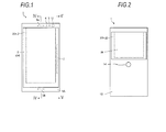
- FIG. 1 is a front view of the mobile phone 1.
- FIG. 2 is a rear view of the mobile phone 1.
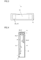
- FIG. 3 is a top view of the mobile phone 1.
- FIG. 4 is a cross-sectional view schematically illustrating a section IV-IV of the mobile phone 1.
- FIG. 5 is a cross-sectional view schematically illustrating a section V-V of the mobile phone 1.
- the mobile phone 1 has an illuminance sensor 4, a proximity sensor 5, a piezoelectric element 7, a first microphone 8a and a second microphone 8b, a camera 12, a panel 20a, and a touch screen 21, on its front surface (first surface) 1A.
- the mobile phone 1 has a camera 14, a panel 20b, and a touch screen 22, on its rear surface (second surface) 1B.
- the mobile phone 1 has a panel 20c and a touch screen 23, on its top surface (third surface) 1C.
- the mobile phone 1 has a structural design in which a large-sized display is arranged on the front surface of the device and the microphones are provided at symmetric positions of both ends in the longitudinal direction of a housing 40.
- the mobile phone 1 has little difference in appearance between a case where an end portion of the housing 40 on the first microphone (8a) side in the longitudinal direction is positioned upper and a case where an end portion of the housing 40 on the second microphone (8b) side in the longitudinal direction is positioned upper.
- a display 2 is a display device such as an organic EL device (OELD: Organic Electro-Luminescence Display) having flexibility. As shown in FIG. 4 , the display 2 is disposed inside the housing 40 in a state where it is bent. The display 2 displays characters, images, symbols, figures, and so on. The display 2 has a first display area 2a, a second display area 2b, and a third display area 2c. The display 2 can display the same information or different information in each of the first display area 2a, the second display area 2b, and the third display area 2c, according to control of a controller 10 to be described below.
- OELD Organic Electro-Luminescence Display
- the display 2 is controlled such that the display displays or does not display information in each of the first display area 2a, the second display area 2b, and the third display area 2c.
- Contents displayed in the first display area 2a can be viewed from the front surface (1A) side through the panel 20a and the touch screen 21.
- Contents displayed in the second display area 2b can be viewed from the rear surface (1B) side through the panel 20b and the touch screen 22.
- Contents displayed in the third display area 2c can be viewed from the top surface (1C) side through the panel 20c and the touch screen 23.
- the illuminance sensor 4 detects the illuminance of light around the mobile phone 1. Illuminance represents the intensity, brightness, or luminance of light. The illuminance sensor 4 is used, for example, to adjust the luminance of the display 2.
- the proximity sensor 5 detects the presence of a neighboring object in a non-contract manner. The proximity sensor 5 detects the presence of an object based on a change in a magnetic field, a change in the return time of the reflected wave of an ultrasonic wave, or the like. The proximity sensor 5 detects, for example, that the display 2 is close to a face.
- the illuminance sensor 4 and the proximity sensor 5 may be configured as one sensor. The illuminance sensor 4 may be used as a proximity sensor.
- the piezoelectric element 7 expands and contracts or bends according to the electromechanical coupling factor of its constituent material. That is, if an electric signal is applied, the piezoelectric element 7 deforms.
- the piezoelectric element 7 is attached to the panel 20a, and is used as a vibration source for vibrating the panel 20a.
- the piezoelectric element 7 is formed, for example, using ceramic or crystal.
- the piezoelectric element 7 may be a unimorph type, bimorph type, or laminated type piezoelectric element.
- a laminated type piezoelectric element includes a laminated type bimorph element which is a laminate of bimorphs (for example, a laminate of 16 layers or 24 layers).
- a laminated type piezoelectric element is composed of a plurality of dielectric layers consisting of, for example, PZT (lead zirconate titanate), and electrode layers interposed between the plurality of dielectric layers.
- the unimorph type expands and contracts if an electric signal (a voltage) is applied.
- the bimorph type bends if an electric signal (a voltage) is applied.
- the first microphone 8a and the second microphone 8b are sound input units.
- the first microphone 8a and the second microphone 8b convert input sound into electric signals and transmit the electric signals to the controller 10.
- the first microphone 8a and the second microphone 8b collect (input) a voice uttered from a user, for example, during a call.
- the camera 12 converts acquired images into electric signals and transmits the electric signals to the controller 10.
- Examples of the camera 12 include an in-camera which photographs objects facing the display 2, and an out-camera which photographs objects facing the opposite surface to the display 2.
- the panel 20a vibrates according to deformation (expansion and contraction or bending) of the piezoelectric element 7, and transmits that vibration to the cartilage (auricular cartilage) of an ear which the user brings into contact with the panel 20a.
- the panel 20a is formed of a synthetic resin such as glass or acrylate.
- the shape of the panel 20a is, for example, a plate shape.
- the panel 20a may be a flat plate.
- the panel 20a may be a curved panel whose surface is smoothly curved.
- the panel 20a may be a battery lid.
- the battery lid is a member which is attached to the housing 40 so as to cover a battery.
- the piezoelectric element 7 may be a component which vibrates a corner of the housing 40 (for example, at least one of four corners).
- the piezoelectric element 7 may be a component which is attached to the inner surface of the corner of the housing 40, or an intermediate member may be further provided such that vibration of the piezoelectric element 7 can be transmitted to the corner of the housing 40 through the intermediate member.
- an intermediate member may be further provided such that vibration of the piezoelectric element 7 can be transmitted to the corner of the housing 40 through the intermediate member.
- the display 2 and the piezoelectric element 7 are attached by a bonding member 30 (see FIG. 5 ).
- the piezoelectric element 7 is spaced apart from the inner surface of the housing 40 by a predetermined distance in a state where the piezoelectric element has been disposed on the rear surface of the panel 20a. It is preferable that the piezoelectric element 7 is spaced apart from the inner surface of the housing 40 even in a state where the piezoelectric element has expanded and contracted or bent. That is, it is preferable that a distance between the piezoelectric element 7 and the inner surface of the housing 40 is larger than the maximum deformation amount of the piezoelectric element 7.
- the piezoelectric element 7 may be attached to the panel 20a through a reinforcing member (for example, a metal plate or glass-fiber reinforced resin).
- the bonding member 30 is, for example, double-sided tape, or an adhesive having a thermosetting property, an ultraviolet-curing property, or the like.
- the bonding member 30 also may be a photoelastic resin which is a colorless and transparent ultraviolet-curable acrylic adhesive.
- the piezoelectric element 7 is arranged in the vicinity of a place spaced apart from an end portion in the short direction of the panel 20a by a predetermined distance such that the longitudinal direction of the piezoelectric element 7 becomes parallel to the longitudinal direction of the panel 20a (see FIG. 1 ).
- the center of the piezoelectric element 7 in the longitudinal direction is positioned on a straight line passing through the center of the panel 20a in the longitudinal direction and parallel to the short direction of the panel 20a.
- the piezoelectric element 7 may be attached to each of areas 7a, 7b, and 7c of the rear surface of the display 2, or may be attached to one or two of the areas 7a, 7b, and 7c.
- the display 2 to which the piezoelectric element 7 has been attached deforms according to expansion and contraction or bending of the piezoelectric element 7.
- a panel 20 to which the display 2 has been attached also deforms according to deformation of the display 2. In this case, if the user brings a part (auricular cartilage) of his body into contact with the panel 20, the panel 20 generates vibration sound (human body vibration sound) to be transmitted to the user through the part of his body.
- the panel 20b Since the panel 20b has a size which is almost a half of the size of the panel 20a, as compared to a case of attaching the piezoelectric element 7 to the area 7a, it is possible to reduce the area of the panel 20 to vibrate due to deformation of the piezoelectric element 7, and it is possible to reduce sound leakage.
- vibration which is generated by deformation of the piezoelectric element 7 is transmitted to the panel 20c through the display 2, whereby the panel 20c deforms.
- the panels 20a and 20b since vibration of the piezoelectric element 7 is transmitted even to both of the areas 7a and 7b connected to the area 7c of the display 2, the panels 20a and 20b also deform.
- the user can hear sound by putting an ear on any one surface of the front surface and rear surface of the mobile phone 1.
- the piezoelectric element 7 may be attached to an area which is included in the rear surfaces of the panels 20b and 20c and to which the display 2 has not been attached.
- the touch screen (touch sensor) 21 is arranged so as to overlap the display 2.
- the touch screen 21 detects contacts. Based on contacts which are detected by the touch screen 21, the controller 10 (the mobile phone 1) detects various operations (gestures) which are performed on the touch screen 21 by use of a finger, a stylus, a pen, or the like (hereinafter, referred to simply as a "finger").
- the touch screen 21 has a touch sensor.
- the touch sensor detects a contact of a finger with the touch screen 21 and the position of the contact point on the touch screen 21, and notifies them to the controller 10.
- the controller 10 detects operations (gestures) of the user on the surface of the display 2 by cooperating with the touch screen 21.
- Examples of various operations (gestures) which the controller 10 detects through the touch screen 21 include a touch, a long touch, a release, a swipe, a tap, a double tap, a long tap, a drag, a flick, a pinch-in, and a pinch-out, but are not limited thereto.
- the detection method of the touch screen 21 may be an arbitrary method such as an electrostatic capacity method, a resistance film method, a surface acoustic wave method (or an ultrasonic method), an infrared ray method, an electromagnetic induction method, and a load detection method.
- the display 2 and the touch screen 21 are functionally separated, but may be physically unified as a touch screen display.
- Contacts which are detected by the touch screen 21 include a contact of an auricle with the panel 20a, or the like.
- the touch screen 22 is arranged on the rear surface 1B of the mobile phone 1.
- the touch screen 22 has a size which is about a half of the size of the touch screen 21.
- the touch screen 23 is arranged on the top surface 1C of the mobile phone 1.
- the touch screen 22 detects contacts with the rear surface, and the touch screen 23 detects contacts with the top surface.
- the detection results of the touch screen 22 or the touch screen 23 are used to detect contact operations of the user using a finger, a pen, a stylus, or the like.
- Examples of operations (gestures) which are determined based on contacts which are detected using the touch screen 22 or the touch screen 23 include a touch, a long touch, a release, a swipe, a tap, a double tap, a long tap, a drag, a flick, a pinch-in, and a pinch-out, but are not limited thereto.
- the detection method of the touch screen 22 or the touch screen 23 may be any method such as an electrostatic capacity method, a resistance film method, a surface acoustic wave method (or an ultrasonic method), an infrared ray method, an electromagnetic induction method, and a load detection method.
- the detection method of the touch screen 22 or the touch screen 23 may be different from the detection method of the touch screen 21.
- the housing 40 is formed using a resin or a metal.
- the housing 40 supports the display 2, the illuminance sensor 4, the proximity sensor 5, the first microphone 8a, the second microphone 8b, the camera 12, the panel 20a, and so on.
- an electric signal according to sound to be output is applied.
- ⁇ 15 V which is higher than ⁇ 5 V being a supply voltage for a so-called panel speaker for transmitting sound by air-conducted sound through an external auditory canal may be applied. Accordingly, even in a case where the user presses a part of his body against the panel 20a, for example, with a force of 3 N or more (a force of 5 N to 10 N), the piezoelectric element 7 can cause the panel 20a to sufficiently vibrate, thereby generating vibration sound to be transmitted through the part of the body of the user.
- the voltage to be applied to the piezoelectric element 7 can be appropriately adjusted according to the fixing strength of the panel 20a to the housing 40, the performance of the piezoelectric element 7, or the like.
- the piezoelectric element 7 expands and contracts or bends in the longitudinal direction.
- the panel 20a to which the piezoelectric element 7 has been attached deforms according to the expansion and contraction or bending of the piezoelectric element 7. As a result, the panel 20a vibrates, thereby generating air-conducted sound. Further, in a case where the user brings a part (for example, an auricular cartilage) of his body, the panel 20a generates vibration sound to be transmitted to the user through the part of his body. That is, according to deformation of the piezoelectric element 7, the panel 20a vibrates at a frequency which can be perceived as vibration sound for an object being in contact with the panel 20a.
- a sound signal to be output through the piezoelectric element 7 and the panel 20a may be based on sound data stored in a storage 9 to be described below.
- a sound signal to be output through the piezoelectric element 7 and the panel 20a may be based on sound data stored in an external server or the like and acquired through a network by the communication unit 6 to be described below.
- the panel 20a may have almost the same size as that of an ear of the user. Also, the panel 20a may have a size larger than that of an ear of the user. In this case, on the occasion of hearing sound, the user can bring the substantially entire outer circumferential portion of an ear into contact with the panel 20a. The user hears sound in this way, and thus it is difficult for ambient sound (noise) to enter an external auditory canal.
- ambient sound noise
- the panel 20a vibrates in an area wider than an area having a longitudinal (or short) length corresponding to a distance from a lower antihelix crus (inferior antihelix crus) of a human being to an antitragus and a short (or longitudinal) length corresponding to a distance from a tragus to an antitragus.
- the panel 20a may vibrate in an area having a longitudinal (or short) length corresponding to a distance from a part in the vicinity of the upper antihelix crus (superior antihelix crus) of a helix to an ear lobe and a short (or longitudinal) length corresponding to a distance from a tragus to a part in the vicinity of the antihelix of the helix.
- the area having the length and the width described above may be a rectangular area, or may have an elliptical shape having the above described longitudinal length as a long diameter and the above described short length as a short diameter.
- the average size of human ears can be seen, for example, from Japanese Body Dimension Database (1992-1994) provided by the Research Institute of Human Engineering for Quality Life (HQL).
- the panel 20a vibrates not only in an attachment area 20a to which the piezoelectric element 7 has been attached, but also in an area spaced apart from the attachment area 20a.
- the panel 20a has a plurality of parts which is included in the vibration area and vibrates in a direction intersecting with a main surface of the panel 20a, and in each of the plurality of parts, the value of the amplitude of vibration varies from a positive value to a negative value, or vise versa with time.
- the panel 20a vibrates in such a manner that parts with relatively large vibration amplitude and parts with relatively small vibration amplitude are seemingly distributed randomly or regularly almost in the whole of the panel 20a. That is, over the entire panel 20a, vibrations of a plurality of waves are detected.
- the voltage which is applied to the piezoelectric element 7 is ⁇ 15 V as described above, even in a case where the user presses the panel 20a against the user's body, for example, with a force of 5 N to 10 N, it is difficult to damp the above described vibration of the panel 20a. Therefore, the user cannot hear vibration sound even if bringing an ear into contact with an area spaced apart from the attachment area 20a on the panel 20a.
- the mobile phone 1 can transmit air-conducted sound and vibration sound through a part (for example, auricular cartilage) of the body of the user, to the user. Therefore, in a case of outputting sound at the same volume as that of a dynamic receiver, the mobile phone 1 can reduce sound to be transmitted to the surroundings of the mobile phone 1 by vibration of air, as compared to an electronic device provided with only a dynamic speaker.
- This feature is suitable, for example, for a case of hearing a recorded message in a place where there is another person close to the user like on a train.
- the mobile phone 1 transmits vibration sound to the user by vibration of the panel 20a. Therefore, even when the user is wearing an earphone or a headphone on the body, the user can hear vibration sound attributable to vibration of the panel 20a, through either the earphone or the headphone, and a pat of the body, by bringing the mobile phone 1 into contact with them.
- the mobile phone 1 transmits sound by vibration of the panel 20a. Therefore, in a case where the mobile phone 1 does not separately have a dynamic receiver, it is unnecessary to form an opening (a sound emission opening) for transmitting sound which the panel 20a emits to the outside, in the housing 40. Therefore, in a case of implementing a waterproof structure, it is possible to simplify the structure.
- the mobile phone 1 may use a structure in which the opening is occluded by a member which allows passage of gas but does not allow passage of liquid.
- the member which allows passage of gas but does not allow passage of liquid is, for example, Gore-Tex (a registered trademark).
- the mobile phone 1 may have a speaker such as a dynamic speaker.
- FIG. 6 is a block diagram of the mobile phone 1 according to the embodiment.
- the mobile phone 1 includes the display 2, the illuminance sensor 4, the proximity sensor 5, the communication unit 6, the piezoelectric element 7, the first microphone 8a, the second microphone 8b, the storage 9, the controller 10, the camera 12, a vibration receiver 13 including the piezoelectric element 7 and the panel 20a, a posture detection unit 15, a vibrator 18, and the touch screen 21.
- the communication unit 6 performs communication in a wireless manner.
- Communication systems which can be supported by the communication unit 6 are wireless communication standards.
- the wireless communication standards there are cellular-phone communication standards such as 2G, 3G, and 4G.
- Examples of the cellular-phone communication standards include LTE (Long Term Evolution), W-CDMA (Wideband Code Division Multiple Access), CDMA 2000, PDC (Personal Digital Cellular), GSM (a registered trademark) (Global System for Mobile Communications), PHS (Personal Handy-phone System), and so on.
- Examples of the wireless communication standards further include WiMAX (Worldwide Interoperability for Microwave Access), IEEE 802.11, Bluetooth (a registered trademark), IrDA (Infrared Data Association), NFC (Near Field Communication), and so on.
- the communication unit 6 may support one or more of the above described communication standards.
- the storage 9 stores programs and data.
- the storage 9 is also used as a work area for temporarily storing process results of the controller 10.
- the storage 9 may include an arbitrary non-transitory storage medium such as a semiconductor storage medium and a magnetic storage medium.
- the storage 9 may include a plurality of types of storage media.
- the storage 9 may include a combination of a portable storage medium such as a memory card, an optical disc, or a magneto-optical disc with a storage medium reading device.
- the storage 9 may include a storage device which is used as a temporary storage area, such as a RAM (Random Access Memory).
- the programs which are stored in the storage 9 include applications which can be executed in the foreground or the background, and a control program which supports operations of the applications. In applications which can be executed in the foreground, for example, screens are displayed on the display 2.
- the control program includes, for example, an OS.
- the applications and the control program may be installed in the storage 9 through wireless communication of the communication unit 6 or a non-transitory storage medium.
- the storage 9 stores, for example, a control program 9A, a call application 9B, a music playback application 9C, a video playback application 9D, and setting data 9Z.
- the call application 9B provides a call function for calls using wireless communication.
- the music playback application 9C provides a music playback function for playing sound from music data.
- the video playback application 9D provides a video playback function for playing videos and sound from video data.
- the setting data 9Z includes various settings associated with operations of the mobile phone 1 and information relative to processes.
- Sound for example, a call voice
- the function which the call application 9B provides is output from the vibration receiver 13.
- the control program 9A provides a function relative to various control for operating the mobile phone 1.
- the control program 9A realizes a call, for example, by controlling the communication unit 6, the piezoelectric element 7, the first microphone 8a, the second microphone 8b, and so on.
- the function which the control program 9A provides may be used in combination with the function which another program such as the call application 9B provides.
- the function which the control program 9A provides includes a function of determining which of the first microphone 8a and the second microphone 8b will be used, during a call.
- the control program 9A includes a function of determining which of the first microphone 8a and the second microphone 8b will be used, during a call, based on a detection result of the posture detection unit 15.
- the controller 10 is an arithmetic processing unit. Examples of the arithmetic processing unit include a CPU (Central Processing Unit), an SoC (System-on-a-Chip), an MCU (Micro Control Unit), and an FPGA (Field-Programmable Gate Array), but are not limited thereto.
- the controller 10 generally controls operations of the mobile phone 1, thereby implementing various functions.
- the controller 10 performs commands included in programs stored in the storage 9 while referring to data stored in the storage 9 if necessary. Then, the controller 10 controls functional units according to the data and the commands, thereby implementing various functions. Examples of the functional units include the display 2, the communication unit 6, the piezoelectric element 7, the first microphone 8a, the second microphone 8b, and the vibrator 18, but are not limited thereto.
- the controller 10 may change control in response to detection results of detecting units. Examples of the detecting units include the illuminance sensor 4, the proximity sensor 5, the camera 12, the posture detection unit 15, and the touch screen 21, but are not limited thereto.
- the controller 10 executes, the control program 9A, thereby performing a process of determining which of the first microphone 8a and the second microphone 8b will be used during a call. For example, the controller 10 determines which of the first microphone 8a and the second microphone 8b will be used, during a call, based on a detection result of the posture detection unit 15.
- the vibration receiver 13 generates, for example, air-conducted sound and vibration sound corresponding to a call voice, and transmits them to the user.
- the posture detection unit 15 detects a posture of the mobile phone 1.
- the posture detection unit 15 includes at least one of an acceleration sensor, a direction sensor, and a gyroscope.
- the posture detection unit 15 measures an angle ( ⁇ ) which the housing 40 of the mobile phone 1 forms, for example, with respect to the acceleration of gravity (g), for example, based on the detection results of the acceleration sensor, the direction sensor and the gyroscope, and transmits the angle to the controller 10.
- the vibrator 18 vibrates a part of or the whole of the mobile phone 1.
- the vibrator 18 has, for example, a piezoelectric element or an eccentric motor. Vibration which is generated by the vibrator 18 is used to notify various events such as an incoming call to the user.
- a part or all of the programs and the data which the storage 9 stores in FIG. 6 may be downloaded from another device by wireless communication of the communication unit 6.
- a part or all of the programs and the data which the storage 9 stores in FIG. 5 may be stored in a non-transitory storage medium which a reading device included in the storage 9 can read.
- the non-transitory storage medium include an optical disc such as CD (a registered trademark), DVD (a registered trademark), or Blu-ray (a registered trademark), a magneto-optical disc, a magnetic storage medium, a memory card, and a solid-state storage medium, but are not limited thereto.
- the configuration of the mobile phone 1 shown in FIG. 6 is an example and may be appropriately modified in a range which does not depart from the gist of the present invention.
- the mobile phone 1 may have buttons of a ten-key arrangement, a QWERTY arrangement, or the like, as buttons for operations.
- FIG. 7 is a view illustrating display modes in the plurality of display areas of the display 2.
- the mobile phone 1 can switch which of the first display area 2a, the second display area 2b, and the third display area 2c of the display 2 displays predetermined information, based on the detection result of the illuminance sensor 4, the detection result of the proximity sensor 5, and the detection result of the posture detection unit 15.
- the controller 10 controls display of each of the first display area 2a, the second display area 2b, and the third display area 3c of the display 2, based on the detection result of the illuminance sensor 4, the detection result of the proximity sensor 5, and the posture of the mobile phone 1 detected by the posture detection unit 15.
- the mobile phone 1 displays predetermined information (here, information on date and time) in the third display area 3c. Due to this control, for example, in a case where the mobile phone 1 is in a breast pocket in a state where the user is standing upright, the user can confirm the information on date and time without taking the mobile phone 1 out of the breast pocket.
- predetermined information here, information on date and time
- the posture detection unit 15 can detect which of the first display area 2a and the second display area 2b is positioned relatively higher, and based on the corresponding detection result, the mobile phone 1 can display information on date and time in one display area positioned relatively higher. That is, the mobile phone 1 displays information on date and time in the first display area 2a as shown in FIG. 7B , in a case where the first display area 2a is positioned upper than the second display area 2b, and displays information on date and time in the second display area 2b as shown in FIG. 7C , in a case where the second display area 2b is positioned upper than the first display area 2a.
- display of information in the other display areas may not be performed. Display of information in a display area less likely to be viewed by the user is not performed, whereby it is possible to reduce electric power which is consumed in the mobile phone 1.
- the controller 10 controls which of the plurality of display areas of the display 2 displays information, based on the detection result of the illuminance sensor 4, the detection result of the proximity sensor 5, and the posture of the mobile phone 1 detected by the posture detection unit 15.
- the controller 10 may determine the state of the mobile phone 1 based on an image which is acquired by the camera 12 or the camera 14 and control which display area of the plurality of display areas of the display 2 displays information, based on the corresponding determination result, or the controller 10 may determine the state of the mobile phone 1 based on the detection results of the illuminance sensor 4, the proximity sensor 5 and the posture detection unit 15 as well.
- the posture detection unit 15 detects that the second display area 2b is positioned upper than the first display area 2a, if the face of the user is detected by the camera 12, the mobile phone 1 may display information in the first display area 2a positioned relatively lower. Therefore, for example, in a case where the user operates the mobile phone 1 in a state where the user is lying on his back, since information is displayed in the first display area 2a which the user is viewing, the user does not feel inconvenience.
- a touch sensor (not shown) may be arranged on a side of the mobile phone 1, and the contact detection result of the touch sensor may be added to the criteria.
- the mobile phone 1 can simultaneously display the same information or different information in each of the first display area 2a, the second display area 2b, and the third display area 2c of the display 2, according to control of the controller 10. Display control of the mobile phone 1 in this case will be described using FIGS. 8 to 11 .
- FIG. 8 is a view illustrating a first example of display control in the plurality of display areas of the display 2.
- FIG. 8A is a view illustrating the third display area 2c provided on the top surface 1C of the mobile phone 1, as viewed from the above.
- the upper side of the drawing is the rear surface (1B) side
- the lower side of the drawing is the front surface (1A) side.
- the positional relation between the front surface 1A and the rear surface 1B in each view illustrating the third display area 3c is considered as being identical to that in FIG. 8A unless otherwise mentioned.
- the third display area 2c As shown in FIG. 8A , at the right end portion of the third display area 2c, there is displayed a mail icon consisting of an envelope picture and a number "1".
- the mail icon represents that there is one unread mail.
- the third display area 2c is used as an indicator area. Further, the user performs a flick in a direction from the top surface 1C, as starting point, toward the front surface 1A (an arrow direction of the drawing), on the mail icon displayed in the third display area 2c, with a finger.
- FIG. 8B is a view illustrating a transition between screens which are displayed in the first display area 2a before and after a flick on the mail icon is performed as shown in FIG. 8A .
- a home screen is displayed in the first display area 2a, as shown on the left of FIG. 8B .
- the flick is performed as shown on the right of FIG. 8B , the contents of the unread mail is displayed in the first display area 2a.
- FIGS. 8A and 8B The display control shown in FIGS. 8A and 8B will be described in detail.
- the controller 10 of the mobile phone 1 displays the home screen in the first display area 2a. Then, the controller 10 detects a flick in the direction from the top surface 1C toward the front surface 1A, on the mail icon displayed in the third display area 2c, through the touch screen 23 provided on the top surface 1C of the mobile phone 1. When detecting a flick in the direction from the top surface 1C toward the front surface 1A on the mail icon, the controller 10 displays the contents of the unread mail which is information corresponding to the mail icon, in the first display area 2a of the front surface (1A) side of the mobile phone 1.
- FIG. 9 is a view illustrating a second example of display control in the plurality of display areas of the display 2.
- a mail icon representing that there is one unread mail is displayed in the third display area 2c.
- the user performs a flick in a direction from the top surface 1C, as starting point, toward the rear surface 1B (an arrow direction of the drawing), on the mail icon displayed in the third display area 2c, with a finger.
- the flick direction shown in FIG. 9A is the opposite direction to the flick direction shown in FIG. 8A .
- FIG. 9B is a view illustrating a transition between screens which are displayed in the second display area 2b before and after the flick on the mail icon is performed as shown in FIG. 9A .
- a particular thing is not displayed in the second display area 2b.
- the flick is performed, as shown on the right of FIG. 9B , the contents of the unread mail is displayed in the second display area 2b.
- the controller 10 of the mobile phone 1 detects a flick in the direction from the top surface 1C toward the rear surface 1B, on the mail icon displayed in the third display area 2c, through the touch screen 23 provided on the top surface 1C of the mobile phone 1. If detecting a flick in the direction from the top surface 1C toward the rear surface 1B, on the mail icon, the controller 10 displays the contents of the unread mail which is information corresponding to the mail icon, in the second display area 2b of the rear surface (1B) side of the mobile phone 1.
- the area of the second display area 2b is smaller than that of the first display area 2a. Therefore, in a case of displaying the contents of the unread mail in the second display area 2b, the controller 10 may reduce the size of characters such that all of the contents of the unread mail are displayed in the second display area 2b.
- FIG. 10 is a view illustrating a third example of display control in the plurality of display areas of the display 2.
- a mail icon representing that there is one unread mail, similarly to FIG. 8A .
- a game icon which is an icon associated with a game application and has the shape of an alphabet "G”.
- an icon which is an icon associated with a retrieval application and has the shape of a magnifying glass.
- the user performs a flick in a direction from the top surface 1C, as a starting point, toward the front surface 1A, on the game icon displayed in the third display area 2c, with a finger.
- another user or the same user performs a flick in a direction from the top surface 1C, as a starting point, toward the rear surface 1B, on the mail icon displayed in the third display area 2c, with a finger.
- a game application screen is displayed in the first display area 2a while an unread mail screen is displayed in the second display area 2b.
- FIG. 10 Screen control of the controller 10 in FIG. 10 is the same as that in the first example shown in FIG. 8 and that in the second example shown in FIG. 9 .
- the individual flicks in FIG. 10A may be performed simultaneously.
- the controller 10 may give priority, for example, to the flick in the direction from the top surface 1C, as a starting point, toward the front surface 1A, of the individual flicks which are detected through the touch screen 23 to display the game screen in the first display area 2a, and then display the unread mail screen in the second display area 2b.
- FIG. 11 is a view illustrating a fourth example of display control in the plurality of display areas of the display 2.
- a camera icon corresponding to a camera application.
- a flick in a direction from the top surface 1C, as a starting point, toward the front surface 1A is performed on the camera icon
- a camera finder screen is displayed in the first display area 2a.
- a flick in a direction from the top surface 1C, as a starting point, toward the rear surface 1B is performed on the camera icon
- a camera finder screen is displayed in the second display area 2b.
- the mobile phone 1 of the present embodiment performs imaging by the camera 13 in a state shown in FIG. 11A , and performs imaging by the camera 12 in a state shown in FIG. 11B .
- the mobile phone 1 can use both of the first display area 2a and the second display area 2b as camera finders. Therefore, in a case of using the first display area 2a as a camera finder as shown in FIG. 11A , if a tap of the user is detected through the touch screen 22 of the rear surface (1 B) side, the mobile phone 1 may perform imaging.
- the mobile phone 1 may perform imaging. Therefore, in a case where the user is gripping the mobile phone 1 with one hand, it is possible to perform imaging by tapping the touch screen 21 or the touch screen 22 with a finger of the gripping hand, without using the other hand, and thus usability is improved.
- the camera 14 is provided in the vicinity of the center in the longitudinal direction of the rear surface 1B so as to be adjacent to the panel 20b (and the second display area 2b) on the rear surface 1B. Therefore, in a case where the user turns the rear surface (1B) side toward himself and uses the camera 14 to attempt imaging of his posture reflected in the second display area 2b, the camera 14 is positioned in front of his face such that it is possible to perform imaging while viewing the second display area 2b serving as a finder, and thus usability is further improved.
- FIG. 12 is a view illustrating a first example of control according to a gesture on the third display area 2c.
- FIG. 12B shows a state where the user is performing a call by the call application.
- the user performs a swipe in a direction from the left toward the right on the third display area 2c. If detecting the swipe in the direction from the left toward the right on the third display area 2c through the touch screen 23, the controller 10 of the mobile phone 1 makes the volume of call sound relatively large. On the contrary, if detecting a swipe from the right toward the left on the third display area 2c through the touch screen 23, the controller 10 makes the volume of call sound relatively small.
- FIG. 13 is a view illustrating a second example of control according to a gesture on the third display area 2c.
- the mobile phone 1 In a state shown in FIG. 13A , the mobile phone 1 is in a locked state. Then, at the central portion of the third display area 2c, an unlocking icon is displayed. Then, the user performs a flick in a direction from the top surface 1C, as a starting point, toward the front surface 1A, on the unlocking icon displayed in the third display area 2c, with a finger.
- the controller 10 of the mobile phone 1 releases the locking of the mobile phone 1 and then displays the home screen in the first display area 2a of the front surface (1A) side.
- the mobile phone 1 includes the touch screen 23 on the top surface 1C connecting the front surface 1A and the rear surface 1B of the mobile phone. If a flick (a first gesture) in the direction from the top surface 1C toward the front surface 1A is detected through the touch screen 23, the mobile phone displays a screen according to the corresponding flick in the first display area 2a of the front surface (1A) side. Also, if a flick (a second gesture) in the direction from the top surface 1C toward the rear surface 1B is detected, the mobile phone displays a screen according to the corresponding flick in the second display area 2b of the rear surface (1B) side. Therefore, the usability of the mobile phone 1 is improved.
- the mobile phone 1 controls display of the third display area 2c, in response to the posture of the mobile phone 1. Therefore, effective utilization of the third display area 2c provided on the top surface 1C of the housing 40 is achieved.
- the indicator area is displayed in the first display area 2a.
- the third display area 2c provided on the top surface 1C of the mobile phone 1 is used as the indicator area, effective utilization of the first display area 2a is achieved.
- the mobile phone has been described.
- the device according to the appended claims is not limited to the mobile phone.
- the device according to the appended claims may be an electronic device other than the mobile phone.
- the electronic device include, for example, tablets, portable personal computers, digital cameras, media players, electronic book readers, navigators, and game consoles, but are not limited thereto.
- the mobile phone 1 may have a configuration in which separate displays (display units) and touch screens are provided on the front surface 1A, the rear surface 1B, and the top surface 1C, respectively.
- the touch screen 21, the touch screen 22, and the touch screen 23 are disposed corresponding to the first display area 2a, the second display area 2b, and the third display area 2c, respectively.
- the present invention is not limited thereto.
- the mobile phone 1 may not have the touch screen 21 which is disposed on the front surface 1A and the touch screen 22 which is disposed on the rear surface 1B, or may not have the third display area 2c which is disposed on the top surface 1C.
Landscapes
- Engineering & Computer Science (AREA)
- Theoretical Computer Science (AREA)
- General Engineering & Computer Science (AREA)
- Human Computer Interaction (AREA)
- Physics & Mathematics (AREA)
- General Physics & Mathematics (AREA)
- Computer Hardware Design (AREA)
- Telephone Function (AREA)
- Digital Computer Display Output (AREA)
- User Interface Of Digital Computer (AREA)
- Telephone Set Structure (AREA)
Abstract
Description
- The present invention relates to a device provided with a touch screen display.
- There is a known device provided with a touch screen display. Examples of the device provided with the touch screen display include smart phones and tablets. The device provided with the touch screen display detects a gesture of fingers or a stylus pen through the touch screen display. Then, the device provided with the touch screen display operates according to the detected gesture. Examples of an operation according to a detected gesture are described in
Patent Literature 1 for instance. - A basic operation of the device provided with the touch screen display is realized by OS (Operating System) of Android (a registered trademark), BlackBerry (a registered trademark) OS, Symbian (a registered trademark) OS, iOS, or Windows (a registered trademark) Phone or the like.
- Patent Literature 1:
WO 2008/086302 - However, improving of operability was required in the above described device.
- An object of the present invention is to provide a device having improved operability.
- A device according to an aspect of the present invention includes: a housing that has a first surface, a second surface, and a third surface connecting the first surface and the second surface; a touch screen that is disposed on the third surface of the housing; at least one display that is a display, which is disposed inside the housing and has a first display area performing display on the first surface and a second display area performing display on the second surface; and a controller that displays a screen according to a first operation in the first display area if the first operation is detected by the touch screen of the third surface, and displays a screen according to a second operation different from the first operation in the second display area if the second operation is detected by the touch screen of the third surface.
- In the device according to the aspect described above, the first operation may be a first gesture operation from the third surface toward the first surface, and the second operation may be a second gesture operation from the third surface toward the second surface.
- In the device according to the aspect described above, the first operation and the second operation may be operations on the same icon on the touch screen.
- In the device according to the aspect described above, the controller may change the volume of call sound in response to a swipe operation on the touch screen of the third surface.
- In the device according to the aspect described above, the display may be one flexible display, and the flexible display may have the first display area and the second display area.
- A device according to another aspect of the present invention includes: a housing that has a first surface, a second surface, and a third surface connecting the first surface and the second surface; a display that is a flexible display, which is disposed inside the housing, and has a first display area performing display on the first surface, a second display area performing display on the second surface and a third display area performing display on the third surface; a posture detection unit that detects a posture; and a controller that controls display of the third display area in response to the posture detected by the posture detection unit.
- The device according to the aspect described above may include a proximity sensor that determines whether it is close to an object, and in a case where the posture detected by the posture detection unit is in a vertical direction and the proximity sensor determines that it is close to an object, the controller may control the third display area such that the third display area displays predetermined information.
- In the device according to the aspect described above, the posture detection unit may detect whether one of the first display area and the second display area is positioned upper than the other of the first display area and the second display area, and the controller may display predetermined information in the one of the first display area and the second display area positioned upper than the other.
- A device according to another aspect of the present invention includes: a housing; a panel that is a panel, which is attached to the housing and has a first surface, a second surface, and a third surface connecting the first surface and the second surface; a display that is a display, which is attached to the panel and has a first display area performing display on the first surface, a second display area performing display on the second surface and a third display area performing display on the third surface; and a piezoelectric element that is attached to the display, wherein the panel deforms due to deformation of the piezoelectric element, thereby transmitting human body vibration sound to an object.
- According to the present invention, it is possible to provide a device having improved operability.
-
-
FIG. 1 is a front view of a mobile phone. -
FIG. 2 is a rear view of the mobile phone. -
FIG. 3 is a top view of the mobile phone. -
FIG. 4 is a cross-sectional view schematically illustrating a section IV-IV of the mobile phone. -
FIG. 5 is a cross-sectional view schematically illustrating a section V-V of the mobile phone. -
FIG. 6 is a block diagram of a mobile phone according to an embodiment. -
FIGS. 7A, 7B, and 7C are views illustrating display modes in a plurality of display areas of a display. -
FIGS. 8A and 8B are views illustrating a first example of display control in the plurality of display areas of the display. -
FIGS. 9A and 9B are views illustrating a second example of display control in the plurality of display areas of the display. -
FIGS. 10A and 10B are views illustrating a third example of display control in the plurality of display areas of the display. -
FIGS. 11A and 11B are views illustrating a fourth example of display control in the plurality of display areas of the display. -
FIGS. 12A and 12B are views illustrating a first example of control according to a gesture on a third display area. -
FIGS. 13A and 13B are views illustrating a second example of control according to a gesture on the third display area. - An embodiment for implementing a device according to this application will be described in detail with reference to drawings. Hereinafter, as an example of a device according to an embodiment, a mobile phone will be described.
- With reference to
FIGS. 1 to 5 , the overall configuration of amobile phone 1 according to an embodiment will be described.FIG. 1 is a front view of themobile phone 1.FIG. 2 is a rear view of themobile phone 1.FIG. 3 is a top view of themobile phone 1.FIG. 4 is a cross-sectional view schematically illustrating a section IV-IV of themobile phone 1.FIG. 5 is a cross-sectional view schematically illustrating a section V-V of themobile phone 1. - As shown in
FIG. 1 , themobile phone 1 has anilluminance sensor 4, aproximity sensor 5, apiezoelectric element 7, afirst microphone 8a and asecond microphone 8b, acamera 12, apanel 20a, and atouch screen 21, on its front surface (first surface) 1A. - As shown in
FIG. 2 , themobile phone 1 has acamera 14, apanel 20b, and atouch screen 22, on its rear surface (second surface) 1B. - As shown in
FIG. 3 , themobile phone 1 has apanel 20c and atouch screen 23, on its top surface (third surface) 1C. - As shown in
FIG. 1 , themobile phone 1 has a structural design in which a large-sized display is arranged on the front surface of the device and the microphones are provided at symmetric positions of both ends in the longitudinal direction of ahousing 40. Themobile phone 1 has little difference in appearance between a case where an end portion of thehousing 40 on the first microphone (8a) side in the longitudinal direction is positioned upper and a case where an end portion of thehousing 40 on the second microphone (8b) side in the longitudinal direction is positioned upper. - A
display 2 is a display device such as an organic EL device (OELD: Organic Electro-Luminescence Display) having flexibility. As shown inFIG. 4 , thedisplay 2 is disposed inside thehousing 40 in a state where it is bent. Thedisplay 2 displays characters, images, symbols, figures, and so on. Thedisplay 2 has afirst display area 2a, asecond display area 2b, and athird display area 2c. Thedisplay 2 can display the same information or different information in each of thefirst display area 2a, thesecond display area 2b, and thethird display area 2c, according to control of acontroller 10 to be described below. According to control of the controller 10 (to be described below), thedisplay 2 is controlled such that the display displays or does not display information in each of thefirst display area 2a, thesecond display area 2b, and thethird display area 2c. Contents displayed in thefirst display area 2a can be viewed from the front surface (1A) side through thepanel 20a and thetouch screen 21. Contents displayed in thesecond display area 2b can be viewed from the rear surface (1B) side through thepanel 20b and thetouch screen 22. Contents displayed in thethird display area 2c can be viewed from the top surface (1C) side through thepanel 20c and thetouch screen 23. - The
illuminance sensor 4 detects the illuminance of light around themobile phone 1. Illuminance represents the intensity, brightness, or luminance of light. Theilluminance sensor 4 is used, for example, to adjust the luminance of thedisplay 2. Theproximity sensor 5 detects the presence of a neighboring object in a non-contract manner. Theproximity sensor 5 detects the presence of an object based on a change in a magnetic field, a change in the return time of the reflected wave of an ultrasonic wave, or the like. Theproximity sensor 5 detects, for example, that thedisplay 2 is close to a face. Theilluminance sensor 4 and theproximity sensor 5 may be configured as one sensor. Theilluminance sensor 4 may be used as a proximity sensor. - If an electric signal (a voltage according to a sound signal) is applied, the
piezoelectric element 7 expands and contracts or bends according to the electromechanical coupling factor of its constituent material. That is, if an electric signal is applied, thepiezoelectric element 7 deforms. Thepiezoelectric element 7 is attached to thepanel 20a, and is used as a vibration source for vibrating thepanel 20a. Thepiezoelectric element 7 is formed, for example, using ceramic or crystal. Thepiezoelectric element 7 may be a unimorph type, bimorph type, or laminated type piezoelectric element. A laminated type piezoelectric element includes a laminated type bimorph element which is a laminate of bimorphs (for example, a laminate of 16 layers or 24 layers). A laminated type piezoelectric element is composed of a plurality of dielectric layers consisting of, for example, PZT (lead zirconate titanate), and electrode layers interposed between the plurality of dielectric layers. The unimorph type expands and contracts if an electric signal (a voltage) is applied. The bimorph type bends if an electric signal (a voltage) is applied. - The
first microphone 8a and thesecond microphone 8b are sound input units. Thefirst microphone 8a and thesecond microphone 8b convert input sound into electric signals and transmit the electric signals to thecontroller 10. Thefirst microphone 8a and thesecond microphone 8b collect (input) a voice uttered from a user, for example, during a call. - The
camera 12 converts acquired images into electric signals and transmits the electric signals to thecontroller 10. Examples of thecamera 12 include an in-camera which photographs objects facing thedisplay 2, and an out-camera which photographs objects facing the opposite surface to thedisplay 2. - The
panel 20a vibrates according to deformation (expansion and contraction or bending) of thepiezoelectric element 7, and transmits that vibration to the cartilage (auricular cartilage) of an ear which the user brings into contact with thepanel 20a. Thepanel 20a is formed of a synthetic resin such as glass or acrylate. The shape of thepanel 20a is, for example, a plate shape. Thepanel 20a may be a flat plate. Thepanel 20a may be a curved panel whose surface is smoothly curved. Thepanel 20a may be a battery lid. The battery lid is a member which is attached to thehousing 40 so as to cover a battery. Thepiezoelectric element 7 may be a component which vibrates a corner of the housing 40 (for example, at least one of four corners). In this case, thepiezoelectric element 7 may be a component which is attached to the inner surface of the corner of thehousing 40, or an intermediate member may be further provided such that vibration of thepiezoelectric element 7 can be transmitted to the corner of thehousing 40 through the intermediate member. According to this configuration, since it is possible to make a vibration range relatively narrow, it is difficult for air-conducted sound which is generated by vibration to leak to the surroundings. Also, according to this configuration, for example, in a state where the user has inserted the corner of thehousing 40 into an external auditory canal, air-conducted tone and vibration sound are transmitted to the user. Therefore, it is difficult for ambient noise to enter the external auditory canal of the user. As a result, it is possible to improve the quality of sound to be transmitted to the user. - On the rear surface of the
panel 20a, thedisplay 2 and thepiezoelectric element 7 are attached by a bonding member 30 (seeFIG. 5 ). Thepiezoelectric element 7 is spaced apart from the inner surface of thehousing 40 by a predetermined distance in a state where the piezoelectric element has been disposed on the rear surface of thepanel 20a. It is preferable that thepiezoelectric element 7 is spaced apart from the inner surface of thehousing 40 even in a state where the piezoelectric element has expanded and contracted or bent. That is, it is preferable that a distance between thepiezoelectric element 7 and the inner surface of thehousing 40 is larger than the maximum deformation amount of thepiezoelectric element 7. Thepiezoelectric element 7 may be attached to thepanel 20a through a reinforcing member (for example, a metal plate or glass-fiber reinforced resin). The bondingmember 30 is, for example, double-sided tape, or an adhesive having a thermosetting property, an ultraviolet-curing property, or the like. The bondingmember 30 also may be a photoelastic resin which is a colorless and transparent ultraviolet-curable acrylic adhesive. - The
piezoelectric element 7 is arranged in the vicinity of a place spaced apart from an end portion in the short direction of thepanel 20a by a predetermined distance such that the longitudinal direction of thepiezoelectric element 7 becomes parallel to the longitudinal direction of thepanel 20a (seeFIG. 1 ). The center of thepiezoelectric element 7 in the longitudinal direction is positioned on a straight line passing through the center of thepanel 20a in the longitudinal direction and parallel to the short direction of thepanel 20a. - Also, in the present embodiment, the
piezoelectric element 7 may be attached to each ofareas display 2, or may be attached to one or two of theareas display 2 to which thepiezoelectric element 7 has been attached deforms according to expansion and contraction or bending of thepiezoelectric element 7. Also, apanel 20 to which thedisplay 2 has been attached also deforms according to deformation of thedisplay 2. In this case, if the user brings a part (auricular cartilage) of his body into contact with thepanel 20, thepanel 20 generates vibration sound (human body vibration sound) to be transmitted to the user through the part of his body. In a case where thepiezoelectric element 7 has been attached to thearea 7a, vibration which is generated by deformation of thepiezoelectric element 7 is transmitted to thepanel 20a through thedisplay 2, whereby thepanel 20a deforms. Since thepanel 20a has almost the same size as that of the front surface of themobile phone 1, for example, in an area larger than an ear of the user, it is easy to generate vibration of thepanel 20. In a case where thepiezoelectric element 7 has been attached to thearea 7b, vibration which is generated by deformation of thepiezoelectric element 7 is transmitted to thepanel 20b through thedisplay 2, whereby thepanel 20b deforms. Since thepanel 20b has a size which is almost a half of the size of thepanel 20a, as compared to a case of attaching thepiezoelectric element 7 to thearea 7a, it is possible to reduce the area of thepanel 20 to vibrate due to deformation of thepiezoelectric element 7, and it is possible to reduce sound leakage. In a case where thepiezoelectric element 7 has been attached to thearea 7c, vibration which is generated by deformation of thepiezoelectric element 7 is transmitted to thepanel 20c through thedisplay 2, whereby thepanel 20c deforms. In this case, since vibration of thepiezoelectric element 7 is transmitted even to both of theareas area 7c of thedisplay 2, thepanels mobile phone 1. Also, thepiezoelectric element 7 may be attached to an area which is included in the rear surfaces of thepanels display 2 has not been attached. - The touch screen (touch sensor) 21 is arranged so as to overlap the
display 2. Thetouch screen 21 detects contacts. Based on contacts which are detected by thetouch screen 21, the controller 10 (the mobile phone 1) detects various operations (gestures) which are performed on thetouch screen 21 by use of a finger, a stylus, a pen, or the like (hereinafter, referred to simply as a "finger"). For example, thetouch screen 21 has a touch sensor. The touch sensor detects a contact of a finger with thetouch screen 21 and the position of the contact point on thetouch screen 21, and notifies them to thecontroller 10. Thecontroller 10 detects operations (gestures) of the user on the surface of thedisplay 2 by cooperating with thetouch screen 21. Examples of various operations (gestures) which thecontroller 10 detects through thetouch screen 21 include a touch, a long touch, a release, a swipe, a tap, a double tap, a long tap, a drag, a flick, a pinch-in, and a pinch-out, but are not limited thereto. The detection method of thetouch screen 21 may be an arbitrary method such as an electrostatic capacity method, a resistance film method, a surface acoustic wave method (or an ultrasonic method), an infrared ray method, an electromagnetic induction method, and a load detection method. As shown inFIG. 1 , thedisplay 2 and thetouch screen 21 are functionally separated, but may be physically unified as a touch screen display. - Contacts which are detected by the
touch screen 21 include a contact of an auricle with thepanel 20a, or the like. - The
touch screen 22 is arranged on therear surface 1B of themobile phone 1. In the present embodiment, thetouch screen 22 has a size which is about a half of the size of thetouch screen 21. Thetouch screen 23 is arranged on the top surface 1C of themobile phone 1. - The
touch screen 22 detects contacts with the rear surface, and thetouch screen 23 detects contacts with the top surface. The detection results of thetouch screen 22 or thetouch screen 23 are used to detect contact operations of the user using a finger, a pen, a stylus, or the like. Examples of operations (gestures) which are determined based on contacts which are detected using thetouch screen 22 or thetouch screen 23 include a touch, a long touch, a release, a swipe, a tap, a double tap, a long tap, a drag, a flick, a pinch-in, and a pinch-out, but are not limited thereto. The detection method of thetouch screen 22 or thetouch screen 23 may be any method such as an electrostatic capacity method, a resistance film method, a surface acoustic wave method (or an ultrasonic method), an infrared ray method, an electromagnetic induction method, and a load detection method. The detection method of thetouch screen 22 or thetouch screen 23 may be different from the detection method of thetouch screen 21. - The
housing 40 is formed using a resin or a metal. Thehousing 40 supports thedisplay 2, theilluminance sensor 4, theproximity sensor 5, thefirst microphone 8a, thesecond microphone 8b, thecamera 12, thepanel 20a, and so on. - To the
piezoelectric element 7, an electric signal according to sound to be output is applied. To thepiezoelectric element 7, for example, ±15 V which is higher than ±5 V being a supply voltage for a so-called panel speaker for transmitting sound by air-conducted sound through an external auditory canal may be applied. Accordingly, even in a case where the user presses a part of his body against thepanel 20a, for example, with a force of 3 N or more (a force of 5 N to 10 N), thepiezoelectric element 7 can cause thepanel 20a to sufficiently vibrate, thereby generating vibration sound to be transmitted through the part of the body of the user. The voltage to be applied to thepiezoelectric element 7 can be appropriately adjusted according to the fixing strength of thepanel 20a to thehousing 40, the performance of thepiezoelectric element 7, or the like. - If an electric signal is applied, the
piezoelectric element 7 expands and contracts or bends in the longitudinal direction. Thepanel 20a to which thepiezoelectric element 7 has been attached deforms according to the expansion and contraction or bending of thepiezoelectric element 7. As a result, thepanel 20a vibrates, thereby generating air-conducted sound. Further, in a case where the user brings a part (for example, an auricular cartilage) of his body, thepanel 20a generates vibration sound to be transmitted to the user through the part of his body. That is, according to deformation of thepiezoelectric element 7, thepanel 20a vibrates at a frequency which can be perceived as vibration sound for an object being in contact with thepanel 20a. - For example, if an electric signal according to sound data such as the voice of the other party of a call, or a ring tone, or music is applied to the
piezoelectric element 7, thepanel 20a generates air-conducted sound and vibration sound corresponding to the electric signal. A sound signal to be output through thepiezoelectric element 7 and thepanel 20a may be based on sound data stored in astorage 9 to be described below. A sound signal to be output through thepiezoelectric element 7 and thepanel 20a may be based on sound data stored in an external server or the like and acquired through a network by the communication unit 6 to be described below. - In the present embodiment, the
panel 20a may have almost the same size as that of an ear of the user. Also, thepanel 20a may have a size larger than that of an ear of the user. In this case, on the occasion of hearing sound, the user can bring the substantially entire outer circumferential portion of an ear into contact with thepanel 20a. The user hears sound in this way, and thus it is difficult for ambient sound (noise) to enter an external auditory canal. In the present embodiment, at least, thepanel 20a vibrates in an area wider than an area having a longitudinal (or short) length corresponding to a distance from a lower antihelix crus (inferior antihelix crus) of a human being to an antitragus and a short (or longitudinal) length corresponding to a distance from a tragus to an antitragus. Thepanel 20a may vibrate in an area having a longitudinal (or short) length corresponding to a distance from a part in the vicinity of the upper antihelix crus (superior antihelix crus) of a helix to an ear lobe and a short (or longitudinal) length corresponding to a distance from a tragus to a part in the vicinity of the antihelix of the helix. The area having the length and the width described above may be a rectangular area, or may have an elliptical shape having the above described longitudinal length as a long diameter and the above described short length as a short diameter. The average size of human ears can be seen, for example, from Japanese Body Dimension Database (1992-1994) provided by the Research Institute of Human Engineering for Quality Life (HQL). - The
panel 20a vibrates not only in anattachment area 20a to which thepiezoelectric element 7 has been attached, but also in an area spaced apart from theattachment area 20a. Thepanel 20a has a plurality of parts which is included in the vibration area and vibrates in a direction intersecting with a main surface of thepanel 20a, and in each of the plurality of parts, the value of the amplitude of vibration varies from a positive value to a negative value, or vise versa with time. At each moment, thepanel 20a vibrates in such a manner that parts with relatively large vibration amplitude and parts with relatively small vibration amplitude are seemingly distributed randomly or regularly almost in the whole of thepanel 20a. That is, over theentire panel 20a, vibrations of a plurality of waves are detected. If the voltage which is applied to thepiezoelectric element 7 is ±15 V as described above, even in a case where the user presses thepanel 20a against the user's body, for example, with a force of 5 N to 10 N, it is difficult to damp the above described vibration of thepanel 20a. Therefore, the user cannot hear vibration sound even if bringing an ear into contact with an area spaced apart from theattachment area 20a on thepanel 20a. - By vibration of the
panel 20a, themobile phone 1 can transmit air-conducted sound and vibration sound through a part (for example, auricular cartilage) of the body of the user, to the user. Therefore, in a case of outputting sound at the same volume as that of a dynamic receiver, themobile phone 1 can reduce sound to be transmitted to the surroundings of themobile phone 1 by vibration of air, as compared to an electronic device provided with only a dynamic speaker. This feature is suitable, for example, for a case of hearing a recorded message in a place where there is another person close to the user like on a train. - Further, the
mobile phone 1 transmits vibration sound to the user by vibration of thepanel 20a. Therefore, even when the user is wearing an earphone or a headphone on the body, the user can hear vibration sound attributable to vibration of thepanel 20a, through either the earphone or the headphone, and a pat of the body, by bringing themobile phone 1 into contact with them. - Furthermore, the
mobile phone 1 transmits sound by vibration of thepanel 20a. Therefore, in a case where themobile phone 1 does not separately have a dynamic receiver, it is unnecessary to form an opening (a sound emission opening) for transmitting sound which thepanel 20a emits to the outside, in thehousing 40. Therefore, in a case of implementing a waterproof structure, it is possible to simplify the structure. In a case where it is necessary to form an opening such as a sound emission opening of a dynamic speaker in thehousing 40, in order to implement a waterproof structure, themobile phone 1 may use a structure in which the opening is occluded by a member which allows passage of gas but does not allow passage of liquid. The member which allows passage of gas but does not allow passage of liquid is, for example, Gore-Tex (a registered trademark). - The
mobile phone 1 may have a speaker such as a dynamic speaker. - In the following description, there is a case where a combination of the
piezoelectric element 7 and thepanel 20a is referred to as a vibration receiver. - With reference to
FIG. 6 , the functional configuration of themobile phone 1 will be described.FIG. 6 is a block diagram of themobile phone 1 according to the embodiment. As shown inFIG. 6 , themobile phone 1 includes thedisplay 2, theilluminance sensor 4, theproximity sensor 5, the communication unit 6, thepiezoelectric element 7, thefirst microphone 8a, thesecond microphone 8b, thestorage 9, thecontroller 10, thecamera 12, avibration receiver 13 including thepiezoelectric element 7 and thepanel 20a, aposture detection unit 15, avibrator 18, and thetouch screen 21. - The communication unit 6 performs communication in a wireless manner. Communication systems which can be supported by the communication unit 6 are wireless communication standards. As the wireless communication standards, there are cellular-phone communication standards such as 2G, 3G, and 4G. Examples of the cellular-phone communication standards include LTE (Long Term Evolution), W-CDMA (Wideband Code Division Multiple Access), CDMA 2000, PDC (Personal Digital Cellular), GSM (a registered trademark) (Global System for Mobile Communications), PHS (Personal Handy-phone System), and so on. Examples of the wireless communication standards further include WiMAX (Worldwide Interoperability for Microwave Access), IEEE 802.11, Bluetooth (a registered trademark), IrDA (Infrared Data Association), NFC (Near Field Communication), and so on. The communication unit 6 may support one or more of the above described communication standards.
- The
storage 9 stores programs and data. Thestorage 9 is also used as a work area for temporarily storing process results of thecontroller 10. Thestorage 9 may include an arbitrary non-transitory storage medium such as a semiconductor storage medium and a magnetic storage medium. Thestorage 9 may include a plurality of types of storage media. Thestorage 9 may include a combination of a portable storage medium such as a memory card, an optical disc, or a magneto-optical disc with a storage medium reading device. Thestorage 9 may include a storage device which is used as a temporary storage area, such as a RAM (Random Access Memory). - The programs which are stored in the
storage 9 include applications which can be executed in the foreground or the background, and a control program which supports operations of the applications. In applications which can be executed in the foreground, for example, screens are displayed on thedisplay 2. The control program includes, for example, an OS. The applications and the control program may be installed in thestorage 9 through wireless communication of the communication unit 6 or a non-transitory storage medium. - The
storage 9 stores, for example, acontrol program 9A, acall application 9B, amusic playback application 9C, avideo playback application 9D, and settingdata 9Z. Thecall application 9B provides a call function for calls using wireless communication. Themusic playback application 9C provides a music playback function for playing sound from music data. Thevideo playback application 9D provides a video playback function for playing videos and sound from video data. The settingdata 9Z includes various settings associated with operations of themobile phone 1 and information relative to processes. - Sound (for example, a call voice) according to the function which the
call application 9B provides is output from thevibration receiver 13. - The
control program 9A provides a function relative to various control for operating themobile phone 1. Thecontrol program 9A realizes a call, for example, by controlling the communication unit 6, thepiezoelectric element 7, thefirst microphone 8a, thesecond microphone 8b, and so on. The function which thecontrol program 9A provides may be used in combination with the function which another program such as thecall application 9B provides. - The function which the
control program 9A provides includes a function of determining which of thefirst microphone 8a and thesecond microphone 8b will be used, during a call. For example, thecontrol program 9A includes a function of determining which of thefirst microphone 8a and thesecond microphone 8b will be used, during a call, based on a detection result of theposture detection unit 15. - The
controller 10 is an arithmetic processing unit. Examples of the arithmetic processing unit include a CPU (Central Processing Unit), an SoC (System-on-a-Chip), an MCU (Micro Control Unit), and an FPGA (Field-Programmable Gate Array), but are not limited thereto. Thecontroller 10 generally controls operations of themobile phone 1, thereby implementing various functions. - Specifically, the
controller 10 performs commands included in programs stored in thestorage 9 while referring to data stored in thestorage 9 if necessary. Then, thecontroller 10 controls functional units according to the data and the commands, thereby implementing various functions. Examples of the functional units include thedisplay 2, the communication unit 6, thepiezoelectric element 7, thefirst microphone 8a, thesecond microphone 8b, and thevibrator 18, but are not limited thereto. Thecontroller 10 may change control in response to detection results of detecting units. Examples of the detecting units include theilluminance sensor 4, theproximity sensor 5, thecamera 12, theposture detection unit 15, and thetouch screen 21, but are not limited thereto. - The
controller 10 executes, thecontrol program 9A, thereby performing a process of determining which of thefirst microphone 8a and thesecond microphone 8b will be used during a call. For example, thecontroller 10 determines which of thefirst microphone 8a and thesecond microphone 8b will be used, during a call, based on a detection result of theposture detection unit 15. - The
vibration receiver 13 generates, for example, air-conducted sound and vibration sound corresponding to a call voice, and transmits them to the user. - The
posture detection unit 15 detects a posture of themobile phone 1. In order to detect the posture, theposture detection unit 15 includes at least one of an acceleration sensor, a direction sensor, and a gyroscope. Theposture detection unit 15 measures an angle (θ) which thehousing 40 of themobile phone 1 forms, for example, with respect to the acceleration of gravity (g), for example, based on the detection results of the acceleration sensor, the direction sensor and the gyroscope, and transmits the angle to thecontroller 10. - The
vibrator 18 vibrates a part of or the whole of themobile phone 1. In order to generate vibration, thevibrator 18 has, for example, a piezoelectric element or an eccentric motor. Vibration which is generated by thevibrator 18 is used to notify various events such as an incoming call to the user. - A part or all of the programs and the data which the
storage 9 stores inFIG. 6 may be downloaded from another device by wireless communication of the communication unit 6. A part or all of the programs and the data which thestorage 9 stores inFIG. 5 may be stored in a non-transitory storage medium which a reading device included in thestorage 9 can read. Examples of the non-transitory storage medium include an optical disc such as CD (a registered trademark), DVD (a registered trademark), or Blu-ray (a registered trademark), a magneto-optical disc, a magnetic storage medium, a memory card, and a solid-state storage medium, but are not limited thereto. - The configuration of the
mobile phone 1 shown inFIG. 6 is an example and may be appropriately modified in a range which does not depart from the gist of the present invention. For example, themobile phone 1 may have buttons of a ten-key arrangement, a QWERTY arrangement, or the like, as buttons for operations. - With reference to
FIGS. 7 to 13 , a display operation of themobile phone 1 will be described.FIG. 7 is a view illustrating display modes in the plurality of display areas of thedisplay 2. - The
mobile phone 1 can switch which of thefirst display area 2a, thesecond display area 2b, and thethird display area 2c of thedisplay 2 displays predetermined information, based on the detection result of theilluminance sensor 4, the detection result of theproximity sensor 5, and the detection result of theposture detection unit 15. Specifically, thecontroller 10 controls display of each of thefirst display area 2a, thesecond display area 2b, and the third display area 3c of thedisplay 2, based on the detection result of theilluminance sensor 4, the detection result of theproximity sensor 5, and the posture of themobile phone 1 detected by theposture detection unit 15. - For example, in a case where the
posture detection unit 15 detects a posture where thefront surface 1A or therear surface 1B of themobile phone 1 is parallel to a vertical direction and theproximity sensor 5 detects that an object is close to themobile phone 1 as shown inFIG. 7A , themobile phone 1 displays predetermined information (here, information on date and time) in the third display area 3c. Due to this control, for example, in a case where themobile phone 1 is in a breast pocket in a state where the user is standing upright, the user can confirm the information on date and time without taking themobile phone 1 out of the breast pocket. - Also, for example, the
posture detection unit 15 can detect which of thefirst display area 2a and thesecond display area 2b is positioned relatively higher, and based on the corresponding detection result, themobile phone 1 can display information on date and time in one display area positioned relatively higher. That is, themobile phone 1 displays information on date and time in thefirst display area 2a as shown inFIG. 7B , in a case where thefirst display area 2a is positioned upper than thesecond display area 2b, and displays information on date and time in thesecond display area 2b as shown inFIG. 7C , in a case where thesecond display area 2b is positioned upper than thefirst display area 2a. - Also, in a case of displaying predetermined information in one display area, display of information in the other display areas may not be performed. Display of information in a display area less likely to be viewed by the user is not performed, whereby it is possible to reduce electric power which is consumed in the
mobile phone 1. - In the above description, there has been shown an example in which the
controller 10 controls which of the plurality of display areas of thedisplay 2 displays information, based on the detection result of theilluminance sensor 4, the detection result of theproximity sensor 5, and the posture of themobile phone 1 detected by theposture detection unit 15. However, the present invention is not limited thereto. Thecontroller 10 may determine the state of themobile phone 1 based on an image which is acquired by thecamera 12 or thecamera 14 and control which display area of the plurality of display areas of thedisplay 2 displays information, based on the corresponding determination result, or thecontroller 10 may determine the state of themobile phone 1 based on the detection results of theilluminance sensor 4, theproximity sensor 5 and theposture detection unit 15 as well. Although theposture detection unit 15 detects that thesecond display area 2b is positioned upper than thefirst display area 2a, if the face of the user is detected by thecamera 12, themobile phone 1 may display information in thefirst display area 2a positioned relatively lower. Therefore, for example, in a case where the user operates themobile phone 1 in a state where the user is lying on his back, since information is displayed in thefirst display area 2a which the user is viewing, the user does not feel inconvenience. A touch sensor (not shown) may be arranged on a side of themobile phone 1, and the contact detection result of the touch sensor may be added to the criteria. - The
mobile phone 1 can simultaneously display the same information or different information in each of thefirst display area 2a, thesecond display area 2b, and thethird display area 2c of thedisplay 2, according to control of thecontroller 10. Display control of themobile phone 1 in this case will be described usingFIGS. 8 to 11 . -
FIG. 8 is a view illustrating a first example of display control in the plurality of display areas of thedisplay 2.FIG. 8A is a view illustrating thethird display area 2c provided on the top surface 1C of themobile phone 1, as viewed from the above. InFIG. 8A , the upper side of the drawing is the rear surface (1B) side, and the lower side of the drawing is the front surface (1A) side. Hereinafter, the positional relation between thefront surface 1A and therear surface 1B in each view illustrating the third display area 3c is considered as being identical to that inFIG. 8A unless otherwise mentioned. - As shown in
FIG. 8A , at the right end portion of thethird display area 2c, there is displayed a mail icon consisting of an envelope picture and a number "1". The mail icon represents that there is one unread mail. Thethird display area 2c is used as an indicator area. Further, the user performs a flick in a direction from the top surface 1C, as starting point, toward thefront surface 1A (an arrow direction of the drawing), on the mail icon displayed in thethird display area 2c, with a finger. -
FIG. 8B is a view illustrating a transition between screens which are displayed in thefirst display area 2a before and after a flick on the mail icon is performed as shown inFIG. 8A . Before the flick is performed, a home screen is displayed in thefirst display area 2a, as shown on the left ofFIG. 8B . Then, if the flick is performed as shown on the right ofFIG. 8B , the contents of the unread mail is displayed in thefirst display area 2a. - The display control shown in
FIGS. 8A and 8B will be described in detail. - First, the
controller 10 of themobile phone 1 displays the home screen in thefirst display area 2a. Then, thecontroller 10 detects a flick in the direction from the top surface 1C toward thefront surface 1A, on the mail icon displayed in thethird display area 2c, through thetouch screen 23 provided on the top surface 1C of themobile phone 1. When detecting a flick in the direction from the top surface 1C toward thefront surface 1A on the mail icon, thecontroller 10 displays the contents of the unread mail which is information corresponding to the mail icon, in thefirst display area 2a of the front surface (1A) side of themobile phone 1. -
FIG. 9 is a view illustrating a second example of display control in the plurality of display areas of thedisplay 2. As shown inFIG. 9A , as shown inFIG. 8A , a mail icon representing that there is one unread mail is displayed in thethird display area 2c. Then, the user performs a flick in a direction from the top surface 1C, as starting point, toward therear surface 1B (an arrow direction of the drawing), on the mail icon displayed in thethird display area 2c, with a finger. The flick direction shown inFIG. 9A is the opposite direction to the flick direction shown inFIG. 8A . -
FIG. 9B is a view illustrating a transition between screens which are displayed in thesecond display area 2b before and after the flick on the mail icon is performed as shown inFIG. 9A . Before the flick is performed, as shown on the left ofFIG. 9B , a particular thing is not displayed in thesecond display area 2b. Then, if the flick is performed, as shown on the right ofFIG. 9B , the contents of the unread mail is displayed in thesecond display area 2b. - The display control shown in
FIGS. 9A and 9B will be described in detail. Thecontroller 10 of themobile phone 1 detects a flick in the direction from the top surface 1C toward therear surface 1B, on the mail icon displayed in thethird display area 2c, through thetouch screen 23 provided on the top surface 1C of themobile phone 1. If detecting a flick in the direction from the top surface 1C toward therear surface 1B, on the mail icon, thecontroller 10 displays the contents of the unread mail which is information corresponding to the mail icon, in thesecond display area 2b of the rear surface (1B) side of themobile phone 1. - Also, as described above, the area of the
second display area 2b is smaller than that of thefirst display area 2a. Therefore, in a case of displaying the contents of the unread mail in thesecond display area 2b, thecontroller 10 may reduce the size of characters such that all of the contents of the unread mail are displayed in thesecond display area 2b. -
FIG. 10 is a view illustrating a third example of display control in the plurality of display areas of thedisplay 2. As shown inFIG. 10A , at the right end portion of thethird display area 2c, there is displayed a mail icon representing that there is one unread mail, similarly toFIG. 8A . At the left end portion of thethird display area 2c, there is displayed a game icon which is an icon associated with a game application and has the shape of an alphabet "G". Between the game icon and the unread mail icon in thethird display area 2c, there is displayed an icon which is an icon associated with a retrieval application and has the shape of a magnifying glass. - Then, the user performs a flick in a direction from the top surface 1C, as a starting point, toward the
front surface 1A, on the game icon displayed in thethird display area 2c, with a finger. Also, another user or the same user performs a flick in a direction from the top surface 1C, as a starting point, toward therear surface 1B, on the mail icon displayed in thethird display area 2c, with a finger. - If the flicks are performed respectively, as shown in
FIG. 10B , a game application screen is displayed in thefirst display area 2a while an unread mail screen is displayed in thesecond display area 2b. - Screen control of the
controller 10 inFIG. 10 is the same as that in the first example shown inFIG. 8 and that in the second example shown inFIG. 9 . However, the individual flicks inFIG. 10A may be performed simultaneously. In this case, thecontroller 10 may give priority, for example, to the flick in the direction from the top surface 1C, as a starting point, toward thefront surface 1A, of the individual flicks which are detected through thetouch screen 23 to display the game screen in thefirst display area 2a, and then display the unread mail screen in thesecond display area 2b. -
FIG. 11 is a view illustrating a fourth example of display control in the plurality of display areas of thedisplay 2. As shown inFIGS. 11A and 11B , at the right end portion of thethird display area 2c, there is displayed a camera icon corresponding to a camera application. Then, if a flick in a direction from the top surface 1C, as a starting point, toward thefront surface 1A is performed on the camera icon, a camera finder screen is displayed in thefirst display area 2a. Meanwhile, if a flick in a direction from the top surface 1C, as a starting point, toward therear surface 1B is performed on the camera icon, a camera finder screen is displayed in thesecond display area 2b. - Since the
camera 12 is provided on thefront surface 1 A and thecamera 14 is provided on therear surface 1B, themobile phone 1 of the present embodiment performs imaging by thecamera 13 in a state shown inFIG. 11A , and performs imaging by thecamera 12 in a state shown inFIG. 11B . By the way, as shown inFIGS. 11A and 11B , themobile phone 1 can use both of thefirst display area 2a and thesecond display area 2b as camera finders. Therefore, in a case of using thefirst display area 2a as a camera finder as shown inFIG. 11A , if a tap of the user is detected through thetouch screen 22 of the rear surface (1 B) side, themobile phone 1 may perform imaging. On the contrary, in a case of using thesecond display area 2b as a camera finder as shown inFIG. 11B , if a tap of the user is detected through thetouch screen 21 of the front surface (1A) side, themobile phone 1 may perform imaging. Therefore, in a case where the user is gripping themobile phone 1 with one hand, it is possible to perform imaging by tapping thetouch screen 21 or thetouch screen 22 with a finger of the gripping hand, without using the other hand, and thus usability is improved. - Also, the
camera 14 is provided in the vicinity of the center in the longitudinal direction of therear surface 1B so as to be adjacent to thepanel 20b (and thesecond display area 2b) on therear surface 1B. Therefore, in a case where the user turns the rear surface (1B) side toward himself and uses thecamera 14 to attempt imaging of his posture reflected in thesecond display area 2b, thecamera 14 is positioned in front of his face such that it is possible to perform imaging while viewing thesecond display area 2b serving as a finder, and thus usability is further improved. - Next, an example of control according to a gesture on the
third display area 2c will be described usingFIGS. 12 and13 . -
FIG. 12 is a view illustrating a first example of control according to a gesture on thethird display area 2c.FIG. 12B shows a state where the user is performing a call by the call application. In this case, as shown inFIG. 12A , the user performs a swipe in a direction from the left toward the right on thethird display area 2c. If detecting the swipe in the direction from the left toward the right on thethird display area 2c through thetouch screen 23, thecontroller 10 of themobile phone 1 makes the volume of call sound relatively large. On the contrary, if detecting a swipe from the right toward the left on thethird display area 2c through thetouch screen 23, thecontroller 10 makes the volume of call sound relatively small. -
FIG. 13 is a view illustrating a second example of control according to a gesture on thethird display area 2c. In a state shown inFIG. 13A , themobile phone 1 is in a locked state. Then, at the central portion of thethird display area 2c, an unlocking icon is displayed. Then, the user performs a flick in a direction from the top surface 1C, as a starting point, toward thefront surface 1A, on the unlocking icon displayed in thethird display area 2c, with a finger. If detecting the flick in the direction from the top surface 1C, as a starting point, toward thefront surface 1A on the unlocking icon, thecontroller 10 of themobile phone 1 releases the locking of themobile phone 1 and then displays the home screen in thefirst display area 2a of the front surface (1A) side. - As described above, the
mobile phone 1 according to the present embodiment includes thetouch screen 23 on the top surface 1C connecting thefront surface 1A and therear surface 1B of the mobile phone. If a flick (a first gesture) in the direction from the top surface 1C toward thefront surface 1A is detected through thetouch screen 23, the mobile phone displays a screen according to the corresponding flick in thefirst display area 2a of the front surface (1A) side. Also, if a flick (a second gesture) in the direction from the top surface 1C toward therear surface 1B is detected, the mobile phone displays a screen according to the corresponding flick in thesecond display area 2b of the rear surface (1B) side. Therefore, the usability of themobile phone 1 is improved. - Also, the
mobile phone 1 according to the present embodiment controls display of thethird display area 2c, in response to the posture of themobile phone 1. Therefore, effective utilization of thethird display area 2c provided on the top surface 1C of thehousing 40 is achieved. - Also, in a mobile phone according to the related art, the indicator area is displayed in the
first display area 2a. However, in themobile phone 1 according to the present embodiment, since thethird display area 2c provided on the top surface 1C of themobile phone 1 is used as the indicator area, effective utilization of thefirst display area 2a is achieved. - In the above described embodiment, as an example of a device according to the appended claims, the mobile phone has been described. However, the device according to the appended claims is not limited to the mobile phone. The device according to the appended claims may be an electronic device other than the mobile phone. The electronic device include, for example, tablets, portable personal computers, digital cameras, media players, electronic book readers, navigators, and game consoles, but are not limited thereto.
- In the above described embodiment, the description has been made, as an example, a configuration in which the
display 2 is an organic EL display having flexibility and has thefirst display area 2a, thesecond display area 2b, and thethird display area 2c. However, the present invention is not limited thereto. Themobile phone 1 may have a configuration in which separate displays (display units) and touch screens are provided on thefront surface 1A, therear surface 1B, and the top surface 1C, respectively. - In the above described embodiment, the
touch screen 21, thetouch screen 22, and thetouch screen 23 are disposed corresponding to thefirst display area 2a, thesecond display area 2b, and thethird display area 2c, respectively. However, the present invention is not limited thereto. In order to implement the control examples described above, themobile phone 1 may not have thetouch screen 21 which is disposed on thefront surface 1A and thetouch screen 22 which is disposed on therear surface 1B, or may not have thethird display area 2c which is disposed on the top surface 1C. - The art according to the appended claims has been described with respect to a specific embodiment for a complete and clear disclosure. However, the appended claims are not to be thus limited but are to be construed as embodying all modifications and alternative constructions that may occur to one skilled in the art which fairly fall within the basic teaching herein set forth.
- This application is based on
Japanese Patent Application No. 2013-031990 filed on February 21, 2013 Japanese Patent Application No. 2013-031991 filed on February 21, 2013 -
- 1
- MOBILE PHONE
- 1A
- FRONT SURFACE
- 1B
- REAR SURFACE
- 1C
- TOP SURFACE
- 2
- DISPLAY
- 2a
- FIRST DISPLAY AREA
- 2b
- SECOND DISPLAY AREA
- 2c
- THIRD DISPLAY AREA
- 4
- ILLUMINANCE SENSOR
- 5
- PROXIMITY SENSOR
- 6
- COMMUNICATION UNIT
- 7
- PIEZOELECTRIC ELEMENT
- 8a
- FIRST MICROPHONE
- 8b
- SECOND MICROPHONE
- 9
- STORAGE
- 9A
- CONTROL PROGRAM
- 9B
- CALL APPLICATION
- 9C
- MUSIC PLAYBACK APPLICATION
- 9D
- VIDEO PLAYBACK APPLICATION
- 9Z
- SETTING DATA
- 10
- CONTROLLER
- 12
- CAMERA
- 13
- VIBRATION RECEIVER
- 14
- CAMERA
- 15
- POSTURE DETECTION UNIT
- 18
- VIBRATOR
- 20
- PANEL
- 21
- TOUCH SCREEN
- 22
- TOUCH SCREEN
- 23
- TOUCH SCREEN
- 30
- JOINING MEMBER
- 31
- REINFORCING MEMBER
- 40
- HOUSING
Claims (9)
- A device comprising:a housing that has a first surface, a second surface, and a third surface connecting the first surface and the second surface;a touch screen that is disposed on the third surface of the housing;at least one display that is a display, which is disposed inside the housing and has a first display area performing display on the first surface and a second display area performing display on the second surface; anda controller that displays a screen according to a first operation in the first display area if the first operation is detected by the touch screen of the third surface, and displays a screen according to a second operation different from the first operation in the second display area if the second operation is detected by the touch screen of the third surface.
- The device according to claim 1, wherein:the first operation is a first gesture operation from the third surface toward the first surface, andthe second operation is a second gesture operation from the third surface toward the second surface.
- The device according to claim 1, wherein:the first operation and the second operation are operations on the same icon on the touch screen.
- The device according to claim 1, wherein:the controller changes the volume of call sound in response to a swipe operation on the touch screen of the third surface.
- The device according to claim 1, wherein:the display is one flexible display, andthe flexible display has the first display area and the second display area.
- A device comprising:a housing that has a first surface, a second surface, and a third surface connecting the first surface and the second surface;a display that is a flexible display, which is disposed inside the housing, and has a first display area performing display on the first surface, a second display area performing display on the second surface and a third display area performing display on the third surface;a posture detection unit that detects a posture; anda controller that controls display of the third display area in response to the posture detected by the posture detection unit.
- The device according to claim 6, further comprising:a proximity sensor that determines whether it is close to an object,wherein in a case where the posture detected by the posture detection unit is in a vertical direction, and the proximity sensor determines that it is close to an object, the controller controls the third display area such that the third display area displays predetermined information.
- The device according to claim 6, wherein:the posture detection unit detects whether one of the first display area and the second display area is positioned upper than the other of the first display area and the second display area, andthe controller displays predetermined information in the one of the first display area and the second display area positioned upper than the other.
- A device comprising:a housing;a panel that is a panel, which is attached to the housing and has a first surface, a second surface, and a third surface connecting the first surface and the second surface;a display that is a display, which is attached to the panel and has a first display area performing display on the first surface, a second display area performing display on the second surface and a third display area performing display on the third surface; anda piezoelectric element that is attached to the display,wherein the panel deforms due to deformation of the piezoelectric element, thereby transmitting human body vibration sound to an object.
Applications Claiming Priority (3)
| Application Number | Priority Date | Filing Date | Title |
|---|---|---|---|
| JP2013031990 | 2013-02-21 | ||
| JP2013031991 | 2013-02-21 | ||
| PCT/JP2014/054090 WO2014129565A1 (en) | 2013-02-21 | 2014-02-20 | Device |
Publications (2)
| Publication Number | Publication Date |
|---|---|
| EP2960770A1 true EP2960770A1 (en) | 2015-12-30 |
| EP2960770A4 EP2960770A4 (en) | 2017-01-25 |
Family
ID=51391346
Family Applications (1)
| Application Number | Title | Priority Date | Filing Date |
|---|---|---|---|
| EP14753532.2A Ceased EP2960770A4 (en) | 2013-02-21 | 2014-02-20 | Device |
Country Status (4)
| Country | Link |
|---|---|
| US (1) | US9891815B2 (en) |
| EP (1) | EP2960770A4 (en) |
| JP (1) | JP6121517B2 (en) |
| WO (1) | WO2014129565A1 (en) |
Cited By (1)
| Publication number | Priority date | Publication date | Assignee | Title |
|---|---|---|---|---|
| US10142547B2 (en) | 2013-11-28 | 2018-11-27 | Semiconductor Energy Laboratory Co., Ltd. | Electronic device and driving method thereof |
Families Citing this family (12)
| Publication number | Priority date | Publication date | Assignee | Title |
|---|---|---|---|---|
| KR101500130B1 (en) * | 2013-09-02 | 2015-03-06 | 현대자동차주식회사 | Apparatus for Controlling Vehicle installation on Steering wheel |
| KR102365393B1 (en) * | 2014-12-11 | 2022-02-21 | 엘지전자 주식회사 | Mobile terminal and method for controlling the same |
| US9936138B2 (en) | 2015-07-29 | 2018-04-03 | Samsung Electronics Co., Ltd. | User terminal apparatus and control method thereof |
| US11284003B2 (en) | 2015-07-29 | 2022-03-22 | Samsung Electronics Co., Ltd. | User terminal apparatus and control method thereof |
| KR20170046969A (en) * | 2015-10-22 | 2017-05-04 | 엘지전자 주식회사 | Mobile device and, the method thereof |
| KR20170084586A (en) * | 2016-01-12 | 2017-07-20 | 삼성전자주식회사 | Method and apparatus for operating functions of electronic device having flexible display |
| KR102496410B1 (en) * | 2016-03-25 | 2023-02-06 | 삼성전자 주식회사 | Electronic apparatus and method for outputting sound thereof |
| US9813150B1 (en) * | 2016-09-23 | 2017-11-07 | Qualcomm Incorporated | Controllable selection of light-capture devices |
| JP2020017066A (en) * | 2018-07-25 | 2020-01-30 | 株式会社ジャパンディスプレイ | Electronic apparatus and event notification method |
| JP7140603B2 (en) * | 2018-08-28 | 2022-09-21 | 京セラ株式会社 | ELECTRONIC DEVICE, CONTROL PROGRAM AND DISPLAY CONTROL METHOD |
| KR102682500B1 (en) * | 2019-03-26 | 2024-07-08 | 삼성디스플레이 주식회사 | Foldable display device and method for providng the sound of the same |
| CN115052094B (en) * | 2019-08-20 | 2024-09-17 | 深圳市大疆创新科技有限公司 | Motion camera, self-timer control method and device, movable platform and storage medium |
Family Cites Families (28)
| Publication number | Priority date | Publication date | Assignee | Title |
|---|---|---|---|---|
| US6035180A (en) | 1997-10-07 | 2000-03-07 | Ericsson Inc. | Communication module having selectively programmable exterior surface |
| EP1717684A3 (en) | 1998-01-26 | 2008-01-23 | Fingerworks, Inc. | Method and apparatus for integrating manual input |
| JP4367377B2 (en) * | 2005-06-03 | 2009-11-18 | エプソンイメージングデバイス株式会社 | Display device, input device, and electronic device |
| US20070188450A1 (en) * | 2006-02-14 | 2007-08-16 | International Business Machines Corporation | Method and system for a reversible display interface mechanism |
| US8519963B2 (en) | 2007-01-07 | 2013-08-27 | Apple Inc. | Portable multifunction device, method, and graphical user interface for interpreting a finger gesture on a touch screen display |
| US20080316169A1 (en) * | 2007-06-21 | 2008-12-25 | Eli Reifman | Method circuit and system for interfacing with an electronic device |
| US7970442B2 (en) * | 2007-10-17 | 2011-06-28 | Akina Chiang | Chain-shaped foldable cellphone |
| US8947320B2 (en) * | 2008-09-08 | 2015-02-03 | Qualcomm Incorporated | Method for indicating location and direction of a graphical user interface element |
| JP5137767B2 (en) * | 2008-09-29 | 2013-02-06 | Necパーソナルコンピュータ株式会社 | Information processing device |
| JP4853507B2 (en) * | 2008-10-30 | 2012-01-11 | ソニー株式会社 | Information processing apparatus, information processing method, and program |
| KR101521219B1 (en) * | 2008-11-10 | 2015-05-18 | 엘지전자 주식회사 | Mobile terminal using flexible display and operation method thereof |
| KR101609162B1 (en) * | 2008-11-13 | 2016-04-05 | 엘지전자 주식회사 | Mobile Terminal With Touch Screen And Method Of Processing Data Using Same |
| JP2010262557A (en) | 2009-05-11 | 2010-11-18 | Sony Corp | Information processing apparatus and method |
| US20110090155A1 (en) | 2009-10-15 | 2011-04-21 | Qualcomm Incorporated | Method, system, and computer program product combining gestural input from multiple touch screens into one gestural input |
| US9152314B2 (en) * | 2009-11-30 | 2015-10-06 | Lg Electronics Inc. | Mobile terminal and controlling method thereof |
| JP5440136B2 (en) * | 2009-12-04 | 2014-03-12 | ソニー株式会社 | Display device and display device control method |
| US20110261002A1 (en) * | 2010-04-27 | 2011-10-27 | Microsoft Corporation | Displaying images on solid surfaces |
| US9268367B2 (en) * | 2010-10-13 | 2016-02-23 | Microsoft Technology Licensing, Llc | Use of low-power display on device |
| JP2012128668A (en) * | 2010-12-15 | 2012-07-05 | Nikon Corp | Electronic device |
| JPWO2012081699A1 (en) | 2010-12-17 | 2014-05-22 | Necカシオモバイルコミュニケーションズ株式会社 | Portable terminal device, display control method, and program |
| CN106027713B (en) * | 2010-12-27 | 2020-07-07 | 株式会社精好 | Mobile phone, sound output device, listening system and listening apparatus |
| US8320970B2 (en) * | 2011-02-16 | 2012-11-27 | Google Inc. | Mobile device display management |
| KR101320384B1 (en) * | 2011-06-30 | 2013-10-23 | 삼성디스플레이 주식회사 | Flexible display panel and the display apparatus comprising the flexible display panel |
| US9110580B2 (en) * | 2011-08-05 | 2015-08-18 | Nokia Technologies Oy | Apparatus comprising a display and a method and computer program |
| US8723824B2 (en) * | 2011-09-27 | 2014-05-13 | Apple Inc. | Electronic devices with sidewall displays |
| KR101917683B1 (en) * | 2012-02-21 | 2018-11-13 | 엘지전자 주식회사 | Mobile device |
| KR101899812B1 (en) * | 2012-05-14 | 2018-09-20 | 엘지전자 주식회사 | Portable device and controlling method thereof |
| US20140132481A1 (en) * | 2012-11-09 | 2014-05-15 | Microsoft Corporation | Mobile devices with plural displays |
-
2014
- 2014-02-20 JP JP2015501509A patent/JP6121517B2/en not_active Expired - Fee Related
- 2014-02-20 WO PCT/JP2014/054090 patent/WO2014129565A1/en active Application Filing
- 2014-02-20 US US14/768,711 patent/US9891815B2/en not_active Expired - Fee Related
- 2014-02-20 EP EP14753532.2A patent/EP2960770A4/en not_active Ceased
Cited By (2)
| Publication number | Priority date | Publication date | Assignee | Title |
|---|---|---|---|---|
| US10142547B2 (en) | 2013-11-28 | 2018-11-27 | Semiconductor Energy Laboratory Co., Ltd. | Electronic device and driving method thereof |
| US10771705B2 (en) | 2013-11-28 | 2020-09-08 | Semiconductor Energy Laboratory Co., Ltd. | Electronic device and driving method thereof |
Also Published As
| Publication number | Publication date |
|---|---|
| JPWO2014129565A1 (en) | 2017-02-02 |
| US20160004376A1 (en) | 2016-01-07 |
| WO2014129565A1 (en) | 2014-08-28 |
| US9891815B2 (en) | 2018-02-13 |
| EP2960770A4 (en) | 2017-01-25 |
| JP6121517B2 (en) | 2017-04-26 |
Similar Documents
| Publication | Publication Date | Title |
|---|---|---|
| US9891815B2 (en) | Device having touch screen and three display areas | |
| US9496842B2 (en) | Electronic device having sound generating unit with piezoelectric element configured for vibration and volume adjustment, and control method and control program for the electronic device | |
| US9998836B2 (en) | Electronic device, control method, and control program | |
| US9332102B2 (en) | Mobile terminal device, storage medium and sound output control method | |
| US9544413B2 (en) | Electronic device, control method, and control program | |
| JP2020506561A (en) | Mobile terminal, control method thereof, program and recording medium | |
| CN109062535B (en) | Sound production control method and device, electronic device and computer readable medium | |
| CN108810198B (en) | Sound production control method and device, electronic device and computer readable medium | |
| EP3462718A1 (en) | Mobile terminal | |
| WO2014003148A1 (en) | Electronic device, control method, and control program | |
| CN109032008B (en) | Sound production control method and device and electronic device | |
| CN109062534B (en) | Sound production control method, sound production control device, electronic device, and storage medium | |
| JP6067999B2 (en) | Electronic device, control method, and control program | |
| JP5865774B2 (en) | Electronic device, control method, and control program | |
| EP3869774B1 (en) | Terminal device | |
| JP2013232853A (en) | Electronic apparatus, control method, and control program | |
| JP6242040B2 (en) | Electronic device, control method, and control program | |
| JP6099320B2 (en) | Electronic device, control method, and control program | |
| JP2014011512A (en) | Electronic device, control method, and control program | |
| JP2014082674A (en) | Electronic device, control method, and control program | |
| JP2013236139A (en) | Electronic apparatus, control method, and control program | |
| JP6017829B2 (en) | Electronics | |
| JP2014011511A (en) | Electronic device, control method, and control program | |
| JP6110078B2 (en) | Electronic device, control method, and control program |
Legal Events
| Date | Code | Title | Description |
|---|---|---|---|
| PUAI | Public reference made under article 153(3) epc to a published international application that has entered the european phase |
Free format text: ORIGINAL CODE: 0009012 |
|
| 17P | Request for examination filed |
Effective date: 20150817 |
|
| AK | Designated contracting states |
Kind code of ref document: A1 Designated state(s): AL AT BE BG CH CY CZ DE DK EE ES FI FR GB GR HR HU IE IS IT LI LT LU LV MC MK MT NL NO PL PT RO RS SE SI SK SM TR |
|
| AX | Request for extension of the european patent |
Extension state: BA ME |
|
| DAX | Request for extension of the european patent (deleted) | ||
| RIC1 | Information provided on ipc code assigned before grant |
Ipc: G06F 3/0488 20130101AFI20160912BHEP Ipc: G06F 3/041 20060101ALI20160912BHEP |
|
| A4 | Supplementary search report drawn up and despatched |
Effective date: 20170102 |
|
| RIC1 | Information provided on ipc code assigned before grant |
Ipc: G06F 3/041 20060101ALI20161221BHEP Ipc: G06F 3/0488 20130101AFI20161221BHEP |
|
| 17Q | First examination report despatched |
Effective date: 20180320 |
|
| REG | Reference to a national code |
Ref country code: DE Ref legal event code: R003 |
|
| STAA | Information on the status of an ep patent application or granted ep patent |
Free format text: STATUS: THE APPLICATION HAS BEEN REFUSED |
|
| 18R | Application refused |
Effective date: 20190912 |