EP2960665A1 - Device and method for calibrating a digital sensor - Google Patents
Device and method for calibrating a digital sensor Download PDFInfo
- Publication number
- EP2960665A1 EP2960665A1 EP14306036.6A EP14306036A EP2960665A1 EP 2960665 A1 EP2960665 A1 EP 2960665A1 EP 14306036 A EP14306036 A EP 14306036A EP 2960665 A1 EP2960665 A1 EP 2960665A1
- Authority
- EP
- European Patent Office
- Prior art keywords
- alarm
- probability
- clk
- alarm threshold
- designates
- Prior art date
- Legal status (The legal status is an assumption and is not a legal conclusion. Google has not performed a legal analysis and makes no representation as to the accuracy of the status listed.)
- Granted
Links
Images


Classifications
-
- G—PHYSICS
- G01—MEASURING; TESTING
- G01D—MEASURING NOT SPECIALLY ADAPTED FOR A SPECIFIC VARIABLE; ARRANGEMENTS FOR MEASURING TWO OR MORE VARIABLES NOT COVERED IN A SINGLE OTHER SUBCLASS; TARIFF METERING APPARATUS; MEASURING OR TESTING NOT OTHERWISE PROVIDED FOR
- G01D18/00—Testing or calibrating apparatus or arrangements provided for in groups G01D1/00 - G01D15/00
-
- G—PHYSICS
- G01—MEASURING; TESTING
- G01R—MEASURING ELECTRIC VARIABLES; MEASURING MAGNETIC VARIABLES
- G01R31/00—Arrangements for testing electric properties; Arrangements for locating electric faults; Arrangements for electrical testing characterised by what is being tested not provided for elsewhere
- G01R31/28—Testing of electronic circuits, e.g. by signal tracer
- G01R31/30—Marginal testing, e.g. by varying supply voltage
- G01R31/3016—Delay or race condition test, e.g. race hazard test
Definitions
- the invention generally relates to digital circuits, and in particular to methods, systems, and computer program products for calibrating a digital sensor configured to protect a target digital circuit by triggering an alarm.
- Attackers willing to gain control of sensitive assets from a targeted digital circuit such as a smartcard, a microprocessor, an ASIC (acronym for Application-Specific Integrated Circuit) or a FPGA (acronym for Field Programmable Gate Array) may use crafted out-of-specifications operating conditions to trigger a more or less loosely controlled unexpected behavior.
- This behavior may be characterized by the disclosure of sensitive assets such as cryptographic keys, the failure of one or more sensitive functions such as updating a sensitive value in a non-volatile memory, or the failure of an access control policy which results for example in granting access without correct credentials.
- a digital circuit 1 mainly comprise previous memory elements 10 and next memory elements 12 interconnected by combinatorial standard cells 11.
- the memory elements 10 and 12 are responsible for storing input, intermediate and output values, and the combinatorial standard cells 11 are responsible for computing the value to be stored in the next memory elements 12, taking as input values the signals stored in the previous memory elements 10.
- Combinatorial standard cells include memory less logic gates that may implement Boolean functions such as invertors, or, and, xor. Other combinatorial standard cells may include buffers whose function is to amplify and/or delay some data path.
- the memory elements 10 and 12 may be updated synchronously.
- the synchronization is generally achieved by means of a special signal referred to as the clock signal, for example by using its rising edge as a trigger event.
- the value In order for the memory elements 10 and 12 to correctly sample a value, the value must be set and stable for some delay at the memory element input port before the clock rising edge (this delay is referred to as the “setup time”). Additionally, the memory element input signal must also be kept stable for some delay after the trigger event or clock rising edge (this delay is referred to as the "hold time”).
- the logic standard cells 12 between the memory elements form a set of data path. Every data path displays a propagation delay corresponding to the time required for a change of an input signal to be propagated through the standard cells 12 to the output of the data path.
- the data path displaying the greatest propagation delay represents the critical path.
- Violation of the setup time is a common source of faulty computations in digital circuits and one of the common techniques exploited by attackers for performing fault injection.
- Setup time violation may arise because the propagation delay in the data path is too long for the modifications to be propagated and stable early enough before the clock rising edge.
- the digital sensor 2 comprises a digital circuit having an input memory element 20 for storing a reference data, a data path 22 for propagating the reference data and an output memory element 23 for storing the data propagated through the data path 22.
- the computation is deemed successful if the reference data correctly arrives from the input memory element 20 to the output memory element in time for being sampled, that is to say within less than a clock cycle.
- Such a digital circuit may be further used to detect abnormal operating conditions.
- Such a circuit is built with the same logic elements than any other digital circuits. It is therefore also sensitive to out-of-specifications operating conditions.
- the propagation delays of the combinatorial gates in the digital sensor data path 22 will increase to the point where the data reaches the output memory element 23 after the clock rising edge. This late arrival may induce a faulty state in the output memory element 23 with respect to the reference signal. This faulty state can be detected by comparison of the values in the memory element 20 and 23 and further used to generate an alarm.
- the digital sensors triggers the alarm based on an alarm threshold selected arbitrarily in broad intervals. Accordingly, the target digital circuit operates with a much lower clock frequency than what it is really capable of handling, which results in low circuit performances.
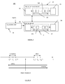
- Figure 3 represents a system 300 for dynamically optimizing a digital sensor 3, according to certain embodiments.
- the digital sensor 3 is configured to protect a digital circuit or sub-circuit 30 (also referred to as a "protection target” or “protected target”) fed by a clock signal having a clock period by triggering an alarm depending on a triggering condition related to the clock period and to an optimal alarm threshold.
- the system 300 comprises a calibration device 31 configured to determine the optimal alarm threshold by minimizing a quantity depending on the probability of occurrence of false positives and the probability of occurrence of false negatives.
- Varying operating conditions may comprise for example variation of the clock frequency due to smart power management. It is another advantage of the invention to lower the probability of false alarm when no critical operation is being performed, and to allow for a dynamic selection of a more security-wise stringent configuration otherwise.
- the various embodiments of the invention may allow for optimizing the operation of the digital sensor whatever its sensitivity.
- Such sensitivity of a digital sensor may depend on its architectural parameters, and in particular on the propagation delay of standard cells in the digital sensor data path and/or on the number of cells in the digital sensor data path.
- the digital sensor 3 may be used for example for detection of potentially malevolent attacks on the protection target 30.
- the target digital circuit 30 is schematically represented in Figure 3 .
- the target digital circuit 30 may comprise an input memory element 33 for storing input data, a data path 34 for propagating the input data and an output memory element 35 for storing the data propagated through the data path 34.
- the data path may comprise a number of combinatorial standard cells 340 responsible for computing the value to be stored in the output memory element 35. It should be noted that even if the digital sensor 3 and the target digital circuit 30 are represented as separate functional blocks in figure 3 , in practice they may be implemented on a same circuit.
- the digital sensor 3 thus provided satisfies a safety condition and a security condition.
- the safety condition no false alarm should be raised by the digital sensor 3. Indeed, for some security-critical systems such an alarm may trigger the erasure of all valuable data in the protection target, thus stopping the protection target from functioning any longer.
- the safety condition defines that no alarm should be raised by the digital sensor unless the protection target is in out-of-specifications operating conditions.
- the security condition no false negative should arise.
- the digital sensor 3 in response to the successful creation of a faulty computation into the targeted digital circuit by an attacker, the digital sensor 3 can also be affected and raise an alarm to prevent the digital sensor from missing security events.
- the calibration device 31 further allows for an optimization of the parameters of the digital sensor 3 so as to satisfy the safety condition and/or the security condition.
- the digital sensor's parameters may include for example the number of standard cells 370 in the digital sensor data path 37.
- the optimization of the number of standard cells 370 is such that the digital sensor data path propagation delay is optimized with respect to the safety and security conditions, applied on the protection target (digital circuit to be protected).
- the propagation delay in the critical path of the digital sensor 3 may be set to be greater than the propagation delay of the critical path 34 of the protection target 30, which allows satisfying the security condition. Accordingly, if a setup time violation arises in the protection target's critical path because the clock period is shortened, it will also occur in the digital sensor's data path.
- the data path propagation delay of the digital sensor 3 may be set to be smaller than the smallest acceptable clock period predefined by the protection target 300 (for example by the by the protection target's specifications), which allows satisfying the safety condition.
- the digital sensor data path propagation delay is smaller than the smallest acceptable clock period as predefined by the protection target, no setup violation will arise in the digital sensor while operating under "normal" operating conditions, or equivalently no false alarm will arise.
- safety and security properties thus expressed consider setup time violations.
- safety and security properties may also be expressed for other type of violations, for example hold time violations.
- the security property would imply that an alarm is raised when the propagation delay in the digital sensor data path is smaller than a given threshold defined with respect to the protection target's shortest data path propagation delay.
- a hold time violation arises in the protection target data path, it may also arise in the digital sensor which generates an alarm.
- the safety property for hold time violations would imply that no alarm should be raised when the propagation delay in the protection target is above a specified threshold corresponding to normal operating conditions.
- Figure 4 illustrates the Safety and security properties applied to a protection target 30.
- the calibration device 31 may optimize the parameters of the digital sensor 3 by determining an optimal alarm threshold, thereby optimizing the security and safety conditions which may depend on several parameters, such as environmental variations (temperature, input voltage, input clock frequency), noise due to process variations (correlated, uncorrelated) or clock jitter as illustrated in figure 4 .
- environmental variations temperature, input voltage, input clock frequency
- noise due to process variations correlated, uncorrelated
- clock jitter clock jitter
- a conventional approach may consist in arbitrarily defining the alarm threshold and using great margins between the protection target critical path propagation delay and the alarm threshold and between the alarm threshold and clock period, which provides low circuit performances.
- the calibration device 31 optimizes the alarm threshold in smaller margins which provides more confidence in the design and greater performances while retaining optimum security and safety.
- the generation of the optimal alarm may take into account input data related to the protection target 30, silicon-related data (for example process variations, etc.) and a physical model of the minimization problem.
- the optimal alarm threshold can be determined by minimizing the quantity depending on the probability of occurrence of false positives and the probability of occurrence of false negatives. This quantity may further depend on other constraints related to power consumption, sensor gate count and surface, and/or resistance against aging effects. This can be achieved for example through the careful selection of the gates used for building the digital sensor data path.
- the digital sensor calibration unit 31 may minimize the quantity related to the probability of occurrence of false positives and the probability of occurrence of false negatives based on input parameters depending on:
- the probability of false negatives may be determined from the probability density of the critical path propagation delay of the target digital circuit 30 and the probability density of the alarm threshold. Further, the probability of false positives may be determined from the probability density of the alarm threshold 30 and the probability density of said clock period of the target digital circuit.
- the critical path propagation delay of the protection target 30, the data path propagation delay of the digital sensor 3 and/or the alarm threshold may behave as random variables with respective probability density functions p T c and p T alarm . More specifically, every physical instance of a protection target 30 may behave according to p T c for its critical path propagation delay, and every physical instance of a given digital sensor architecture with fixed parameters may behave according to p T alarm for its alarm threshold. This phenomenon is due to noise sampling during the manufacturing process. In other words, parameters T c and T alarm may be determined once during the manufacturing process.
- the clock period may behave as a random variable according to a probability density function p T clk .
- the clock period may not only sample manufacturing noise but also dynamic noise. Therefore, in certain embodiments, T clk may be determined at every clock cycle.
- Every probability density function p T c , p T alarm and p T clk may be characterized by its distribution, its mean value ⁇ T c , ⁇ T alarm , ⁇ T clk respectively and by its standard deviation ⁇ T c , ⁇ T alarm and ⁇ T clk respectively.
- probability density functions p T c , p T alarm and p T clk form the physical model.
- the parameters characterizing the physical model such as the type of distributions, standard deviations ( ⁇ T c , ⁇ T alarm and ⁇ T clk ) and mean values ( ⁇ T c , ⁇ T alarm , ⁇ T clk ) may be determined by the manufacturing node and process, by standard cells library, by operating conditions and/or protection target timing characteristics.
- the term "characterized model” will be used to refer to a model corresponding to a given set of manufacturing node, process, standard cells library, operating conditions and/or protection target timing characteristics.
- the safety and security conditions may be expressed through the probability of false alarm and probability of false negative according to equations E1 and E2 respectively:
- P FA ⁇ - ⁇ + ⁇ ⁇ p T alarm t alarm ⁇ ⁇ - ⁇ t alarm ⁇ p T clk t clk ⁇ dt clk ⁇ dt alarm
- P FN ⁇ - ⁇ + ⁇ ⁇ p T alarm t alarm ⁇ ⁇ t alarm + ⁇ ⁇ p T c t c ⁇ dt c ⁇ dt alarm
- the optimal alarm threshold is determined from the sum of the probability of occurrence of false positives weighted by a first weight ⁇ and the probability of occurrence of false negatives weighted by a second weight ⁇ .
- the first weight and the second weight represent the relative weights ⁇ and ⁇ of the safety and security conditions.
- the first and second weights are positive values.
- the optimal alarm threshold is thus determined by minimizing the quantity + .
- the calibration device 31 may further compute the discrete number n of elementary gates, based on the theoretical mean propagation delay of each elementary logic gate in the digital sensor data path ⁇ d and on the optimal alarm threshold, when the sensor critical path of the digital sensor 3 comprises a set of elementary gates of a same type.
- the optimization problem E3 can be rewritten according to the successive equations of exhibit A.
- This problem is usually convex for ⁇ alarm ⁇ [ ⁇ T c ; ⁇ T clk ] and can be solved either formally if the characterized physical model allows simplification of the equation, or numerically by means of a gradient descent for instance.
- finding the optimum configuration may amount to finding the value for which the derivative of the minimization problem's cost function equals 0, and studying the sign of the derivative.
- Equation E3.7 of Exhibit A the optimization problem amounts to finding the roots of a second order polynomial ax 2 + bx + c, and studying the sign of the polynomial to identifiy the root corresponding to the minimum of the cost function.
- a characterized model may be derived.
- the optimal alarm threshold position is in the middle of the time interval defined by [ ⁇ T c ; ⁇ T clk ].
- the digital sensor alarm threshold ⁇ alarm can be determined statically during the design phase. Alternatively, it can be selected dynamically by software at runtime, for example in order to select the optimal configuration among a predetermined set of possible configurations, each possible configuration being associated with a predetermined characterized model.
- the digital sensor alarm threshold can be also determined dynamically by hardware at runtime, for example in order to select the optimal sensor configuration among a predetermined set of possible configurations, according to the current operating conditions and/or current protection target 30.
- such a dynamic calibration function could take as an input the list of enabled protection target modules and the current operating conditions, for example the clock period and temperature, and select the most appropriate predetermined configuration.
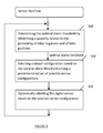
- FIGURE 5 is a flowchart depicting the method for dynamically calibrating the digital sensor according to certain embodiments, at runtime.
- the optimal alarm threshold is determined by minimizing a quantity related to the probability of false negatives and to the probability of false positives, for example by minimizing the sum of the probability of false negatives weighted by the first weight and probability of false positives weighted by the second weight.
- a sensor configuration is selected among a predetermined set of possible sensor configurations based on the optimal alarm threshold.
- the digital sensor is dynamically adjusted based on the selected configuration.
- the invention is not limited to a particular architecture of the digital circuit and/or of the digital sensor, and more specifically to a particular types of elementary gates in the sensor data path. Further, the invention may be also used for calibrating a hold time violation sensor, by studying the margins between the clock period, the alarm threshold and the protection target's shortest path propagation delay.
- Embodiments of the present invention can take the form of an embodiment containing both hardware and software elements.
- the calibration methods described herein can be implemented by computer program instructions supplied to the processor of any type of computer to produce a machine with a processor that executes the instructions to implement the functions/acts specified herein.
- These computer program instructions may also be stored in a computer-readable medium that can direct a computer to function in a particular manner. To that end, the computer program instructions may be loaded onto a computer to cause the performance of a series of operational steps and thereby produce a computer implemented process such that the executed instructions provide processes for implementing the functions/acts specified herein.
- ⁇ ⁇ alarm arg min ⁇ alarm ⁇ - ⁇ + ⁇ p T alarm t alarm ⁇ alarm ⁇ ⁇ ⁇ - ⁇ t alarm p T clk t clk ⁇ dt clk + ⁇ ⁇ t alarm + ⁇ p T c t c ⁇ d ⁇ t c ⁇ dt alarm
Abstract
Description
- The invention generally relates to digital circuits, and in particular to methods, systems, and computer program products for calibrating a digital sensor configured to protect a target digital circuit by triggering an alarm.
- The correctness of computations in a digital circuit depends on several physical and environmental parameters generally referred to as "operating conditions". Improper operating conditions may lead to a digital circuit outputting partially or totally bogus results and/or internal states. Since this phenomenon is produced by out-of-specifications operating conditions, they are often out of the designer's scope and may yield unexpected behavior.
- Attackers willing to gain control of sensitive assets from a targeted digital circuit such as a smartcard, a microprocessor, an ASIC (acronym for Application-Specific Integrated Circuit) or a FPGA (acronym for Field Programmable Gate Array) may use crafted out-of-specifications operating conditions to trigger a more or less loosely controlled unexpected behavior. This behavior may be characterized by the disclosure of sensitive assets such as cryptographic keys, the failure of one or more sensitive functions such as updating a sensitive value in a non-volatile memory, or the failure of an access control policy which results for example in granting access without correct credentials.
- Protecting embedded systems against such attacks has thus become paramount for many applications requiring protection of sensitive assets.
- As shown in
figure 1 , adigital circuit 1 mainly compriseprevious memory elements 10 andnext memory elements 12 interconnected by combinatorialstandard cells 11. Thememory elements standard cells 11 are responsible for computing the value to be stored in thenext memory elements 12, taking as input values the signals stored in theprevious memory elements 10. Combinatorial standard cells include memory less logic gates that may implement Boolean functions such as invertors, or, and, xor. Other combinatorial standard cells may include buffers whose function is to amplify and/or delay some data path. - The
memory elements - In order for the
memory elements - The logic
standard cells 12 between the memory elements form a set of data path. Every data path displays a propagation delay corresponding to the time required for a change of an input signal to be propagated through thestandard cells 12 to the output of the data path. The data path displaying the greatest propagation delay represents the critical path. - Violation of the setup time is a common source of faulty computations in digital circuits and one of the common techniques exploited by attackers for performing fault injection. Setup time violation may arise because the propagation delay in the data path is too long for the modifications to be propagated and stable early enough before the clock rising edge.
- In order to address this threat, a digital sensor architecture for protecting a digital circuit has been proposed by N. Selmane, S. Bhasin, S. Guilley, T. Graba and J.-L. Danger in "WDDL is Protected Against Setup Time Violation Attacks", FDTC 2009 and still improved in the article "Security evaluation of application-specific integrated circuits and field programmable gate arrays against setup time violation attacks" by N. Selmane, S. Bhasin, S. Guilley and J.-L. Danger in IET Information Security 2010.
Figure 2 illustrates suchdigital sensor 2. Thedigital sensor 2 comprises a digital circuit having aninput memory element 20 for storing a reference data, adata path 22 for propagating the reference data and anoutput memory element 23 for storing the data propagated through thedata path 22. The computation is deemed successful if the reference data correctly arrives from theinput memory element 20 to the output memory element in time for being sampled, that is to say within less than a clock cycle. Such a digital circuit may be further used to detect abnormal operating conditions. Such a circuit is built with the same logic elements than any other digital circuits. It is therefore also sensitive to out-of-specifications operating conditions. For example, if the temperature increases above a given threshold, the propagation delays of the combinatorial gates in the digitalsensor data path 22 will increase to the point where the data reaches theoutput memory element 23 after the clock rising edge. This late arrival may induce a faulty state in theoutput memory element 23 with respect to the reference signal. This faulty state can be detected by comparison of the values in thememory element - To protect the target digital circuit, the digital sensors triggers the alarm based on an alarm threshold selected arbitrarily in broad intervals. Accordingly, the target digital circuit operates with a much lower clock frequency than what it is really capable of handling, which results in low circuit performances.
- In order to address these and other problems, there is provided a calibration device as defined in the appended
independent claim 1, and a method of calibrating a device as defined in appended claim 14 and a computer program as defined in appended claim 15. Preferred embodiments are defined in the dependent claims. - By optimizing the alarm threshold so as to confine it in smaller margins between the protection target critical path propagation delay and the alarm threshold and between the alarm threshold and clock period, greater performance is achieved and optimum security and safety is retained.
- The accompanying drawings, which are incorporated in and constitute a part of this specification, illustrate various embodiments of the invention and, together with the general description of the invention given above, and the detailed description of the embodiments given below, serve to explain the embodiments of the invention.
-
Figure 1 is a schematic view of an exemplary digital circuit. -
Figure 2 is a schematic view of an exemplary digital sensor architecture. -
Figure 3 is a diagrammatic view of a system for calibrating a digital sensor. -
Figure 4 is a schematic view representing the safety and security properties applied to a protection target. -
Figure 5 is a flowchart depicting a process that may be executed to calibrate a digital sensor. -
Figure 6 is a diagram depicting the cost function as a function of the alarm threshold, according to an exemplary embodiment. -
Figure 7 is a diagram depicting the cost function as a function of the alarm threshold, according to another exemplary embodiment. - It is noted that the drawings of the invention are not necessarily to scale. The drawings are merely schematic representations. The drawings are intended to depict only typical embodiments of the invention, and therefore should not be considered as limiting the scope of the invention.
- Additionally, the detailed description is supplemented with Exhibit A. This Exhibit is placed apart for the purpose of clarifying the detailed description, and of enabling easier reference. They nevertheless form an integral part of the description of the present invention. This applies to the drawings as well.
-
Figure 3 represents asystem 300 for dynamically optimizing adigital sensor 3, according to certain embodiments. Thedigital sensor 3 is configured to protect a digital circuit or sub-circuit 30 (also referred to as a "protection target" or "protected target") fed by a clock signal having a clock period by triggering an alarm depending on a triggering condition related to the clock period and to an optimal alarm threshold. Thesystem 300 comprises acalibration device 31 configured to determine the optimal alarm threshold by minimizing a quantity depending on the probability of occurrence of false positives and the probability of occurrence of false negatives. - This allows for dynamically optimizing the
digital sensor 3 to adjust to varying operating conditions. Varying operating conditions may comprise for example variation of the clock frequency due to smart power management. It is another advantage of the invention to lower the probability of false alarm when no critical operation is being performed, and to allow for a dynamic selection of a more security-wise stringent configuration otherwise. - The various embodiments of the invention may allow for optimizing the operation of the digital sensor whatever its sensitivity. Such sensitivity of a digital sensor may depend on its architectural parameters, and in particular on the propagation delay of standard cells in the digital sensor data path and/or on the number of cells in the digital sensor data path.
- The
digital sensor 3 may be used for example for detection of potentially malevolent attacks on theprotection target 30. The targetdigital circuit 30 is schematically represented inFigure 3 . The targetdigital circuit 30 may comprise aninput memory element 33 for storing input data, adata path 34 for propagating the input data and anoutput memory element 35 for storing the data propagated through thedata path 34. The data path may comprise a number of combinatorialstandard cells 340 responsible for computing the value to be stored in theoutput memory element 35. It should be noted that even if thedigital sensor 3 and the targetdigital circuit 30 are represented as separate functional blocks infigure 3 , in practice they may be implemented on a same circuit. - The
digital sensor 3 thus provided satisfies a safety condition and a security condition. According to the safety condition, no false alarm should be raised by thedigital sensor 3. Indeed, for some security-critical systems such an alarm may trigger the erasure of all valuable data in the protection target, thus stopping the protection target from functioning any longer. In other words, the safety condition defines that no alarm should be raised by the digital sensor unless the protection target is in out-of-specifications operating conditions. According to the security condition, no false negative should arise. In other words, in response to the successful creation of a faulty computation into the targeted digital circuit by an attacker, thedigital sensor 3 can also be affected and raise an alarm to prevent the digital sensor from missing security events. - The
calibration device 31 further allows for an optimization of the parameters of thedigital sensor 3 so as to satisfy the safety condition and/or the security condition. The digital sensor's parameters may include for example the number ofstandard cells 370 in the digitalsensor data path 37. The optimization of the number ofstandard cells 370 is such that the digital sensor data path propagation delay is optimized with respect to the safety and security conditions, applied on the protection target (digital circuit to be protected). - In some embodiments, the propagation delay in the critical path of the
digital sensor 3 may be set to be greater than the propagation delay of thecritical path 34 of theprotection target 30, which allows satisfying the security condition. Accordingly, if a setup time violation arises in the protection target's critical path because the clock period is shortened, it will also occur in the digital sensor's data path. - Further, the data path propagation delay of the
digital sensor 3 may be set to be smaller than the smallest acceptable clock period predefined by the protection target 300 (for example by the by the protection target's specifications), which allows satisfying the safety condition. As a result, if the digital sensor data path propagation delay is smaller than the smallest acceptable clock period as predefined by the protection target, no setup violation will arise in the digital sensor while operating under "normal" operating conditions, or equivalently no false alarm will arise. - The safety and security properties thus expressed consider setup time violations. However, safety and security properties may also be expressed for other type of violations, for example hold time violations. In the example of hold time violations, the security property would imply that an alarm is raised when the propagation delay in the digital sensor data path is smaller than a given threshold defined with respect to the protection target's shortest data path propagation delay. As a result, if a hold time violation arises in the protection target data path, it may also arise in the digital sensor which generates an alarm. Similarly, the safety property for hold time violations would imply that no alarm should be raised when the propagation delay in the protection target is above a specified threshold corresponding to normal operating conditions.
- In the following detailed description, reference will be made to safety and security properties related to setup time violations for illustrative purpose only.
- To facilitate the description of the various embodiments of the invention, the following notations are defined below:
- Tc designates critical path propagation delay of the
protection target circuit 30; - Tclk designates acceptable clock period of the protection target circuit 30 (predefined for example by the protection target's specifications);
- Tc w.c. designates critical path propagation delay of the
protection target circuit 30, according to worst case condition (i.e. highest value); - Tclk w.c. designates the minimum acceptable clock period of the protection target circuit 30 (predefined for example by the protection target's specifications);
- Tc b.c. designates critical path propagation delay of the
protection target circuit 30, according to best case condition (i.e. lowest value); - Tclk b.c. designates the maximum acceptable clock period of the protection target circuit 30 (predefined for example by the protection target's specifications); The critical path propagation delay of the
digital sensor 3 will be referred to thereinafter as the "alarm threshold". -
Figure 4 illustrates the Safety and security properties applied to aprotection target 30. - The
calibration device 31 may optimize the parameters of thedigital sensor 3 by determining an optimal alarm threshold, thereby optimizing the security and safety conditions which may depend on several parameters, such as environmental variations (temperature, input voltage, input clock frequency), noise due to process variations (correlated, uncorrelated) or clock jitter as illustrated infigure 4 . By optimally positioning the alarm threshold, the failures due to false alarm as well as false negative are highly limited. - A conventional approach may consist in arbitrarily defining the alarm threshold and using great margins between the protection target critical path propagation delay and the alarm threshold and between the alarm threshold and clock period, which provides low circuit performances. The
calibration device 31 optimizes the alarm threshold in smaller margins which provides more confidence in the design and greater performances while retaining optimum security and safety. - To determine the optimal alarm threshold by minimizing the quantity depending on the probability of occurrence of false positives and the probability of occurrence of false negatives, the generation of the optimal alarm may take into account input data related to the
protection target 30, silicon-related data (for example process variations, etc.) and a physical model of the minimization problem. - Additionally, the optimal alarm threshold can be determined by minimizing the quantity depending on the probability of occurrence of false positives and the probability of occurrence of false negatives. This quantity may further depend on other constraints related to power consumption, sensor gate count and surface, and/or resistance against aging effects. This can be achieved for example through the careful selection of the gates used for building the digital sensor data path.
- More specifically, the digital
sensor calibration unit 31 may minimize the quantity related to the probability of occurrence of false positives and the probability of occurrence of false negatives based on input parameters depending on: - one or more acceptable operating conditions predefined by the
protection target 30, and/or - one or more protection target timing characteristics such as the critical path propagation delays according to the acceptable operating conditions, and/or
- at least one physical model, and/or
- one or more weights quantifying the relative importance between the safety and security conditions.
- In certain embodiments, the probability of false negatives may be determined from the probability density of the critical path propagation delay of the target
digital circuit 30 and the probability density of the alarm threshold. Further, the probability of false positives may be determined from the probability density of thealarm threshold 30 and the probability density of said clock period of the target digital circuit. - Indeed, according to a given set of operating conditions (also referred to as the "corner"), the critical path propagation delay of the
protection target 30, the data path propagation delay of thedigital sensor 3 and/or the alarm threshold may behave as random variables with respective probability density functions pTc and pTalarm . More specifically, every physical instance of aprotection target 30 may behave according to pTc for its critical path propagation delay, and every physical instance of a given digital sensor architecture with fixed parameters may behave according to pTalarm for its alarm threshold. This phenomenon is due to noise sampling during the manufacturing process. In other words, parameters Tc and Talarm may be determined once during the manufacturing process. - Similarly, the clock period may behave as a random variable according to a probability density function pT
clk . The clock period may not only sample manufacturing noise but also dynamic noise. Therefore, in certain embodiments, Tclk may be determined at every clock cycle. - Every probability density function pT
c , pTalarm and pTclk may be characterized by its distribution, its mean value µTc , µTalarm , µTclk respectively and by its standard deviation σTc , σTalarm and σTclk respectively. - These probability density functions pT
c , pTalarm and pTclk form the physical model. The parameters characterizing the physical model, such as the type of distributions, standard deviations (σTc , σTalarm and σTclk ) and mean values (µTc , µTalarm , µTclk ) may be determined by the manufacturing node and process, by standard cells library, by operating conditions and/or protection target timing characteristics. In the following description, the term "characterized model" will be used to refer to a model corresponding to a given set of manufacturing node, process, standard cells library, operating conditions and/or protection target timing characteristics. - Given a characterized model, the safety and security conditions may be expressed through the probability of false alarmand probability of false negative
 according to equations E1 and E2 respectively:


- In certain embodiments, the optimal alarm threshold is determined from the sum of the probability of occurrence of false positivesweighted by a first weight α and the probability of occurrence of false negatives
 weighted by a second weight β. The first weight and the second weight represent the relative weights α and β of the safety and security conditions. In preferred embodiments, the first and second weights are positive values. In one exemplary embodiment, the first and second weights may be selected such that α = 1 - β.
- In one embodiment, the optimal alarm threshold
µ alarm may be determined according to E3:
- According to E3, the optimal alarm threshold is thus determined by minimizing the quantity+
 .
.
- The
calibration device 31 may further compute the discrete number n of elementary gates, based on the theoretical mean propagation delay of each elementary logic gate in the digital sensor data path µd and on the optimal alarm threshold, when the sensor critical path of thedigital sensor 3 comprises a set of elementary gates of a same type. In particular, the discrete number n of elementary gates may be determined according to the following equation:
- The optimization problem E3 can be rewritten according to the successive equations of exhibit A. This problem is usually convex for µalarm ∈ [µT
c ; µTclk ] and can be solved either formally if the characterized physical model allows simplification of the equation, or numerically by means of a gradient descent for instance. Under this hypothesis, finding the optimum configuration may amount to finding the value for which the derivative of the minimization problem's cost function equals 0, and studying the sign of the derivative. As shown by Equation E3.7 of Exhibit A, the optimization problem amounts to finding the roots of a second order polynomial ax2 + bx + c, and studying the sign of the polynomial to identifiy the root corresponding to the minimum of the cost function. - As a first example, according to equation E3.7, if a = 0, that is to say σT
clk = σTc = σalarm = σ, the optimization problem has only the following solution :
- According to another example if a ≠ 0, the sign of the discriminant Δ = b2 - 4ac may be used to determine the optimal alarm threshold. Specifically:
- If Δ < 0, the roots are complex and no solution can be found,
- If Δ ≥ 0, there exists at least one solution. Generally σT
clk < σTc and therefore
µ alarm being the smallest root of the polynomial, that is if Δ > 0 :
- And if a > 0


- Depending on the targeted manufacturing process, the technology node, the standard cells library and/or protection target's characteristics, a characterized model may be derived.
- In one example, a case where σT
clk = σTc = σalarm and α = β is considered. - In such exemplary case,
µ alarm is given by:

- In this first example, the optimal alarm threshold position is in the middle of the time interval defined by [µT
c ; µTclk ]. - In a second example, a model is used whereby both the protection target critical path propagation delay and the digital sensor alarm threshold follow a Gaussian distribution of same variance σ and mean values µT
c and µalarm respectively. It is assumed that the clock period has no jitter, that is to say its probability density function has a zero variance σTclk = 0, that is to say the clock period is deterministic Tclk = µTclk . In the second example, α and β are equal to
- The second example results in the following sequence of Equations :


- As an example, for µT
c = 2ns, µTclk = 4ns and σ = 80ps, equation E8.4 and E8.5 result respectively in :

- Accordingly, the optimal alarm is equal to
µ alarm = 3.17ns. - The digital sensor alarm threshold
µ alarm can be determined statically during the design phase. Alternatively, it can be selected dynamically by software at runtime, for example in order to select the optimal configuration among a predetermined set of possible configurations, each possible configuration being associated with a predetermined characterized model. The digital sensor alarm threshold can be also determined dynamically by hardware at runtime, for example in order to select the optimal sensor configuration among a predetermined set of possible configurations, according to the current operating conditions and/orcurrent protection target 30. - For example, such a dynamic calibration function could take as an input the list of enabled protection target modules and the current operating conditions, for example the clock period and temperature, and select the most appropriate predetermined configuration.
-
FIGURE 5 is a flowchart depicting the method for dynamically calibrating the digital sensor according to certain embodiments, at runtime. - In
block 500, the optimal alarm threshold is determined by minimizing a quantity related to the probability of false negatives and to the probability of false positives, for example by minimizing the sum of the probability of false negatives weighted by the first weight and probability of false positives weighted by the second weight. - In
block 502, a sensor configuration is selected among a predetermined set of possible sensor configurations based on the optimal alarm threshold. - In
block 504, the digital sensor is dynamically adjusted based on the selected configuration. -
Figure 6 shows a diagram representing the cost function between µTc and µTclk , according to an exemplary implementation of the invention with µTc = 2ns, µTclk = 4ns, σ = 80ps and α = β. This diagram graphically expresses the correctness of the results. - From the graph of the cost function represented in
figure 6 , it can be observed that, under such constraints, deviating from the optimal alarm threshold value results in a quickly increasing cost so that an arbitrary selection of the alarm threshold, like in conventional approaches, result in poor performance. -
Figure 7 shows a diagram representing the cost function between µTc and µTclk , according to another exemplary implementation of the invention with µ Tc = 2ns, µ Tclk = 8ns, σ = 80ps and α = β. From this graph of the cost function with µ Tclk = 8ns, it can be observed that the increased margins provide more room for deviation and error from the optimal alarm threshold. Indeed, deviating from an optimal value would not result in too dramatic an increase of the cost function. However, under such conditions the circuit functions is at a half the frequency as compared to the diagram of infigure 4 . - While embodiments of the invention have been illustrated by a description of various examples, and while these embodiments have been described in considerable detail, it is not the intention of the applicant to restrict or in any way limit the scope of the appended claims to such detail. In particular, the invention is not limited to a particular architecture of the digital circuit and/or of the digital sensor, and more specifically to a particular types of elementary gates in the sensor data path. Further, the invention may be also used for calibrating a hold time violation sensor, by studying the margins between the clock period, the alarm threshold and the protection target's shortest path propagation delay.
- Additional advantages and modifications will readily appear to those skilled in the art. The invention in its broader aspects is therefore not limited to the specific details, representative methods, and illustrative examples shown and described. Accordingly, departures may be made from such details without departing from the spirit or scope of applicant's general inventive concept.
- Embodiments of the present invention can take the form of an embodiment containing both hardware and software elements.
- Furthermore, the calibration methods described herein can be implemented by computer program instructions supplied to the processor of any type of computer to produce a machine with a processor that executes the instructions to implement the functions/acts specified herein. These computer program instructions may also be stored in a computer-readable medium that can direct a computer to function in a particular manner. To that end, the computer program instructions may be loaded onto a computer to cause the performance of a series of operational steps and thereby produce a computer implemented process such that the executed instructions provide processes for implementing the functions/acts specified herein.
- The optimization problem E3 can be rewritten as:

- By expanding the first integral and assuming that the probability density functions are Gaussian, this provides :


- By noting


- As

- Further, as


- As the problem is usually convex, for µalarm ∈ [µ T
c ; µ Tclk ], finding the optimum configuration may amount to finding the value for which the derivative of the minimization problem's cost function equals 0, and studying the sign of the derivative. Thus, the values of µ alarm that are to be found satisfy the following property E3.5:
- Which is equivalent to equation E3.6:

- By composing the both terms of E3.6 by the strictly increasing function x → log(x), this leads to E3.7 :

Claims (15)
- A calibration device for calibrating a digital sensor (3), said digital sensor being configured to protect a target digital circuit (30) fed by a clock signal having a clock period by triggering an alarm depending on a triggering condition related to said clock period and to an optimal alarm threshold, said optimal alarm threshold being determined by minimizing a quantity depending on the probability of occurrence of false positives and on the probability of occurrence of false negatives.
- The calibration device of claim 1, wherein the probability of false negatives is determined from the probability density of the critical path propagation delay of the target digital circuit (30) and the probability density of the alarm threshold.
- The calibration device of claim 2, wherein the probability of false negatives is determined according to the following equation:

where t alarm designates the alarm threshold, p Talarm designates the probability density of the alarm threshold, t c designates the critical path propagation delay of the target digital circuit (30), and p Tc designates the probability density of the critical path propagation delay of the target digital circuit (30). - The calibration device of any preceding claim, wherein the probability of false positives is determined from the probability density of the alarm threshold (30) and the probability density of said clock period of the target digital circuit.
- The calibration device of claim 4, wherein the probability of false positives is determined according to the following equation:

where t alarm designates the alarm threshold, p Talarm designates the probability density of the alarm threshold, p Tclk designates the probability density of the clock period and t clk designates the clock period. - The calibration device of any preceding claim, wherein said quantity depends on the sum of the probability of occurrence of false positivesweighted by a first weight and the probability of occurrence of false negatives
 weighted by a second weight.
- The calibration device of any preceding claim, wherein said optimal alarm threshold
µ alarm is determined according to the following equation:
in whichdesignates the probability of occurrence of false positives, α designates the first weight, designates the probability of occurrence of false negatives, and β designates the a second weight.
- The calibration device of any preceding claim, wherein said optimal alarm threshold is determined dynamically during the operation of the digital sensor based on a current operating condition and the critical path propagation delay of the target digital circuit.
- The calibration device of any preceding claim, wherein the digital sensor comprises a sensor critical path comprising a set of elementary gates, said elementary gates being of a unique type, and wherein the number of elementary gates is determined from said optimal alarm threshold and the digital sensor data path.
- The calibration device of claim 9, wherein said number of elementary gates n is determined from the optimal alarm threshold
µ lalarm according to the following equation:
in which µd designates the digital sensor data path elementary gate mean delay. - The calibration device of any preceding claim 2 to 5 wherein each probability density follows a Gaussian distribution.
- The calibration device of claim 11, wherein each probability density comprises a mean value and a variance, wherein if the probability density variances are all equal, and the optimal alarm threshold is determined between the mean value µT
c of the probability density of the critical path propagation delay of the target digital circuit (30) and the mean value µTclk of the probability density of the clock period of the target digital circuit. - The calibration device of any preceding claim, wherein said triggering condition is verified if said optimal alarm threshold exceeds the clock period.
- A calibration method for calibrating a digital sensor (3), said digital sensor being configured to protect a target digital circuit (30) fed by a clock signal having a clock period, by triggering an alarm depending on a condition between said clock signal and an optimal alarm threshold, said method comprising determining said optimal alarm threshold by minimizing a quantity depending on the probability of occurrence of false positives and the probability of occurrence of false negatives.
- A computer program product comprising:a non-transitory computer readable storage medium; andinstructions stored on the non-transitory computer readable storage medium that, when executed by a processor, cause the processor to calibrate a digital sensor (3), said digital sensor being configured to protect a target digital circuit (30) fed by a clock signal having a clock period, by triggering an alarm depending on a condition between said clock signal and an optimal alarm threshold, said calibration of the digital sensor comprising determining said optimal alarm threshold by minimizing a quantity depending on the probability of occurrence of false positives and the probability of occurrence of false negatives.
Priority Applications (5)
| Application Number | Priority Date | Filing Date | Title |
|---|---|---|---|
| EP14306036.6A EP2960665B1 (en) | 2014-06-27 | 2014-06-27 | Device and method for calibrating a digital sensor |
| PCT/EP2015/064599 WO2015197853A1 (en) | 2014-06-27 | 2015-06-26 | Device and method for calibrating a digital sensor |
| CN201580034529.8A CN106716072B (en) | 2014-06-27 | 2015-06-26 | Apparatus and method for calibrating a digital sensor |
| US15/321,511 US10571313B2 (en) | 2014-06-27 | 2015-06-26 | Device and method for calibrating a digital sensor |
| HK16106051.5A HK1218160A1 (en) | 2014-06-27 | 2016-05-27 | Device and method for calibrating a digital sensor |
Applications Claiming Priority (1)
| Application Number | Priority Date | Filing Date | Title |
|---|---|---|---|
| EP14306036.6A EP2960665B1 (en) | 2014-06-27 | 2014-06-27 | Device and method for calibrating a digital sensor |
Publications (2)
| Publication Number | Publication Date |
|---|---|
| EP2960665A1 true EP2960665A1 (en) | 2015-12-30 |
| EP2960665B1 EP2960665B1 (en) | 2017-05-24 |
Family
ID=51228385
Family Applications (1)
| Application Number | Title | Priority Date | Filing Date |
|---|---|---|---|
| EP14306036.6A Active EP2960665B1 (en) | 2014-06-27 | 2014-06-27 | Device and method for calibrating a digital sensor |
Country Status (5)
| Country | Link |
|---|---|
| US (1) | US10571313B2 (en) |
| EP (1) | EP2960665B1 (en) |
| CN (1) | CN106716072B (en) |
| HK (1) | HK1218160A1 (en) |
| WO (1) | WO2015197853A1 (en) |
Cited By (4)
| Publication number | Priority date | Publication date | Assignee | Title |
|---|---|---|---|---|
| CN109241793A (en) * | 2018-07-17 | 2019-01-18 | 深圳市德卡科技股份有限公司 | A kind of IC card and its data control method and device |
| EP3506548A1 (en) | 2017-12-27 | 2019-07-03 | Secure-IC SAS | Quantitative digital sensor |
| US10489595B2 (en) | 2016-11-15 | 2019-11-26 | Huawei Technologies Co., Ltd. | Method and detection circuit for detecting security chip operating state |
| CN110633450A (en) * | 2018-06-06 | 2019-12-31 | 中国石油化工股份有限公司 | Method for optimizing alarm threshold of hydrogen peroxide device alarm system |
Families Citing this family (2)
| Publication number | Priority date | Publication date | Assignee | Title |
|---|---|---|---|---|
| DE102018121349A1 (en) * | 2018-08-31 | 2020-03-05 | B. Braun Avitum Ag | Self-learning input filter for medical devices |
| DE102019130395A1 (en) * | 2019-11-11 | 2021-05-12 | Infineon Technologies Ag | Storage element with clock gating |
Citations (1)
| Publication number | Priority date | Publication date | Assignee | Title |
|---|---|---|---|---|
| US20130300463A1 (en) * | 2012-05-11 | 2013-11-14 | Stichting Imec Nederland | Method and Apparatus for Monitoring Timing of Critical Paths |
Family Cites Families (8)
| Publication number | Priority date | Publication date | Assignee | Title |
|---|---|---|---|---|
| US4266218A (en) * | 1978-10-12 | 1981-05-05 | Cherry Semiconductor Corporation | Alarm system control circuit |
| ATE536801T1 (en) * | 2004-01-15 | 2011-12-15 | Koninkl Philips Electronics Nv | ADAPTIVE PHYSIOLOGICAL MONITORING SYSTEM AND METHOD OF USE THEREOF |
| US7076385B2 (en) * | 2004-11-23 | 2006-07-11 | Guide Technology, Inc. | System and method for calibrating signal paths connecting a device under test to a test system |
| KR101322434B1 (en) * | 2005-07-11 | 2013-10-28 | 브룩스 오토메이션 인코퍼레이티드 | Intelligent condition-monitoring and fault diagnostic system |
| US9432271B2 (en) * | 2009-06-15 | 2016-08-30 | Qualcomm Incorporated | Sensor network management |
| CN102636216A (en) * | 2012-04-28 | 2012-08-15 | 无锡永阳电子科技有限公司 | Sensor signal calibration device |
| KR102449214B1 (en) * | 2015-05-13 | 2022-09-30 | 주식회사 에이치엘클레무브 | Method for estimating direction of arrival and apparatus for estimating direction of arrival using the same |
| US10164572B2 (en) * | 2016-08-18 | 2018-12-25 | M2Communication Inc. | Method of monitoring clock and oscillator module thereof |
-
2014
- 2014-06-27 EP EP14306036.6A patent/EP2960665B1/en active Active
-
2015
- 2015-06-26 CN CN201580034529.8A patent/CN106716072B/en active Active
- 2015-06-26 US US15/321,511 patent/US10571313B2/en active Active
- 2015-06-26 WO PCT/EP2015/064599 patent/WO2015197853A1/en active Application Filing
-
2016
- 2016-05-27 HK HK16106051.5A patent/HK1218160A1/en unknown
Patent Citations (1)
| Publication number | Priority date | Publication date | Assignee | Title |
|---|---|---|---|---|
| US20130300463A1 (en) * | 2012-05-11 | 2013-11-14 | Stichting Imec Nederland | Method and Apparatus for Monitoring Timing of Critical Paths |
Non-Patent Citations (5)
| Title |
|---|
| N. SELMANE; S. BHASIN; S. GUILLEY; J.-L. DANGER: "Security evaluation of application-specific integrated circuits and field programmable gate arrays against setup time violation attacks", IET INFORMATION SECURITY, 2010 |
| N. SELMANE; S. BHASIN; S. GUILLEY; T. GRABA; J.-L. DANGER: "WDDL is Protected Against Setup Time Violation Attacks", FDTC, 2009 |
| NIMAY SHAH ET AL: "Built-In Proactive Tuning System for Circuit Aging Resilience", DEFECT AND FAULT TOLERANCE OF VLSI SYSTEMS, 2008. DFTVS '08. IEEE INTERNATIONAL SYMPOSIUM ON, IEEE, PISCATAWAY, NJ, USA, 1 October 2008 (2008-10-01), pages 96 - 104, XP031345543, ISBN: 978-0-7695-3365-0 * |
| SHENG WEI ET AL: "Integrated circuit security techniques using variable supply voltage", DESIGN AUTOMATION CONFERENCE (DAC), 2011 48TH ACM/EDAC/IEEE, IEEE, 5 June 2011 (2011-06-05), pages 248 - 253, XP031927664, ISBN: 978-1-4503-0636-2 * |
| TOSHINORI SATO ET AL: "A Simple Flip-Flop Circuit for Typical-Case Designs for DFM", QUALITY ELECTRONIC DESIGN, 2007. ISQED '07. 8TH INTERNATIONAL SYM POSIUM ON, IEEE, PI, 1 March 2007 (2007-03-01), pages 539 - 544, XP031074093, ISBN: 978-0-7695-2795-6 * |
Cited By (6)
| Publication number | Priority date | Publication date | Assignee | Title |
|---|---|---|---|---|
| US10489595B2 (en) | 2016-11-15 | 2019-11-26 | Huawei Technologies Co., Ltd. | Method and detection circuit for detecting security chip operating state |
| EP3506548A1 (en) | 2017-12-27 | 2019-07-03 | Secure-IC SAS | Quantitative digital sensor |
| WO2019129439A1 (en) | 2017-12-27 | 2019-07-04 | Secure-Ic Sas | Quantitative digital sensor |
| US11893112B2 (en) | 2017-12-27 | 2024-02-06 | Secure-Ic Sas | Quantitative digital sensor |
| CN110633450A (en) * | 2018-06-06 | 2019-12-31 | 中国石油化工股份有限公司 | Method for optimizing alarm threshold of hydrogen peroxide device alarm system |
| CN109241793A (en) * | 2018-07-17 | 2019-01-18 | 深圳市德卡科技股份有限公司 | A kind of IC card and its data control method and device |
Also Published As
| Publication number | Publication date |
|---|---|
| HK1218160A1 (en) | 2017-02-03 |
| US10571313B2 (en) | 2020-02-25 |
| CN106716072A (en) | 2017-05-24 |
| CN106716072B (en) | 2020-06-23 |
| US20170160112A1 (en) | 2017-06-08 |
| EP2960665B1 (en) | 2017-05-24 |
| WO2015197853A1 (en) | 2015-12-30 |
Similar Documents
| Publication | Publication Date | Title |
|---|---|---|
| EP2960665B1 (en) | Device and method for calibrating a digital sensor | |
| US11893112B2 (en) | Quantitative digital sensor | |
| EP2294526B1 (en) | A method for secure data reading and a data handling system | |
| US10019571B2 (en) | Protection from side-channel attacks by varying clock delays | |
| US9712330B2 (en) | Physically uncloneable function device using MRAM | |
| US11171793B2 (en) | Method and system for detecting an attack on a physically unclonable function (PUF) | |
| US8990578B2 (en) | Password authentication circuit and method | |
| JP6968234B2 (en) | Electronic devices and methods for performing data sampling integrity checks using flip-flops with relative delay | |
| US10976360B2 (en) | Aging-sensitive recycling sensors for chip authentication | |
| Igarashi et al. | Concurrent faulty clock detection for crypto circuits against clock glitch based DFA | |
| CN106484945B (en) | Method for analyzing logic circuit | |
| US9367440B2 (en) | Memory device | |
| US10148671B2 (en) | Method for protecting a chip card against a physical attack intended to modify the logical behaviour of a functional program | |
| US9793895B2 (en) | Electronic circuit, latch circuit, and external action detecting circuit | |
| US20230367912A1 (en) | Semiconductor chip apparatus and method for checking the integrity of a memory | |
| EP4137975A1 (en) | Method and system for verification of redundant-check countermeasures | |
| Perumalla et al. | Memometer: Memory PUF-Based Hardware Metering Methodology for FPGAs | |
| US20230229759A1 (en) | Method for detecting a fault injection in a data processing system | |
| US20230244820A1 (en) | Integrated circuit protection against reverse engineering | |
| US20240126874A1 (en) | Security processing device, method and electronic device for handling attacks | |
| Restrepo-Calle et al. | On the definition of real conditions for a fault injection experiment on embedded systems |
Legal Events
| Date | Code | Title | Description |
|---|---|---|---|
| PUAI | Public reference made under article 153(3) epc to a published international application that has entered the european phase |
Free format text: ORIGINAL CODE: 0009012 |
|
| AK | Designated contracting states |
Kind code of ref document: A1 Designated state(s): AL AT BE BG CH CY CZ DE DK EE ES FI FR GB GR HR HU IE IS IT LI LT LU LV MC MK MT NL NO PL PT RO RS SE SI SK SM TR |
|
| AX | Request for extension of the european patent |
Extension state: BA ME |
|
| 17P | Request for examination filed |
Effective date: 20160629 |
|
| RBV | Designated contracting states (corrected) |
Designated state(s): AL AT BE BG CH CY CZ DE DK EE ES FI FR GB GR HR HU IE IS IT LI LT LU LV MC MK MT NL NO PL PT RO RS SE SI SK SM TR |
|
| GRAP | Despatch of communication of intention to grant a patent |
Free format text: ORIGINAL CODE: EPIDOSNIGR1 |
|
| INTG | Intention to grant announced |
Effective date: 20161123 |
|
| REG | Reference to a national code |
Ref country code: HK Ref legal event code: DE Ref document number: 1218160 Country of ref document: HK |
|
| GRAJ | Information related to disapproval of communication of intention to grant by the applicant or resumption of examination proceedings by the epo deleted |
Free format text: ORIGINAL CODE: EPIDOSDIGR1 |
|
| RAP1 | Party data changed (applicant data changed or rights of an application transferred) |
Owner name: SECURE-IC SAS |
|
| GRAS | Grant fee paid |
Free format text: ORIGINAL CODE: EPIDOSNIGR3 |
|
| GRAP | Despatch of communication of intention to grant a patent |
Free format text: ORIGINAL CODE: EPIDOSNIGR1 |
|
| INTC | Intention to grant announced (deleted) | ||
| GRAA | (expected) grant |
Free format text: ORIGINAL CODE: 0009210 |
|
| INTG | Intention to grant announced |
Effective date: 20170329 |
|
| AK | Designated contracting states |
Kind code of ref document: B1 Designated state(s): AL AT BE BG CH CY CZ DE DK EE ES FI FR GB GR HR HU IE IS IT LI LT LU LV MC MK MT NL NO PL PT RO RS SE SI SK SM TR |
|
| REG | Reference to a national code |
Ref country code: GB Ref legal event code: FG4D |
|
| REG | Reference to a national code |
Ref country code: FR Ref legal event code: PLFP Year of fee payment: 4 |
|
| REG | Reference to a national code |
Ref country code: CH Ref legal event code: EP |
|
| REG | Reference to a national code |
Ref country code: IE Ref legal event code: FG4D |
|
| REG | Reference to a national code |
Ref country code: AT Ref legal event code: REF Ref document number: 896279 Country of ref document: AT Kind code of ref document: T Effective date: 20170615 |
|
| REG | Reference to a national code |
Ref country code: DE Ref legal event code: R096 Ref document number: 602014010090 Country of ref document: DE |
|
| REG | Reference to a national code |
Ref country code: NL Ref legal event code: FP |
|
| REG | Reference to a national code |
Ref country code: LT Ref legal event code: MG4D |
|
| REG | Reference to a national code |
Ref country code: AT Ref legal event code: MK05 Ref document number: 896279 Country of ref document: AT Kind code of ref document: T Effective date: 20170524 |
|
| PG25 | Lapsed in a contracting state [announced via postgrant information from national office to epo] |
Ref country code: ES Free format text: LAPSE BECAUSE OF FAILURE TO SUBMIT A TRANSLATION OF THE DESCRIPTION OR TO PAY THE FEE WITHIN THE PRESCRIBED TIME-LIMIT Effective date: 20170524 Ref country code: HR Free format text: LAPSE BECAUSE OF FAILURE TO SUBMIT A TRANSLATION OF THE DESCRIPTION OR TO PAY THE FEE WITHIN THE PRESCRIBED TIME-LIMIT Effective date: 20170524 Ref country code: NO Free format text: LAPSE BECAUSE OF FAILURE TO SUBMIT A TRANSLATION OF THE DESCRIPTION OR TO PAY THE FEE WITHIN THE PRESCRIBED TIME-LIMIT Effective date: 20170824 Ref country code: LT Free format text: LAPSE BECAUSE OF FAILURE TO SUBMIT A TRANSLATION OF THE DESCRIPTION OR TO PAY THE FEE WITHIN THE PRESCRIBED TIME-LIMIT Effective date: 20170524 Ref country code: GR Free format text: LAPSE BECAUSE OF FAILURE TO SUBMIT A TRANSLATION OF THE DESCRIPTION OR TO PAY THE FEE WITHIN THE PRESCRIBED TIME-LIMIT Effective date: 20170825 Ref country code: AT Free format text: LAPSE BECAUSE OF FAILURE TO SUBMIT A TRANSLATION OF THE DESCRIPTION OR TO PAY THE FEE WITHIN THE PRESCRIBED TIME-LIMIT Effective date: 20170524 Ref country code: FI Free format text: LAPSE BECAUSE OF FAILURE TO SUBMIT A TRANSLATION OF THE DESCRIPTION OR TO PAY THE FEE WITHIN THE PRESCRIBED TIME-LIMIT Effective date: 20170524 |
|
| PG25 | Lapsed in a contracting state [announced via postgrant information from national office to epo] |
Ref country code: BG Free format text: LAPSE BECAUSE OF FAILURE TO SUBMIT A TRANSLATION OF THE DESCRIPTION OR TO PAY THE FEE WITHIN THE PRESCRIBED TIME-LIMIT Effective date: 20170824 Ref country code: LV Free format text: LAPSE BECAUSE OF FAILURE TO SUBMIT A TRANSLATION OF THE DESCRIPTION OR TO PAY THE FEE WITHIN THE PRESCRIBED TIME-LIMIT Effective date: 20170524 Ref country code: RS Free format text: LAPSE BECAUSE OF FAILURE TO SUBMIT A TRANSLATION OF THE DESCRIPTION OR TO PAY THE FEE WITHIN THE PRESCRIBED TIME-LIMIT Effective date: 20170524 Ref country code: IS Free format text: LAPSE BECAUSE OF FAILURE TO SUBMIT A TRANSLATION OF THE DESCRIPTION OR TO PAY THE FEE WITHIN THE PRESCRIBED TIME-LIMIT Effective date: 20170924 Ref country code: SE Free format text: LAPSE BECAUSE OF FAILURE TO SUBMIT A TRANSLATION OF THE DESCRIPTION OR TO PAY THE FEE WITHIN THE PRESCRIBED TIME-LIMIT Effective date: 20170524 |
|
| PG25 | Lapsed in a contracting state [announced via postgrant information from national office to epo] |
Ref country code: RO Free format text: LAPSE BECAUSE OF FAILURE TO SUBMIT A TRANSLATION OF THE DESCRIPTION OR TO PAY THE FEE WITHIN THE PRESCRIBED TIME-LIMIT Effective date: 20170524 Ref country code: CZ Free format text: LAPSE BECAUSE OF FAILURE TO SUBMIT A TRANSLATION OF THE DESCRIPTION OR TO PAY THE FEE WITHIN THE PRESCRIBED TIME-LIMIT Effective date: 20170524 Ref country code: DK Free format text: LAPSE BECAUSE OF FAILURE TO SUBMIT A TRANSLATION OF THE DESCRIPTION OR TO PAY THE FEE WITHIN THE PRESCRIBED TIME-LIMIT Effective date: 20170524 Ref country code: EE Free format text: LAPSE BECAUSE OF FAILURE TO SUBMIT A TRANSLATION OF THE DESCRIPTION OR TO PAY THE FEE WITHIN THE PRESCRIBED TIME-LIMIT Effective date: 20170524 Ref country code: SK Free format text: LAPSE BECAUSE OF FAILURE TO SUBMIT A TRANSLATION OF THE DESCRIPTION OR TO PAY THE FEE WITHIN THE PRESCRIBED TIME-LIMIT Effective date: 20170524 |
|
| REG | Reference to a national code |
Ref country code: CH Ref legal event code: PL |
|
| REG | Reference to a national code |
Ref country code: DE Ref legal event code: R097 Ref document number: 602014010090 Country of ref document: DE |
|
| PG25 | Lapsed in a contracting state [announced via postgrant information from national office to epo] |
Ref country code: SM Free format text: LAPSE BECAUSE OF FAILURE TO SUBMIT A TRANSLATION OF THE DESCRIPTION OR TO PAY THE FEE WITHIN THE PRESCRIBED TIME-LIMIT Effective date: 20170524 Ref country code: IT Free format text: LAPSE BECAUSE OF FAILURE TO SUBMIT A TRANSLATION OF THE DESCRIPTION OR TO PAY THE FEE WITHIN THE PRESCRIBED TIME-LIMIT Effective date: 20170524 Ref country code: PL Free format text: LAPSE BECAUSE OF FAILURE TO SUBMIT A TRANSLATION OF THE DESCRIPTION OR TO PAY THE FEE WITHIN THE PRESCRIBED TIME-LIMIT Effective date: 20170524 |
|
| PLBE | No opposition filed within time limit |
Free format text: ORIGINAL CODE: 0009261 |
|
| STAA | Information on the status of an ep patent application or granted ep patent |
Free format text: STATUS: NO OPPOSITION FILED WITHIN TIME LIMIT |
|
| REG | Reference to a national code |
Ref country code: IE Ref legal event code: MM4A |
|
| PG25 | Lapsed in a contracting state [announced via postgrant information from national office to epo] |
Ref country code: IE Free format text: LAPSE BECAUSE OF NON-PAYMENT OF DUE FEES Effective date: 20170627 Ref country code: LU Free format text: LAPSE BECAUSE OF NON-PAYMENT OF DUE FEES Effective date: 20170627 Ref country code: LI Free format text: LAPSE BECAUSE OF NON-PAYMENT OF DUE FEES Effective date: 20170630 Ref country code: CH Free format text: LAPSE BECAUSE OF NON-PAYMENT OF DUE FEES Effective date: 20170630 |
|
| 26N | No opposition filed |
Effective date: 20180227 |
|
| REG | Reference to a national code |
Ref country code: FR Ref legal event code: PLFP Year of fee payment: 5 |
|
| PG25 | Lapsed in a contracting state [announced via postgrant information from national office to epo] |
Ref country code: SI Free format text: LAPSE BECAUSE OF FAILURE TO SUBMIT A TRANSLATION OF THE DESCRIPTION OR TO PAY THE FEE WITHIN THE PRESCRIBED TIME-LIMIT Effective date: 20170524 |
|
| REG | Reference to a national code |
Ref country code: BE Ref legal event code: MM Effective date: 20170630 |
|
| PG25 | Lapsed in a contracting state [announced via postgrant information from national office to epo] |
Ref country code: BE Free format text: LAPSE BECAUSE OF NON-PAYMENT OF DUE FEES Effective date: 20170630 |
|
| PG25 | Lapsed in a contracting state [announced via postgrant information from national office to epo] |
Ref country code: MT Free format text: LAPSE BECAUSE OF NON-PAYMENT OF DUE FEES Effective date: 20170627 |
|
| PG25 | Lapsed in a contracting state [announced via postgrant information from national office to epo] |
Ref country code: HU Free format text: LAPSE BECAUSE OF FAILURE TO SUBMIT A TRANSLATION OF THE DESCRIPTION OR TO PAY THE FEE WITHIN THE PRESCRIBED TIME-LIMIT; INVALID AB INITIO Effective date: 20140627 Ref country code: MC Free format text: LAPSE BECAUSE OF FAILURE TO SUBMIT A TRANSLATION OF THE DESCRIPTION OR TO PAY THE FEE WITHIN THE PRESCRIBED TIME-LIMIT Effective date: 20170524 |
|
| PG25 | Lapsed in a contracting state [announced via postgrant information from national office to epo] |
Ref country code: CY Free format text: LAPSE BECAUSE OF FAILURE TO SUBMIT A TRANSLATION OF THE DESCRIPTION OR TO PAY THE FEE WITHIN THE PRESCRIBED TIME-LIMIT Effective date: 20170524 |
|
| PG25 | Lapsed in a contracting state [announced via postgrant information from national office to epo] |
Ref country code: MK Free format text: LAPSE BECAUSE OF FAILURE TO SUBMIT A TRANSLATION OF THE DESCRIPTION OR TO PAY THE FEE WITHIN THE PRESCRIBED TIME-LIMIT Effective date: 20170524 |
|
| PG25 | Lapsed in a contracting state [announced via postgrant information from national office to epo] |
Ref country code: TR Free format text: LAPSE BECAUSE OF FAILURE TO SUBMIT A TRANSLATION OF THE DESCRIPTION OR TO PAY THE FEE WITHIN THE PRESCRIBED TIME-LIMIT Effective date: 20170524 |
|
| PG25 | Lapsed in a contracting state [announced via postgrant information from national office to epo] |
Ref country code: PT Free format text: LAPSE BECAUSE OF FAILURE TO SUBMIT A TRANSLATION OF THE DESCRIPTION OR TO PAY THE FEE WITHIN THE PRESCRIBED TIME-LIMIT Effective date: 20170524 |
|
| PG25 | Lapsed in a contracting state [announced via postgrant information from national office to epo] |
Ref country code: AL Free format text: LAPSE BECAUSE OF FAILURE TO SUBMIT A TRANSLATION OF THE DESCRIPTION OR TO PAY THE FEE WITHIN THE PRESCRIBED TIME-LIMIT Effective date: 20170524 |
|
| PGFP | Annual fee paid to national office [announced via postgrant information from national office to epo] |
Ref country code: NL Payment date: 20230614 Year of fee payment: 10 Ref country code: FR Payment date: 20230608 Year of fee payment: 10 Ref country code: DE Payment date: 20230531 Year of fee payment: 10 |
|
| PGFP | Annual fee paid to national office [announced via postgrant information from national office to epo] |
Ref country code: GB Payment date: 20230525 Year of fee payment: 10 |