EP2960643A1 - System for monitoring a light transparent cover of a light or lamp, especially of an aircraft's external light - Google Patents
System for monitoring a light transparent cover of a light or lamp, especially of an aircraft's external light Download PDFInfo
- Publication number
- EP2960643A1 EP2960643A1 EP14425086.7A EP14425086A EP2960643A1 EP 2960643 A1 EP2960643 A1 EP 2960643A1 EP 14425086 A EP14425086 A EP 14425086A EP 2960643 A1 EP2960643 A1 EP 2960643A1
- Authority
- EP
- European Patent Office
- Prior art keywords
- light
- cover
- field
- monitoring system
- permeable cover
- Prior art date
- Legal status (The legal status is an assumption and is not a legal conclusion. Google has not performed a legal analysis and makes no representation as to the accuracy of the status listed.)
- Granted
Links
- 238000012544 monitoring process Methods 0.000 title claims abstract description 78
- 238000001514 detection method Methods 0.000 claims abstract description 38
- 230000002093 peripheral effect Effects 0.000 claims abstract description 26
- 230000000644 propagated effect Effects 0.000 claims abstract description 6
- 230000035699 permeability Effects 0.000 claims description 20
- 238000012423 maintenance Methods 0.000 claims description 15
- 238000004891 communication Methods 0.000 claims description 11
- 230000005672 electromagnetic field Effects 0.000 claims description 4
- 238000012360 testing method Methods 0.000 description 12
- 238000000034 method Methods 0.000 description 8
- 238000005516 engineering process Methods 0.000 description 7
- 230000009467 reduction Effects 0.000 description 7
- 230000002459 sustained effect Effects 0.000 description 6
- 238000012986 modification Methods 0.000 description 5
- 230000004048 modification Effects 0.000 description 5
- 238000005259 measurement Methods 0.000 description 3
- 230000008901 benefit Effects 0.000 description 2
- 230000006866 deterioration Effects 0.000 description 2
- 230000005670 electromagnetic radiation Effects 0.000 description 2
- 230000001771 impaired effect Effects 0.000 description 2
- 230000003287 optical effect Effects 0.000 description 2
- 229920000515 polycarbonate Polymers 0.000 description 2
- 239000004417 polycarbonate Substances 0.000 description 2
- 230000001902 propagating effect Effects 0.000 description 2
- 230000035945 sensitivity Effects 0.000 description 2
- 238000004088 simulation Methods 0.000 description 2
- 238000005299 abrasion Methods 0.000 description 1
- 230000008859 change Effects 0.000 description 1
- 239000006185 dispersion Substances 0.000 description 1
- 230000002708 enhancing effect Effects 0.000 description 1
- 230000006870 function Effects 0.000 description 1
- 239000000463 material Substances 0.000 description 1
- 238000013041 optical simulation Methods 0.000 description 1
- 238000011002 quantification Methods 0.000 description 1
- 230000005855 radiation Effects 0.000 description 1
- 238000007493 shaping process Methods 0.000 description 1
- 230000009131 signaling function Effects 0.000 description 1
- 230000000007 visual effect Effects 0.000 description 1
Images


Classifications
-
- G—PHYSICS
- G01—MEASURING; TESTING
- G01N—INVESTIGATING OR ANALYSING MATERIALS BY DETERMINING THEIR CHEMICAL OR PHYSICAL PROPERTIES
- G01N21/00—Investigating or analysing materials by the use of optical means, i.e. using sub-millimetre waves, infrared, visible or ultraviolet light
- G01N21/84—Systems specially adapted for particular applications
- G01N21/88—Investigating the presence of flaws or contamination
- G01N21/95—Investigating the presence of flaws or contamination characterised by the material or shape of the object to be examined
- G01N21/958—Inspecting transparent materials or objects, e.g. windscreens
-
- B—PERFORMING OPERATIONS; TRANSPORTING
- B60—VEHICLES IN GENERAL
- B60Q—ARRANGEMENT OF SIGNALLING OR LIGHTING DEVICES, THE MOUNTING OR SUPPORTING THEREOF OR CIRCUITS THEREFOR, FOR VEHICLES IN GENERAL
- B60Q1/00—Arrangement of optical signalling or lighting devices, the mounting or supporting thereof or circuits therefor
- B60Q1/0017—Devices integrating an element dedicated to another function
- B60Q1/0023—Devices integrating an element dedicated to another function the element being a sensor, e.g. distance sensor, camera
-
- B—PERFORMING OPERATIONS; TRANSPORTING
- B60—VEHICLES IN GENERAL
- B60Q—ARRANGEMENT OF SIGNALLING OR LIGHTING DEVICES, THE MOUNTING OR SUPPORTING THEREOF OR CIRCUITS THEREFOR, FOR VEHICLES IN GENERAL
- B60Q11/00—Arrangement of monitoring devices for devices provided for in groups B60Q1/00 - B60Q9/00
-
- B—PERFORMING OPERATIONS; TRANSPORTING
- B64—AIRCRAFT; AVIATION; COSMONAUTICS
- B64D—EQUIPMENT FOR FITTING IN OR TO AIRCRAFT; FLIGHT SUITS; PARACHUTES; ARRANGEMENT OR MOUNTING OF POWER PLANTS OR PROPULSION TRANSMISSIONS IN AIRCRAFT
- B64D47/00—Equipment not otherwise provided for
- B64D47/02—Arrangements or adaptations of signal or lighting devices
- B64D47/06—Arrangements or adaptations of signal or lighting devices for indicating aircraft presence
-
- G—PHYSICS
- G01—MEASURING; TESTING
- G01N—INVESTIGATING OR ANALYSING MATERIALS BY DETERMINING THEIR CHEMICAL OR PHYSICAL PROPERTIES
- G01N21/00—Investigating or analysing materials by the use of optical means, i.e. using sub-millimetre waves, infrared, visible or ultraviolet light
- G01N21/17—Systems in which incident light is modified in accordance with the properties of the material investigated
- G01N21/55—Specular reflectivity
- G01N21/552—Attenuated total reflection
Definitions
- each aircraft is equipped with external lights, which are designed to emit their light so as to fulfil specific requirements of avionics standards (such as, for example, MIL-L-006730, MIL-L-6503, and SAE ARP 693), and which constitute a complex system designed to make an optical signature of each aircraft.
- avionics standards such as, for example, MIL-L-006730, MIL-L-6503, and SAE ARP 693
- each aircraft is equipped with external lights designed to indicate almost each state of the aircraft and this function is directly related to safety because, if some of the external lights fail for whatever reason, the aircraft can be a danger for itself and for others.
- the field source 3 is a light source (for example based on LED technology) configured to emit an electromagnetic field or radiation with wavelength comprised in the visible or infrared range; accordingly, the sensor 5 is a photosensor or photodetector (for example a photodiode) configured to measure intensity of the electromagnetic field/radiation emitted by the light source 3 and propagated inside the cover 1 or- 2 up to said photosensor/photodetector 5.
- the sensor 5 is a photosensor or photodetector (for example a photodiode) configured to measure intensity of the electromagnetic field/radiation emitted by the light source 3 and propagated inside the cover 1 or- 2 up to said photosensor/photodetector 5.
- Figures 3 and 4 shows the results of experimental tests carried out, respectively, on a cylindrical, perfectly transparent cover without any damage, and on the same cover damaged by scratches. Said tests were performed by:
- Figures 5 and 6 shows the results of experimental tests carried out, respectively, on a ellipsoidal, perfectly transparent cover without any damage, and on the same cover damaged by scratches. Said tests were performed by:
- the monitoring system according to the present invention invention enables light permeability (or, conveniently, transparency) to be monitored and objectively quantified, and any reduction in light permeability (or, conveniently, transparency) to be detected and objectively quantified.
Landscapes
- Engineering & Computer Science (AREA)
- Immunology (AREA)
- General Physics & Mathematics (AREA)
- Chemical & Material Sciences (AREA)
- Analytical Chemistry (AREA)
- Pathology (AREA)
- General Health & Medical Sciences (AREA)
- Life Sciences & Earth Sciences (AREA)
- Physics & Mathematics (AREA)
- Biochemistry (AREA)
- Health & Medical Sciences (AREA)
- Mechanical Engineering (AREA)
- Aviation & Aerospace Engineering (AREA)
- Alarm Systems (AREA)
- Circuit Arrangement For Electric Light Sources In General (AREA)
- Arrangement Of Elements, Cooling, Sealing, Or The Like Of Lighting Devices (AREA)
- Investigating Materials By The Use Of Optical Means Adapted For Particular Applications (AREA)
Abstract
Description
- In general, the present invention relates to the monitoring of a light permeable cover of a light or lamp to detect any damage in said light permeable cover.
- In particular, the present invention concerns a lamp or light, which comprises a light permeable cover and a system for monitoring integrity of said cover and for detecting any damage sustained by said cover.
- The present invention finds advantageous, but not exclusive, application with external lights of an aircraft, such as an aeroplane, a helicopter, etc.. Anyway, the present invention can be advantageously exploited also with external lamps of a generic means of transport (such as a train) or vehicle (such as a car), or, more in general, with any kind of light or lamp including a light permeable cover.
- In this connection, it is worth noting that the present invention will be described in the following, only for the sake of simplicity and without losing generality, by making specific reference to external lights of an aircraft, remaining it clear that the present invention can be advantageously exploited, without any substantial modification, also with external lamps of a generic means of transport or vehicle, or, more in general, with any kind of light or lamp including a light permeable cover.
- As is known, all aircrafts are equipped with external lights, which are designed to emit their light so as to fulfil specific requirements of avionics standards (such as, for example, MIL-L-006730, MIL-L-6503, and SAE ARP 693), and which constitute a complex system designed to make an optical signature of each aircraft. In fact, each aircraft is equipped with external lights designed to indicate almost each state of the aircraft and this function is directly related to safety because, if some of the external lights fail for whatever reason, the aircraft can be a danger for itself and for others.
- Broadly speaking, external aircraft lights fall into two main categories:
- lights designed to illuminate the space around the aircraft to improve visibility for the pilot, such as landing lights; and
- warning lights for providing a visible warning of the aircraft's presence to observers both on the ground and in other aircrafts.
- For example, aircrafts are obliged to mount:
- landing lights necessary during operations of take-off and landing, in particular in order to illuminate the runway during take-off and landing so that the pilots can visually assess the conditions of the runway; and
- position and anti-collision lights for improving visibility from other aircrafts during flight or on ground.
- In particular, position and anti-collision lights have signaling functions for other aircrafts, for control tower operators, etc., for visual identification of the presence and/or of the direction of flight of the aircraft provided with said lights.
- As for landing lights, European
Patent Application EP 2 450 279 A1 discloses an example of LED lighting device for an aircraft, in particular for manoeuvres of landing, take-off, taxiing, and searching. - Furthermore, United States Patent Application
US 2011/0261577 A1 discloses an example of warning lamp for an aircraft. - In general terms, an external light for an aircraft includes:
- a housing body designed to be mounted on an external surface of an aircraft;
- a domed, or cap-shaped, cover, which has a closed peripheral edge or rim fastened, or fixed, to the housing body and which is designed to be exposed to the external surrounding environment when the housing body is mounted on the aircraft's external surface; and
- a light-emitting device (for example based on Light Emitting Diode (LED) technology), which is fastened, or fixed, to the housing body and is protected from the external surrounding environment by the cover, is designed to emit light so as to fulfil specific requirements of avionics standards, and can conveniently comprise one or more reflectors and/or optical elements for appropriately shaping the emitted light.
- The cover is permeable to the light emitted by the light-emitting device. Conveniently, the cover is transparent. For example, the cover can be made of polycarbonate.
- A deterioration of cover's integrity, for example caused by weathering, can impair light permeability (or, conveniently, transparency) of the cover and, thence, information conveyed by the light.
- Therefore, the integrity of a cover of an external light of an aircraft is a safety-critical parameter that should be monitored efficiently, reliably and constantly.
- Nowadays, in order to check integrity of covers of external lights of an aircraft, human operators examine, from time to time and one by one, the covers of all the external lights searching for any damages. Evidently, this methodology is time-wasting, can be subject to errors because it relies on subjective assessments of human operators, and does not provide any quantification of detected damages, thereby proving to be neither efficient nor reliable.
- Therefore, in avionics sector, for safety and maintenance reasons, there is markedly felt the need to develop a new methodology and/or system for constantly checking integrity of covers of external lights of an aircraft with increased efficiency and reliability.
- The Applicant has decided to tackle the avionics sector's need for a new methodology and/or system for constantly checking integrity of covers of external lights of an aircraft with increased efficiency and reliability, and has, thus, carried out an in-depth study in order to develop such a methodology and/or system, thereby arriving at the present invention.
- Therefore, a first object of the present invention is that of providing a methodology and/or system for constantly checking integrity of covers of external lights of an aircraft with increased efficiency and reliability.
- Moreover, a second object of the present invention is that of providing a methodology and/or system for checking integrity of covers of external lights of an aircraft, which methodology/system permits maintenance operations to be simplified and sped up.
- These and other objects are achieved by the present invention in so far as it relates to a monitoring system, as defined in the appended claims.
- In particular, the present invention concerns a monitoring system for monitoring a light permeable cover of a light or lamp, which light permeable cover includes:
- a closed peripheral rim designed to be fixed to a light or lamp;
- an external surface designed to be exposed to an external surrounding environment; and
- an internal surface designed to face a light-emitting device of the light or lamp.
- In detail, the monitoring system according to the present invention comprises:
- a field source, which is arranged at a first position on the closed peripheral rim of the light permeable cover, and which is configured to emit a field inside the light permeable cover between the internal and external surfaces so that the-emitted field propagates inside the light permeable cover being guided by the latter;
- a sensor, which is arranged at a second position on the closed peripheral rim of the light permeable cover, and which is configured to receive the field emitted by the field source and propagated inside the light permeable cover up to said sensor and to measure intensity of the received field; wherein said first and second positions are different; and
- detection means configured to check integrity of the light permeable cover and to detect a damage affecting light permeability of said cover on the basis of one or more field intensities measured by the sensor.
- Conveniently, the closed peripheral rim of the light permeable cover is symmetrical with respect to an axis or plane of symmetry, and the first and second positions are symmetrical with respect to said axis or plane of symmetry. Conveniently, the field source is:
- a light source configured to emit an electromagnetic field with wavelength comprised in the visible or infrared range; or
- an acoustic source configured to emit an acoustic field.
- Conveniently, the detection means are configured to check integrity of the light permeable cover and to detect a damage affecting light permeability of said cover on the basis of:
- a field intensity measured by the sensor; and
- reference data indicative of one or more reference conditions of integrity of the light permeable cover.
- Conveniently, the monitoring system further comprises a control device, and the sensor is integrated, along with wireless communication means, into a monitoring unit, which is configured to wirelessly transmit, by means of said wireless communication means, monitoring-related data indicative of one or more field intensities measured by the sensor to the control device.
- Preferably, the monitoring unit comprises also the detection means and, if the detection means detect a damage, the monitoring-related data are also indicative of an alarm related to said detected damage. Alternatively, the control device comprises the detection means, which are configured to check integrity of the light permeable cover and to detect a damage affecting light permeability of said cover on the basis of the monitoring-related data received from the monitoring unit.
- For a better understanding of the present invention, preferred embodiments, which are intended purely by way of non-limiting example, will now be described with reference to the attached drawings (all not to scale), wherein:
-
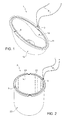
Figure 1 schematically illustrates a first light permeable cover for an aircraft's external light along with a monitoring system according to a preferred embodiment of the present invention for monitoring said first light permeable cover; -
Figure 2 schematically illustrates a second light permeable cover for an aircraft's external light, which second light permeable cover, while being different from the first light permeable cover ofFigure 1 , is coupled with the same monitoring system ofFigure 1 to be monitored by the latter; and -
Figures 3-6 schematically illustrate results of experimental tests carried out by the Applicant on two different external light covers under perfect integrity conditions and under impaired integrity conditions. - The following discussion is presented to enable a person skilled in the art to make and use the invention. Various modifications to the embodiments will be readily apparent to those skilled in the art, without departing from the scope of the present invention as claimed. Thus, the present invention is not intended to be limited to the embodiments shown and described, but is to be accorded the widest scope consistent with the principles and features disclosed herein and defined in the appended claims.
- The present invention relates to a system for monitoring a light permeable cover of a light or lamp.
- As previously explained, the present invention will be described in the following, only for the sake of simplicity and without losing generality, by making specific reference to external lights of an aircraft (such as an airplane, a helicopter, etc.), remaining it clear that the present invention can be advantageously exploited, without any substantial modification, also with external lamps of a generic means of transport (such as a train) or vehicle (such as a car), or, more in general, with any kind of light or lamp including a light permeable cover.
- For a better understanding of the present invention, reference is made to
Figures 1 and 2 , which schematically show a monitoring system according to a preferred embodiment of the present invention, which monitoring system is designed to monitor: - in the example shown in
Figure 1 , a first light permeable cover 1 of an external light or lamp of an aircraft; and - in the example shown in
Figure 2 , a second lightpermeable cover 2 of an external light or lamp of an aircraft, which second lightpermeable cover 2 has a shape different from the one of the first light permeable cover 1. - In particular, the first light permeable cover 1 shown in
Figure 1 is a domed or cap-shaped cover, specifically with a sort of egg-shell-like shape, while the second lightpermeable cover 2 shown inFigure 2 is a domed or cap-shaped cover, specifically with a sort of cup-like shape. - In detail, each of the
covers 1 and 2 comprises: - a respective closed peripheral rim or edge 11 or 21 designed to be fastened, or fixed, to an aircraft's external light or lamp (not shown in
Figures 1 and 2 for the sake of illustration simplicity); - a respective
external surface cover 1 or 2 is fastened/fixed to an aircraft's external light or lamp, is exposed to the external surrounding environment; and - a respective
internal surface cover 1 or 2 is fastened/fixed to an aircraft's external light or lamp, faces a light-emitting device of said aircraft's external light. - Conveniently, the
covers 1 and 2 are transparent and can be made of polycarbonate. - As shown in
Figures 1 and 2 , the monitoring system includes: - a
field source 3, which is- arranged at a respective position on the closed peripheral rim/
edge - is operable to emit a field through the closed peripheral rim/
edge cover 1 or 2 between theexternal surface internal surface cover 1 or 2 being guided by the latter, and - is conveniently connected to driving means 4 (which, in
Figures 1 and 2 , are represented in the form of wires) to be power-supplied and operated there through; and
- arranged at a respective position on the closed peripheral rim/
- a
sensor 5, which is- arranged at a respective position on the closed peripheral rim/
edge field source 3, - is designed to receive the field emitted by the
field source 3 and propagated inside thecover 1 or 2 up to saidsensor 5, and - is configured to measure intensity of the received field.
- arranged at a respective position on the closed peripheral rim/
- For the sake of clarity, it is worth noting that, during operation, the field is emitted by the
field source 3 inside the cover 1 or 2 (i.e., inside the cover's body extending from the closed peripheral rim/edge external surface internal surface 13 or 23) and, thence, not in the hollow defined by theinternal surface cover 1 or 2 acts as a "field guide" which guides the propagation of the field emitted by thefield source 3 inside saidcover 1 or 2. - Moreover, the monitoring system further includes detection means (not shown in
Figures 1 and 2 for the sake of illustration simplicity) configured to check integrity of thecover 1 or 2 and to detect a damage affecting light permeability (or, conveniently, transparency) of saidcover 1 or 2 on the basis of one or more field intensities measured by thesensor 5. - In particular, according to a first preferred embodiment of the present invention, the
sensor 5 and the detection means can be conveniently integrated into a first monitoring unit (not shown inFigures 1 and 2 for the sake of illustration simplicity), which further comprises wireless communication means (not shown inFigures 1 and 2 for the sake of illustration simplicity) configured to remotely communicate with a control device (not shown inFigures 1 and 2 for the sake of illustration simplicity) to wirelessly transmit to the latter data related to the field intensities measured by thesensor 5 and alarms related to the damages detected by the detection means. - Said control device can conveniently be a user terminal (for example, a hand-held, or portable, user terminal) designed to be used by a maintenance operator to retrieve from the monitoring unit the data related to the field intensities measured by the
sensor 5 and the alarms related to the damages detected by the detection means, or it can be a central control device which is installed on board the aircraft and is configured to: - collect, from each first monitoring unit according to the aforesaid first preferred embodiment of the present invention coupled with a respective cover of an external light of the aircraft, the data related to the field intensities measured by the
respective sensor 5 of said first monitoring unit and the alarms related to the damages detected by the respective detection means of said first monitoring unit; and - wirelessly transmit all the collected data and alarms to a user terminal (for example, a hand-held, or portable, user terminal) designed to be used by a maintenance operator.
- In other words, according to the aforesaid first preferred embodiment of the present invention, the first monitoring unit, which includes both the
sensor 5 and the detection means, is designed to perform the damage detection and to generate monitoring-related data (in particular, data related to the field intensities measured by thesensor 5 and alarms related to the damages detected by the detection means) and to transmit, by means of wireless communication means, said monitoring-related data to: - a user terminal designed to be used by a maintenance operator; or
- a central control device installed on board the aircraft.
- In this way, the damage detection is performed in a decentralized fashion (namely, for each monitored cover, the damage detection is performed by dedicated detection means of a corresponding first monitoring unit coupled with said monitored cover), and the monitoring-related data from all the first monitoring units installed on one and the same aircraft are:
- collected by a user terminal designed to be used by a maintenance operator; or
- collected by a central control device installed on board the aircraft and, when necessary, wirelessly transmitted from said central control device to a user terminal designed to be used by a maintenance operator.
- Instead, according to a second preferred embodiment of the present invention, the
sensor 5 can be conveniently integrated along with wireless communication means into a second monitoring unit (which, in this case, does not comprise the detection means), wherein said wireless communication means are configured to wirelessly transmit data related to the field intensities measured by thesensor 5 to: - a user terminal (for example, a hand-held, or portable, user terminal), which is designed to be used by a maintenance operator and comprises the detection means; or
- a central control device, which is installed on board the aircraft, comprises the detection means, and is further configured to wirelessly transmit the collected data and also alarms related to damages detected by the detection means to a user terminal (for example, a hand-held, or portable, user terminal) designed to be used by a maintenance operator.
- In other words, according to the aforesaid second preferred embodiment of the present invention, the damage detection is performed in a centralized fashion (namely, for all the monitored covers, the damage detection is performed by a single detection device) by means of:
- a user terminal, which is designed to be used by a maintenance operator and comprises said single detection device; or
- a central control device, which is installed on board the aircraft, comprises said single detection device, and is configured to, when necessary, wirelessly transmit to a user terminal designed to be used by a maintenance operator
- the data related to the field intensities measured by the
sensors 5 of all the second monitoring units installed on the aircraft, and - also alarms related to damages detected by the single detection device.
- the data related to the field intensities measured by the
- Conveniently, in either one of the aforesaid preferred first and second embodiments, the wireless communications between the first/second monitoring unit(s) and the user terminal or the central control device, and between the central control device and the user terminal can be based on one or more wireless communication technologies, such as Bluetooth technology, Radio Frequency Identification (RFID) technology, and/or one or more wireless communication technologies for mobile phones and data terminals (based, for example, on one or more of the following standards: GSM, GPRS, EDGE, UMTS, HSPA, and LTE).
- In the following some aspects and features of the monitoring system according to the present invention will be described in detail, which aspects and features are applicable to both the aforesaid preferred first and second embodiments.
- Conveniently, the detection means are configured to:
- store reference data indicative of one or more reference conditions of integrity of the
cover 1 or 2; and - check integrity of the
covers 1 or 2 and detect a damage in saidcover 1 or 2 by comparing the field intensities measured by thesensor 5 with the reference data. - More conveniently, the reference data stored by the detection means can be indicative of:
- 1) one or more field intensities measured by the
sensor 5 under perfect integrity conditions of thecover 1 or 2, namely when saidcover 1 or 2 has never sustained a damage; and/or - 2) one or more field intensities measured by the
sensor 5 under admissible integrity conditions of thecover 1 or 2, namely when saidcover 1 or 2 has sustained one or more damages which does/do not strongly impair light permeability (or, conveniently, transparency) of saidcover 1 or 2; and/or - 3) one or more thresholds computed on the basis of the field intensity measurements specified at the preceding points 1) and/or 2).
- Alternatively, the detection means can comprise a classifier, which is trained on the basis of the field intensity measurements specified at the preceding points 1) and/or 2) (i.e., intensity measurements performed when said
cover 1 or 2 has never sustained a damage and/or has sustained one or more damages which does/do not strongly impair light permeability (or, conveniently, transparency) of said cover 1 or 2) to detect a damage in saidcover 1 or 2. - As for arrangement of the
field source 3 and of thesensor 5, it is worth noting that, as shown inFigure 1 , the closedperipheral rim 11 of the cover 1 lies on a plane where substantially defines an ellipse, and thefield source 3 and thesensor 5 are arranged, each, at a respective end of the minor axis of said ellipse. - Instead, as shown in
Figure 2 , the closedperipheral rim 21 of thecover 2 lies on a plane where substantially defines a circumference/circle, and thefield source 3 and thesensor 5 are arranged, each, at a respective end of one and the same diameter of said circumference/circle. - Therefore, in more general terms, the closed peripheral rim is conveniently symmetrical with respect to an axis of symmetry (major/minor axis of the ellipse-shaped
rim 11 and any diameter of the circumference/circle-shaped rim 21), and thefield source 3 and the sensor 4 are conveniently arranged on the closed peripheral rim at positions that are substantially symmetrical with respect to said axis of symmetry. Moreover, if the closed peripheral rim does not lie on a single plane, the closed peripheral rim is conveniently symmetrical with respect to a plane of symmetry, and thefield source 3 and the sensor 4 are conveniently arranged on the closed peripheral rim at positions that are substantially symmetrical with respect to said plane of symmetry. - Preferably, the
field source 3 is a light source (for example based on LED technology) configured to emit an electromagnetic field or radiation with wavelength comprised in the visible or infrared range; accordingly, thesensor 5 is a photosensor or photodetector (for example a photodiode) configured to measure intensity of the electromagnetic field/radiation emitted by thelight source 3 and propagated inside the cover 1 or- 2 up to said photosensor/photodetector 5. - Alternatively, the
field source 3 can be an acoustic source configured to emit an acoustic field or wave; accordingly, thesensor 5 is an acoustic sensor configured to measure intensity of the acoustic field/wave emitted by theacoustic source 3 and propagated inside thecover 1 or 2 up to saidacoustic sensor 5. - In other words, the present invention advantageously exploits guiding properties of spatial curvature (geodesic) of the
cover 1 or 2 and its material dispersion properties. In fact, thecover 1 or 2 is designed to guide the visible/infrared light radiation emitted by thelight source 3, or the acoustic wave emitted by theacoustic source 3, to geometrically-defined points with an intensity that depends of the integrity state of saidcover 1 or 2. As is known, the guiding properties of the spatial curvature of a surface of a volume can be obtained either by a differential curvature change with constant refractive index, or by a constant curvature with variable refractive index. - Therefore, a reduction in the intensity measured by the
sensor 5 with respect to the reference data is directly related to a deterioration of the integrity of the cover 1 or 2 (for example due to one or more damages sustained by said cover 1 or 2) and, thence, to a reduction in the light permeability (or, conveniently, in the transparency) of saidcover 1 or 2. - Since there is a correlation among the wavelength of the field emitted by the
field source 3, the arrangement of thefield source 3 and of thesensor 5, and the spatial curvature of thecover 1 or 2, all these elements can be conveniently optimized, by means of an optical simulation, for enhancing sensitivity and accuracy of thesensor 5 and of the detection means. - The Applicant has carried out several experimental simulations and tests in order to evaluate performance, efficiency and reliability of the monitoring system according to the present invention. Results of some of the experimental simulations and tests carried out by the Applicant are presented in
Figures 3-6 . - In particular,
Figures 3-6 show the results of tests performed on two different external light covers under perfect integrity conditions (i.e., when the two covers have no damage) and under impaired integrity conditions (i.e., when the two covers are damaged, specifically they are scratched). - In detail,
Figures 3 and 4 shows the results of experimental tests carried out, respectively, on a cylindrical, perfectly transparent cover without any damage, and on the same cover damaged by scratches. Said tests were performed by: - using a
field source 3 in the form of a light source and asensor 5 in the form of a photosensor; - arranging the light source at the bottom left region shown in
Figures 3 and 4 , and the photosensor at the upper right region shown inFigures 3 and 4 ; and - capturing the light emitted by the light source and propagating inside the cover under test by means of a CCD camera,_i.e., a camera based on Charge-Coupled Device (CCD) technology.
- From-
Figure 3 it can be seen that the light is substantially concentrated in the region where the photosensor is arranged (i.e., upper right region shown inFigure 3 ), while fromFigure 4 it can be seen that the light is scattered substantially from all the scratched cover under test thereby reducing light intensity measurable/measured by the photosensor. - Moreover,
Figures 5 and 6 shows the results of experimental tests carried out, respectively, on a ellipsoidal, perfectly transparent cover without any damage, and on the same cover damaged by scratches. Said tests were performed by: - again using a
field source 3 in the form of a light source and asensor 5 in the form of a photosensor; - arranging the light source at the bottom region shown in
Figures 5 and 6 , and the photosensor at the upper region shown inFigures 5 and 6 ; and - again capturing the light emitted by the light source and propagating inside the cover under test by means of a CCD camera.
- From
Figure 5 it can be seen that the light is substantially concentrated in the region where the photosensor is arranged (i.e., upper region shown inFigure 5 ), while fromFigure 6 it can be seen that the light is scattered substantially from all the scratched cover under test thereby reducing light intensity measurable/measured by the photosensor. - The results shown in
Figures 3-6 confirm that: - the amount of field intensity measured by the sensor 5 (in particular, in the examples shown in
Figures 3-6 , the amount of light intensity measured by the photosensor) is directly related to the integrity state of the monitored cover and, accordingly, to the light permeability (in particular, the transparency) of said cover; and, thence, - a reduction in light permeability (in particular, a loss of transparency) of the monitored cover (for example, due to damages) results in a corresponding reduction in the field intensity measured by the sensor 5 (in particular, in the examples shown in
Figures 3-6 , a corresponding reduction in the light intensity measured by the photosensor). - Therefore, the monitoring system according to the present invention enables:
- light permeability (or, conveniently, transparency) of an external cover of a light or lamp to be monitored and objectively quantified; and
- a reduction in light permeability (or, conveniently, transparency) to be detected and, again, objectively quantified.
- From the foregoing, technical advantages of the present invention are immediately clear.
- In particular, it is worth noting that the monitoring system according to the present invention enables a constant monitoring and checking of integrity and, thence, of light permeability (or, conveniently, transparency) of an external cover of a light or lamp to be carried out with an efficiency and a reliability increased with respect to the ones of the current monitoring and checking methodologies based on subjective assessments of human operators.
- Moreover, it is important to stress the fact that the monitoring system according to the present invention invention enables light permeability (or, conveniently, transparency) to be monitored and objectively quantified, and any reduction in light permeability (or, conveniently, transparency) to be detected and objectively quantified.
- Therefore, with specific reference to the avionics sector, the monitoring system according to the present invention enables the safety-critical parameter represented by the integrity/light-permeability/transparency of a cover of an aircraft's external light to be monitored efficiently, reliably and constantly, thereby meeting the more and more demanding avionics requirements concerning safety and maintenance.
- Moreover, the monitoring system according to the present invention enables monitoring-related data to be wirelessly transmitted to maintenance teams, thereby achieving a time-saving, cost-saving, simplified and precise monitoring of the covers of the external lights of an aircraft and, thence, improving safety.
- The monitoring system according to the present invention works very well with excellent sensitivity and accuracy. In fact, an abrasion equivalent to a loss of about 50% of transparency reduces the measured field intensity by about one order of magnitude.
- Additionally, the monitoring system according to the present invention exploits a field source and a sensor directly arranged on, or embedded in, the cover to be monitored, thereby resulting in an extremely compact and sound system architecture.
- Finally, the present invention provides also an economic advantage. In fact, new external lights for aircrafts can be manufactured by embedding in said lights the monitoring system according to the present invention, thereby obtaining high added-value products to be sold.
- In conclusion, it is clear that numerous modifications and variants can be made to the present invention, all falling within the scope of the invention, as defined in the appended claims.
- In this respect, it is worth noting once again that the present invention can be advantageously exploited, without any substantial modification, with external lights or lamps of an aircraft (such as an airplane or a helicopter), of a generic means of transport (such as a train), of a vehicle (such as a car), or, more in general, with any kind of light or lamp including a light permeable cover.
Claims (19)
- Monitoring system for monitoring a light permeable cover (1;2) of a light or lamp, wherein said light permeable cover (1;2) includes:• a closed peripheral rim (11;21) designed to be fixed to a light or lamp;• an external surface (12;22) designed to be exposed to an external surrounding environment; and• an internal surface (13;23) designed to face a light-emitting device of the light or lamp;the monitoring system being characterized by comprising:• a field source (3), which is arranged at a first position on the closed peripheral rim (11;21) of the light permeable cover (1;2), and which is configured to emit a field inside the light permeable cover (1;2) between the internal (13;23) and external (12;22) surfaces so that the emitted field propagates inside said light permeable cover (1;2) being guided by the latter;• a sensor (5), which is arranged at a second position on the closed peripheral rim (11;21) of the light permeable cover (1;2), and which is configured to receive the field emitted by the field source (3) and propagated inside the light permeable cover (1;2) up to said sensor (5) and to measure intensity of the received field; wherein said first and second positions are different; and• detection means configured to check integrity of the light permeable cover (1;2) and to detect a damage affecting light permeability of said cover (1;2) on the basis of one or more field intensities measured by the sensor (5).
- The monitoring system of claim 1, wherein the closed peripheral rim (11;21) of the light permeable cover (1;2) is symmetrical with respect to an axis or plane of symmetry; and wherein the first and second positions are symmetrical with respect to said axis or plane of symmetry.
- The monitoring system according to claim 1 or 2, wherein the field source (3) is:• a light source configured to emit an electromagnetic field with wavelength comprised in the visible or infrared range; or• an acoustic source configured to emit an acoustic field.
- The monitoring system according to any claim 1-3, wherein the detection means are configured to check integrity of the light permeable cover (1;2) and to detect a damage affecting light permeability of said cover (1;2) on the basis of:• a field intensity measured by the sensor (5); and• reference data indicative of one or more reference conditions of integrity of the light permeable cover (1;2).
- The monitoring system of claim 4, wherein the reference data are indicative of at least one field intensity measured by the sensor (5) under at least one reference condition of integrity of the light permeable cover (1;2).
- The monitoring system of claim 4, wherein the reference data are indicative of field intensities measured by the sensor (5) under different reference conditions of integrity of the light permeable cover (1;2).
- The monitoring system of claim 4, wherein the reference data comprise at least one threshold computed on the basis of at least one field intensity measured by the sensor (5) under at least one reference condition of integrity of the light permeable cover (1;2).
- The monitoring system of claim 4, wherein the reference data comprise one or more thresholds computed on the basis of field intensities measured by the sensor (5) under different reference conditions of integrity of the light permeable cover (1;2).
- The monitoring system according to any claim 4-8, wherein the detection means are configured to:• store the reference data; and• check integrity of the light permeable cover (1;2) and detect a damage affecting light permeability of said cover (1;2) by comparing a field intensity measured by the sensor (5) with the stored reference data.
- The monitoring system according to any claim 4-6, wherein the detection means comprise a classifier, which is trained on the basis of the reference data to detect a damage affecting light permeability of the cover (1;2).
- The monitoring system according to any preceding claim, further comprising a control device; and wherein the sensor (5) is integrated, along with wireless communication means, into a monitoring unit, which is configured to wirelessly transmit, by means of said wireless communication means, monitoring-related data indicative of one or more field intensities measured by the sensor (5) to the control device.
- The monitoring system of claim 11, wherein the monitoring unit comprises also the detection means; and wherein, if the detection means detect a damage, the monitoring-related data are also indicative of an alarm related to said detected damage.
- The monitoring system of claim 11, wherein the control device comprises the detection means, which are configured to check integrity of the light permeable cover (1;2) and to detect a damage affecting light permeability of said cover (1;2) on the basis of the monitoring-related data received from the monitoring unit.
- The monitoring system according to any claim 11-13, wherein the control device is:• a user terminal designed to be used by a maintenance operator; or• a central control device, which is designed to- collect monitoring-related data from one or more monitoring units, and- wirelessly transmit the collected data to a user terminal designed to be used by a maintenance operator.
- Light permeable cover (1;2) for a light or lamp, including:• a closed peripheral rim (11;21) designed to be fixed to a light or lamp;• an external surface (12;22) designed to be exposed to an external surrounding environment;• an internal surface (13;23) designed to face a light-emitting device of the light or lamp; and• the monitoring system claimed in any preceding claim.
- Light comprising:• a housing body;• a light-emitting device fixed to the housing body;• a light permeable cover (1;2), which includes- a closed peripheral rim (11;21) fixed to the housing body,- an external surface (12;22) exposed to an external surrounding environment, and- an internal surface (13;23) facing the light-emitting device; and• the monitoring system claimed in any claim 1-14.
- Aircraft comprising the light claimed in claim 16.
- Means of transport comprising the light claimed in claim 16.
- Vehicle comprising the light claimed in claim 16.
Priority Applications (3)
| Application Number | Priority Date | Filing Date | Title |
|---|---|---|---|
| EP14425086.7A EP2960643B1 (en) | 2014-06-27 | 2014-06-27 | System for monitoring a light transparent cover of a light or lamp, especially of an aircraft's external light |
| RU2015125292A RU2693509C2 (en) | 2014-06-27 | 2015-06-25 | Control system of headlight or lamp translucent cap, especially aircraft external head lamp |
| CN201510369878.7A CN105222989B (en) | 2014-06-27 | 2015-06-29 | System for monitoring the euphotic cover of the outer lamp of lamp or lamps and lanterns, especially aircraft |
Applications Claiming Priority (1)
| Application Number | Priority Date | Filing Date | Title |
|---|---|---|---|
| EP14425086.7A EP2960643B1 (en) | 2014-06-27 | 2014-06-27 | System for monitoring a light transparent cover of a light or lamp, especially of an aircraft's external light |
Publications (2)
| Publication Number | Publication Date |
|---|---|
| EP2960643A1 true EP2960643A1 (en) | 2015-12-30 |
| EP2960643B1 EP2960643B1 (en) | 2019-03-13 |
Family
ID=51383688
Family Applications (1)
| Application Number | Title | Priority Date | Filing Date |
|---|---|---|---|
| EP14425086.7A Active EP2960643B1 (en) | 2014-06-27 | 2014-06-27 | System for monitoring a light transparent cover of a light or lamp, especially of an aircraft's external light |
Country Status (3)
| Country | Link |
|---|---|
| EP (1) | EP2960643B1 (en) |
| CN (1) | CN105222989B (en) |
| RU (1) | RU2693509C2 (en) |
Cited By (7)
| Publication number | Priority date | Publication date | Assignee | Title |
|---|---|---|---|---|
| WO2017178049A1 (en) * | 2016-04-13 | 2017-10-19 | Hewlett-Packard Development Company, L.P., | Defect detection |
| WO2018178908A1 (en) * | 2017-03-29 | 2018-10-04 | Zodiac Cabin Controls Gmbh | Aircraft lighting systems and methods |
| WO2019206596A1 (en) * | 2018-04-27 | 2019-10-31 | Robert Bosch Gmbh | Method for detecting damage and/or contamination on a transparent cover material of an optoelectronic sensor, system, optoelectronic sensor and means of transportation |
| US10734946B2 (en) | 2018-04-05 | 2020-08-04 | Alliance For Sustainable Energy, Llc | Methods and systems for determining soiling on photovoltaic devices |
| CN112165755A (en) * | 2020-09-30 | 2021-01-01 | 汤涛 | Building brightening intelligent control management system based on big data |
| EP3812285A1 (en) * | 2019-10-25 | 2021-04-28 | Goodrich Lighting Systems GmbH | Combined aircraft navigation and anti-collision light, and method of determining a state of erosion of a lens cover of a combined aircraft navigation and anti-collision light |
| US20240059427A1 (en) * | 2022-08-18 | 2024-02-22 | Goodrich Lighting Systems GmbH & Co. KG | Exterior aircraft light, aircraft comprising an exterior aircraft light, and method for providing an extent of erosion of an exterior surface of a light transmissive cover of an exterior aircraft light |
Citations (7)
| Publication number | Priority date | Publication date | Assignee | Title |
|---|---|---|---|---|
| US6196704B1 (en) * | 1998-04-25 | 2001-03-06 | Reitter & Schefenacker Gmbh | Light, especially tail light, for a motor vehicle |
| DE10358199B3 (en) * | 2003-12-12 | 2005-05-25 | Leoni Ag | Device for detecting fouling on object surfaces in Xenon headlamps for motor vehicles has optical element directly integrated into object surface without cover, at least one coupling point for coupling light in and/or out of optical element |
| DE102004032047A1 (en) * | 2004-06-30 | 2006-02-09 | Carsten Buhtz | Glass sheet inspection procedure for building applications measures light reflected from cracks and damage whilst guided within layer |
| US20110018439A1 (en) * | 2007-12-28 | 2011-01-27 | Francesco Fabbri | Anti-collision light for aircraft |
| US20110261577A1 (en) | 2008-06-23 | 2011-10-27 | Carsten Kohlmeier-Beckmann | Warning lamp for an aircraft |
| EP2450279A1 (en) | 2010-11-05 | 2012-05-09 | Sirio Panel S.P.A. | LED lighting device of an aircraft, in particular for manoeuvres of landing, take-off, taxiing, and searching, and aircraft comprising said device |
| US20130249375A1 (en) * | 2012-03-21 | 2013-09-26 | George W. Panagotacos | Anti-icing solid state aircraft lamp assembly with defroster apparatus, system, and method |
-
2014
- 2014-06-27 EP EP14425086.7A patent/EP2960643B1/en active Active
-
2015
- 2015-06-25 RU RU2015125292A patent/RU2693509C2/en active
- 2015-06-29 CN CN201510369878.7A patent/CN105222989B/en active Active
Patent Citations (7)
| Publication number | Priority date | Publication date | Assignee | Title |
|---|---|---|---|---|
| US6196704B1 (en) * | 1998-04-25 | 2001-03-06 | Reitter & Schefenacker Gmbh | Light, especially tail light, for a motor vehicle |
| DE10358199B3 (en) * | 2003-12-12 | 2005-05-25 | Leoni Ag | Device for detecting fouling on object surfaces in Xenon headlamps for motor vehicles has optical element directly integrated into object surface without cover, at least one coupling point for coupling light in and/or out of optical element |
| DE102004032047A1 (en) * | 2004-06-30 | 2006-02-09 | Carsten Buhtz | Glass sheet inspection procedure for building applications measures light reflected from cracks and damage whilst guided within layer |
| US20110018439A1 (en) * | 2007-12-28 | 2011-01-27 | Francesco Fabbri | Anti-collision light for aircraft |
| US20110261577A1 (en) | 2008-06-23 | 2011-10-27 | Carsten Kohlmeier-Beckmann | Warning lamp for an aircraft |
| EP2450279A1 (en) | 2010-11-05 | 2012-05-09 | Sirio Panel S.P.A. | LED lighting device of an aircraft, in particular for manoeuvres of landing, take-off, taxiing, and searching, and aircraft comprising said device |
| US20130249375A1 (en) * | 2012-03-21 | 2013-09-26 | George W. Panagotacos | Anti-icing solid state aircraft lamp assembly with defroster apparatus, system, and method |
Cited By (11)
| Publication number | Priority date | Publication date | Assignee | Title |
|---|---|---|---|---|
| WO2017178049A1 (en) * | 2016-04-13 | 2017-10-19 | Hewlett-Packard Development Company, L.P., | Defect detection |
| WO2018178908A1 (en) * | 2017-03-29 | 2018-10-04 | Zodiac Cabin Controls Gmbh | Aircraft lighting systems and methods |
| US11142338B2 (en) | 2017-03-29 | 2021-10-12 | Zodiac Cabin Controls Gmbh | Aircraft lighting systems and methods |
| US10734946B2 (en) | 2018-04-05 | 2020-08-04 | Alliance For Sustainable Energy, Llc | Methods and systems for determining soiling on photovoltaic devices |
| WO2019206596A1 (en) * | 2018-04-27 | 2019-10-31 | Robert Bosch Gmbh | Method for detecting damage and/or contamination on a transparent cover material of an optoelectronic sensor, system, optoelectronic sensor and means of transportation |
| EP3812285A1 (en) * | 2019-10-25 | 2021-04-28 | Goodrich Lighting Systems GmbH | Combined aircraft navigation and anti-collision light, and method of determining a state of erosion of a lens cover of a combined aircraft navigation and anti-collision light |
| US11225336B2 (en) | 2019-10-25 | 2022-01-18 | Goodrich Lighting Systems Gmbh | Combined aircraft navigation and anti-collision light, and method of determining a state of erosion of a lens cover of a combined aircraft navigation and anti-collision light |
| CN112165755A (en) * | 2020-09-30 | 2021-01-01 | 汤涛 | Building brightening intelligent control management system based on big data |
| CN112165755B (en) * | 2020-09-30 | 2021-08-13 | 厦门联发智能科技股份有限公司 | Building brightening intelligent control management system based on big data |
| US20240059427A1 (en) * | 2022-08-18 | 2024-02-22 | Goodrich Lighting Systems GmbH & Co. KG | Exterior aircraft light, aircraft comprising an exterior aircraft light, and method for providing an extent of erosion of an exterior surface of a light transmissive cover of an exterior aircraft light |
| US12054284B2 (en) * | 2022-08-18 | 2024-08-06 | Goodrich Lighting Systems GmbH & Co. KG | Exterior aircraft light, aircraft comprising an exterior aircraft light, and method for providing an extent of erosion of an exterior surface of a light transmissive cover of an exterior aircraft light |
Also Published As
| Publication number | Publication date |
|---|---|
| RU2693509C2 (en) | 2019-07-03 |
| RU2015125292A3 (en) | 2018-12-26 |
| CN105222989B (en) | 2019-11-05 |
| RU2015125292A (en) | 2017-01-10 |
| EP2960643B1 (en) | 2019-03-13 |
| CN105222989A (en) | 2016-01-06 |
Similar Documents
| Publication | Publication Date | Title |
|---|---|---|
| EP2960643B1 (en) | System for monitoring a light transparent cover of a light or lamp, especially of an aircraft's external light | |
| KR101696751B1 (en) | Safety cap with multi-function and safety supervision system in work | |
| EP2824460B1 (en) | System and method for detecting turbulence based upon observations of light scintillation | |
| CN106945843B (en) | Aircraft exterior light unit and aircraft comprising said unit | |
| EP3073249B1 (en) | Erosion detector for an exterior aircraft lighting device and exterior aircraft lighting device comprising the same | |
| CA2742916C (en) | Wide-band electromagnetic field detector and analysis system for aircraft | |
| EP2993130B1 (en) | Signal light and method of manufacture | |
| EP3495776B1 (en) | Mounting device adapter in a system for displaying mission critical information on an uncertified display | |
| JP2015050739A (en) | Monitor system, notification device, monitoring method | |
| US20180108187A1 (en) | System and method for detecting radome damage | |
| KR101671993B1 (en) | Safety system for vehicle | |
| CN102939528A (en) | Sensor for determining the roadway condition without contact and use thereof | |
| CN105992941B (en) | Ice and subcooled water detection system | |
| ES2969998T3 (en) | Fiber Optic Temperature Sensors in a Distributed Smoke Detection System | |
| CN110703796B (en) | Comprehensive control system based on unmanned aerial vehicle supervision | |
| CN103738704B (en) | A kind of transport tape for safety check | |
| CN211427155U (en) | Based on unmanned aerial vehicle supervision integrated control system | |
| CN106530822B (en) | A kind of vehicle monitoring method and system | |
| CN207816818U (en) | The mist sensor and motor vehicle of a kind of motor vehicle for being moved on road surface | |
| CN109100806A (en) | A kind of hierarchical detection method and device | |
| JP2017190545A (en) | Helmet with LED | |
| KR101378396B1 (en) | Portable instrument for optical testing of lamps | |
| CN204926446U (en) | Tunnel lamp with digit location and orientation | |
| US11946805B2 (en) | Spectrometer apparatus and a corresponding method for operating a spectrometer apparatus | |
| CN209148149U (en) | A kind of track traffic signal machine luminance detection device |
Legal Events
| Date | Code | Title | Description |
|---|---|---|---|
| PUAI | Public reference made under article 153(3) epc to a published international application that has entered the european phase |
Free format text: ORIGINAL CODE: 0009012 |
|
| AK | Designated contracting states |
Kind code of ref document: A1 Designated state(s): AL AT BE BG CH CY CZ DE DK EE ES FI FR GB GR HR HU IE IS IT LI LT LU LV MC MK MT NL NO PL PT RO RS SE SI SK SM TR |
|
| AX | Request for extension of the european patent |
Extension state: BA ME |
|
| 17P | Request for examination filed |
Effective date: 20160628 |
|
| RBV | Designated contracting states (corrected) |
Designated state(s): AL AT BE BG CH CY CZ DE DK EE ES FI FR GB GR HR HU IE IS IT LI LT LU LV MC MK MT NL NO PL PT RO RS SE SI SK SM TR |
|
| STAA | Information on the status of an ep patent application or granted ep patent |
Free format text: STATUS: EXAMINATION IS IN PROGRESS |
|
| 17Q | First examination report despatched |
Effective date: 20180417 |
|
| GRAP | Despatch of communication of intention to grant a patent |
Free format text: ORIGINAL CODE: EPIDOSNIGR1 |
|
| STAA | Information on the status of an ep patent application or granted ep patent |
Free format text: STATUS: GRANT OF PATENT IS INTENDED |
|
| INTG | Intention to grant announced |
Effective date: 20181004 |
|
| RAP1 | Party data changed (applicant data changed or rights of an application transferred) |
Owner name: LEONARDO S.P.A. |
|
| GRAS | Grant fee paid |
Free format text: ORIGINAL CODE: EPIDOSNIGR3 |
|
| GRAA | (expected) grant |
Free format text: ORIGINAL CODE: 0009210 |
|
| STAA | Information on the status of an ep patent application or granted ep patent |
Free format text: STATUS: THE PATENT HAS BEEN GRANTED |
|
| AK | Designated contracting states |
Kind code of ref document: B1 Designated state(s): AL AT BE BG CH CY CZ DE DK EE ES FI FR GB GR HR HU IE IS IT LI LT LU LV MC MK MT NL NO PL PT RO RS SE SI SK SM TR |
|
| REG | Reference to a national code |
Ref country code: GB Ref legal event code: FG4D |
|
| REG | Reference to a national code |
Ref country code: CH Ref legal event code: EP Ref country code: AT Ref legal event code: REF Ref document number: 1108381 Country of ref document: AT Kind code of ref document: T Effective date: 20190315 |
|
| REG | Reference to a national code |
Ref country code: DE Ref legal event code: R096 Ref document number: 602014042742 Country of ref document: DE |
|
| REG | Reference to a national code |
Ref country code: IE Ref legal event code: FG4D |
|
| REG | Reference to a national code |
Ref country code: CH Ref legal event code: NV Representative=s name: HEPP WENGER RYFFEL AG, CH |
|
| REG | Reference to a national code |
Ref country code: SE Ref legal event code: TRGR |
|
| REG | Reference to a national code |
Ref country code: NL Ref legal event code: MP Effective date: 20190313 |
|
| REG | Reference to a national code |
Ref country code: LT Ref legal event code: MG4D |
|
| PG25 | Lapsed in a contracting state [announced via postgrant information from national office to epo] |
Ref country code: FI Free format text: LAPSE BECAUSE OF FAILURE TO SUBMIT A TRANSLATION OF THE DESCRIPTION OR TO PAY THE FEE WITHIN THE PRESCRIBED TIME-LIMIT Effective date: 20190313 Ref country code: NO Free format text: LAPSE BECAUSE OF FAILURE TO SUBMIT A TRANSLATION OF THE DESCRIPTION OR TO PAY THE FEE WITHIN THE PRESCRIBED TIME-LIMIT Effective date: 20190613 Ref country code: LT Free format text: LAPSE BECAUSE OF FAILURE TO SUBMIT A TRANSLATION OF THE DESCRIPTION OR TO PAY THE FEE WITHIN THE PRESCRIBED TIME-LIMIT Effective date: 20190313 |
|
| PG25 | Lapsed in a contracting state [announced via postgrant information from national office to epo] |
Ref country code: HR Free format text: LAPSE BECAUSE OF FAILURE TO SUBMIT A TRANSLATION OF THE DESCRIPTION OR TO PAY THE FEE WITHIN THE PRESCRIBED TIME-LIMIT Effective date: 20190313 Ref country code: NL Free format text: LAPSE BECAUSE OF FAILURE TO SUBMIT A TRANSLATION OF THE DESCRIPTION OR TO PAY THE FEE WITHIN THE PRESCRIBED TIME-LIMIT Effective date: 20190313 Ref country code: LV Free format text: LAPSE BECAUSE OF FAILURE TO SUBMIT A TRANSLATION OF THE DESCRIPTION OR TO PAY THE FEE WITHIN THE PRESCRIBED TIME-LIMIT Effective date: 20190313 Ref country code: GR Free format text: LAPSE BECAUSE OF FAILURE TO SUBMIT A TRANSLATION OF THE DESCRIPTION OR TO PAY THE FEE WITHIN THE PRESCRIBED TIME-LIMIT Effective date: 20190614 Ref country code: RS Free format text: LAPSE BECAUSE OF FAILURE TO SUBMIT A TRANSLATION OF THE DESCRIPTION OR TO PAY THE FEE WITHIN THE PRESCRIBED TIME-LIMIT Effective date: 20190313 Ref country code: BG Free format text: LAPSE BECAUSE OF FAILURE TO SUBMIT A TRANSLATION OF THE DESCRIPTION OR TO PAY THE FEE WITHIN THE PRESCRIBED TIME-LIMIT Effective date: 20190613 |
|
| REG | Reference to a national code |
Ref country code: AT Ref legal event code: MK05 Ref document number: 1108381 Country of ref document: AT Kind code of ref document: T Effective date: 20190313 |
|
| PG25 | Lapsed in a contracting state [announced via postgrant information from national office to epo] |
Ref country code: EE Free format text: LAPSE BECAUSE OF FAILURE TO SUBMIT A TRANSLATION OF THE DESCRIPTION OR TO PAY THE FEE WITHIN THE PRESCRIBED TIME-LIMIT Effective date: 20190313 Ref country code: RO Free format text: LAPSE BECAUSE OF FAILURE TO SUBMIT A TRANSLATION OF THE DESCRIPTION OR TO PAY THE FEE WITHIN THE PRESCRIBED TIME-LIMIT Effective date: 20190313 Ref country code: CZ Free format text: LAPSE BECAUSE OF FAILURE TO SUBMIT A TRANSLATION OF THE DESCRIPTION OR TO PAY THE FEE WITHIN THE PRESCRIBED TIME-LIMIT Effective date: 20190313 Ref country code: AL Free format text: LAPSE BECAUSE OF FAILURE TO SUBMIT A TRANSLATION OF THE DESCRIPTION OR TO PAY THE FEE WITHIN THE PRESCRIBED TIME-LIMIT Effective date: 20190313 Ref country code: ES Free format text: LAPSE BECAUSE OF FAILURE TO SUBMIT A TRANSLATION OF THE DESCRIPTION OR TO PAY THE FEE WITHIN THE PRESCRIBED TIME-LIMIT Effective date: 20190313 Ref country code: SK Free format text: LAPSE BECAUSE OF FAILURE TO SUBMIT A TRANSLATION OF THE DESCRIPTION OR TO PAY THE FEE WITHIN THE PRESCRIBED TIME-LIMIT Effective date: 20190313 Ref country code: PT Free format text: LAPSE BECAUSE OF FAILURE TO SUBMIT A TRANSLATION OF THE DESCRIPTION OR TO PAY THE FEE WITHIN THE PRESCRIBED TIME-LIMIT Effective date: 20190713 |
|
| PG25 | Lapsed in a contracting state [announced via postgrant information from national office to epo] |
Ref country code: PL Free format text: LAPSE BECAUSE OF FAILURE TO SUBMIT A TRANSLATION OF THE DESCRIPTION OR TO PAY THE FEE WITHIN THE PRESCRIBED TIME-LIMIT Effective date: 20190313 Ref country code: SM Free format text: LAPSE BECAUSE OF FAILURE TO SUBMIT A TRANSLATION OF THE DESCRIPTION OR TO PAY THE FEE WITHIN THE PRESCRIBED TIME-LIMIT Effective date: 20190313 |
|
| REG | Reference to a national code |
Ref country code: DE Ref legal event code: R097 Ref document number: 602014042742 Country of ref document: DE |
|
| PG25 | Lapsed in a contracting state [announced via postgrant information from national office to epo] |
Ref country code: AT Free format text: LAPSE BECAUSE OF FAILURE TO SUBMIT A TRANSLATION OF THE DESCRIPTION OR TO PAY THE FEE WITHIN THE PRESCRIBED TIME-LIMIT Effective date: 20190313 Ref country code: IS Free format text: LAPSE BECAUSE OF FAILURE TO SUBMIT A TRANSLATION OF THE DESCRIPTION OR TO PAY THE FEE WITHIN THE PRESCRIBED TIME-LIMIT Effective date: 20190713 |
|
| PLBE | No opposition filed within time limit |
Free format text: ORIGINAL CODE: 0009261 |
|
| STAA | Information on the status of an ep patent application or granted ep patent |
Free format text: STATUS: NO OPPOSITION FILED WITHIN TIME LIMIT |
|
| PG25 | Lapsed in a contracting state [announced via postgrant information from national office to epo] |
Ref country code: MC Free format text: LAPSE BECAUSE OF FAILURE TO SUBMIT A TRANSLATION OF THE DESCRIPTION OR TO PAY THE FEE WITHIN THE PRESCRIBED TIME-LIMIT Effective date: 20190313 Ref country code: DK Free format text: LAPSE BECAUSE OF FAILURE TO SUBMIT A TRANSLATION OF THE DESCRIPTION OR TO PAY THE FEE WITHIN THE PRESCRIBED TIME-LIMIT Effective date: 20190313 |
|
| 26N | No opposition filed |
Effective date: 20191216 |
|
| PG25 | Lapsed in a contracting state [announced via postgrant information from national office to epo] |
Ref country code: SI Free format text: LAPSE BECAUSE OF FAILURE TO SUBMIT A TRANSLATION OF THE DESCRIPTION OR TO PAY THE FEE WITHIN THE PRESCRIBED TIME-LIMIT Effective date: 20190313 |
|
| REG | Reference to a national code |
Ref country code: BE Ref legal event code: MM Effective date: 20190630 |
|
| PG25 | Lapsed in a contracting state [announced via postgrant information from national office to epo] |
Ref country code: TR Free format text: LAPSE BECAUSE OF FAILURE TO SUBMIT A TRANSLATION OF THE DESCRIPTION OR TO PAY THE FEE WITHIN THE PRESCRIBED TIME-LIMIT Effective date: 20190313 |
|
| PG25 | Lapsed in a contracting state [announced via postgrant information from national office to epo] |
Ref country code: IE Free format text: LAPSE BECAUSE OF NON-PAYMENT OF DUE FEES Effective date: 20190627 |
|
| PG25 | Lapsed in a contracting state [announced via postgrant information from national office to epo] |
Ref country code: LU Free format text: LAPSE BECAUSE OF NON-PAYMENT OF DUE FEES Effective date: 20190627 Ref country code: BE Free format text: LAPSE BECAUSE OF NON-PAYMENT OF DUE FEES Effective date: 20190630 |
|
| PG25 | Lapsed in a contracting state [announced via postgrant information from national office to epo] |
Ref country code: CY Free format text: LAPSE BECAUSE OF FAILURE TO SUBMIT A TRANSLATION OF THE DESCRIPTION OR TO PAY THE FEE WITHIN THE PRESCRIBED TIME-LIMIT Effective date: 20190313 |
|
| PG25 | Lapsed in a contracting state [announced via postgrant information from national office to epo] |
Ref country code: MT Free format text: LAPSE BECAUSE OF FAILURE TO SUBMIT A TRANSLATION OF THE DESCRIPTION OR TO PAY THE FEE WITHIN THE PRESCRIBED TIME-LIMIT Effective date: 20190313 Ref country code: HU Free format text: LAPSE BECAUSE OF FAILURE TO SUBMIT A TRANSLATION OF THE DESCRIPTION OR TO PAY THE FEE WITHIN THE PRESCRIBED TIME-LIMIT; INVALID AB INITIO Effective date: 20140627 |
|
| PG25 | Lapsed in a contracting state [announced via postgrant information from national office to epo] |
Ref country code: MK Free format text: LAPSE BECAUSE OF FAILURE TO SUBMIT A TRANSLATION OF THE DESCRIPTION OR TO PAY THE FEE WITHIN THE PRESCRIBED TIME-LIMIT Effective date: 20190313 |
|
| PGFP | Annual fee paid to national office [announced via postgrant information from national office to epo] |
Ref country code: CH Payment date: 20230702 Year of fee payment: 10 |
|
| PGFP | Annual fee paid to national office [announced via postgrant information from national office to epo] |
Ref country code: GB Payment date: 20240618 Year of fee payment: 11 |
|
| PGFP | Annual fee paid to national office [announced via postgrant information from national office to epo] |
Ref country code: DE Payment date: 20240627 Year of fee payment: 11 |
|
| PGFP | Annual fee paid to national office [announced via postgrant information from national office to epo] |
Ref country code: FR Payment date: 20240625 Year of fee payment: 11 |
|
| PGFP | Annual fee paid to national office [announced via postgrant information from national office to epo] |
Ref country code: SE Payment date: 20240624 Year of fee payment: 11 |
|
| PGFP | Annual fee paid to national office [announced via postgrant information from national office to epo] |
Ref country code: IT Payment date: 20240605 Year of fee payment: 11 |