EP2960432B1 - Rotor et moteur à turbine à gaz comprenant un rotor - Google Patents
Rotor et moteur à turbine à gaz comprenant un rotor Download PDFInfo
- Publication number
- EP2960432B1 EP2960432B1 EP15166116.2A EP15166116A EP2960432B1 EP 2960432 B1 EP2960432 B1 EP 2960432B1 EP 15166116 A EP15166116 A EP 15166116A EP 2960432 B1 EP2960432 B1 EP 2960432B1
- Authority
- EP
- European Patent Office
- Prior art keywords
- rotor
- radius
- disposed
- thickness
- rim
- Prior art date
- Legal status (The legal status is an assumption and is not a legal conclusion. Google has not performed a legal analysis and makes no representation as to the accuracy of the status listed.)
- Active
Links
- 230000005484 gravity Effects 0.000 claims description 7
- 238000002485 combustion reaction Methods 0.000 claims description 4
- 239000007789 gas Substances 0.000 description 27
- 230000005284 excitation Effects 0.000 description 10
- 239000000446 fuel Substances 0.000 description 7
- 239000000463 material Substances 0.000 description 6
- 230000008878 coupling Effects 0.000 description 5
- 238000010168 coupling process Methods 0.000 description 5
- 238000005859 coupling reaction Methods 0.000 description 5
- 230000004044 response Effects 0.000 description 4
- 230000007246 mechanism Effects 0.000 description 3
- 125000004122 cyclic group Chemical group 0.000 description 2
- 238000010586 diagram Methods 0.000 description 2
- 230000037406 food intake Effects 0.000 description 2
- 238000004519 manufacturing process Methods 0.000 description 2
- 230000010355 oscillation Effects 0.000 description 2
- 230000009467 reduction Effects 0.000 description 2
- 230000003068 static effect Effects 0.000 description 2
- 230000008859 change Effects 0.000 description 1
- 230000006835 compression Effects 0.000 description 1
- 238000007906 compression Methods 0.000 description 1
- 230000003292 diminished effect Effects 0.000 description 1
- 230000003467 diminishing effect Effects 0.000 description 1
- 230000000694 effects Effects 0.000 description 1
- 230000003993 interaction Effects 0.000 description 1
- 230000004048 modification Effects 0.000 description 1
- 238000012986 modification Methods 0.000 description 1
- 230000001737 promoting effect Effects 0.000 description 1
- 230000001902 propagating effect Effects 0.000 description 1
- 238000009877 rendering Methods 0.000 description 1
- 230000002459 sustained effect Effects 0.000 description 1
Images


Classifications
-
- F—MECHANICAL ENGINEERING; LIGHTING; HEATING; WEAPONS; BLASTING
- F01—MACHINES OR ENGINES IN GENERAL; ENGINE PLANTS IN GENERAL; STEAM ENGINES
- F01D—NON-POSITIVE DISPLACEMENT MACHINES OR ENGINES, e.g. STEAM TURBINES
- F01D5/00—Blades; Blade-carrying members; Heating, heat-insulating, cooling or antivibration means on the blades or the members
- F01D5/02—Blade-carrying members, e.g. rotors
- F01D5/027—Arrangements for balancing
-
- F—MECHANICAL ENGINEERING; LIGHTING; HEATING; WEAPONS; BLASTING
- F01—MACHINES OR ENGINES IN GENERAL; ENGINE PLANTS IN GENERAL; STEAM ENGINES
- F01D—NON-POSITIVE DISPLACEMENT MACHINES OR ENGINES, e.g. STEAM TURBINES
- F01D5/00—Blades; Blade-carrying members; Heating, heat-insulating, cooling or antivibration means on the blades or the members
- F01D5/02—Blade-carrying members, e.g. rotors
- F01D5/10—Anti- vibration means
-
- F—MECHANICAL ENGINEERING; LIGHTING; HEATING; WEAPONS; BLASTING
- F01—MACHINES OR ENGINES IN GENERAL; ENGINE PLANTS IN GENERAL; STEAM ENGINES
- F01D—NON-POSITIVE DISPLACEMENT MACHINES OR ENGINES, e.g. STEAM TURBINES
- F01D5/00—Blades; Blade-carrying members; Heating, heat-insulating, cooling or antivibration means on the blades or the members
- F01D5/12—Blades
- F01D5/14—Form or construction
- F01D5/16—Form or construction for counteracting blade vibration
-
- F—MECHANICAL ENGINEERING; LIGHTING; HEATING; WEAPONS; BLASTING
- F04—POSITIVE - DISPLACEMENT MACHINES FOR LIQUIDS; PUMPS FOR LIQUIDS OR ELASTIC FLUIDS
- F04D—NON-POSITIVE-DISPLACEMENT PUMPS
- F04D29/00—Details, component parts, or accessories
- F04D29/26—Rotors specially for elastic fluids
- F04D29/28—Rotors specially for elastic fluids for centrifugal or helico-centrifugal pumps for radial-flow or helico-centrifugal pumps
- F04D29/284—Rotors specially for elastic fluids for centrifugal or helico-centrifugal pumps for radial-flow or helico-centrifugal pumps for compressors
-
- F—MECHANICAL ENGINEERING; LIGHTING; HEATING; WEAPONS; BLASTING
- F04—POSITIVE - DISPLACEMENT MACHINES FOR LIQUIDS; PUMPS FOR LIQUIDS OR ELASTIC FLUIDS
- F04D—NON-POSITIVE-DISPLACEMENT PUMPS
- F04D29/00—Details, component parts, or accessories
- F04D29/66—Combating cavitation, whirls, noise, vibration or the like; Balancing
- F04D29/661—Combating cavitation, whirls, noise, vibration or the like; Balancing especially adapted for elastic fluid pumps
- F04D29/662—Balancing of rotors
-
- F—MECHANICAL ENGINEERING; LIGHTING; HEATING; WEAPONS; BLASTING
- F05—INDEXING SCHEMES RELATING TO ENGINES OR PUMPS IN VARIOUS SUBCLASSES OF CLASSES F01-F04
- F05D—INDEXING SCHEME FOR ASPECTS RELATING TO NON-POSITIVE-DISPLACEMENT MACHINES OR ENGINES, GAS-TURBINES OR JET-PROPULSION PLANTS
- F05D2250/00—Geometry
- F05D2250/70—Shape
- F05D2250/73—Shape asymmetric
-
- F—MECHANICAL ENGINEERING; LIGHTING; HEATING; WEAPONS; BLASTING
- F05—INDEXING SCHEMES RELATING TO ENGINES OR PUMPS IN VARIOUS SUBCLASSES OF CLASSES F01-F04
- F05D—INDEXING SCHEME FOR ASPECTS RELATING TO NON-POSITIVE-DISPLACEMENT MACHINES OR ENGINES, GAS-TURBINES OR JET-PROPULSION PLANTS
- F05D2260/00—Function
- F05D2260/96—Preventing, counteracting or reducing vibration or noise
Definitions
- the present disclosure relates generally to a gas turbine engine, and more specifically to a rotor for a gas turbine engine.
- rotary mechanisms are designed to direct a portion of the gas path to a secondary air system within the engine that is designed to prevent hot gas ingestion and to cool parts of the engine. If the air flow around the rotor is not adequately directed, insufficient pressurized air flow will be delivered to the secondary air system.
- US 2006/083619 discloses a rotor of an axial type having a balancing system including asymmetric rings.
- a further known rotor is disclosed in US 4 294 135 .
- a rotor defining an axis of rotation as set forth in claim 1.
- the rotor comprises an impeller within a gas turbine engine.
- the asymmetric rim comprises a balancing rim.
- the asymmetric rim comprises: a first segment including a first radially outer edge disposed at a first radius, a first radially inner edge disposed at a second radius; and a second segment including a second radially outer edge disposed at a third radius, a second radially inner edge disposed at a fourth radius; wherein the first radius is different than the third radius and the second radius is different than the fourth radius.
- a further embodiment of any of the above comprises a third segment including a third radially outer edge disposed at a fifth radius and a third radially inner edge disposed at a sixth radius.
- the asymmetric rim comprises: a first segment having a first thickness and a first center of gravity disposed at a first radius; a second segment having a second thickness and a second center of gravity disposed at the first radius; wherein the first thickness is different than the second thickness.
- the first segment includes a first thickness at the first radially outer edge that is greater than a second thickness at the first radially inner edge; and the second segment includes a third thickness at the second radially outer edge that is greater than a fourth thickness at the first radially inner edge.
- the first and second segments each include a surface including a forward edge and an aft edge, wherein the forward edge is disposed at a larger radius than the aft edge.
- a surface of the aft side radially outward of the asymmetric rim is disposed at an angle to a plane perpendicular to the axis of rotation such that a radially inner edge of the surface is forward of a radially outer edge of the surface.
- the angle comprises an angle between approximately one degree and approximately five degrees.
- an assembly for a gas turbine engine comprising: an engine component; and a rotor defining an axis of rotation as set forth above; wherein the component comprises one of a compressor section, a combustion section, a turbine section, and an exhaust section.
- the rotor comprises an impeller within a gas turbine engine.
- the asymmetric rim comprises a balancing rim.
- the asymmetric rim comprises: a first segment including a first radially outer edge disposed at a first radius, a first radially inner edge disposed at a second radius; and a second segment including a second radially outer edge disposed at a third radius, a second radially inner edge disposed at a fourth radius; wherein the first radius is different than the third radius and the second radius is different than the fourth radius.
- the asymmetric rim comprises: a first segment having a first thickness and a first center of gravity disposed at a first radius; a second segment having a second thickness and a second center of gravity disposed at the first radius; wherein the first thickness is different than the second thickness.
- the first segment includes a first thickness at the first radially outer edge that is greater than a second thickness at the first radially inner edge; and the second segment includes a third thickness at the second radially outer edge that is greater than a fourth thickness at the first radially inner edge.
- the first and second segments each include a surface including a forward edge and an aft edge, wherein the forward edge is disposed at a larger radius than the aft edge.
- a surface of the aft side radially outward of the asymmetric rim is disposed at an angle to a plane perpendicular to the axis of rotation such that a radially inner edge of the surface is forward of a radially outer edge of the surface.
- the angle comprises an angle between approximately one degree and approximately five degrees.
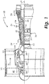
- FIG. 1 schematically illustrates a gas turbine engine 20.
- the gas turbine engine 20 is disclosed herein as a two-spool turbofan that generally incorporates a fan section 22, a compressor section 24, a combustor section 26 and a turbine section 28.
- Alternative engines might include an augmentor section (not shown) among other systems or features.
- the fan section 22 drives air along a bypass flow path B in a bypass duct, while the compressor section 24 drives air along a core flow path C for compression and communication into the combustor section 26 then expansion through the turbine section 28.
- the exemplary engine 20 generally includes a low speed spool 30 and a high speed spool 32 mounted for rotation about an engine central longitudinal axis A relative to an engine static structure 36 via several bearing systems 38. It should be understood that various bearing systems 38 at various locations may alternatively or additionally be provided, and the location of bearing systems 38 may be varied as appropriate to the application.
- the low speed spool 30 generally includes an inner shaft 40 that interconnects a fan 42, a low pressure compressor 44 and a low pressure turbine 46.
- the inner shaft 40 is connected to the fan 42 through a speed change mechanism, which in exemplary gas turbine engine 20 is illustrated as a geared architecture 48 to drive the fan 42 at a lower speed than the low speed spool 30.
- the high speed spool 32 includes an outer shaft 50 that interconnects a high pressure compressor 52 and high pressure turbine 54.
- a combustor 56 is arranged in exemplary gas turbine 20 between the high pressure compressor 52 and the high pressure turbine 54.
- An engine static structure 36 supports bearing systems 38 in the turbine section 28.
- the inner shaft 40 and the outer shaft 50 are concentric and rotate via bearing systems 38 about the engine central longitudinal axis A, which is collinear with their longitudinal axes.
- each of the positions of the fan section 22, compressor section 24, combustor section 26, turbine section 28, and fan drive gear system 48 may be varied.
- gear system 48 may be located aft of combustor section 26 or even aft of turbine section 28, and fan section 22 may be positioned forward or aft of the location of gear system 48.
- the engine 20 in one example is a high-bypass geared aircraft engine.
- the engine 20 bypass ratio is greater than about six (6), with an example embodiment being greater than about ten (10)
- the geared architecture 48 is an epicyclic gear train, such as a planetary gear system or other gear system, with a gear reduction ratio of greater than about 2.3
- the low pressure turbine 46 has a pressure ratio that is greater than about five.
- the engine 20 bypass ratio is greater than about ten (10:1)
- the fan diameter is significantly larger than that of the low pressure compressor 44
- the low pressure turbine 46 has a pressure ratio that is greater than about five 5:1.
- Low pressure turbine 46 pressure ratio is pressure measured prior to inlet of low pressure turbine 46 as related to the pressure at the outlet of the low pressure turbine 46 prior to an exhaust nozzle.
- the geared architecture 48 may be an epicycle gear train, such as a planetary gear system or other gear system, with a gear reduction ratio of greater than about 2.3:1. It should be understood, however, that the above parameters are only exemplary of one embodiment of a geared architecture engine and that the present invention is applicable to other gas turbine engines including direct drive turbofans.
- the fan section 22 of the engine 20 is designed for a particular flight condition -- typically cruise at about 0.8 Mach and about 35,000 feet (10,688 meters).
- the flight condition of 0.8 Mach and 35,000 ft. (10,688 meters), with the engine at its best fuel consumption - also known as "bucket cruise Thrust Specific Fuel Consumption ('TSFC')" - is the industry standard parameter of lbm of fuel being burned divided by lbf of thrust the engine produces at that minimum point.
- "Low fan pressure ratio” is the pressure ratio across the fan blade alone, without a Fan Exit Guide Vane (“FEGV”) system.
- the low fan pressure ratio as disclosed herein according to one non-limiting embodiment is less than about 1.45.
- "Low corrected fan tip speed” is the actual fan tip speed in ft/sec divided by an industry standard temperature correction of [(Tram °R) / (518.7 °R)] 0.5 .
- the "Low corrected fan tip speed” as disclosed herein according to one non-limiting embodiment is less than about 1150 ft / second (350.5 m/sec).
- a rotor component of a radial compressor is a compressor impeller with a series of main blades and splitter blades, an example of which is shown in FIG. 2A and indicated generally at 100.
- the compressor impeller 100 comprises a disc 102 carrying main blades 103 and splitter blades 105 that compress incoming air, which is directed through a diffuser to a combustion chamber, mixed with fuel and ignited.
- the turbine is propelled by rapidly expanding gases resulting from the combustion of the fuel and the compressed incoming air.
- the impeller can also be solely used to deliver compressed air to the aircraft cabin.
- the compressor impeller 100 is linked to, and powered by the turbine.
- the main blades 103 and splitter blades 105 coupled with the disc 102 can be subject to vibratory excitation at frequencies which coincide with integer multiples (referred to as harmonics) of the radial compressor's rotational frequency.
- the main blades 103, the splitter blades 105 and/or the disc 102 can undergo vibratory deflections that create vibratory stress on the blades 103/105. If the vibratory excitation occurs in an expected operating speed range of the radial compressor, the vibratory stresses can create high cycle fatigue of the impeller 100.
- a bladed disc like the impeller 100 is considered as a cyclically symmetric structure, consisting of a basic sector which possesses rotational symmetry. That is, the overall configuration, consisting of n cyclic sectors, is obtained after the basic sector is rotated about the axis of symmetry n times by a given angle defined as (360/n) degrees.
- the mechanical coupling between the disc 102 and blades 103/105 results in a complex coupled vibratory system, bearing dynamic characteristics of both blade and disc, and represents a combination of disc and blade oscillation at certain frequencies, called natural frequencies.
- the corresponding deflection modal-shape of the blade-disc system is characterized in terms of nodal diameter.
- a nodal diameter is a boundary line across the disc 102 diameter. The disc 102 structure lying on this line is stationary, while the rest of the structure vibrates in one direction on one side of this diametral line and in the opposite direction on the other side of the line.
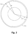
- FIG. 2C illustrates an example of a two nodal diameter coupling vibration of a cyclically symmetric impeller 100.
- the nodal lines 107 represent portions of the impeller 100 where there is no structural oscillation. Structural vibrations of opposite direction are located on the two sides of these nodal lines 107 (i.e., un-shaded areas).
- the two nodal lines 107 are normal to each other (i.e., they are at 90 degrees apart).
- N engine order (NE), where N is an integer, is defined as N times the engine operational speed of the engine.
- Engine vibration can result from forces generated by the rotation of an unbalanced rotor.
- balancing the rotor components minimizes these engine vibration forces.
- the balancing of a rotating component is performed through material removal.
- a balancing rim of sufficient mass for balancing is added to the back (aft) face of the impeller 100.
- the rotational balance of the impeller 100 is tested and material is removed from the balancing rim at locations that will result in the impeller 100 being balanced while rotating.
- the stiffness of the balancing rim affects the overall stiffness of the blade-disc system and thus its eigenvalue system (i.e., its natural frequency).
- a rotary mechanism such as a radial compressor
- one or more asymmetric rims may be added thereto in accordance with the present disclosure.
- the asymmetry of the rim in terms of mass and stiffness is used to mis-tune the blade-disc system to generate modal distortion to diminish the impact of harmonic engine order vibratory excitation of the blade-disc system.
- An exemplary rotor 100 is schematically illustrated in FIGs. 2A-B , with a first side 102 shown in FIG.
- the exemplary rotor is illustrated as an impeller 100; however, it will be appreciated from the present disclosure that the presently disclosed concepts will find application with other types of rotors.
- the first side 102 carries a plurality of main blades 103 and splitter blades 105 thereon.
- a nodal diameter results from the cyclic symmetry of the impeller 100. Therefore, by rendering the impeller 100 asymmetric, the propagation of the excitation wave across the rotor is diminished through creation of a distorted modal shape.
- the impeller 100 therefore includes an asymmetric (non-cyclically symmetric) rim 106 on the second (aft) side 104.
- the asymmetrical rim 106 is non-cyclical.
- the asymmetric rim 106 is used as a balancing rim, where material may be removed from the rim 106 in select areas in order to rotationally balance the impeller 100.
- the asymmetric rim 106 consisting of two or more different segments 106a and 106b which have different inner and outer radii and different axial thicknesses (i.e., in an axial direction parallel to the axis of rotation of the rotor 100) in comparison to one another will negate the rotational symmetry of the impeller 100.
- Each segment 106a/106b has a different natural frequency, therefore the nodal pattern in each segment is mistuned against the other segment, preventing any response to a harmonic excitation source from being sustained and propagating across the impeller 100.
- the segment 106a has an outside radius R1 and an inside radius R2, while the segment 106b has an outside radius R3 and an inside radius R4, with R1 ⁇ R3 and R2 ⁇ R4.
- the axial thicknesses of segments 106a and 106b are different, but are chosen such that the center of gravity of each segment lies on a circle of a given radius. If the asymmetric rim 106 is used as a balancing rim, removal of material therefrom to rotationally balance the rotor will further increase the asymmetry of the segments 106a and 106b and will therefore further enhance the asymmetric effect on frequency mistuning and thus enhance blade-disc modal distortion.
- 2D illustrates the modal distortion resulting from the provision of the asymmetric rim 106, where the two nodal lines 107 are no longer normal to one another, thus diminishing the impact of harmonic engine order vibratory excitation.
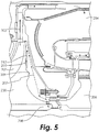
- the rotor 200 in the exemplary embodiment comprises an impeller having a plurality of impeller blades 202 on a forward surface thereof which direct gases in the gas path of the engine along a path 203 to a combustor section 204 where the gases are combusted with fuel.
- the exhaust gases from the combustor 204 flow to a turbine section 206.
- Some of the gases flowing past the impeller 200 follow a path 207 aft of the impeller 200 and enter a secondary air system 208 within the engine that is designed to prevent hot gas ingestion and to cool parts of the engine.
- a boundary layer can develop on the aft side 210.
- the centrifugal forces resulting from shear between the aft side 210 and the gases aft of the impeller 200 can cause a boundary layer radial outflow 212 that interacts with the gases following the path 207. It will be appreciated that preventing or reducing this interaction by breaking down the boundary layer 212 will improve performance of the secondary air system 208.
- a known balancing rim 209 is illustrated on the impeller 200.
- the impeller 200 may be modified to include a rim 220 on the aft side 212.
- the rim 220 may be provided in addition to the balancing rim 209, or the rim 220 may be used as a balancing rim (from which material may be removed during an operation to rotationally balance the rotor) and the balancing rim 209 may be eliminated. It will be appreciated that in some embodiments, the rim 220 may be formed in two or more segments as discussed above with respect to the asymmetric rim 106.
- the rim 220 includes an outward sloping surface 222 tilted in the aft direction, i.e., an axial thickness of the rim 220 at its radially outer edge is greater than an axial thickness of the rim 220 at its radially inner edge.
- the sloping surface 222 moves the boundary layer away from a main surface 223 of the impeller 200 and helps to prevent re-attachment of the boundary layer with the main surface 223 past the balancing rim 222 radially outer edge.
- the radially inner surface of the balancing rim 222 may comprise a sloping surface 224 tilted radially inward, i.e., the sloping surface 224 is disposed at a larger radius at its forward edge than at its aft edge.
- the sloping surface 224 will redirect the entrained mass flow inside the boundary layer 212 radially inward along the path 226 and further helps to prevent re-attachment of the boundary layer past the balancing rim 222 radially outer edge.
- sloping surface 228 sloping in the aft direction may be provided, i.e., the radially inner edge of sloping surface 228 is forward of the radially outer edge of sloping surface 228.
- the sloping surface 228 forms an angle between approximately 1 degree and approximately five degrees with a plane perpendicular to the axis of rotation of the impeller 200. The sloping surface 228 further helps to prevent re-attachment of the boundary layer past the balancing rim 222 radially outer edge.
Claims (11)
- Rotor (100, 200) d'un compresseur radial définissant un axe de rotation, le rotor comprenant :un côté avant (102) ayant une pluralité de pales de rotor (103, 105) s'étendant à partir de celui-ci ; etun côté arrière (210) situé fluidiquement en aval du côté avant ;caractérisé en ce que le rotor comprend en outre un rebord asymétrique (220) disposé sur le côté arrière (210) pour réduire l'amplitude de vibration.
- Rotor selon la revendication 1, dans lequel le rotor (200) comprend une roue à l'intérieur d'un moteur à turbine à gaz.
- Rotor selon une quelconque revendication précédente, dans lequel le rebord asymétrique (220) comprend un rebord d'équilibrage.
- Rotor selon une quelconque revendication précédente, dans lequel le rebord asymétrique (220) comprend :un premier segment comportant un premier bord radialement externe disposé au niveau d'un premier rayon (R1), un premier bord radialement interne disposé au niveau d'un deuxième rayon (R2) ; etun deuxième segment comportant un deuxième bord radialement externe disposé au niveau d'un troisième rayon (R3), un deuxième bord radialement interne disposé au niveau d'un quatrième rayon (R4) ;dans lequel le premier rayon (R1) est différent du troisième rayon (R3) et le deuxième rayon (R2) est différent du quatrième rayon (R4).
- Rotor selon la revendication 4, comprenant en outre :
un troisième segment comportant un troisième bord radialement externe disposé au niveau d'un cinquième rayon et un troisième bord radialement interne disposé au niveau d'un sixième rayon. - Rotor selon la revendication 4 ou 5, dans lequel :le premier segment comporte une première épaisseur au niveau du premier bord radialement externe qui est supérieure à une deuxième épaisseur au niveau du premier bord radialement interne ; etle deuxième segment comporte une troisième épaisseur au niveau du deuxième bord radialement externe qui est supérieure à une quatrième épaisseur au niveau du premier bord radialement interne.
- Rotor selon la revendication 4, 5 ou 6, dans lequel les premier et deuxième segments comportent chacun une surface comportant un bord avant et un bord arrière, dans lequel le bord avant est disposé à un rayon plus grand que le bord arrière.
- Rotor selon une quelconque revendication précédente, dans lequel le rebord asymétrique (200) comprend :un premier segment ayant une première épaisseur et un premier centre de gravité disposé au niveau d'un premier rayon ;un deuxième segment ayant une deuxième épaisseur et un second centre de gravité disposé au niveau du premier rayon ;dans lequel la première épaisseur est différente de la deuxième épaisseur.
- Rotor selon une quelconque revendication précédente, dans lequel une surface (228) du côté arrière (210) radialement vers l'extérieur du rebord asymétrique (220) est disposée selon un angle par rapport à un plan perpendiculaire à l'axe de rotation de sorte qu'un bord radialement interne de la surface (228) est en avant d'un bord radialement externe de la surface (228).
- Rotor selon la revendication 9, dans lequel l'angle comprend un angle compris entre environ un degré et environ cinq degrés.
- Ensemble pour un moteur à turbine à gaz (20), l'ensemble comprenant :un composant de moteur ; etun rotor (100, 200) d'un compresseur radial selon une quelconque revendication précédente disposé dans le composant ;dans lequel le composant comprend l'une parmi une section de compresseur (24), une section de combustion (26), une section de turbine (28) et une section d'échappement.
Applications Claiming Priority (1)
| Application Number | Priority Date | Filing Date | Title |
|---|---|---|---|
| US201461990468P | 2014-05-08 | 2014-05-08 |
Publications (2)
| Publication Number | Publication Date |
|---|---|
| EP2960432A1 EP2960432A1 (fr) | 2015-12-30 |
| EP2960432B1 true EP2960432B1 (fr) | 2021-10-20 |
Family
ID=53015734
Family Applications (1)
| Application Number | Title | Priority Date | Filing Date |
|---|---|---|---|
| EP15166116.2A Active EP2960432B1 (fr) | 2014-05-08 | 2015-05-01 | Rotor et moteur à turbine à gaz comprenant un rotor |
Country Status (1)
| Country | Link |
|---|---|
| EP (1) | EP2960432B1 (fr) |
Families Citing this family (4)
| Publication number | Priority date | Publication date | Assignee | Title |
|---|---|---|---|---|
| US10865646B2 (en) | 2017-05-04 | 2020-12-15 | Rolls-Royce Corporation | Turbine assembly with auxiliary wheel |
| US10774678B2 (en) | 2017-05-04 | 2020-09-15 | Rolls-Royce Corporation | Turbine assembly with auxiliary wheel |
| CA2998215A1 (fr) * | 2017-05-04 | 2018-11-04 | Rolls-Royce Corporation | Assemblage de turbine a roue auxiliaire |
| US10968744B2 (en) | 2017-05-04 | 2021-04-06 | Rolls-Royce Corporation | Turbine rotor assembly having a retaining collar for a bayonet mount |
Family Cites Families (6)
| Publication number | Priority date | Publication date | Assignee | Title |
|---|---|---|---|---|
| US4294135A (en) * | 1979-01-12 | 1981-10-13 | The United States Of America As Represented By The Secretary Of The Navy | Turbomachine balance correction system |
| DE3026558C2 (de) * | 1980-07-12 | 1982-09-09 | Audi Nsu Auto Union Ag, 7107 Neckarsulm | Turbomaschine, insbesondere Abgasturbolader für Brennkraftmaschinen |
| US4926710A (en) * | 1987-09-08 | 1990-05-22 | United Technologies Corporation | Method of balancing bladed gas turbine engine rotor |
| FR2716931B1 (fr) * | 1994-03-03 | 1996-04-05 | Snecma | Système d'équilibrage et d'amortissement d'un dique de turbomachine. |
| US6588298B2 (en) * | 2001-03-23 | 2003-07-08 | United Technologies Corporation | Rotor balancing system for turbomachinery |
| US7296976B2 (en) * | 2004-10-20 | 2007-11-20 | Rolls-Royce Corporation | Dual counterweight balancing system |
-
2015
- 2015-05-01 EP EP15166116.2A patent/EP2960432B1/fr active Active
Non-Patent Citations (1)
| Title |
|---|
| None * |
Also Published As
| Publication number | Publication date |
|---|---|
| EP2960432A1 (fr) | 2015-12-30 |
Similar Documents
| Publication | Publication Date | Title |
|---|---|---|
| US10808543B2 (en) | Rotors with modulus mistuned airfoils | |
| EP2960432B1 (fr) | Rotor et moteur à turbine à gaz comprenant un rotor | |
| US10415391B2 (en) | Rotor and gas turbine engine including a rotor | |
| JP2011033020A (ja) | タービンエンジン用のロータブレード | |
| US9169849B2 (en) | Gas turbine engine compressor stator seal | |
| JP2015525852A (ja) | 選択的に孔が揃えられた回転タービン部品 | |
| US10641112B2 (en) | Bladed disk | |
| US10968760B2 (en) | Gas turbine engine component for acoustic attenuation | |
| US10066502B2 (en) | Bladed rotor disk including anti-vibratory feature | |
| US9938854B2 (en) | Gas turbine engine airfoil curvature | |
| US10677266B1 (en) | Gas turbine engine airfoil frequency design | |
| US10788049B1 (en) | Gas turbine engine airfoil frequency design | |
| US10533581B2 (en) | Stator with support structure feature for tuned airfoil | |
| US11293294B2 (en) | Speed-controlled conditioning valve for high pressure compressor | |
| US11346282B2 (en) | Gas turbine engine component for acoustic attenuation | |
| US11698002B1 (en) | Gas turbine engine airfoil frequency design | |
| US11767763B1 (en) | Gas turbine engine airfoil frequency design | |
| US10815826B1 (en) | Gas turbine engine airfoil frequency design | |
| US10760447B1 (en) | Gas turbine engine airfoil frequency design | |
| US10774651B1 (en) | Gas turbine engine airfoil frequency design | |
| US10683761B1 (en) | Gas turbine engine airfoil frequency design | |
| US10865809B1 (en) | Gas turbine engine airfoil frequency design | |
| CN108779677B (zh) | 用于燃气轮机的包含一个或多个封装空洞的翼型 | |
| US11236616B1 (en) | Gas turbine engine airfoil frequency design | |
| US11231050B1 (en) | Gas turbine engine airfoil frequency design |
Legal Events
| Date | Code | Title | Description |
|---|---|---|---|
| PUAI | Public reference made under article 153(3) epc to a published international application that has entered the european phase |
Free format text: ORIGINAL CODE: 0009012 |
|
| AK | Designated contracting states |
Kind code of ref document: A1 Designated state(s): AL AT BE BG CH CY CZ DE DK EE ES FI FR GB GR HR HU IE IS IT LI LT LU LV MC MK MT NL NO PL PT RO RS SE SI SK SM TR |
|
| AX | Request for extension of the european patent |
Extension state: BA ME |
|
| 17P | Request for examination filed |
Effective date: 20160630 |
|
| RBV | Designated contracting states (corrected) |
Designated state(s): AL AT BE BG CH CY CZ DE DK EE ES FI FR GB GR HR HU IE IS IT LI LT LU LV MC MK MT NL NO PL PT RO RS SE SI SK SM TR |
|
| RAP1 | Party data changed (applicant data changed or rights of an application transferred) |
Owner name: UNITED TECHNOLOGIES CORPORATION |
|
| STAA | Information on the status of an ep patent application or granted ep patent |
Free format text: STATUS: EXAMINATION IS IN PROGRESS |
|
| 17Q | First examination report despatched |
Effective date: 20180731 |
|
| GRAP | Despatch of communication of intention to grant a patent |
Free format text: ORIGINAL CODE: EPIDOSNIGR1 |
|
| STAA | Information on the status of an ep patent application or granted ep patent |
Free format text: STATUS: GRANT OF PATENT IS INTENDED |
|
| INTG | Intention to grant announced |
Effective date: 20201113 |
|
| GRAJ | Information related to disapproval of communication of intention to grant by the applicant or resumption of examination proceedings by the epo deleted |
Free format text: ORIGINAL CODE: EPIDOSDIGR1 |
|
| RAP1 | Party data changed (applicant data changed or rights of an application transferred) |
Owner name: RAYTHEON TECHNOLOGIES CORPORATION |
|
| STAA | Information on the status of an ep patent application or granted ep patent |
Free format text: STATUS: EXAMINATION IS IN PROGRESS |
|
| GRAP | Despatch of communication of intention to grant a patent |
Free format text: ORIGINAL CODE: EPIDOSNIGR1 |
|
| INTC | Intention to grant announced (deleted) | ||
| STAA | Information on the status of an ep patent application or granted ep patent |
Free format text: STATUS: GRANT OF PATENT IS INTENDED |
|
| INTG | Intention to grant announced |
Effective date: 20210429 |
|
| GRAS | Grant fee paid |
Free format text: ORIGINAL CODE: EPIDOSNIGR3 |
|
| GRAA | (expected) grant |
Free format text: ORIGINAL CODE: 0009210 |
|
| STAA | Information on the status of an ep patent application or granted ep patent |
Free format text: STATUS: THE PATENT HAS BEEN GRANTED |
|
| AK | Designated contracting states |
Kind code of ref document: B1 Designated state(s): AL AT BE BG CH CY CZ DE DK EE ES FI FR GB GR HR HU IE IS IT LI LT LU LV MC MK MT NL NO PL PT RO RS SE SI SK SM TR |
|
| REG | Reference to a national code |
Ref country code: GB Ref legal event code: FG4D |
|
| REG | Reference to a national code |
Ref country code: CH Ref legal event code: EP |
|
| REG | Reference to a national code |
Ref country code: DE Ref legal event code: R096 Ref document number: 602015074210 Country of ref document: DE |
|
| REG | Reference to a national code |
Ref country code: IE Ref legal event code: FG4D |
|
| REG | Reference to a national code |
Ref country code: AT Ref legal event code: REF Ref document number: 1440117 Country of ref document: AT Kind code of ref document: T Effective date: 20211115 |
|
| REG | Reference to a national code |
Ref country code: LT Ref legal event code: MG9D |
|
| REG | Reference to a national code |
Ref country code: NL Ref legal event code: MP Effective date: 20211020 |
|
| REG | Reference to a national code |
Ref country code: AT Ref legal event code: MK05 Ref document number: 1440117 Country of ref document: AT Kind code of ref document: T Effective date: 20211020 |
|
| PG25 | Lapsed in a contracting state [announced via postgrant information from national office to epo] |
Ref country code: RS Free format text: LAPSE BECAUSE OF FAILURE TO SUBMIT A TRANSLATION OF THE DESCRIPTION OR TO PAY THE FEE WITHIN THE PRESCRIBED TIME-LIMIT Effective date: 20211020 Ref country code: LT Free format text: LAPSE BECAUSE OF FAILURE TO SUBMIT A TRANSLATION OF THE DESCRIPTION OR TO PAY THE FEE WITHIN THE PRESCRIBED TIME-LIMIT Effective date: 20211020 Ref country code: FI Free format text: LAPSE BECAUSE OF FAILURE TO SUBMIT A TRANSLATION OF THE DESCRIPTION OR TO PAY THE FEE WITHIN THE PRESCRIBED TIME-LIMIT Effective date: 20211020 Ref country code: BG Free format text: LAPSE BECAUSE OF FAILURE TO SUBMIT A TRANSLATION OF THE DESCRIPTION OR TO PAY THE FEE WITHIN THE PRESCRIBED TIME-LIMIT Effective date: 20220120 Ref country code: AT Free format text: LAPSE BECAUSE OF FAILURE TO SUBMIT A TRANSLATION OF THE DESCRIPTION OR TO PAY THE FEE WITHIN THE PRESCRIBED TIME-LIMIT Effective date: 20211020 |
|
| PG25 | Lapsed in a contracting state [announced via postgrant information from national office to epo] |
Ref country code: IS Free format text: LAPSE BECAUSE OF FAILURE TO SUBMIT A TRANSLATION OF THE DESCRIPTION OR TO PAY THE FEE WITHIN THE PRESCRIBED TIME-LIMIT Effective date: 20220220 Ref country code: SE Free format text: LAPSE BECAUSE OF FAILURE TO SUBMIT A TRANSLATION OF THE DESCRIPTION OR TO PAY THE FEE WITHIN THE PRESCRIBED TIME-LIMIT Effective date: 20211020 Ref country code: PT Free format text: LAPSE BECAUSE OF FAILURE TO SUBMIT A TRANSLATION OF THE DESCRIPTION OR TO PAY THE FEE WITHIN THE PRESCRIBED TIME-LIMIT Effective date: 20220221 Ref country code: PL Free format text: LAPSE BECAUSE OF FAILURE TO SUBMIT A TRANSLATION OF THE DESCRIPTION OR TO PAY THE FEE WITHIN THE PRESCRIBED TIME-LIMIT Effective date: 20211020 Ref country code: NO Free format text: LAPSE BECAUSE OF FAILURE TO SUBMIT A TRANSLATION OF THE DESCRIPTION OR TO PAY THE FEE WITHIN THE PRESCRIBED TIME-LIMIT Effective date: 20220120 Ref country code: NL Free format text: LAPSE BECAUSE OF FAILURE TO SUBMIT A TRANSLATION OF THE DESCRIPTION OR TO PAY THE FEE WITHIN THE PRESCRIBED TIME-LIMIT Effective date: 20211020 Ref country code: LV Free format text: LAPSE BECAUSE OF FAILURE TO SUBMIT A TRANSLATION OF THE DESCRIPTION OR TO PAY THE FEE WITHIN THE PRESCRIBED TIME-LIMIT Effective date: 20211020 Ref country code: HR Free format text: LAPSE BECAUSE OF FAILURE TO SUBMIT A TRANSLATION OF THE DESCRIPTION OR TO PAY THE FEE WITHIN THE PRESCRIBED TIME-LIMIT Effective date: 20211020 Ref country code: GR Free format text: LAPSE BECAUSE OF FAILURE TO SUBMIT A TRANSLATION OF THE DESCRIPTION OR TO PAY THE FEE WITHIN THE PRESCRIBED TIME-LIMIT Effective date: 20220121 Ref country code: ES Free format text: LAPSE BECAUSE OF FAILURE TO SUBMIT A TRANSLATION OF THE DESCRIPTION OR TO PAY THE FEE WITHIN THE PRESCRIBED TIME-LIMIT Effective date: 20211020 |
|
| REG | Reference to a national code |
Ref country code: DE Ref legal event code: R097 Ref document number: 602015074210 Country of ref document: DE |
|
| PG25 | Lapsed in a contracting state [announced via postgrant information from national office to epo] |
Ref country code: SM Free format text: LAPSE BECAUSE OF FAILURE TO SUBMIT A TRANSLATION OF THE DESCRIPTION OR TO PAY THE FEE WITHIN THE PRESCRIBED TIME-LIMIT Effective date: 20211020 Ref country code: SK Free format text: LAPSE BECAUSE OF FAILURE TO SUBMIT A TRANSLATION OF THE DESCRIPTION OR TO PAY THE FEE WITHIN THE PRESCRIBED TIME-LIMIT Effective date: 20211020 Ref country code: RO Free format text: LAPSE BECAUSE OF FAILURE TO SUBMIT A TRANSLATION OF THE DESCRIPTION OR TO PAY THE FEE WITHIN THE PRESCRIBED TIME-LIMIT Effective date: 20211020 Ref country code: EE Free format text: LAPSE BECAUSE OF FAILURE TO SUBMIT A TRANSLATION OF THE DESCRIPTION OR TO PAY THE FEE WITHIN THE PRESCRIBED TIME-LIMIT Effective date: 20211020 Ref country code: DK Free format text: LAPSE BECAUSE OF FAILURE TO SUBMIT A TRANSLATION OF THE DESCRIPTION OR TO PAY THE FEE WITHIN THE PRESCRIBED TIME-LIMIT Effective date: 20211020 Ref country code: CZ Free format text: LAPSE BECAUSE OF FAILURE TO SUBMIT A TRANSLATION OF THE DESCRIPTION OR TO PAY THE FEE WITHIN THE PRESCRIBED TIME-LIMIT Effective date: 20211020 |
|
| PLBE | No opposition filed within time limit |
Free format text: ORIGINAL CODE: 0009261 |
|
| STAA | Information on the status of an ep patent application or granted ep patent |
Free format text: STATUS: NO OPPOSITION FILED WITHIN TIME LIMIT |
|
| 26N | No opposition filed |
Effective date: 20220721 |
|
| PG25 | Lapsed in a contracting state [announced via postgrant information from national office to epo] |
Ref country code: AL Free format text: LAPSE BECAUSE OF FAILURE TO SUBMIT A TRANSLATION OF THE DESCRIPTION OR TO PAY THE FEE WITHIN THE PRESCRIBED TIME-LIMIT Effective date: 20211020 |
|
| PG25 | Lapsed in a contracting state [announced via postgrant information from national office to epo] |
Ref country code: SI Free format text: LAPSE BECAUSE OF FAILURE TO SUBMIT A TRANSLATION OF THE DESCRIPTION OR TO PAY THE FEE WITHIN THE PRESCRIBED TIME-LIMIT Effective date: 20211020 |
|
| REG | Reference to a national code |
Ref country code: CH Ref legal event code: PL |
|
| REG | Reference to a national code |
Ref country code: BE Ref legal event code: MM Effective date: 20220531 |
|
| PG25 | Lapsed in a contracting state [announced via postgrant information from national office to epo] |
Ref country code: MC Free format text: LAPSE BECAUSE OF FAILURE TO SUBMIT A TRANSLATION OF THE DESCRIPTION OR TO PAY THE FEE WITHIN THE PRESCRIBED TIME-LIMIT Effective date: 20211020 Ref country code: LU Free format text: LAPSE BECAUSE OF NON-PAYMENT OF DUE FEES Effective date: 20220501 Ref country code: LI Free format text: LAPSE BECAUSE OF NON-PAYMENT OF DUE FEES Effective date: 20220531 Ref country code: CH Free format text: LAPSE BECAUSE OF NON-PAYMENT OF DUE FEES Effective date: 20220531 |
|
| PG25 | Lapsed in a contracting state [announced via postgrant information from national office to epo] |
Ref country code: IE Free format text: LAPSE BECAUSE OF NON-PAYMENT OF DUE FEES Effective date: 20220501 |
|
| PG25 | Lapsed in a contracting state [announced via postgrant information from national office to epo] |
Ref country code: IT Free format text: LAPSE BECAUSE OF FAILURE TO SUBMIT A TRANSLATION OF THE DESCRIPTION OR TO PAY THE FEE WITHIN THE PRESCRIBED TIME-LIMIT Effective date: 20211020 Ref country code: BE Free format text: LAPSE BECAUSE OF NON-PAYMENT OF DUE FEES Effective date: 20220531 |
|
| P01 | Opt-out of the competence of the unified patent court (upc) registered |
Effective date: 20230520 |
|
| PGFP | Annual fee paid to national office [announced via postgrant information from national office to epo] |
Ref country code: FR Payment date: 20230420 Year of fee payment: 9 Ref country code: DE Payment date: 20230419 Year of fee payment: 9 |
|
| PGFP | Annual fee paid to national office [announced via postgrant information from national office to epo] |
Ref country code: GB Payment date: 20230420 Year of fee payment: 9 |
|
| PG25 | Lapsed in a contracting state [announced via postgrant information from national office to epo] |
Ref country code: HU Free format text: LAPSE BECAUSE OF FAILURE TO SUBMIT A TRANSLATION OF THE DESCRIPTION OR TO PAY THE FEE WITHIN THE PRESCRIBED TIME-LIMIT; INVALID AB INITIO Effective date: 20150501 |
|
| PG25 | Lapsed in a contracting state [announced via postgrant information from national office to epo] |
Ref country code: MK Free format text: LAPSE BECAUSE OF FAILURE TO SUBMIT A TRANSLATION OF THE DESCRIPTION OR TO PAY THE FEE WITHIN THE PRESCRIBED TIME-LIMIT Effective date: 20211020 Ref country code: CY Free format text: LAPSE BECAUSE OF FAILURE TO SUBMIT A TRANSLATION OF THE DESCRIPTION OR TO PAY THE FEE WITHIN THE PRESCRIBED TIME-LIMIT Effective date: 20211020 |