EP2960378A1 - Pipe supporting device for construction machine - Google Patents
Pipe supporting device for construction machine Download PDFInfo
- Publication number
- EP2960378A1 EP2960378A1 EP15172639.5A EP15172639A EP2960378A1 EP 2960378 A1 EP2960378 A1 EP 2960378A1 EP 15172639 A EP15172639 A EP 15172639A EP 2960378 A1 EP2960378 A1 EP 2960378A1
- Authority
- EP
- European Patent Office
- Prior art keywords
- oblique
- standing
- pair
- standing surfaces
- supporting device
- Prior art date
- Legal status (The legal status is an assumption and is not a legal conclusion. Google has not performed a legal analysis and makes no representation as to the accuracy of the status listed.)
- Granted
Links
- 238000010276 construction Methods 0.000 title claims description 7
- 238000003466 welding Methods 0.000 claims abstract description 28
- 230000001154 acute effect Effects 0.000 claims abstract description 14
- 230000002093 peripheral effect Effects 0.000 claims abstract description 12
- 238000011282 treatment Methods 0.000 abstract description 29
- 239000011324 bead Substances 0.000 description 14
- 238000010586 diagram Methods 0.000 description 3
- 238000012986 modification Methods 0.000 description 3
- 230000004048 modification Effects 0.000 description 3
- 238000009412 basement excavation Methods 0.000 description 2
- 238000005452 bending Methods 0.000 description 2
- 239000000872 buffer Substances 0.000 description 2
- 230000000694 effects Effects 0.000 description 2
- 230000002349 favourable effect Effects 0.000 description 2
- 238000003780 insertion Methods 0.000 description 2
- 230000037431 insertion Effects 0.000 description 2
- 238000000034 method Methods 0.000 description 2
- 239000002184 metal Substances 0.000 description 1
Images




Classifications
-
- F—MECHANICAL ENGINEERING; LIGHTING; HEATING; WEAPONS; BLASTING
- F16—ENGINEERING ELEMENTS AND UNITS; GENERAL MEASURES FOR PRODUCING AND MAINTAINING EFFECTIVE FUNCTIONING OF MACHINES OR INSTALLATIONS; THERMAL INSULATION IN GENERAL
- F16B—DEVICES FOR FASTENING OR SECURING CONSTRUCTIONAL ELEMENTS OR MACHINE PARTS TOGETHER, e.g. NAILS, BOLTS, CIRCLIPS, CLAMPS, CLIPS OR WEDGES; JOINTS OR JOINTING
- F16B5/00—Joining sheets or plates, e.g. panels, to one another or to strips or bars parallel to them
- F16B5/08—Joining sheets or plates, e.g. panels, to one another or to strips or bars parallel to them by means of welds or the like
-
- E—FIXED CONSTRUCTIONS
- E02—HYDRAULIC ENGINEERING; FOUNDATIONS; SOIL SHIFTING
- E02F—DREDGING; SOIL-SHIFTING
- E02F9/00—Component parts of dredgers or soil-shifting machines, not restricted to one of the kinds covered by groups E02F3/00 - E02F7/00
-
- E—FIXED CONSTRUCTIONS
- E02—HYDRAULIC ENGINEERING; FOUNDATIONS; SOIL SHIFTING
- E02F—DREDGING; SOIL-SHIFTING
- E02F9/00—Component parts of dredgers or soil-shifting machines, not restricted to one of the kinds covered by groups E02F3/00 - E02F7/00
- E02F9/20—Drives; Control devices
- E02F9/22—Hydraulic or pneumatic drives
- E02F9/2264—Arrangements or adaptations of elements for hydraulic drives
- E02F9/2275—Hoses and supports therefor and protection therefor
-
- F—MECHANICAL ENGINEERING; LIGHTING; HEATING; WEAPONS; BLASTING
- F16—ENGINEERING ELEMENTS AND UNITS; GENERAL MEASURES FOR PRODUCING AND MAINTAINING EFFECTIVE FUNCTIONING OF MACHINES OR INSTALLATIONS; THERMAL INSULATION IN GENERAL
- F16L—PIPES; JOINTS OR FITTINGS FOR PIPES; SUPPORTS FOR PIPES, CABLES OR PROTECTIVE TUBING; MEANS FOR THERMAL INSULATION IN GENERAL
- F16L3/00—Supports for pipes, cables or protective tubing, e.g. hangers, holders, clamps, cleats, clips, brackets
- F16L3/22—Supports for pipes, cables or protective tubing, e.g. hangers, holders, clamps, cleats, clips, brackets specially adapted for supporting a number of parallel pipes at intervals
- F16L3/237—Supports for pipes, cables or protective tubing, e.g. hangers, holders, clamps, cleats, clips, brackets specially adapted for supporting a number of parallel pipes at intervals for two pipes
Definitions
- the present invention relates to a pipe supporting device for supporting a hydraulic pipe provided in a construction machine.
- construction machines including a machine body, an attachment mounted on the machine body pivotally around a horizontal axis, and a pipe supporting device for supporting a hydraulic pipe provided on the attachment.
- Patent Literature 1 a pipe supporting device disclosed in Japanese Patent Publication No. 4704888 (hereinafter referred to as "Patent Literature 1”) includes a plate connected with an upper surface of an arm of a hydraulic excavator by welding, and a pipe clamp provided on the plate.
- FIGS. 11 and 12 illustrate a state of the arm and the plate connected with each other by welding as disclosed in Patent Literature 1.
- the plate 21 is connected with an upper surface of a top plate 20 of the arm by fillet welding. Specifically, the plate 21 is connected to the top plate 20 by means of a weld bead 22 provided along mutually adjacent side surfaces 21a and 21b, as shown in FIG. 12 .
- the side surfaces 21a and 21b of the plate 21 join each other at an angle 21c greater than 90 degrees, i.e. at an obtuse angle.
- a stress occurs in the top plate 20 of the arm in a direction along the length of the arm (hereinafter, the direction of the stress will be referred to as a first stress direction D7).
- another stress may occur in the top plate of the arm in a second stress direction D8 perpendicularly intersecting the first stress direction D7 due to a reaction force received from a cylinder for driving a bucket when the arm is operated.
- the side surface 21a of the plate 21 extends in the first stress direction D7, i.e. in the direction perpendicularly intersecting the second stress direction D8. Therefore, the strength of the weld formed at the side surface 21a is liable to be insufficient against the stress occurring in the second stress direction D8.
- the side surface 21b of the plate 21 extends obliquely to both of the stress directions D7 and D8. This makes, among stress components acting in the stress directions D7 and D8, the stress component acting in a direction perpendicularly intersecting the side surface 21b smaller. Therefore, the strength of the weld formed at the side surface 21b is greater than that at the other part.
- the bead 22 is ground from a toe of weld of the bead 22 (perpendicular portion 22a and the corner portion 22c) over a predetermined region level so that the cross-sectional area of the bead 22 gradually increases in the second stress direction D8.
- the grinder G is caused to reciprocate in a grinding direction D5 parallel to the second stress direction D8 while moving in a movement direction D6 extending along the perpendicular portion 22a, to thereby grind the perpendicular portion 22a and the corner portion 22c.
- the grinding using the grinder G is performed from the perpendicular portion 22a to a terminating end 23c defined by a boundary between the corner portion 22c and the oblique portion 22b.
- the present invention has an object of providing a pipe supporting device which allows a finishing treatment to be easily performed on a terminating end of grinding performed on a weld formed on an attachment.
- the present invention provides a pipe supporting device for use in a construction machine including a machine body, an attachment mounted on the machine body pivotably around a horizontal axis, and a hydraulic pipe extending along a length of the attachment, the pipe supporting device comprising: a support portion for supporting the hydraulic pipe along an axis of the hydraulic pipe extending along the length of the attachment; and a weld portion joining the support portion and to be connected with an outer surface of the attachment by fillet welding, wherein the weld portion has a plurality of peripheral surfaces standing on the outer surface of the attachment for the fillet welding, the plurality of peripheral surfaces including: a pair of opposite perpendicular standing surfaces extending in a direction substantially perpendicularly intersecting the axis of the hydraulic pipe; and a pair of oblique standing surfaces extending from respective leading ends of the pair of opposite perpendicular standing surfaces to join each other, each of the oblique standing surfaces extending in a direction oblique to the axis of the hydraulic
- a hydraulic excavator 1 which exemplifies a construction machine according to an embodiment of the present invention, includes a lower travelling body 2 having a pair of crawlers 2a, an upper slewing body 3 pivotally mounted on the lower travelling body 2, a working machine 4 movably mounted on the upper slewing body 3 and a pair of pipe supporting devices 12 (see FIG. 2 ) supporting the hydraulic pipes 11 (see FIG. 2 ) provided in the working machine 4.
- the lower travelling body 2 and the upper slewing body 3 constitute a machine body pivotally supporting a boom 5 described later.
- the working machine 4 includes the boom 5 (attachment) mounted to the upper slewing body 3 pivotally around a horizontal axis J1, an arm 6 mounted to a distal end of the boom 5 pivotally around a horizontal axis, and a bucket 7 mounted to a distal end of the arm 6 pivotally around a horizontal axis.
- the working machine 4 includes a boom cylinder 8 for driving the boom 5 to move upward and downward with respect to the upper slewing body 3, an arm cylinder 9 for driving the arm 6 to pivot with respect to the boom 5, and a bucket cylinder 10 for driving the bucket 7 to pivot with respect to the arm 6.
- the boom 5 is in the form of a cylinder having a closed section on a plane perpendicularly intersecting a length D1 of the boom 5.
- the boom 5 includes a pair of side plates 5a (only one of which is shown in FIG. 2 ) facing each other in the direction perpendicularly intersecting the length D1, a top plate 5b connecting respective upper ends of the side plates 5a, and a bottom plate 5c connecting respective lower ends of the side plates 5a.
- the length D1 is on a vertically center line of the boom 5 connecting centers between the top plate 5b and the bottom plate 5c.
- the boom 5 includes a boss 5e to which a distal end of the boom cylinder 8 attached, and a pair of brackets 5d to which a base end of the arm cylinder 9 attached.
- the boss 5e passes through the opposite side plates 5a, and is connected with the opposite side plates 5a by welding.
- the brackets 5d stand on the top plate 5b and extend along the length D1, the brackets 5d facing each other in the direction perpendicularly intersecting the length D1 (in the direction of the opposite side plates 5a facing each other).
- a connecting pin which connects the arm cylinder 9 and the brackets 5d receives a force in the direction along the length D1, the force being a reaction force to a pulling movement of the arm 6 (extension of the arm cylinder 9).
- respective lower ends of the brackets 5d are secured on the top plate 5b. Therefore, when the connecting pin receives the force, the brackets 5d deform (incline) in such a way that respective upper ends of the brackets 5d move away from each other.
- the portion of the top plate 5b that is between the opposite brackets 5d (a widthwise middle portion of the top plate 5b) bulges upward so that a bending deformation is occur on the top plate 5b.
- a tensile stress occurs in the top plate 5b in a second stress direction D4 (see FIG. 5 ) perpendicularly intersecting the length D1.
- the hydraulic pipes 11 are disposed on the top plate 5b of the boom 5 and along the length D1, and are respectively connected to the arm cylinder 9 and the bucket cylinder 10.
- the pair of pipe supporting devices 12 is disposed in widthwise symmetry as shown in FIG. 2 .
- the pipe supporting device 12 on the left side will be described.
- FIG. 3 is a perspective view showing an overall configuration of the pipe supporting device 12.
- FIG. 4 is a perspective view of the pipe supporting device shown in FIG. 3 with a support portion 15 thereof detached.
- the pipe supporting device 12 includes the support portion 15 for supporting two hydraulic pipes 11 along respective axes D2 of the two hydraulic pipes 11, the axes extending along the length D1 of the boom 5, a weld portion 13 connected with an upper surface (outer surface) of the top plate 5b of the boom 5 by fillet welding, and a connecting stand 14 connecting the support portion 15 and the weld portion 13.
- the support portion 15 includes a pair of upper and lower clamping plates 15a, buffers 15b respectively provided between the clamping plates 15a and each of the hydraulic pipes 11, and two bolts 15c securing the clamping plates 15a to the connecting stand 14.
- the pair of clamping plates 15a includes a pair of opposite upper and lower clamping portions (not denoted by a reference numeral) which define spaces respectively corresponding to the cross section of each of the hydraulic pipes 11, and insertion holes (not shown) formed between the clamping portions to allow the bolts 15c to pass therethrough.
- the bolts 15c are inserted in the insertion holes from above and screwed into screw holes 14a (see FIG. 4 ) formed in the connecting stand 14 to thereby connect the clamping plates 15a to the connecting stand 14 with the hydraulic pipes 11 being sandwiched between the opposite clamping portions of the clamping plates 15a.
- Each of the buffers 15b is provided between the inner surfaces of the clamping portions of the clamping plates 15a and the outer surface of the corresponding hydraulic pipe 11, to prevent the hydraulic pipes 11 from being damaged by the clamping portions.
- the weld portion 13 is in the form of a metal plate and connected, by fillet welding, with the top plate 5b by means of a weld bead B formed between peripheral surfaces of the weld portion 13 and the upper surface of the top plate 5b of the boom 5.
- the peripheral surfaces of the weld portion 13 stand on the top plate 5b and include a pair of opposite perpendicular standing surfaces 13a and 13b extending in a direction substantially perpendicularly intersecting the axes D2 of the hydraulic pipe 11, and a pair of oblique standing surfaces 13c and 13d extending from respective leading ends of the pair of opposite perpendicular standing surfaces 13a and 13b to join each other, each of the oblique surfaces 13c and 13d extending in a direction oblique to the axes D2 of the hydraulic pipe 11.
- the respective leading ends of the opposite perpendicular standing surfaces 13a and 13b, which join the oblique standing surfaces 13c and 13d, respectively, are located at positions away from each of the axes D2 of the hydraulic pipes 11 the same distance in a direction (i.e. the second stress direction D4) perpendicularly intersecting the axes D2.
- the oblique standing surface 13c joins the perpendicular standing surface 13a at an acute angle ⁇ , and the oblique standing surface 13d also joins the perpendicular standing surface 13b at the acute angle ⁇ .
- the angle ⁇ is set at about 65 degrees.
- the oblique standing surfaces 13c and 13d are flat and join each other to define an angle.
- the oblique standing surfaces 13c and 13d are symmetrically disposed with respect to a straight line L1 through which a plane passing the middle between the pair of opposite perpendicular standing surfaces 13a and 13b and perpendicularly intersecting the axes D2 of the hydraulic pipes 11 passes.
- the oblique standing surfaces 13c and 13d have the same length and are disposed at the same angle.
- the above-described pipe supporting device 12 is connected to the boom 5 by fillet welding, for example, as described below.
- the weld portion 13 is disposed on the top plate 5b of the boom 5 in such a way that the opposite perpendicular standing surfaces 13a and 13b of the weld portion 13 perpendicularly intersect the first stress direction D3 on the top plate 5b. This allows the oblique standing surfaces 13c and 13d to be disposed obliquely to the first stress direction D3 and the second stress direction D4.
- one end of the weld portion 13 along the second stress direction D4 is located at an outer position than the widthwise middle of the top plate 5b in the second stress direction D4, and the other end of the weld portion 13 is located outwardly beyond the side end of the top plate 5b.
- the weld portion 13 is connected to the top plate 5b by fillet welding (a weld bead B is formed) along the perpendicular standing surface 13a, the oblique standing surface 13c, the oblique standing surface 13d, and the perpendicular standing surface 13b over a range including the perpendicular standing surface 13a, the oblique standing surface 13c, the oblique standing surface 13d, and the perpendicular standing surface 13b.
- the weld bead B includes perpendicular portions B1 (the hatched portion in FIG. 6 ) respectively formed along the perpendicular standing surfaces 13a and 13b, oblique portions B2 (the blank portion in FIG. 6 ) respectively formed along the oblique standing surfaces 13c and 13d, and corner portions B3 (the cross-hatched portion in FIG. 6 ) respectively formed at each of the corner between the perpendicular standing surface 13a and the oblique standing surface 13c and the corner between the perpendicular standing surface 13b and the oblique standing surface 13d.
- the perpendicular portions B1 are respectively formed along a part of each of the perpendicular standing surfaces 13a and 13b, the part including the leading end.
- the strength of the weld is liable to be insufficient because the opposite perpendicular standing surfaces 13a and 13b perpendicularly intersect the first stress direction D3. Therefore, the perpendicular portions B1 need to be ground by a grinder G.
- corner portions B3 need to be ground by the grinder G.
- the oblique standing surfaces 13c and 13d extend obliquely to both of the stress directions D3 and D4, the oblique portions B2 do not need to be ground.
- the stress in the second stress direction D4 increases as approaching the middle of the boom 5.
- stress concentration is liable to occur at the weld also at the corner (hereinafter, also referred to as "inner corner") between the oblique standing surfaces 13c and 13d.
- the inner corner is more distant from the middle portion of the top plate 5b than each of the corners (hereinafter, also referred to as "outer corners") between the perpendicular standing surface 13a and the oblique standing surface 13c and between the perpendicular standing surface 13b and the oblique standing surface 13d. Therefore, the inner corner has a more favorable strength than the outer corners, which makes it possible to omit grinding of the weld also at the inner corner.
- a treatment G1 by the grinder G is performed on the perpendicular portions B1 and a treatment G2 by the grinder G is performed on the corner portions B3, a terminating end G3 of the treatment G2 being set at the boundary between the corner portion B3 and the oblique portion B2.
- the grinder G is caused to move in the second stress direction D4 while reciprocating in the first stress direction D3 to thereby perform the treatments G1 and G2 on the perpendicular portions B1 and the corner portions B3, respectively.
- a finishing treatment is performed on the terminating ends G3 by moving the grinder G in the first stress direction D3.
- the oblique standing surface 13c (13d) joins the perpendicular standing surface 13a (13b) at the acute angle in the weld portion 13
- the oblique surface 13c (13d) is not located in the middle of the path of movement of the grinder G in the first stress direction D3. This allows the grinder G to perform the finishing treatment without making contact with the oblique standing surface 13c (13d).
- a finishing treatment can be easily performed also in the case where the above-described pipe supporting device 12 is welded to the boom 5 in the manner shown in FIGS. 7 and 8 .
- a weld bead B shown in FIGS. 7 and 8 includes oblique portions B2 (the blank portion in FIG. 8 ) respectively formed along the oblique standing surfaces 13c and 13d, and extension portions B4 (the cross-hatched portion in FIG. 8 ) respectively extending from each of the oblique portions B2 beyond the corresponding one of the corner between the perpendicular standing surface 13a and the oblique standing surface 13c and the corner between the perpendicular standing surface 13b and the oblique standing surface 13d, the weld bead B having no such perpendicular portions B 1 as described.
- Each of the extension portions B4 includes a part protruding from the weld portion 13 to receive a concentrated stress, and another part contributing to the welding of the corresponding one of the corner between the perpendicular standing surface 13a and the oblique standing surface 13c and the corner between the perpendicular standing surface 13b and the oblique standing surface 13d. Accordingly, a treatment G4 by the grinder G is performed on the extension portions B4, and a terminating end G5 of the treatment G4 is set at the boundary between the extension portion B4 and the oblique portion B2.
- the grinder G is reciprocatingly moved in the first stress direction D3 to thereby perform the treatment G4.
- a finishing treatment is performed on the terminating ends G5 by moving the grinder G in the first stress direction D3. Also in this case, the oblique surface 13c (13d) is not located in the middle of the path of movement of the grinder G. Therefore, the finishing treatment can be easily performed.
- the oblique standing surfaces 13c and 13d join the perpendicular standing surfaces 13a and 13b at an acute angle, respectively. Therefore, the oblique surfaces 13c and 13d are not located in the middle of the path of movement when the grinder G is moved along the axes D2 (in the first stress direction D3) of the hydraulic pipes 11 to perform the treatment G2 on the corner portions B3. This allows the grinder G to perform the finishing treatment on the terminating ends of the grinding, without making contact with the oblique standing surfaces 13c and 13d.
- the oblique standing surfaces 13c and 13d have the same length and are disposed at the same oblique angle. This is effective to decentralize a stress occurring at the welds respectively formed at the oblique standing surfaces 13c and 13d.
- the pair of oblique standing surfaces 13c and 13d of the weld portion 13 join each other to define an angle.
- a pair of oblique standing surfaces may include respective curved portions joining each other, as illustrated as a second embodiment.
- a weld portion 13 includes a curved standing surface 13e connecting respective leading ends of perpendicular standing surfaces 13a and 13b.
- the curved standing surface 13e is parabolic in a plan view.
- the curved standing surface 13e has an oblique portion (not denoted by a reference numeral) joining the perpendicular standing surface 13a at an acute angle, another oblique portion (not denoted by a reference numeral) joining the perpendicular standing surface 13b at an acute angle, and a connecting portion (not denoted by a reference numeral) located between the oblique portions, the connecting portion consisting of joining curved portions.
- a pipe supporting device can be connected to the boom 5 by fillet welding in the manner described below.
- a weld bead B including a curved portion B5 formed along the curved standing surface 13e, and extension portions B6 respectively extending from opposite ends of the curved portion B5 beyond the corner between the curved standing surface 13e and each of the perpendicular standing surfaces 13a and 13b.
- a terminating end of a treatment performed by the grinder G is set at the boundary between the curved portion B5 and each of the extension portions B6. Therefore, a finishing treatment can be easily performed on the terminating ends.
- a weld bead B including a curved portion B5 formed along the curved standing surface 13e, perpendicular portions B7 respectively formed along the perpendicular standing surfaces 13a and 13b, and corner portions B8 respectively formed between the curved portion B5 and each of the perpendicular portions B7.
- a terminating end of a treatment performed by the grinder G is set at the boundary between the perpendicular portion B7 and the corner portion B8. Therefore, a finishing treatment can be easily performed on the terminating ends.
- one oblique portion joins another oblique portion via the curved connecting portion, which ensures a gradual change in angle. This makes it possible to reduce the stress concentration at the joining portion, compared to the case where the oblique standing surfaces join each other at a definite angle.
- each of the perpendicular standing surfaces 13a and 13b joins the corresponding one of the oblique standing surfaces 13c and 13d or the curved standing surface 13e at a definite angle.
- the perpendicular standing surfaces 13a and 13b, and the oblique standing surfaces 13c, 13d or the curved standing surface 13e may be modified to include respective curved portions at their respective joining portions.
- the pipe supporting device 12 is connected to the boom 5 by fillet welding.
- the pipe supporting device 12 may be mounted to the arm 6.
- the respective leading ends of the perpendicular standing surfaces 13a and 13b are located at positions away from each of the axes D2 of the hydraulic pipe 11 in the second stress direction D4.
- the configuration may be modified so that the leading end of the perpendicular standing surface 13a is disposed at a different position.
- the configuration that the oblique standing surfaces include respective curved portions joining each other has been illustrated by the curved standing surface 13e.
- the configuration may be modified so that flat oblique standing surfaces 13c and 13e include respective curved portions at their respective joining ends.
- the present invention provides a pipe supporting device for use in a construction machine including a machine body, an attachment mounted on the machine body pivotably around a horizontal axis, and a hydraulic pipe extending along a length of the attachment, the pipe supporting device comprising: a support portion for supporting the hydraulic pipe along an axis of the hydraulic pipe extending along the length of the attachment; and a weld portion joining the support portion and to be connected with an outer surface of the attachment by fillet welding, wherein the weld portion has a plurality of peripheral surfaces standing on the outer surface of the attachment for the fillet welding, the plurality of peripheral surfaces including: a pair of opposite perpendicular standing surfaces extending in a direction substantially perpendicularly intersecting the axis of the hydraulic pipe; and a pair of oblique standing surfaces extending from respective leading ends of the pair of opposite perpendicular standing surfaces to join each other, each of the oblique surfaces extending in a direction oblique to the axis of the hydraulic pipe and joining the corresponding per
- the axis of the hydraulic pipe extending along the length of the attachment extends in a direction of a stress occurring in the attachment. Because each of the pair of oblique standing surfaces extends obliquely to the stress direction, the connecting of the oblique standing surfaces to the attachment by welding allows the pipe supporting device to be secured on the attachment with the weld having a sufficient strength against the stress.
- weld formed between the oblique standing surfaces and the attachment does not need to be ground by a grinder.
- a terminating end of the grinding performed by the grinder is set at the boundary between the weld formed at each of the corners and the weld formed at the corresponding oblique standing surface.
- the grinding of the weld formed at each of the corners is performed by reciprocatingly moving the grinder along the axis of the hydraulic pipe (in the direction perpendicularly intersecting the perpendicular standing surfaces).
- each of the oblique standing surfaces joins the corresponding perpendicular standing surface at an acute angle. Therefore, the oblique surfaces are not located in the middle of the path of movement when the grinder is moved along the axis of the hydraulic pipe to perform a treatment on the weld formed at each of the corners. This allows the grinder to perform a finishing treatment on the terminating ends of the grinding, without making contact with the oblique standing surfaces.
- each of the oblique standing surfaces joins the corresponding perpendicular standing surface at an acute angle includes not only a configuration where an oblique standing surface joins a perpendicular standing surface at a definite angle, but also a configuration where an oblique standing surface and a perpendicular standing surface join each other curvedly or without a definite angle.
- the respective leading ends of the pair of opposite perpendicular standing surfaces are located at positions away from the axis of the hydraulic pipe the same distance in the direction perpendicularly intersecting the axis of the hydraulic pipe, and that the pair of oblique standing surfaces are symmetrically disposed with respect to a joint line through which a plane passing a middle between the pair of opposite perpendicular standing surfaces and perpendicularly intersecting the axis of the hydraulic pipe passes.
- the pair of oblique standing surfaces have the same length and are disposed at the same oblique angle. This is effective to decentralize a stress occurring at the welds formed at the oblique standing surfaces.
- the pair of oblique standing surfaces may join each other at a definite angle.
- stress concentration is liable to occur at the weld formed at the angle.
- the pair of oblique standing surfaces include respective curved portions joining each other.
- one oblique standing surface joins another oblique standing surface at gradually changing angles. This makes it possible to reduce stress concentration at the joining portion, compared to the case where the oblique standing surfaces join each other at a definite angle.
- a pipe supporting device is provided which allows a finishing treatment to be easily performed on a terminating end of grinding performed on a weld formed on an attachment.
- a pipe supporting device 12 includes a support portion 15 for supporting a hydraulic pipe 11 along an axis D2 of the hydraulic pipe 11 extending along a length D1 of a boom 5, and a weld portion 13 joining the support portion 15 and to be connected with an outer surface of the boom 5 by fillet welding.
- the weld portion 13 has a plurality of peripheral surfaces standing on the outer surface of the boom 5 for the fillet welding, the plurality of peripheral surfaces including: a pair of opposite perpendicular standing surfaces 13a and 13b extending in a direction substantially perpendicularly intersecting a first stress direction D3 along the axis D2 of the hydraulic pipe 11; and a pair of oblique standing surfaces 13c and 13d extending from respective leading ends of the pair of opposite perpendicular standing surfaces 13a and 13b to join each other.
- Each of the oblique standing surfaces 13c and 13d extends in a direction oblique to the first stress direction D3 and joins the corresponding one of the perpendicular standing surfaces 13a and 13b at an acute angle.
Landscapes
- Engineering & Computer Science (AREA)
- General Engineering & Computer Science (AREA)
- Mining & Mineral Resources (AREA)
- Civil Engineering (AREA)
- Structural Engineering (AREA)
- Mechanical Engineering (AREA)
- Component Parts Of Construction Machinery (AREA)
- Butt Welding And Welding Of Specific Article (AREA)
- Shovels (AREA)
- Supports For Pipes And Cables (AREA)
Abstract
Description
- The present invention relates to a pipe supporting device for supporting a hydraulic pipe provided in a construction machine.
- Conventionally, there are known construction machines including a machine body, an attachment mounted on the machine body pivotally around a horizontal axis, and a pipe supporting device for supporting a hydraulic pipe provided on the attachment.
- For example, a pipe supporting device disclosed in Japanese Patent Publication No.
4704888 -
FIGS. 11 and 12 illustrate a state of the arm and the plate connected with each other by welding as disclosed in Patent Literature 1. - As shown in
FIG. 11 , theplate 21 is connected with an upper surface of atop plate 20 of the arm by fillet welding. Specifically, theplate 21 is connected to thetop plate 20 by means of aweld bead 22 provided along mutuallyadjacent side surfaces FIG. 12 . The side surfaces 21a and 21b of theplate 21 join each other at anangle 21c greater than 90 degrees, i.e. at an obtuse angle. - When the arm is operated, a stress occurs in the
top plate 20 of the arm in a direction along the length of the arm (hereinafter, the direction of the stress will be referred to as a first stress direction D7). On the other hand, another stress may occur in the top plate of the arm in a second stress direction D8 perpendicularly intersecting the first stress direction D7 due to a reaction force received from a cylinder for driving a bucket when the arm is operated. - Here, the
side surface 21a of theplate 21 extends in the first stress direction D7, i.e. in the direction perpendicularly intersecting the second stress direction D8. Therefore, the strength of the weld formed at theside surface 21a is liable to be insufficient against the stress occurring in the second stress direction D8. - Further, stress concentration is liable to occur at the weld formed at the corner between the side surfaces 21a and 21b. Therefore, the strength of the weld formed at the corner is also liable to be insufficient.
- On the other hand, the
side surface 21b of theplate 21 extends obliquely to both of the stress directions D7 and D8. This makes, among stress components acting in the stress directions D7 and D8, the stress component acting in a direction perpendicularly intersecting theside surface 21b smaller. Therefore, the strength of the weld formed at theside surface 21b is greater than that at the other part. - For the reasons described above, it is necessary to grind a
perpendicular portion 22a (the hatched portion inFIG. 12 ) and acorner portion 22c (the cross-hatched portion inFIG. 12 ) of thebead 22 by a grinder G in order to improve the weld strength of theperpendicular portion 22 provided along theside surface 21a and thecorner portion 22c provided along the corner. - Specifically, as shown in
FIG. 11 , thebead 22 is ground from a toe of weld of the bead 22 (perpendicular portion 22a and thecorner portion 22c) over a predetermined region level so that the cross-sectional area of thebead 22 gradually increases in the second stress direction D8. - In this case, as shown in
FIG. 12 , the grinder G is caused to reciprocate in a grinding direction D5 parallel to the second stress direction D8 while moving in a movement direction D6 extending along theperpendicular portion 22a, to thereby grind theperpendicular portion 22a and thecorner portion 22c. - On the other hand, because the strength of the weld formed at the
side surface 21b extending obliquely to both of the stress directions D7 and D8 is greater than that at each of theperpendicular portion 22a and thecorner portion 22c as mentioned above, grinding of theoblique portion 22b of thebead 22 provided along theside surface 21b is omitted. - Therefore, the grinding using the grinder G is performed from the
perpendicular portion 22a to a terminatingend 23c defined by a boundary between thecorner portion 22c and theoblique portion 22b. - At this time, if a step is formed between the
corner portion 22c and theoblique portion 22b at the terminatingend 23c, stress concentration will occur thereat. In order to prevent this situation, it is necessary to perform a finishing treatment on the terminatingend 23c so that thecorner portion 22c and theoblique portion 22b join each other at the terminatingend 23c smoothly in the second stress direction D8. - However, in the
plate 21 disclosed in Patent Literature 1, the side surfaces 21a and 21b join each other at the obtuse angle. Therefore, when the grinder G is moved in the grinding direction D5 in order to perform the finishing treatment on the terminatingend 23c, the grinder G is liable to come into contact with theside surface 21b located in the middle of the path of movement in the grinding direction D5, as shown by the reference numeral P inFIG. 12 . - This makes it difficult to perform the finishing treatment on the terminating
end 23c of the grinding. - The present invention has an object of providing a pipe supporting device which allows a finishing treatment to be easily performed on a terminating end of grinding performed on a weld formed on an attachment.
- In order to achieve this object, the present invention provides a pipe supporting device for use in a construction machine including a machine body, an attachment mounted on the machine body pivotably around a horizontal axis, and a hydraulic pipe extending along a length of the attachment, the pipe supporting device comprising: a support portion for supporting the hydraulic pipe along an axis of the hydraulic pipe extending along the length of the attachment; and a weld portion joining the support portion and to be connected with an outer surface of the attachment by fillet welding, wherein the weld portion has a plurality of peripheral surfaces standing on the outer surface of the attachment for the fillet welding, the plurality of peripheral surfaces including: a pair of opposite perpendicular standing surfaces extending in a direction substantially perpendicularly intersecting the axis of the hydraulic pipe; and a pair of oblique standing surfaces extending from respective leading ends of the pair of opposite perpendicular standing surfaces to join each other, each of the oblique standing surfaces extending in a direction oblique to the axis of the hydraulic pipe and joining the corresponding perpendicular standing surface at an acute angle.
- According to the present invention, it is possible to easily perform a finishing treatment on a terminating end of grinding performed on a weld formed on an attachment.
- These and other objects, features and advantages of the present invention will become more apparent upon reading the following detailed description along with the accompanying drawings.
-
-
FIG. 1 is a side view showing an overall configuration of a hydraulic excavator according to a first embodiment of the present invention. -
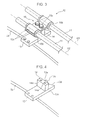
FIG. 2 is an enlarged perspective view of a part of a boom shown inFIG. 1 . -
FIG. 3 is an enlarged perspective view of a pipe supporting device shown inFIG. 2 . -
FIG. 4 is a perspective view of the pipe supporting device shown inFIG. 3 with a support portion thereof detached. -
FIG. 5 is a plan view of the configuration shown inFIG. 4 . -
FIG. 6 is an enlarged plan view of a part of the configuration shown inFIG. 5 . -
FIG. 7 is a diagram illustrating another welding method for the pipe supporting device in the first embodiment,FIG. 7 corresponding toFIG. 4 . -
FIG. 8 is an enlarged plan view of a part of the configuration shown inFIG. 7 . -
FIG. 9 is a diagram showing a pipe supporting device according to a second embodiment of the present invention,FIG. 9 corresponding toFIG. 7 . -
FIG. 10 is a diagram illustrating another welding method for the pipe supporting device in the second embodiment. -
FIG. 11 is a sectional view illustrating a state of an arm and a plate of a pipe supporting device connected with each other by welding which is disclosed in Patent Literature 1. -
FIG. 12 is an enlarged plan view of a part of the weld between the arm and the plate of the pipe supporting device which is disclosed in Patent Literature 1. - Hereinafter, embodiments of the present invention will be described with reference to the accompanying drawings. It should be noted that the following embodiments illustrate some examples of the invention, and not delimit the protection scope of the invention.
- With reference to
FIGS. 1 and2 , a hydraulic excavator 1, which exemplifies a construction machine according to an embodiment of the present invention, includes alower travelling body 2 having a pair ofcrawlers 2a, anupper slewing body 3 pivotally mounted on thelower travelling body 2, a working machine 4 movably mounted on theupper slewing body 3 and a pair of pipe supporting devices 12 (seeFIG. 2 ) supporting the hydraulic pipes 11 (seeFIG. 2 ) provided in the working machine 4. Thelower travelling body 2 and theupper slewing body 3 constitute a machine body pivotally supporting aboom 5 described later. - The working machine 4 includes the boom 5 (attachment) mounted to the
upper slewing body 3 pivotally around a horizontal axis J1, anarm 6 mounted to a distal end of theboom 5 pivotally around a horizontal axis, and abucket 7 mounted to a distal end of thearm 6 pivotally around a horizontal axis. - Further, the working machine 4 includes a
boom cylinder 8 for driving theboom 5 to move upward and downward with respect to theupper slewing body 3, anarm cylinder 9 for driving thearm 6 to pivot with respect to theboom 5, and abucket cylinder 10 for driving thebucket 7 to pivot with respect to thearm 6. - The
boom 5 is in the form of a cylinder having a closed section on a plane perpendicularly intersecting a length D1 of theboom 5. Specifically, theboom 5 includes a pair ofside plates 5a (only one of which is shown inFIG. 2 ) facing each other in the direction perpendicularly intersecting the length D1, atop plate 5b connecting respective upper ends of theside plates 5a, and abottom plate 5c connecting respective lower ends of theside plates 5a. In other words, the length D1 is on a vertically center line of theboom 5 connecting centers between thetop plate 5b and thebottom plate 5c. - Further, the
boom 5 includes aboss 5e to which a distal end of theboom cylinder 8 attached, and a pair ofbrackets 5d to which a base end of thearm cylinder 9 attached. Theboss 5e passes through theopposite side plates 5a, and is connected with theopposite side plates 5a by welding. Thebrackets 5d stand on thetop plate 5b and extend along the length D1, thebrackets 5d facing each other in the direction perpendicularly intersecting the length D1 (in the direction of theopposite side plates 5a facing each other). - When the working machine 4 performs excavation, a load acts on the distal end of the
boom 5 and theboom 5 is thus subject to bending. Consequently, a stress occurs in thetop plate 5b of theboom 5 in a first stress direction D3 (seeFIG. 5 ) along the length D1. - Further, in the excavation, a connecting pin which connects the
arm cylinder 9 and thebrackets 5d receives a force in the direction along the length D1, the force being a reaction force to a pulling movement of the arm 6 (extension of the arm cylinder 9). Here, respective lower ends of thebrackets 5d are secured on thetop plate 5b. Therefore, when the connecting pin receives the force, thebrackets 5d deform (incline) in such a way that respective upper ends of thebrackets 5d move away from each other. The portion of thetop plate 5b that is between theopposite brackets 5d (a widthwise middle portion of thetop plate 5b) bulges upward so that a bending deformation is occur on thetop plate 5b. As a result, a tensile stress occurs in thetop plate 5b in a second stress direction D4 (seeFIG. 5 ) perpendicularly intersecting the length D1. - The
hydraulic pipes 11 are disposed on thetop plate 5b of theboom 5 and along the length D1, and are respectively connected to thearm cylinder 9 and thebucket cylinder 10. - The pair of
pipe supporting devices 12 is disposed in widthwise symmetry as shown inFIG. 2 . Hereinafter, accordingly, only thepipe supporting device 12 on the left side will be described. -
FIG. 3 is a perspective view showing an overall configuration of thepipe supporting device 12.FIG. 4 is a perspective view of the pipe supporting device shown inFIG. 3 with asupport portion 15 thereof detached. - With reference to
FIGS. 3 and 4 , thepipe supporting device 12 includes thesupport portion 15 for supporting twohydraulic pipes 11 along respective axes D2 of the twohydraulic pipes 11, the axes extending along the length D1 of theboom 5, aweld portion 13 connected with an upper surface (outer surface) of thetop plate 5b of theboom 5 by fillet welding, and a connectingstand 14 connecting thesupport portion 15 and theweld portion 13. - The
support portion 15 includes a pair of upper andlower clamping plates 15a,buffers 15b respectively provided between the clampingplates 15a and each of thehydraulic pipes 11, and twobolts 15c securing theclamping plates 15a to the connectingstand 14. - The pair of clamping
plates 15a includes a pair of opposite upper and lower clamping portions (not denoted by a reference numeral) which define spaces respectively corresponding to the cross section of each of thehydraulic pipes 11, and insertion holes (not shown) formed between the clamping portions to allow thebolts 15c to pass therethrough. Thebolts 15c are inserted in the insertion holes from above and screwed intoscrew holes 14a (seeFIG. 4 ) formed in the connectingstand 14 to thereby connect theclamping plates 15a to the connectingstand 14 with thehydraulic pipes 11 being sandwiched between the opposite clamping portions of theclamping plates 15a. - Each of the
buffers 15b is provided between the inner surfaces of the clamping portions of theclamping plates 15a and the outer surface of the correspondinghydraulic pipe 11, to prevent thehydraulic pipes 11 from being damaged by the clamping portions. - As shown in
FIGS. 5 and 6 , theweld portion 13 is in the form of a metal plate and connected, by fillet welding, with thetop plate 5b by means of a weld bead B formed between peripheral surfaces of theweld portion 13 and the upper surface of thetop plate 5b of theboom 5. - For the fillet welding, the peripheral surfaces of the
weld portion 13 stand on thetop plate 5b and include a pair of oppositeperpendicular standing surfaces hydraulic pipe 11, and a pair of oblique standing surfaces 13c and 13d extending from respective leading ends of the pair of oppositeperpendicular standing surfaces hydraulic pipe 11. - The respective leading ends of the opposite
perpendicular standing surfaces hydraulic pipes 11 the same distance in a direction (i.e. the second stress direction D4) perpendicularly intersecting the axes D2. - The
oblique standing surface 13c joins theperpendicular standing surface 13a at an acute angle θ, and theoblique standing surface 13d also joins theperpendicular standing surface 13b at the acute angle θ. The angle θ is set at about 65 degrees. - The oblique standing surfaces 13c and 13d are flat and join each other to define an angle.
- Further, the oblique standing surfaces 13c and 13d are symmetrically disposed with respect to a straight line L1 through which a plane passing the middle between the pair of opposite
perpendicular standing surfaces hydraulic pipes 11 passes. In other words, the oblique standing surfaces 13c and 13d have the same length and are disposed at the same angle. - The above-described
pipe supporting device 12 is connected to theboom 5 by fillet welding, for example, as described below. - In order to support the
hydraulic pipes 11 along their axes D2 (seeFIG. 2 ) of thehydraulic pipes 11, theweld portion 13 is disposed on thetop plate 5b of theboom 5 in such a way that the oppositeperpendicular standing surfaces weld portion 13 perpendicularly intersect the first stress direction D3 on thetop plate 5b. This allows the oblique standing surfaces 13c and 13d to be disposed obliquely to the first stress direction D3 and the second stress direction D4. - Here, one end of the
weld portion 13 along the second stress direction D4 is located at an outer position than the widthwise middle of thetop plate 5b in the second stress direction D4, and the other end of theweld portion 13 is located outwardly beyond the side end of thetop plate 5b. - In this state, the
weld portion 13 is connected to thetop plate 5b by fillet welding (a weld bead B is formed) along theperpendicular standing surface 13a, theoblique standing surface 13c, theoblique standing surface 13d, and theperpendicular standing surface 13b over a range including theperpendicular standing surface 13a, theoblique standing surface 13c, theoblique standing surface 13d, and theperpendicular standing surface 13b. - Specifically, the weld bead B includes perpendicular portions B1 (the hatched portion in
FIG. 6 ) respectively formed along theperpendicular standing surfaces FIG. 6 ) respectively formed along the oblique standing surfaces 13c and 13d, and corner portions B3 (the cross-hatched portion inFIG. 6 ) respectively formed at each of the corner between theperpendicular standing surface 13a and theoblique standing surface 13c and the corner between theperpendicular standing surface 13b and theoblique standing surface 13d. The perpendicular portions B1 are respectively formed along a part of each of theperpendicular standing surfaces - In the case of forming the weld bead B in the manner described above, the strength of the weld is liable to be insufficient because the opposite
perpendicular standing surfaces - Further, stress concentration is liable to occur at the weld formed at each of the corner between the
perpendicular standing surface 13a and theoblique standing surface 13c and the corner between theperpendicular standing surface 13b and theoblique standing surface 13d. Therefore, also the corner portions B3 need to be ground by the grinder G. - On the other hand, because the oblique standing surfaces 13c and 13d extend obliquely to both of the stress directions D3 and D4, the oblique portions B2 do not need to be ground.
- As described above, a stress occurs in the
top plate 5b of theboom 5 in the second stress direction D4, owing to the upward deformation of thetop plate 5b at the middle portion thereof. Therefore, the stress in the second stress direction D4 increases as approaching the middle of theboom 5. Here, stress concentration is liable to occur at the weld also at the corner (hereinafter, also referred to as "inner corner") between the oblique standing surfaces 13c and 13d. However, the inner corner is more distant from the middle portion of thetop plate 5b than each of the corners (hereinafter, also referred to as "outer corners") between theperpendicular standing surface 13a and theoblique standing surface 13c and between theperpendicular standing surface 13b and theoblique standing surface 13d. Therefore, the inner corner has a more favorable strength than the outer corners, which makes it possible to omit grinding of the weld also at the inner corner. - In view of the above, as shown in
FIG. 6 , a treatment G1 by the grinder G is performed on the perpendicular portions B1 and a treatment G2 by the grinder G is performed on the corner portions B3, a terminating end G3 of the treatment G2 being set at the boundary between the corner portion B3 and the oblique portion B2. - At this time, the grinder G is caused to move in the second stress direction D4 while reciprocating in the first stress direction D3 to thereby perform the treatments G1 and G2 on the perpendicular portions B1 and the corner portions B3, respectively.
- Further, in order that the corner portion B3 joins the oblique portion B2 without a step at each of the terminating ends G3, a finishing treatment is performed on the terminating ends G3 by moving the grinder G in the first stress direction D3. Here, because the
oblique standing surface 13c (13d) joins theperpendicular standing surface 13a (13b) at the acute angle in theweld portion 13, theoblique surface 13c (13d) is not located in the middle of the path of movement of the grinder G in the first stress direction D3. This allows the grinder G to perform the finishing treatment without making contact with theoblique standing surface 13c (13d). - A finishing treatment can be easily performed also in the case where the above-described
pipe supporting device 12 is welded to theboom 5 in the manner shown inFIGS. 7 and 8 . - A weld bead B shown in
FIGS. 7 and 8 includes oblique portions B2 (the blank portion inFIG. 8 ) respectively formed along the oblique standing surfaces 13c and 13d, and extension portions B4 (the cross-hatched portion inFIG. 8 ) respectively extending from each of the oblique portions B2 beyond the corresponding one of the corner between theperpendicular standing surface 13a and theoblique standing surface 13c and the corner between theperpendicular standing surface 13b and theoblique standing surface 13d, the weld bead B having no such perpendicular portions B 1 as described. - Each of the extension portions B4 includes a part protruding from the
weld portion 13 to receive a concentrated stress, and another part contributing to the welding of the corresponding one of the corner between theperpendicular standing surface 13a and theoblique standing surface 13c and the corner between theperpendicular standing surface 13b and theoblique standing surface 13d. Accordingly, a treatment G4 by the grinder G is performed on the extension portions B4, and a terminating end G5 of the treatment G4 is set at the boundary between the extension portion B4 and the oblique portion B2. - In the same manner as the above-described case, the grinder G is reciprocatingly moved in the first stress direction D3 to thereby perform the treatment G4.
- Further, in order that the oblique portion B2 joins the corresponding extension portion B4 without a step at each of the terminating ends G5, a finishing treatment is performed on the terminating ends G5 by moving the grinder G in the first stress direction D3. Also in this case, the
oblique surface 13c (13d) is not located in the middle of the path of movement of the grinder G. Therefore, the finishing treatment can be easily performed. - However, a larger area can be secured for welding to allow a more favorable strength in the case shown in
FIGS. 5 and 6 than in the case shown inFIG. 7 and 8 . - As described above, the oblique standing surfaces 13c and 13d join the
perpendicular standing surfaces hydraulic pipes 11 to perform the treatment G2 on the corner portions B3. This allows the grinder G to perform the finishing treatment on the terminating ends of the grinding, without making contact with the oblique standing surfaces 13c and 13d. - Therefore, it is possible to easily perform the finishing treatment on the terminating ends of the grinding performed on the weld formed on the
boom 5. - According to the first embodiment, the following advantageous effects can be provided.
- The oblique standing surfaces 13c and 13d have the same length and are disposed at the same oblique angle. This is effective to decentralize a stress occurring at the welds respectively formed at the oblique standing surfaces 13c and 13d.
- Therefore, it is possible to secure a sufficient strength of the weld formed at the oblique standing surfaces 13c and 13d without performing grinding thereon by the grinder G.
- In the first embodiment, the pair of oblique standing surfaces 13c and 13d of the
weld portion 13 join each other to define an angle. However, a pair of oblique standing surfaces may include respective curved portions joining each other, as illustrated as a second embodiment. - Specifically, a
weld portion 13 according to the second embodiment includes acurved standing surface 13e connecting respective leading ends ofperpendicular standing surfaces curved standing surface 13e is parabolic in a plan view. - Specifically, the
curved standing surface 13e has an oblique portion (not denoted by a reference numeral) joining theperpendicular standing surface 13a at an acute angle, another oblique portion (not denoted by a reference numeral) joining theperpendicular standing surface 13b at an acute angle, and a connecting portion (not denoted by a reference numeral) located between the oblique portions, the connecting portion consisting of joining curved portions. - A pipe supporting device according to the second embodiment can be connected to the
boom 5 by fillet welding in the manner described below. - As shown in
FIG. 9 , it is possible to connect theweld portion 13 to thetop plate 5b by means of a weld bead B including a curved portion B5 formed along thecurved standing surface 13e, and extension portions B6 respectively extending from opposite ends of the curved portion B5 beyond the corner between thecurved standing surface 13e and each of theperpendicular standing surfaces FIG. 8 , a terminating end of a treatment performed by the grinder G is set at the boundary between the curved portion B5 and each of the extension portions B6. Therefore, a finishing treatment can be easily performed on the terminating ends. - Further, as shown in
FIG. 10 , it is possible to connect theweld portion 13 to thetop plate 5b by means of a weld bead B including a curved portion B5 formed along thecurved standing surface 13e, perpendicular portions B7 respectively formed along theperpendicular standing surfaces FIG. 6 , a terminating end of a treatment performed by the grinder G is set at the boundary between the perpendicular portion B7 and the corner portion B8. Therefore, a finishing treatment can be easily performed on the terminating ends. - According to the second embodiment, in the
curved standing surface 13e, one oblique portion joins another oblique portion via the curved connecting portion, which ensures a gradual change in angle. This makes it possible to reduce the stress concentration at the joining portion, compared to the case where the oblique standing surfaces join each other at a definite angle. - The present invention is not limited to the above-described embodiments and the following modifications may be adopted.
- In the above-described embodiments, each of the
perpendicular standing surfaces curved standing surface 13e at a definite angle. However, theperpendicular standing surfaces oblique standing surfaces curved standing surface 13e may be modified to include respective curved portions at their respective joining portions. - In the above-described embodiments, the
pipe supporting device 12 is connected to theboom 5 by fillet welding. However, thepipe supporting device 12 may be mounted to thearm 6. - In the above-described embodiments, the respective leading ends of the
perpendicular standing surfaces hydraulic pipe 11 in the second stress direction D4. However, the configuration may be modified so that the leading end of theperpendicular standing surface 13a is disposed at a different position. In this state, it is possible to set the respective oblique angles of the oblique standing surfaces 13c and 13d so that the oblique standing surfaces 13c and 13d have the same length. On the other hand, it is also possible to set the joining point of the oblique standing surfaces 13c and 13d so that the oblique standing surfaces 13c and 13d have different lengths but have the same oblique angle. - The configuration that the oblique standing surfaces include respective curved portions joining each other has been illustrated by the
curved standing surface 13e. However, the configuration may be modified so that flat oblique standing surfaces 13c and 13e include respective curved portions at their respective joining ends. - The above-described specific embodiments mainly include the invention configured as follows.
- The present invention provides a pipe supporting device for use in a construction machine including a machine body, an attachment mounted on the machine body pivotably around a horizontal axis, and a hydraulic pipe extending along a length of the attachment, the pipe supporting device comprising: a support portion for supporting the hydraulic pipe along an axis of the hydraulic pipe extending along the length of the attachment; and a weld portion joining the support portion and to be connected with an outer surface of the attachment by fillet welding, wherein the weld portion has a plurality of peripheral surfaces standing on the outer surface of the attachment for the fillet welding, the plurality of peripheral surfaces including: a pair of opposite perpendicular standing surfaces extending in a direction substantially perpendicularly intersecting the axis of the hydraulic pipe; and a pair of oblique standing surfaces extending from respective leading ends of the pair of opposite perpendicular standing surfaces to join each other, each of the oblique surfaces extending in a direction oblique to the axis of the hydraulic pipe and joining the corresponding perpendicular standing surface at an acute angle.
- In the present invention, the axis of the hydraulic pipe extending along the length of the attachment extends in a direction of a stress occurring in the attachment. Because each of the pair of oblique standing surfaces extends obliquely to the stress direction, the connecting of the oblique standing surfaces to the attachment by welding allows the pipe supporting device to be secured on the attachment with the weld having a sufficient strength against the stress.
- Further, because the strength of weld can be secured in this way, the weld formed between the oblique standing surfaces and the attachment does not need to be ground by a grinder.
- On the other hand, stress concentration is liable to occur at the weld formed between the corners between the pair of perpendicular standing surfaces and the pair of oblique standing surfaces, and the attachment. Therefore, the weld formed at each of the corners needs to be ground by the grinder.
- Accordingly, in the case where the pipe supporting device according to the present invention is connected to the attachment by welding, a terminating end of the grinding performed by the grinder is set at the boundary between the weld formed at each of the corners and the weld formed at the corresponding oblique standing surface.
- Here, the grinding of the weld formed at each of the corners is performed by reciprocatingly moving the grinder along the axis of the hydraulic pipe (in the direction perpendicularly intersecting the perpendicular standing surfaces).
- In the present invention, each of the oblique standing surfaces joins the corresponding perpendicular standing surface at an acute angle. Therefore, the oblique surfaces are not located in the middle of the path of movement when the grinder is moved along the axis of the hydraulic pipe to perform a treatment on the weld formed at each of the corners. This allows the grinder to perform a finishing treatment on the terminating ends of the grinding, without making contact with the oblique standing surfaces.
- Therefore, according to the present embodiment, it is possible to easily perform a finishing treatment on a terminating end of grinding performed on a weld formed on an attachment.
- In the present embodiment, it should be noted that the expression "each of the oblique standing surfaces joins the corresponding perpendicular standing surface at an acute angle" includes not only a configuration where an oblique standing surface joins a perpendicular standing surface at a definite angle, but also a configuration where an oblique standing surface and a perpendicular standing surface join each other curvedly or without a definite angle.
- Here, even if the pair of oblique standing surfaces differ from each other in at least one of length and oblique angle, the above-described advantageous effects can be obtained as long as each of the oblique standing surface joins the corresponding perpendicular standing surface at an acute angle. However, in this case, because the pair of oblique standing surfaces differ from each other in length or oblique angle, stress concentration is liable to occur at one of the welds respectively formed at each of the oblique standing surfaces.
- Accordingly, in the above-described pipe supporting device, it is preferred that the respective leading ends of the pair of opposite perpendicular standing surfaces are located at positions away from the axis of the hydraulic pipe the same distance in the direction perpendicularly intersecting the axis of the hydraulic pipe, and that the pair of oblique standing surfaces are symmetrically disposed with respect to a joint line through which a plane passing a middle between the pair of opposite perpendicular standing surfaces and perpendicularly intersecting the axis of the hydraulic pipe passes.
- According to this configuration, the pair of oblique standing surfaces have the same length and are disposed at the same oblique angle. This is effective to decentralize a stress occurring at the welds formed at the oblique standing surfaces.
- Therefore, it is possible to secure a sufficient strength of the weld formed at the oblique standing surfaces without performing grinding thereon by the grinder.
- Here, the pair of oblique standing surfaces may join each other at a definite angle. However, in this case, stress concentration is liable to occur at the weld formed at the angle.
- Accordingly, in the above-described pipe supporting device, it is preferred that the pair of oblique standing surfaces include respective curved portions joining each other.
- According to this configuration, one oblique standing surface joins another oblique standing surface at gradually changing angles. This makes it possible to reduce stress concentration at the joining portion, compared to the case where the oblique standing surfaces join each other at a definite angle.
- This application is based on Japanese Patent application No.
2014-127950 - Although the present invention has been fully described by way of example with reference to the accompanying drawings, it is to be understood that various changes and modifications will be apparent to those skilled in the art. Therefore, unless otherwise such changes and modifications depart from the scope of the present invention hereinafter defined, they should be construed as being included therein.
- A pipe supporting device is provided which allows a finishing treatment to be easily performed on a terminating end of grinding performed on a weld formed on an attachment. A
pipe supporting device 12 includes asupport portion 15 for supporting ahydraulic pipe 11 along an axis D2 of thehydraulic pipe 11 extending along a length D1 of aboom 5, and aweld portion 13 joining thesupport portion 15 and to be connected with an outer surface of theboom 5 by fillet welding. Theweld portion 13 has a plurality of peripheral surfaces standing on the outer surface of theboom 5 for the fillet welding, the plurality of peripheral surfaces including: a pair of oppositeperpendicular standing surfaces hydraulic pipe 11; and a pair of oblique standing surfaces 13c and 13d extending from respective leading ends of the pair of oppositeperpendicular standing surfaces perpendicular standing surfaces
Claims (3)
- A pipe supporting device for use in a construction machine including a machine body, an attachment mounted on the machine body pivotably around a horizontal axis, and a hydraulic pipe extending along a length of the attachment, the pipe supporting device comprising:a support portion for supporting the hydraulic pipe along an axis of the hydraulic pipe extending along the length of the attachment; anda weld portion joining the support portion and to be connected with an outer surface of the attachment by fillet welding, whereinthe weld portion has a plurality of peripheral surfaces standing on the outer surface of the attachment for the fillet welding, the plurality of peripheral surfaces including: a pair of opposite perpendicular standing surfaces extending in a direction substantially perpendicularly intersecting the axis of the hydraulic pipe; and a pair of oblique standing surfaces extending from respective leading ends of the pair of opposite perpendicular standing surfaces to join each other, each of the oblique standing surfaces extending in a direction oblique to the axis of the hydraulic pipe and joining the corresponding perpendicular standing surface at an acute angle.
- A pipe supporting device according to claim 1, wherein
the respective leading ends of the pair of opposite perpendicular standing surfaces are located at positions away from the axis of the hydraulic pipe the same distance in the direction perpendicularly intersecting the axis of the hydraulic pipe, and
the pair of oblique standing surfaces are symmetrically disposed with respect to a joint line through which a plane passing a middle between the pair of opposite perpendicular standing surfaces and perpendicularly intersecting the axis of the hydraulic pipe passes. - A pipe supporting device according to claim 1 or 2, wherein
the pair of oblique standing surfaces include respective curved portions joining each other.
Applications Claiming Priority (1)
| Application Number | Priority Date | Filing Date | Title |
|---|---|---|---|
| JP2014127950A JP5962710B2 (en) | 2014-06-23 | 2014-06-23 | Piping support for construction machinery |
Publications (2)
| Publication Number | Publication Date |
|---|---|
| EP2960378A1 true EP2960378A1 (en) | 2015-12-30 |
| EP2960378B1 EP2960378B1 (en) | 2018-04-25 |
Family
ID=53938046
Family Applications (1)
| Application Number | Title | Priority Date | Filing Date |
|---|---|---|---|
| EP15172639.5A Not-in-force EP2960378B1 (en) | 2014-06-23 | 2015-06-18 | Pipe supporting device for construction machine |
Country Status (4)
| Country | Link |
|---|---|
| US (1) | US9482253B2 (en) |
| EP (1) | EP2960378B1 (en) |
| JP (1) | JP5962710B2 (en) |
| CN (1) | CN105201035B (en) |
Families Citing this family (10)
| Publication number | Priority date | Publication date | Assignee | Title |
|---|---|---|---|---|
| US9788667B2 (en) * | 2013-07-16 | 2017-10-17 | Fasteners For Retail, Inc. | Lock for securing front rail to wire shelving |
| US9670949B1 (en) * | 2015-08-03 | 2017-06-06 | James C. White Company, Inc. | Keyhole weld-down fastener base |
| US10281054B2 (en) * | 2017-09-15 | 2019-05-07 | Caterpillar Inc. | Valve guard for valve assembly |
| NL2019747B1 (en) * | 2017-10-17 | 2019-04-24 | Walraven Holding Bv J Van | Riser clamp with a vibration isolation element |
| US10703311B2 (en) | 2018-07-03 | 2020-07-07 | Caterpillar Sarl | Hydraulic hose clamp assembly |
| US11384867B2 (en) * | 2019-03-27 | 2022-07-12 | Great Plains Manufacturing, Inc. | Hydraulic hose clamp |
| US11635333B2 (en) * | 2021-03-25 | 2023-04-25 | Raytheon Technologies Corporation | Low-profile sensor circuit mounting fixture |
| JP2024137143A (en) * | 2023-03-24 | 2024-10-07 | 株式会社小松製作所 | Boom for work implement, work machine, and method for manufacturing boom for work implement |
| US20250251059A1 (en) * | 2024-02-07 | 2025-08-07 | Tom Nepola | High vibration clamp assembly |
| CN119352595B (en) * | 2024-11-28 | 2025-10-14 | 雷沃重工集团有限公司 | An excavator bucket arm |
Citations (5)
| Publication number | Priority date | Publication date | Assignee | Title |
|---|---|---|---|---|
| JPH0510547U (en) * | 1991-07-18 | 1993-02-12 | 油谷重工株式会社 | Pipe clamp device |
| JP2004169864A (en) * | 2002-11-21 | 2004-06-17 | Nippon Steel Corp | bracket |
| EP1607528A2 (en) * | 2004-06-14 | 2005-12-21 | Komatsu Ltd | Component support device and construction machine with component attached via the same |
| JP2007120194A (en) * | 2005-10-28 | 2007-05-17 | Komatsu Ltd | Component support, component support structure and construction machine |
| EP2573277A1 (en) * | 2010-05-17 | 2013-03-27 | Volvo Construction Equipment AB | Fixing device of hydraulic pipe of construction machine |
Family Cites Families (10)
| Publication number | Priority date | Publication date | Assignee | Title |
|---|---|---|---|---|
| US3851672A (en) * | 1973-05-18 | 1974-12-03 | Gen Motors Corp | Hose assembly with prepositioned hose mounting bracket |
| US4395193A (en) * | 1981-04-03 | 1983-07-26 | Dresser Industries, Inc. | Material handling bucket |
| US5222701A (en) * | 1988-04-01 | 1993-06-29 | Rowland David E | Wall mounted support for holding articles |
| JPH051790A (en) * | 1991-06-21 | 1993-01-08 | Hitachi Constr Mach Co Ltd | Clamping device for hydraulic piping |
| JPH05196176A (en) * | 1992-01-17 | 1993-08-06 | Hitachi Constr Mach Co Ltd | Screw wahser for fixing piping of construction machine |
| JP4648768B2 (en) * | 2004-06-14 | 2011-03-09 | 株式会社小松製作所 | Component support device and construction machine to which components are attached via the component support device |
| DE102005002715A1 (en) * | 2005-01-20 | 2006-08-03 | Krones Ag | Method and device for holding vessels |
| KR101121706B1 (en) * | 2009-10-26 | 2012-03-09 | 볼보 컨스트럭션 이큅먼트 에이비 | fixing device of hydraulic pipe of construction equipment |
| JP5530730B2 (en) * | 2010-01-22 | 2014-06-25 | 株式会社神戸製鋼所 | Working arm and work machine equipped with the same |
| CN103075576B (en) * | 2013-01-22 | 2015-04-29 | 广西柳工机械股份有限公司 | Pipeline fixing device |
-
2014
- 2014-06-23 JP JP2014127950A patent/JP5962710B2/en active Active
-
2015
- 2015-06-15 US US14/739,400 patent/US9482253B2/en not_active Expired - Fee Related
- 2015-06-18 EP EP15172639.5A patent/EP2960378B1/en not_active Not-in-force
- 2015-06-23 CN CN201510349250.0A patent/CN105201035B/en active Active
Patent Citations (6)
| Publication number | Priority date | Publication date | Assignee | Title |
|---|---|---|---|---|
| JPH0510547U (en) * | 1991-07-18 | 1993-02-12 | 油谷重工株式会社 | Pipe clamp device |
| JP2004169864A (en) * | 2002-11-21 | 2004-06-17 | Nippon Steel Corp | bracket |
| EP1607528A2 (en) * | 2004-06-14 | 2005-12-21 | Komatsu Ltd | Component support device and construction machine with component attached via the same |
| JP2007120194A (en) * | 2005-10-28 | 2007-05-17 | Komatsu Ltd | Component support, component support structure and construction machine |
| JP4704888B2 (en) | 2005-10-28 | 2011-06-22 | 株式会社小松製作所 | Component support, component support structure and construction machine |
| EP2573277A1 (en) * | 2010-05-17 | 2013-03-27 | Volvo Construction Equipment AB | Fixing device of hydraulic pipe of construction machine |
Also Published As
| Publication number | Publication date |
|---|---|
| CN105201035B (en) | 2018-11-09 |
| CN105201035A (en) | 2015-12-30 |
| US20150369396A1 (en) | 2015-12-24 |
| EP2960378B1 (en) | 2018-04-25 |
| JP5962710B2 (en) | 2016-08-03 |
| US9482253B2 (en) | 2016-11-01 |
| JP2016008622A (en) | 2016-01-18 |
Similar Documents
| Publication | Publication Date | Title |
|---|---|---|
| EP2960378B1 (en) | Pipe supporting device for construction machine | |
| US9458606B2 (en) | Boom apparatus with protective barrier for flexible line | |
| JP4679605B2 (en) | Hydraulic hose routing device for hanging grapple | |
| KR200469569Y1 (en) | Tongs apparatus for excavator | |
| CN104416261A (en) | Welding assembly and method for manufacturing same | |
| KR20100137559A (en) | Cap of construction machinery | |
| CN105164342B (en) | Rotating frame and working machine including the frame | |
| KR20090092585A (en) | Upper frame of construction equipment | |
| US20170233979A1 (en) | Dipper handle cross member | |
| KR101786078B1 (en) | Arm center boss controlling generation of fatigue crack | |
| JP6834969B2 (en) | Boom for work machinery | |
| JP2016003443A (en) | Revolving frame of construction machine | |
| CN102051894B (en) | Upper frame of construction machine | |
| JP2015199427A (en) | work machine | |
| US9366006B2 (en) | Bucket for work vehicle, and work vehicle equipped with bucket with left and right boom attachment portions | |
| JP6013286B2 (en) | Work equipment boom | |
| CN113840963A (en) | Frame of construction machine | |
| JP6305846B2 (en) | Attachment component, attachment of construction machine equipped with the same, and method of manufacturing attachment | |
| JP6260325B2 (en) | Can manufacturing structure and construction machinery | |
| CN108884654A (en) | The box-like construction body of equipment | |
| JP2001239964A (en) | Truck frame of crawler type vehicle | |
| JP6301754B2 (en) | Plate material, attachment for construction machine equipped with the same, and method for manufacturing attachment | |
| US20130051965A1 (en) | Articulated work machine | |
| KR101942213B1 (en) | Mounting structure of new boom | |
| JP5949131B2 (en) | Work machine |
Legal Events
| Date | Code | Title | Description |
|---|---|---|---|
| PUAI | Public reference made under article 153(3) epc to a published international application that has entered the european phase |
Free format text: ORIGINAL CODE: 0009012 |
|
| 17P | Request for examination filed |
Effective date: 20150618 |
|
| AK | Designated contracting states |
Kind code of ref document: A1 Designated state(s): AL AT BE BG CH CY CZ DE DK EE ES FI FR GB GR HR HU IE IS IT LI LT LU LV MC MK MT NL NO PL PT RO RS SE SI SK SM TR |
|
| AX | Request for extension of the european patent |
Extension state: BA ME |
|
| GRAP | Despatch of communication of intention to grant a patent |
Free format text: ORIGINAL CODE: EPIDOSNIGR1 |
|
| INTG | Intention to grant announced |
Effective date: 20171113 |
|
| RIN1 | Information on inventor provided before grant (corrected) |
Inventor name: HANDA, ISAO Inventor name: KOSAKA, KYOHEI |
|
| GRAA | (expected) grant |
Free format text: ORIGINAL CODE: 0009210 |
|
| GRAS | Grant fee paid |
Free format text: ORIGINAL CODE: EPIDOSNIGR3 |
|
| AK | Designated contracting states |
Kind code of ref document: B1 Designated state(s): AL AT BE BG CH CY CZ DE DK EE ES FI FR GB GR HR HU IE IS IT LI LT LU LV MC MK MT NL NO PL PT RO RS SE SI SK SM TR |
|
| REG | Reference to a national code |
Ref country code: GB Ref legal event code: FG4D |
|
| REG | Reference to a national code |
Ref country code: CH Ref legal event code: EP |
|
| REG | Reference to a national code |
Ref country code: AT Ref legal event code: REF Ref document number: 993066 Country of ref document: AT Kind code of ref document: T Effective date: 20180515 |
|
| REG | Reference to a national code |
Ref country code: IE Ref legal event code: FG4D |
|
| REG | Reference to a national code |
Ref country code: DE Ref legal event code: R096 Ref document number: 602015010307 Country of ref document: DE |
|
| REG | Reference to a national code |
Ref country code: FR Ref legal event code: PLFP Year of fee payment: 4 |
|
| REG | Reference to a national code |
Ref country code: NL Ref legal event code: MP Effective date: 20180425 |
|
| REG | Reference to a national code |
Ref country code: LT Ref legal event code: MG4D |
|
| PG25 | Lapsed in a contracting state [announced via postgrant information from national office to epo] |
Ref country code: NL Free format text: LAPSE BECAUSE OF FAILURE TO SUBMIT A TRANSLATION OF THE DESCRIPTION OR TO PAY THE FEE WITHIN THE PRESCRIBED TIME-LIMIT Effective date: 20180425 |
|
| PG25 | Lapsed in a contracting state [announced via postgrant information from national office to epo] |
Ref country code: BG Free format text: LAPSE BECAUSE OF FAILURE TO SUBMIT A TRANSLATION OF THE DESCRIPTION OR TO PAY THE FEE WITHIN THE PRESCRIBED TIME-LIMIT Effective date: 20180725 Ref country code: NO Free format text: LAPSE BECAUSE OF FAILURE TO SUBMIT A TRANSLATION OF THE DESCRIPTION OR TO PAY THE FEE WITHIN THE PRESCRIBED TIME-LIMIT Effective date: 20180725 Ref country code: FI Free format text: LAPSE BECAUSE OF FAILURE TO SUBMIT A TRANSLATION OF THE DESCRIPTION OR TO PAY THE FEE WITHIN THE PRESCRIBED TIME-LIMIT Effective date: 20180425 Ref country code: ES Free format text: LAPSE BECAUSE OF FAILURE TO SUBMIT A TRANSLATION OF THE DESCRIPTION OR TO PAY THE FEE WITHIN THE PRESCRIBED TIME-LIMIT Effective date: 20180425 Ref country code: SE Free format text: LAPSE BECAUSE OF FAILURE TO SUBMIT A TRANSLATION OF THE DESCRIPTION OR TO PAY THE FEE WITHIN THE PRESCRIBED TIME-LIMIT Effective date: 20180425 Ref country code: PL Free format text: LAPSE BECAUSE OF FAILURE TO SUBMIT A TRANSLATION OF THE DESCRIPTION OR TO PAY THE FEE WITHIN THE PRESCRIBED TIME-LIMIT Effective date: 20180425 Ref country code: LT Free format text: LAPSE BECAUSE OF FAILURE TO SUBMIT A TRANSLATION OF THE DESCRIPTION OR TO PAY THE FEE WITHIN THE PRESCRIBED TIME-LIMIT Effective date: 20180425 |
|
| PG25 | Lapsed in a contracting state [announced via postgrant information from national office to epo] |
Ref country code: LV Free format text: LAPSE BECAUSE OF FAILURE TO SUBMIT A TRANSLATION OF THE DESCRIPTION OR TO PAY THE FEE WITHIN THE PRESCRIBED TIME-LIMIT Effective date: 20180425 Ref country code: GR Free format text: LAPSE BECAUSE OF FAILURE TO SUBMIT A TRANSLATION OF THE DESCRIPTION OR TO PAY THE FEE WITHIN THE PRESCRIBED TIME-LIMIT Effective date: 20180726 Ref country code: HR Free format text: LAPSE BECAUSE OF FAILURE TO SUBMIT A TRANSLATION OF THE DESCRIPTION OR TO PAY THE FEE WITHIN THE PRESCRIBED TIME-LIMIT Effective date: 20180425 Ref country code: RS Free format text: LAPSE BECAUSE OF FAILURE TO SUBMIT A TRANSLATION OF THE DESCRIPTION OR TO PAY THE FEE WITHIN THE PRESCRIBED TIME-LIMIT Effective date: 20180425 |
|
| REG | Reference to a national code |
Ref country code: AT Ref legal event code: MK05 Ref document number: 993066 Country of ref document: AT Kind code of ref document: T Effective date: 20180425 |
|
| PG25 | Lapsed in a contracting state [announced via postgrant information from national office to epo] |
Ref country code: PT Free format text: LAPSE BECAUSE OF FAILURE TO SUBMIT A TRANSLATION OF THE DESCRIPTION OR TO PAY THE FEE WITHIN THE PRESCRIBED TIME-LIMIT Effective date: 20180827 |
|
| REG | Reference to a national code |
Ref country code: DE Ref legal event code: R097 Ref document number: 602015010307 Country of ref document: DE |
|
| PG25 | Lapsed in a contracting state [announced via postgrant information from national office to epo] |
Ref country code: DK Free format text: LAPSE BECAUSE OF FAILURE TO SUBMIT A TRANSLATION OF THE DESCRIPTION OR TO PAY THE FEE WITHIN THE PRESCRIBED TIME-LIMIT Effective date: 20180425 Ref country code: AT Free format text: LAPSE BECAUSE OF FAILURE TO SUBMIT A TRANSLATION OF THE DESCRIPTION OR TO PAY THE FEE WITHIN THE PRESCRIBED TIME-LIMIT Effective date: 20180425 Ref country code: EE Free format text: LAPSE BECAUSE OF FAILURE TO SUBMIT A TRANSLATION OF THE DESCRIPTION OR TO PAY THE FEE WITHIN THE PRESCRIBED TIME-LIMIT Effective date: 20180425 Ref country code: RO Free format text: LAPSE BECAUSE OF FAILURE TO SUBMIT A TRANSLATION OF THE DESCRIPTION OR TO PAY THE FEE WITHIN THE PRESCRIBED TIME-LIMIT Effective date: 20180425 Ref country code: CZ Free format text: LAPSE BECAUSE OF FAILURE TO SUBMIT A TRANSLATION OF THE DESCRIPTION OR TO PAY THE FEE WITHIN THE PRESCRIBED TIME-LIMIT Effective date: 20180425 Ref country code: SK Free format text: LAPSE BECAUSE OF FAILURE TO SUBMIT A TRANSLATION OF THE DESCRIPTION OR TO PAY THE FEE WITHIN THE PRESCRIBED TIME-LIMIT Effective date: 20180425 |
|
| REG | Reference to a national code |
Ref country code: CH Ref legal event code: PL |
|
| PG25 | Lapsed in a contracting state [announced via postgrant information from national office to epo] |
Ref country code: SM Free format text: LAPSE BECAUSE OF FAILURE TO SUBMIT A TRANSLATION OF THE DESCRIPTION OR TO PAY THE FEE WITHIN THE PRESCRIBED TIME-LIMIT Effective date: 20180425 |
|
| PLBE | No opposition filed within time limit |
Free format text: ORIGINAL CODE: 0009261 |
|
| STAA | Information on the status of an ep patent application or granted ep patent |
Free format text: STATUS: NO OPPOSITION FILED WITHIN TIME LIMIT |
|
| REG | Reference to a national code |
Ref country code: BE Ref legal event code: MM Effective date: 20180630 |
|
| REG | Reference to a national code |
Ref country code: IE Ref legal event code: MM4A |
|
| PG25 | Lapsed in a contracting state [announced via postgrant information from national office to epo] |
Ref country code: LU Free format text: LAPSE BECAUSE OF NON-PAYMENT OF DUE FEES Effective date: 20180618 Ref country code: MC Free format text: LAPSE BECAUSE OF FAILURE TO SUBMIT A TRANSLATION OF THE DESCRIPTION OR TO PAY THE FEE WITHIN THE PRESCRIBED TIME-LIMIT Effective date: 20180425 |
|
| 26N | No opposition filed |
Effective date: 20190128 |
|
| PG25 | Lapsed in a contracting state [announced via postgrant information from national office to epo] |
Ref country code: LI Free format text: LAPSE BECAUSE OF NON-PAYMENT OF DUE FEES Effective date: 20180630 Ref country code: IE Free format text: LAPSE BECAUSE OF NON-PAYMENT OF DUE FEES Effective date: 20180618 Ref country code: CH Free format text: LAPSE BECAUSE OF NON-PAYMENT OF DUE FEES Effective date: 20180630 |
|
| PG25 | Lapsed in a contracting state [announced via postgrant information from national office to epo] |
Ref country code: BE Free format text: LAPSE BECAUSE OF NON-PAYMENT OF DUE FEES Effective date: 20180630 Ref country code: SI Free format text: LAPSE BECAUSE OF FAILURE TO SUBMIT A TRANSLATION OF THE DESCRIPTION OR TO PAY THE FEE WITHIN THE PRESCRIBED TIME-LIMIT Effective date: 20180425 |
|
| PG25 | Lapsed in a contracting state [announced via postgrant information from national office to epo] |
Ref country code: AL Free format text: LAPSE BECAUSE OF FAILURE TO SUBMIT A TRANSLATION OF THE DESCRIPTION OR TO PAY THE FEE WITHIN THE PRESCRIBED TIME-LIMIT Effective date: 20180425 |
|
| PG25 | Lapsed in a contracting state [announced via postgrant information from national office to epo] |
Ref country code: MT Free format text: LAPSE BECAUSE OF NON-PAYMENT OF DUE FEES Effective date: 20180618 |
|
| PG25 | Lapsed in a contracting state [announced via postgrant information from national office to epo] |
Ref country code: TR Free format text: LAPSE BECAUSE OF FAILURE TO SUBMIT A TRANSLATION OF THE DESCRIPTION OR TO PAY THE FEE WITHIN THE PRESCRIBED TIME-LIMIT Effective date: 20180425 |
|
| PG25 | Lapsed in a contracting state [announced via postgrant information from national office to epo] |
Ref country code: HU Free format text: LAPSE BECAUSE OF FAILURE TO SUBMIT A TRANSLATION OF THE DESCRIPTION OR TO PAY THE FEE WITHIN THE PRESCRIBED TIME-LIMIT; INVALID AB INITIO Effective date: 20150618 Ref country code: CY Free format text: LAPSE BECAUSE OF FAILURE TO SUBMIT A TRANSLATION OF THE DESCRIPTION OR TO PAY THE FEE WITHIN THE PRESCRIBED TIME-LIMIT Effective date: 20180425 Ref country code: MK Free format text: LAPSE BECAUSE OF NON-PAYMENT OF DUE FEES Effective date: 20180425 |
|
| PG25 | Lapsed in a contracting state [announced via postgrant information from national office to epo] |
Ref country code: IS Free format text: LAPSE BECAUSE OF FAILURE TO SUBMIT A TRANSLATION OF THE DESCRIPTION OR TO PAY THE FEE WITHIN THE PRESCRIBED TIME-LIMIT Effective date: 20180825 |
|
| PGFP | Annual fee paid to national office [announced via postgrant information from national office to epo] |
Ref country code: IT Payment date: 20230510 Year of fee payment: 9 Ref country code: FR Payment date: 20230510 Year of fee payment: 9 Ref country code: DE Payment date: 20230502 Year of fee payment: 9 |
|
| PGFP | Annual fee paid to national office [announced via postgrant information from national office to epo] |
Ref country code: GB Payment date: 20230427 Year of fee payment: 9 |
|
| REG | Reference to a national code |
Ref country code: DE Ref legal event code: R119 Ref document number: 602015010307 Country of ref document: DE |
|
| GBPC | Gb: european patent ceased through non-payment of renewal fee |
Effective date: 20240618 |
|
| PG25 | Lapsed in a contracting state [announced via postgrant information from national office to epo] |
Ref country code: DE Free format text: LAPSE BECAUSE OF NON-PAYMENT OF DUE FEES Effective date: 20250101 |
|
| PG25 | Lapsed in a contracting state [announced via postgrant information from national office to epo] |
Ref country code: FR Free format text: LAPSE BECAUSE OF NON-PAYMENT OF DUE FEES Effective date: 20240630 |
|
| PG25 | Lapsed in a contracting state [announced via postgrant information from national office to epo] |
Ref country code: GB Free format text: LAPSE BECAUSE OF NON-PAYMENT OF DUE FEES Effective date: 20240618 Ref country code: IT Free format text: LAPSE BECAUSE OF NON-PAYMENT OF DUE FEES Effective date: 20240618 |