EP2960111A1 - Method for operating an illumination device of a passenger compartment of a motor vehicle and associated illumination device - Google Patents
Method for operating an illumination device of a passenger compartment of a motor vehicle and associated illumination device Download PDFInfo
- Publication number
- EP2960111A1 EP2960111A1 EP15001076.7A EP15001076A EP2960111A1 EP 2960111 A1 EP2960111 A1 EP 2960111A1 EP 15001076 A EP15001076 A EP 15001076A EP 2960111 A1 EP2960111 A1 EP 2960111A1
- Authority
- EP
- European Patent Office
- Prior art keywords
- user
- lighting device
- motor vehicle
- light
- illuminance
- Prior art date
- Legal status (The legal status is an assumption and is not a legal conclusion. Google has not performed a legal analysis and makes no representation as to the accuracy of the status listed.)
- Granted
Links
- 238000000034 method Methods 0.000 title claims abstract description 46
- 238000005286 illumination Methods 0.000 title description 15
- 230000033001 locomotion Effects 0.000 claims description 13
- 230000001419 dependent effect Effects 0.000 claims description 12
- 230000009471 action Effects 0.000 claims description 7
- 230000004044 response Effects 0.000 claims description 5
- 210000001747 pupil Anatomy 0.000 claims description 3
- 238000004891 communication Methods 0.000 description 5
- 238000001514 detection method Methods 0.000 description 4
- 238000012795 verification Methods 0.000 description 4
- 230000006870 function Effects 0.000 description 3
- 230000008569 process Effects 0.000 description 3
- 230000008859 change Effects 0.000 description 2
- 230000011664 signaling Effects 0.000 description 2
- 208000003443 Unconsciousness Diseases 0.000 description 1
- 230000003466 anti-cipated effect Effects 0.000 description 1
- 230000037237 body shape Effects 0.000 description 1
- 238000011161 development Methods 0.000 description 1
- 230000018109 developmental process Effects 0.000 description 1
- 238000010586 diagram Methods 0.000 description 1
- 239000012530 fluid Substances 0.000 description 1
- 239000011521 glass Substances 0.000 description 1
- 210000003128 head Anatomy 0.000 description 1
- 238000005259 measurement Methods 0.000 description 1
- 230000036651 mood Effects 0.000 description 1
- 230000000284 resting effect Effects 0.000 description 1
- 238000009420 retrofitting Methods 0.000 description 1
- 230000007704 transition Effects 0.000 description 1
Images

Classifications
-
- B—PERFORMING OPERATIONS; TRANSPORTING
- B60—VEHICLES IN GENERAL
- B60Q—ARRANGEMENT OF SIGNALLING OR LIGHTING DEVICES, THE MOUNTING OR SUPPORTING THEREOF OR CIRCUITS THEREFOR, FOR VEHICLES IN GENERAL
- B60Q3/00—Arrangement of lighting devices for vehicle interiors; Lighting devices specially adapted for vehicle interiors
- B60Q3/80—Circuits; Control arrangements
-
- B—PERFORMING OPERATIONS; TRANSPORTING
- B60—VEHICLES IN GENERAL
- B60Q—ARRANGEMENT OF SIGNALLING OR LIGHTING DEVICES, THE MOUNTING OR SUPPORTING THEREOF OR CIRCUITS THEREFOR, FOR VEHICLES IN GENERAL
- B60Q3/00—Arrangement of lighting devices for vehicle interiors; Lighting devices specially adapted for vehicle interiors
- B60Q3/70—Arrangement of lighting devices for vehicle interiors; Lighting devices specially adapted for vehicle interiors characterised by the purpose
- B60Q3/76—Arrangement of lighting devices for vehicle interiors; Lighting devices specially adapted for vehicle interiors characterised by the purpose for spotlighting, e.g. reading lamps
-
- B—PERFORMING OPERATIONS; TRANSPORTING
- B60—VEHICLES IN GENERAL
- B60Q—ARRANGEMENT OF SIGNALLING OR LIGHTING DEVICES, THE MOUNTING OR SUPPORTING THEREOF OR CIRCUITS THEREFOR, FOR VEHICLES IN GENERAL
- B60Q3/00—Arrangement of lighting devices for vehicle interiors; Lighting devices specially adapted for vehicle interiors
- B60Q3/50—Mounting arrangements
- B60Q3/51—Mounting arrangements for mounting lighting devices onto vehicle interior, e.g. onto ceiling or floor
- B60Q3/53—Modular mounting systems, e.g. using tracks, rails or multiple plugs
Definitions
- the invention relates to a method for operating a lighting device of a motor vehicle, wherein a position of a body of a user of the motor vehicle in an interior of the motor vehicle is determined and a control device sets an operating state of the lighting device.
- Present interior vehicle lighting systems currently consist of one or more light spots, most of which are mounted on the headliner, or which include ambient lighting mounted in a trim strip of the motor vehicle.
- the lighting device comprises light sources from individual parts, which are used at different locations. However, the light can only be adjusted conditionally so far.
- a device with a sunroof panel which is made up of a plurality of layers of a transparent glass, a transparent intermediate layer and a plurality of electroluminescent films.
- the lighting device can either be switched on or off by a user, for example a vehicle occupant.
- an organic lighting device for a vehicle that includes an organic electroluminescent touch section that must be touched by an occupant for turning on the lighting device.
- light spots When light spots are used as a light source in a lighting device, they have a very limited luminous area but are bright.
- An ambient light is mainly used only as a decorative element for generating a predetermined mood.
- light In the prior art that is However, light is always bound to a specific movement direction range and therefore it often happens that an occupant is sitting in the way of the light. The user thus creates a shadow that usually appears or interferes with a spot, or it only lights up where you do not need light. Consequently, a user must hitherto accept that an object, for example a book or a control element of the motor vehicle, is shaded, or he must adapt his posture to the position of the light cone.
- One object of the invention is to provide a lighting device that allows situation-dependent or user-dependent optimal illumination of the interior of the motor vehicle.
- the object is achieved by the method according to the invention for operating a lighting device, the lighting device according to the invention and the motor vehicle according to the invention according to the independent patent claims.
- Advantageous developments of the invention are given by the dependent claims.
- the invention is based on the idea of providing a lighting device that reacts dynamically to, for example, a body movement or a user's intention to use.
- a position of the body is detected with a sensor device of the motor vehicle.
- a corresponding reaction of the lighting device is determined as a function of the position of the body by a control device, which controls it and carries out the reaction for optimal illumination.
- the inventive method and the lighting device according to the invention and a correspondingly equipped motor vehicle optimal illumination can take place in real time and also without the user noticing.
- the inventive method is used to operate a lighting device of a motor vehicle, ie a lighting device, preferably a lighting device for vehicle interior lighting, which may be arranged for example on a vehicle roof on the inside of the interior.
- a sensor device which preferably comprises one or more sensors, such as a camera or an ultrasonic sensor, thereby determines a position of the body of the user of the motor vehicle.
- the sensor device arranged in an interior of the motor vehicle.
- the position of the body includes, for example, a position of the body, a spatial body position or posture.
- the sensor device may preferably comprise a non-contact sensor device, that is to say a device which comprises at least one sensor which can detect the positions of the body without the user having to touch the at least one sensor. Based on the determined position of the body determines a control device of the motor vehicle to be illuminated object and a position of the object within the interior.
- the control device is a device which comprises control electronics, for example a microcontroller of the lighting device or a control device of the motor vehicle.
- the object to be illuminated is an object which is located in the interior of the motor vehicle and which is intended to be illuminated by the lighting device. It is therefore a target object.
- the object may include a book that a user wants to read in the interior, or an electronic device that the user wants to use, that is, a user's item of utility.
- the control device checks a lighting condition of a surface of the object, for example an opened page of a book.
- the verification process includes checking if the surface of the object has a predetermined value of illuminance.
- the control device generates a check signal, preferably as a function of a result of the checking step, which signals whether and / or to what extent the illuminance of the surface reaches the predetermined value.
- Signaling whether the illuminance of the surface reaches the predetermined value includes a qualitative statement as to whether the object is illuminated or not.
- Signaling to what extent the illuminance of the surface reaches the predetermined value comprises a quantitative statement indicating a deviation or a difference of the predetermined value of the illuminance from the determined actual value of the illuminance, for example by 5 lux.
- an operating state of the lighting device in which the surface is set is set of the object by applying light through the lighting device has the predetermined illuminance.
- the method according to the invention enables optimum illumination in a large number of situations, since the position of the user's body is not determined as a result of a user's action, but each changed position of the user is automatically detected and determined, and a checking process is carried out for each change of body position can.
- the inventive method also allows a real-time adjustment of the lighting conditions in the interior. This has the direct result that the adjustment of the lighting dynamically, ie continuously, user-specific and situation-dependent, and that the user hardly perceives the setting of the operating state of the lighting device and is thus not disturbed by adjusting the lighting situation.
- the fact that there is always an optimal illumination of the object to be illuminated the object to be illuminated can be illuminated so that it is not obscured by the body's own shadow of the user.
- the method according to the invention can be detected by determining the positions of the body user's intention to use.
- the lighting device can respond quickly. For example, here a rotation of the body and / or a gripping after the door inner operation can be detected and determined and so the intention to open the door can be detected.
- checking the illumination state of the surface of the object comprises determining an actual value of the illuminance, which is detected, for example, by an illuminance sensor device, and comparing the actual value with a desired value stored, for example, in the control device the illuminance. Depending on a difference of the actual value from the desired value, the check signal can be generated. This makes it possible to set a tolerance limit or a reaction inertia of the lighting device. The lighting device can thus adjust the lighting state according to person-specific needs.
- the position of the body can be determined according to a further embodiment of the method according to the invention with the aid of a sensor device which preferably comprises a driver observation system, a camera, an infrared camera, a pupil sensor, a proximity switch, an ultrasonic sensor and / or a pressure sensor.
- a sensor device which preferably comprises a driver observation system, a camera, an infrared camera, a pupil sensor, a proximity switch, an ultrasonic sensor and / or a pressure sensor.
- a sensor device which preferably comprises a driver observation system, a camera, an infrared camera, a pupil sensor, a proximity switch, an ultrasonic sensor and / or a pressure sensor.
- checking the lighting condition of the surface of the object comprises checking whether the user's body, due to the detected position of the body and a position of at least one light source of the lighting device, for example a point light source, relative to the user's body, is the surface of the user Part or all of the object shields against the light source, darkens or shades off.
- the determination of the object to be illuminated may, according to a further embodiment of the method according to the invention, comprise a predetermination of the object to be illuminated.
- determining a body gesture or body movement of the user for predetermining the object to be illuminated the object to be illuminated can be determined on the basis of the body language of the user, that is, on the basis of his intention to use.
- selecting a user-specific or situation-dependent profile stored in the control device it is possible to take into account user preferences as well as person-specific needs.
- Additional or alternative detection of a contour and / or identification code of the object by means of the sensor device makes it possible to determine the object to be illuminated for predetermining independently of the user; for example, if a mobile telephone is passed from the front passenger seat to an occupant in the back seat, a lighting situation can occur , which was set to the area of the passenger, for another user on the Rear seat can be adjusted. For example, a device number of a mobile telephone transmitted via a wireless communication connection can be detected for this purpose.
- the control device is advantageously designed to learn a body language or personal needs of the user by predetermining the value of the illuminance by an operator action of the user and / or by means of the user-specific or situation-dependent profile stored in the control device .
- An operator action of the user includes, for example, an operation gesture, such as a hand-waving, or a voice control in which the user can, for example, by the command "I like no blue light” predetermine that according to the corresponding user-specific profile setting the lighting device, the no adjustment of a blue light color provides.
- an unconscious control of the illumination state can be carried out by the user.
- a lighting device that requires little light sources and thus requires less power consumption and less complicated electronics is facilitated by adjusting the operating state of the lighting device, which may include moving at least one light source, preferably at least one point light source, the lighting device.
- a light source, or a light source system with a plurality of punctiform light sources moved in a setting of the operating state, for example on a rail on the headliner in a different position relative to the user or moved and / or for example in a the positions are tilted so that, for example, the angle of incidence of the light source changes.
- a setting of the operating state of the lighting device can, in which a switching on and / or off and / or dimming of the at least one light source of the lighting device can be included.
- the brightness of at least one light source can be changed. This can be achieved, for example, by setting different brightness levels in different manners as light sources in an exemplary LED sky as a lighting device, for example by dimming them for example.
- a luminous area as a light source can be partially illuminated.
- the setting of the operating state of the lighting device according to a preferred embodiment of the method according to the invention, the setting of a light intensity, a light color, a luminance and / or an angle of incidence comprising at least one light source. This allows a fluid change in the lighting situation, so that the occupant does not notice the changing of the lighting situation and is thus not disturbed.
- an illumination device of a motor vehicle, preferably a motor vehicle, which comprises a control device which is designed to carry out the method steps relating to a control device of one of the above-described embodiments of the method according to the invention.
- the lighting device may comprise at least one point light source, for example a light bulb or a light spot, a reading light, a light field, a light band, an LED light sky, a light guide and / or an OLED film. This makes it possible to set different atmospheres and a smooth transition of the lighting situation.
- a motor vehicle preferably a motor vehicle, which comprises a sensor device and is characterized by a lighting device according to the invention.
- the Fig. 1a, 1b . 2a and 2b illustrate the principle of the inventive method according to a preferred embodiment.
- the Fig. 1 A shows a user 10, in this example a vehicle occupant on the vehicle seat 12 of a motor vehicle 14, for example a passenger car.
- the user 10 is currently using an object 16 to be illuminated, such as a book, a mobile terminal, or other commodity.
- the object 16 to be illuminated may also comprise a part of the interior equipment, for example an operating element such as a lever for actuating the inside of the door, of the motor vehicle 14, for example a door inner operator.
- the motor vehicle 14 further comprises a control device 18, for example a microcontroller or a control device, and a lighting device 20.
- the lighting device 20 may include a microcontroller or other electronics module connected to a communication link 19 to the at least one light source 22, either wirelessly or by wire.
- the at least one light source 22 may be designed, for example, as a punctiform light source, for example as a light bulb or light spot, as a light field, light band, LED, light guide and / or OLED film.
- An example of a lighting device 20 with a plurality of light sources 22 is, for example, an LED light sky.
- the at least one light source 22 can comprise a reading light ten centimeters wide, which can be arranged, for example, laterally by the user 10 on an interior equipment component 24, in this example a headliner.
- the Fig. 1 a shows a side view of the at least one light source 22 of the lighting device 20 in a predetermined position.
- the at least one light source 20 is just turned on and causes in its present position a first lighting situation.
- the dashed lines 26 can mark an exemplary cone of light, as it is generated for example by the exemplary light source 22.
- the driver holds the object 16 to be illuminated so that, for example, his head shuts off or darkens a lower half of a surface O of the object 16 to be illuminated.
- the user 10 is sitting in the example of Fig.
- a partial area O 'of the surface O of the object 16 to be illuminated is brightly illuminated, while, for example, a further portion O "of the surface O of the object 16 to be illuminated is illuminated significantly less, that is, for example, in the shade.
- the Fig. 1a further shows a sensor device 28 of the motor vehicle 14, which may include, for example, a driver observation system, a camera, an infrared camera, a pupil sensor, a proximity switch, an ultrasonic sensor and / or a pressure sensor.
- the sensor device 28 may include a camera configured, for example, on the headliner as an interior trim component 24, and / or one or more pressure sensors in the first interior trim component 12, the exemplary vehicle seat.
- the sensor device 28 may be connected to the control device 18 with a wireless or wired communication connection 19.
- the sensor device 28 determines a position of the body of the user 10, which comprises, for example, a detection of a spatial body position, an eye position, a viewing angle and / or a viewing direction of the user 10.
- Vorzugseise can be determined a body position, which may preferably include a posture or a body shape, that is, the sensor device 28 may, for example, a body size, a body contour and / or a posture of the user 10 detect.
- the position of the body of the user 10 can be determined therefrom.
- the sensor device 28 can detect and / or determine a body gesture and thus an intended use of an object 16 to be illuminated.
- the sensor device 28 can carry out at least one position of the body part of the body which carries out the intended use or operating action User with respect to a dimension of the interior of the motor vehicle 14, preferably, for example, to grasp three-dimensional coordinates of a body gesture in the interior.
- a motion capture method can be used. It is a motion detection or tracking method that allows movement to be detected and converted into a computer-readable format so that sensor device 28 and / or controller 18 analyze, record, process, and control motion Applications can use.
- the sensor device 28 can generate a signal which describes the operator action, intended use or body gesture and / or the position of the body part in the interior.
- a device to be operated of the motor vehicle 14 can be detected and / or determined.
- a spatial allocation can be distinguished, for example, a hand movement for actuating the window lift of the same hand movement for operating the sunroof.
- the sensor device 28 may include an ultrasonic sensor, with the aid of which a distance measurement can take place via one or more measuring points, for example, via three or four measuring points, in the interior of the motor vehicle 14 can be detected.
- a current body position of the user 10 can be detected and determined at any time of use.
- the control device 18 can determine a determination of the object 16 to be illuminated and its position within the interior of the motor vehicle 14 (S2). For example, this software can evaluate a result of a determined line of sight or a determined angle or recognize, for example, based on the determined body position, whether and / or what the user 10, for example, holds something in his hand. Alternatively, for example, the control device 18 evaluate a determined operator action or body gesture and determine therefrom an intention to use, for example an intended gripping of a door operator.
- the object 16 to be illuminated can be determined with the aid of the sensor device 28, preferably by detecting a contour of the object 16 and / or by detecting an identification code of the object 16.
- the controller 18 checks a lighting condition of the surface O of the object 16. This can be done, for example, by detecting a value of illuminance of the surface, for example, a luxmeter of an illuminance sensor and comparing the detected illuminance with a reference value.
- a sensor device 18 for detecting an illuminance of the object 16 to be illuminated may, for example, be attached to one or at different positions in the interior trim of the motor vehicle 14.
- the object to be illuminated 16 comprises, for example, a mobile terminal
- the mobile terminal may comprise a further sensor device 18 for detecting the illuminance.
- the same sensor device 28, as it was used to detect the position of the body designed for example as a camera, can be used.
- the illumination state of the surface O of the object 16 is checked by checking whether the surface O of the object 16 has a predetermined value of illuminance.
- Fig. 1b is the home lighting situation of Fig. 1 a is shown schematically in a plan view.
- Fig. 1 a explained exemplary procedure shows the Fig. 1b again clearly the lighting condition of the object to be illuminated 16.
- the surface O of the object to be illuminated 16 two differently illuminated areas O 'and O ", in which one of the two areas O' in the current body position of the user 10, for example, a predetermined value, that is, for example, at a stored in the controller 18 value of illuminance of 50 lux, for example, while the other area O "is shadowed by the body of the user 10 and thereby a much lower illuminance
- a predetermined value that is, for example, at a stored in the controller 18 value of illuminance of 50 lux, for example, while the other area O "is shadowed by the body of the user 10 and thereby a much lower illuminance
- an exemplary predetermined value of illuminance of 50 lux one is insufficient illuminated subregion O "of the surface O of the object 16 to be illuminated.
- the control device 18 generates a check signal (S4), which in the example of the Fig. 1 a and 1 b describes that a predetermined illuminance of, for example, 55 lux of the surface O is at least partially not reached.
- the illuminance of the shaded surface O "has, for example, a difference of 25 lux from the predetermined value of illuminance.
- a user-specific or situation-dependent profile stored in the control device 18 can be stored and / or called up.
- the predetermined value of the illuminance may be preprogrammed or predetermined by the user 10 during use of the method, such as by a voice command "watch movie” or "it is too bright", or by operating a menu of a multi -media interfaces.
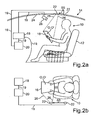
- the Fig. 2a and the Fig. 2b show the setting of the operating state of the lighting device 20 in response to the check signal generated by the control device 18 (S5). In the following, only the differences from the previous description of the figures will be discussed.
- the verification signal can be transmitted from the control device 18 to the illumination device 20.
- the lighting device 20 can set the operating state via a wired or wireless communication link 19 (S5), that is, for example, via said communication link 19, the at least one light source 22, which can be driven by a motor for example, on an exemplary rail at Roof can be moved or moved from the starting position to another position (S5, wherein the direction of movement of the at least one light source 22 in the Fig. 2a and 2b shown as an arrow).
- S5 wired or wireless communication link 19
- the at least one light source 22 which can be driven by a motor for example, on an exemplary rail at Roof can be moved or moved from the starting position to another position (S5, wherein the direction of movement of the at least one light source 22 in the Fig. 2a and 2b shown as an arrow).
- adjusting a position of the light source 22 adjusting a light intensity, a light color, a luminance of a Light field as a light source 22 and / or an angle of incidence of the at least one light source 22 done.
- the setting of the operating state (S5) of the lighting device 20 may additionally or alternatively comprise switching on and / or off and / or dimming the at least one light source 22.
- the light of the at least one light source 22 can be increased by 5 lux.
- an object 16 to be illuminated can be detected on, for example, a driver's seat and a corresponding at least one light source 22 can be adjusted such that the object 16 to be illuminated is optimally illuminated on a rear bench, if for example that too illuminating object, while the car 14 is in a traffic jam, is given back to a person in the backseat.
- the object 16 can be determined dynamically in the hands of the user 10 in the backseat and the corresponding illumination state can be adapted for the person 10 in the backseat.
- a profile can be used as an example, for example, that a user 10 could call for a business trip or a trip with business colleagues in the backseat.
- Such an exemplary profile may for example describe that for the seats in the back seat such a predetermined value of illuminance is stored for the object 16 to be illuminated, which is needed for an optimal reading situation.
- the corresponding motor vehicle 14 consequently increases the driving comfort and provides the respective user 10 with a situation-dependent or person-related, optimal lighting situation.
- the above-mentioned embodiments illustrate the principle of the method according to the invention and the lighting device 20 according to the invention, with the aid of a sensor device 28 and a control device 18, for example, to recognize where a body of the user 10 is currently located, and to determine the optimal illumination for a moment, for example to calculate. This takes place in real time, and preferably so, without user 10 noticing.
- the light or, for example, the intensity of light needed, for example, to read or write, is different from what you would expect, for example, when watching movies or when resting or looking out.
- an intention may be anticipated by the user 10. For example, if someone grabs the door interior with their hand and the vehicle 14 is stationary, a logical consequence would be for the user 10 to open the door.
- the exemplary door inner operator can be illuminated and / or accentuated as object 16 to be illuminated.
- This may, for example, work by, for example, detecting a gesture recognition the movement and position of the user 10 (for example, hands, arms, posture). Thereafter, a corresponding counter-reaction can be determined, for example calculated, and the lighting device 20 can be controlled and executed by the system, ie by the control device 18.
- This could, for example, be controlled by means of a menu of software of an infotainment system in order to produce the desired system response.
- the character of the system can be controlled, for example, to react very actively or to stand in the background.
Landscapes
- Engineering & Computer Science (AREA)
- Mechanical Engineering (AREA)
- Arrangements Of Lighting Devices For Vehicle Interiors, Mounting And Supporting Thereof, Circuits Therefore (AREA)
- Circuit Arrangement For Electric Light Sources In General (AREA)
Abstract
Die Erfindung betrifft ein Verfahren zum Betreiben einer Beleuchtungsvorrichtung (20) eines Kraftfahrzeugs (14), wobei eine Sensoreinrichtung (28) eine Position eines Körpers eines Benutzers (10) des Kraftfahrzeugs (14) ermittelt. Eine Steuereinrichtung (18) ermittelt anhand der ermittelten Position des Körpers ein zu beleuchtendes Objekt (16) und dessen Position innerhalb eines Innenraums des Kraftfahrzeugs (14). Es erfolgt ein Überprüfen eines Beleuchtungszustandes einer Oberfläche (O) des Objekts (16) durch Überprüfen, ob die Oberfläche (O) des Objekts (16) einen vorbestimmten Wert einer Beleuchtungsstärke aufweist. In Abhängigkeit von einem Überprüfungssignal der Steuereinrichtung (18), welches signalisiert, ob und/oder inwieweit die Beleuchtungsstärke der Oberfläche (O) den vorbestimmten Wert erreicht, wird ein Betriebszustand der Beleuchtungsvorrichtung (20), in welchem die Oberfläche (O) des Objekts (16) durch Beaufschlagen mit Licht durch die Beleuchtungsvorrichtung (20) die vorbestimmte Beleuchtungsstärke aufweist, eingestellt.The invention relates to a method for operating a lighting device (20) of a motor vehicle (14), wherein a sensor device (28) determines a position of a body of a user (10) of the motor vehicle (14). A control device (18) determines based on the determined position of the body to be illuminated object (16) and its position within an interior of the motor vehicle (14). A lighting condition of a surface (O) of the object (16) is checked by checking whether the surface (O) of the object (16) has a predetermined value of illuminance. Depending on a check signal of the control device (18), which signals whether and / or to what extent the illuminance of the surface (O) reaches the predetermined value, an operating state of the lighting device (20), in which the surface (O) of the object ( 16) by applying light through the lighting device (20) has the predetermined illuminance set.
Description
Die Erfindung betrifft ein Verfahren zum Betreiben einer Beleuchtungsvorrichtung eines Kraftfahrzeugs, bei dem eine Position eines Körpers eines Benutzers des Kraftfahrzeugs in einem Innenraum des Kraftfahrzeugs ermittelt wird und eine Steuereinrichtung einen Betriebszustand der Beleuchtungsvorrichtung einstellt.The invention relates to a method for operating a lighting device of a motor vehicle, wherein a position of a body of a user of the motor vehicle in an interior of the motor vehicle is determined and a control device sets an operating state of the lighting device.
Derzeitige Fahrzeugbeleuchtungssysteme für den Innenraum bestehen derzeit aus einem oder mehreren Lichtspots, die meistens am Dachhimmel angebracht sind, oder die eine in eine Zierleiste des Kraftfahrzeugs angebrachte Ambientebeleuchtung umfassen. Die Beleuchtungsvorrichtung umfasst dabei Lichtquellen aus Einzelteilen, die an unterschiedlichen Orten eingesetzt werden. Das Licht lässt sich jedoch bisher nur bedingt einstellen.Present interior vehicle lighting systems currently consist of one or more light spots, most of which are mounted on the headliner, or which include ambient lighting mounted in a trim strip of the motor vehicle. The lighting device comprises light sources from individual parts, which are used at different locations. However, the light can only be adjusted conditionally so far.
Aus der
Aus der
Werden Lichtspots als Lichtquelle in einer Beleuchtungsvorrichtung verwendet, so haben diese eine sehr beschränkte Leuchtfläche, sind jedoch hell. Ein Ambientelicht wird hauptsächlich nur als dekoratives Element zum Erzeugen einer vorbestimmten Stimmung benutzt. Im Stand der Technik ist das Licht jedoch stets an einen bestimmten Bewegungsrichtungsbereich gebunden und es kommt deshalb oft vor, dass ein Insasse dem Licht im Weg sitzt. Der Benutzer erzeugt somit einen Schatten, der meistens an einer Stelle erscheint oder er stört, oder es leuchtet nur dort, wo man kein Licht benötigt. Folglich muss ein Benutzer bisher in Kauf nehmen, dass ein Objekt, beispielsweise ein Buch oder ein Bedienelement des Kraftfahrzeugs, abgeschattet ist, oder er muss seine Körperhaltung an die Position des Lichtkegels anpassen.When light spots are used as a light source in a lighting device, they have a very limited luminous area but are bright. An ambient light is mainly used only as a decorative element for generating a predetermined mood. In the prior art that is However, light is always bound to a specific movement direction range and therefore it often happens that an occupant is sitting in the way of the light. The user thus creates a shadow that usually appears or interferes with a spot, or it only lights up where you do not need light. Consequently, a user must hitherto accept that an object, for example a book or a control element of the motor vehicle, is shaded, or he must adapt his posture to the position of the light cone.
Eine der Erfindung zugrundeliegende Aufgabe ist das Bereitstellen einer Beleuchtungsvorrichtung, die situations- oder benutzerabhängig eine optimale Ausleuchtung des Innenraums des Kraftfahrzeugs ermöglicht. Die Aufgabe wird von dem erfindungsgemäßen Verfahren zum Betreiben einer Beleuchtungsvorrichtung, der erfindungsgemäßen Beleuchtungsvorrichtung und dem erfindungsgemäßen Kraftfahrzeug gemäß den unabhängigen Patentansprüchen gelöst. Vorteilhafte Weiterbildungen der Erfindung sind durch die Unteransprüche gegeben.One object of the invention is to provide a lighting device that allows situation-dependent or user-dependent optimal illumination of the interior of the motor vehicle. The object is achieved by the method according to the invention for operating a lighting device, the lighting device according to the invention and the motor vehicle according to the invention according to the independent patent claims. Advantageous developments of the invention are given by the dependent claims.
Die Erfindung basiert auf der Idee, eine Beleuchtungsvorrichtung bereitzustellen, die dynamisch auf beispielsweise eine Körperbewegung oder eine Nutzungsabsicht des Benutzers reagiert. Hierzu wird mit einer Sensoreinrichtung des Kraftfahrzeugs eine Position des Körpers erfasst. Eine entsprechende Reaktion der Beleuchtungsvorrichtung wird in Abhängigkeit der Position des Körpers durch eine Steuereinrichtung ermittelt, die diese ansteuert und die Reaktion zur optimalen Ausleuchtung ausführt.The invention is based on the idea of providing a lighting device that reacts dynamically to, for example, a body movement or a user's intention to use. For this purpose, a position of the body is detected with a sensor device of the motor vehicle. A corresponding reaction of the lighting device is determined as a function of the position of the body by a control device, which controls it and carries out the reaction for optimal illumination.
Durch das erfindungsgemäße Verfahren und die erfindungsgemäße Beleuchtungsvorrichtung sowie ein entsprechend ausgestattetes Kraftfahrzeug kann das optimale Ausleuchten in Echtzeit stattfinden und zudem ohne, dass es der Benutzer bemerkt.The inventive method and the lighting device according to the invention and a correspondingly equipped motor vehicle optimal illumination can take place in real time and also without the user noticing.
Das erfindungsgemäße Verfahren dient entsprechend zum Betreiben einer Beleuchtungsvorrichtung eines Kraftfahrzeugs, also einer lichttechnischen Vorrichtung, vorzugsweise eine lichttechnische Vorrichtung zur Fahrzeuginnenbeleuchtung, die beispielsweise an einem Fahrzeugdach auf der Innenseite des Innenraums angeordnet sein kann. Eine Sensoreinrichtung, die vorzugsweise einen oder mehrere Sensoren, wie beispielsweise eine Kamera oder einen Ultraschallsensor, umfasst, ermittelt dabei eine Position des Körpers des Benutzers des Kraftfahrzeugs. Vorzugsweise ist die Sensoreinrichtung dabei in einem Innenraum des Kraftfahrzeugs angeordnet. Die Position des Körpers umfasst dabei beispielsweise eine Lage des Körpers, eine räumliche Körperposition oder eine Körperhaltung.The inventive method is used to operate a lighting device of a motor vehicle, ie a lighting device, preferably a lighting device for vehicle interior lighting, which may be arranged for example on a vehicle roof on the inside of the interior. A sensor device, which preferably comprises one or more sensors, such as a camera or an ultrasonic sensor, thereby determines a position of the body of the user of the motor vehicle. Preferably, the sensor device arranged in an interior of the motor vehicle. The position of the body includes, for example, a position of the body, a spatial body position or posture.
Die Sensoreinrichtung kann vorzugsweise eine berührungslose Sensoreinrichtung umfassen, also eine Einrichtung, die mindestens einen Sensor umfasst, der die Positionen des Körpers erfassen kann, ohne dass der Benutzer den mindestens einen Sensor berühren muss. Anhand der ermittelten Position des Körpers ermittelt eine Steuereinrichtung des Kraftfahrzeugs ein zu beleuchtendes Objekt und eine Position des Objekts innerhalb des Innenraum. Die Steuereinrichtung ist dabei eine Einrichtung, die eine Steuerelektronik umfasst, beispielsweise ein Mikrokontroller der Beleuchtungsvorrichtung oder ein Steuergerät des Kraftfahrzeugs. Das zu beleuchtende Objekt ist ein Objekt, das sich im Innenraum des Kraftfahrzeugs befindet und das gezielt von der Beleuchtungsvorrichtung beleuchtet werden soll. Es handelt sich dabei also um ein Zielobjekt. Das Objekt kann beispielsweise ein Buch umfassen, welches ein Benutzer im Innenraum lesen möchte, oder ein elektronisches Gerät, das der Benutzer benutzen möchte, also ein Nutzgegenstand des Benutzers.The sensor device may preferably comprise a non-contact sensor device, that is to say a device which comprises at least one sensor which can detect the positions of the body without the user having to touch the at least one sensor. Based on the determined position of the body determines a control device of the motor vehicle to be illuminated object and a position of the object within the interior. In this case, the control device is a device which comprises control electronics, for example a microcontroller of the lighting device or a control device of the motor vehicle. The object to be illuminated is an object which is located in the interior of the motor vehicle and which is intended to be illuminated by the lighting device. It is therefore a target object. For example, the object may include a book that a user wants to read in the interior, or an electronic device that the user wants to use, that is, a user's item of utility.
Die Steuereinrichtung überprüft einen Beleuchtungszustand einer Oberfläche des Objekts, beispielsweise eine aufgeschlagene Seite eines Buchs. Der Überprüfungsvorgang umfasst ein Überprüfen, ob die Oberfläche des Objekts einen vorbestimmten Wert einer Beleuchtungsstärke aufweist.The control device checks a lighting condition of a surface of the object, for example an opened page of a book. The verification process includes checking if the surface of the object has a predetermined value of illuminance.
Die Steuereinrichtung erzeugt ein Überprüfungssignal, vorzugsweise in Abhängigkeit eines Ergebnisses des Überprüfungsschrittes, welches signalisiert, ob und/oder inwieweit die Beleuchtungsstärke der Oberfläche den vorbestimmten Wert erreicht. Ein Signalisieren, ob die Beleuchtungsstärke der Oberfläche den vorbestimmten Wert erreicht, umfasst dabei eine qualitative Aussage, ob das Objekt beleuchtet ist oder nicht. Das Signalisieren, inwieweit die Beleuchtungsstärke der Oberfläche den vorbestimmten Wert erreicht, umfasst eine quantitative Aussage, die ein Abweichen oder eine Differenz des vorbestimmten Werts der Beleuchtungsstärke zu dem ermittelten tatsächlichen Wert der Beleuchtungsstärke, beispielweise um 5 Lux, angibt.The control device generates a check signal, preferably as a function of a result of the checking step, which signals whether and / or to what extent the illuminance of the surface reaches the predetermined value. Signaling whether the illuminance of the surface reaches the predetermined value includes a qualitative statement as to whether the object is illuminated or not. Signaling to what extent the illuminance of the surface reaches the predetermined value comprises a quantitative statement indicating a deviation or a difference of the predetermined value of the illuminance from the determined actual value of the illuminance, for example by 5 lux.
In Abhängigkeit von dem Überprüfungssignal erfolgt ein Einstellen eines Betriebszustandes der Beleuchtungsvorrichtung, in welchem die Oberfläche des Objekts durch Beaufschlagen mit Licht durch die Beleuchtungsvorrichtung die vorbestimmte Beleuchtungsstärke aufweist.In response to the check signal, an operating state of the lighting device in which the surface is set is set of the object by applying light through the lighting device has the predetermined illuminance.
Das erfindungsgemäße Verfahren ermöglicht ein optimales Ausleuchten in einer Vielzahl von Situationen, da die Position des Körpers des Benutzers nicht als Folge einer Bedienhandlung des Benutzers ermittelt wird, sondern jede geänderte Position des Benutzers automatisch erfasst und ermittelt wird und ein Überprüfungsvorgang für jede Änderung der Körperposition erfolgen kann. Das erfindungsgemäße Verfahren ermöglicht ebenfalls eine Echtzeitanpassung der Beleuchtungsverhältnisse im Innenraum. Dies hat direkt zur Folge, dass die Anpassung der Beleuchtung dynamisch, also stufenlos, benutzerspezifisch und situationsabhängig erfolgt, und dass der Benutzer das Einstellen des Betriebszustandes der Beleuchtungsvorrichtung kaum wahrnimmt und so durch das Einstellen der Beleuchtungssituation nicht gestört wird. Dadurch, dass stets eine optimale Ausleuchtung des zu beleuchtenden Objekts erfolgt, kann das zu beleuchtende Objekt so beleuchtet werden, dass es nicht durch einen körpereigenen Schatten des Benutzers verdeckt wird.The method according to the invention enables optimum illumination in a large number of situations, since the position of the user's body is not determined as a result of a user's action, but each changed position of the user is automatically detected and determined, and a checking process is carried out for each change of body position can. The inventive method also allows a real-time adjustment of the lighting conditions in the interior. This has the direct result that the adjustment of the lighting dynamically, ie continuously, user-specific and situation-dependent, and that the user hardly perceives the setting of the operating state of the lighting device and is thus not disturbed by adjusting the lighting situation. The fact that there is always an optimal illumination of the object to be illuminated, the object to be illuminated can be illuminated so that it is not obscured by the body's own shadow of the user.
Gemäß einer bevorzugten Ausführungsform des erfindungsgemäßen Verfahrens kann durch das Ermitteln der Positionen des Körpers eine Nutzungsabsicht des Benutzers erkannt werden. Damit kann vorhergesehen werden, welche Intention der Benutzer hat und auf sein Vorhaben kann die Beleuchtungsvorrichtung schnell reagieren. Beispielsweise kann hier ein Drehen des Körpers und/oder ein Greifen nach der Türinnenbetätigung erfasst und ermittelt und so die Absicht, die Tür zu öffnen, erkannt werden.According to a preferred embodiment of the method according to the invention can be detected by determining the positions of the body user's intention to use. Thus, it can be foreseen what intention the user has and his project, the lighting device can respond quickly. For example, here a rotation of the body and / or a gripping after the door inner operation can be detected and determined and so the intention to open the door can be detected.
Gemäß einer weiteren Ausführungsform des erfindungsgemäßen Verfahrenes umfasst das Überprüfen des Beleuchtungszustandes der Oberfläche des Objekts ein Ermitteln eines Ist-Werts der Beleuchtungsstärke, der beispielsweise durch eine Beleuchtungsstärkensensoreinrichtung erfasst wird, und ein Vergleichen des Ist-Werts mit einem beispielsweise in der Steuereinrichtung gespeicherten Soll-Wert der Beleuchtungsstärke. In Abhängigkeit von einem Unterschied des Ist-Werts zu dem Soll-Wert kann das Überprüfungs- signal erzeugt werden. Dies ermöglicht das Einstellen einer Toleranzgrenze oder einer Reaktionsträgheit der Beleuchtungsvorrichtung. Die Beleuchtungsvorrichtung kann so den Beleuchtungszustand nach personenspezifischen Bedürfnissen einstellen.According to a further embodiment of the method according to the invention, checking the illumination state of the surface of the object comprises determining an actual value of the illuminance, which is detected, for example, by an illuminance sensor device, and comparing the actual value with a desired value stored, for example, in the control device the illuminance. Depending on a difference of the actual value from the desired value, the check signal can be generated. This makes it possible to set a tolerance limit or a reaction inertia of the lighting device. The lighting device can thus adjust the lighting state according to person-specific needs.
Die Position des Körpers kann gemäß einer weiteren Ausführungsform des erfindungsgemäßen Verfahrens mit Hilfe einer Sensoreinrichtung ermittelt werden, die vorzugsweise ein Fahrerbeobachtungssystem, eine Kamera, eine Infrarotkamera, einen Pupillensensor, einen Näherungsschalter, einen Ultraschallsensor und/oder einen Drucksensor umfasst. Das Verwenden einer solchen beispielhaften Sensoreinrichtung ermöglicht eine besonders schnelle und zuverlässige Erfassung der Position des Körpers. Weiterhin kann ein bereits vorhandenes Kraftfahrzeugbauteil, das bereits im Innenraum des Kraftfahrzeugs vorhanden sind, genutzt werden, sodass ein nachträgliches Nachrüsten des Kraftfahrzeugs zumindest teilweise vermieden werden kann.The position of the body can be determined according to a further embodiment of the method according to the invention with the aid of a sensor device which preferably comprises a driver observation system, a camera, an infrared camera, a pupil sensor, a proximity switch, an ultrasonic sensor and / or a pressure sensor. The use of such an exemplary sensor device allows a particularly fast and reliable detection of the position of the body. Furthermore, an already existing motor vehicle component, which are already present in the interior of the motor vehicle, are used, so that a subsequent retrofitting of the motor vehicle can be at least partially avoided.
Mit Hilfe einer weiteren bevorzugten Ausführungsform des erfindungsgemäßen Verfahrens muss der Benutzer nicht unbedingt eine unbequeme Haltung einnehmen, um einen Schatten auf das zu beleuchtende Objekt zu vermeiden. Gemäß dieser Ausführungsform umfasst das Überprüfen des Beleuchtungszustandes der Oberfläche des Objekts ein Überprüfen dahingehend, ob der Körper des Benutzers wegen der ermittelten Position des Körpers und einer Position mindestens einer Lichtquelle der Beleuchtungsvorrichtung, beispielsweise einer punktförmigen Lichtquelle, relativ zu dem Körper des Benutzers die Oberfläche des Gegenstands ganz oder teilweise gegen die Lichtquelle abschirmt, abdunkelt oder abschattet.With the aid of a further preferred embodiment of the method according to the invention, the user does not necessarily have to assume an uncomfortable posture in order to avoid a shadow on the object to be illuminated. According to this embodiment, checking the lighting condition of the surface of the object comprises checking whether the user's body, due to the detected position of the body and a position of at least one light source of the lighting device, for example a point light source, relative to the user's body, is the surface of the user Part or all of the object shields against the light source, darkens or shades off.
Das Ermitteln des zu beleuchtenden Objekts kann gemäß einer weiteren Ausführungsform des erfindungsgemäßen Verfahrens ein Vorbestimmen des zu beleuchtenden Objekts umfassen. Durch beispielsweise Ermitteln einer Körpergeste oder Körperbewegung des Benutzers zum Vorbestimmen des zu beleuchtenden Objekts kann das zu beleuchtende Objekt anhand der Körpersprache des Benutzers, also aufgrund seiner Nutzungsabsicht, ermittelt werden. Durch ein alternatives oder zusätzliches Auswählen eines in der Steuereinrichtung gespeicherten benutzerspezifischen oder situationsabhängigen Profils wird ermöglicht, dass Vorlieben des Benutzers sowie personenspezifische Bedürfnisse berücksichtigt werden. Ein zusätzliches oder alternatives Erkennen einer Kontur und/oder eines Identifikationscodes des Objekts mithilfe der Sensoreinrichtung ermöglicht ein Ermitteln des zu beleuchtenden Objekts zum Vorbestimmen unabhängig von dem Benutzer, beispielsweise wenn ein Mobiltelefon von dem Beifahrersitz an einen Insassen auf der Rückbank weitergegeben wird, kann eine Beleuchtungssituation, die auf den Bereich des Beifahrers eingestellt war, für einen weiteren Benutzer auf der Rückbank eingestellt werden. Beispielsweise kann hierzu eine über eine drahtlose Kommunikationsverbindung übertragene Gerätenummer eines Mobiltelefons erkannt werden.The determination of the object to be illuminated may, according to a further embodiment of the method according to the invention, comprise a predetermination of the object to be illuminated. By, for example, determining a body gesture or body movement of the user for predetermining the object to be illuminated, the object to be illuminated can be determined on the basis of the body language of the user, that is, on the basis of his intention to use. By alternatively or additionally selecting a user-specific or situation-dependent profile stored in the control device, it is possible to take into account user preferences as well as person-specific needs. Additional or alternative detection of a contour and / or identification code of the object by means of the sensor device makes it possible to determine the object to be illuminated for predetermining independently of the user; for example, if a mobile telephone is passed from the front passenger seat to an occupant in the back seat, a lighting situation can occur , which was set to the area of the passenger, for another user on the Rear seat can be adjusted. For example, a device number of a mobile telephone transmitted via a wireless communication connection can be detected for this purpose.
Vorteilhafterweise ist die Steuereinrichtung dazu ausgelegt, eine Körpersprache oder personenbezogene Bedürfnisse des Benutzers zu lernen, indem gemäß einer weiteren Ausführungsform des erfindungsgemäßen Verfahrens ein Vorbestimmen des Werts der Beleuchtungsstärke durch eine Bedienhandlung des Benutzers und/oder anhand des in der Steuereinrichtung gespeicherten benutzerspezifischen oder situationsabhängigen Profils erfolgt. Eine Bedienhandlung des Benutzers umfasst beispielsweise eine Bediengeste, beispielsweise ein Winken mit der Hand, oder eine Sprachsteuerung, bei der der Benutzer beispielsweise durch den Befehl "Ich mag kein blaues Licht" vorbestimmen kann, dass gemäß dem entsprechenden benutzerspezifischen Profil ein Einstellen der Beleuchtungsvorrichtung, das kein Einstellen einer blauen Lichtfarbe vorsieht.The control device is advantageously designed to learn a body language or personal needs of the user by predetermining the value of the illuminance by an operator action of the user and / or by means of the user-specific or situation-dependent profile stored in the control device , An operator action of the user includes, for example, an operation gesture, such as a hand-waving, or a voice control in which the user can, for example, by the command "I like no blue light" predetermine that according to the corresponding user-specific profile setting the lighting device, the no adjustment of a blue light color provides.
Durch Identifizieren des Benutzers und/oder Erkennen eines Identifikationscodes des zu beleuchtenden Objekts kann gemäß einer weiteren Ausführungsform des erfindungsgemäßen Verfahrens eine unbewusste Steuerung des Beleuchtungszustandes durch den Benutzer erfolgen.By identifying the user and / or recognizing an identification code of the object to be illuminated, according to a further embodiment of the method according to the invention, an unconscious control of the illumination state can be carried out by the user.
Eine Beleuchtungsvorrichtung, die wenig Lichtquellen erfordert und damit einen geringeren Stromverbrauch sowie eine unkompliziertere Elektronik benötigt, wird durch das Einstellen des Betriebszustandes der Beleuchtungsvorrichtung begünstigt, das ein Bewegen mindestens einer Lichtquelle, vorzugsweise mindestens einer punktförmigen Lichtquelle, der Beleuchtungsvorrichtung umfassen kann. In dieser bevorzugten Ausführungsform des erfindungsgemäßen Verfahrens kann beispielsweise eine Lichtquelle, oder ein Lichtquellensystem mit mehreren punktförmigen Lichtquellen, bei einem Einstellen des Betriebszustandes beispielsweise auf einer Schiene am Dachhimmel entlang in eine andere Position relativ zu dem Benutzer verfahren oder bewegt werden und/oder beispielsweise in einer der Positionen gekippt werden, sodass sich zum Beispiel der Einstrahlwinkel der Lichtquelle ändert.A lighting device that requires little light sources and thus requires less power consumption and less complicated electronics is facilitated by adjusting the operating state of the lighting device, which may include moving at least one light source, preferably at least one point light source, the lighting device. In this preferred embodiment of the method according to the invention, for example, a light source, or a light source system with a plurality of punctiform light sources, moved in a setting of the operating state, for example on a rail on the headliner in a different position relative to the user or moved and / or for example in a the positions are tilted so that, for example, the angle of incidence of the light source changes.
Ein nahezu vollständiger Verzicht auf eine aufwendige Motorik in einer Beleuchtungsvorrichtung kann dagegen durch eine andere vorteilhafte Ausführungsform des erfindungsgemäßen Verfahrens erreicht werden, gemäß der ein Einstellen des Betriebszustandes der Beleuchtungsvorrichtung erfolgen kann, bei dem ein Ein- und/oder Ausschalten und/oder Dimmen der zumindest einen Lichtquelle der Beleuchtungsvorrichtung umfasst sein kann. Zusätzlich oder alternativ kann die zumindest eine Lichtquelle in ihrer Helligkeit verändert werden. Dies kann beispielsweise verwirklicht werden, indem beispielsweise verschiedene LEDs als Lichtquellen in einem beispielhaften LED-Himmel als Beleuchtungsvorrichtung in unterschiedlicher Art und Weise in ihrer Helligkeit eingestellt werden, also beispielsweise gedimmt werden. Alternativ kann beispielsweise eine Leuchtfläche als Lichtquelle partiell beleuchtet werden.An almost complete waiver of a complex motor in a lighting device, however, can be achieved by another advantageous embodiment of the method according to the invention, a setting of the operating state of the lighting device can, in which a switching on and / or off and / or dimming of the at least one light source of the lighting device can be included. Additionally or alternatively, the brightness of at least one light source can be changed. This can be achieved, for example, by setting different brightness levels in different manners as light sources in an exemplary LED sky as a lighting device, for example by dimming them for example. Alternatively, for example, a luminous area as a light source can be partially illuminated.
Das Einstellen des Betriebszustandes der Beleuchtungsvorrichtung kann gemäß eines bevorzugten Ausführungsbeispiels des erfindungsgemäßen Verfahrens das Einstellen einer Lichtstärke, einer Lichtfarbe, einer Leuchtdichte und/oder eines Einstrahlwinkels, der mindestens eine Lichtquelle umfassen. Dies ermöglicht eine fließende Änderung der Beleuchtungssituation, sodass der Insasse das Ändern der Beleuchtungssituation nicht mitbekommt und dadurch nicht gestört wird.The setting of the operating state of the lighting device, according to a preferred embodiment of the method according to the invention, the setting of a light intensity, a light color, a luminance and / or an angle of incidence comprising at least one light source. This allows a fluid change in the lighting situation, so that the occupant does not notice the changing of the lighting situation and is thus not disturbed.
Die obige Aufgabe wird ebenfalls gelöst durch eine erfindungsgemäße Beleuchtungsvorrichtung eines Kraftfahrzeugs, vorzugsweise eines Kraftwagens, die eine Steuereinrichtung umfasst, die dazu ausgelegt ist, die eine Steuereinrichtung betreffenden Verfahrensschritte einer der oben beschriebenen Ausführungsformen des erfindungsgemäßen Verfahrens durchzuführen. Vorzugsweise kann die Beleuchtungsvorrichtung mindestens eine punktförmige Lichtquelle, zum Beispiel eine Glühbirne oder einen Lichtspot, eine Leseleuchte, ein Leuchtfeld, ein Lichtband, einen LED-Lichthimmel, einen Lichtleiter und/oder eine OLED-Folie umfassen. Hierdurch werden das Einstellen verschiedenartiger Atmosphären und ein fließender Übergang der Beleuchtungssituation ermöglicht.The above object is likewise achieved by an illumination device according to the invention of a motor vehicle, preferably a motor vehicle, which comprises a control device which is designed to carry out the method steps relating to a control device of one of the above-described embodiments of the method according to the invention. Preferably, the lighting device may comprise at least one point light source, for example a light bulb or a light spot, a reading light, a light field, a light band, an LED light sky, a light guide and / or an OLED film. This makes it possible to set different atmospheres and a smooth transition of the lighting situation.
Die oben gestellte Aufgabe wird ebenfalls gelöst durch ein Kraftfahrzeug, vorzugsweise einen Kraftwagen, der eine Sensoreinrichtung umfasst und durch eine erfindungsgemäße Beleuchtungsvorrichtung gekennzeichnet ist.The above object is also achieved by a motor vehicle, preferably a motor vehicle, which comprises a sensor device and is characterized by a lighting device according to the invention.
Die Erfindung wird anhand der beigefügten Zeichnungen noch einmal durch konkrete Ausführungsbeispiele näher erläutert. Die gezeigten Beispiele stellen bevorzugte Ausführungsformen der Erfindung dar. Funktionsgleiche Elemente weisen in den Figuren dieselben Bezugszeichen auf. Es zeigt:
- Fig. 1a
- eine schematische Skizze zu einer Ausführungsform des erfindungsgemäßen Verfahrens in einer Seitenansicht,
- Fig. 1b
- eine schematische Skizze zu der Ausführungsform des erfindungsgemäßen Verfahrens gemäß der
Fig. 1a , jedoch in einer Aufsicht, - Fig. 2a
- eine schematische Skizze zu einer Ausführungsform des erfindungsgemäßen Verfahrens in einer Seitenansicht, und
- Fig. 2b
- eine schematische Skizze zu der
Fig. 2b , jedoch in Aufsicht.
- Fig. 1a
- a schematic sketch of an embodiment of the method according to the invention in a side view,
- Fig. 1b
- a schematic diagram of the embodiment of the inventive method according to the
Fig. 1a but in a supervision, - Fig. 2a
- a schematic sketch of an embodiment of the method according to the invention in a side view, and
- Fig. 2b
- a schematic sketch to the
Fig. 2b but in supervision.
Die
Im vorliegenden Beispiel der
Die
Die
Die Sensoreinrichtung 28 kann dazu ein Signal erzeugen, das die Bedienhandlung, Nutzungsabsicht oder Körpergeste und/oder die Position des Körperteils im Innenraum beschreibt. Anhand des Signals der Sensoreinrichtung 28 und anhand mindestens einer Abmessung des Innenraums des Kraftfahrzeugs kann so beispielsweise eine zu bedienende Vorrichtung des Kraftfahrzeugs 14 erfasst und/oder ermittelt werden. Durch eine solche räumliche Zuordnung kann zum Beispiel eine Handbewegung zur Betätigung des Fensterhebers von der gleichen Handbewegung zur Betätigung des Schiebedachs unterschieden werden.For this purpose, the
Vorzugsweise kann die Sensoreinrichtung 28 einen Ultraschallsensor umfassen, mit dessen Hilfe eine Distanzmessung über einen oder mehrere Messpunkte erfolgen kann, beispielsweise über drei oder vier Messpunkte, im Innenraum des Kraftfahrzeugs 14 erfasst werden kann. Damit kann zu jedem Zeitpunkt der Benutzung eine aktuelle Körperposition des Benutzers 10 erfasst und ermittelt werden.Preferably, the
Anhand der ermittelten Position des Körpers kann die Steuereinrichtung 18 ein Ermitteln des zu beleuchtenden Objekts 16 und dessen Position innerhalb des Innenraums des Kraftfahrzeugs 14 ermitteln (S2). Beispielsweise kann hierzu eine Software ein Ergebnis einer ermittelten Blickrichtung oder eines ermittelten Blickwinkels auswerten oder aber beispielsweise anhand der ermittelten Körperposition erkennen, ob und/oder was der Benutzer 10 beispielsweise etwas in der Hand hält. Alternativ kann beispielsweise die Steuereinrichtung 18 eine ermittelte Bedienhandlung oder Körpergeste auswerten und daraus eine Nutzungsabsicht, zum Beispiel ein beabsichtigtes Ergreifen eines Türinnenbetätigers, ermitteln.On the basis of the determined position of the body, the
Durch die Sensoreinrichtung 28 und/oder die Steuereinrichtung 18 kann das zu beleuchtende Objekt 16 mit Hilfe der Sensoreinrichtung 28 ermittelt werden, vorzugsweise durch Erkennen einer Kontur des Objekts 16 und/oder durch ein Erkennen eines Identifikationscodes des Objekts 16.By means of the
Die Steuereinrichtung 18 überprüft einen Beleuchtungszustand der Oberfläche O des Objekts 16. Dies kann beispielsweise durch Erfassen eines Werts einer Beleuchtungsstärke der Oberfläche erfolgen, zum Beispiel durch ein Luxmeter eines Beleuchtungsstärkensensors und durch Vergleichen der erfassten Beleuchtungsstärke mit einem Referenzwert. Eine solche beispielhafte Sensoreinrichtung 18 zum Erfassen einer Beleuchtungsstärke des zu beleuchtenden Objekts 16 kann beispielsweise an einer oder an verschiedenen Positionen in der Innenraumausstattung des Kraftfahrzeugs 14 angebracht sein. Alternativ kann beispielsweise, wenn das zu beleuchtende Objekt 16 beispielsweise ein mobiles Endgerät umfasst, das mobile Endgerät eine weitere Sensoreinrichtung 18 zum Erfassen der Beleuchtungsstärke umfassen. Weiterhin kann hierzu beispielsweise auch die gleiche Sensoreinrichtung 28, wie sie zum Erfassen der Position des Körpers verwendet wurde, beispielsweise als Kamera ausgestaltet, verwendet werden. Mit Hilfe beispielsweise eines entsprechenden Algorithmus erfolgt das Überprüfen des Beleuchtungszustandes der Oberfläche O des Objekts 16 durch Überprüfen, ob die Oberfläche O des Objekts 16 einen vorbestimmten Wert einer Beleuchtungsstärke aufweist.The
In der
Die Steuereinrichtung 18 erzeugt ein Überprüfungssignal (S4), welches im Beispiel der
Zusätzlich oder alternativ kann ein in der Steuereinrichtung 18 gespeichertes benutzerspezifisches oder situationsabhängiges Profils gespeichert und/oder aufgerufen werden. Der vorbestimmte Wert der Beleuchtungsstärke kann also beispielsweise vorprogrammiert sein oder während der Benutzung des Verfahrens von dem Benutzer 10 durch eine Bedienhandlung vorbestimmt werden, beispielsweise durch einen Sprachbefehl "Film schauen" oder "es ist mir zu hell", oder durch Bedienen eines Menüs eines Multi-Media-Interfaces.Additionally or alternatively, a user-specific or situation-dependent profile stored in the
Die
Das Überprüfungssignal kann von der Steuereinrichtung 18 an die Beleuchtungsvorrichtung 20 übertragen werden. In Abhängigkeit von dem Überprüfungssignal kann die Beleuchtungsvorrichtung 20 über eine drahtgebundene oder drahtlose Kommunikationsverbindung 19 den Betriebszustand einstellen (S5), also beispielsweise über die genannte Kommunikationsverbindung 19 die mindestens eine Lichtquelle 22, die beispielsweise von einem Motor angetrieben werden kann, auf einer beispielhaften Schiene am Dachhimmel von der Ausgangsposition in eine andere Position verfahren oder bewegt werden (S5, wobei die Bewegungsrichtung der mindestens einen Lichtquelle 22 in den
In einem weiteren, nicht in den Figuren dargestellten Ausführungsbeispiel kann beispielsweise ein zu beleuchtendes Objekt 16 auf beispielsweise einem Fahrersitz erfasst und eine entsprechende mindestens eine Lichtquelle 22 so eingestellt werden, dass das zu beleuchtende Objekt 16 optimal auf einer Rückbank ausgeleuchtet ist, wenn beispielsweise das zu beleuchtende Objekt, während der Kraftwagen 14 sich in einem Stau befindet, nach hinten zu einer Person auf der Rückbank gegeben wird. Dadurch kann das Objekt 16 dynamisch in den Händen des Benutzers 10 auf der Rückbank ermittelt und der entsprechende Beleuchtungszustand für die Person 10 auf der Rückbank angepasst werden. Als Beispiel für ein situationsabhängiges Profil kann als Beispiel ein Profil verwendet werden, dass ein Benutzer 10 bei beispielsweise einem Antritt einer Geschäftsreise oder einer Reise mit Geschäftskollegen auf der Rückbank aufrufen könnte. Ein solches beispielhaftes Profil kann beispielsweise beschreiben, dass für die Plätze auf der Rückbank ein solcher vorbestimmter Wert einer Beleuchtungsstärke für das zu beleuchtende Objekt 16 gespeichert ist, der für eine optimale Lesesituation benötigt wird. Das entsprechende Kraftfahrzeug 14 erhöht folglich den Fahrkomfort und stellt dem jeweiligen Benutzer 10 eine situationsabhängige oder personenbezogene, optimale Beleuchtungssituation zur Verfügung.In another exemplary embodiment, which is not shown in the figures, an
Die oben angeführten Ausführungsbeispiele veranschaulichen das Prinzip des erfindungsgemäßen Verfahrens und der erfindungsgemäßen Beleuchtungsvorrichtung 20, mit Hilfe einer Sensoreinrichtung 28 und einer Steuereinrichtung 18 beispielsweise zu erkennen, wo ein Körper des Benutzers 10 sich gerade befindet, und die für einen Moment optimale Ausleuchtung zu ermitteln, beispielsweise zu berechnen. Dies findet in Echtzeit statt und vorzugsweise so, ohne dass der Benutzer 10 es bemerkt. Das Licht oder beispielsweise die Lichtstärke, das man beispielsweise zum Lesen oder Schreiben braucht, ist ein anderes als das, was man beispielsweise beim Filmschauen oder beim Ausruhen oder Rausschauen erwarten würde.The above-mentioned embodiments illustrate the principle of the method according to the invention and the
Über ein Erkennen von Bewegungen hinaus kann beispielsweise eine Intention von dem Benutzer 10 vorhergesehen werden. Wenn beispielsweise jemand mit seiner Hand zur Türinnenbetätigung greift und das Fahrzeug 14 steht, wäre eine logische Folge beispielsweise, dass der Benutzer 10 die Tür aufmachen möchte. In diesem Fall kann mit Hilfe des erfindungsgemäßen Verfahrens der beispielhafte Türinnenbetätiger als zu beleuchtendes Objekt 16 angeleuchtet und/oder akzentuiert werden.In addition to detecting movement, for example, an intention may be anticipated by the
Dies kann beispielsweise funktionieren, indem beispielsweise eine Gestikerkennung die Bewegung und Position des Benutzers 10 (beispielsweise Hände, Arme, Körperhaltung) erfassen kann. Danach kann eine entsprechende Gegenreaktion ermittelt, zum Beispiel ausgerechnet, werden, und die Beleuchtungsvorrichtung 20 von dem System, also von der Steuereinrichtung 18, angesteuert und ausgeführt werden. Dies könnte beispielsweise mit Hilfe eines Menüs einer Software eines Infotainmentsystems gesteuert werden, um die gewünschte Systemreaktion hervorzurufen. Wie beispielsweise bei einer "Drive Select"-Funktion lässt sich so der Charakter des Systems steuern, ob es beispielsweise sehr aktiv reagieren oder eher im Hintergrund stehen soll.This may, for example, work by, for example, detecting a gesture recognition the movement and position of the user 10 (for example, hands, arms, posture). Thereafter, a corresponding counter-reaction can be determined, for example calculated, and the
Es ergeben sich unter anderem die Vorteile einer absolut optimalen Ausleuchtung in jeder Situation, das Vermindern von Schatten und das Beleuchten eines Objekts 16, wo man es braucht und/oder erwartet.Among other things, there are the benefits of having absolutely optimal illumination in every situation, reducing shadows and illuminating an
Claims (14)
umfassend die Schritte:
comprising the steps:
dadurch gekennzeichnet, dass
durch das Ermitteln der Position des Körpers eine Nutzungsabsicht des Benutzers (10) erkannt wird.Method according to claim 1,
characterized in that
by detecting the position of the body, a user's intention to use (10) is detected.
dadurch gekennzeichnet, dass
das Überprüfen des Beleuchtungszustandes der Oberfläche (O) des Objekts (16) ein Ermitteln eines Istwerts der Beleuchtungsstärke und ein Vergleichen des Istwerts mit einem Sollwert der Beleuchtungsstärke umfasst, und in Abhängigkeit von einem Unterschied des Istwerts zu dem Sollwert das Überprüfungssignal erzeugt wird.Method according to one of the preceding claims,
characterized in that
checking the lighting condition of the surface (O) of the object (16) comprises determining an actual value of illuminance and comparing the actual value with a setpoint illuminance, and generating the verify signal in response to a difference in the actual value from the setpoint.
dadurch gekennzeichnet, dass
die Position des Körpers mithilfe einer Sensoreinrichtung (20), die ein Fahrerbeobachtungssystem, eine Kamera, eine Infrarotkamera, einen Pupillensensor, einen Näherungsschalter, einen Ultraschallsensor und/oder einen Drucksensor umfasst, ermittelt wird.Method according to one of the preceding claims,
characterized in that
the position of the body by means of a sensor device (20) comprising a driver observation system, a camera, an infrared camera, a pupil sensor, a proximity switch, an ultrasonic sensor and / or a pressure sensor, is determined.
dadurch gekennzeichnet, dass
das Überprüfen des Beleuchtungszustandes der Oberfläche (O) des Objekts (16) ein Überprüfen dahingehend umfasst, ob der Körper des Benutzers (10) wegen der ermittelten Position des Körpers und einer Position mindestens einer Lichtquelle (22) der Beleuchtungsvorrichtung (20) relativ zu dem Körper des Benutzers (10) die Oberfläche (O) des Objekts (16) ganz oder teilweise gegen die mindestens eine Lichtquelle (22) abschirmt.Method according to one of the preceding claims,
characterized in that
checking the lighting condition of the surface (O) of the object (16) comprises checking whether the body of the user (10) is at least one light source (22) of the lighting device (20) relative to the determined location of the body and position Body of the user (10) the surface (O) of the object (16) completely or partially against the at least one light source (22) shields.
dadurch gekennzeichnet, dass das Ermitteln des zu beleuchtenden Objekts (16) umfasst:
characterized in that the determining of the object (16) to be illuminated comprises:
gekennzeichnet durch
marked by
gekennzeichnet durch
marked by
dadurch gekennzeichnet, dass
characterized in that
dadurch gekennzeichnet, dass
characterized in that
Applications Claiming Priority (1)
| Application Number | Priority Date | Filing Date | Title |
|---|---|---|---|
| DE102014009595.9A DE102014009595B4 (en) | 2014-06-27 | 2014-06-27 | Method for operating a lighting device of an interior of a motor vehicle |
Publications (2)
| Publication Number | Publication Date |
|---|---|
| EP2960111A1 true EP2960111A1 (en) | 2015-12-30 |
| EP2960111B1 EP2960111B1 (en) | 2018-06-13 |
Family
ID=53175229
Family Applications (1)
| Application Number | Title | Priority Date | Filing Date |
|---|---|---|---|
| EP15001076.7A Active EP2960111B1 (en) | 2014-06-27 | 2015-04-15 | Method for operating an illumination device of a passenger compartment of a motor vehicle and associated illumination device |
Country Status (2)
| Country | Link |
|---|---|
| EP (1) | EP2960111B1 (en) |
| DE (1) | DE102014009595B4 (en) |
Cited By (4)
| Publication number | Priority date | Publication date | Assignee | Title |
|---|---|---|---|---|
| DE102016215593A1 (en) | 2016-08-19 | 2018-02-22 | Volkswagen Aktiengesellschaft | System for illuminating an interior of a vehicle and method for operating the system |
| CN110621542A (en) * | 2017-05-30 | 2019-12-27 | 戴姆勒股份公司 | Lighting device for illuminating a vehicle interior of a motor vehicle |
| CN111137208A (en) * | 2019-12-20 | 2020-05-12 | 恒大新能源汽车科技(广东)有限公司 | Method, device and system for controlling illuminating lamp of storage box applied to automobile |
| WO2023083145A1 (en) * | 2021-11-12 | 2023-05-19 | 北京罗克维尔斯科技有限公司 | In-vehicle atmosphere lamp control method and apparatus, and storage medium |
Families Citing this family (5)
| Publication number | Priority date | Publication date | Assignee | Title |
|---|---|---|---|---|
| DE102016214477A1 (en) * | 2016-08-04 | 2018-02-08 | Bayerische Motoren Werke Aktiengesellschaft | Arrangement, means of transport and method for defining a color in a means of transportation |
| DE102017222167A1 (en) * | 2017-12-07 | 2019-06-13 | Bayerische Motoren Werke Aktiengesellschaft | Automated driving display device for displaying the active automated driving mode |
| DE102019210878A1 (en) * | 2019-07-23 | 2021-01-28 | Volkswagen Aktiengesellschaft | Lighting device for a motor vehicle for the directional lighting of a person, and method |
| DE102021209235A1 (en) | 2021-08-23 | 2023-02-23 | Brose Fahrzeugteile Se & Co. Kommanditgesellschaft, Bamberg | Method for functional control on a vehicle, taking into account the detected attention of a person in an interior of the vehicle |
| DE102021212231A1 (en) | 2021-10-29 | 2023-05-04 | Robert Bosch Gesellschaft mit beschränkter Haftung | Method for operating a vehicle with an interior monitoring device |
Citations (8)
| Publication number | Priority date | Publication date | Assignee | Title |
|---|---|---|---|---|
| DE29822554U1 (en) * | 1998-12-18 | 1999-03-18 | Leopold Kostal GmbH & Co. KG, 58507 Lüdenscheid | Lighting device for illuminating certain interior areas of a motor vehicle |
| DE10061039A1 (en) * | 2000-12-08 | 2002-06-13 | Daimler Chrysler Ag | Camera system for viewing dashboard instruments in road vehicle uses infrared charge coupled device picture camera aimed at dashboard |
| DE102005031637A1 (en) * | 2004-07-07 | 2006-02-16 | Denso Corp., Kariya | Lighting device for the passenger compartment of a vehicle |
| US7118239B2 (en) | 2003-10-01 | 2006-10-10 | Yachiyo Kogyo Kabushiki Kaisya | Sunroof panel apparatus for a vehicle |
| DE102006052777A1 (en) * | 2006-11-09 | 2008-05-15 | Bayerische Motoren Werke Ag | Ambiance lighting device for motor vehicle, has control device controlling light delivery over light source, and camera directed to vehicle interior to record section of interior in camera image, where device is adapted based on image |
| EP2390139A1 (en) * | 2010-05-31 | 2011-11-30 | Volvo Car Corporation | Interior lighting and illumination control |
| DE102012214108A1 (en) | 2011-10-11 | 2013-04-11 | Hyundai Motor Co. | ORGANIC ELECTROLUMINESCENCE LIGHTING DEVICE FOR A VEHICLE |
| DE102012015039A1 (en) * | 2012-07-28 | 2014-01-30 | Volkswagen Aktiengesellschaft | Interior lamp, particularly reading lamp for vehicle, particularly motor vehicle, has sensor device for detecting light intensity emitted from detected object, and control device for controlling radiation characteristic of lighting unit |
Family Cites Families (2)
| Publication number | Priority date | Publication date | Assignee | Title |
|---|---|---|---|---|
| SE529653C2 (en) * | 2005-09-06 | 2007-10-16 | Gm Global Tech Operations Inc | Systems and procedure for adaptive and self-learning control of vehicle lighting |
| DE102012017276B4 (en) * | 2012-08-31 | 2023-03-30 | Volkswagen Aktiengesellschaft | Method and device for automatically controlling a lighting unit in the interior of a vehicle |
-
2014
- 2014-06-27 DE DE102014009595.9A patent/DE102014009595B4/en not_active Expired - Fee Related
-
2015
- 2015-04-15 EP EP15001076.7A patent/EP2960111B1/en active Active
Patent Citations (8)
| Publication number | Priority date | Publication date | Assignee | Title |
|---|---|---|---|---|
| DE29822554U1 (en) * | 1998-12-18 | 1999-03-18 | Leopold Kostal GmbH & Co. KG, 58507 Lüdenscheid | Lighting device for illuminating certain interior areas of a motor vehicle |
| DE10061039A1 (en) * | 2000-12-08 | 2002-06-13 | Daimler Chrysler Ag | Camera system for viewing dashboard instruments in road vehicle uses infrared charge coupled device picture camera aimed at dashboard |
| US7118239B2 (en) | 2003-10-01 | 2006-10-10 | Yachiyo Kogyo Kabushiki Kaisya | Sunroof panel apparatus for a vehicle |
| DE102005031637A1 (en) * | 2004-07-07 | 2006-02-16 | Denso Corp., Kariya | Lighting device for the passenger compartment of a vehicle |
| DE102006052777A1 (en) * | 2006-11-09 | 2008-05-15 | Bayerische Motoren Werke Ag | Ambiance lighting device for motor vehicle, has control device controlling light delivery over light source, and camera directed to vehicle interior to record section of interior in camera image, where device is adapted based on image |
| EP2390139A1 (en) * | 2010-05-31 | 2011-11-30 | Volvo Car Corporation | Interior lighting and illumination control |
| DE102012214108A1 (en) | 2011-10-11 | 2013-04-11 | Hyundai Motor Co. | ORGANIC ELECTROLUMINESCENCE LIGHTING DEVICE FOR A VEHICLE |
| DE102012015039A1 (en) * | 2012-07-28 | 2014-01-30 | Volkswagen Aktiengesellschaft | Interior lamp, particularly reading lamp for vehicle, particularly motor vehicle, has sensor device for detecting light intensity emitted from detected object, and control device for controlling radiation characteristic of lighting unit |
Cited By (5)
| Publication number | Priority date | Publication date | Assignee | Title |
|---|---|---|---|---|
| DE102016215593A1 (en) | 2016-08-19 | 2018-02-22 | Volkswagen Aktiengesellschaft | System for illuminating an interior of a vehicle and method for operating the system |
| CN110621542A (en) * | 2017-05-30 | 2019-12-27 | 戴姆勒股份公司 | Lighting device for illuminating a vehicle interior of a motor vehicle |
| CN111137208A (en) * | 2019-12-20 | 2020-05-12 | 恒大新能源汽车科技(广东)有限公司 | Method, device and system for controlling illuminating lamp of storage box applied to automobile |
| CN111137208B (en) * | 2019-12-20 | 2021-08-13 | 恒大恒驰新能源汽车科技(广东)有限公司 | Method, device and system for controlling illuminating lamp of storage box applied to automobile |
| WO2023083145A1 (en) * | 2021-11-12 | 2023-05-19 | 北京罗克维尔斯科技有限公司 | In-vehicle atmosphere lamp control method and apparatus, and storage medium |
Also Published As
| Publication number | Publication date |
|---|---|
| EP2960111B1 (en) | 2018-06-13 |
| DE102014009595A1 (en) | 2015-12-31 |
| DE102014009595B4 (en) | 2016-10-20 |
Similar Documents
| Publication | Publication Date | Title |
|---|---|---|
| EP2960111B1 (en) | Method for operating an illumination device of a passenger compartment of a motor vehicle and associated illumination device | |
| EP2982541B1 (en) | Arrangement for creating ambient lighting for a vehicle and method for adjusting ambient lighting using the arrangement | |
| EP3386800B1 (en) | Method and system for controlling an interior lighting in a vehicle | |
| DE102015206953B4 (en) | Device and method for adapting an operating mode of an ambient light strip of a means of locomotion | |
| EP3484738B1 (en) | Vehicle having an operator control and display device and method for operating such a vehicle | |
| DE102012015039B4 (en) | Interior light for a vehicle | |
| EP3099547B1 (en) | Assembly module | |
| EP3126935B1 (en) | Pivotable internal mirror for a vehicle | |
| DE102016211494A1 (en) | Control device for a motor vehicle | |
| EP2673156A1 (en) | Method, device and computer program product for controlling a functional unit of a vehicle | |
| DE102013001086A1 (en) | A motor vehicle comprising a plurality of illumination means for illuminating the lateral or rearward vehicle surroundings | |
| DE102013223145B4 (en) | Vehicle with a device and method for illuminating an interior of the vehicle | |
| WO2014033042A1 (en) | Providing an input for an operating element | |
| WO2013152930A1 (en) | Method, device, and computer program product for controlling at least one function of at least one display device for a vehicle interior | |
| DE102017215809A1 (en) | Air outlet device for an interior of a motor vehicle and system | |
| DE102018005461B4 (en) | Device and method for controlling interior lighting | |
| DE102012024513A1 (en) | Environment illuminating device for vehicle, has adjusting device that is coupled with control device for adjustably illuminating the environment | |
| WO2015055308A1 (en) | Method for operating an illumination apparatus for an interior of a motor vehicle, and illumination apparatus | |
| DE102016211495A1 (en) | Control device for a motor vehicle | |
| DE202019106303U1 (en) | Driver surveillance camera for controlling lighting features | |
| DE102014213531A1 (en) | Function activation in vehicles | |
| EP3393842B1 (en) | Method and system for providing a user interface for at least one device of a vehicle | |
| DE102017212062A1 (en) | Lighting device for the interior of a motor vehicle | |
| WO2018099503A1 (en) | Device for adjusting the temperature of at least one surface as required | |
| EP3442312A1 (en) | Method for illuminating an interior of a motor vehicle, and motor vehicle |
Legal Events
| Date | Code | Title | Description |
|---|---|---|---|
| PUAI | Public reference made under article 153(3) epc to a published international application that has entered the european phase |
Free format text: ORIGINAL CODE: 0009012 |
|
| AK | Designated contracting states |
Kind code of ref document: A1 Designated state(s): AL AT BE BG CH CY CZ DE DK EE ES FI FR GB GR HR HU IE IS IT LI LT LU LV MC MK MT NL NO PL PT RO RS SE SI SK SM TR |
|
| AX | Request for extension of the european patent |
Extension state: BA ME |
|
| 17P | Request for examination filed |
Effective date: 20160630 |
|
| RBV | Designated contracting states (corrected) |
Designated state(s): AL AT BE BG CH CY CZ DE DK EE ES FI FR GB GR HR HU IE IS IT LI LT LU LV MC MK MT NL NO PL PT RO RS SE SI SK SM TR |
|
| REG | Reference to a national code |
Ref country code: DE Ref legal event code: R079 Ref document number: 502015004609 Country of ref document: DE Free format text: PREVIOUS MAIN CLASS: B60Q0003020000 Ipc: B60Q0003760000 |
|
| GRAP | Despatch of communication of intention to grant a patent |
Free format text: ORIGINAL CODE: EPIDOSNIGR1 |
|
| STAA | Information on the status of an ep patent application or granted ep patent |
Free format text: STATUS: GRANT OF PATENT IS INTENDED |
|
| RIC1 | Information provided on ipc code assigned before grant |
Ipc: B60Q 3/53 20170101ALN20180119BHEP Ipc: B60Q 3/76 20170101AFI20180119BHEP Ipc: B60Q 3/80 20170101ALI20180119BHEP |
|
| INTG | Intention to grant announced |
Effective date: 20180208 |
|
| GRAS | Grant fee paid |
Free format text: ORIGINAL CODE: EPIDOSNIGR3 |
|
| GRAA | (expected) grant |
Free format text: ORIGINAL CODE: 0009210 |
|
| STAA | Information on the status of an ep patent application or granted ep patent |
Free format text: STATUS: THE PATENT HAS BEEN GRANTED |
|
| AK | Designated contracting states |
Kind code of ref document: B1 Designated state(s): AL AT BE BG CH CY CZ DE DK EE ES FI FR GB GR HR HU IE IS IT LI LT LU LV MC MK MT NL NO PL PT RO RS SE SI SK SM TR |
|
| REG | Reference to a national code |
Ref country code: GB Ref legal event code: FG4D Free format text: NOT ENGLISH |
|
| REG | Reference to a national code |
Ref country code: CH Ref legal event code: EP Ref country code: AT Ref legal event code: REF Ref document number: 1008145 Country of ref document: AT Kind code of ref document: T Effective date: 20180615 |
|
| REG | Reference to a national code |
Ref country code: IE Ref legal event code: FG4D Free format text: LANGUAGE OF EP DOCUMENT: GERMAN |
|
| REG | Reference to a national code |
Ref country code: DE Ref legal event code: R096 Ref document number: 502015004609 Country of ref document: DE |
|
| REG | Reference to a national code |
Ref country code: NL Ref legal event code: MP Effective date: 20180613 |
|
| REG | Reference to a national code |
Ref country code: LT Ref legal event code: MG4D |
|
| PG25 | Lapsed in a contracting state [announced via postgrant information from national office to epo] |
Ref country code: NO Free format text: LAPSE BECAUSE OF FAILURE TO SUBMIT A TRANSLATION OF THE DESCRIPTION OR TO PAY THE FEE WITHIN THE PRESCRIBED TIME-LIMIT Effective date: 20180913 Ref country code: BG Free format text: LAPSE BECAUSE OF FAILURE TO SUBMIT A TRANSLATION OF THE DESCRIPTION OR TO PAY THE FEE WITHIN THE PRESCRIBED TIME-LIMIT Effective date: 20180913 Ref country code: FI Free format text: LAPSE BECAUSE OF FAILURE TO SUBMIT A TRANSLATION OF THE DESCRIPTION OR TO PAY THE FEE WITHIN THE PRESCRIBED TIME-LIMIT Effective date: 20180613 Ref country code: LT Free format text: LAPSE BECAUSE OF FAILURE TO SUBMIT A TRANSLATION OF THE DESCRIPTION OR TO PAY THE FEE WITHIN THE PRESCRIBED TIME-LIMIT Effective date: 20180613 Ref country code: SE Free format text: LAPSE BECAUSE OF FAILURE TO SUBMIT A TRANSLATION OF THE DESCRIPTION OR TO PAY THE FEE WITHIN THE PRESCRIBED TIME-LIMIT Effective date: 20180613 Ref country code: ES Free format text: LAPSE BECAUSE OF FAILURE TO SUBMIT A TRANSLATION OF THE DESCRIPTION OR TO PAY THE FEE WITHIN THE PRESCRIBED TIME-LIMIT Effective date: 20180613 Ref country code: CY Free format text: LAPSE BECAUSE OF FAILURE TO SUBMIT A TRANSLATION OF THE DESCRIPTION OR TO PAY THE FEE WITHIN THE PRESCRIBED TIME-LIMIT Effective date: 20180613 |
|
| PG25 | Lapsed in a contracting state [announced via postgrant information from national office to epo] |
Ref country code: RS Free format text: LAPSE BECAUSE OF FAILURE TO SUBMIT A TRANSLATION OF THE DESCRIPTION OR TO PAY THE FEE WITHIN THE PRESCRIBED TIME-LIMIT Effective date: 20180613 Ref country code: GR Free format text: LAPSE BECAUSE OF FAILURE TO SUBMIT A TRANSLATION OF THE DESCRIPTION OR TO PAY THE FEE WITHIN THE PRESCRIBED TIME-LIMIT Effective date: 20180914 Ref country code: HR Free format text: LAPSE BECAUSE OF FAILURE TO SUBMIT A TRANSLATION OF THE DESCRIPTION OR TO PAY THE FEE WITHIN THE PRESCRIBED TIME-LIMIT Effective date: 20180613 Ref country code: LV Free format text: LAPSE BECAUSE OF FAILURE TO SUBMIT A TRANSLATION OF THE DESCRIPTION OR TO PAY THE FEE WITHIN THE PRESCRIBED TIME-LIMIT Effective date: 20180613 |
|
| PG25 | Lapsed in a contracting state [announced via postgrant information from national office to epo] |
Ref country code: NL Free format text: LAPSE BECAUSE OF FAILURE TO SUBMIT A TRANSLATION OF THE DESCRIPTION OR TO PAY THE FEE WITHIN THE PRESCRIBED TIME-LIMIT Effective date: 20180613 |
|
| PG25 | Lapsed in a contracting state [announced via postgrant information from national office to epo] |
Ref country code: IS Free format text: LAPSE BECAUSE OF FAILURE TO SUBMIT A TRANSLATION OF THE DESCRIPTION OR TO PAY THE FEE WITHIN THE PRESCRIBED TIME-LIMIT Effective date: 20181013 Ref country code: EE Free format text: LAPSE BECAUSE OF FAILURE TO SUBMIT A TRANSLATION OF THE DESCRIPTION OR TO PAY THE FEE WITHIN THE PRESCRIBED TIME-LIMIT Effective date: 20180613 Ref country code: CZ Free format text: LAPSE BECAUSE OF FAILURE TO SUBMIT A TRANSLATION OF THE DESCRIPTION OR TO PAY THE FEE WITHIN THE PRESCRIBED TIME-LIMIT Effective date: 20180613 Ref country code: RO Free format text: LAPSE BECAUSE OF FAILURE TO SUBMIT A TRANSLATION OF THE DESCRIPTION OR TO PAY THE FEE WITHIN THE PRESCRIBED TIME-LIMIT Effective date: 20180613 Ref country code: SK Free format text: LAPSE BECAUSE OF FAILURE TO SUBMIT A TRANSLATION OF THE DESCRIPTION OR TO PAY THE FEE WITHIN THE PRESCRIBED TIME-LIMIT Effective date: 20180613 Ref country code: PL Free format text: LAPSE BECAUSE OF FAILURE TO SUBMIT A TRANSLATION OF THE DESCRIPTION OR TO PAY THE FEE WITHIN THE PRESCRIBED TIME-LIMIT Effective date: 20180613 |
|
| REG | Reference to a national code |
Ref country code: CH Ref legal event code: PK Free format text: BERICHTIGUNGEN |
|
| RIC2 | Information provided on ipc code assigned after grant |
Ipc: B60Q 3/80 20170101ALI20180119BHEP Ipc: B60Q 3/53 20170101ALN20180119BHEP Ipc: B60Q 3/76 20170101AFI20180119BHEP |
|
| PG25 | Lapsed in a contracting state [announced via postgrant information from national office to epo] |
Ref country code: SM Free format text: LAPSE BECAUSE OF FAILURE TO SUBMIT A TRANSLATION OF THE DESCRIPTION OR TO PAY THE FEE WITHIN THE PRESCRIBED TIME-LIMIT Effective date: 20180613 Ref country code: IT Free format text: LAPSE BECAUSE OF FAILURE TO SUBMIT A TRANSLATION OF THE DESCRIPTION OR TO PAY THE FEE WITHIN THE PRESCRIBED TIME-LIMIT Effective date: 20180613 |
|
| REG | Reference to a national code |
Ref country code: DE Ref legal event code: R097 Ref document number: 502015004609 Country of ref document: DE |
|
| PLBE | No opposition filed within time limit |
Free format text: ORIGINAL CODE: 0009261 |
|
| STAA | Information on the status of an ep patent application or granted ep patent |
Free format text: STATUS: NO OPPOSITION FILED WITHIN TIME LIMIT |
|
| 26N | No opposition filed |
Effective date: 20190314 |
|
| PG25 | Lapsed in a contracting state [announced via postgrant information from national office to epo] |
Ref country code: SI Free format text: LAPSE BECAUSE OF FAILURE TO SUBMIT A TRANSLATION OF THE DESCRIPTION OR TO PAY THE FEE WITHIN THE PRESCRIBED TIME-LIMIT Effective date: 20180613 Ref country code: DK Free format text: LAPSE BECAUSE OF FAILURE TO SUBMIT A TRANSLATION OF THE DESCRIPTION OR TO PAY THE FEE WITHIN THE PRESCRIBED TIME-LIMIT Effective date: 20180613 |
|
| PG25 | Lapsed in a contracting state [announced via postgrant information from national office to epo] |
Ref country code: AL Free format text: LAPSE BECAUSE OF FAILURE TO SUBMIT A TRANSLATION OF THE DESCRIPTION OR TO PAY THE FEE WITHIN THE PRESCRIBED TIME-LIMIT Effective date: 20180613 |
|
| REG | Reference to a national code |
Ref country code: CH Ref legal event code: PL |
|
| REG | Reference to a national code |
Ref country code: BE Ref legal event code: MM Effective date: 20190430 |
|
| PG25 | Lapsed in a contracting state [announced via postgrant information from national office to epo] |
Ref country code: LU Free format text: LAPSE BECAUSE OF NON-PAYMENT OF DUE FEES Effective date: 20190415 Ref country code: MC Free format text: LAPSE BECAUSE OF FAILURE TO SUBMIT A TRANSLATION OF THE DESCRIPTION OR TO PAY THE FEE WITHIN THE PRESCRIBED TIME-LIMIT Effective date: 20180613 |
|
| PG25 | Lapsed in a contracting state [announced via postgrant information from national office to epo] |
Ref country code: LI Free format text: LAPSE BECAUSE OF NON-PAYMENT OF DUE FEES Effective date: 20190430 Ref country code: CH Free format text: LAPSE BECAUSE OF NON-PAYMENT OF DUE FEES Effective date: 20190430 |
|
| PG25 | Lapsed in a contracting state [announced via postgrant information from national office to epo] |
Ref country code: BE Free format text: LAPSE BECAUSE OF NON-PAYMENT OF DUE FEES Effective date: 20190430 |
|
| PG25 | Lapsed in a contracting state [announced via postgrant information from national office to epo] |
Ref country code: TR Free format text: LAPSE BECAUSE OF FAILURE TO SUBMIT A TRANSLATION OF THE DESCRIPTION OR TO PAY THE FEE WITHIN THE PRESCRIBED TIME-LIMIT Effective date: 20180613 |
|
| PG25 | Lapsed in a contracting state [announced via postgrant information from national office to epo] |
Ref country code: IE Free format text: LAPSE BECAUSE OF NON-PAYMENT OF DUE FEES Effective date: 20190415 |
|
| PG25 | Lapsed in a contracting state [announced via postgrant information from national office to epo] |
Ref country code: PT Free format text: LAPSE BECAUSE OF FAILURE TO SUBMIT A TRANSLATION OF THE DESCRIPTION OR TO PAY THE FEE WITHIN THE PRESCRIBED TIME-LIMIT Effective date: 20181015 |
|
| REG | Reference to a national code |
Ref country code: AT Ref legal event code: MM01 Ref document number: 1008145 Country of ref document: AT Kind code of ref document: T Effective date: 20200415 |
|
| PG25 | Lapsed in a contracting state [announced via postgrant information from national office to epo] |
Ref country code: HU Free format text: LAPSE BECAUSE OF FAILURE TO SUBMIT A TRANSLATION OF THE DESCRIPTION OR TO PAY THE FEE WITHIN THE PRESCRIBED TIME-LIMIT; INVALID AB INITIO Effective date: 20150415 Ref country code: MT Free format text: LAPSE BECAUSE OF FAILURE TO SUBMIT A TRANSLATION OF THE DESCRIPTION OR TO PAY THE FEE WITHIN THE PRESCRIBED TIME-LIMIT Effective date: 20180613 |
|
| PG25 | Lapsed in a contracting state [announced via postgrant information from national office to epo] |
Ref country code: AT Free format text: LAPSE BECAUSE OF NON-PAYMENT OF DUE FEES Effective date: 20200415 |
|
| PG25 | Lapsed in a contracting state [announced via postgrant information from national office to epo] |
Ref country code: MK Free format text: LAPSE BECAUSE OF FAILURE TO SUBMIT A TRANSLATION OF THE DESCRIPTION OR TO PAY THE FEE WITHIN THE PRESCRIBED TIME-LIMIT Effective date: 20180613 |
|
| P01 | Opt-out of the competence of the unified patent court (upc) registered |
Effective date: 20230530 |
|
| PGFP | Annual fee paid to national office [announced via postgrant information from national office to epo] |
Ref country code: DE Payment date: 20230430 Year of fee payment: 9 |
|
| PGFP | Annual fee paid to national office [announced via postgrant information from national office to epo] |
Ref country code: GB Payment date: 20240423 Year of fee payment: 10 |
|
| PGFP | Annual fee paid to national office [announced via postgrant information from national office to epo] |
Ref country code: FR Payment date: 20240423 Year of fee payment: 10 |