EP2960100A2 - Servicerobotersystem - Google Patents
Servicerobotersystem Download PDFInfo
- Publication number
- EP2960100A2 EP2960100A2 EP15170834.4A EP15170834A EP2960100A2 EP 2960100 A2 EP2960100 A2 EP 2960100A2 EP 15170834 A EP15170834 A EP 15170834A EP 2960100 A2 EP2960100 A2 EP 2960100A2
- Authority
- EP
- European Patent Office
- Prior art keywords
- service robot
- base station
- contact charging
- unit
- flat contact
- Prior art date
- Legal status (The legal status is an assumption and is not a legal conclusion. Google has not performed a legal analysis and makes no representation as to the accuracy of the status listed.)
- Granted
Links
Images


Classifications
-
- G—PHYSICS
- G05—CONTROLLING; REGULATING
- G05D—SYSTEMS FOR CONTROLLING OR REGULATING NON-ELECTRIC VARIABLES
- G05D1/00—Control of position, course, altitude or attitude of land, water, air or space vehicles, e.g. using automatic pilots
- G05D1/02—Control of position or course in two dimensions
- G05D1/021—Control of position or course in two dimensions specially adapted to land vehicles
- G05D1/0212—Control of position or course in two dimensions specially adapted to land vehicles with means for defining a desired trajectory
- G05D1/0225—Control of position or course in two dimensions specially adapted to land vehicles with means for defining a desired trajectory involving docking at a fixed facility, e.g. base station or loading bay
-
- B—PERFORMING OPERATIONS; TRANSPORTING
- B60—VEHICLES IN GENERAL
- B60L—PROPULSION OF ELECTRICALLY-PROPELLED VEHICLES; SUPPLYING ELECTRIC POWER FOR AUXILIARY EQUIPMENT OF ELECTRICALLY-PROPELLED VEHICLES; ELECTRODYNAMIC BRAKE SYSTEMS FOR VEHICLES IN GENERAL; MAGNETIC SUSPENSION OR LEVITATION FOR VEHICLES; MONITORING OPERATING VARIABLES OF ELECTRICALLY-PROPELLED VEHICLES; ELECTRIC SAFETY DEVICES FOR ELECTRICALLY-PROPELLED VEHICLES
- B60L53/00—Methods of charging batteries, specially adapted for electric vehicles; Charging stations or on-board charging equipment therefor; Exchange of energy storage elements in electric vehicles
- B60L53/10—Methods of charging batteries, specially adapted for electric vehicles; Charging stations or on-board charging equipment therefor; Exchange of energy storage elements in electric vehicles characterised by the energy transfer between the charging station and the vehicle
- B60L53/14—Conductive energy transfer
- B60L53/16—Connectors, e.g. plugs or sockets, specially adapted for charging electric vehicles
-
- B—PERFORMING OPERATIONS; TRANSPORTING
- B60—VEHICLES IN GENERAL
- B60L—PROPULSION OF ELECTRICALLY-PROPELLED VEHICLES; SUPPLYING ELECTRIC POWER FOR AUXILIARY EQUIPMENT OF ELECTRICALLY-PROPELLED VEHICLES; ELECTRODYNAMIC BRAKE SYSTEMS FOR VEHICLES IN GENERAL; MAGNETIC SUSPENSION OR LEVITATION FOR VEHICLES; MONITORING OPERATING VARIABLES OF ELECTRICALLY-PROPELLED VEHICLES; ELECTRIC SAFETY DEVICES FOR ELECTRICALLY-PROPELLED VEHICLES
- B60L53/00—Methods of charging batteries, specially adapted for electric vehicles; Charging stations or on-board charging equipment therefor; Exchange of energy storage elements in electric vehicles
- B60L53/30—Constructional details of charging stations
- B60L53/35—Means for automatic or assisted adjustment of the relative position of charging devices and vehicles
- B60L53/36—Means for automatic or assisted adjustment of the relative position of charging devices and vehicles by positioning the vehicle
-
- H—ELECTRICITY
- H01—ELECTRIC ELEMENTS
- H01R—ELECTRICALLY-CONDUCTIVE CONNECTIONS; STRUCTURAL ASSOCIATIONS OF A PLURALITY OF MUTUALLY-INSULATED ELECTRICAL CONNECTING ELEMENTS; COUPLING DEVICES; CURRENT COLLECTORS
- H01R13/00—Details of coupling devices of the kinds covered by groups H01R12/70 or H01R24/00 - H01R33/00
- H01R13/62—Means for facilitating engagement or disengagement of coupling parts or for holding them in engagement
- H01R13/629—Additional means for facilitating engagement or disengagement of coupling parts, e.g. aligning or guiding means, levers, gas pressure electrical locking indicators, manufacturing tolerances
- H01R13/631—Additional means for facilitating engagement or disengagement of coupling parts, e.g. aligning or guiding means, levers, gas pressure electrical locking indicators, manufacturing tolerances for engagement only
- H01R13/6315—Additional means for facilitating engagement or disengagement of coupling parts, e.g. aligning or guiding means, levers, gas pressure electrical locking indicators, manufacturing tolerances for engagement only allowing relative movement between coupling parts, e.g. floating connection
-
- H—ELECTRICITY
- H01—ELECTRIC ELEMENTS
- H01R—ELECTRICALLY-CONDUCTIVE CONNECTIONS; STRUCTURAL ASSOCIATIONS OF A PLURALITY OF MUTUALLY-INSULATED ELECTRICAL CONNECTING ELEMENTS; COUPLING DEVICES; CURRENT COLLECTORS
- H01R2201/00—Connectors or connections adapted for particular applications
- H01R2201/26—Connectors or connections adapted for particular applications for vehicles
-
- Y—GENERAL TAGGING OF NEW TECHNOLOGICAL DEVELOPMENTS; GENERAL TAGGING OF CROSS-SECTIONAL TECHNOLOGIES SPANNING OVER SEVERAL SECTIONS OF THE IPC; TECHNICAL SUBJECTS COVERED BY FORMER USPC CROSS-REFERENCE ART COLLECTIONS [XRACs] AND DIGESTS
- Y02—TECHNOLOGIES OR APPLICATIONS FOR MITIGATION OR ADAPTATION AGAINST CLIMATE CHANGE
- Y02T—CLIMATE CHANGE MITIGATION TECHNOLOGIES RELATED TO TRANSPORTATION
- Y02T10/00—Road transport of goods or passengers
- Y02T10/60—Other road transportation technologies with climate change mitigation effect
- Y02T10/70—Energy storage systems for electromobility, e.g. batteries
-
- Y—GENERAL TAGGING OF NEW TECHNOLOGICAL DEVELOPMENTS; GENERAL TAGGING OF CROSS-SECTIONAL TECHNOLOGIES SPANNING OVER SEVERAL SECTIONS OF THE IPC; TECHNICAL SUBJECTS COVERED BY FORMER USPC CROSS-REFERENCE ART COLLECTIONS [XRACs] AND DIGESTS
- Y02—TECHNOLOGIES OR APPLICATIONS FOR MITIGATION OR ADAPTATION AGAINST CLIMATE CHANGE
- Y02T—CLIMATE CHANGE MITIGATION TECHNOLOGIES RELATED TO TRANSPORTATION
- Y02T10/00—Road transport of goods or passengers
- Y02T10/60—Other road transportation technologies with climate change mitigation effect
- Y02T10/7072—Electromobility specific charging systems or methods for batteries, ultracapacitors, supercapacitors or double-layer capacitors
-
- Y—GENERAL TAGGING OF NEW TECHNOLOGICAL DEVELOPMENTS; GENERAL TAGGING OF CROSS-SECTIONAL TECHNOLOGIES SPANNING OVER SEVERAL SECTIONS OF THE IPC; TECHNICAL SUBJECTS COVERED BY FORMER USPC CROSS-REFERENCE ART COLLECTIONS [XRACs] AND DIGESTS
- Y02—TECHNOLOGIES OR APPLICATIONS FOR MITIGATION OR ADAPTATION AGAINST CLIMATE CHANGE
- Y02T—CLIMATE CHANGE MITIGATION TECHNOLOGIES RELATED TO TRANSPORTATION
- Y02T90/00—Enabling technologies or technologies with a potential or indirect contribution to GHG emissions mitigation
- Y02T90/10—Technologies relating to charging of electric vehicles
- Y02T90/12—Electric charging stations
-
- Y—GENERAL TAGGING OF NEW TECHNOLOGICAL DEVELOPMENTS; GENERAL TAGGING OF CROSS-SECTIONAL TECHNOLOGIES SPANNING OVER SEVERAL SECTIONS OF THE IPC; TECHNICAL SUBJECTS COVERED BY FORMER USPC CROSS-REFERENCE ART COLLECTIONS [XRACs] AND DIGESTS
- Y02—TECHNOLOGIES OR APPLICATIONS FOR MITIGATION OR ADAPTATION AGAINST CLIMATE CHANGE
- Y02T—CLIMATE CHANGE MITIGATION TECHNOLOGIES RELATED TO TRANSPORTATION
- Y02T90/00—Enabling technologies or technologies with a potential or indirect contribution to GHG emissions mitigation
- Y02T90/10—Technologies relating to charging of electric vehicles
- Y02T90/14—Plug-in electric vehicles
Definitions
- Service robot systems in particular lawn mower systems, are already known which have a service robot having an energy storage unit, in particular an autonomous lawnmower, and a base station which is provided in at least one state for energy supply of the energy storage unit of the service robot.
- the service robot or the base station has at least two flat contact charging elements.
- the invention relates to a service robot system, in particular of a lawn mower system, with at least one service robot, in particular an autonomous lawn mower comprising at least one energy storage unit, and with at least one base station at least to a power supply of the energy storage unit in at least one state, wherein the service robot or the Base station has at least two flat contact charging elements.
- the at least two flat contact charging elements are provided for enabling a charge docking process of the service robot at the base station at least in an angular range of at least more than 15 °.
- the angle range extends in particular, starting from a longitudinal axis, in particular a symmetry longitudinal axis, at least one of the at least two flat contact charging elements, wherein in particular in each case 50% of the angular range extending from the longitudinal axis in two opposite directions.
- the at least two flat contact charging elements are preferably provided to allow a charge docking process of the service robot at the base station at least in an angular range of at least more than 30 ° and particularly preferably at least more than 40 °.
- the at least two flat contact charging elements are particularly preferably provided to allow a Ladeandock polish the service robot at the base station from different directions.
- the at least two flat contact charging elements are preferably provided to compensate for at least one offset, in particular an angular offset or a parallel offset, between the longitudinal axis of at least one of the at least two flat contact charging elements relative to at least one longitudinal axis of a mating contact unit or the base station during a charge docking process.
- offset in particular an angular offset or a parallel offset
- By “intended” is intended to be understood in particular specifically designed and / or specially equipped.
- the element and / or the unit fulfill / fulfill and / or execute this specific function in at least one application and / or operating state.
- a “dock docking process” is to be understood here in particular as meaning a process in which the service robot approaches the base station and the at least two flat contact charging elements supply energy to the energy storage unit with the mating contact unit, in particular with at least two mating contact elements of the mating contact unit, to transfer energy, in particular electrical energy transfer , are in contact.
- the service robot initiates the charge docking process automatically in a manner already known to a person skilled in the art, in particular as a result of a detection of a falling below of an energy storage limit value of the energy storage unit.
- a “flat contact charging element” is to be understood here in particular as a contact charging element which has a component thickness which is many times, in particular at least twice, preferably at least three times and more preferably at least four times smaller than an extension running transversely thereto , in particular a main extension, of the contact charging element. Particularly preferred is the component thickness along measured at least substantially parallel to a vertical axis of the base station or the service robot direction.
- “Substantially parallel” is to be understood here as meaning, in particular, an alignment of a direction relative to a reference direction, in particular in a plane, wherein the direction relative to the reference direction is a deviation, in particular less than 8 °, advantageously less than 5 ° and particularly advantageously less than 2 °.
- a main extension, in particular a largest surface extension, of the respective flat contact charging element particularly preferably extends in a plane which extends at least substantially perpendicular to the vertical axis of the base station or the service robot.
- the flat contact charging element (s) may have any cross-sectional shape that appears expedient to a person skilled in the art, such as, for example, a polygonal cross-sectional shape or a non-polygonal cross-sectional shape.
- the flat contact charging member (s) may have a round cross-sectional shape, a square cross-sectional shape, a triangular cross-sectional shape, a rectangular cross-sectional shape, an elliptical cross-sectional shape, an oval cross-sectional shape, or the like.
- the vertical axis of the service robot preferably runs at least substantially perpendicular to a base contact surface of the service robot, in particular a ground contact surface of a chassis unit of the service robot.
- the vertical axis of the base station preferably runs at least substantially perpendicular to a base support surface of the base station, in particular a base support surface of a base plate of the base station.
- substantially perpendicular is intended here to define, in particular, an orientation of a direction relative to a reference direction, the direction and the reference direction, in particular in one plane, including an angle of 90 ° and the angle a maximum deviation of, in particular, less than 8 °, advantageously less than 5 ° and particularly advantageously less than 2 °.
- the service robot is particularly preferably designed as an autonomous locomotion device.
- An "autonomous locomotion device” is to be understood here in particular as a device that automatically operates in an area and / or in an area an environment moves, oriented or automatically navigated, in particular moves itself automatically after a learning process in an area and / or in an environment and / or oriented.
- the term "autonomously move and / or orient” should here in particular define a locomotion, an orientation and / or a navigation of the autonomous locomotion device, in particular after a learning process, without human intervention.
- the service robot automatically moves in an area and / or in an environment after a learning process performed by an operator with the service robot, or orients itself automatically in an area and / or in an environment.
- the service robot can have any devices that appear meaningful to a person skilled in the art and already known to him, such as a GPS device, a compass device, a surround wire device, an optical device or the like.
- the service robot can do this be designed as an autonomous lawnmower, as an autonomous vacuum cleaner, as an autonomous sweeper, as an autonomous transport vehicle, as an autonomous aircraft, as an autonomous agricultural device o.
- the service robot is preferably in the form of an autonomous lawnmower, which is intended to remove and / or work on a working surface designed as a turf surface and / or a working environment designed as a garden environment.
- the service robot particularly preferably has a work surface processing unit designed as a mowing unit.
- the work surface processing unit can in this case by means of a drive unit of the service robot, which is provided at least for driving the chassis unit of the service robot, or by means of a separate mower drive unit, which is formed separately from the drive unit for driving the chassis unit driven.
- a load docking process of the service robot at the base station from different directions can be made possible.
- a high flexibility with regard to a charge docking process can advantageously be achieved.
- the active use of alternative access routes to protect the lawn or to achieve a short approach path when different sectors of the work area are processed in different time windows can be advantageously achieved by means of the inventive design.
- the load docking process of the service robot relative to a center axis of the base station relative to a central axis of the service robot in an angular range of at least ⁇ 7.5 ° is possible.
- the load docking process of the service robot relative to a center axis of the base station relative to a center axis of the service robot is made possible in an angle range of more than ⁇ 10 ° and particularly preferably more than ⁇ 15 °.
- the center axis of the base station particularly preferably extends at least substantially perpendicular to the vertical axis of the base station.
- the center axis of the service robot preferably runs at least substantially perpendicular to the vertical axis of the service robot.
- a loading docking process of the service robot at the base station in different angular sectors can be made possible.
- the at least two flat contact charging elements are arranged vertically offset from one another.
- the at least two flat contact charging elements viewed along a direction extending at least substantially parallel to the vertical axis of the service robot or the base station, are arranged vertically offset from one another.
- the at least two flat contact charging elements are arranged in two horizontal planes extending at least substantially parallel to one another. The horizontal planes in this case run at least substantially perpendicular to the vertical axis of the service robot or the base station.
- the at least two flat contact charging elements viewed along a direction extending at least substantially perpendicular to the vertical axis of the service robot or the base station, project at least over a partial area of the service robot or the base station.
- the at least two flat contact charging elements viewed in the respective horizontal plane, have a maximum transverse extent, which is smaller by a multiple than a maximum longitudinal extent.
- the at least two flat contact charging elements, viewed in the respective horizontal plane to have a polygonal configuration, a circular sector-like configuration, an elliptical-sector-like configuration or the like.
- the at least two flat contact charging elements viewed in the respective horizontal plane, have a circular configuration in which, in particular, a maximum transverse extension corresponds to a maximum longitudinal extension.
- the at least two flat contact charging elements viewed in a horizontal plane, are arranged one behind the other and are intended to receive a contact charging element with a circular cross section, such as a jack-type contact charging element.
- the at least two flat contact charging elements are at least substantially aligned with each other.
- the term "at least substantially aligned” is to be understood here to mean in particular an orientation of the at least two flat contact charging elements relative to one another, wherein at least two outer edges of the at least two flat contact charging elements, viewed along a direction extending at least substantially parallel to the vertical axis of the service robot or the base station, are arranged overlapping or, viewed along a direction extending at least substantially perpendicular to the vertical axis of the service robot or the base station, have a maximum offset of in particular less than 20 mm, preferably less than 15 mm and particularly preferably less than 10 mm.
- a compact arrangement of the at least two flat contact charging elements can be achieved.
- a reliable contact can be ensured, since the at least two flat contact charging elements can be brought reliably in contact with the mating contact unit at an oblique approach to contacting.
- the at least two flat contact charging elements are plate-like, disk-like or tongue-like.
- the at least two flat contact charging elements are preferably formed as flat components, which are at least substantially flat, at least in an unloaded state.
- the at least two flat contact charging elements may have another configuration that appears appropriate to a person skilled in the art.
- the at least two flat contact charging elements viewed in a plane extending at least substantially perpendicular to the vertical axis of the service robot or the base station, may have a polygonal configuration, a circular sector-like configuration, an elliptical sector-like configuration or the like.
- the service robot system comprises at least one mating contact unit which is provided for receiving at least one of the at least two flat contact charging elements and which is configured such that the load docking process of the service robot relative to the center axis of the base station to the central axis of the service robot in an angular range of at least ⁇ 7.5 ° is possible.
- the mating contact unit is designed such that the load docking process of the service robot relative to a center axis of the base station relative to a center axis of the service robot in an angular range of more than ⁇ 10 ° and more preferably greater than ⁇ 15 ° is possible.
- the service robot system comprises at least one mating contact unit which is provided for receiving at least one of the at least two flat contact charging elements and which has an insertion opening which has a minimum width extension which corresponds to at least three times a maximum width extension of one of the at least two flat contact charging elements ,
- the minimum width of the insertion opening preferably runs in a plane which extends at least substantially perpendicular to the vertical axis of the service robot or the base station.
- the base station preferably has the mating contact unit.
- the service robot preferably has the mating contact unit.
- the service robot system comprises at least one mating contact unit which has at least one mating contact element, which, viewed in a plane extending at least substantially perpendicular to the vertical axis of the service robot or the base station horizontal plane.
- the service robot system comprises at least one mating contact unit, which is provided for receiving at least one of the at least two flat contact charging elements, and which extends at least over an angular range of more than 30 °.
- an insertion opening of the mating contact unit extends over an angular range of more than 30 °, preferably over an angular range of more than 60 ° and particularly preferably over an angular range of more than 90 °.
- the service robot preferably has the mating contact unit, which extends over an angular range of more than 60 °, in particular on a front side of the service robot.
- the service robot viewed in a plane extending at least substantially perpendicular to the vertical axis of the service robot, preferably has a rounded front side, in particular a circular segment-like front side.
- the service robot system comprises at least one insulator element which is arranged between the at least two flat contact charging elements and at least partially bears against the at least two flat contact charging elements.
- the isolator element is preferably arranged, viewed along a direction extending at least substantially parallel to the vertical axis of the service robot or the base station, between the at least two flat contact charging elements.
- the at least two flat contact charging elements lie flat against the insulator element.
- the at least two flat contact charging elements rest only partially on the insulator element.
- advantageously a risk of short circuit due to contact of the at least two flat contact charging elements can be advantageously kept low.
- advantageously a high operator safety and a high product safety can be achieved.
- the insulator element extend beyond at least one of the at least two flat contact charging elements, at least along one direction.
- the insulator element preferably extends along at least one of the at least two flat contact charging elements along an at least substantially transversely, in particular perpendicular, direction to the vertical axis of the service robot or the base station.
- the insulator element preferably extends beyond both of the at least two flat contact charging elements at least along one direction.
- the at least two flat contact charging elements are mounted so as to be movable relative to one another.
- at least one of the at least two flat contact charging elements is movably mounted on the service robot or on the base station.
- the term "movably mounted” is intended here to define in particular a mounting of a unit and / or an element, wherein the unit and / or the element, in particular decoupled from an elastic deformation of the unit and / or the element, a movement possibility along at least a distance greater than 5 mm, preferably greater than 10 mm and particularly preferably greater than 20 mm and / or a possibility of movement about at least one axis by an angle greater than 15 °, preferably greater than 30 ° and more preferably greater than 45 °.
- At least one of the at least two flat contact charging elements is movably mounted relative to a housing of the service robot in an embodiment of the service robot with the at least two flat contact charging elements.
- at least one of the at least two flat contact charging elements is preferably mounted movably relative to a housing of the base station.
- at least one of the at least two flat contact charging elements is mounted in a translationally movable manner, for example along a direction extending at least substantially parallel to the vertical axis, or at least one of the at least two flat contact charging elements is pivotably mounted.
- a centering of the at least one of the at least two flat contact charging element can advantageously be achieved via at least one solid-state articulation, at least one spring tongue, by means of a guide unit and a tension or compression spring interacting therewith, or via another element which appears expedient to a person skilled in the art.
- an additional security function of the service robot can advantageously be made possible in a state of the service robot docked to the base station.
- an anti-theft function can be realized.
- the service robot system has at least one position holding unit which is provided to hold the service robot at least in a loading position relative to the base station.
- the position-holding unit can in this case be formed, for example, by at least one of the movably mounted flat contact charging elements or by both flat contact charging elements.
- the position holding unit is formed separately from the at least two flat contact charging elements, such as in an embodiment of the position holding unit as a magnetic holding unit, as a recess into which the service robot when starting the base station moves o. The like.
- the service robot system comprises at least one contact contact protection unit which has at least one movably mounted contact contact protection element which is provided to cover at least one of the at least two flat contact charging elements or at least one counter contact charging element of a counter contact charging unit in at least one state.
- the movably mounted contact-contact protection element it is conceivable for the movably mounted contact-contact protection element to be arranged directly on at least one of the at least two flat contact charging elements or for the contact-contact protection element to cover both flat contact charging elements in at least one state.
- the service robot system preferably additionally comprises at least one release unit, which is provided to release at least one maximum charging voltage in at least one charging position of the autonomous service robot relative to the base station as a function of at least one characteristic.
- the service robot and the base station may each comprise at least one communication unit which is provided for transmitting data, in particular electronic data or digital signals.
- the communication unit is preferably designed as a wireless communication unit.
- the communication unit may be configured as a WLAN communication unit, a Bluetooth communication unit, a radio communication unit, an RFID communication unit, an NFC unit, an infrared communication unit, a mobile radio network communication unit or the like.
- the communication unit is provided for bidirectional data transmission.
- a secure contact When contacting the at least two flat contact charging elements and the mating contact unit, a secure contact can be verified as a result of communication between the service robot and the base station. Thus, after a verification of a secure contact, a high charging voltage can be switched to the at least two flat contact charging elements and the mating contact unit.
- the communication between the service robot and the base station can here by means of a special additional electrical contacting, by means of the communication unit, by means of a magnetic coding, by means of a mechanical coding o.
- the service robot system comprises at least one data logger unit which is provided to log and evaluate at least one load parameter of at least two different service robots.
- a "data logger unit” is to be understood here in particular as a unit which at least receives data, in particular digital data, via an interface and stores it on a storage medium.
- the data logger unit may comprise a sensor unit.
- the data logger unit comprises, as an alternative or in addition to the sensor unit, at least one operating program which processes data and stores it in the storage medium.
- a service robot in particular an autonomous lawnmower, a service robot system according to the invention is proposed. It can be advantageously realized a service robot, by means of which advantageously a Ladeandockfrac from different directions is possible.
- the base station may in this case comprise a garden lamp unit, a motion detector unit and / or a weather station unit.
- a base station By means of the embodiment according to the invention can advantageously be realized a base station, by means of which advantageously a Ladeandockfrac from different directions is possible.
- the base station comprises at least one auxiliary fuel refueling unit which is provided to refuel at least one service robot in at least one state with at least one auxiliary substance.
- auxiliary fuel refueling unit is to be understood here as meaning, in particular, a unit which is provided to refuel the service robot with an auxiliary material designed as fertilizer, water or the like.
- the adjuvant refueling unit comprises at least one adjuvant supply tank, or the auxiliary fuel refueling unit is directly connected to an auxiliary material supply device such as a water pipe or the like.
- the service robot system according to the invention, the service robot according to the invention and / or the base station according to the invention should / should not be limited to the application and embodiment described above.
- the service robot system according to the invention, the service robot according to the invention and / or the base station according to the invention can have a number deviating from a number of individual elements, components and units specified herein for performing a function described herein.
- values lying within the stated limits are also to be disclosed as disclosed and used as desired.
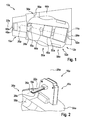
- FIG. 1 shows a service robot system 10a with at least one service robot 12a comprising at least one energy storage unit 14a, and at least one base station 16a at least to a power supply of the energy storage unit 14a in at least one state, wherein the service robot 12a or the base station 16a at least two flat contact charging elements 18a, 20a , In the in FIG. 1 illustrated embodiment, the base station 16a, the at least two flat contact charging elements 18a, 20a.
- the service robot system 10a is designed as a lawnmower system.
- the service robot 12a designed as an autonomous lawnmower.
- the service robot 12a comprises at least one drive unit 48a, at least the energy storage unit 14a at least to a power supply of the drive unit 48a and at least one control and / or regulating unit 50a at least to a control and / or regulation of the drive unit 48a.
- the drive unit 48a is in this case designed as an electric motor unit.
- the drive unit 48a it is also conceivable for the drive unit 48a to have another configuration which appears expedient to a person skilled in the art, for example a configuration as an internal combustion engine unit, as a hybrid motor unit or the like.
- the energy storage unit 14a is provided in addition to a power supply of the drive unit 48a to a power supply of other components of the service robot 12a.
- the energy storage unit 14a is in this case designed as an accumulator unit.
- the energy storage unit 14a it is also conceivable for the energy storage unit 14a to have another configuration that appears appropriate to a person skilled in the art, such as an embodiment as a wired power supply unit, as a fuel cell, as a fuel storage unit or the like.
- the service robot 12a further comprises at least one housing unit 52a, which at least the drive unit 48a, the energy storage unit 14a and the control and / or regulating unit 50a at least partially encloses.
- the service robot 12a comprises at least one chassis unit 54a.
- the chassis unit 54a has a configuration already known to a person skilled in the art.
- the chassis unit 54a may include steerable and / or non-steerable wheels that are driveable or unpowered.
- the chassis unit 54a in particular at least one drive wheel of the chassis unit 54a, can be driven by the drive unit 48a in a manner already known to a person skilled in the art.
- the service robot 12a may comprise at least one location location unit (not shown here in detail), which is provided for determining the position of the service robot 12a within a work area, in particular on a work surface.
- the location locating unit may be disposed on or in the housing unit 52a. In this case, the location location unit can be designed, for example, as a GPS unit.
- the location locating unit has another configuration that appears appropriate to a person skilled in the art, or that the service robot 12a is designed without a location locating unit and that it uses an inductive system Communication with a perimeter wire laid in the work area is autonomously moved and / or oriented in the work area.
- the service robot 12a is intended to move autonomously within the workspace or a work environment, in particular after a learning process, and to process a work surface, in particular a grass area, arranged in the work area or work environment automatically.
- the service robot 12a has a work surface processing unit 56a designed as a mowing unit.
- the work surface processing unit 56a has a configuration already known to a person skilled in the art.
- the work surface processing unit 56a designed as a mowing unit can have at least one cutting element, at least one mower drive unit and / or at least one crop collecting unit.
- the work surface processing unit 56a designed as a mowing unit can be driven by means of the drive unit 48a.
- a drive of the working surface processing unit 56a designed as a mowing unit by means of the drive unit 48a can be switched on or off as required.
- the drive unit 48a is provided in an operating mode of the service robot 12a to drive only the chassis unit 54a to move the service robot 12a.
- the drive unit 48a is provided to at least drive the chassis unit 54a and the work surface processing unit 56a designed as a mowing unit. Further operating modes that appear appropriate to a person skilled in the art for driving the chassis unit 54a and / or the work surface machining unit 56a designed as a mower unit by means of the drive unit 48a are also conceivable.
- the control and / or regulating unit 50a is also provided to initiate a start-up of the base station 16a of the service robot 12a upon detection of a low energy content of the energy storage unit 14a.
- the control and / or regulating unit 50a is provided to initiate a load docking process of the service robot 12a at the base station 16a, depending on an energy content of the energy storage unit 14a.
- the at least two flat contact charging elements 18a, 20a can be introduced into an insertion opening 30a of the mating contact unit 28a.
- the mating contact unit 28a is arranged on the service robot 12a.
- the mating contact unit 28a is arranged in an alternative embodiment of the service robot system 10a to the base station 16a and the at least two flat contact charging elements 18a, 20a are arranged on the base station 16a.
- the at least two flat contact charging elements 18a, 20a are provided to allow a charge docking process of the service robot 12a on the base station 16a at least in an angular range of at least more than 15 °.
- the at least two flat contact charging elements 18a, 20a are provided, in particular by means of cooperation with the at least two mating contact elements 32a, 34a, to allow a charge docking process of the service robot 12a to the base station 16a at least in an angular range of at least more than 15 °.
- the loading docking process of the service robot 12a is enabled relative to a center axis 22a of the base station 16a relative to a central axis 24a of the service robot 12a in an angular range of at least ⁇ 7.5 °.
- the at least two flat contact charging elements 18a, 20a project over at least one direction over an outer wall of a housing of the base station 16a.
- the at least two flat contact charging elements 18a, 20a project over an outer wall of the housing of the base station 16a along at least one substantially perpendicular to a vertical axis 26a of the base station 16a, in particular by at least more than 20 mm.
- the at least two flat contact charging elements 18a, 20a are picked up by the mating contact unit 28a during the docking process of the service robot 12a.
- the at least one mating contact unit 28a which is provided for receiving at least one of the at least two flat contact charging elements 18a, 20a, has the insertion opening 30a, which has a minimum width extension which corresponds to at least three times the maximum width extent of one of the at least two flat contact charging elements 18a, 20a ( FIGS. 1 and 3 ).
- FIG. 2 shows a detailed view of the at least two flat contact charging elements 18a, 20a of the base station 16a.
- the at least two flat contact charging elements 18a, 20a are arranged vertically offset from one another.
- the least two flat contact charging elements 18a, 20a viewed along a direction at least substantially parallel to the vertical axis 26a of the base station 16a extending direction, spaced relative to each other.
- the at least two flat contact charging elements 18a, 20a are tongue-like.
- the at least two flat contact charging elements 18a, 20a viewed in a plane extending at least substantially perpendicular to the vertical axis 26a of the base station 16a, have a longitudinal extent, in particular a longitudinal extent running at least substantially perpendicular to an outer wall surface of the base station 16a, which is many times greater , in particular at least a threefold, is greater than a width extension, in particular a width extending at least substantially parallel to the outer wall surface of the base station 16a.
- the at least two flat contact charging elements 18a, 20a viewed in a cross-sectional plane extending at least substantially parallel to the vertical axis 26a of the base station 16a, have a polygonal cross section, in particular a rectangular cross section.
- the at least two flat contact charging elements 18a, 20a have another cross-sectional shape which appears expedient to a person skilled in the art.
- the at least two flat contact charging elements 18a, 20a are arranged at least substantially in line with one another.
- a line extending at least substantially parallel to the vertical axis 26a of the base station 16a and extending from an outer edge of one of the at least two flat contact charging elements 18a, 20a in the direction of the further at least two flat contact charging elements 18a, 20a contacts one outer edge of the at least two flat contact charging elements 18a, 20a in at least one point.
- FIG. 3 shows a detailed view of the mating contact unit 28a, which is arranged according to the first embodiment of the service robot system 10a on the service robot 12a.
- the at least two mating contact elements 32a, 34a of the mating contact unit 28a are, viewed in a plane extending at least substantially perpendicular to the vertical axis 26a of the base station 16a, a horizontal plane.
- the at least two mating contact elements 32a, 34a are provided during a charging process to the at least two flat contact charging elements 18a, 20a to lie.
- the at least two mating contact elements 32a, 34a have, in order to enable a loading docking process of the service robot 12a on the base station 16a in an angular range of at least more than 15 ° along a direction extending at least substantially transversely to an insertion direction, a greatest areal extent.
- the insertion direction corresponds to a direction along which the at least two flat contact charging elements 18a, 20a can be introduced into the mating contact unit 28a.
- the at least two mating contact elements 32a, 34a are in this case designed as sheet metal contact elements, in particular as copper sheet contact elements. However, it is also conceivable for the at least two mating contact elements 32a, 34a to have another configuration which appears expedient to a person skilled in the art.
- the at least two mating contact elements 32a, 34a viewed along a direction extending at least substantially parallel to the vertical axis 26a of the base station 16a, are arranged on each inner side of the mating contact unit 28a.
- the at least two mating contact elements 32a, 34a viewed along the at least substantially parallel to the vertical axis 26a of the base station 16a extending direction, disposed on two opposite sides of the mating contact unit 28a.
- one of the at least two mating contact elements 32a, 34a is formed as a positive electrical pole and one of the at least two mating contact elements 32a, 34a is formed as a negative electrical pole.
- the at least two flat contact charging elements 18a, 20a can be inserted to produce an electrical contact between the at least two mating contact elements 32a, 34a ( Figures 2 and 4 ).
- the at least two flat contact charging elements 18a, 20a each contact only one of the at least two mating contact elements 32a, 34a on one side.
- the service robot system 10a has at least one insulator element 36a, which is arranged between the at least two flat contact charging elements 18a, 20a and at least partly bears against the at least two flat contact charging elements 18a, 20a ( Figures 2 and 4 ).
- the insulator element 36a extends at least along one direction beyond at least one of the at least two flat contact charging elements 18a, 20a. This extends the Insulator element 36a at least along a direction at least substantially perpendicular to the vertical axis 26a of the base station 16a direction over the at least two flat contact charging elements 18a, 20a addition.
- a contact of the at least two flat contact charging elements 18a, 20a with a rigid electrically conductive component can advantageously be avoided at least as far as possible.
- a risk of short circuit can be advantageously kept low.
- the service robot system 10a has at least one position holding unit 38a (FIG. FIG. 1 ), which is intended to hold the service robot 12a at least in a loading position relative to the base station 16a.
- the position holding unit 38a comprises at least one position holding element 58a (FIG. FIG. 1 ).
- the position-retaining element 58a is in this case formed as a recess, in particular as a depression, in a base plate 64a of the base station 16a, in which at least one wheel of the chassis unit 54a can be arranged in a loading position of the service robot 12a.
- the service robot 12a is durable at least in a loading position relative to the base station 16a, at least by means of a positive connection between at least one wheel of the chassis unit 54a and the bottom plate 64a of the base station 16a.
- the position holding member 58a another, a person skilled in the appear appropriate design, such as a configuration as a magnetic element (permanent or electromagnet), as a mechanical locking element o. The like.
- a correct height alignment of the at least two flat contact charging elements 18a, 20a relative to the at least two mating contact elements 32a, 34a can be achieved.
- the service robot 12a drives at least partially onto the bottom plate 64a of the base station 16a during a docking process.
- a correct height alignment of the at least two flat contact charging elements 18a, 20a relative to the at least two mating contact elements 32a, 34a is advantageously achievable even on an uneven ground on which the base station 16a can be arranged.
- the bottom plate 64a of the base station 16a may further comprise at least one sub-base fastener (not shown in detail herein), such as a spike or peg.
- a safer State of the base station 16a can be achieved. It can thus be advantageously at least largely avoided movement of the base station 16a, such as due to a driving of the bottom plate 64a of the base station 16a by the service robot 12a, relative to a substrate.
- a risk of tipping and / or a risk of rotation of the base station 16a can be kept low.
- the service robot system 10a can be operated with a safe voltage, for example by means of a protective extra-low voltage.
- a safe voltage is applied to the at least two flat contact charging elements 18a, 20a and / or to the at least two mating contact elements 32a, 34a only in a non-charging state and upon detection of a correct contacting of the at least two flat contact charging elements 18a, 20a and at least two mating contact elements 32a, 34a bears a higher charging voltage to the at least two flat contact charging elements 18a, 20a and to the at least two mating contact elements 32a, 34a.
- the detection of a correct contacting and / or a release of a charging voltage can here by means of an electrical communication, by means of a radio communication, such as RFID, NFC o. The like., By means of a magnetic coding, by means of an optical coding (camera, Sensor o. The like.), By means of a mechanical coding o. The like.
- the service robot system 10a has at least one data logger unit 44a (FIG. FIG. 1 ), which is intended to log and evaluate at least one load parameter of at least two different service robots 12a.
- the data logger unit 44a is designed to log at least one charge parameter, in particular a flowing current, during a charging process.
- the data logger unit 44a is arranged on the service robot 12a.
- the logged by means of the data logger 44a Charge parameters are transferable by means of a powerline communication via the at least two flat contact charging elements 18a, 20a and via the at least two mating contact elements 32a, 34a or by means of a communication unit, in particular a wireless communication unit, to the base station 16a or to an external readout device (not shown in detail here) ,
- a communication unit in particular a wireless communication unit
- the powerline communication it is conceivable that different service robots 12a different frequencies or codes can be assigned to differentiate. Thus, for example, it can advantageously be detected which service robot 12a consumes how much power.
- the base station 16a comprises at least one auxiliary fueling unit 46a, which is provided to refuel at least the service robot 12a in at least one state with at least one auxiliary substance.
- the auxiliary fuel filling unit 46a comprises at least one refueling element 60a which can be connected to a refueling nozzle 62a of the service robot 12a.
- the refueling nozzle 62a in this case has a funnel-shaped configuration.
- a maximum insertion opening width of the refueling nozzle 62a is at least three times greater than a maximum widthwise extent of the refueling member 60a.
- the auxiliary fueling unit 46a is arranged on one side of the base station 16a, which faces away from another side of the base station 16a on which the at least two flat contact charging elements 18a, 20a are arranged. However, it is also conceivable that the auxiliary fueling unit 46a is arranged on the further side of the base station 16a, on which the at least two flat contact charging elements 18a, 20a are arranged. Thus, in a state of the service robot 12a arranged at the base station 16a, a refueling of the service robot 12a with an auxiliary substance can take place and a simultaneous charging of the energy storage unit 14a can take place.
- FIGS. 5 to 13 Further embodiments of the invention are shown. The following descriptions and the drawings are essentially limited to the differences between the exemplary embodiments, with reference in principle to the same reference components, in particular with respect to components with the same reference numerals, to the drawings and / or the description of the other embodiments, in particular FIGS. 1 to 4 , can be referenced.
- To distinguish the embodiments of the letter a is the reference numerals of the embodiment in the FIGS. 1 to 4 readjusted.
- the letter a is replaced by the letters b to h.
- FIG. 5 shows a detailed view of an alternative embodiment of at least two flat contact charging elements 18b, 20b and a mating contact unit 28b of a service robot system 10b.
- the service robot system 10b on no physical insulator element, which is arranged between the at least two flat contact charging elements 18b, 20b.
- the at least two flat contact charging elements 18b, 20b when viewed along a direction extending at least substantially parallel to a vertical axis 26b of a base station 16b of the service robot system 10b, are arranged vertically offset from one another.
- an air gap is arranged between the at least two flat contact charging elements 18b, 20b.
- the at least two flat contact charging elements 18b, 20b viewed along the at least substantially parallel to the vertical axis 26b of the base station 16b extending direction, arranged relative to each other at a distance.
- the mating contact unit 28b has two contact receiving spaces for contacting the at least two flat contact charging elements 18b, 20b with mating contact elements 32b, 32b ', 34b, 34b' of the mating contact unit 28b, wherein at least one of the mating contact elements 32b, 32b ', 34b, 34b' in one of the Contact receiving rooms is arranged.
- the service robot system 10b are each arranged at least two mating contact elements 32b, 32b ', 34b, 34b' in one of the contact receiving spaces.
- at least two mating contact elements 32b, 32b ', 34b, 34b' has a positive electrical pole and a negative electrical pole of the mating contact unit 28b.
- one of the at least two flat contact charging elements 18b, 20b is arranged in a state in contact with the mating contact elements 32b, 32b ', 34b, 34b' between at least two of the mating contact elements 32b, 32b ', 34b, 34b'.
- at least partially shown service robot system 10b may be on the in FIGS. 1 to 4 shown service robot system 10a are referenced.
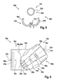
- FIG. 6 shows an alternative service robot system 10c with at least one service robot 12c comprising at least one energy storage unit 14c, and at least one base station 16c at least to a power supply of the energy storage unit 14c in at least one state, the service robot 12c or the base station 16c at least two flat contact charging elements 18c, 20c having.
- the at least two flat contact charging elements 18c, 20c are arranged vertically offset from one another.
- the at least two flat contact charging elements 18c, 20c are disc-shaped.
- the at least two flat contact charging elements 18c, 20c viewed in an at least substantially perpendicular to a vertical axis 26c of the base station 16c extending plane, an annular configuration.
- the at least two flat contact charging elements 18c, 20c extend along a circumferential direction extending around the vertical axis 26c of the base station 16c at least more than 50% of a total circumferential extent of a partial area of the base station 16c around the partial area of the base station 16c.
- the at least two flat contact charging elements 18c, 20c extend at least completely around the partial area of the base station 16c along the circumferential direction running around the vertical axis 26c of the base station 16c.
- the base station 16c in this case has a circular-cylindrical configuration.
- the service robot system 10c comprises at least one contact contact protection unit 40c, which has at least one movably mounted contact contact protection element 42c, which is provided, at least one of the at least two flat contact charging elements 18c, 20c in at least one Condition cover.
- the contact contact protection element 42c is movably mounted on the base station 16c.
- the contact contact protection element 42c is mounted in a translationally movable manner on the base station 16c, in particular along a direction extending at least substantially perpendicular to the vertical axis 26c of the base station 16c.
- Theêtberckenstoffschutzelement 42c has a hollow circular cylindrical configuration.
- the contact contact protection element 42c has at least one passage opening 66c, which is provided to enable and / or engage the at least two flat contact charging elements 18c, 20c through the contact contact protection element 42c as a result of a movement of the contact contact protection element 42c relative to the at least two flat contact charging elements 18c, 20c Extending the at least two flat contact charging elements 18c, 20c over the contact contact protection element 42c.
- the contact touch protection element 42c is movable at the base station 16c due to a charge docking process of the service robot 12c. In this case, the contact contact protection element 42c is translationally movable as a result of a direct contact of the service robot 12c and of the contact contact protection element 42c.
- the contact contact protection unit 40c may have at least one actuator element for a movement of the contact contact protection element 42c, wherein the actuator element moves the contact contact protection element 42c as a result of communication between the service robot 12c and the base station 16c.
- the contact contact protection unit 40c comprises at least one reset element 68c (FIG. FIG. 7 ), which is intended to automatically move the contact contact protection element 42c to a cover position, in particular after the service robot 12c has left its loading position.
- the at least two flat contact charging elements 18c, 20c are arranged completely within the contact-contact protection element 42c.
- the restoring element 68c is in this case designed as a spring-loaded centering cone which is movably mounted along a direction extending at least substantially parallel to the vertical axis 26c of the base station 16c, in particular mounted in a translationally movable manner.
- the restoring element 68c has another configuration and / or arrangement which appears expedient to a person skilled in the art.
- the restoring element 68c can also by means of a further actuator element of Kunststoffbertalkstofftechnikica 40c be acted upon, wherein the further actuator element is provided to limit or prevent a possibility of movement of the restoring element 68c and thus of Kunststoffberlickschutzelements 42c.
- the further actuator element only releases a movement possibility of the contact contact protection element 42c after the release of a release code from the service robot 12c to the base station 16c.
- an unauthorized charging process can be prevented.
- FIGS. 6 and 7 displayed service robot system 10c may on the in the FIGS. 1 to 4 shown service robot system 10a are referenced.
- FIG. 8 shows a detailed view of an alternative embodiment of at least two flat contact charging elements 18d, 20d and a mating contact unit 28d of a service robot system 10d.
- the service robot system 10d the at least two flat contact charging elements 18d, 20d, which are mounted relative to each other movable.
- the at least two flat contact charging elements 18d, 20d are connected to one another by means of at least one joint element 70d of the service robot system 10d.
- the at least two flat contact charging elements 18d, 20d have a semicircular ring-like configuration.
- the at least two flat contact charging elements 18d, 20d are provided to at least partially surround the mating contact unit 28d.
- the mating contact unit 28d has a circular-cylindrical configuration.
- the mating contact unit 28d which is provided for receiving at least one of the at least two flat contact charging elements 18d, 20d, extends over at least an angular range of more than 30 °.
- the mating contact unit 28d extends at least over an angular range of more than 180 °, preferably over an angular range of more than 270 ° and particularly preferably over an angular range of more than 300 °.
- the mating contact unit 28d is disposed on an outside of a base station 16d of the service robot system 10d.
- the base station 16d also has a circular cylindrical configuration.
- the service robot system 10d has at least one actuator element (not shown here in detail) for a movement of the at least two flat contact charging elements 18d, 20d relative to one another.
- a position holding unit 38d of the service robot system 10d will be realized.
- an anti-theft function can be realized, wherein the at least two flat contact charging elements 18d, 20d are again movable relative to each other after embracing the mating contact unit 28d, for example only after an input of a security code.
- FIG. 8 at least partially shown service robot system 10d may on the in the FIGS. 1 to 4 shown service robot system 10a are referenced.
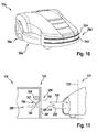
- FIG. 9 shows another alternative service robot system 10e with at least one service robot 12e comprising at least one energy storage unit 14e and with at least one base station 16e at least energy supply of the energy storage unit 14e in at least one state, wherein the service robot 12e or the base station 16e at least two flat contact charging elements 18e, 20e.
- the at least two flat contact charging elements 18e, 20e are plate-like.
- the at least two flat contact charging elements 18e, 20e viewed in a plane extending at least substantially perpendicular to a vertical axis 26e of the base station 16e, have an elliptical-sector-like configuration.
- an arcuate part of the at least two flat contact charging elements 18e, 20e, which are configured ellipsoid-like, is assigned to a longest side of the base station 16e.
- the base station 16e has, viewed in the at least substantially perpendicular to the vertical axis 26e of the base station 16e extending plane, a polygonal, in particular rectangular, configuration.
- the service robot system 10e may in this case comprise a contact contact protection unit (not shown here in greater detail), which has an at least substantially analogous configuration to that in FIG FIGS. 6 and 7 has shown Kunststoffbertstoffstofftechnikmaschine 40c.
- the Kunststoffberstoffschutzaku of in FIG. 9 shown service robotic system 10e has another, a professional appear appropriate design.
- the service robot 12e has a mating contact unit 28e for receiving and / or contacting the at least two flat contact charging elements 18e, 20e.
- the mating contact unit 28e has a plurality of mating contact elements 32e, 34e, which are arranged on a front side of the service robot 12e.
- the mating contact elements 32e, 34e are distributed uniformly at least over an angular range of more than 30 ° at the front of the service robot 12e.
- the mating contact elements 32e, 34e are arranged unevenly distributed at least over an angular range of more than 30 ° at the front of the service robot 12e.
- the mating contact unit 28e thus extends at least over an angular range of more than 30 ° on the service robot 12e.
- FIG. 10 shows a detailed view of the service robot 12e of in FIG. 9 shown service robot system 10e with an alternative embodiment of a mating contact unit 28e '.
- the mating contact unit 28e ' in this case comprises at least two mating contact elements 32e', 34e ', which are arranged in a circular arc on the service robot 12e, in particular on a front side of the service robot 12e.
- the at least two mating contact elements 32e ', 34e' extend at least over an angular range of more than 45 ° on the service robot 12e, in particular on a front side of the service robot 12e.
- the mating contact unit 28e ' forms slot-shaped receptacles for the at least two flat contact charging elements 18e, 20e.
- FIGS. 1 to 4 shown service robot system 10a are referenced.
- FIG. 11 shows another alternative service robot system 10f with at least one service robot 12f, which comprises at least one energy storage unit 14f, and at least one base station 16f at least for energy supply of the energy storage unit 14f in at least one state, wherein the service robot 12f or the base station 16f at least two flat contact charging elements 18f, 20f.
- the service robot 12f has the at least two flat contact charging elements 18f, 20f.
- the at least two flat contact charging elements 18f, 20f are formed like a tongue.
- the at least two flat contact charging elements 18f, 20f are mounted so as to be movable relative to one another.
- a movement axis of at least one of the at least two flat contact charging elements 18f, 20f in this case runs at least substantially perpendicular to a vertical axis 72f of the service robot 12f.
- the service robot system 10f comprises at least one position-holding unit 38f, which is provided to hold the service robot 12f at least in a loading position relative to the base station 16f.
- the position holding unit 38f comprises at least one latching element 74f for this purpose.
- the locking element 74f is designed as a latching hook.
- the latching element 74f is integrally formed with one of the at least two flat contact charging elements 18f, 20f, in particular with the movably mounted flat contact charging element 18f.
- the detent member 74f forms a position holding member 58f of the position holding unit 38f.
- the latching element 74f is arranged on a side remote from the service robot 12f on one of the at least two flat contact charging elements 18f, 20f.
- the latching element 74f is provided to cooperate with a corresponding to the latching element 74f counter-detent element 76f of the position holding unit 38f to hold the Serviceroboters 12f at least in a loading position relative to the base station 16f, in particular by means of a positive and / or non-positive connection.
- the counter-latching element 76f is arranged at the base station 16f for this purpose.
- the counter-latching element 76f is arranged on a mating contact element 32f of a mating contact unit 28f of the service robot system 10f.
- the latching element 74f can be brought into engagement with the counter-latching element 76f when contacting the at least two flat contact charging elements 18f, 20f with the mating contact unit 28f.
- the movably mounted flat contact charging element 18f is deflected upon insertion into an insertion opening 30f of the mating contact unit 28f as a result of an interaction of an inclined surface of the locking element 74f with the mating locking element 76f.
- the at least two flat contact charging elements 18f, 20f are moved into the mating contact unit 28f until the latching element 74f engages in the counter-latching element 76f.
- a movement of the service robot 12f in a direction away from the base station 16f direction is thus prevented as a result of engagement of the locking element 74f in the counter-locking element 76f.
- the movably mounted flat contact charging element 18f can be brought into contact with an unlocking element 78f of the position holding unit 38f.
- the movably mounted flat contact charging element 18f is again deflectable.
- the position holding unit 38f has at least one deflection retaining element 80f.
- the Auslenkhalteelement 80f may be formed here as an electromagnet or as a permanent magnet.
- the position holding unit 38f comprises at least one actuator element which is provided for automatically deflecting the movably mounted flat contact charging element 18f, in particular after a termination of a charging process.
- the actuator element can in this case be arranged on the service robot 12f or on the base station 16f.
- FIG. 11 shown service robot system 10f may on the in the FIGS. 1 to 4 shown service robot system 10a are referenced.
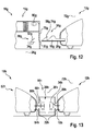
- FIG. 12 shows another alternative service robot system 10g with at least one service robot 12g, which includes at least one energy storage unit 14g, and at least one base station 16g at least to a power supply of the energy storage unit 14g in at least one state, wherein the service robot 12g or the base station 16g at least two flat contact charging elements 18g, 20g.
- the at least two flat contact charging elements 18g, 20g are formed like a tongue.
- the service robot system 10g comprises at least one position holding unit 38g, which is provided to hold the service robot 12g at least in a loading position relative to the base station 16g.
- the position holding unit 38g comprises at least one latching element 74g for this purpose.
- the locking element 74g is designed as a latching hook.
- the latching element 74g is integrally formed with one of the at least two flat contact charging elements 18g, 20g.
- forms the latching member 74g is a position holding member 58g of the position holding unit 38g.
- the latching element 74g is arranged on a side facing away from the service robot 12g on one of the at least two flat contact charging elements 18g, 20g.
- the latching element 74g is intended to cooperate with a corresponding to the latching element 74g formed counter-latching element 76g of the position holding unit 38g to hold the service robot 12g at least in a loading position relative to the base station 16g, in particular by means of a positive and / or non-positive connection.
- the counter-latching element 76g is arranged on the base station 16g for this purpose.
- the counter-latching element 76g is movably mounted on the base station 16g.
- the counter-latching element 76g is mounted in a translationally movable manner, in particular along a direction extending at least substantially parallel to a vertical axis 26g of the base station 16g.
- the counter-latching element 76g is in this case provided to cover an insertion opening 30g of a mating contact unit 28g at least to a large extent and / or to close it.
- the latching element 74g can be brought into engagement with the counter-latching element 76g when contacting the at least two flat contact charging elements 18g, 20g with the mating contact unit 28g.
- the at least two flat contact charging elements 18g, 20g are introduced into the mating contact unit 28g.
- the latching element 74g comprises at least one inclined surface for a movement of the counter-latching element 76g and for a release of the insertion opening 30g. The inclined surface moves the counter-latching element 76g due to an interaction of the inclined surface and the counter-latching element 76g in a direction extending at least substantially transversely to an insertion direction.
- the counter-latching element 76g is also acted upon by means of a spring element of the position-holding unit 38g in the direction of the latching element 74g with a force.
- the at least two flat contact charging elements 18g, 20g are moved into the mating contact unit 28g until a engagement of the counter-latching element 76g takes place in a latching recess of the latching element 74g, in particular due to a force of the spring element.
- a movement of the service robot 12g in a direction away from the base station 16g direction is thus prevented as a result of engagement of the counter-latching element 76g in the latching recess of the latching element 74g.
- the position-holding unit 38g has at least one deflection-holding element 80g.
- the Auslenkhalteelement 80g is formed here as an electromagnet. After a detection of a state of the at least two flat contact charging elements 18g, 20g which has moved completely out of the mating contact unit 28g, the deflection retaining element 80g releases the counter-locking element 76g again. The counter-latching element 76g is thus again movable by means of the spring element into an initial position.
- the position holding unit 38g comprises at least one actuator element which is provided to automatically deflect the counter-latching element 76g, in particular after a termination of a charging process.
- the actuator element may in this case be arranged on the service robot 12g or on the base station 16g.
- FIG. 12 shown service robot system 10g may on the in the FIGS. 1 to 4 shown service robot system 10a are referenced.
- FIG. 13 shows another alternative service robot system 10h with at least one service robot 12h, which comprises at least one energy storage unit 14h, and at least one base station 16h at least for energy supply of the energy storage unit 14h in at least one state, the service robot 12h or the base station 16h at least two flat contact charging elements 18h, 20h.
- the at least two flat contact charging elements 18h, 20h are tongue-like.
- the at least two flat contact charging elements 18h, 20h are provided for contacting at least two mating contact elements 32h, 34h of a mating contact unit 28h.
- the at least two mating contact elements 32h, 34h are arranged here at the base station 16h.
- the service robot system 10h comprises at least one further service robot 82h, which comprises at least two flat contact charging elements 84h, 86h.
- the at least two flat contact charging elements 84h, 86h of the further service robot 82h are provided to cooperate with at least one of the at least two mating contact elements 32h, 34h and at least one further mating contact element 88h of the mating contact unit 28h.
- the further mating contact element 88h is likewise arranged on the base station 16h.
- the further counter contact element 88h is designed as a positive electrical pole for the further service robot 82h.
- the mating contact element 32h which is provided for contacting with at least one flat contact charging element 84h of the further service robot 82h and with at least one flat contact charging element 18h of the service robot 12h, is designed as a negative electrical pole.
- the negative contact pole formed as a negative contact element 32h for the service robot 12h and the other service robot 82h is arranged in a plane.
- the mating contact element 34h which is designed as a positive electrical pole for at least one of the at least two flat contact charging elements 18h, 20h of the service robot 12h, is spaced, viewed along a direction at least substantially parallel to a vertical axis 26h of the base station 16h, relative to the further mating contact element 88h arranged.
- FIG. 13 shown service robot system 10h may on the in the FIGS. 1 to 4 shown service robot system 10a are referenced.
Landscapes
- Engineering & Computer Science (AREA)
- Power Engineering (AREA)
- Transportation (AREA)
- Mechanical Engineering (AREA)
- Aviation & Aerospace Engineering (AREA)
- Radar, Positioning & Navigation (AREA)
- Remote Sensing (AREA)
- Physics & Mathematics (AREA)
- General Physics & Mathematics (AREA)
- Automation & Control Theory (AREA)
- Manipulator (AREA)
- Electric Vacuum Cleaner (AREA)
- Charge And Discharge Circuits For Batteries Or The Like (AREA)
Description
- Es sind bereits Servicerobotersysteme, insbesondere Rasenmähersysteme, bekannt, die einen eine Energiespeichereinheit aufweisenden Serviceroboter, insbesondere einen autonomen Rasenmäher, und eine Basisstation aufweisen, die in zumindest einem Zustand zu einer Energiespeisung der Energiespeichereinheit des Serviceroboters vorgesehen ist. Hierzu weist der Serviceroboter oder die Basisstation zumindest zwei Flachkontaktladeelemente auf.
- Die Erfindung geht aus von einem Servicerobotersystem, insbesondere von einem Rasenmähersystem, mit zumindest einem Serviceroboter, insbesondere einem autonomen Rasenmäher, der zumindest eine Energiespeichereinheit umfasst, und mit zumindest einer Basisstation zumindest zu einer Energiespeisung der Energiespeichereinheit in zumindest einem Zustand, wobei der Serviceroboter oder die Basisstation zumindest zwei Flachkontaktladeelemente aufweist.
- Es wird vorgeschlagen, dass die zumindest zwei Flachkontaktladeelemente dazu vorgesehen sind, einen Ladeandockprozess des Serviceroboters an der Basisstation zumindest in einem Winkelbereich von zumindest mehr als 15° zu ermöglichen. Der Winkelbereich verläuft insbesondere ausgehend von einer Längsachse, insbesondere einer Symmetrielängsachse, zumindest eines der zumindest zwei Flachkontaktladeelemente, wobei sich insbesondere jeweils 50 % des Winkelbereichs ausgehend von der Längsachse in zwei entgegengesetzte Richtungen erstrecken. Bevorzugt sind die zumindest zwei Flachkontaktladeelemente dazu vorgesehen, einen Ladeandockprozess des Serviceroboters an der Basisstation zumindest in einem Winkelbereich von zumindest mehr als 30° und besonders bevorzugt von zumindest mehr als 40° zu ermöglichen. Somit sind die zumindest zwei Flachkontaktladeelemente besonders bevorzugt dazu vorgesehen, einen Ladeandockprozess des Serviceroboters an der Basisstation aus verschiedenen Richtungen zu ermöglichen. Vorzugsweise sind die zumindest zwei Flachkontaktladeelemente dazu vorgesehen, zumindest einen Versatz, insbesondere einen Winkelversatz oder einen parallelen Versatz, zwischen der Längsachse zumindest eines der zumindest zwei Flachkontaktladeelemente relativ zu zumindest einer Längsachse einer Gegenkontakteinheit oder der Basisstation, während eines Ladeandockprozesses auszugleichen. Unter "vorgesehen" soll insbesondere speziell ausgelegt und/oder speziell ausgestattet verstanden werden. Darunter, dass ein Element und/oder eine Einheit zu einer bestimmten Funktion vorgesehen ist, soll insbesondere verstanden werden, dass das Element und/oder die Einheit diese bestimmte Funktion in zumindest einem Anwendungs- und/oder Betriebszustand erfüllen/erfüllt und/oder ausführen/ausführt. Unter einem "Ladeandockprozess" soll hier insbesondere ein Prozess verstanden werden, bei dem der Serviceroboter die Basisstation anfährt und die zumindest zwei Flachkontaktladeelemente zu einer Energiespeisung der Energiespeichereinheit mit der Gegenkontakteinheit, insbesondere mit zumindest zwei Gegenkontaktelementen der Gegenkontakteinheit, zu einer Energieübertragung, insbesondere einer elektrischen Energieübertragung, in Kontakt bringbar sind. Der Serviceroboter leitet den Ladeandockprozess hierbei vorzugsweise auf eine, einem Fachmann bereits bekannte Art und Weise selbsttätig ein, insbesondere infolge einer Erkennung eines Unterschreitens eines Energiespeichergrenzwerts der Energiespeichereinheit.
- Unter einem "Flachkontaktladeelement" soll hier insbesondere ein Kontaktladeelement verstanden werden, das eine Bauteilstärke aufweist, die um ein Vielfaches, insbesondere um zumindest ein Zweifaches, bevorzugt um zumindest ein Dreifaches und besonders bevorzugt um zumindest ein Vierfaches, kleiner ist als eine quer dazu verlaufende Erstreckung, insbesondere eine Haupterstreckung, des Kontaktladeelements. Besonders bevorzugt wird die Bauteilstärke entlang einer zumindest im Wesentlichen parallel zu einer Hochachse der Basisstation oder des Serviceroboters verlaufenden Richtung gemessen. Unter "im Wesentlichen parallel" soll hier insbesondere eine Ausrichtung einer Richtung relativ zu einer Bezugsrichtung, insbesondere in einer Ebene, verstanden werden, wobei die Richtung gegenüber der Bezugsrichtung eine Abweichung insbesondere kleiner als 8°, vorteilhaft kleiner als 5° und besonders vorteilhaft kleiner als 2° aufweist.
- Eine Haupterstreckung, insbesondere eine größte Flächenerstreckung, des jeweiligen Flachkontaktladeelements verläuft besonders bevorzugt in einer Ebene, die sich zumindest im Wesentlichen senkrecht zur Hochachse der Basisstation oder des Serviceroboters erstreckt. Hierbei kann/können das/die Flachkontaktladeelement/e jegliche, einem Fachmann als sinnvoll erscheinende Querschnittsform aufweisen, wie beispielsweise eine polygonale Querschnittsform oder eine nichtpolygonale Querschnittsform. Somit kann/können das/die Flachkontaktladeelement/e eine runde Querschnittsform, eine quadratische Querschnittsform, eine dreieckige Querschnittsform, eine rechteckige Querschnittsform, eine elliptische Querschnittsform, eine ovale Querschnittsform o. dgl. aufweisen.
- Die Hochachse des Serviceroboters verläuft bevorzugt zumindest im Wesentlichen senkrecht zu einer Untergrundkontaktfläche des Serviceroboters, insbesondere einer Untergrundkontaktfläche einer Fahrwerkseinheit des Serviceroboters. Die Hochachse der Basisstation verläuft vorzugsweise zumindest im Wesentlichen senkrecht zu einer Untergrundstandfläche der Basisstation, insbesondere einer Untergrundstandfläche einer Bodenplatte der Basisstation. Der Ausdruck "im Wesentlichen senkrecht" soll hier insbesondere eine Ausrichtung einer Richtung relativ zu einer Bezugsrichtung definieren, wobei die Richtung und die Bezugsrichtung, insbesondere in einer Ebene betrachtet, einen Winkel von 90° einschließen und der Winkel eine maximale Abweichung von insbesondere kleiner als 8°, vorteilhaft kleiner als 5° und besonders vorteilhaft kleiner als 2° aufweist.
- Der Serviceroboter ist besonders bevorzugt als autonomes Fortbewegungsgerät ausgebildet. Unter einem "autonomen Fortbewegungsgerät" soll hier insbesondere ein Gerät verstanden werden, das sich selbsttätig in einem Bereich und/oder in einer Umgebung fortbewegt, orientiert oder selbsttätig navigiert, insbesondere sich nach einem Anlernprozess selbsttätig in einem Bereich und/oder in einer Umgebung fortbewegt und/oder orientiert. Der Ausdruck "sich selbsttätig fortbewegen und/oder orientieren" soll hier insbesondere eine Fortbewegung, eine Orientierung und/oder eine Navigation des autonomen Fortbewegungsgeräts, insbesondere nach einem Anlernprozess, ohne einen menschlichen Eingriff definieren. Vorzugsweise bewegt sich der Serviceroboter nach einem von einem Bediener mit dem Serviceroboter durchgeführten Anlernprozess selbsttätig in einem Bereich und/oder in einer Umgebung fort bzw. orientiert sich selbsttätig in einem Bereich und/oder in einer Umgebung. Zu einer selbsttätigen Fortbewegung, Orientierung und/oder Navigation kann der Serviceroboter jegliche, einem Fachmann als sinnvoll erscheinende und ihm bereits bekannte Vorrichtungen aufweisen, wie beispielsweise eine GPS-Vorrichtung, eine Kompassvorrichtung, eine Einfassungsdrahtvorrichtung, eine Optikvorrichtung o. dgl. Der Serviceroboter kann hierbei als autonomer Rasenmäher, als autonomer Staubsauger, als autonome Kehrmaschine, als autonomes Transportfahrzeug, als autonomes Fluggerät, als autonomes Agrargerät o. dgl. ausgebildet sein. Bevorzugt ist der Serviceroboter als autonomer Rasenmäher ausgebildet, der dazu vorgesehen ist, eine als Rasenfläche ausgebildete Arbeitsfläche und/oder eine als Gartenumgebung ausgebildete Arbeitsumgebung abzufahren und/oder zu bearbeiten. Hierzu weist der Serviceroboter besonders bevorzugt eine als Mähwerkeinheit ausgebildete Arbeitsflächenbearbeitungseinheit auf. Die Arbeitsflächenbearbeitungseinheit kann hierbei mittels einer Antriebseinheit des Serviceroboters, die zumindest zu einem Antrieb der Fahrwerkseinheit des Serviceroboters vorgesehen ist, oder mittels einer separaten Mähwerkantriebseinheit, die getrennt von der Antriebseinheit zum Antrieb der Fahrwerkseinheit ausgebildet ist, angetrieben werden.
- Mittels der erfindungsgemäßen Ausgestaltung des Servicerobotersystems kann vorteilhaft ein Ladeandockprozess des Serviceroboters an der Basisstation aus unterschiedlichen Richtungen ermöglicht werden. Somit kann vorteilhaft eine hohe Flexibilität hinsichtlich eines Ladeandockprozesses erreicht werden. Beispielsweise ist vorteilhaft ein alternativer Ladeandockprozess einleitbar, insbesondere ein entlang einer alternativen Anfahrtsrichtung durchführbarer alternativer Ladeandockprozess, wenn in einem ersten Ladeandockprozess erkannt wird, dass ein Anfahrtsweg durch einen Gegenstand, wie beispielsweise einen Ast o. dgl., versperrt ist. Auch die aktive Nutzung alternativer Anfahrtswege zu einer Schonung des Rasens oder um einen kurzen Anfahrtsweg zu erreichen, wenn verschiedene Sektoren des Arbeitsbereichs in unterschiedlichen Zeitfenstern bearbeitet werden, kann vorteilhaft mittels der erfindungsgemäßen Ausgestaltung erreicht werden. Zudem kann vorteilhaft ein häufiges Anfahren zu einer Kontaktierung der zumindest zwei Flachkontaktladeelemente mit der Gegenkontakteinheit während des Ladeandockprozesses vermieden werden, da eine geringe Präzision zu einer Kontaktierung nötig ist. Hierdurch kann eine Arbeitsfläche, insbesondere eine Grasfläche, vorteilhaft geschont werden.
- Besonders bevorzugt ist der Ladeandockprozess des Serviceroboters bezogen auf eine Zentrumsachse der Basisstation relativ zu einer Mittelachse des Serviceroboters in einem Winkelbereich von zumindest ± 7,5° ermöglichbar. Bevorzugt wird der Ladeandockprozess des Serviceroboters bezogen auf eine Zentrumsachse der Basisstation relativ zu einer Mittelachse des Serviceroboters in einem Winkelbereich von mehr als ± 10° und besonders bevorzugt von mehr als ± 15° ermöglicht. Hierbei verläuft die Zentrumsachse der Basisstation besonders bevorzugt zumindest im Wesentlichen senkrecht zur Hochachse der Basisstation. Die Mittelachse des Serviceroboters verläuft bevorzugt zumindest im Wesentlichen senkrecht zur Hochachse des Serviceroboters. Es kann vorteilhaft ein Ladeandockprozess des Serviceroboters an der Basisstation in unterschiedlichen Winkelsektoren ermöglicht werden.
- Des Weiteren wird vorgeschlagen, dass die zumindest zwei Flachkontaktladeelemente vertikal versetzt zueinander angeordnet sind. Bevorzugt sind die zumindest zwei Flachkontaktladeelemente, betrachtet entlang einer zumindest im Wesentlichen parallel zur Hochachse des Serviceroboters oder der Basisstation verlaufenden Richtung, vertikal versetzt zueinander angeordnet. Somit sind die zumindest zwei Flachkontaktladeelemente in zwei zumindest im Wesentlichen parallel zueinander verlaufenden Horizontalebenen angeordnet. Die Horizontalebenen verlaufen hierbei zumindest im Wesentlichen senkrecht zur Hochachse des Serviceroboters oder der Basisstation. Besonders bevorzugt ragen die zumindest zwei Flachkontaktladeelemente, betrachtet entlang einer zumindest im Wesentlichen senkrecht zur Hochachse des Serviceroboters oder der Basisstation verlaufenden Richtung, zumindest über einen Teilbereich des Serviceroboters oder der Basisstation hinaus. Vorzugsweise weisen die zumindest zwei Flachkontaktladeelemente, betrachtet in der jeweiligen Horizontalebene, eine maximale Quererstreckung auf, die um ein Vielfaches kleiner ist als eine maximale Längserstreckung. Hierbei ist es denkbar, dass die zumindest zwei Flachkontaktladeelemente, betrachtet in der jeweiligen Horizontalebene, eine polygonale Ausgestaltung, eine kreissektorartige Ausgestaltung, eine ellipsensektorartige Ausgestaltung o. dgl. aufweisen. In einer alternativen Ausgestaltung weisen die zumindest zwei Flachkontaktladeelemente, betrachtet in der jeweiligen Horizontalebene, eine kreisartige Ausgestaltung auf, bei der insbesondere eine maximale Quererstreckung einer maximalen Längserstreckung entspricht. Zudem ist es alternativ oder zusätzlich denkbar, dass die zumindest zwei Flachkontaktladeelemente, betrachtet in einer Horizontalebene, hintereinander angeordnet sind und dazu vorgesehen sind, ein Kontaktladeelement mit einem kreisförmigen Querschnitt, wie beispielsweise ein klinkensteckerartiges Kontaktladeelement aufzunehmen. Hierdurch kann vorteilhaft eine Fehlausrichtung des Serviceroboters relativ zur Basisstation um eine Längsrichtung des Serviceroboters ausgeglichen werden. Mittels der erfindungsgemäßen Ausgestaltung kann konstruktiv einfach ein Ladeandockprozess des Serviceroboters an der Basisstation aus unterschiedlichen Richtungen ermöglicht werden.
- Ferner wird vorgeschlagen, dass die zumindest zwei Flachkontaktladeelemente, betrachtet entlang einer Hochachse des Serviceroboters oder der Basisstation, insbesondere der Hochachse des Serviceroboters oder der Basisstation, zumindest im Wesentlichen fluchtend zueinander angeordnet sind. Unter "zumindest im Wesentlichen fluchtend" soll hier insbesondere eine Ausrichtung der zumindest zwei Flachkontaktladeelemente relativ zueinander verstanden werden, wobei zumindest zwei Außenkanten der zumindest zwei Flachkontaktladeelemente, betrachtet entlang einer zumindest im Wesentlichen parallel zur Hochachse des Serviceroboters oder der Basisstation verlaufenden Richtung, überdeckend angeordnet sind oder, betrachtet entlang einer zumindest im Wesentlichen senkrecht zur Hochachse des Serviceroboters oder der Basisstation verlaufenden Richtung, einen maximalen Versatz von insbesondere weniger als 20 mm, bevorzugt weniger als 15 mm und besonders bevorzugt weniger als 10 mm aufweisen. Mittels der erfindungsgemäßen Ausgestaltung kann vorteilhaft eine kompakte Anordnung der zumindest zwei Flachkontaktladeelemente erreicht werden. Zudem kann vorteilhaft eine zuverlässige Kontaktierung sichergestellt werden, da die zumindest zwei Flachkontaktladeelemente bei einer schrägen Anfahrt zur Kontaktierung zuverlässig in Kontakt mit der Gegenkontakteinheit bringbar sind.
- Zudem wird vorgeschlagen, dass die zumindest zwei Flachkontaktladeelemente plattenartig, scheibenartig oder zungenartig ausgebildet sind. Somit sind die zumindest zwei Flachkontaktladeelemente vorzugsweise als flächige Bauteile ausgebildet, die zumindest in einem unbelasteten Zustand zumindest im Wesentlichen eben sind. Es ist jedoch auch denkbar, dass die zumindest zwei Flachkontaktladeelemente eine andere, einem Fachmann als sinnvoll erscheinende Ausgestaltung aufweisen. Hierbei können die zumindest zwei Flachkontaktladeelemente, betrachtet in einer zumindest im Wesentlichen senkrecht zur Hochachse des Serviceroboters oder der Basisstation verlaufenden Ebene, eine polygonale Ausgestaltung, eine kreissektorartige Ausgestaltung, eine ellipsensektorartige Ausgestaltung o. dgl. aufweisen. Mittels der erfindungsgemäßen Ausgestaltung kann vorteilhaft eine große Kontaktfläche erreicht werden, mittels deren ein vorteilhafter Ladeandockprozess aus verschiedenen Richtungen realisierbar ist.
- Vorteilhafterweise umfasst das Servicerobotersystem zumindest eine Gegenkontakteinheit, die zu einer Aufnahme zumindest eines der zumindest zwei Flachkontaktladeelemente vorgesehen ist und die derart ausgestaltet ist, dass der Ladeandockprozess des Serviceroboters bezogen auf die Zentrumsachse der Basisstation zur Mittelachse des Serviceroboters in einem Winkelbereich von zumindest ± 7,5° ermöglichbar ist. Bevorzugt ist die Gegenkontakteinheit derart ausgebildet, dass der Ladeandockprozess des Serviceroboters bezogen auf eine Zentrumsachse der Basisstation relativ zu einer Mittelachse des Serviceroboters in einem Winkelbereich von mehr als ± 10° und besonders bevorzugt von mehr als ± 15° ermöglichbar ist.
- Des Weiteren wird vorgeschlagen, dass das Servicerobotersystem zumindest eine Gegenkontakteinheit umfasst, die zu einer Aufnahme zumindest eines der zumindest zwei Flachkontaktladeelemente vorgesehen ist und die eine Einführöffnung aufweist, die eine minimale Breitenerstreckung aufweist, die zumindest einem Dreifachen einer maximalen Breitenerstreckung eines der zumindest zwei Flachkontaktladeelemente entspricht. Die minimale Breitenerstreckung der Einführöffnung verläuft vorzugsweise in einer Ebene, die sich zumindest im Wesentlichen senkrecht zur Hochachse des Serviceroboters oder der Basisstation erstreckt. Bei einer Ausgestaltung des Serviceroboters mit den zumindest zwei Flachkontaktladeelementen weist vorzugsweise die Basisstation die Gegenkontakteinheit auf. Bei einer Ausgestaltung der Basisstation mit den zumindest zwei Flachkontaktladeelementen weist bevorzugt der Serviceroboter die Gegenkontakteinheit auf. Somit kann konstruktiv einfach eine Einführmöglichkeit der zumindest zwei Flachkontaktladeelemente in zumindest einem Winkelbereich von mehr als 15° erreicht werden. Es ist besonders vorteilhaft ein Versatz bei einem Ladeandockprozess ausgleichbar.
- Vorteilhafterweise umfasst das Servicerobotersystem zumindest eine Gegenkontakteinheit, die zumindest ein Gegenkontaktelement aufweist, das, betrachtet in einer zumindest im Wesentlichen senkrecht zur Hochachse des Serviceroboters oder der Basisstation verlaufenden Horizontalebene, flächig ausgebildet ist. Somit kann vorteilhaft eine große Kontaktierungsfläche bereitgestellt werden, die einen Ladeandockprozess aus unterschiedlichen Richtungen ermöglicht.
- Ferner wird vorgeschlagen, dass das Servicerobotersystem zumindest eine Gegenkontakteinheit umfasst, die zu einer Aufnahme zumindest eines der zumindest zwei Flachkontaktladeelemente vorgesehen ist, und die sich zumindest über einen Winkelbereich von mehr als 30° erstreckt. Insbesondere erstreckt sich eine Einführöffnung der Gegenkontakteinheit über einen Winkelbereich von mehr als 30°, bevorzugt über einen Winkelbereich von mehr als 60° und besonders bevorzugt über einen Winkelbereich von mehr als 90°. Bei einer Ausgestaltung der Basisstation mit den zumindest zwei Flachkontaktladeelementen weist bevorzugt der Serviceroboter die Gegenkontakteinheit auf, die sich über einen Winkelbereich von mehr als 60° erstreckt, insbesondere an einer Vorderseite des Serviceroboters. Hierzu weist der Serviceroboter, betrachtet in einer zumindest im Wesentlichen senkrecht zur Hochachse des Serviceroboters verlaufenden Ebene, vorzugsweise eine abgerundete Vorderseite auf, insbesondere eine kreissegmentartige Vorderseite. Mittels der erfindungsgemäßen Ausgestaltung kann eine besonders zuverlässige Kontaktierung der zumindest zwei Flachkontaktladeelemente mit der Gegenkontakteinheit über einen großen Winkelbereich erreicht werden.
- Zudem wird vorgeschlagen, dass das Servicerobotersystem zumindest ein Isolatorelement umfasst, das zwischen den zumindest zwei Flachkontaktladeelementen angeordnet ist und zumindest teilweise an den zumindest zwei Flachkontaktladeelementen anliegt. Hierbei ist das Isolatorelement vorzugsweise, betrachtet entlang einer zumindest im Wesentlichen parallel zur Hochachse des Serviceroboters oder der Basisstation verlaufenden Richtung, zwischen den zumindest zwei Flachkontaktladeelementen angeordnet. Bevorzugt liegen die zumindest zwei Flachkontaktladeelemente flächig am Isolatorelement an. Es ist jedoch auch denkbar, dass die zumindest zwei Flachkontaktladeelemente lediglich partiell am Isolatorelement anliegen. Somit kann vorteilhaft eine Kurzschlussgefahr infolge einer Berührung der zumindest zwei Flachkontaktladeelemente vorteilhaft gering gehalten werden. Somit können vorteilhaft eine hohe Bedienersicherheit und eine hohe Produktsicherheit erreicht werden.
- Des Weiteren wird vorgeschlagen, dass das Isolatorelement sich zumindest entlang einer Richtung über zumindest eines der zumindest zwei Flachkontaktladeelemente hinaus erstreckt. Hierbei erstreckt sich das Isolatorelement bevorzugt entlang einer zumindest im Wesentlichen quer, insbesondere senkrecht, zur Hochachse des Serviceroboters oder der Basisstation verlaufenden Richtung über zumindest eines der zumindest zwei Flachkontaktladeelemente hinaus. Vorzugsweise erstreckt sich das Isolatorelement zumindest entlang einer Richtung über beide der zumindest zwei Flachkontaktladeelemente hinaus. Somit kann vorteilhaft eine Kontaktüberbrückungsgefahr mittels eines metallischen Gegenstands gering gehalten werden, da der metallische Gegenstand vorteilhaft nur mit dem Isolatorelement und lediglich einem der zumindest zwei Flachkontaktladeelemente in Kontakt bringbar ist.
- Ferner wird vorgeschlagen, dass die zumindest zwei Flachkontaktladeelemente relativ zueinander beweglich gelagert sind. Hierbei ist vorzugsweise zumindest eines der zumindest zwei Flachkontaktladeelemente beweglich am Serviceroboter oder an der Basisstation gelagert. Der Ausdruck "beweglich gelagert" soll hier insbesondere eine Lagerung einer Einheit und/oder eines Elements definieren, wobei die Einheit und/oder das Element, insbesondere entkoppelt von einer elastischen Verformung der Einheit und/oder des Elements, eine Bewegungsmöglichkeit entlang zumindest einer Strecke größer als 5 mm, bevorzugt größer als 10 mm und besonders bevorzugt größer als 20 mm aufweist und/oder eine Bewegungsmöglichkeit um zumindest eine Achse um einen Winkel größer als 15°, bevorzugt größer als 30° und besonders bevorzugt größer als 45° aufweist. Hierbei ist vorzugsweise zumindest eines der zumindest zwei Flachkontaktladeelemente bei einer Ausgestaltung des Serviceroboters mit den zumindest zwei Flachkontaktladeelementen relativ zu einem Gehäuse des Serviceroboters beweglich gelagert. Bei einer Ausgestaltung der Basisstation mit den zumindest zwei Flachkontaktladeelementen ist bevorzugt zumindest eines der zumindest zwei Flachkontaktladeelemente relativ zu einem Gehäuse der Basisstation beweglich gelagert. Ferner ist es auch denkbar, dass zumindest eines der zumindest zwei Flachkontaktladeelemente translatorisch beweglich gelagert ist, wie beispielsweise entlang einer zumindest im Wesentlichen parallel zur Hochachse verlaufenden Richtung, oder zumindest eines der zumindest zwei Flachkontaktladeelemente schwenkbar gelagert ist. Eine Zentrierung des zumindest einen der zumindest zwei Flachkontaktladeelement kann hierbei vorteilhaft über zumindest ein Festkörpergelenke, zumindest eine Federzunge, mittels einer Führungseinheit und einer damit zusammenwirkenden Zug- oder Druckfeder, oder über ein anderes, einem Fachmann als sinnvoll erscheinendes Element erreicht werden. Mittels der erfindungsgemäßen Ausgestaltung kann vorteilhaft eine zusätzliche Sicherungsfunktion des Serviceroboters in einem an der Basisstation angedockten Zustand des Serviceroboters ermöglicht werden. Zudem kann vorteilhaft eine Diebstahlsicherungsfunktion realisiert werden.
- Zudem wird vorgeschlagen, dass das Servicerobotersystem zumindest eine Positionshalteeinheit aufweist, die dazu vorgesehen ist, den Serviceroboter zumindest in einer Ladeposition relativ zur Basisstation zu halten. Die Positionshalteeinheit kann hierbei beispielsweise von zumindest einem der beweglich gelagerten Flachkontaktladeelemente oder von beiden Flachkontaktladeelemente gebildet werden. Es ist jedoch auch denkbar, dass die Positionshalteeinheit separat von den zumindest zwei Flachkontaktladeelementen ausgebildet ist, wie beispielsweise bei einer Ausgestaltung der Positionshalteeinheit als magnetische Halteeinheit, als Vertiefung, in die der Serviceroboter bei einem Anfahren der Basisstation hineinfährt o. dgl. Mittels der erfindungsgemäßen Ausgestaltung kann vorteilhaft eine sichere Positionierung des Serviceroboters in einer Ladeposition relativ zur Basisstation erreicht werden.
- Des Weiteren wird vorgeschlagen, dass das Servicerobotersystem zumindest eine Kontaktberührschutzeinheit umfasst, die zumindest ein beweglich gelagertes Kontaktberührschutzelement aufweist, das dazu vorgesehen ist, zumindest eines der zumindest zwei Flachkontaktladeelemente oder zumindest ein Gegenkontaktladeelement einer Gegenkontaktladeeinheit in zumindest einem Zustand abzudecken. Hierbei ist es denkbar, dass das beweglich gelagerte Kontaktberührschutzelement direkt an zumindest einem der zumindest zwei Flachkontaktladeelemente angeordnet ist oder dass das Kontaktberührschutzelement beide Flachkontaktladeelemente in zumindest einem Zustand abdeckt. Bevorzugt umfasst das Servicerobotersystem zusätzlich zumindest eine Freigabeeinheit, die dazu vorgesehen ist, zumindest eine maximale Ladespannung in zumindest einer Ladeposition des autonomen Serviceroboters relativ zur Basisstation in Abhängigkeit von zumindest einer Kenngröße freizugeben. Hierbei können der Serviceroboter und die Basisstation jeweils zumindest eine Kommunikationseinheit umfassen, die zu einer Übertragung von Daten, insbesondere von elektronischen Daten oder digitalen Signalen, vorgesehen ist. Die Kommunikationseinheit ist vorzugsweise als kabellose Kommunikationseinheit ausgebildet. Hierbei kann die Kommunikationseinheit als WLAN-Kommunikationseinheit, als Bluetooth-Kommunikationseinheit, als Funk-Kommunikationseinheit, als RFID-Kommunikationseinheit, als NFC-Einheit, als Infrarot-Kommunikationseinheit, als Mobilfunknetz-Kommunikationseinheit o. dgl. ausgebildet sein. Besonders bevorzugt ist die Kommunikationseinheit zu einer bidirektionalen Datenübertragung vorgesehen. Mittels der Freigabeeinheit kann vorteilhaft sichergestellt werden, dass an den zumindest zwei Flachkontaktladeelementen in einem mit der Gegenkontakteinheit unverbundenen Zustand lediglich eine sichere Kleinspannung anliegt. Bei einer Kontaktierung der zumindest zwei Flachkontaktladeelemente und der Gegenkontakteinheit ist infolge einer Kommunikation zwischen dem Serviceroboter und der Basisstation eine sichere Kontaktierung verifizierbar. Somit kann nach einer Verifizierung einer sicheren Kontaktierung eine hohe Ladespannung auf die zumindest zwei Flachkontaktladeelemente und die Gegenkontakteinheit geschaltet werden. Die Kommunikation zwischen dem Serviceroboter und der Basisstation kann hierbei mittels einer speziellen zusätzlichen elektrischen Kontaktierung, mittels der Kommunikationseinheit, mittels einer magnetischen Codierung, mittels einer mechanischen Codierung o. dgl. erfolgen. Mittels der erfindungsgemäßen Ausgestaltung kann vorteilhaft ein sicherer Berührschutz ermöglicht werden. Ferner kann vorteilhaft ein Anliegen einer hohen Ladespannung bei unordnungsgemäßer Kontaktierung vermieden werden. Somit kann ein vorteilhafter Bedienerschutz erreicht werden. Zudem kann vorteilhaft eine Gefahr von Kurzschlussschäden am Serviceroboter oder an der Basisstation gering gehalten werden.
- Ferner wird vorgeschlagen, dass das Servicerobotersystem zumindest eine Datenloggereinheit umfasst, die dazu vorgesehen ist, zumindest eine Ladekenngröße von zumindest zwei unterschiedlichen Servicerobotern zu loggen und auszuwerten. Unter einer "Datenloggereinheit" soll hier insbesondere eine Einheit verstanden werden, die Daten, insbesondere digitale Daten, über eine Schnittstelle zumindest aufnimmt und auf einem Speichermedium ablegt. Zu einer Aufnahme von Daten kann die Datenloggereinheit eine Sensoreinheit umfassen. Es ist jedoch auch denkbar, dass die Datenloggereinheit alternativ oder zusätzlich zur Sensoreinheit zumindest ein Betriebsprogramm umfasst, das Daten aufbereitet und im Speichermedium ablegt. Mittels der erfindungsgemäßen Ausgestaltung kann vorteilhaft eine einzelne Basisstation zu einem Laden von unterschiedlichen Servicerobotern genutzt werden, wobei ein Energieverbrauch beispielsweise zu einer individuellen Abrechnung geloggt werden kann.
- Zudem wird ein Serviceroboter, insbesondere ein autonomer Rasenmäher, eines erfindungsgemäßen Servicerobotersystems vorgeschlagen. Es kann vorteilhaft ein Serviceroboter realisiert werden, mittels dessen vorteilhaft ein Ladeandockprozess aus verschiedenen Richtungen möglich ist.
- Des Weiteren wird eine Basisstation eines erfindungsgemäßen Servicerobotersystems vorgeschlagen. Die Basisstation kann hierbei eine Gartenlampeneinheit, eine Bewegungsmeldereinheit und/oder eine Wetterstationseinheit umfassen. Mittels der erfindungsgemäßen Ausgestaltung kann vorteilhaft eine Basisstation realisiert werden, mittels deren vorteilhaft ein Ladeandockprozess aus verschiedenen Richtungen möglich ist.
- Ferner wird vorgeschlagen, dass die Basisstation zumindest eine Hilfsstoffbetankungseinheit umfasst, die dazu vorgesehen ist, zumindest einen Serviceroboter in zumindest einem Zustand mit zumindest einem Hilfsstoff zu betanken. Unter einer "Hilfsstoffbetankungseinheit" soll hier insbesondere eine Einheit verstanden werden, die dazu vorgesehen ist, den Serviceroboter mit einem als Dünger, Wasser o. dgl. ausgebildeten Hilfsstoff zu betanken. Zu einer Speicherung von zumindest einem Hilfsstoff umfasst die Hilfsstoffbetankungseinheit zumindest einen Hilfsstoffvorratsbehälter oder die Hilfsstoffbetankungseinheit ist direkt mit einer Hilfsstoffdirektversorgungsvorrichtung, wie beispielsweise einer Wasserleitung o. dgl., verbunden. Mittels der erfindungsgemäßen Ausgestaltung kann vorteilhaft zusätzlich zur Ermöglichung eines Ladeandockprozesses aus verschiedenen Richtungen eine Zusatzfunktion der Basisstation ermöglicht werden. Somit kann eine hohe Vielfalt hinsichtlich einer Einsatzmöglichkeit der Basisstation erreicht werden.
- Das erfindungsgemäße Servicerobotersystem, der erfindungsgemäße Serviceroboter und/oder die erfindungsgemäße Basisstation sollen/soll hierbei nicht auf die oben beschriebene Anwendung und Ausführungsform beschränkt sein. Insbesondere können/kann das erfindungsgemäße Servicerobotersystem, der erfindungsgemäße Serviceroboter und/oder die erfindungsgemäße Basisstation zu einer Erfüllung einer hierin beschriebenen Funktionsweise eine von einer hierin genannten Anzahl von einzelnen Elementen, Bauteilen und Einheiten abweichende Anzahl aufweisen. Zudem sollen bei den in dieser Offenbarung angegebenen Wertebereichen auch innerhalb der genannten Grenzen liegende Werte als offenbart und als beliebig einsetzbar gelten.
- Weitere Vorteile ergeben sich aus der folgenden Zeichnungsbeschreibung. In der Zeichnung sind acht Ausführungsbeispiele der Erfindung dargestellt. Die Zeichnung, die Beschreibung und die Ansprüche enthalten zahlreiche Merkmale in Kombination. Der Fachmann wird die Merkmale zweckmäßigerweise auch einzeln betrachten und zu sinnvollen weiteren Kombinationen zusammenfassen.
- Es zeigen:
- Fig. 1
- ein erfindungsgemäßes Servicerobotersystem in einer schematischen Darstellung, wobei ein Serviceroboter des erfindungsgemäßen Servicerobotersystems in einem an einer Basisstation des erfindungsgemäßen Servicerobotersystems angedockten Zustand dargestellt ist,
- Fig. 2
- eine Detailansicht von zumindest zwei Flachkontaktladeelementen der Basisstation des erfindungsgemäßen Servicerobotersystems in einer schematischen Darstellung,
- Fig. 3
- eine Detailansicht einer am Serviceroboter angeordneten Gegenkontakteinheit des erfindungsgemäßen Servicerobotersystems in einer schematischen Darstellung,
- Fig. 4
- eine Detailansicht der zumindest zwei Flachkontaktladeelemente und der Gegenkontakteinheit in einer schematischen Darstellung,
- Fig. 5
- eine Detailansicht einer alternativen Ausgestaltung von zumindest zwei Flachkontaktladeelementen und einer Gegenkontakteinheit eines erfindungsgemäßen Servicerobotersystems in einer schematischen Darstellung,
- Fig. 6
- ein alternatives erfindungsgemäßes Servicerobotersystem in einer schematischen Darstellung, wobei ein Serviceroboter des alternativen erfindungsgemäßen Servicerobotersystems in einem an einer Basisstation des alternativen erfindungsgemäßen Servicerobotersystems angedockten Zustand dargestellt ist,
- Fig. 7
- eine Detailansicht des alternativen erfindungsgemäßen Servicerobotersystems aus
Figur 6 in einer schematischen Darstellung, - Fig. 8
- eine alternative Ausgestaltung von zumindest Flachkontaktladeelementen und einer Gegenkontakteinheit eines erfindungsgemäßen Servicerobotersystems in einer schematischen Darstellung,
- Fig. 9
- ein weiteres alternatives erfindungsgemäßes Servicerobotersystem in einer schematischen Darstellung, wobei ein Serviceroboter des weiteren alternativen erfindungsgemäßen Servicerobotersystems in einem an einer Basisstation des alternativen erfindungsgemäßen Servicerobotersystems angedockten Zustand dargestellt ist,
- Fig. 10
- eine Detailansicht des Serviceroboters des weiteren alternativen erfindungsgemäßen Servicerobotersystems aus
Figur 9 in einer schematischen Darstellung, - Fig. 11
- ein weiteres alternatives erfindungsgemäßes Servicerobotersystem in einer schematischen Darstellung, wobei ein Serviceroboter des weiteren alternativen erfindungsgemäßen Servicerobotersystems in einem an einer Basisstation des alternativen erfindungsgemäßen Servicerobotersystems angedockten Zustand dargestellt ist,
- Fig. 12
- ein weiteres alternatives erfindungsgemäßes Servicerobotersystem in einer schematischen Darstellung, wobei ein Serviceroboter des weiteren alternativen erfindungsgemäßen Servicerobotersystems in einem an einer Basisstation des alternativen erfindungsgemäßen Servicerobotersystems angedockten Zustand dargestellt ist, und
- Fig. 13
- ein weiteres alternatives erfindungsgemäßes Servicerobotersystem in einer schematischen Darstellung, wobei ein Serviceroboter des weiteren alternativen erfindungsgemäßen Servicerobotersystems in einem an einer Basisstation des alternativen erfindungsgemäßen Servicerobotersystems angedockten Zustand dargestellt ist.
-
Figur 1 zeigt ein Servicerobotersystem 10a mit zumindest einem Serviceroboter 12a, der zumindest eine Energiespeichereinheit 14a umfasst, und mit zumindest einer Basisstation 16a zumindest zu einer Energiespeisung der Energiespeichereinheit 14a in zumindest einem Zustand, wobei der Serviceroboter 12a oder die Basisstation 16a zumindest zwei Flachkontaktladeelemente 18a, 20a aufweist. In dem inFigur 1 dargestellten Ausführungsbeispiel weist die Basisstation 16a die zumindest zwei Flachkontaktladeelemente 18a, 20a auf. Das Servicerobotersystem 10a ist als Rasenmähersystem ausgebildet. Somit ist der Serviceroboter 12a als autonomer Rasenmäher ausgebildet. Der Serviceroboter 12a umfasst zumindest eine Antriebseinheit 48a, zumindest die Energiespeichereinheit 14a zumindest zu einer Energieversorgung der Antriebseinheit 48a und zumindest eine Steuer- und/oder Regeleinheit 50a zumindest zu einer Steuerung und/oder Regelung der Antriebseinheit 48a. Die Antriebseinheit 48a ist hierbei als Elektromotoreinheit ausgebildet. Es ist jedoch auch denkbar, dass die Antriebseinheit 48a eine andere, einem Fachmann als sinnvoll erscheinende Ausgestaltung aufweist, wie beispielsweise eine Ausgestaltung als Brennkraftmotoreinheit, als Hybridmotoreinheit o. dgl. - Die Energiespeichereinheit 14a ist zusätzlich zu einer Energieversorgung der Antriebseinheit 48a zu einer Energieversorgung von weiteren Komponenten des Serviceroboters 12a vorgesehen. Die Energiespeichereinheit 14a ist hierbei als Akkumulatoreinheit ausgebildet. Es ist jedoch auch denkbar, dass die Energiespeichereinheit 14a eine andere, einem Fachmann als sinnvoll erscheinende Ausgestaltung aufweist, wie beispielsweise eine Ausgestaltung als kabelgebundene Netzteileinheit, als Brennstoffzelle, als Kraftstoffvorratseinheit o. dgl. Der Serviceroboter 12a umfasst ferner zumindest eine Gehäuseeinheit 52a, die zumindest die Antriebseinheit 48a, die Energiespeichereinheit 14a und die Steuer- und/oder Regeleinheit 50a zumindest teilweise umschließt. Zudem umfasst der Serviceroboter 12a zumindest eine Fahrwerkseinheit 54a. Die Fahrwerkseinheit 54a weist eine, einem Fachmann bereits bekannte Ausgestaltung auf. Somit kann die Fahrwerkseinheit 54a lenkbare und/oder nicht lenkbare Räder umfassen, die antreibbar oder antriebslos ausgebildet sind. Die Fahrwerkseinheit 54a, insbesondere zumindest ein Antriebsrad der Fahrwerkseinheit 54a, ist mittels der Antriebseinheit 48a auf eine, einem Fachmann bereits bekannte Art und Weise antreibbar. Des Weiteren kann der Serviceroboter 12a zumindest eine Standortortungseinheit (hier nicht näher dargestellt) umfassen, welche zu einer Positionsbestimmung des Serviceroboters 12a innerhalb eines Arbeitsbereichs, insbesondere auf einer Arbeitsfläche, vorgesehen ist. Die Standortortungseinheit kann an oder in der Gehäuseeinheit 52a angeordnet sein. Hierbei kann die Standortortungseinheit beispielsweise als GPS-Einheit ausgebildet sein. Es ist jedoch auch denkbar, dass die Standortortungseinheit eine andere, einem Fachmann als sinnvoll erscheinende Ausgestaltung aufweist oder dass der Serviceroboter 12a ohne eine Standortortungseinheit ausgebildet ist und sich mittels einer induktiven Kommunikation mit einem im Arbeitsbereich verlegten Einfassungsdraht im Arbeitsbereich autonom fortbewegt und/oder orientiert.
- Der Serviceroboter 12a ist dazu vorgesehen, sich, insbesondere nach einem Anlernprozess, selbstständig innerhalb des Arbeitsbereichs bzw. einer Arbeitsumgebung fortzubewegen und eine in dem Arbeitsbereich bzw. der Arbeitsumgebung angeordnete Arbeitsfläche, insbesondere eine Grasfläche, selbsttätig zu bearbeiten. Zu einer Bearbeitung der Arbeitsfläche weist der Serviceroboter 12a eine als Mähwerkeinheit ausgebildete Arbeitsflächenbearbeitungseinheit 56a auf. Die Arbeitsflächenbearbeitungseinheit 56a weist eine, einem Fachmann bereits bekannte Ausgestaltung auf. Hierbei kann die als Mähwerkeinheit ausgebildete Arbeitsflächenbearbeitungseinheit 56a zumindest ein Schneidelement, zumindest eine Mähwerkantriebseinheit und/oder zumindest eine Mähgutsammeleinheit aufweisen. In einer besonders vorteilhaften Ausgestaltung des Serviceroboters 12a ist die als Mähwerkeinheit ausgebildete Arbeitsflächenbearbeitungseinheit 56a mittels der Antriebseinheit 48a antreibbar. Ein Antrieb der als Mähwerkeinheit ausgebildeten Arbeitsflächenbearbeitungseinheit 56a mittels der Antriebseinheit 48a ist bedarfsweise zu- oder abschaltbar. Somit ist die Antriebseinheit 48a in einem Betriebsmodus des Serviceroboters 12a dazu vorgesehen, lediglich die Fahrwerkseinheit 54a zu einer Fortbewegung des Serviceroboters 12a anzutreiben. In zumindest einem weiteren Betriebsmodus des Serviceroboters 12a ist die Antriebseinheit 48a hingegen dazu vorgesehen, die Fahrwerkseinheit 54a und die als Mähwerkeinheit ausgebildete Arbeitsflächenbearbeitungseinheit 56a zumindest anzutreiben. Weitere, einem Fachmann als sinnvoll erscheinende Betriebsmodi zu einem Antrieb der Fahrwerkseinheit 54a und/oder der als Mähwerkeinheit ausgebildeten Arbeitsflächenbearbeitungseinheit 56a mittels der Antriebseinheit 48a sind ebenfalls denkbar.
- Die Steuer- und/oder Regeleinheit 50a ist zudem dazu vorgesehen, bei einer Erkennung eines niedrigen Energieinhalts der Energiespeichereinheit 14a ein Anfahren der Basisstation 16a des Serviceroboters 12a zu initiieren. Somit ist die Steuer- und/oder Regeleinheit 50a dazu vorgesehen, in Abhängigkeit von einem Energieinhalt der Energiespeichereinheit 14a einen Ladeandockprozess des Serviceroboters 12a an der Basisstation 16a zu initiieren. Hierbei sind die zumindest zwei Flachkontaktladeelemente 18a, 20a mit zumindest zwei Gegenkontaktelementen 32a, 34a einer Gegenkontakteinheit 28a des Servicerobotersystems 10a in Kontakt bringbar. Zu einer Kontaktierung sind die zumindest zwei Flachkontaktladeelemente 18a, 20a in eine Einführöffnung 30a der Gegenkontakteinheit 28a einführbar. Die Gegenkontakteinheit 28a ist am Serviceroboter 12a angeordnet. Es ist jedoch auch denkbar, dass die Gegenkontakteinheit 28a in einer alternativen Ausgestaltung des Servicerobotersystems 10a an der Basisstation 16a angeordnet ist und die zumindest zwei Flachkontaktladeelemente 18a, 20a an der Basisstation 16a angeordnet sind. Die zumindest zwei Flachkontaktladeelemente 18a, 20a sind dazu vorgesehen, einen Ladeandockprozess des Serviceroboters 12a an der Basisstation 16a zumindest in einem Winkelbereich von zumindest mehr als 15° zu ermöglichen. Hierbei sind die zumindest zwei Flachkontaktladeelemente 18a, 20a insbesondere mittels eines Zusammenwirkens mit den zumindest zwei Gegenkontaktelementen 32a, 34a dazu vorgesehen, einen Ladeandockprozess des Serviceroboters 12a an der Basisstation 16a zumindest in einem Winkelbereich von zumindest mehr als 15° zu ermöglichen. Der Ladeandockprozess des Serviceroboters 12a ist bezogen auf eine Zentrumsachse 22a der Basisstation 16a relativ zu einer Mittelachse 24a des Serviceroboters 12a in einem Winkelbereich von zumindest ± 7,5° ermöglichbar. Hierzu stehen die zumindest zwei Flachkontaktladeelemente 18a, 20a entlang zumindest einer Richtung über eine Außenwand eines Gehäuses der Basisstation 16a über. Hierbei stehen die zumindest zwei Flachkontaktladeelemente 18a, 20a entlang einer zumindest im Wesentlichen senkrecht zu einer Hochachse 26a der Basisstation 16a über eine Außenwand des Gehäuses der Basisstation 16a über, insbesondere um zumindest mehr als 20 mm. Die zumindest zwei Flachkontaktladeelemente 18a, 20a werden während des Ladeandockprozesses des Serviceroboters 12a von der Gegenkontakteinheit 28a aufgenommen. Die zumindest eine Gegenkontakteinheit 28a, die zu einer Aufnahme zumindest eines der zumindest zwei Flachkontaktladeelemente 18a, 20a vorgesehen ist, weist die Einführöffnung 30a auf, die eine minimale Breitenerstreckung aufweist, die zumindest einem Dreifachen einer maximalen Breitenerstreckung eines der zumindest zwei Flachkontaktladeelemente 18a, 20a entspricht (
Figuren 1 und3 ). -
Figur 2 zeigt eine Detailansicht der zumindest zwei Flachkontaktladeelemente 18a, 20a der Basisstation 16a. Die zumindest zwei Flachkontaktladeelemente 18a, 20a sind vertikal versetzt zueinander angeordnet. Hierbei sind die zumindest zwei Flachkontaktladeelemente 18a, 20a, betrachtet entlang einer zumindest im Wesentlichen parallel zur Hochachse 26a der Basisstation 16a verlaufenden Richtung, relativ zueinander beabstandet angeordnet. Die zumindest zwei Flachkontaktladeelemente 18a, 20a sind zungenartig ausgebildet. Somit weisen die zumindest zwei Flachkontaktladeelemente 18a, 20a, betrachtet in einer sich zumindest im Wesentlichen senkrecht zur Hochachse 26a der Basisstation 16a erstreckenden Ebene, eine Längserstreckung auf, insbesondere eine zumindest im Wesentlichen senkrecht zu einer Außenwandfläche der Basisstation 16a verlaufende Längserstreckung, die um eine Vielfaches, insbesondere zumindest um ein Dreifaches, größer ist als eine Breitenerstreckung, insbesondere eine zumindest im Wesentlichen parallel zur Außenwandfläche der Basisstation 16a verlaufende Breitenerstreckung. Hierbei weisen die zumindest zwei Flachkontaktladeelemente 18a, 20a, betrachtet in einer sich zumindest im Wesentlichen parallel zur Hochachse 26a der Basisstation 16a erstreckenden Querschnittsebene, einen polygonalen Querschnitt auf, insbesondere einen rechteckigen Querschnitt. Es ist jedoch auch denkbar, dass die zumindest zwei Flachkontaktladeelemente 18a, 20a eine andere, einem Fachmann als sinnvoll erscheinende Querschnittsform aufweisen. - Des Weiteren sind die zumindest zwei Flachkontaktladeelemente 18a, 20a, betrachtet entlang der Hochachse 26a der Basisstation 16a, zumindest im Wesentlichen fluchtend zueinander angeordnet. Somit berührt eine zumindest im Wesentlichen parallel zu Hochachse 26a der Basisstation 16a verlaufende Linie, die sich ausgehend von einer Außenkante eines der zumindest zwei Flachkontaktladeelemente 18a, 20a in Richtung des weiteren der zumindest zwei Flachkontaktladeelemente 18a, 20a erstreckt, jeweils eine Außenkante der zumindest zwei Flachkontaktladeelemente 18a, 20a in zumindest einem Punkt.
-
Figur 3 zeigt eine Detailansicht der Gegenkontakteinheit 28a, die gemäß dem ersten Ausführungsbeispiel des Servicerobotersystems 10a am Serviceroboter 12a angeordnet ist. Die zumindest zwei Gegenkontaktelemente 32a, 34a der Gegenkontakteinheit 28a sind, betrachtet in einer zumindest im Wesentlichen senkrecht zur Hochachse 26a der Basisstation 16a verlaufenden Horizontalebene, flächig ausgebildet. Hierbei sind die zumindest zwei Gegenkontaktelemente 32a, 34a dazu vorgesehen, während eines Ladeprozesses an den zumindest zwei Flachkontaktladeelementen 18a, 20a anzuliegen. Die zumindest zwei Gegenkontaktelemente 32a, 34a weisen zu einer Ermöglichung eines Ladeandockprozesses des Serviceroboters 12a an der Basisstation 16a in einem Winkelbereich von zumindest mehr als 15° entlang einer zumindest im Wesentlichen quer zu einer Einführrichtung verlaufenden Richtung eine größte Flächenerstreckung auf. Die Einführrichtung entspricht einer Richtung, entlang der die zumindest zwei Flachkontaktladeelemente 18a, 20a in die Gegenkontakteinheit 28a einführbar sind. Die zumindest zwei Gegenkontaktelemente 32a, 34a sind hierbei als Blechkontaktelemente, insbesondere als Kupferblechkontaktelemente, ausgebildet. Es ist jedoch auch denkbar, dass die zumindest zwei Gegenkontaktelemente 32a, 34a eine andere, einem Fachmann als sinnvoll erscheinende Ausgestaltung aufweisen. - Ferner sind die zumindest zwei Gegenkontaktelemente 32a, 34a, betrachtet entlang einer zumindest im Wesentlichen parallel zur Hochachse 26a der Basisstation 16a verlaufenden Richtung, an jeweils einer Innenseite der Gegenkontakteinheit 28a angeordnet. Somit sind die zumindest zwei Gegenkontaktelemente 32a, 34a, betrachtet entlang der zumindest im Wesentlichen parallel zur Hochachse 26a der Basisstation 16a verlaufenden Richtung, an zwei einander gegenüberliegenden Seiten der Gegenkontakteinheit 28a angeordnet. Hierbei ist eines der zumindest zwei Gegenkontaktelemente 32a, 34a als ein positiver elektrischer Pol ausgebildet und eines der zumindest zwei Gegenkontaktelemente 32a, 34a ist als negativer elektrischer Pol ausgebildet. Somit sind die zumindest zwei Flachkontaktladeelemente 18a, 20a zu einer Herstellung eines elektrischen Kontakts zwischen die zumindest zwei Gegenkontaktelemente 32a, 34a einführbar (
Figuren 2 und4 ). Die zumindest zwei Flachkontaktladeelemente 18a, 20a berühren jeweils nur eines der zumindest zwei Gegenkontaktelemente 32a, 34a auf einer Seite. - Des Weiteren weist das Servicerobotersystem 10a zumindest ein Isolatorelement 36a auf, das zwischen den zumindest zwei Flachkontaktladeelementen 18a, 20a angeordnet ist und zumindest teilweise an den zumindest zwei Flachkontaktladeelementen 18a, 20a anliegt (
Figuren 2 und4 ). Das Isolatorelement 36a erstreckt sich zumindest entlang einer Richtung über zumindest eines der zumindest zwei Flachkontaktladeelemente 18a, 20a hinaus. Hierbei erstreckt sich das Isolatorelement 36a zumindest entlang einer zumindest im Wesentlichen senkrecht zur Hochachse 26a der Basisstation 16a verlaufenden Richtung über die zumindest zwei Flachkontaktladeelemente 18a, 20a hinaus. Somit kann vorteilhaft eine Berührung der zumindest zwei Flachkontaktladeelemente 18a, 20a mit einem starren elektrisch leitenden Bauteil zumindest weitestgehend vermieden werden. Somit kann eine Kurzschlussgefahr vorteilhaft gering gehalten werden. - Des Weiteren weist das Servicerobotersystem 10a zumindest eine Positionshalteeinheit 38a (
Figur 1 ) auf, die dazu vorgesehen ist, den Serviceroboter 12a zumindest in einer Ladeposition relativ zur Basisstation 16a zu halten. Hierzu umfasst die Positionshalteeinheit 38a zumindest ein an der Basisstation 16a angeordnetes Positionshalteelement 58a (Figur 1 ). Das Positionshalteelement 58a ist hierbei als Ausnehmung, insbesondere als eine Vertiefung, in einer Bodenplatte 64a der Basisstation 16a ausgebildet, in der zumindest ein Rad der Fahrwerkseinheit 54a in einer Ladeposition des Serviceroboters 12a anordenbar ist. Somit ist der Serviceroboter 12a zumindest mittels einer formschlüssigen Verbindung zwischen zumindest einem Rad der Fahrwerkseinheit 54a und der Bodenplatte 64a der Basisstation 16a zumindest in einer Ladeposition relativ zur Basisstation 16a haltbar. Es ist jedoch auch denkbar, dass das Positionshalteelement 58a eine andere, einem Fachmann als sinnvoll erscheinende Ausgestaltung aufweist, wie beispielsweise eine Ausgestaltung als Magnetelement (Permanent- oder Elektromagnet), als mechanisches Verriegelungselement o. dgl. - Des Weiteren ist mittels der Bodenplatte 64a der Basisstation 16a zumindest in einer Ladeposition und/oder während des Ladeandockprozesses eine korrekte Höhenausrichtung der zumindest zwei Flachkontaktladeelemente 18a, 20a relativ zu den zumindest zwei Gegenkontaktelementen 32a, 34a erreichbar. Der Serviceroboter 12a fährt hierbei während eines Ladeandockprozesses zumindest teilweise auf die Bodenplatte 64a der Basisstation 16a. Somit ist vorteilhaft eine korrekte Höhenausrichtung der zumindest zwei Flachkontaktladeelemente 18a, 20a relativ zu den zumindest zwei Gegenkontaktelementen 32a, 34a selbst bei einem unebenen Untergrund, auf dem die Basisstation 16a anordenbar ist, erreichbar. Die Bodenplatte 64a der Basisstation 16a kann ferner zumindest ein Untergrundbefestigungselement (hier nicht näher dargestellt), wie beispielsweise einen Erdspieß oder einen Erdnagel, aufweisen. Somit kann vorteilhaft ein sicherer Stand der Basisstation 16a erreicht werden. Es kann somit vorteilhaft eine Bewegung der Basisstation 16a, wie beispielsweise infolge eines Befahrens der Bodenplatte 64a der Basisstation 16a durch den Serviceroboter 12a, relativ zu einem Untergrund zumindest weitestgehend vermieden werden. Zudem kann vorteilhaft eine Kippgefahr und/oder eine Verdrehgefahr der Basisstation 16a gering gehalten werden.
- Zu einer Sicherstellung, dass in zumindest einem Zustand, insbesondere in einem unverbundenen Zustand der zumindest zwei Flachkontaktladeelemente 18a, 20a und der zumindest zwei Gegenkontaktelemente 32a, 34a, keine gefährliche Spannung an den zumindest zwei Flachkontaktladeelementen 18a, 20a und/oder an den zumindest zwei Gegenkontaktelementen 32a, 34a anliegt, ist es beispielsweise denkbar, dass das Servicerobotersystem 10a mit einer sicheren Spannung, wie beispielsweise mittels einer Schutzkleinspannung, betreibbar ist. Hierbei ist es denkbar, dass an den zumindest zwei Flachkontaktladeelementen 18a, 20a und/oder an den zumindest zwei Gegenkontaktelementen 32a, 34a lediglich in einem Nichtladezustand eine sichere Spannung anliegt und bei einer Erkennung einer korrekten Kontaktierung der zumindest zwei Flachkontaktladeelemente 18a, 20a und der zumindest zwei Gegenkontaktelemente 32a, 34a eine höhere Ladespannung an den zumindest zwei Flachkontaktladeelementen 18a, 20a und an den zumindest zwei Gegenkontaktelementen 32a, 34a anliegt. Die Erkennung einer korrekten Kontaktierung und/oder eine Freischaltung einer Ladespannung kann hierbei mittels einer elektrischen Kommunikation, mittels einer optischen Kommunikation, mittels einer Funkkommunikation, wie beispielsweise RFID, NFC o. dgl., mittels einer magnetischen Codierung, mittels einer optischen Codierung (Kamera, Sensor o. dgl.), mittels einer mechanischen Codierung o. dgl. erfolgen.
- Des Weiteren weist das Servicerobotersystem 10a zumindest eine Datenloggereinheit 44a (
Figur 1 ) auf, die dazu vorgesehen ist, zumindest eine Ladekenngröße von zumindest zwei unterschiedlichen Servicerobotern 12a zu loggen und auszuwerten. Die Datenloggereinheit 44a ist dazu vorgesehen, zumindest eine Ladekenngröße, insbesondere einen fließenden Strom, während eines Ladeprozesses zu loggen. Hierbei ist die Datenloggereinheit 44a am Serviceroboter 12a angeordnet. Die mittels der Datenloggereinheit 44a geloggten Ladekenngrößen sind mittels einer Powerline-Kommunikation über die zumindest zwei Flachkontaktladeelemente 18a, 20a und über die zumindest zwei Gegenkontaktelemente 32a, 34a oder mittels einer Kommunikationseinheit, insbesondere einer drahtlosen Kommunikationseinheit, an die Basisstation 16a oder an ein externes Auslesegerät (hier nicht näher dargestellt) übertragbar. Bei der Powerline-Kommunikation ist es denkbar, dass verschiedenen Servicerobotern 12a verschiedene Frequenzen oder Codes zur Unterscheidung zuordenbar sind. Somit kann beispielsweise vorteilhaft erfasst werden, welcher Serviceroboter 12a wieviel Strom verbraucht. Zudem ist es mittels einer Kommunikation zwischen dem Serviceroboter 12a und der Basisstation 16a möglich, dass ein Laden von verschiedenen Energiespeichervarianten, wie beispielsweise Low- und High-Power-Varianten, der unterschiedlichen Serviceroboter 12a erfolgen kann. Das Laden von verschiedenen Energiespeichervarianten an der Basisstation 16a kann hierbei zeitlich getrennt oder gleichzeitig erfolgen. - Ferner umfasst die Basisstation 16a zumindest eine Hilfsstoffbetankungseinheit 46a, die dazu vorgesehen ist, zumindest den Serviceroboter 12a in zumindest einem Zustand mit zumindest einem Hilfsstoff zu betanken. Die Hilfsstoffbetankungseinheit 46a umfasst hierzu zumindest ein Betankungselement 60a, das mit einem Betankungsstutzen 62a des Serviceroboters 12a verbindbar ist. Der Betankungsstutzen 62a weist hierbei eine trichterförmige Ausgestaltung auf. Eine maximale Einführöffnungsbreitenerstreckung des Betankungsstutzens 62a ist zumindest dreimal größer als eine maximale Breitenerstreckung des Betankungselements 60a. Hierdurch kann vorteilhaft eine Betankung eines Hilfsstoffbehälters (hier nicht näher dargestellt) des Serviceroboters 12a aus unterschiedlichen Richtungen erfolgen. Die Hilfsstoffbetankungseinheit 46a ist an einer Seite der Basisstation 16a angeordnet, die einer weiteren Seite der Basisstation 16a, an der die zumindest zwei Flachkontaktladeelemente 18a, 20a angeordnet sind, abgewandt ist. Es ist jedoch auch denkbar, dass die Hilfsstoffbetankungseinheit 46a an der weiteren Seite der Basisstation 16a angeordnet ist, an der die zumindest zwei Flachkontaktladeelemente 18a, 20a angeordnet sind. Somit kann in einem an der Basisstation 16a angeordneten Zustand des Serviceroboters 12a eine Betankung des Serviceroboters 12a mit einem Hilfsstoff erfolgen und es kann eine zeitgleiche Ladung der Energiespeichereinheit 14a erfolgen.
- In
Figuren 5 bis 13 sind weitere Ausführungsbeispiele der Erfindung gezeigt. Die nachfolgenden Beschreibungen und die Zeichnungen beschränken sich im Wesentlichen auf die Unterschiede zwischen den Ausführungsbeispielen, wobei bezüglich gleich bezeichneter Bauteile, insbesondere in Bezug auf Bauteile mit gleichen Bezugszeichen, grundsätzlich auch auf die Zeichnungen und/oder die Beschreibung der anderen Ausführungsbeispiele, insbesondere derFiguren 1 bis 4 , verwiesen werden kann. Zur Unterscheidung der Ausführungsbeispiele ist der Buchstabe a den Bezugszeichen des Ausführungsbeispiels in denFiguren 1 bis 4 nachgestellt. In den Ausführungsbeispielen derFiguren 5 bis 13 ist der Buchstabe a durch die Buchstaben b bis h ersetzt. -
Figur 5 zeigt eine Detailansicht einer alternativen Ausgestaltung von zumindest zwei Flachkontaktladeelementen 18b, 20b und einer Gegenkontakteinheit 28b eines Servicerobotersystems 10b. Im Unterschied zu dem in denFiguren 1 bis 4 beschriebenen Ausführungsbeispiel weist das Servicerobotersystem 10b kein physisches Isolatorelement auf, das zwischen den zumindest zwei Flachkontaktladeelementen 18b, 20b angeordnet ist. Die zumindest zwei Flachkontaktladeelemente 18b, 20b sind, betrachtet entlang einer zumindest im Wesentlichen parallel zu einer Hochachse 26b einer Basisstation 16b des Servicerobotersystems 10b verlaufenden Richtung, vertikal versetzt zueinander angeordnet. Hierbei ist, betrachtet entlang der zumindest im Wesentlichen parallel zur Hochachse 26b der Basisstation 16b verlaufenden Richtung, zwischen den zumindest zwei Flachkontaktladeelementen 18b, 20b ein Luftspalt angeordnet. Somit sind die zumindest zwei Flachkontaktladeelemente 18b, 20b, betrachtet entlang der zumindest im Wesentlichen parallel zur Hochachse 26b der Basisstation 16b verlaufenden Richtung, relativ zueinander beabstandet angeordnet. - Die Gegenkontakteinheit 28b weist zu einer Kontaktierung der zumindest zwei Flachkontaktladeelemente 18b, 20b mit Gegenkontaktelementen 32b, 32b', 34b, 34b' der Gegenkontakteinheit 28b zwei Kontaktaufnahmeräume auf, wobei jeweils zumindest eines der Gegenkontaktelemente 32b, 32b', 34b, 34b' in einem der Kontaktaufnahmeräume angeordnet ist. In dem in
Figur 5 dargestellten Ausführungsbeispiel des Servicerobotersystems 10b sind jeweils zumindest zwei Gegenkontaktelemente 32b, 32b', 34b, 34b' in einem der Kontaktaufnahmeräume angeordnet. Somit bilden jeweils zumindest zwei Gegenkontaktelemente 32b, 32b', 34b, 34b' einen positiven elektrischen Pol und einen negativen elektrischen Pol der Gegenkontakteinheit 28b. Somit ist jeweils eines der zumindest zwei Flachkontaktladeelemente 18b, 20b in einem mit den Gegenkontaktelementen 32b, 32b', 34b, 34b' kontaktierten Zustand zwischen zumindest zwei der Gegenkontaktelemente 32b, 32b', 34b, 34b' angeordnet. Hinsichtlich weiterer Funktionen und Merkmale des in derFigur 5 zumindest teilweise dargestellten Servicerobotersystems 10b darf auf das in denFiguren 1 bis 4 dargestellte Servicerobotersystem 10a verwiesen werden. -
Figur 6 zeigt ein alternatives Servicerobotersystem 10c mit zumindest einem Serviceroboter 12c, der zumindest eine Energiespeichereinheit 14c umfasst, und mit zumindest einer Basisstation 16c zumindest zu einer Energiespeisung der Energiespeichereinheit 14c in zumindest einem Zustand, wobei der Serviceroboter 12c oder die Basisstation 16c zumindest zwei Flachkontaktladeelemente 18c, 20c aufweist. In dem inFigur 6 dargestellten Ausführungsbeispiel weist die Basisstation 16c die zumindest zwei Flachkontaktladeelemente 18c, 20c auf. Die zumindest zwei Flachkontaktladeelemente 18c, 20c sind vertikal versetzt zueinander angeordnet. Zudem sind die zumindest zwei Flachkontaktladeelemente 18c, 20c scheibenartig ausgebildet. Hierbei weisen die zumindest zwei Flachkontaktladeelemente 18c, 20c, betrachtet in einer sich zumindest im Wesentlichen senkrecht zu einer Hochachse 26c der Basisstation 16c erstreckenden Ebene, eine kreisringartige Ausgestaltung auf. Somit erstrecken sich die zumindest zwei Flachkontaktladeelemente 18c, 20c entlang einer um die Hochachse 26c der Basisstation 16c verlaufenden Umfangsrichtung zumindest zu mehr als 50 % einer Gesamtumfangserstreckung eines Teilbereichs der Basisstation 16c um den Teilbereich der Basisstation 16c herum. Besonders bevorzugt erstrecken sich die zumindest zwei Flachkontaktladeelemente 18c, 20c entlang der um die Hochachse 26c der Basisstation 16c verlaufenden Umfangsrichtung zumindest komplett um den Teilbereich der Basisstation 16c herum. Die Basisstation 16c weist hierbei eine kreiszylindrische Ausgestaltung auf. - Des Weiteren umfasst das Servicerobotersystem 10c zumindest eine Kontaktberührschutzeinheit 40c, die zumindest ein beweglich gelagertes Kontaktberührschutzelement 42c aufweist, das dazu vorgesehen ist, zumindest eines der zumindest zwei Flachkontaktladeelemente 18c, 20c in zumindest einem Zustand abzudecken. Das Kontaktberührschutzelement 42c ist hierbei beweglich an der Basisstation 16c gelagert. Hierbei ist das Kontaktberührschutzelement 42c translatorisch beweglich an der Basisstation 16c gelagert, insbesondere entlang einer zumindest im Wesentlichen senkrecht zur Hochachse 26c der Basisstation 16c verlaufenden Richtung. Das Kontaktberührschutzelement 42c weist eine hohlkreiszylindrische Ausgestaltung auf. Zudem weist das Kontaktberührschutzelement 42c zumindest eine Durchtrittöffnung 66c auf, die dazu vorgesehen ist, infolge einer Bewegung des Kontaktberührschutzelements 42c relativ zu den zumindest zwei Flachkontaktladeelementen 18c, 20c ein Durchgreifen der zumindest zwei Flachkontaktladeelemente 18c, 20c durch das Kontaktberührschutzelement 42c zu ermöglichen und/oder ein Hinauserstrecken der zumindest zwei Flachkontaktladeelemente 18c, 20c über das Kontaktberührschutzelement 42c zu ermöglichen. Ferner ist das Kontaktberührschutzelement 42c infolge eines Ladeandockprozesses des Serviceroboters 12c an der Basisstation 16c bewegbar. Hierbei ist das Kontaktberührschutzelement 42c infolge eines direkten Kontakts des Serviceroboters 12c und des Kontaktberührschutzelements 42c translatorisch bewegbar. Es ist jedoch auch denkbar, dass die Kontaktberührschutzeinheit 40c zumindest ein Aktorelement zu einer Bewegung des Kontaktberührschutzelements 42c aufweist, wobei das Aktorelement das Kontaktberührschutzelement 42c infolge einer Kommunikation des Serviceroboters 12c mit der Basisstation 16c bewegt.
- Des Weiteren umfasst die Kontaktberührschutzeinheit 40c zumindest ein Rückstellelement 68c (
Figur 7 ), das dazu vorgesehen ist, das Kontaktberührschutzelement 42c selbsttätig in eine Überdeckposition zu bewegen, insbesondere nachdem der Serviceroboter 12c seine Ladeposition verlassen hat. In der Überdeckposition sind die zumindest zwei Flachkontaktladeelemente 18c, 20c vollständig innerhalb des Kontaktberührschutzelements 42c angeordnet. Das Rückstellelement 68c ist hierbei als federbelasteter Zentrierkegel ausgebildet, der entlang einer zumindest im Wesentlichen parallel zur Hochachse 26c der Basisstation 16c verlaufenden Richtung beweglich gelagert ist, insbesondere translatorisch beweglich gelagert. Es ist jedoch auch denkbar, dass das Rückstellelement 68c eine andere, einem Fachmann als sinnvoll erscheinende Ausgestaltung und/oder Anordnung aufweist. Das Rückstellelement 68c kann zudem mittels eines weiteren Aktorelements der Kontaktberührschutzeinheit 40c beaufschlagbar sein, wobei das weitere Aktorelement dazu vorgesehen ist, eine Bewegungsmöglichkeit des Rückstellelements 68c und somit des Kontaktberührschutzelements 42c zu begrenzen oder zu vermeiden. Hierdurch kann vorteilhaft erreicht werden, dass das weitere Aktorelement erst nach einer Übermittlung eines Freigabecodes von dem Serviceroboter 12c an die Basisstation 16c eine Bewegungsmöglichkeit des Kontaktberührschutzelements 42c freigibt. Somit kann vorteilhaft ein unberechtigter Ladeprozess verhindert werden. Hinsichtlich weiterer Funktionen und Merkmale des in denFiguren 6 und 7 dargestellten Servicerobotersystems 10c darf auf das in denFiguren 1 bis 4 dargestellte Servicerobotersystem 10a verwiesen werden. -
Figur 8 zeigt eine Detailansicht einer alternativen Ausgestaltung von zumindest zwei Flachkontaktladeelementen 18d, 20d und einer Gegenkontakteinheit 28d eines Servicerobotersystems 10d. Im Unterschied zu dem in denFiguren 1 bis 4 beschriebenen Ausführungsbeispiel weist das Servicerobotersystem 10d die zumindest zwei Flachkontaktladeelemente 18d, 20d auf, die relativ zueinander beweglich gelagert sind. Hierbei sind die zumindest zwei Flachkontaktladeelemente 18d, 20d mittels zumindest eines Gelenkelements 70d des Servicerobotersystems 10d zangenartig miteinander verbunden. Die zumindest zwei Flachkontaktladeelemente 18d, 20d weisen eine halbkreisringartige Ausgestaltung auf. Ferner sind die zumindest zwei Flachkontaktladeelemente 18d, 20d dazu vorgesehen, die Gegenkontakteinheit 28d zumindest teilweise zu umgreifen. Die Gegenkontakteinheit 28d weist eine kreiszylindrische Ausgestaltung auf. Hierbei erstreckt sich die Gegenkontakteinheit 28d, die zu einer Aufnahme zumindest eines der zumindest zwei Flachkontaktladeelemente 18d, 20d vorgesehen ist, zumindest über einen Winkelbereich von mehr als 30°. Insbesondere erstreckt sich die Gegenkontakteinheit 28d zumindest über einen Winkelbereich von mehr als 180°, bevorzugt über einen Winkelbereich von mehr als 270° und besonders bevorzugt über einen Winkelbereich von mehr als 300°. Vorzugsweise ist die Gegenkontakteinheit 28d an einer Außenseite einer Basisstation 16d des Servicerobotersystems 10d angeordnet. Somit weist die Basisstation 16d ebenfalls eine kreiszylindrische Ausgestaltung auf. Ferner weist das Servicerobotersystem 10d zumindest ein Aktorelement (hier nicht näher dargestellt) zu einer Bewegung der zumindest zwei Flachkontaktladeelemente 18d, 20d relativ zueinander auf. Somit kann hierdurch eine Positionshalteeinheit 38d des Servicerobotersystems 10d realisiert werden. Zudem kann eine Diebstahlsicherungsfunktion realisiert werden, wobei die zumindest zwei Flachkontaktladeelemente 18d, 20d nach einem Umgreifen der Gegenkontakteinheit 28d beispielsweise erst nach einer Eingabe eines Sicherheitscodes wieder relativ zueinander bewegbar sind. Hinsichtlich weiterer Funktionen und Merkmale des in derFigur 8 zumindest teilweise dargestellten Servicerobotersystems 10d darf auf das in denFiguren 1 bis 4 dargestellte Servicerobotersystem 10a verwiesen werden. -
Figur 9 zeigt ein weiteres alternatives Servicerobotersystem 10e mit zumindest einem Serviceroboter 12e, der zumindest eine Energiespeichereinheit 14e umfasst, und mit zumindest einer Basisstation 16e zumindest zu einer Energiespeisung der Energiespeichereinheit 14e in zumindest einem Zustand, wobei der Serviceroboter 12e oder die Basisstation 16e zumindest zwei Flachkontaktladeelemente 18e, 20e aufweist. In dem inFigur 9 dargestellten Ausführungsbeispiel weist die Basisstation 16e die zumindest zwei Flachkontaktladeelemente 18e, 20e auf. Die zumindest zwei Flachkontaktladeelemente 18e, 20e sind plattenartig ausgebildet. Hierbei weisen die zumindest zwei Flachkontaktladeelemente 18e, 20e, betrachtet in einer sich zumindest im Wesentlichen senkrecht zu einer Hochachse 26e der Basisstation 16e erstreckenden Ebene, eine ellipsensektorartige Ausgestaltung auf. Hierbei ist jeweils ein bogenförmiger Teil der zumindest zwei Flachkontaktladeelemente 18e, 20e, die ellipsensektorartig ausgestaltet sind einer längsten Seite der Basisstation 16e zugeordnet. Die Basisstation 16e weist, betrachtet in der sich zumindest im Wesentlichen senkrecht zur Hochachse 26e der Basisstation 16e erstreckenden Ebene, eine polygonale, insbesondere rechteckige, Ausgestaltung auf. Das Servicerobotersystem 10e kann hierbei eine Kontaktberührschutzeinheit (hier nicht näher dargestellt) umfassen, die eine zumindest im Wesentlichen analoge Ausgestaltung zu der in denFiguren 6 und 7 dargestellte Kontaktberührschutzeinheit 40c aufweist. Es ist jedoch auch denkbar, dass die Kontaktberührschutzeinheit des inFigur 9 dargestellten Servicerobotersystems 10e eine andere, einem Fachmann als sinnvoll erscheinende Ausgestaltung aufweist. - Der Serviceroboter 12e weist eine Gegenkontakteinheit 28e zu einer Aufnahme und/oder zu einer Kontaktierung der zumindest zwei Flachkontaktladeelemente 18e, 20e auf. Hierbei weist die Gegenkontakteinheit 28e eine Vielzahl an Gegenkontaktelementen 32e, 34e auf, die an einer Vorderseite des Serviceroboters 12e angeordnet sind. Die Gegenkontaktelemente 32e, 34e sind zumindest über einen Winkelbereich von mehr als 30° gleichmäßig verteilt an der Vorderseite des Serviceroboters 12e angeordnet. Es ist jedoch auch denkbar, dass die Gegenkontaktelemente 32e, 34e zumindest über einen Winkelbereich von mehr als 30° ungleichmäßig verteilt an der Vorderseite des Serviceroboters 12e angeordnet sind. Die Gegenkontakteinheit 28e erstreckt sich somit zumindest über einen Winkelbereich von mehr als 30° am Serviceroboter 12e.
-
Figur 10 zeigt eine Detailansicht des Serviceroboters 12e des inFigur 9 dargestellten Servicerobotersystems 10e mit einer alternativen Ausgestaltung einer Gegenkontakteinheit 28e'. Die Gegenkontakteinheit 28e' umfasst hierbei zumindest zwei Gegenkontaktelemente 32e', 34e', die kreisbogenförmig am Serviceroboter 12e angeordnet sind, insbesondere an einer Vorderseite des Serviceroboters 12e. Hierbei erstrecken sich die zumindest zwei Gegenkontaktelemente 32e', 34e' zumindest über einen Winkelbereich von mehr als 45° am Serviceroboter 12e, insbesondere an einer Vorderseite des Serviceroboters 12e. Die Gegenkontakteinheit 28e' bildet hierbei schlitzförmige Aufnahmen für die zumindest zwei Flachkontaktladeelemente 18e, 20e. Hinsichtlich weiterer Funktionen und Merkmale des in denFiguren 9 und10 dargestellten Servicerobotersystems 10e darf auf das in denFiguren 1 bis 4 dargestellte Servicerobotersystem 10a verwiesen werden. -
Figur 11 zeigt ein weiteres alternatives Servicerobotersystem 10f mit zumindest einem Serviceroboter 12f, der zumindest eine Energiespeichereinheit 14f umfasst, und mit zumindest einer Basisstation 16f zumindest zu einer Energiespeisung der Energiespeichereinheit 14f in zumindest einem Zustand, wobei der Serviceroboter 12f oder die Basisstation 16f zumindest zwei Flachkontaktladeelemente 18f, 20f aufweist. In dem inFigur 11 dargestellten Ausführungsbeispiel weist der Serviceroboter 12f die zumindest zwei Flachkontaktladeelemente 18f, 20f auf. Die zumindest zwei Flachkontaktladeelemente 18f, 20f sind zungenartig ausgebildet. Zudem sind die zumindest zwei Flachkontaktladeelemente 18f, 20f relativ zueinander beweglich gelagert. Eine Bewegungsachse zumindest eines der zumindest zwei Flachkontaktladeelemente 18f, 20f verläuft hierbei zumindest im Wesentlichen senkrecht zu einer Hochachse 72f des Serviceroboters 12f. - Des Weiteren umfasst das Servicerobotersystem 10f zumindest eine Positionshalteeinheit 38f, die dazu vorgesehen ist, den Serviceroboter 12f zumindest in einer Ladeposition relativ zur Basisstation 16f zu halten. Die Positionshalteeinheit 38f umfasst hierzu zumindest ein Rastelement 74f. Das Rastelement 74f ist als Rasthaken ausgebildet. Hierbei ist das Rastelement 74f einteilig mit einem der zumindest zwei Flachkontaktladeelemente 18f, 20f ausgebildet, insbesondere mit dem beweglich gelagerten Flachkontaktladeelement 18f. Somit bildet das Rastelement 74f ein Positionshalteelement 58f der Positionshalteeinheit 38f. Das Rastelement 74f ist auf einer dem Serviceroboter 12f abgewandten Seite an einem der zumindest zwei Flachkontaktladeelemente 18f, 20f angeordnet. Das Rastelement 74f ist dazu vorgesehen, mit einem korrespondierend zum Rastelement 74f ausgebildeten Gegenrastelement 76f der Positionshalteeinheit 38f zu einem Halten des Serviceroboters 12f zumindest in einer Ladeposition relativ zur Basisstation 16f zusammenzuwirken, insbesondere mittels einer formschlüssigen und/oder einer kraftschlüssigen Verbindung. Das Gegenrastelement 76f ist hierzu an der Basisstation 16f angeordnet. Hierbei ist das Gegenrastelement 76f an einem Gegenkontaktelement 32f einer Gegenkontakteinheit 28f des Servicerobotersystems 10f angeordnet.
- Zu einem Halten des Serviceroboters 12f zumindest in einer Ladeposition relativ zur Basisstation 16f ist das Rastelement 74f bei einer Kontaktierung der zumindest zwei Flachkontaktladeelemente 18f, 20f mit der Gegenkontakteinheit 28f in Eingriff mit dem Gegenrastelement 76f bringbar. Hierbei wird das beweglich gelagerte Flachkontaktladeelement 18f bei einer Einführung in eine Einführöffnung 30f der Gegenkontakteinheit 28f infolge eines Zusammenwirkens einer Schrägfläche des Rastelements 74f mit dem Gegenrastelement 76f ausgelenkt. Die zumindest zwei Flachkontaktladeelemente 18f, 20f werden bis zu einem Stattfinden eines Eingriffs des Rastelements 74f in das Gegenrastelement 76f in die Gegenkontakteinheit 28f hineinbewegt. Eine Bewegung des Serviceroboters 12f in eine von der Basisstation 16f abgewandte Richtung ist somit infolge eines Eingriffs des Rastelements 74f in das Gegenrastelement 76f unterbunden. Zu einer Lösung der Verbindung des Rastelements 74f und des Gegenrastelements 76f, insbesondere nach einer Beendigung eines Ladeprozesses, ist eine weitere Bewegung der zumindest zwei Flachkontaktladeelemente 18f, 20f in eine der Basisstation 16f zugewandte Richtung erforderlich. Hierdurch ist das beweglich gelagerte Flachkontaktladeelement 18f mit einem Entriegelungselement 78f der Positionshalteeinheit 38f in Kontakt bringbar. Infolge eines Zusammenwirkens der Schrägfläche des Rastelements 74f und des Entriegelungselements 78f ist das beweglich gelagerte Flachkontaktladeelement 18f erneut auslenkbar. Zu einem Halten des beweglich gelagerten Flachkontaktladeelements 18f in einer ausgelenkten Position, insbesondere zumindest bis die zumindest zwei Flachkontaktladeelemente 18f, 20f aus der Gegenkontakteinheit 28f herausbewegt sind, weist die Positionshalteeinheit 38f zumindest ein Auslenkhalteelement 80f auf. Das Auslenkhalteelement 80f kann hierbei als Elektromagnet oder als Permanentmagnet ausgebildet sein. Es ist jedoch auch denkbar, dass die Positionshalteeinheit 38f zumindest ein Aktorelement umfasst, das dazu vorgesehen ist, das beweglich gelagerte Flachkontaktladeelement 18f automatisch auszulenken, insbesondere nach einer Beendigung eines Ladeprozesses. Das Aktorelement kann hierbei am Serviceroboter 12f oder an der Basisstation 16f angeordnet sein. Hinsichtlich weiterer Funktionen und Merkmale des in
Figur 11 dargestellten Servicerobotersystems 10f darf auf das in denFiguren 1 bis 4 dargestellte Servicerobotersystem 10a verwiesen werden. -
Figur 12 zeigt ein weiteres alternatives Servicerobotersystem 10g mit zumindest einem Serviceroboter 12g, der zumindest eine Energiespeichereinheit 14g umfasst, und mit zumindest einer Basisstation 16g zumindest zu einer Energiespeisung der Energiespeichereinheit 14g in zumindest einem Zustand, wobei der Serviceroboter 12g oder die Basisstation 16g zumindest zwei Flachkontaktladeelemente 18g, 20g aufweist. In dem inFigur 12 dargestellten Ausführungsbeispiel weist der Serviceroboter 12g die zumindest zwei Flachkontaktladeelemente 18g, 20g auf. Die zumindest zwei Flachkontaktladeelemente 18g, 20g sind zungenartig ausgebildet. - Des Weiteren umfasst das Servicerobotersystem 10g zumindest eine Positionshalteeinheit 38g, die dazu vorgesehen ist, den Serviceroboter 12g zumindest in einer Ladeposition relativ zur Basisstation 16g zu halten. Die Positionshalteeinheit 38g umfasst hierzu zumindest ein Rastelement 74g. Das Rastelement 74g ist als Rasthaken ausgebildet. Hierbei ist das Rastelement 74g einteilig mit einem der zumindest zwei Flachkontaktladeelemente 18g, 20g ausgebildet. Somit bildet das Rastelement 74g ein Positionshalteelement 58g der Positionshalteeinheit 38g. Das Rastelement 74g ist auf einer dem Serviceroboter 12g abgewandten Seite an einem der zumindest zwei Flachkontaktladeelemente 18g, 20g angeordnet. Das Rastelement 74g ist dazu vorgesehen, mit einem korrespondierend zum Rastelement 74g ausgebildeten Gegenrastelement 76g der Positionshalteeinheit 38g zu einem Halten des Serviceroboters 12g zumindest in einer Ladeposition relativ zur Basisstation 16g zusammenzuwirken, insbesondere mittels einer formschlüssigen und/oder einer kraftschlüssigen Verbindung. Das Gegenrastelement 76g ist hierzu an der Basisstation 16g angeordnet. Hierbei ist das Gegenrastelement 76g beweglich an der Basisstation 16g gelagert. Das Gegenrastelement 76g ist translatorisch beweglich gelagert, insbesondere entlang einer zumindest im Wesentlichen parallel zu einer Hochachse 26g der Basisstation 16g verlaufenden Richtung. Das Gegenrastelement 76g ist hierbei dazu vorgesehen, eine Einführöffnung 30g einer Gegenkontakteinheit 28g zumindest zu einem Großteil abzudecken und/oder zu verschließen.
- Zu einem Halten des Serviceroboters 12g zumindest in einer Ladeposition relativ zur Basisstation 16g ist das Rastelement 74g bei einer Kontaktierung der zumindest zwei Flachkontaktladeelemente 18g, 20g mit der Gegenkontakteinheit 28g in Eingriff mit dem Gegenrastelement 76g bringbar. Hierzu werden die zumindest zwei Flachkontaktladeelemente 18g, 20g in die Gegenkontakteinheit 28g eingeführt. Das Rastelement 74g umfasst zu einer Bewegung des Gegenrastelements 76g und zu einer Freigabe der Einführöffnung 30g zumindest eine Schrägfläche. Die Schrägfläche bewegt das Gegenrastelement 76g infolge eines Zusammenwirkens der Schrägfläche und des Gegenrastelements 76g in eine zumindest im Wesentlichen quer zu einer Einführrichtung verlaufende Richtung. Das Gegenrastelement 76g ist zudem mittels eines Federelements der Positionshalteeinheit 38g in Richtung des Rastelements 74g mit einer Kraft beaufschlagt. Die zumindest zwei Flachkontaktladeelemente 18g, 20g werden bis zu einem Stattfinden eines Eingriffs des Gegenrastelements 76g in eine Rastausnehmung des Rastelements 74g in die Gegenkontakteinheit 28g hineinbewegt, insbesondere infolge einer Kraft des Federelements. Eine Bewegung des Serviceroboters 12g in eine von der Basisstation 16g abgewandte Richtung ist somit infolge eines Eingriffs des Gegenrastelements 76g in die Rastausnehmung des Rastelements 74g unterbunden. Zu einer Lösung der Verbindung des Gegenrastelements 76g und des Rastelements 74g, insbesondere nach einer Beendigung eines Ladeprozesses, ist eine weitere Bewegung der zumindest zwei Flachkontaktladeelemente 18g, 20g in eine der Basisstation 16g zugewandte Richtung erforderlich. Hierdurch ist das Gegenrastelement 76g mittels einer weiteren Schrägfläche des Rastelements 74g entgegen einer Kraft des Federelements in eine vom Rastelement 74g abgewandte Richtung bewegbar. Zu einem Halten des Gegenrastelements 76g in einer ausgelenkten Position, insbesondere zumindest bis die zumindest zwei Flachkontaktladeelemente 18g, 20g aus der Gegenkontakteinheit 28g herausbewegt sind, weist die Positionshalteeinheit 38g zumindest ein Auslenkhalteelement 80g auf. Das Auslenkhalteelement 80g ist hierbei als Elektromagnet ausgebildet. Nach einer Erkennung eines vollständig aus der Gegenkontakteinheit 28g herausgefahrenen Zustands der zumindest zwei Flachkontaktladeelemente 18g, 20g gibt das Auslenkhalteelement 80g das Gegenrastelement 76g wieder frei. Das Gegenrastelement 76g ist somit wieder mittels des Federelements in eine Ausgangsposition bewegbar. Es ist jedoch auch denkbar, dass die Positionshalteeinheit 38g zumindest ein Aktorelement umfasst, das dazu vorgesehen ist, das Gegenrastelement 76g automatisch auszulenken, insbesondere nach einer Beendigung eines Ladeprozesses. Das Aktorelement kann hierbei am Serviceroboter 12g oder an der Basisstation 16g angeordnet sein. Hinsichtlich weiterer Funktionen und Merkmale des in
Figur 12 dargestellten Servicerobotersystems 10g darf auf das in denFiguren 1 bis 4 dargestellte Servicerobotersystem 10a verwiesen werden. -
Figur 13 zeigt ein weiteres alternatives Servicerobotersystem 10h mit zumindest einem Serviceroboter 12h, der zumindest eine Energiespeichereinheit 14h umfasst, und mit zumindest einer Basisstation 16h zumindest zu einer Energiespeisung der Energiespeichereinheit 14h in zumindest einem Zustand, wobei der Serviceroboter 12h oder die Basisstation 16h zumindest zwei Flachkontaktladeelemente 18h, 20h aufweist. In dem inFigur 13 dargestellten Ausführungsbeispiel weist der Serviceroboter 12h die zumindest zwei Flachkontaktladeelemente 18h, 20h auf. Die zumindest zwei Flachkontaktladeelemente 18h, 20h sind zungenartig ausgebildet. Die zumindest zwei Flachkontaktladeelemente 18h, 20h sind zu einer Kontaktierung von zumindest zwei Gegenkontaktelementen 32h, 34h einer Gegenkontakteinheit 28h vorgesehen. Die zumindest zwei Gegenkontaktelemente 32h, 34h sind hierbei an der Basisstation 16h angeordnet. - Des Weiteren umfasst das Servicerobotersystem 10h zumindest einen weiteren Serviceroboter 82h, der zumindest zwei Flachkontaktladeelemente 84h, 86h umfasst. Die zumindest zwei Flachkontaktladeelemente 84h, 86h des weiteren Serviceroboters 82h sind dazu vorgesehen, mit zumindest einem der zumindest zwei Gegenkontaktelemente 32h, 34h und zumindest einem weiteren Gegenkontaktelement 88h der Gegenkontakteinheit 28h zusammenzuwirken. Das weitere Gegenkontaktelement 88h ist ebenfalls an der Basisstation 16h angeordnet. Hierbei ist das weitere Gegenkontaktelement 88h als positiver elektrischer Pol für den weiteren Serviceroboter 82h ausgebildet. Das Gegenkontaktelement 32h, das zu einer Kontaktierung mit zumindest einem Flachkontaktladeelement 84h des weiteren Serviceroboters 82h und mit zumindest einem Flachkontaktladeelement 18h des Serviceroboters 12h vorgesehen ist, ist als negativer elektrischer Pol ausgebildet. Somit ist das als negativer elektrischer Pol ausgebildete Gegenkontaktelement 32h für den Serviceroboter 12h und den weiteren Serviceroboter 82h in einer Ebene angeordnet. Das Gegenkontaktelement 34h, das als positiver elektrischer Pol für zumindest eines der zumindest zwei Flachkontaktladeelemente 18h, 20h des Serviceroboters 12h ausgebildet ist, ist, betrachtet entlang einer zumindest im Wesentlichen parallel zu einer Hochachse 26h der Basisstation 16h verlaufenden Richtung, relativ zum weiteren Gegenkontaktelement 88h beabstandet angeordnet. Hinsichtlich weiterer Funktionen und Merkmale des in
Figur 13 dargestellten Servicerobotersystems 10h darf auf das in denFiguren 1 bis 4 dargestellte Servicerobotersystem 10a verwiesen werden.
Claims (18)
- Servicerobotersystem, insbesondere Rasenmähersystem, mit zumindest einem Serviceroboter, insbesondere einem autonomen Rasenmäher, der zumindest eine Energiespeichereinheit (14a; 14c; 14e) umfasst, und mit zumindest einer Basisstation zumindest zu einer Energiespeisung der Energiespeichereinheit (14a; 14c; 14e) in zumindest einem Zustand, wobei der Serviceroboter oder die Basisstation zumindest zwei Flachkontaktladeelemente (18a, 20a; 18b, 20b; 18c, 20c; 18d, 20d; 18e, 20e; 18f, 20f; 18g, 20g; 18h, 20h) aufweist, dadurch gekennzeichnet, dass die zumindest zwei Flachkontaktladeelemente (18a, 20a; 18b, 20b; 18c, 20c; 18d, 20d; 18e, 20e; 18f, 20f; 18g, 20g; 18h, 20h) dazu vorgesehen sind, einen Ladeandockprozess des Serviceroboters an der Basisstation zumindest in einem Winkelbereich von zumindest mehr als 15° zu ermöglichen.
- Servicerobotersystem nach Anspruch 1, dadurch gekennzeichnet, dass der Ladeandockprozess des Serviceroboters bezogen auf eine Zentrumsachse (22a; 22c; 22e) der Basisstation relativ zu einer Mittelachse (24a; 24c; 24e) des Serviceroboters in einem Winkelbereich von zumindest ± 7,5° ermöglichbar ist.
- Servicerobotersystem nach Anspruch 1 oder 2, dadurch gekennzeichnet, dass die zumindest zwei Flachkontaktladeelemente (18a, 20a; 18b, 20b; 18c, 20c; 18d, 20d; 18e, 20e; 18f, 20f; 18g, 20g; 18h, 20h) vertikal versetzt zueinander angeordnet sind.
- Servicerobotersystem nach einem der vorhergehenden Ansprüche, dadurch gekennzeichnet, dass die zumindest zwei Flachkontaktladeelemente (18a, 20a; 18b, 20b; 18c, 20c; 18d, 20d; 18e, 20e; 18f, 20f; 18g, 20g; 18h, 20h), betrachtet entlang einer Hochachse (26a; 26b; 26c; 26d; 26e; 72f; 72g; 72h) des Serviceroboters oder der Basisstation, zumindest im Wesentlichen fluchtend zueinander angeordnet sind.
- Servicerobotersystem nach einem der vorhergehenden Ansprüche, dadurch gekennzeichnet, dass die zumindest zwei Flachkontaktladeelemente (18a, 20a; 18b, 20b; 18c, 20c; 18d, 20d; 18e, 20e; 18f, 20f; 18g, 20g; 18h, 20h) plattenartig, scheibenartig oder zungenartig ausgebildet sind.
- Servicerobotersystem nach einem der vorhergehenden Ansprüche, gekennzeichnet durch zumindest eine Gegenkontakteinheit (28a; 28b; 28c; 28d; 28e; 28f; 28g; 28h), die zu einer Aufnahme zumindest eines der zumindest zwei Flachkontaktladeelemente (18a, 20a; 18b, 20b; 18c, 20c; 18d, 20d; 18e, 20e; 18f, 20f; 18g, 20g; 18h, 20h) vorgesehen ist und die derart ausgestaltet ist, dass der Ladeandockprozess des Serviceroboters bezogen auf die Zentrumsachse (22a; 22c; 22e) der Basisstation zur Mittelachse (24a; 24c; 24e) des Serviceroboters in einem Winkelbereich von zumindest ± 7,5° ermöglichtbar ist.
- Servicerobotersystem nach einem der vorhergehenden Ansprüche, gekennzeichnet durch zumindest eine Gegenkontakteinheit (28a; 28b; 28c; 28d; 28e; 28f; 28g; 28h), die zu einer Aufnahme zumindest eines der zumindest zwei Flachkontaktladeelemente (18a, 20a; 18b, 20b; 18c, 20c; 18d, 20d; 18e, 20e; 18f, 20f; 18g, 20g; 18h, 20h) vorgesehen ist und die eine Einführöffnung (30a; 30b; 30c; 30d; 30e; 30f; 30g; 30h) aufweist, die eine minimale Breitenerstreckung aufweist, die zumindest einem Dreifachen einer maximalen Breitenerstreckung eines der zumindest zwei Flachkontaktladeelemente (18a, 20a; 18b, 20b; 18c, 20c; 18d, 20d; 18e, 20e; 18f, 20f; 18g, 20g; 18h, 20h) entspricht.
- Servicerobotersystem nach einem der vorhergehenden Ansprüche, gekennzeichnet durch zumindest eine Gegenkontakteinheit (28a; 28b; 28c; 28d; 28e; 28f; 28g; 28h), die zumindest ein Gegenkontaktelement (32a, 34a; 32b, 34b; 32c, 34c; 32d, 34d; 32e, 34e; 32f, 34f; 32g, 34g; 32h, 34h) aufweist, das, betrachtet in einer zumindest im Wesentlichen senkrecht zu einer Hochachse (26a; 26b; 26c; 26d; 26e; 72f; 72g; 72h) des Serviceroboters oder der Basisstation verlaufenden Horizontalebene, flächig ausgebildet ist.
- Servicerobotersystem nach einem der vorhergehenden Ansprüche, gekennzeichnet durch zumindest eine Gegenkontakteinheit (28d; 28e; 28e'), die zu einer Aufnahme zumindest eines der zumindest zwei Flachkontaktladeelemente (18d, 20d; 18e, 20e) vorgesehen ist und die sich zumindest über einen Winkelbereich von mehr als 30° erstreckt.
- Servicerobotersystem nach einem der vorhergehenden Ansprüche, gekennzeichnet durch zumindest ein Isolatorelement (36a), das zwischen den zumindest zwei Flachkontaktladeelementen (18a, 20a) angeordnet ist und zumindest teilweise an den zumindest zwei Flachkontaktladeelementen (18a, 20a) anliegt.
- Servicerobotersystem nach Anspruch 10, dadurch gekennzeichnet, dass das Isolatorelement (36a) sich zumindest entlang einer Richtung über zumindest eines der zumindest zwei Flachkontaktladeelemente (18a, 20a) hinaus erstreckt.
- Servicerobotersystem nach einem der vorhergehenden Ansprüche, dadurch gekennzeichnet, dass die zumindest zwei Flachkontaktladeelemente (18d, 20d; 18f, 20f; 18g, 20g) relativ zueinander beweglich gelagert sind.
- Servicerobotersystem nach einem der vorhergehenden Ansprüche, gekennzeichnet durch zumindest eine Positionshalteeinheit (38a; 38c; 38d; 38f; 38g), die dazu vorgesehen ist, den Serviceroboter zumindest in einer Ladeposition relativ zur Basisstation zu halten.
- Servicerobotersystem nach einem der vorhergehenden Ansprüche, gekennzeichnet durch zumindest eine Kontaktberührschutzeinheit (40c), die zumindest ein beweglich gelagertes Kontaktberührschutzelement (42c) aufweist, das dazu vorgesehen ist, zumindest eines der zumindest zwei Flachkontaktladeelemente (18c, 20c) oder zumindest ein Gegenkontaktladeelement einer Gegenkontaktladeeinheit in zumindest einem Zustand abzudecken.
- Servicerobotersystem nach einem der vorhergehenden Ansprüche, gekennzeichnet durch zumindest eine Datenloggereinheit (44a; 44h), die dazu vorgesehen ist, zumindest eine Ladekenngröße von zumindest zwei unterschiedlichen Servicerobotern zu loggen und auszuwerten.
- Serviceroboter, insbesondere autonomer Rasenmäher, eines Servicerobotersystems nach einem der vorhergehenden Ansprüche.
- Basisstation eines Servicerobotersystems nach einem der Ansprüche 1 bis 15.
- Basisstation nach Anspruch 17, gekennzeichnet durch zumindest eine Hilfsstoffbetankungseinheit (46a), die dazu vorgesehen ist, zumindest einen Serviceroboter in zumindest einem Zustand mit zumindest einem Hilfsstoff zu betanken.
Applications Claiming Priority (1)
| Application Number | Priority Date | Filing Date | Title |
|---|---|---|---|
| DE102014212427.1A DE102014212427A1 (de) | 2014-06-27 | 2014-06-27 | Servicerobotersystem |
Publications (3)
| Publication Number | Publication Date |
|---|---|
| EP2960100A2 true EP2960100A2 (de) | 2015-12-30 |
| EP2960100A3 EP2960100A3 (de) | 2016-04-06 |
| EP2960100B1 EP2960100B1 (de) | 2019-08-07 |
Family
ID=53496386
Family Applications (1)
| Application Number | Title | Priority Date | Filing Date |
|---|---|---|---|
| EP15170834.4A Active EP2960100B1 (de) | 2014-06-27 | 2015-06-05 | Servicerobotersystem |
Country Status (2)
| Country | Link |
|---|---|
| EP (1) | EP2960100B1 (de) |
| DE (1) | DE102014212427A1 (de) |
Cited By (7)
| Publication number | Priority date | Publication date | Assignee | Title |
|---|---|---|---|---|
| EP3533310A1 (de) * | 2018-02-28 | 2019-09-04 | Honda Motor Co., Ltd. | Rasenflächenmanagementsystem |
| WO2019231921A1 (en) * | 2018-05-30 | 2019-12-05 | Amazon Technologies, Inc. | Positionally compliant charge connector for robotic drive unit charging |
| CN112134329A (zh) * | 2020-09-24 | 2020-12-25 | 广东杜尼智能机器人工程技术研究中心有限公司 | 一种被动式自动对准充电方法 |
| US20210291677A1 (en) * | 2018-12-03 | 2021-09-23 | Groove X, Inc. | Robot charging station |
| US11172609B2 (en) | 2016-06-30 | 2021-11-16 | Tti (Macao Commercial Offshore) Limited | Autonomous lawn mower and a system for navigating thereof |
| IT202000029933A1 (it) * | 2020-12-04 | 2022-06-04 | Stiga S P A In Breve Anche St S P A | Apparecchio autopropulso, in particolare dispositivo rasaerba a guida autonoma, e relativo dispositivo di ricarica, in particolare stazione di ricarica per dispositivo rasaerba a guida autonoma |
| EP4266537A3 (de) * | 2022-04-22 | 2024-02-28 | Techtronic Cordless GP | Roboterwerkzeug und ladestation |
Families Citing this family (11)
| Publication number | Priority date | Publication date | Assignee | Title |
|---|---|---|---|---|
| US12296694B2 (en) | 2021-03-10 | 2025-05-13 | Techtronic Cordless Gp | Lawnmowers |
| SE545080C2 (en) | 2021-04-30 | 2023-03-21 | Husqvarna Ab | Method and system for charging a robotic work tool |
| US12443180B2 (en) | 2021-11-10 | 2025-10-14 | Techtronic Cordless Gp | Robotic lawn mowers |
| AU2023200381A1 (en) | 2022-01-31 | 2023-08-17 | Techtronic Cordless Gp | Robotic garden tool |
| AU2023202495A1 (en) * | 2022-04-25 | 2023-11-09 | Techtronic Cordless Gp | Robotic tool and charging station |
| EP4270138A1 (de) | 2022-04-28 | 2023-11-01 | Techtronic Cordless GP | Erzeugung einer virtuellen grenze für ein robotisches gartenwerkzeug |
| US12472611B2 (en) | 2022-05-31 | 2025-11-18 | Techtronic Cordless Gp | Peg driver |
| AU2023204696A1 (en) | 2022-07-19 | 2024-02-08 | Techtronic Cordless Gp | Display for controlling robotic tool |
| EP4340296B1 (de) | 2022-07-29 | 2025-04-09 | Techtronic Cordless GP | Erzeugung eines kryptoschlüssels für ein robotisches gartenwerkzeug |
| USD1118706S1 (en) | 2025-01-07 | 2026-03-17 | Techtronic Cordless Gp | Lawnmower housing |
| USD1118709S1 (en) | 2025-01-07 | 2026-03-17 | Techtronic Cordless Gp | Electric lawnmower charging port |
Family Cites Families (8)
| Publication number | Priority date | Publication date | Assignee | Title |
|---|---|---|---|---|
| GB9913116D0 (en) * | 1999-06-03 | 1999-08-04 | Chandler Robert W | Automatic grass cuting device |
| FR2828589B1 (fr) * | 2001-08-07 | 2003-12-05 | France Telecom | Systeme de connexion electrique entre un vehicule et une station de recharge ou similaire |
| KR100480036B1 (ko) * | 2002-12-17 | 2005-03-31 | 엘지전자 주식회사 | 자동 주행 청소기의 자동 충전 장치 및 방법 |
| KR100820743B1 (ko) * | 2003-10-21 | 2008-04-10 | 삼성전자주식회사 | 이동 로봇의 충전 장치 |
| CH701209A1 (de) * | 2009-06-03 | 2010-12-15 | Plantcare Ag | Mobile vorrichtung und verfahren zur bedarfsgerechten bewässerung eines bodens. |
| FR2961026B1 (fr) * | 2010-06-07 | 2015-04-17 | Multi Holding Ag | Element male de raccordement electrique, vehicule et station de recharge comportant un tel element male, et ensemble de raccordement electrique |
| DE102011084594A1 (de) * | 2011-10-17 | 2013-04-18 | Robert Bosch Gmbh | Autonomes Arbeitsgerät |
| PL2717109T3 (pl) * | 2012-10-04 | 2016-01-29 | Viking Gmbh | Urządzenie do ładowania samobieżnego narzędzia pracy |
-
2014
- 2014-06-27 DE DE102014212427.1A patent/DE102014212427A1/de not_active Withdrawn
-
2015
- 2015-06-05 EP EP15170834.4A patent/EP2960100B1/de active Active
Non-Patent Citations (1)
| Title |
|---|
| None |
Cited By (15)
| Publication number | Priority date | Publication date | Assignee | Title |
|---|---|---|---|---|
| US11172609B2 (en) | 2016-06-30 | 2021-11-16 | Tti (Macao Commercial Offshore) Limited | Autonomous lawn mower and a system for navigating thereof |
| WO2019168069A1 (en) * | 2018-02-28 | 2019-09-06 | Honda Motor Co., Ltd. | Lawn ground management system |
| EP3533310A1 (de) * | 2018-02-28 | 2019-09-04 | Honda Motor Co., Ltd. | Rasenflächenmanagementsystem |
| WO2019231921A1 (en) * | 2018-05-30 | 2019-12-05 | Amazon Technologies, Inc. | Positionally compliant charge connector for robotic drive unit charging |
| US10644519B2 (en) | 2018-05-30 | 2020-05-05 | Amazon Technologies, Inc. | Positionally compliant charge connector for robotic drive unit charging |
| GB2589486B (en) * | 2018-05-30 | 2022-05-25 | Amazon Tech Inc | Positionally compliant charge connector for robotic drive unit charging |
| GB2589486A (en) * | 2018-05-30 | 2021-06-02 | Amazon Tech Inc | Positionally compliant charge connector for robotic drive unit charging |
| US20210291677A1 (en) * | 2018-12-03 | 2021-09-23 | Groove X, Inc. | Robot charging station |
| US11926230B2 (en) * | 2018-12-03 | 2024-03-12 | Groove X, Inc. | Robot charging station |
| CN112134329A (zh) * | 2020-09-24 | 2020-12-25 | 广东杜尼智能机器人工程技术研究中心有限公司 | 一种被动式自动对准充电方法 |
| IT202000029933A1 (it) * | 2020-12-04 | 2022-06-04 | Stiga S P A In Breve Anche St S P A | Apparecchio autopropulso, in particolare dispositivo rasaerba a guida autonoma, e relativo dispositivo di ricarica, in particolare stazione di ricarica per dispositivo rasaerba a guida autonoma |
| EP4009482A1 (de) * | 2020-12-04 | 2022-06-08 | Stiga S.p.A. in breve anche St. S.p.A. | Selbstfahrende vorrichtung, insbesondere selbstfahrender roboterrasenmäher, und zugehörige ladevorrichtung, insbesondere eine ladestation für einen selbstfahrenden roboterrasenmäher |
| EP4585029A2 (de) | 2020-12-04 | 2025-07-16 | Stiga S.p.A. in breve anche St. S.p.A. | Selbstfahrender roboterrasenmäher und zugehörige ladestation |
| EP4585029A3 (de) * | 2020-12-04 | 2026-01-07 | Stiga S.p.A. in breve anche St. S.p.A. | Selbstfahrender roboterrasenmäher und zugehörige ladestation |
| EP4266537A3 (de) * | 2022-04-22 | 2024-02-28 | Techtronic Cordless GP | Roboterwerkzeug und ladestation |
Also Published As
| Publication number | Publication date |
|---|---|
| EP2960100A3 (de) | 2016-04-06 |
| EP2960100B1 (de) | 2019-08-07 |
| DE102014212427A1 (de) | 2016-01-14 |
Similar Documents
| Publication | Publication Date | Title |
|---|---|---|
| EP2960100B1 (de) | Servicerobotersystem | |
| EP2223782B1 (de) | Akkupack für ein Elektrowerkzeug | |
| EP3774437B1 (de) | Kraftfahrzeug mit einer elektrischen kontaktierungseinheit | |
| DE102016221829B4 (de) | Energieversorgungsfahrzeug zum Versorgen eines elektrisch antreibbaren Kraftfahrzeugs mit elektrischer Energie | |
| EP3092147B1 (de) | Elektrische ladevorrichtung, elektrische anschlussvorrichtung, system und verfahren zum laden einer batterie eines fahrzeugs | |
| EP2936519B1 (de) | Handwerkzeugakku | |
| EP3412135B1 (de) | Bodenbearbeitungssystem mit mindestens einer ladestation mit einer datenverbindung | |
| EP3451888B1 (de) | Bodenbehandlungssystem | |
| EP3642892B1 (de) | Akkupackschnittstellenvorrichtung | |
| EP2717109B1 (de) | Ladevorrichtung für ein selbstfahrendes Arbeitsgerät | |
| EP2819207B1 (de) | Kombination aus Tragesystem, Batterie und anzutreibendem Gerät | |
| EP4010218A1 (de) | Ladesystem, ladeeinrichtung, mobiles gerät und einführabschnitt für ein mobiles gerät | |
| DE102009027557A1 (de) | Modulare Arbeitsvorrichtung | |
| WO2021089713A1 (de) | Modularer roboter | |
| DE102017211006A1 (de) | Tragbare Ladevorrichtung | |
| DE102013219444A1 (de) | Ladeeinrichtung zum induktiven Laden | |
| WO2018077683A1 (de) | Anschlussvorrichtung eines elektrogeräts oder eines energiespeichers | |
| DE102012112887A1 (de) | System | |
| EP2323197A2 (de) | Batterie mit Haltevorrichtung | |
| WO2011029663A2 (de) | Handwerkzeugakkulademittel | |
| DE19614199C1 (de) | Arbeitsgerät mit einem batteriebetriebenen Elektromotor | |
| WO2015036154A1 (de) | Ladevorrichtung, empfangsvorrichtung, system und verfahren zum induktiven laden eines akkumulators | |
| EP3873767A1 (de) | Vorrichtung zum konduktiven laden mit verbesserten kontakten | |
| DE102016100609A1 (de) | Ladesystem und Ladesteckverbinder dafür | |
| EP3678216B1 (de) | Akkupack und garten- und/oder forstbearbeitunsgssystem |
Legal Events
| Date | Code | Title | Description |
|---|---|---|---|
| PUAI | Public reference made under article 153(3) epc to a published international application that has entered the european phase |
Free format text: ORIGINAL CODE: 0009012 |
|
| AK | Designated contracting states |
Kind code of ref document: A2 Designated state(s): AL AT BE BG CH CY CZ DE DK EE ES FI FR GB GR HR HU IE IS IT LI LT LU LV MC MK MT NL NO PL PT RO RS SE SI SK SM TR |
|
| AX | Request for extension of the european patent |
Extension state: BA ME |
|
| PUAL | Search report despatched |
Free format text: ORIGINAL CODE: 0009013 |
|
| AK | Designated contracting states |
Kind code of ref document: A3 Designated state(s): AL AT BE BG CH CY CZ DE DK EE ES FI FR GB GR HR HU IE IS IT LI LT LU LV MC MK MT NL NO PL PT RO RS SE SI SK SM TR |
|
| AX | Request for extension of the european patent |
Extension state: BA ME |
|
| RIC1 | Information provided on ipc code assigned before grant |
Ipc: B60L 11/18 20060101AFI20160229BHEP Ipc: H01R 13/631 20060101ALI20160229BHEP Ipc: G05D 1/02 20060101ALI20160229BHEP |
|
| 17P | Request for examination filed |
Effective date: 20161006 |
|
| RBV | Designated contracting states (corrected) |
Designated state(s): AL AT BE BG CH CY CZ DE DK EE ES FI FR GB GR HR HU IE IS IT LI LT LU LV MC MK MT NL NO PL PT RO RS SE SI SK SM TR |
|
| STAA | Information on the status of an ep patent application or granted ep patent |
Free format text: STATUS: EXAMINATION IS IN PROGRESS |
|
| 17Q | First examination report despatched |
Effective date: 20170321 |
|
| REG | Reference to a national code |
Ref country code: DE Ref legal event code: R079 Ref document number: 502015009865 Country of ref document: DE Free format text: PREVIOUS MAIN CLASS: B60L0011180000 Ipc: B60L0009000000 |
|
| GRAP | Despatch of communication of intention to grant a patent |
Free format text: ORIGINAL CODE: EPIDOSNIGR1 |
|
| STAA | Information on the status of an ep patent application or granted ep patent |
Free format text: STATUS: GRANT OF PATENT IS INTENDED |
|
| RIC1 | Information provided on ipc code assigned before grant |
Ipc: B60L 9/00 20190101AFI20190116BHEP |
|
| INTG | Intention to grant announced |
Effective date: 20190211 |
|
| GRAS | Grant fee paid |
Free format text: ORIGINAL CODE: EPIDOSNIGR3 |
|
| GRAA | (expected) grant |
Free format text: ORIGINAL CODE: 0009210 |
|
| STAA | Information on the status of an ep patent application or granted ep patent |
Free format text: STATUS: THE PATENT HAS BEEN GRANTED |
|
| AK | Designated contracting states |
Kind code of ref document: B1 Designated state(s): AL AT BE BG CH CY CZ DE DK EE ES FI FR GB GR HR HU IE IS IT LI LT LU LV MC MK MT NL NO PL PT RO RS SE SI SK SM TR |
|
| REG | Reference to a national code |
Ref country code: GB Ref legal event code: FG4D Free format text: NOT ENGLISH |
|
| REG | Reference to a national code |
Ref country code: CH Ref legal event code: EP Ref country code: AT Ref legal event code: REF Ref document number: 1163307 Country of ref document: AT Kind code of ref document: T Effective date: 20190815 |
|
| REG | Reference to a national code |
Ref country code: DE Ref legal event code: R096 Ref document number: 502015009865 Country of ref document: DE |
|
| REG | Reference to a national code |
Ref country code: IE Ref legal event code: FG4D Free format text: LANGUAGE OF EP DOCUMENT: GERMAN |
|
| REG | Reference to a national code |
Ref country code: NL Ref legal event code: MP Effective date: 20190807 |
|
| REG | Reference to a national code |
Ref country code: LT Ref legal event code: MG4D |
|
| PG25 | Lapsed in a contracting state [announced via postgrant information from national office to epo] |
Ref country code: SE Free format text: LAPSE BECAUSE OF FAILURE TO SUBMIT A TRANSLATION OF THE DESCRIPTION OR TO PAY THE FEE WITHIN THE PRESCRIBED TIME-LIMIT Effective date: 20190807 Ref country code: BG Free format text: LAPSE BECAUSE OF FAILURE TO SUBMIT A TRANSLATION OF THE DESCRIPTION OR TO PAY THE FEE WITHIN THE PRESCRIBED TIME-LIMIT Effective date: 20191107 Ref country code: NL Free format text: LAPSE BECAUSE OF FAILURE TO SUBMIT A TRANSLATION OF THE DESCRIPTION OR TO PAY THE FEE WITHIN THE PRESCRIBED TIME-LIMIT Effective date: 20190807 Ref country code: PT Free format text: LAPSE BECAUSE OF FAILURE TO SUBMIT A TRANSLATION OF THE DESCRIPTION OR TO PAY THE FEE WITHIN THE PRESCRIBED TIME-LIMIT Effective date: 20191209 Ref country code: HR Free format text: LAPSE BECAUSE OF FAILURE TO SUBMIT A TRANSLATION OF THE DESCRIPTION OR TO PAY THE FEE WITHIN THE PRESCRIBED TIME-LIMIT Effective date: 20190807 Ref country code: LT Free format text: LAPSE BECAUSE OF FAILURE TO SUBMIT A TRANSLATION OF THE DESCRIPTION OR TO PAY THE FEE WITHIN THE PRESCRIBED TIME-LIMIT Effective date: 20190807 Ref country code: FI Free format text: LAPSE BECAUSE OF FAILURE TO SUBMIT A TRANSLATION OF THE DESCRIPTION OR TO PAY THE FEE WITHIN THE PRESCRIBED TIME-LIMIT Effective date: 20190807 Ref country code: NO Free format text: LAPSE BECAUSE OF FAILURE TO SUBMIT A TRANSLATION OF THE DESCRIPTION OR TO PAY THE FEE WITHIN THE PRESCRIBED TIME-LIMIT Effective date: 20191107 |
|
| PG25 | Lapsed in a contracting state [announced via postgrant information from national office to epo] |
Ref country code: LV Free format text: LAPSE BECAUSE OF FAILURE TO SUBMIT A TRANSLATION OF THE DESCRIPTION OR TO PAY THE FEE WITHIN THE PRESCRIBED TIME-LIMIT Effective date: 20190807 Ref country code: GR Free format text: LAPSE BECAUSE OF FAILURE TO SUBMIT A TRANSLATION OF THE DESCRIPTION OR TO PAY THE FEE WITHIN THE PRESCRIBED TIME-LIMIT Effective date: 20191108 Ref country code: ES Free format text: LAPSE BECAUSE OF FAILURE TO SUBMIT A TRANSLATION OF THE DESCRIPTION OR TO PAY THE FEE WITHIN THE PRESCRIBED TIME-LIMIT Effective date: 20190807 Ref country code: RS Free format text: LAPSE BECAUSE OF FAILURE TO SUBMIT A TRANSLATION OF THE DESCRIPTION OR TO PAY THE FEE WITHIN THE PRESCRIBED TIME-LIMIT Effective date: 20190807 Ref country code: IS Free format text: LAPSE BECAUSE OF FAILURE TO SUBMIT A TRANSLATION OF THE DESCRIPTION OR TO PAY THE FEE WITHIN THE PRESCRIBED TIME-LIMIT Effective date: 20191207 Ref country code: AL Free format text: LAPSE BECAUSE OF FAILURE TO SUBMIT A TRANSLATION OF THE DESCRIPTION OR TO PAY THE FEE WITHIN THE PRESCRIBED TIME-LIMIT Effective date: 20190807 |
|
| PG25 | Lapsed in a contracting state [announced via postgrant information from national office to epo] |
Ref country code: TR Free format text: LAPSE BECAUSE OF FAILURE TO SUBMIT A TRANSLATION OF THE DESCRIPTION OR TO PAY THE FEE WITHIN THE PRESCRIBED TIME-LIMIT Effective date: 20190807 |
|
| RAP2 | Party data changed (patent owner data changed or rights of a patent transferred) |
Owner name: ROBERT BOSCH GMBH |
|
| PG25 | Lapsed in a contracting state [announced via postgrant information from national office to epo] |
Ref country code: DK Free format text: LAPSE BECAUSE OF FAILURE TO SUBMIT A TRANSLATION OF THE DESCRIPTION OR TO PAY THE FEE WITHIN THE PRESCRIBED TIME-LIMIT Effective date: 20190807 Ref country code: RO Free format text: LAPSE BECAUSE OF FAILURE TO SUBMIT A TRANSLATION OF THE DESCRIPTION OR TO PAY THE FEE WITHIN THE PRESCRIBED TIME-LIMIT Effective date: 20190807 Ref country code: IT Free format text: LAPSE BECAUSE OF FAILURE TO SUBMIT A TRANSLATION OF THE DESCRIPTION OR TO PAY THE FEE WITHIN THE PRESCRIBED TIME-LIMIT Effective date: 20190807 Ref country code: EE Free format text: LAPSE BECAUSE OF FAILURE TO SUBMIT A TRANSLATION OF THE DESCRIPTION OR TO PAY THE FEE WITHIN THE PRESCRIBED TIME-LIMIT Effective date: 20190807 Ref country code: PL Free format text: LAPSE BECAUSE OF FAILURE TO SUBMIT A TRANSLATION OF THE DESCRIPTION OR TO PAY THE FEE WITHIN THE PRESCRIBED TIME-LIMIT Effective date: 20190807 |
|
| PG25 | Lapsed in a contracting state [announced via postgrant information from national office to epo] |
Ref country code: SK Free format text: LAPSE BECAUSE OF FAILURE TO SUBMIT A TRANSLATION OF THE DESCRIPTION OR TO PAY THE FEE WITHIN THE PRESCRIBED TIME-LIMIT Effective date: 20190807 Ref country code: SM Free format text: LAPSE BECAUSE OF FAILURE TO SUBMIT A TRANSLATION OF THE DESCRIPTION OR TO PAY THE FEE WITHIN THE PRESCRIBED TIME-LIMIT Effective date: 20190807 Ref country code: IS Free format text: LAPSE BECAUSE OF FAILURE TO SUBMIT A TRANSLATION OF THE DESCRIPTION OR TO PAY THE FEE WITHIN THE PRESCRIBED TIME-LIMIT Effective date: 20200224 Ref country code: CZ Free format text: LAPSE BECAUSE OF FAILURE TO SUBMIT A TRANSLATION OF THE DESCRIPTION OR TO PAY THE FEE WITHIN THE PRESCRIBED TIME-LIMIT Effective date: 20190807 |
|
| REG | Reference to a national code |
Ref country code: DE Ref legal event code: R097 Ref document number: 502015009865 Country of ref document: DE |
|
| PLBE | No opposition filed within time limit |
Free format text: ORIGINAL CODE: 0009261 |
|
| STAA | Information on the status of an ep patent application or granted ep patent |
Free format text: STATUS: NO OPPOSITION FILED WITHIN TIME LIMIT |
|
| PG2D | Information on lapse in contracting state deleted |
Ref country code: IS |
|
| 26N | No opposition filed |
Effective date: 20200603 |
|
| PG25 | Lapsed in a contracting state [announced via postgrant information from national office to epo] |
Ref country code: SI Free format text: LAPSE BECAUSE OF FAILURE TO SUBMIT A TRANSLATION OF THE DESCRIPTION OR TO PAY THE FEE WITHIN THE PRESCRIBED TIME-LIMIT Effective date: 20190807 |
|
| PG25 | Lapsed in a contracting state [announced via postgrant information from national office to epo] |
Ref country code: MC Free format text: LAPSE BECAUSE OF FAILURE TO SUBMIT A TRANSLATION OF THE DESCRIPTION OR TO PAY THE FEE WITHIN THE PRESCRIBED TIME-LIMIT Effective date: 20190807 |
|
| REG | Reference to a national code |
Ref country code: CH Ref legal event code: PL |
|
| PG25 | Lapsed in a contracting state [announced via postgrant information from national office to epo] |
Ref country code: LU Free format text: LAPSE BECAUSE OF NON-PAYMENT OF DUE FEES Effective date: 20200605 |
|
| REG | Reference to a national code |
Ref country code: BE Ref legal event code: MM Effective date: 20200630 |
|
| PG25 | Lapsed in a contracting state [announced via postgrant information from national office to epo] |
Ref country code: IE Free format text: LAPSE BECAUSE OF NON-PAYMENT OF DUE FEES Effective date: 20200605 Ref country code: CH Free format text: LAPSE BECAUSE OF NON-PAYMENT OF DUE FEES Effective date: 20200630 Ref country code: LI Free format text: LAPSE BECAUSE OF NON-PAYMENT OF DUE FEES Effective date: 20200630 |
|
| PG25 | Lapsed in a contracting state [announced via postgrant information from national office to epo] |
Ref country code: BE Free format text: LAPSE BECAUSE OF NON-PAYMENT OF DUE FEES Effective date: 20200630 |
|
| REG | Reference to a national code |
Ref country code: AT Ref legal event code: MM01 Ref document number: 1163307 Country of ref document: AT Kind code of ref document: T Effective date: 20200605 |
|
| PG25 | Lapsed in a contracting state [announced via postgrant information from national office to epo] |
Ref country code: AT Free format text: LAPSE BECAUSE OF NON-PAYMENT OF DUE FEES Effective date: 20200605 |
|
| PG25 | Lapsed in a contracting state [announced via postgrant information from national office to epo] |
Ref country code: MT Free format text: LAPSE BECAUSE OF FAILURE TO SUBMIT A TRANSLATION OF THE DESCRIPTION OR TO PAY THE FEE WITHIN THE PRESCRIBED TIME-LIMIT Effective date: 20190807 Ref country code: CY Free format text: LAPSE BECAUSE OF FAILURE TO SUBMIT A TRANSLATION OF THE DESCRIPTION OR TO PAY THE FEE WITHIN THE PRESCRIBED TIME-LIMIT Effective date: 20190807 |
|
| PG25 | Lapsed in a contracting state [announced via postgrant information from national office to epo] |
Ref country code: MK Free format text: LAPSE BECAUSE OF FAILURE TO SUBMIT A TRANSLATION OF THE DESCRIPTION OR TO PAY THE FEE WITHIN THE PRESCRIBED TIME-LIMIT Effective date: 20190807 |
|
| PGFP | Annual fee paid to national office [announced via postgrant information from national office to epo] |
Ref country code: GB Payment date: 20230622 Year of fee payment: 9 |
|
| REG | Reference to a national code |
Ref country code: DE Ref legal event code: R084 Ref document number: 502015009865 Country of ref document: DE |
|
| GBPC | Gb: european patent ceased through non-payment of renewal fee |
Effective date: 20240605 |
|
| PG25 | Lapsed in a contracting state [announced via postgrant information from national office to epo] |
Ref country code: GB Free format text: LAPSE BECAUSE OF NON-PAYMENT OF DUE FEES Effective date: 20240605 |
|
| PGFP | Annual fee paid to national office [announced via postgrant information from national office to epo] |
Ref country code: FR Payment date: 20250626 Year of fee payment: 11 |
|
| PGFP | Annual fee paid to national office [announced via postgrant information from national office to epo] |
Ref country code: DE Payment date: 20250814 Year of fee payment: 11 |