EP2960078A1 - Tire, tire manufacturing device, and tire manufacturing method - Google Patents
Tire, tire manufacturing device, and tire manufacturing method Download PDFInfo
- Publication number
- EP2960078A1 EP2960078A1 EP14753629.6A EP14753629A EP2960078A1 EP 2960078 A1 EP2960078 A1 EP 2960078A1 EP 14753629 A EP14753629 A EP 14753629A EP 2960078 A1 EP2960078 A1 EP 2960078A1
- Authority
- EP
- European Patent Office
- Prior art keywords
- tire
- radial direction
- engagement section
- frame halves
- tire frame
- Prior art date
- Legal status (The legal status is an assumption and is not a legal conclusion. Google has not performed a legal analysis and makes no representation as to the accuracy of the status listed.)
- Granted
Links
- 238000004519 manufacturing process Methods 0.000 title claims description 31
- 239000011324 bead Substances 0.000 claims abstract description 24
- 239000000463 material Substances 0.000 claims description 44
- 229920005989 resin Polymers 0.000 claims description 30
- 239000011347 resin Substances 0.000 claims description 30
- 238000007373 indentation Methods 0.000 claims description 24
- 238000005304 joining Methods 0.000 claims description 24
- 229920001169 thermoplastic Polymers 0.000 description 22
- 239000004416 thermosoftening plastic Substances 0.000 description 21
- 238000003466 welding Methods 0.000 description 18
- 229920005992 thermoplastic resin Polymers 0.000 description 14
- 230000002093 peripheral effect Effects 0.000 description 12
- 229920001971 elastomer Polymers 0.000 description 11
- 230000002265 prevention Effects 0.000 description 9
- 238000000034 method Methods 0.000 description 8
- 238000009499 grossing Methods 0.000 description 7
- 229920002725 thermoplastic elastomer Polymers 0.000 description 7
- 230000000903 blocking effect Effects 0.000 description 6
- 239000000806 elastomer Substances 0.000 description 6
- 239000012815 thermoplastic material Substances 0.000 description 6
- 238000001816 cooling Methods 0.000 description 5
- 230000002787 reinforcement Effects 0.000 description 5
- 239000005060 rubber Substances 0.000 description 5
- 229910000831 Steel Inorganic materials 0.000 description 4
- 150000001875 compounds Chemical class 0.000 description 4
- 238000006073 displacement reaction Methods 0.000 description 4
- 238000000465 moulding Methods 0.000 description 4
- 239000010959 steel Substances 0.000 description 4
- 239000004634 thermosetting polymer Substances 0.000 description 4
- 230000000694 effects Effects 0.000 description 3
- 229920000642 polymer Polymers 0.000 description 3
- 229920002397 thermoplastic olefin Polymers 0.000 description 3
- 229920006345 thermoplastic polyamide Polymers 0.000 description 3
- 239000004636 vulcanized rubber Substances 0.000 description 3
- 239000004793 Polystyrene Substances 0.000 description 2
- 239000004433 Thermoplastic polyurethane Substances 0.000 description 2
- 229920006351 engineering plastic Polymers 0.000 description 2
- 239000000835 fiber Substances 0.000 description 2
- 238000010438 heat treatment Methods 0.000 description 2
- 230000001788 irregular Effects 0.000 description 2
- 229920002223 polystyrene Polymers 0.000 description 2
- 238000003825 pressing Methods 0.000 description 2
- 238000007789 sealing Methods 0.000 description 2
- 229920002803 thermoplastic polyurethane Polymers 0.000 description 2
- 229920000877 Melamine resin Polymers 0.000 description 1
- NINIDFKCEFEMDL-UHFFFAOYSA-N Sulfur Chemical compound [S] NINIDFKCEFEMDL-UHFFFAOYSA-N 0.000 description 1
- 229920001807 Urea-formaldehyde Polymers 0.000 description 1
- BZHJMEDXRYGGRV-UHFFFAOYSA-N Vinyl chloride Chemical compound ClC=C BZHJMEDXRYGGRV-UHFFFAOYSA-N 0.000 description 1
- NIXOWILDQLNWCW-UHFFFAOYSA-N acrylic acid group Chemical group C(C=C)(=O)O NIXOWILDQLNWCW-UHFFFAOYSA-N 0.000 description 1
- 239000000853 adhesive Substances 0.000 description 1
- 230000001070 adhesive effect Effects 0.000 description 1
- 238000005452 bending Methods 0.000 description 1
- 239000007767 bonding agent Substances 0.000 description 1
- 238000005266 casting Methods 0.000 description 1
- 238000007599 discharging Methods 0.000 description 1
- 239000003822 epoxy resin Substances 0.000 description 1
- 238000001125 extrusion Methods 0.000 description 1
- -1 fluororesins Polymers 0.000 description 1
- LNEPOXFFQSENCJ-UHFFFAOYSA-N haloperidol Chemical compound C1CC(O)(C=2C=CC(Cl)=CC=2)CCN1CCCC(=O)C1=CC=C(F)C=C1 LNEPOXFFQSENCJ-UHFFFAOYSA-N 0.000 description 1
- 238000001746 injection moulding Methods 0.000 description 1
- 238000003780 insertion Methods 0.000 description 1
- 230000037431 insertion Effects 0.000 description 1
- 238000002844 melting Methods 0.000 description 1
- 230000008018 melting Effects 0.000 description 1
- MYWUZJCMWCOHBA-VIFPVBQESA-N methamphetamine Chemical compound CN[C@@H](C)CC1=CC=CC=C1 MYWUZJCMWCOHBA-VIFPVBQESA-N 0.000 description 1
- 229920001568 phenolic resin Polymers 0.000 description 1
- 239000005011 phenolic resin Substances 0.000 description 1
- 229920000647 polyepoxide Polymers 0.000 description 1
- 229920000728 polyester Polymers 0.000 description 1
- 229920001225 polyester resin Polymers 0.000 description 1
- 229920001296 polysiloxane Polymers 0.000 description 1
- 238000012805 post-processing Methods 0.000 description 1
- 238000012545 processing Methods 0.000 description 1
- 238000004064 recycling Methods 0.000 description 1
- 238000000926 separation method Methods 0.000 description 1
- 239000000243 solution Substances 0.000 description 1
- 229910052717 sulfur Inorganic materials 0.000 description 1
- 239000011593 sulfur Substances 0.000 description 1
- 230000001629 suppression Effects 0.000 description 1
- 238000007666 vacuum forming Methods 0.000 description 1
- 238000004804 winding Methods 0.000 description 1
Images


Classifications
-
- B—PERFORMING OPERATIONS; TRANSPORTING
- B29—WORKING OF PLASTICS; WORKING OF SUBSTANCES IN A PLASTIC STATE IN GENERAL
- B29D—PRODUCING PARTICULAR ARTICLES FROM PLASTICS OR FROM SUBSTANCES IN A PLASTIC STATE
- B29D30/00—Producing pneumatic or solid tyres or parts thereof
- B29D30/06—Pneumatic tyres or parts thereof (e.g. produced by casting, moulding, compression moulding, injection moulding, centrifugal casting)
- B29D30/08—Building tyres
- B29D30/10—Building tyres on round cores, i.e. the shape of the core is approximately identical with the shape of the completed tyre
-
- B—PERFORMING OPERATIONS; TRANSPORTING
- B60—VEHICLES IN GENERAL
- B60C—VEHICLE TYRES; TYRE INFLATION; TYRE CHANGING; CONNECTING VALVES TO INFLATABLE ELASTIC BODIES IN GENERAL; DEVICES OR ARRANGEMENTS RELATED TO TYRES
- B60C5/00—Inflatable pneumatic tyres or inner tubes
- B60C5/01—Inflatable pneumatic tyres or inner tubes without substantial cord reinforcement, e.g. cordless tyres, cast tyres
-
- B—PERFORMING OPERATIONS; TRANSPORTING
- B60—VEHICLES IN GENERAL
- B60C—VEHICLE TYRES; TYRE INFLATION; TYRE CHANGING; CONNECTING VALVES TO INFLATABLE ELASTIC BODIES IN GENERAL; DEVICES OR ARRANGEMENTS RELATED TO TYRES
- B60C5/00—Inflatable pneumatic tyres or inner tubes
- B60C5/18—Sectional casings, e.g. comprising replaceable arcuate parts
-
- B—PERFORMING OPERATIONS; TRANSPORTING
- B29—WORKING OF PLASTICS; WORKING OF SUBSTANCES IN A PLASTIC STATE IN GENERAL
- B29D—PRODUCING PARTICULAR ARTICLES FROM PLASTICS OR FROM SUBSTANCES IN A PLASTIC STATE
- B29D30/00—Producing pneumatic or solid tyres or parts thereof
- B29D30/06—Pneumatic tyres or parts thereof (e.g. produced by casting, moulding, compression moulding, injection moulding, centrifugal casting)
- B29D30/08—Building tyres
- B29D2030/086—Building the tyre carcass by combining two or more sub-assemblies, e.g. two half-carcasses
-
- Y—GENERAL TAGGING OF NEW TECHNOLOGICAL DEVELOPMENTS; GENERAL TAGGING OF CROSS-SECTIONAL TECHNOLOGIES SPANNING OVER SEVERAL SECTIONS OF THE IPC; TECHNICAL SUBJECTS COVERED BY FORMER USPC CROSS-REFERENCE ART COLLECTIONS [XRACs] AND DIGESTS
- Y10—TECHNICAL SUBJECTS COVERED BY FORMER USPC
- Y10T—TECHNICAL SUBJECTS COVERED BY FORMER US CLASSIFICATION
- Y10T152/00—Resilient tires and wheels
- Y10T152/10—Tires, resilient
- Y10T152/10495—Pneumatic tire or inner tube
- Y10T152/10621—Sectional casings
- Y10T152/1063—Circumferential
Definitions
- the present invention relates to a tire formed at least partly by a resin material, and a tire manufacturing apparatus and a tire manufacturing method thereof.
- Patent Document 1 for joining together a pair of tire configuration members (tire frame halves) that are semi-toroidal shaped, divided in the tire axial direction.
- a method is described in Patent Document 1 for joining together a pair of tire configuration members (tire frame halves) that are semi-toroidal shaped, divided in the tire axial direction.
- separate thermoplastic material that has been melted is infilled to a join portion of the tire frame halves.
- the pair of tire configuration members is supported from the tire radial direction inside by a specialized jig.
- Patent Document 1 Japanese Patent Application Laid-Open ( JP-A) No. 2011-207166
- an object of the present invention is to provide a tire, tire manufacturing apparatus, and tire manufacturing method with which accurate support is performed with a specialized jig during joining of a pair of tire frame halves, and which obtain an excellent joint.
- a tire according to a first aspect of the present invention includes: a tire frame member that is configured from a pair of tire frame halves, each formed using a resin material and including a bead portion, a side section, and a half-width crown half section, the tire frame halves being aligned with each other and joined together at leading ends of the crown half sections; and an engagement section that is formed on a tire radial direction inner side face of each of the crown half sections further to a tire width direction outer side than a joining portion between the crown half sections, and that engages with an outer face of a support jig that supports the pair of tire frame halves from the tire radial direction inner side during joining so as to restrict movement in a tire width direction with respect to the support jig.
- the crown half sections include regions on which a tread is disposed at the tire radial direction outer side.
- the bead portions are portions that touch the rim flange.
- the side portions are regions between the crown half bodies and the bead portion.
- the tire according to the first aspect includes the tire frame member formed by combining the pair of tire frame halves.
- the tire frame halves are pressed toward the tire radial direction outer side by a support jig so as to prevent displacement with respect to the support jig.
- the tire frame halves move toward the tire axial direction outer side with respect to the support jig at this time.
- the engagement section is formed on the tire radial direction inner side face of each of the crown half sections of the tire frame halves further to a tire width direction outer side than the joining portion between the crown half sections, and the engagement section engages with an outer face of the support jig and restricts relative movement in the tire width direction with respect to the support jig.
- the engagement section includes any shape capable of restricting movement in the tire axial direction of the tire frame halves with respect to the support jig by the relationship between the engagement section and the outer face of the support jig, such as a projection shape, an indentation shape, or a step shape.
- Engagement of the engagement section with the outer face of the support jig enables movement of the tire frame halves in the tire axial direction with respect to the support jig to be suppressed. This thereby enables the tire frame halves to be supported accurately positioned by the support jig, enabling excellent joining to be obtained.
- the engagement section is protrusion shaped so as to project from the tire radial direction inner side face of the crown half section.
- the engagement section is formed along the tire circumferential direction.
- the meaning of "along the circumferential direction” includes both forming along the tire circumferential direction, and disposing in a row along the tire circumferential direction. Thus configurations that are segmented in the tire circumferential direction may be adopted, and configurations with dot shapes in a row along the tire circumferential direction may be adopted.
- the engagement section is formed along the entire circumference in the tire circumferential direction.
- Forming the engagement section along the entire circumference in the tire circumferential direction enables excellent prevention of relative movement in the tire axial direction between the tire frame halves and the support jig at each location in the tire circumferential direction.
- the engagement section is segmented into plural segments in the tire circumferential direction and disposed irregularly in the tire circumferential direction.
- a tire manufacturing apparatus includes: plural arm sections capable of expanding or contracting in a tire radial direction and extending toward the tire radial direction outer side; a tire support member that is supported from the tire radial direction inner side by leading end portions of the arm sections disposed at the tire radial direction outer side, that is segmented into plural segments in the tire circumferential direction, that has an external face forming a circular ring shape around the inside periphery of the tire frame member, that contacts the inner face of the tire frame member, and supporting the pair of tire frame halves from the tire radial direction inner side; and a support engagement section that is formed on the tire radial direction outer face of the tire support member, and that engages with an engagement section formed further to a tire width direction outer side than a joining portion between the tire frame halves.
- the tire support member is supported from the tire radial direction inside by the plural arm sections that extend out toward the radial direction outer side.
- the tire support member is segmented into plural segments in the tire circumferential direction, and has the external face that forms a circular ring shape around the inside periphery of the tire frame member, contacts the inner face of the tire frame member, and supports the pair of tire frame halves from the tire radial direction inside.
- the support engagement section is formed on the tire radial direction outer face of the tire support member, and engages with the engagement section of the tire frame halves.
- the arm sections After joining, the arm sections are contracted toward the tire radial direction inside and separated from the tire support member, thereby enabling the tire support member to be removed from the tire frame member from the tire radial direction inside.
- the support engagement section is an indentation formed at the tire radial direction outer face of the tire support member.
- Configuring the support engagement section as an indentation enables the engagement section on the tire side to be formed as a projection. This means that there are no thin portions formed in the thickness of the tire frame member, enabling the strength of the tire to be better maintained than in cases in which a protrusion is formed (cases in which an indentation is formed at the tire frame member side).
- the support engagement section is formed along the tire circumferential direction.
- Forming the support engagement section along the tire circumferential direction enables excellent prevention of relative movement in the tire axial direction between the tire frame halves and the support jig along the tire circumferential direction.
- the support engagement section is formed along the entire circumference in the tire circumferential direction.
- Forming the support engagement section in this manner along the entire circumference in the tire circumferential direction enables excellent prevention of relative movement in the tire axial direction between the tire frame halves and the support jig at each location in the tire circumferential direction.
- engagement of the engagement section with the support engagement section enables excellent prevention of relative movement between the tire frame halves and the support jig even in cases in which the engagement section is a segmented shape in the tire circumferential direction.
- a tire manufacturing method is a tire manufacturing method for manufacturing one tire from out of the first to the fifth aspects using the tire manufacturing apparatus of the sixth aspect, and includes: engaging the engagement section with the support engagement section; adding a resin material and joining the pair of tire frame halves; retracting the leading end portions of the arm sections to the tire radial direction inner side and separating the leading end portions of the arm sections from the tire support member; and removing the tire support member from the inner side of the tire frame halves.
- the engagement sections of the tire frame halves are engaged with and supported by the support engagement section of the tire support member.
- displacement of the tire frame halves in the tire axial direction with respect to the tire support member is prevented, enabling resin material to be added to the pair of tire frame halves and excellent joining to be achieved.
- the configuration of the tire of the first aspect as explained above enables relative movement in the tire axial direction between the tire frame halves and the support jig to be prevented and the tire frame halves to be supported accurately positioned by the support jig, thereby enabling excellent joining to be achieved.
- Configuring the tire of the second aspect as described above enables the engagement section to be configured simply, and not forming thin portions in the thickness of the tire frame member enables the strength of the tire to be maintained better than in cases in which an indentation is formed.
- Configuring the tire of the third aspect as described above enables excellent prevention to be achieved of relative movement in the tire axial direction between the tire frame halves and the support jig along the tire circumferential direction.
- Configuring the tire of the fourth aspect as described above enables excellent prevention to be achieved of relative movement in the tire axial direction between the tire frame halves and the support jig, at each location in the tire circumferential direction.
- Configuring the tire of the fifth aspect as described above enables the influence of vibration during running to be suppressed.
- Configuring the tire manufacturing apparatus of the sixth aspect as described above enables the tire frame halves to be supported with more accurate positioning by the tire support member, enabling excellent joining to be obtained.
- thinned portions are not formed in the thickness of the tire frame member, enabling the tire strength to be maintained better than in cases in which a protrusion is formed (cases in which an indentation is formed on the tire frame member side).
- Configuring the tire of the eighth aspect as described above enables excellent prevention to be achieved of relative movement in the tire axial direction between the tire frame halves and the support jig along the tire circumferential direction.
- Configuring the tire of the ninth aspect as described above enables excellent prevention to be achieved of relative movement in the tire axial direction between the tire frame halves and the support jig, at each location in the tire circumferential direction.
- Configuring the tire of the tenth aspect as described above enables displacement in the tire axial direction of the tire frame halves with respect to the tire support member to be prevented, enabling the resin material to be adjoined to the pair of tire frame halves, and enabling excellent joining to be obtained.
- a tire of the present exemplary embodiment is a pneumatic tire employed by internally filling with air.
- a tire 10 includes a tire frame member 17.
- the tire frame member 17 includes a pair of bead portions 12, side sections 14 that extend out from the bead portions 12 toward the tire radial direction outside, and a crown section 16 that couples together each of the side sections 14 at the tire radial direction outside ends thereof.
- the tire frame member 17 is configured by a pair of tire frame halves 17A that are each integrally formed by a single bead portion 12, a single side section 14, and a half-width crown half section 16A, and have the same circular ring shape as each other.
- Leading ends 16B of the crown half sections 16A are formed with a shape tapering toward the side of the tire equatorial plane CL.
- Protrusions 32 are formed as an engagement section to the tire radial direction inner side face of the crown half sections 16A.
- the protrusions 32 are disposed further to the tire equatorial plane CL than the center in the tire width direction W of each of the crown half sections 16A, and are disposed further to the tire width direction outside than the leading ends 16B of the crown section 16.
- the protrusions 32 are each formed in a ring shape around the entire periphery along the tire circumferential direction.
- the protrusions 32 have semi-circular shaped cross-sections.
- the protrusions 32 engage with indentations 48D serving as a support engagement section, described below.
- the height H1 of the protrusions 32 is preferably within the range of from 0.3 mm to 5 mm.
- the pair of tire frame halves 17A are aligned with each other at the leading ends 16B of the crown half sections 16A, so as to form the tire frame member 17 by joining the portions at the tire equatorial plane CL together.
- a thermoplastic welding material 19 is employed at the join between portions at the tire equatorial plane CL.
- each of the pairs of bead portions 12 makes close contact with a bead seat 21 and a rim flange 22 of a rim, so as to maintain the internal pressure of air filled inner side the tire.
- a tread member 30 configuring a tire tread that is the ground contact portion of the tire is disposed at the tire radial direction outside of the crown section 16.
- the tire frame member 17 is formed from a resin material.
- the resin material employed here does not encompass vulcanized rubber.
- examples of the resin material include thermoplastic resins (including thermoplastic elastomers), thermoset resins, and other general purpose resins, and also include engineering plastics (including super engineering plastics).
- Thermoplastic resins are polymer compounds of materials that soften and flow with increased temperature, and that adopt a relatively rigid and strong state when cooled.
- thermoplastic elastomers are polymer compounds of materials that soften and flow with increased temperature, and that adopt a relatively rigid and strong state when cooled.
- polymer compounds forming materials that soften and flow with increasing temperature, that adopt a relatively hard and strong state on cooling, and that have a rubber-like elasticity considered to be thermoplastic elastomers
- polymer compounds forming materials that soften and flow with increasing temperature, that adopt a relatively hard and strong state on cooling, and do not have a rubber-like elasticity, considered to be non-elastomer thermoplastic resins are polymer compounds of materials that soften and flow with increased temperature, and that adopt a relatively rigid and strong state when cooled.
- thermoplastic resins examples include thermoplastic polyolefin-based elastomers (TPO), thermoplastic polystyrene-based elastomers (TPS), thermoplastic polyamide-based elastomers (TPA), thermoplastic polyurethane-based elastomers (TPU), thermoplastic polyester-based elastomers (TPC), and dynamically crosslinking-type thermoplastic elastomers (TPV), as well as thermoplastic polyolefin-based resins, thermoplastic polystyrene-based resins, thermoplastic polyamide-based resins, and thermoplastic polyester-based resins.
- TPO thermoplastic polyolefin-based elastomers
- TPS thermoplastic polystyrene-based elastomers
- TPA thermoplastic polyamide-based elastomers
- TPU thermoplastic polyurethane-based elastomers
- TPC thermoplastic polyester-based elastomers
- TPV dynamically crosslinking-type thermoplastic elast
- thermoplastic resin materials have, for example, a deflection temperature under load (at 0.45 MPa during loading), as defined by ISO 75-2 or ASTM D648, of 78°C or greater, a tensile yield strength, as defined by JIS K7113, of 10 MPa or greater, and a tensile elongation at break (JIS K7113), also as defined by JIS K7113, of 50% or greater.
- a deflection temperature under load as defined by ISO 75-2 or ASTM D648, of 78°C or greater
- a tensile yield strength as defined by JIS K7113, of 10 MPa or greater
- JIS K7113 tensile elongation at break
- Materials with a Vicat softening temperature, as defined in JIS K7206 (method A), of 130°C or higher may be employed.
- thermoset resins are curable polymer compounds that form a 3 dimensional mesh structure with increasing temperature.
- thermoset resins include phenolic resins, epoxy resins, melamine resins, and urea resins.
- thermoplastic resins including thermoplastic elastomers
- thermoset resins thermoset resins
- general purpose resins such as meth(acrylic)-based resins, EVA resins, vinyl chloride resins, fluororesins, and silicone-based resins.
- the tire frame halves 17A formed using a thermoplastic resin may, for example, be molded using vacuum forming, pressure forming, injection molding, or melt casting.
- the manufacturing processes can be greatly simplified, and the forming time shortened, in comparison to rubber forming (vulcanizing).
- the tire frame member 17 may be configured from a single thermoplastic resin material, or, similarly to conventional ordinary pneumatic tires, may employ thermoplastic resin materials having different characteristics from each other in each of the locations of the tire frame member 17 (the side sections 14, the crown section 16, the bead portions 12, etc.).
- a circular ring shaped bead core 15 is embedded in each of the bead portions 12 of the tire frame member 17.
- the bead core 15 is formed from a steel cord, similarly to in conventional ordinary pneumatic tires.
- the bead core 15 may be omitted as long as the rigidity of the bead portions 12 is secured, and there are no problems in fitting to a rim 20.
- the bead core 15 may be formed from a cord other than steel, such as an organic fiber cord, or a cord of organic fiber covered in resin.
- the bead core 15 may also be formed not from a cord, but from a hard resin, by extrusion molding or the like.
- a reinforcement layer 28 formed from a spirally wound steel cord 26 is disposed on the crown section 16 of the tire frame member 17.
- the reinforcement layer 28 is equivalent to a belt that is disposed at the outer peripheral face of a carcass in a conventional rubber-made pneumatic tire.
- Covering layers 24 are formed spanning from the bead portions 12 to the tire frame member 17 at the tire axial direction W outsides of the crown section 16.
- the end portion of the covering layer 24 on the bead portion 12 side is disposed further to the tire inner side than the close contact portion of the bead portion 12 with the rim 20.
- the end portion of the covering layer 24 on the tread member 30 side is formed up to the tire axial direction W outside end of the crown section 16.
- a material having a higher weather resistance than the tire frame member 17 may be employed as a covering layer material for configuring the covering layer 24.
- the covering layer material is preferably a material with better sealing properties than the material configuring the tire frame member 17.
- the modulus of elasticity of the covering layer 24 is preferably lower than the modulus of elasticity of the tire frame member 17. This thereby enables appropriate sealing to be achieved against the rim 20, while maintaining the rigidity of the tire frame member 17.
- a tread member 30 is disposed at the tire radial direction outside of the tire frame member 17.
- the tread member 30 is disposed along the tire frame member 17, and configures a tire tread, which is a ground contact portion of the tire 10.
- the tread member 30 is layered onto the tire frame member 17, with an intermediate rubber 34 in between.
- the tread member 30 is formed from a rubber with better wear resistance properties than the thermoplastic resin forming the side sections 14.
- the rubber employed in the tread member 30 may be the same type of rubber to that employed in conventional ordinary rubber-made pneumatic tires.
- Another type of thermoplastic resin having better wear resistance properties than the thermoplastic resin forming the side sections 14 may be employed to configure the tread member 30.
- Fig. 3 and Fig. 8 are perspective views illustrating relevant portions of the tire manufacturing apparatus 39 being employed during forming the pneumatic tire 10.
- the tire manufacturing apparatus 39 includes a forming machine 40 (see Fig. 3 ) and an extruder machine 50 (see Fig. 8 ).
- the forming machine 40 includes a base 41 that is in contact with the floor.
- a geared motor 43 that rotates a horizontally disposed shaft 42 is attached to an upper portion of the base 41.
- a support jig 44 for supporting the tire frame halves 17A from the tire radial direction inner side is attached to an end side of the shaft 42.
- the support jig 44 includes a central attachment section 45, an arm section 46, and a tire support member 48.
- a hole 45A is formed in the central attachment section 45, for insertion of the shaft 42 through the center.
- Four stelliform clamp sections 45B are formed so as to project out toward the tire radial direction outside, with the hole 45A at the center thereof.
- Each of the clamp sections 45B is configured by two plates formed in a row along the tire axial direction, attached such that an arm section 46 is clamped between the two plates.
- the arm section 46 is clamped to the clamp sections 45B, and extends toward the tire radial direction outside.
- the other end of the arm section 46 (a tire radial direction leading end portion 46A) is substantially fan shaped and widens out toward the tire radial direction outside, and the outer end is configured in an arc shape.
- the elongated hole 46C is formed in the arm section 46 at the extension of each of the clamp sections 45B along the tire radial direction.
- the male thread 45C is inserted through the elongated hole 46C from one side of the arm section 46, and projects out toward the other side.
- a locking screw 46B formed with a female thread along an inner circumference thereof is screwed onto the male thread 45C.
- Each of the arm sections 46 is capable of individually extending or retracting in the tire radial direction. During extension or retraction, the locking screw 46B is loosened, the male thread 45C is moved along the elongated hole 46C, and then the locking screw 46B is retightened in the moved position.
- the tire support member 48 is configured by eight divided pieces 48P, which together form a circular ring shape in an assembled state to the arm section 46.
- the outer radius of the tire support member 48 is set so as to be larger than the internal radius of the crown section 16 of the tire frame halves 17A.
- Each of the divided pieces 48P includes an arc shaped external peripheral face 48A.
- Indentations 48D are formed in a circular shape in the external peripheral faces 48A over the entire circumference at positions corresponding to the protrusions 32 of the tire frame halves 17A. There are a total of two of the indentations 48D formed in the tire support member 48, with each formed corresponding to one of the tire frame halves 17A.
- a join indentation 48C is formed between the two indentations 48D, in a straight line around the entire circumference.
- the join indentation 48C is disposed at a join portion of the pair of tire frame halves 17A, namely, on the tire equatorial plane CL.
- a groove 48B is formed at the tire radial direction inner side of the divided pieces 48P.
- the leading end portion 46A of the arm section 46 is fitted into the respective groove 48B.
- the groove 48B is deeper at the tire circumferential direction outsides of the divided pieces 48P, and is shallower toward the central portion.
- the divided pieces 48P are assembled by engaging the leading end portion 46A of the arm section 46 with the respective groove 48B.
- the length of the arm section 46 in the tire radial direction is adjusted according to the diameter of the tire support member 48.
- the extruder machine 50 that extrudes the thermoplastic welding material 19 is disposed in the vicinity of the forming machine 40.
- the extruder machine 50 includes a resin discharge nozzle 52 that discharges molten thermoplastic welding material 19 downwards.
- the thermoplastic welding material 19 is preferably the same thermoplastic material as that configuring the tire frame member 17; however, a different thermoplastic material may be employed as long as welding can be achieved. Utilizing the same material enables the entire tire frame member 17 to be configured from a single thermoplastic material, reducing cost. Utilizing a different material enables materials with preferable characteristics to be employed respectively for the thermoplastic material used in the tire frame member, and the thermoplastic welding material 19 used in the join.
- a smoothing roller 53 is disposed in the vicinity of the resin discharge nozzle 52 at the rotation direction downstream side of the tire frame member 17 (the arrow A side), for pressing and smoothing the thermoplastic welding material 19 that has adhered to the tire outer surface.
- a cylinder device 54 is disposed to move the smoothing roller 53 upward or downward.
- the cylinder device 54 is supported through a frame, not illustrated in the drawings, from a support column 50A of the extruder machine 50.
- a cooling air discharge nozzle 55 for discharging cooling air is disposed at the downstream side of the smoothing roller 53 in the tire frame member rotation direction.
- a fan 56 is disposed at the opposite direction side of the resin discharge nozzle 52 to the tire case rotation direction side (the opposite side to the arrow A direction), and a hot air blocking roller 57 is disposed between the fan 56 and the resin discharge nozzle 52.
- the fan 56 is supported by the support column 50A of the extruder machine 50 through the non-illustrated frame.
- the fan 56 includes a nozzle 56A that blows hot air against a join portion between one of the tire frame halves 17A and the other of the tire frame halves 17A in order to heat the join portion.
- a cylinder device 58 is disposed above the hot air blocking roller 57 to move the hot air blocking roller 57 in the up-down direction.
- the cylinder device 58 is supported by the support column 50A of the extruder machine 50 through the non-illustrated frame.
- the tire frame halves 17A are formed by mold forming with the bead cords 15 embedded therein. Indentations are provided inner side the mold so as to correspond to the protrusions 32, and the protrusions 32 are integrally formed to the tire frame halves 17A.
- the protrusions 32 have semicircular cross-sections, facilitating de-molding.
- the covering layer 24 is formed, from the bead portions 12 of the tire frame halves 17A up to just before the crown section 16.
- the covering layer 24 can also be formed by molding.
- the support jig 44 is assembled so as to have an external diameter slightly larger than the internal diameter of the tire frame halves 17A.
- Each of the tire frame halves 17A are fitted onto and attached to the outer peripheral side of the tire support member 48 from the tire axial direction W outside.
- the protrusions 32 of the tire frame halves 17A engage with the indentations 48D of the tire support member 48.
- the external diameter of the support jig 44 is larger than the internal diameter of the tire frame halves 17A, thereby enabling movement of the tire frame halves 17A in the tire circumferential direction with respect to the tire support member 48 to be suppressed.
- the protrusions 32 of the tire frame halves 17A and the indentations 48D of the tire support member 48 are engaged with each other, thereby enabling movement of the tire frame halves 17A in the tire axial direction W with respect to the tire support member 48 to be suppressed.
- the pair of tire frame halves 17A can thereby be disposed so as to be accurately positioned.
- the extruder machine 50 is then moved, and, as illustrated in Fig. 8 , the join portion between the two tire frame halves 17A (the tire equatorial plane CL of the tire frame member 17) is disposed beneath the fan 56, the hot air blocking roller 57, the resin discharge nozzle 52, the cylinder device 54, and the cooling air discharge nozzle 55.
- the hot air blocking roller 57 and the smoothing roller 53 are then lowered to cause the hot air blocking roller 57 and the smoothing roller 53 to contact the outer periphery of the abutting portion of the two tire frame halves 17A.
- Hot air from the fan 56 is then blown against the join portion of the pair of tire frame halves 17A while rotating the tire frame member 17 supported by the tire support member 48 in the arrow A direction.
- the surface of the portion where the thermoplastic welding material 19 will be adhered is thereby progressively softened or melted (pre-heating process).
- the pre-heated portion is then moved toward the rotation direction downstream side (the arrow A direction side), and the thermoplastic welding material 19 is extruded in a molten state from the resin discharge nozzle 52, and progressively adhered to the join portion (joining process).
- the molten thermoplastic welding material 19 is then progressively pressed from the radial direction outside toward the inner side by the smoothing roller 53, and the surface of the thermoplastic welding material 19 is smoothed so as to be substantially flat. A portion of the thermoplastic welding material 19 is pressed in between the tire frame halves 17A toward the tire radial direction inner side, so as to fill the join indentation 48C formed to the outer peripheral face of the tire support member 48. As illustrated in Fig. 7 , at the join portion, a substantially triangular indentation formed by the leading end 16B of one of the crown half sections 16A and the leading end 16B of the other of the crown half sections 16A is thereby filled in by the thermoplastic welding material 19. Part of the molten thermoplastic welding material 19 fills the join indentation 48C, and the molten thermoplastic welding material 19 is adhered at a constant width to the inner peripheral face from the portion where the leading ends 16B abut each other.
- thermoplastic welding material 19 being adhered to the inner peripheral face at the outer peripheral side of the tire frame halves 17A and a large contact surface area being achieved, a high adhesive strength is obtained, and in particular strength against bending deformation is strengthened.
- thermoplastic welding material 19 that has adhered to the tire frame halves 17A then gradually hardens, the pair of tire frame halves 17A are welded together by the thermoplastic welding material 19, and the tire frame member 17 is obtained with the two tire frame halves 17A completely integrated together.
- the extruder machine 50 is retracted, a cord supply device (not illustrated in the drawings) is disposed in the vicinity of the support jig 44, and the heated reinforcement cord 26 is wound in a spiral shape onto the outer peripheral face of the tire frame member 17 to form the reinforcement layer 28.
- the reinforcement cord 26 can be easily embedded in the resin material by winding on while melting the resin by heating the resin covered steel cord.
- One turn of the already vulcanized, band shaped tread member 30 is then wound onto the outer peripheral face of the tire frame member 17 and the tread member 30 is bonded to the outer peripheral face of the tire frame member 17.
- Bonding is performed here by employing, for example, a bonding agent or non-vulcanized rubber (post processing with sulfur is performed to achieve bonding when non-vulcanized rubber is employed).
- the tread member 30 may employ a pre-cured tread such as those employed in known remolded tires. The process here is similar to the process to adhere the pre-cured tread to the outer peripheral face of a base tire for a remolded tire.
- the tire 10 is then removed from the tire support member 48.
- the locking screws 46B are loosened from a state in which the arm sections 46 have been extended and support the tire support member 48, and, as illustrated in Fig. 9B , the arm sections 46 are retracted.
- the leading end portions 46A are thereby moved away from the tire support member 48, and each of the divided pieces 48P is removed from the inner side of the tire frame member 17. This thereby completes the tire 10.
- the protrusions 32 are formed to the tire radial direction inner side face of the crown half sections 16A of the tire frame halves 17A.
- the protrusions 32 are engaged with the indentations 48D formed to the tire radial direction outside face of the tire support member 48, movement of the tire frame halves 17A in the tire axial direction W with respect to the tire support member 48 can be suppressed.
- the tire frame halves 17A are thereby supported in an accurate position by the tire support member 48, enabling excellent joining to be obtained.
- the protrusions 32 have semicircular cross-sections, enabling strength against deformation when running the tire to be raised. Easy de-molding is also achieved during forming the tire frame halves 17A by molding.
- the protrusions 32 do not necessarily have to have a semicircular cross-section shape, and may have a triangular shape. However, the corner portions of a cross-section of the protrusions 32 are preferably a rounded shape.
- the protrusions 32 were formed on the tire frame halves 17A side, and the indentations 48D were formed on the tire support member 48 side, however indentations may be formed on the tire frame halves 17A side, and protrusions may be formed on the tire support member 48 side.
- Forming the protrusions 32 on the tire frame halves 17A side means that there are no thin portions formed in the thickness of the tire frame member 17, enabling the strength of the tire to be better maintained than in cases in which indentations are formed on the tire frame halves 17A side.
- a step may also be formed by making the thickness at the leading end 16B side of the crown half sections 16A of the tire frame halves 17A thicker, and a step may also be formed on the tire support member 48 side so as to correspond to, and engage with the tire side step.
- the protrusions 32 are formed in the tire circumferential direction around the entire circumference of the tire frame halves 17A, enabling excellent suppression of movement of the tire frame member 17 in the tire axial direction W with respect to the tire support member 48 of each location in the tire circumferential direction.
- the protrusions 32 are formed around the entire circumference of the tire frame halves 17A in the tire circumferential direction, the protrusions 32 may be configured by segment protrusions 32A that are segmented in the tire circumferential direction as illustrated in Fig. 10 .
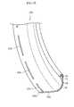
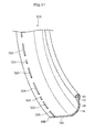
- the segment protrusions 32A may be placed periodically in the tire circumferential direction, as illustrated in Fig. 10 , or they may be placed irregularly in length and separation, as illustrated in Fig. 11 . Irregular placement enables the effects of vibration during running to be suppressed.
- semispherical shaped protrusion domes 32B may be formed along the tire circumferential direction instead of the segment protrusions 32A.
Landscapes
- Engineering & Computer Science (AREA)
- Mechanical Engineering (AREA)
- Tires In General (AREA)
- Tyre Moulding (AREA)
Abstract
Description
- The present invention relates to a tire formed at least partly by a resin material, and a tire manufacturing apparatus and a tire manufacturing method thereof.
- Recently there is demand to employ thermoplastic resins, thermoplastic elastomers, and the like as tire materials in order to reduce weight, and also due to their ease of recycling. For example, a method is described in Patent Document 1 for joining together a pair of tire configuration members (tire frame halves) that are semi-toroidal shaped, divided in the tire axial direction. In the method, separate thermoplastic material that has been melted is infilled to a join portion of the tire frame halves. When this is being performed, the pair of tire configuration members is supported from the tire radial direction inside by a specialized jig.
- Employing the separate thermoplastic material enables the strength of the join portion to be secured. However, various measures need to be taken in order to support the tire frame halves from the tire radial direction inside.
- Patent Document 1: Japanese Patent Application Laid-Open (
JP-A) No. 2011-207166 - In consideration of the above circumstances, an object of the present invention is to provide a tire, tire manufacturing apparatus, and tire manufacturing method with which accurate support is performed with a specialized jig during joining of a pair of tire frame halves, and which obtain an excellent joint.
- A tire according to a first aspect of the present invention includes: a tire frame member that is configured from a pair of tire frame halves, each formed using a resin material and including a bead portion, a side section, and a half-width crown half section, the tire frame halves being aligned with each other and joined together at leading ends of the crown half sections; and an engagement section that is formed on a tire radial direction inner side face of each of the crown half sections further to a tire width direction outer side than a joining portion between the crown half sections, and that engages with an outer face of a support jig that supports the pair of tire frame halves from the tire radial direction inner side during joining so as to restrict movement in a tire width direction with respect to the support jig.
- The crown half sections include regions on which a tread is disposed at the tire radial direction outer side. The bead portions are portions that touch the rim flange. The side portions are regions between the crown half bodies and the bead portion.
- The tire according to the first aspect includes the tire frame member formed by combining the pair of tire frame halves. During manufacture of the tire frame member, when supporting the tire frame halves from the tire radial direction inside, the tire frame halves are pressed toward the tire radial direction outer side by a support jig so as to prevent displacement with respect to the support jig. Sometimes the tire frame halves move toward the tire axial direction outer side with respect to the support jig at this time.
- Thus in the present invention, the engagement section is formed on the tire radial direction inner side face of each of the crown half sections of the tire frame halves further to a tire width direction outer side than the joining portion between the crown half sections, and the engagement section engages with an outer face of the support jig and restricts relative movement in the tire width direction with respect to the support jig. The engagement section includes any shape capable of restricting movement in the tire axial direction of the tire frame halves with respect to the support jig by the relationship between the engagement section and the outer face of the support jig, such as a projection shape, an indentation shape, or a step shape. Engagement of the engagement section with the outer face of the support jig enables movement of the tire frame halves in the tire axial direction with respect to the support jig to be suppressed. This thereby enables the tire frame halves to be supported accurately positioned by the support jig, enabling excellent joining to be obtained.
- In a tire of a second aspect of the present invention, the engagement section is protrusion shaped so as to project from the tire radial direction inner side face of the crown half section.
- This thereby enables the engagement section to be configured simply by forming the engagement section as a projection. Moreover, no thinned portion is formed in the thickness direction of the tire frame member, enabling the strength of the tire to be maintained better than in cases in which an indentation is formed.
- In a tire of a third aspect of the present invention, the engagement section is formed along the tire circumferential direction.
- Due to forming the engagement section along the tire circumferential direction, excellent prevention of relative movement in the axial direction between the tire frame halves and the support jig along the tire circumferential direction can be achieved. The meaning of "along the circumferential direction" includes both forming along the tire circumferential direction, and disposing in a row along the tire circumferential direction. Thus configurations that are segmented in the tire circumferential direction may be adopted, and configurations with dot shapes in a row along the tire circumferential direction may be adopted.
- In a tire according to a fourth aspect of the present invention, the engagement section is formed along the entire circumference in the tire circumferential direction.
- Forming the engagement section along the entire circumference in the tire circumferential direction enables excellent prevention of relative movement in the tire axial direction between the tire frame halves and the support jig at each location in the tire circumferential direction.
- In a tire according to a fifth aspect of the present invention, the engagement section is segmented into plural segments in the tire circumferential direction and disposed irregularly in the tire circumferential direction.
- Such irregular placement in the tire circumferential direction enables the effect of vibration during running to be suppressed.
- A tire manufacturing apparatus according to a sixth aspect of the present invention includes: plural arm sections capable of expanding or contracting in a tire radial direction and extending toward the tire radial direction outer side; a tire support member that is supported from the tire radial direction inner side by leading end portions of the arm sections disposed at the tire radial direction outer side, that is segmented into plural segments in the tire circumferential direction, that has an external face forming a circular ring shape around the inside periphery of the tire frame member, that contacts the inner face of the tire frame member, and supporting the pair of tire frame halves from the tire radial direction inner side; and a support engagement section that is formed on the tire radial direction outer face of the tire support member, and that engages with an engagement section formed further to a tire width direction outer side than a joining portion between the tire frame halves.
- In the tire manufacturing apparatus according to the sixth aspect, the tire support member is supported from the tire radial direction inside by the plural arm sections that extend out toward the radial direction outer side. The tire support member is segmented into plural segments in the tire circumferential direction, and has the external face that forms a circular ring shape around the inside periphery of the tire frame member, contacts the inner face of the tire frame member, and supports the pair of tire frame halves from the tire radial direction inside. When doing so, the support engagement section is formed on the tire radial direction outer face of the tire support member, and engages with the engagement section of the tire frame halves. Thus relative movement between the tire frame halves and the tire support member in the tire axial direction can be prevented, even when pressing force is applied to the tire frame halves toward the tire radial direction outer side from the tire support member in order to prevent displacement with the support jig. The tire frame halves are accordingly supported accurately positioned by the tire support member, enabling excellent joining to be obtained.
- After joining, the arm sections are contracted toward the tire radial direction inside and separated from the tire support member, thereby enabling the tire support member to be removed from the tire frame member from the tire radial direction inside.
- In a tire manufacturing apparatus according to a seventh aspect of the present invention, the support engagement section is an indentation formed at the tire radial direction outer face of the tire support member.
- Configuring the support engagement section as an indentation enables the engagement section on the tire side to be formed as a projection. This means that there are no thin portions formed in the thickness of the tire frame member, enabling the strength of the tire to be better maintained than in cases in which a protrusion is formed (cases in which an indentation is formed at the tire frame member side).
- In a tire manufacturing apparatus according to an eighth aspect of the present invention, the support engagement section is formed along the tire circumferential direction.
- Forming the support engagement section along the tire circumferential direction, enables excellent prevention of relative movement in the tire axial direction between the tire frame halves and the support jig along the tire circumferential direction.
- In the tire manufacturing apparatus according to a ninth aspect of the present invention, the support engagement section is formed along the entire circumference in the tire circumferential direction.
- Forming the support engagement section in this manner along the entire circumference in the tire circumferential direction enables excellent prevention of relative movement in the tire axial direction between the tire frame halves and the support jig at each location in the tire circumferential direction.
- Moreover, not only in cases in which the engagement section on the tire frame half side is formed along the entire circumference of the tire circumferential direction by forming the support engagement section along the entire circumference in the tire circumferential direction, engagement of the engagement section with the support engagement section enables excellent prevention of relative movement between the tire frame halves and the support jig even in cases in which the engagement section is a segmented shape in the tire circumferential direction.
- A tire manufacturing method according to a tenth aspect of the present invention is a tire manufacturing method for manufacturing one tire from out of the first to the fifth aspects using the tire manufacturing apparatus of the sixth aspect, and includes: engaging the engagement section with the support engagement section; adding a resin material and joining the pair of tire frame halves; retracting the leading end portions of the arm sections to the tire radial direction inner side and separating the leading end portions of the arm sections from the tire support member; and removing the tire support member from the inner side of the tire frame halves.
- In the tire manufacturing method according to the tenth aspect, the engagement sections of the tire frame halves are engaged with and supported by the support engagement section of the tire support member. Thus displacement of the tire frame halves in the tire axial direction with respect to the tire support member is prevented, enabling resin material to be added to the pair of tire frame halves and excellent joining to be achieved. When removing the tire frame member from the tire support member after joining, the leading end portions of the arm sections are retracted toward the radial direction inner side and separated from the tire support member, so that the tire support member can be withdrawn from tire radial direction inside.
- The configuration of the tire of the first aspect as explained above enables relative movement in the tire axial direction between the tire frame halves and the support jig to be prevented and the tire frame halves to be supported accurately positioned by the support jig, thereby enabling excellent joining to be achieved.
- Configuring the tire of the second aspect as described above enables the engagement section to be configured simply, and not forming thin portions in the thickness of the tire frame member enables the strength of the tire to be maintained better than in cases in which an indentation is formed.
- Configuring the tire of the third aspect as described above enables excellent prevention to be achieved of relative movement in the tire axial direction between the tire frame halves and the support jig along the tire circumferential direction.
- Configuring the tire of the fourth aspect as described above enables excellent prevention to be achieved of relative movement in the tire axial direction between the tire frame halves and the support jig, at each location in the tire circumferential direction.
- Configuring the tire of the fifth aspect as described above enables the influence of vibration during running to be suppressed.
- Configuring the tire manufacturing apparatus of the sixth aspect as described above enables the tire frame halves to be supported with more accurate positioning by the tire support member, enabling excellent joining to be obtained.
- Due to configuring the tire of the seventh aspect as described above, thinned portions are not formed in the thickness of the tire frame member, enabling the tire strength to be maintained better than in cases in which a protrusion is formed (cases in which an indentation is formed on the tire frame member side).
- Configuring the tire of the eighth aspect as described above enables excellent prevention to be achieved of relative movement in the tire axial direction between the tire frame halves and the support jig along the tire circumferential direction.
- Configuring the tire of the ninth aspect as described above enables excellent prevention to be achieved of relative movement in the tire axial direction between the tire frame halves and the support jig, at each location in the tire circumferential direction.
- Configuring the tire of the tenth aspect as described above enables displacement in the tire axial direction of the tire frame halves with respect to the tire support member to be prevented, enabling the resin material to be adjoined to the pair of tire frame halves, and enabling excellent joining to be obtained.
-
-
Fig. 1 is a perspective view of a cross-section of part of a tire according to an exemplary embodiment of the present invention. -
Fig. 2 is a perspective cross-section of a bead portion of a tire according to an exemplary embodiment of the present invention, mounted to a rim. -
Fig. 3 is a perspective view of a forming machine. -
Fig. 4 is an exploded perspective view of a support jig. -
Fig. 5 is a perspective view of an assembled state of a support jig. -
Fig. 6A is a tire radial direction cross-section of one half of tire frame halves in a state supported by a support jig. -
Fig. 6B is an enlarged cross-section of the join portion inFig. 6A . -
Fig. 7 is an enlarged tire radial direction cross-section in a tire radial direction of one half of tire frame halves in a state supported by a support jig after finishing joining. -
Fig. 8 is a perspective view illustrating part of a forming machine, and joining processing using an extruder. -
Fig. 9A is a face-on view of a tire frame member in a supported state by a support jig, as seen from along the tire axial direction. -
Fig. 9B is a face-on view illustrating an operational state when a tire frame member is being removed from a support jig. -
Fig. 10 is a perspective view of a tire according to another exemplary embodiment, with a portion illustrated in cross-section. -
Fig. 11 is a perspective view of a tire according to another exemplary embodiment, with a portion illustrated in cross-section. -
Fig. 12 is a perspective view of a tire according to another exemplary embodiment, with a portion illustrated in cross-section. - Examples of exemplary embodiments are given below, and explanation follows regarding the exemplary embodiments of the present invention.
- Explanation first follows regarding a first exemplary embodiment. As illustrated in
Fig. 1 , a tire of the present exemplary embodiment is a pneumatic tire employed by internally filling with air. Atire 10 includes atire frame member 17. Thetire frame member 17 includes a pair ofbead portions 12,side sections 14 that extend out from thebead portions 12 toward the tire radial direction outside, and acrown section 16 that couples together each of theside sections 14 at the tire radial direction outside ends thereof. - The
tire frame member 17 is configured by a pair of tire frame halves 17A that are each integrally formed by asingle bead portion 12, asingle side section 14, and a half-widthcrown half section 16A, and have the same circular ring shape as each other. Leading ends 16B of thecrown half sections 16A are formed with a shape tapering toward the side of the tire equatorial plane CL. -
Protrusions 32 are formed as an engagement section to the tire radial direction inner side face of thecrown half sections 16A. Theprotrusions 32 are disposed further to the tire equatorial plane CL than the center in the tire width direction W of each of thecrown half sections 16A, and are disposed further to the tire width direction outside than the leading ends 16B of thecrown section 16. Theprotrusions 32 are each formed in a ring shape around the entire periphery along the tire circumferential direction. Theprotrusions 32 have semi-circular shaped cross-sections. Theprotrusions 32 engage withindentations 48D serving as a support engagement section, described below. The height H1 of theprotrusions 32 is preferably within the range of from 0.3 mm to 5 mm. This is because there is a possibility of the tire frame halves 17A falling out of engagement and moving in the tire width direction W with respect to atire support member 48, described below, when the height H1 is lower than 0.3 mm, and because the tire frame halves 17A are more difficult to fit to thetire support member 48 when the height H1 is higher than 5 mm. - The pair of tire frame halves 17A are aligned with each other at the leading ends 16B of the
crown half sections 16A, so as to form thetire frame member 17 by joining the portions at the tire equatorial plane CL together. Athermoplastic welding material 19 is employed at the join between portions at the tire equatorial plane CL. - As illustrated in
Fig. 2 , each of the pairs ofbead portions 12 makes close contact with abead seat 21 and arim flange 22 of a rim, so as to maintain the internal pressure of air filled inner side the tire. Atread member 30 configuring a tire tread that is the ground contact portion of the tire is disposed at the tire radial direction outside of thecrown section 16. - The
tire frame member 17 is formed from a resin material. The resin material employed here does not encompass vulcanized rubber. Examples of the resin material include thermoplastic resins (including thermoplastic elastomers), thermoset resins, and other general purpose resins, and also include engineering plastics (including super engineering plastics). - Thermoplastic resins (including thermoplastic elastomers) are polymer compounds of materials that soften and flow with increased temperature, and that adopt a relatively rigid and strong state when cooled. In the present specification, out of these, distinction is made between polymer compounds forming materials that soften and flow with increasing temperature, that adopt a relatively hard and strong state on cooling, and that have a rubber-like elasticity, considered to be thermoplastic elastomers, and polymer compounds forming materials that soften and flow with increasing temperature, that adopt a relatively hard and strong state on cooling, and do not have a rubber-like elasticity, considered to be non-elastomer thermoplastic resins.
- Examples of thermoplastic resins (thermoplastic elastomers included) include thermoplastic polyolefin-based elastomers (TPO), thermoplastic polystyrene-based elastomers (TPS), thermoplastic polyamide-based elastomers (TPA), thermoplastic polyurethane-based elastomers (TPU), thermoplastic polyester-based elastomers (TPC), and dynamically crosslinking-type thermoplastic elastomers (TPV), as well as thermoplastic polyolefin-based resins, thermoplastic polystyrene-based resins, thermoplastic polyamide-based resins, and thermoplastic polyester-based resins.
- Such thermoplastic resin materials have, for example, a deflection temperature under load (at 0.45 MPa during loading), as defined by ISO 75-2 or ASTM D648, of 78°C or greater, a tensile yield strength, as defined by JIS K7113, of 10 MPa or greater, and a tensile elongation at break (JIS K7113), also as defined by JIS K7113, of 50% or greater. Materials with a Vicat softening temperature, as defined in JIS K7206 (method A), of 130°C or higher may be employed.
- Thermoset resins are curable polymer compounds that form a 3 dimensional mesh structure with increasing temperature. Examples of thermoset resins include phenolic resins, epoxy resins, melamine resins, and urea resins.
- In addition to the above thermoplastic resins (including thermoplastic elastomers) and thermoset resins, general purpose resins may also be employed, such as meth(acrylic)-based resins, EVA resins, vinyl chloride resins, fluororesins, and silicone-based resins.
- In the present exemplary embodiment, explanation follows regarding a case in which the
tire frame member 17 is formed from a thermoplastic resin. - The
tire frame halves 17A formed using a thermoplastic resin may, for example, be molded using vacuum forming, pressure forming, injection molding, or melt casting. The manufacturing processes can be greatly simplified, and the forming time shortened, in comparison to rubber forming (vulcanizing). - The
tire frame member 17 may be configured from a single thermoplastic resin material, or, similarly to conventional ordinary pneumatic tires, may employ thermoplastic resin materials having different characteristics from each other in each of the locations of the tire frame member 17 (theside sections 14, thecrown section 16, thebead portions 12, etc.). - A circular ring shaped
bead core 15 is embedded in each of thebead portions 12 of thetire frame member 17. Thebead core 15 is formed from a steel cord, similarly to in conventional ordinary pneumatic tires. Thebead core 15 may be omitted as long as the rigidity of thebead portions 12 is secured, and there are no problems in fitting to arim 20. Thebead core 15 may be formed from a cord other than steel, such as an organic fiber cord, or a cord of organic fiber covered in resin. Thebead core 15 may also be formed not from a cord, but from a hard resin, by extrusion molding or the like. - A
reinforcement layer 28 formed from a spirally woundsteel cord 26 is disposed on thecrown section 16 of thetire frame member 17. Thereinforcement layer 28 is equivalent to a belt that is disposed at the outer peripheral face of a carcass in a conventional rubber-made pneumatic tire. - Covering layers 24 are formed spanning from the
bead portions 12 to thetire frame member 17 at the tire axial direction W outsides of thecrown section 16. The end portion of thecovering layer 24 on thebead portion 12 side is disposed further to the tire inner side than the close contact portion of thebead portion 12 with therim 20. The end portion of thecovering layer 24 on thetread member 30 side is formed up to the tire axial direction W outside end of thecrown section 16. When thetire 10 has been assembled to therim 20, the coveringlayer 24 tightly seals an air fill space inner side thetire 10 by making close contact with therim 20. - A material having a higher weather resistance than the
tire frame member 17 may be employed as a covering layer material for configuring thecovering layer 24. The covering layer material is preferably a material with better sealing properties than the material configuring thetire frame member 17. The modulus of elasticity of thecovering layer 24 is preferably lower than the modulus of elasticity of thetire frame member 17. This thereby enables appropriate sealing to be achieved against therim 20, while maintaining the rigidity of thetire frame member 17. - A
tread member 30 is disposed at the tire radial direction outside of thetire frame member 17. Thetread member 30 is disposed along thetire frame member 17, and configures a tire tread, which is a ground contact portion of thetire 10. Thetread member 30 is layered onto thetire frame member 17, with anintermediate rubber 34 in between. - The
tread member 30 is formed from a rubber with better wear resistance properties than the thermoplastic resin forming theside sections 14. The rubber employed in thetread member 30 may be the same type of rubber to that employed in conventional ordinary rubber-made pneumatic tires. Another type of thermoplastic resin having better wear resistance properties than the thermoplastic resin forming theside sections 14 may be employed to configure thetread member 30. - Explanation next follows regarding a
tire manufacturing apparatus 39 for thepneumatic tire 10 according to the present exemplary embodiment. -
Fig. 3 andFig. 8 are perspective views illustrating relevant portions of thetire manufacturing apparatus 39 being employed during forming thepneumatic tire 10. Thetire manufacturing apparatus 39 includes a forming machine 40 (seeFig. 3 ) and an extruder machine 50 (seeFig. 8 ). As illustrated inFig. 3 , the formingmachine 40 includes a base 41 that is in contact with the floor. A gearedmotor 43 that rotates a horizontally disposedshaft 42 is attached to an upper portion of thebase 41. - A
support jig 44 for supporting the tire frame halves 17A from the tire radial direction inner side is attached to an end side of theshaft 42. As illustrated inFig. 4 ,Fig. 5 ,Fig. 6A, and Fig. 6B , thesupport jig 44 includes acentral attachment section 45, anarm section 46, and atire support member 48. Ahole 45A is formed in thecentral attachment section 45, for insertion of theshaft 42 through the center. Fourstelliform clamp sections 45B are formed so as to project out toward the tire radial direction outside, with thehole 45A at the center thereof. Each of theclamp sections 45B is configured by two plates formed in a row along the tire axial direction, attached such that anarm section 46 is clamped between the two plates. Amale thread 45C that is inserted through anelongated hole 46C, described below, is fixed to one of the two plates configuring theclamp sections 45B. - One end of the
arm section 46 is clamped to theclamp sections 45B, and extends toward the tire radial direction outside. The other end of the arm section 46 (a tire radial direction leadingend portion 46A) is substantially fan shaped and widens out toward the tire radial direction outside, and the outer end is configured in an arc shape. Theelongated hole 46C is formed in thearm section 46 at the extension of each of theclamp sections 45B along the tire radial direction. Themale thread 45C is inserted through theelongated hole 46C from one side of thearm section 46, and projects out toward the other side. A lockingscrew 46B formed with a female thread along an inner circumference thereof is screwed onto themale thread 45C. Each of thearm sections 46 is capable of individually extending or retracting in the tire radial direction. During extension or retraction, the lockingscrew 46B is loosened, themale thread 45C is moved along theelongated hole 46C, and then the lockingscrew 46B is retightened in the moved position. - The
tire support member 48 is configured by eight dividedpieces 48P, which together form a circular ring shape in an assembled state to thearm section 46. The outer radius of thetire support member 48 is set so as to be larger than the internal radius of thecrown section 16 of the tire frame halves 17A. Each of the dividedpieces 48P includes an arc shaped externalperipheral face 48A.Indentations 48D are formed in a circular shape in the external peripheral faces 48A over the entire circumference at positions corresponding to theprotrusions 32 of the tire frame halves 17A. There are a total of two of theindentations 48D formed in thetire support member 48, with each formed corresponding to one of the tire frame halves 17A. Ajoin indentation 48C is formed between the twoindentations 48D, in a straight line around the entire circumference. Thejoin indentation 48C is disposed at a join portion of the pair of tire frame halves 17A, namely, on the tire equatorial plane CL. - A
groove 48B is formed at the tire radial direction inner side of the dividedpieces 48P. Theleading end portion 46A of thearm section 46 is fitted into therespective groove 48B. Thegroove 48B is deeper at the tire circumferential direction outsides of the dividedpieces 48P, and is shallower toward the central portion. - The divided
pieces 48P are assembled by engaging theleading end portion 46A of thearm section 46 with therespective groove 48B. The length of thearm section 46 in the tire radial direction is adjusted according to the diameter of thetire support member 48. There is a respectiveleading end portion 46A disposed at the tire circumferential direction central portion of four out of the eight dividedpieces 48P. The other four are disposed so as to straddle between adjacentleading end portions 46A. - As illustrated in
Fig. 8 , theextruder machine 50 that extrudes thethermoplastic welding material 19 is disposed in the vicinity of the formingmachine 40. Theextruder machine 50 includes aresin discharge nozzle 52 that discharges moltenthermoplastic welding material 19 downwards. - The
thermoplastic welding material 19 is preferably the same thermoplastic material as that configuring thetire frame member 17; however, a different thermoplastic material may be employed as long as welding can be achieved. Utilizing the same material enables the entiretire frame member 17 to be configured from a single thermoplastic material, reducing cost. Utilizing a different material enables materials with preferable characteristics to be employed respectively for the thermoplastic material used in the tire frame member, and thethermoplastic welding material 19 used in the join. - A smoothing
roller 53 is disposed in the vicinity of theresin discharge nozzle 52 at the rotation direction downstream side of the tire frame member 17 (the arrow A side), for pressing and smoothing thethermoplastic welding material 19 that has adhered to the tire outer surface. Acylinder device 54 is disposed to move the smoothingroller 53 upward or downward. Thecylinder device 54 is supported through a frame, not illustrated in the drawings, from asupport column 50A of theextruder machine 50. - A cooling
air discharge nozzle 55 for discharging cooling air is disposed at the downstream side of the smoothingroller 53 in the tire frame member rotation direction. Afan 56 is disposed at the opposite direction side of theresin discharge nozzle 52 to the tire case rotation direction side (the opposite side to the arrow A direction), and a hotair blocking roller 57 is disposed between thefan 56 and theresin discharge nozzle 52. - The
fan 56 is supported by thesupport column 50A of theextruder machine 50 through the non-illustrated frame. Thefan 56 includes anozzle 56A that blows hot air against a join portion between one of the tire frame halves 17A and the other of the tire frame halves 17A in order to heat the join portion. - A
cylinder device 58 is disposed above the hotair blocking roller 57 to move the hotair blocking roller 57 in the up-down direction. Thecylinder device 58 is supported by thesupport column 50A of theextruder machine 50 through the non-illustrated frame. - Explanation next follows regarding a tire frame member forming process of the present exemplary embodiment.
- First, the tire frame halves 17A are formed by mold forming with the
bead cords 15 embedded therein. Indentations are provided inner side the mold so as to correspond to theprotrusions 32, and theprotrusions 32 are integrally formed to the tire frame halves 17A. Theprotrusions 32 have semicircular cross-sections, facilitating de-molding. - Next, the covering
layer 24 is formed, from thebead portions 12 of the tire frame halves 17A up to just before thecrown section 16. Thecovering layer 24 can also be formed by molding. - Then, as illustrated in
Fig. 5 , thesupport jig 44 is assembled so as to have an external diameter slightly larger than the internal diameter of the tire frame halves 17A. Each of the tire frame halves 17A are fitted onto and attached to the outer peripheral side of thetire support member 48 from the tire axial direction W outside. When this is performed, theprotrusions 32 of the tire frame halves 17A engage with theindentations 48D of thetire support member 48. - In the present exemplary embodiment, the external diameter of the
support jig 44 is larger than the internal diameter of the tire frame halves 17A, thereby enabling movement of the tire frame halves 17A in the tire circumferential direction with respect to thetire support member 48 to be suppressed. Theprotrusions 32 of the tire frame halves 17A and theindentations 48D of thetire support member 48 are engaged with each other, thereby enabling movement of the tire frame halves 17A in the tire axial direction W with respect to thetire support member 48 to be suppressed. The pair of tire frame halves 17A can thereby be disposed so as to be accurately positioned. - The
extruder machine 50 is then moved, and, as illustrated inFig. 8 , the join portion between the two tire frame halves 17A (the tire equatorial plane CL of the tire frame member 17) is disposed beneath thefan 56, the hotair blocking roller 57, theresin discharge nozzle 52, thecylinder device 54, and the coolingair discharge nozzle 55. - The hot
air blocking roller 57 and the smoothingroller 53 are then lowered to cause the hotair blocking roller 57 and the smoothingroller 53 to contact the outer periphery of the abutting portion of the two tire frame halves 17A. Hot air from thefan 56 is then blown against the join portion of the pair of tire frame halves 17A while rotating thetire frame member 17 supported by thetire support member 48 in the arrow A direction. The surface of the portion where thethermoplastic welding material 19 will be adhered is thereby progressively softened or melted (pre-heating process). - The pre-heated portion is then moved toward the rotation direction downstream side (the arrow A direction side), and the
thermoplastic welding material 19 is extruded in a molten state from theresin discharge nozzle 52, and progressively adhered to the join portion (joining process). - The molten
thermoplastic welding material 19 is then progressively pressed from the radial direction outside toward the inner side by the smoothingroller 53, and the surface of thethermoplastic welding material 19 is smoothed so as to be substantially flat. A portion of thethermoplastic welding material 19 is pressed in between the tire frame halves 17A toward the tire radial direction inner side, so as to fill thejoin indentation 48C formed to the outer peripheral face of thetire support member 48. As illustrated inFig. 7 , at the join portion, a substantially triangular indentation formed by theleading end 16B of one of thecrown half sections 16A and theleading end 16B of the other of thecrown half sections 16A is thereby filled in by thethermoplastic welding material 19. Part of the moltenthermoplastic welding material 19 fills thejoin indentation 48C, and the moltenthermoplastic welding material 19 is adhered at a constant width to the inner peripheral face from the portion where the leading ends 16B abut each other. - Thus in the present exemplary embodiment, due to the
thermoplastic welding material 19 being adhered to the inner peripheral face at the outer peripheral side of the tire frame halves 17A and a large contact surface area being achieved, a high adhesive strength is obtained, and in particular strength against bending deformation is strengthened. - The
thermoplastic welding material 19 that has adhered to the tire frame halves 17A then gradually hardens, the pair of tire frame halves 17A are welded together by thethermoplastic welding material 19, and thetire frame member 17 is obtained with the two tire frame halves 17A completely integrated together. - Next, the
extruder machine 50 is retracted, a cord supply device (not illustrated in the drawings) is disposed in the vicinity of thesupport jig 44, and theheated reinforcement cord 26 is wound in a spiral shape onto the outer peripheral face of thetire frame member 17 to form thereinforcement layer 28. Thereinforcement cord 26 can be easily embedded in the resin material by winding on while melting the resin by heating the resin covered steel cord. - One turn of the already vulcanized, band shaped
tread member 30 is then wound onto the outer peripheral face of thetire frame member 17 and thetread member 30 is bonded to the outer peripheral face of thetire frame member 17. Bonding is performed here by employing, for example, a bonding agent or non-vulcanized rubber (post processing with sulfur is performed to achieve bonding when non-vulcanized rubber is employed). Thetread member 30 may employ a pre-cured tread such as those employed in known remolded tires. The process here is similar to the process to adhere the pre-cured tread to the outer peripheral face of a base tire for a remolded tire. - The
tire 10 is then removed from thetire support member 48. When this is performed, as illustrated inFig. 9A , the locking screws 46B are loosened from a state in which thearm sections 46 have been extended and support thetire support member 48, and, as illustrated inFig. 9B , thearm sections 46 are retracted. Theleading end portions 46A are thereby moved away from thetire support member 48, and each of the dividedpieces 48P is removed from the inner side of thetire frame member 17. This thereby completes thetire 10. - In the
tire 10 of the present exemplary embodiment, theprotrusions 32 are formed to the tire radial direction inner side face of thecrown half sections 16A of the tire frame halves 17A. Thus by engaging theprotrusions 32 with theindentations 48D formed to the tire radial direction outside face of thetire support member 48, movement of the tire frame halves 17A in the tire axial direction W with respect to thetire support member 48 can be suppressed. The tire frame halves 17A are thereby supported in an accurate position by thetire support member 48, enabling excellent joining to be obtained. - The
protrusions 32 have semicircular cross-sections, enabling strength against deformation when running the tire to be raised. Easy de-molding is also achieved during forming the tire frame halves 17A by molding. Theprotrusions 32 do not necessarily have to have a semicircular cross-section shape, and may have a triangular shape. However, the corner portions of a cross-section of theprotrusions 32 are preferably a rounded shape. - In the present exemplary embodiment, the
protrusions 32 were formed on the tire frame halves 17A side, and theindentations 48D were formed on thetire support member 48 side, however indentations may be formed on the tire frame halves 17A side, and protrusions may be formed on thetire support member 48 side. Forming theprotrusions 32 on the tire frame halves 17A side, as in the present exemplary embodiment, means that there are no thin portions formed in the thickness of thetire frame member 17, enabling the strength of the tire to be better maintained than in cases in which indentations are formed on the tire frame halves 17A side. - A step may also be formed by making the thickness at the
leading end 16B side of thecrown half sections 16A of the tire frame halves 17A thicker, and a step may also be formed on thetire support member 48 side so as to correspond to, and engage with the tire side step. - In the present exemplary embodiment, the
protrusions 32 are formed in the tire circumferential direction around the entire circumference of the tire frame halves 17A, enabling excellent suppression of movement of thetire frame member 17 in the tire axial direction W with respect to thetire support member 48 of each location in the tire circumferential direction. - Although in the above exemplary embodiment the
protrusions 32 are formed around the entire circumference of the tire frame halves 17A in the tire circumferential direction, theprotrusions 32 may be configured bysegment protrusions 32A that are segmented in the tire circumferential direction as illustrated inFig. 10 . - The segment protrusions 32Amay be placed periodically in the tire circumferential direction, as illustrated in
Fig. 10 , or they may be placed irregularly in length and separation, as illustrated inFig. 11 . Irregular placement enables the effects of vibration during running to be suppressed. - As illustrated in
Fig. 12 , semispherical shaped protrusion domes 32B may be formed along the tire circumferential direction instead of thesegment protrusions 32A.
Claims (10)
- A tire comprising:a tire frame member that is configured from a pair of tire frame halves, each configured using a resin material and including a bead portion, a side section, and a half-width crown half section, the tire frame halves being aligned with each other and joined together at leading ends of the crown half sections; andan engagement section that is formed on a tire radial direction inner side face of each of the crown half sections, further to a tire width direction outer side than a joining portion between the crown half sections, and that engages with an outer face of a support jig that supports the pair of tire frame halves from the tire radial direction inner side during joining so as to restrict movement in a tire width direction with respect to the support jig.
- The tire of claim 1, wherein the engagement section is protrusion shaped so as to project from the tire radial direction inner side face of the crown half section.
- The tire of claim 1 or claim 2, wherein the engagement section is formed along a tire circumferential direction.
- The tire of claim 3, wherein the engagement section is formed along an entire circumference in the tire circumferential direction.
- The tire of claim 3, wherein the engagement section is segmented into a plurality of segments in the tire circumferential direction, which are disposed irregularly in the tire circumferential direction.
- A tire manufacturing apparatus comprising:a plurality of arm sections capable of expanding or contracting in a tire radial direction and extending toward a tire radial direction outer side;a tire support member that is supported from a tire radial direction inner side by leading end portions of the arm sections disposed at the tire radial direction outer side, that is segmented into a plurality of segments in a tire circumferential direction, that has an external face forming a circular ring shape around an inside periphery of a tire frame member, that contacts an inner face of the tire frame member, and that supports a pair of tire frame halves from the tire radial direction inner side; anda support engagement section that is formed on a tire radial direction outer face of the tire support member, and that engages with an engagement section formed further to a tire width direction outer side than a joining portion between the tire frame halves.
- The tire manufacturing apparatus of claim 6, wherein the support engagement section is an indentation formed at the tire radial direction outer face of the tire support member.
- The tire manufacturing apparatus of claim 6 or claim 7, wherein the support engagement section is formed along the tire circumferential direction.
- The tire manufacturing apparatus of claim 8, wherein the support engagement section is formed along an entire circumference in the tire circumferential direction.
- A tire manufacturing method for manufacturing the tire of any one of claim 1 to claim 5 using the tire manufacturing apparatus of claim 6, the tire manufacturing method comprising:engaging the engagement section with the support engagement section;adding a resin material and joining the pair of tire frame halves;retracting the leading end portions of the arm sections to the tire radial direction inner side and separating the leading end portions of the arm sections from the tire support member; andremoving the tire support member from the inner side of the tire frame halves.
Applications Claiming Priority (2)
| Application Number | Priority Date | Filing Date | Title |
|---|---|---|---|
| JP2013031449 | 2013-02-20 | ||
| PCT/JP2014/053669 WO2014129427A1 (en) | 2013-02-20 | 2014-02-17 | Tire, tire manufacturing device, and tire manufacturing method |
Publications (3)
| Publication Number | Publication Date |
|---|---|
| EP2960078A1 true EP2960078A1 (en) | 2015-12-30 |
| EP2960078A4 EP2960078A4 (en) | 2016-10-26 |
| EP2960078B1 EP2960078B1 (en) | 2019-07-24 |
Family
ID=51391219
Family Applications (1)
| Application Number | Title | Priority Date | Filing Date |
|---|---|---|---|
| EP14753629.6A Active EP2960078B1 (en) | 2013-02-20 | 2014-02-17 | Tire, tire manufacturing device, and tire manufacturing method |
Country Status (5)
| Country | Link |
|---|---|
| US (1) | US20150367587A1 (en) |
| EP (1) | EP2960078B1 (en) |
| JP (1) | JP6301306B2 (en) |
| CN (1) | CN104995034B (en) |
| WO (1) | WO2014129427A1 (en) |
Cited By (1)
| Publication number | Priority date | Publication date | Assignee | Title |
|---|---|---|---|---|
| EP2965923A4 (en) * | 2013-03-05 | 2016-03-23 | Bridgestone Corp | Tire |
Families Citing this family (6)
| Publication number | Priority date | Publication date | Assignee | Title |
|---|---|---|---|---|
| JP6444671B2 (en) * | 2014-09-12 | 2018-12-26 | 株式会社ブリヂストン | Pneumatic tire |
| JP6474225B2 (en) * | 2014-10-15 | 2019-02-27 | 株式会社ブリヂストン | Pneumatic tire |
| JP6689029B2 (en) * | 2015-03-24 | 2020-04-28 | 株式会社ブリヂストン | Non-pneumatic tire |
| JP2018065425A (en) * | 2016-10-18 | 2018-04-26 | 株式会社ブリヂストン | tire |
| NL2021842B1 (en) * | 2018-10-19 | 2020-05-13 | Vmi Holland Bv | Tire building drum and method for tire building |
| JP6943275B2 (en) * | 2019-10-10 | 2021-09-29 | 住友ゴム工業株式会社 | Pneumatic tires |
Family Cites Families (16)
| Publication number | Priority date | Publication date | Assignee | Title |
|---|---|---|---|---|
| GB1075644A (en) * | 1964-10-10 | 1967-07-12 | Bayer Ag | Process for the manufacture of pneumatic tyres |
| JP2800943B2 (en) * | 1989-10-02 | 1998-09-21 | 住友ゴム工業 株式会社 | Pneumatic tire |
| DE69014834T2 (en) * | 1989-11-01 | 1995-05-04 | Sumitomo Rubber Ind | Tire. |
| JP2528189Y2 (en) * | 1990-08-28 | 1997-03-05 | 松下電工株式会社 | Electric razor outer blade protection cap |
| JPH05116504A (en) * | 1991-04-15 | 1993-05-14 | Sumitomo Rubber Ind Ltd | Pneumatic tire |
| JP2733427B2 (en) * | 1993-06-11 | 1998-03-30 | 住友ゴム工業株式会社 | Tire reinforcement structure molding equipment |
| US20120267031A1 (en) * | 2003-11-21 | 2012-10-25 | William David Mawby | Tire manufacturing method for improving the uniformity of a tire |
| JP4984614B2 (en) * | 2006-04-11 | 2012-07-25 | 横浜ゴム株式会社 | Pneumatic tire |
| JP2009045757A (en) * | 2007-08-14 | 2009-03-05 | Fujitsu Ltd | Fixing device for transfer mold and method for removing substrate |
| JP5060248B2 (en) * | 2007-11-06 | 2012-10-31 | バンドー化学株式会社 | Flat belt |
| JP2010064566A (en) * | 2008-09-09 | 2010-03-25 | Toyota Motor Corp | Pneumatic tire |
| CN102317087B (en) * | 2009-02-17 | 2014-02-26 | 株式会社普利司通 | Tire and tire manufacturing method |
| JP4981849B2 (en) * | 2009-06-12 | 2012-07-25 | 住友ゴム工業株式会社 | Pneumatic tire and manufacturing method thereof |
| EP2468532B1 (en) * | 2009-08-20 | 2018-05-09 | Bridgestone Corporation | Tire and tire manufacturing method |
| JP5441792B2 (en) | 2010-03-30 | 2014-03-12 | 株式会社ブリヂストン | Tire manufacturing method and tire |
| WO2012026548A1 (en) * | 2010-08-25 | 2012-03-01 | 株式会社ブリヂストン | Tire, and manufacturing method for same |
-
2014
- 2014-02-17 JP JP2015501441A patent/JP6301306B2/en not_active Expired - Fee Related
- 2014-02-17 US US14/767,291 patent/US20150367587A1/en not_active Abandoned
- 2014-02-17 EP EP14753629.6A patent/EP2960078B1/en active Active
- 2014-02-17 CN CN201480009273.0A patent/CN104995034B/en not_active Expired - Fee Related
- 2014-02-17 WO PCT/JP2014/053669 patent/WO2014129427A1/en active Application Filing
Cited By (2)
| Publication number | Priority date | Publication date | Assignee | Title |
|---|---|---|---|---|
| EP2965923A4 (en) * | 2013-03-05 | 2016-03-23 | Bridgestone Corp | Tire |
| US9937757B2 (en) | 2013-03-05 | 2018-04-10 | Bridgestone Corporation | Tire |
Also Published As
| Publication number | Publication date |
|---|---|
| EP2960078B1 (en) | 2019-07-24 |
| WO2014129427A1 (en) | 2014-08-28 |
| EP2960078A4 (en) | 2016-10-26 |
| JP6301306B2 (en) | 2018-03-28 |
| JPWO2014129427A1 (en) | 2017-02-02 |
| CN104995034A (en) | 2015-10-21 |
| CN104995034B (en) | 2017-06-09 |
| US20150367587A1 (en) | 2015-12-24 |
Similar Documents
| Publication | Publication Date | Title |
|---|---|---|
| EP2960078B1 (en) | Tire, tire manufacturing device, and tire manufacturing method | |
| US9138951B2 (en) | Tire and tire manufacturing method | |
| EP2987649B1 (en) | Tire and method for producing tire | |
| EP2468531B1 (en) | Tire and tire manufacturing method | |
| EP2987650B1 (en) | Tire and method for producing tire | |
| JP6138695B2 (en) | tire | |
| EP2468532B1 (en) | Tire and tire manufacturing method | |
| JP5604215B2 (en) | Tire manufacturing method and tire | |
| KR20110113208A (en) | Tire and tire manufacturing method | |
| JP5419591B2 (en) | Tire and tire manufacturing method. | |
| EP3290230B1 (en) | Tire | |
| JP5988559B2 (en) | tire | |
| US9937757B2 (en) | Tire | |
| EP3192646B1 (en) | Method for manufacturing tire, and tire | |
| JP5441792B2 (en) | Tire manufacturing method and tire |
Legal Events
| Date | Code | Title | Description |
|---|---|---|---|
| PUAI | Public reference made under article 153(3) epc to a published international application that has entered the european phase |
Free format text: ORIGINAL CODE: 0009012 |
|
| 17P | Request for examination filed |
Effective date: 20150818 |
|
| AK | Designated contracting states |
Kind code of ref document: A1 Designated state(s): AL AT BE BG CH CY CZ DE DK EE ES FI FR GB GR HR HU IE IS IT LI LT LU LV MC MK MT NL NO PL PT RO RS SE SI SK SM TR |
|
| AX | Request for extension of the european patent |
Extension state: BA ME |
|
| DAX | Request for extension of the european patent (deleted) | ||
| A4 | Supplementary search report drawn up and despatched |
Effective date: 20160923 |
|
| RIC1 | Information provided on ipc code assigned before grant |
Ipc: B60C 5/01 20060101AFI20160919BHEP Ipc: B60C 7/00 20060101ALI20160919BHEP Ipc: B29D 30/08 20060101ALI20160919BHEP |
|
| GRAP | Despatch of communication of intention to grant a patent |
Free format text: ORIGINAL CODE: EPIDOSNIGR1 |
|
| STAA | Information on the status of an ep patent application or granted ep patent |
Free format text: STATUS: GRANT OF PATENT IS INTENDED |
|
| INTG | Intention to grant announced |
Effective date: 20190306 |
|
| GRAS | Grant fee paid |
Free format text: ORIGINAL CODE: EPIDOSNIGR3 |
|
| GRAA | (expected) grant |
Free format text: ORIGINAL CODE: 0009210 |
|
| STAA | Information on the status of an ep patent application or granted ep patent |
Free format text: STATUS: THE PATENT HAS BEEN GRANTED |
|
| AK | Designated contracting states |
Kind code of ref document: B1 Designated state(s): AL AT BE BG CH CY CZ DE DK EE ES FI FR GB GR HR HU IE IS IT LI LT LU LV MC MK MT NL NO PL PT RO RS SE SI SK SM TR |
|
| REG | Reference to a national code |
Ref country code: GB Ref legal event code: FG4D |
|
| REG | Reference to a national code |
Ref country code: CH Ref legal event code: EP |
|
| REG | Reference to a national code |
Ref country code: DE Ref legal event code: R096 Ref document number: 602014050494 Country of ref document: DE |
|
| REG | Reference to a national code |
Ref country code: AT Ref legal event code: REF Ref document number: 1157727 Country of ref document: AT Kind code of ref document: T Effective date: 20190815 |
|
| REG | Reference to a national code |
Ref country code: IE Ref legal event code: FG4D |
|
| REG | Reference to a national code |
Ref country code: NL Ref legal event code: MP Effective date: 20190724 |
|
| REG | Reference to a national code |
Ref country code: LT Ref legal event code: MG4D |
|
| REG | Reference to a national code |
Ref country code: AT Ref legal event code: MK05 Ref document number: 1157727 Country of ref document: AT Kind code of ref document: T Effective date: 20190724 |
|
| PG25 | Lapsed in a contracting state [announced via postgrant information from national office to epo] |
Ref country code: SE Free format text: LAPSE BECAUSE OF FAILURE TO SUBMIT A TRANSLATION OF THE DESCRIPTION OR TO PAY THE FEE WITHIN THE PRESCRIBED TIME-LIMIT Effective date: 20190724 Ref country code: AT Free format text: LAPSE BECAUSE OF FAILURE TO SUBMIT A TRANSLATION OF THE DESCRIPTION OR TO PAY THE FEE WITHIN THE PRESCRIBED TIME-LIMIT Effective date: 20190724 Ref country code: PT Free format text: LAPSE BECAUSE OF FAILURE TO SUBMIT A TRANSLATION OF THE DESCRIPTION OR TO PAY THE FEE WITHIN THE PRESCRIBED TIME-LIMIT Effective date: 20191125 Ref country code: NL Free format text: LAPSE BECAUSE OF FAILURE TO SUBMIT A TRANSLATION OF THE DESCRIPTION OR TO PAY THE FEE WITHIN THE PRESCRIBED TIME-LIMIT Effective date: 20190724 Ref country code: BG Free format text: LAPSE BECAUSE OF FAILURE TO SUBMIT A TRANSLATION OF THE DESCRIPTION OR TO PAY THE FEE WITHIN THE PRESCRIBED TIME-LIMIT Effective date: 20191024 Ref country code: NO Free format text: LAPSE BECAUSE OF FAILURE TO SUBMIT A TRANSLATION OF THE DESCRIPTION OR TO PAY THE FEE WITHIN THE PRESCRIBED TIME-LIMIT Effective date: 20191024 Ref country code: FI Free format text: LAPSE BECAUSE OF FAILURE TO SUBMIT A TRANSLATION OF THE DESCRIPTION OR TO PAY THE FEE WITHIN THE PRESCRIBED TIME-LIMIT Effective date: 20190724 Ref country code: LT Free format text: LAPSE BECAUSE OF FAILURE TO SUBMIT A TRANSLATION OF THE DESCRIPTION OR TO PAY THE FEE WITHIN THE PRESCRIBED TIME-LIMIT Effective date: 20190724 Ref country code: HR Free format text: LAPSE BECAUSE OF FAILURE TO SUBMIT A TRANSLATION OF THE DESCRIPTION OR TO PAY THE FEE WITHIN THE PRESCRIBED TIME-LIMIT Effective date: 20190724 |
|
| PG25 | Lapsed in a contracting state [announced via postgrant information from national office to epo] |
Ref country code: GR Free format text: LAPSE BECAUSE OF FAILURE TO SUBMIT A TRANSLATION OF THE DESCRIPTION OR TO PAY THE FEE WITHIN THE PRESCRIBED TIME-LIMIT Effective date: 20191025 Ref country code: LV Free format text: LAPSE BECAUSE OF FAILURE TO SUBMIT A TRANSLATION OF THE DESCRIPTION OR TO PAY THE FEE WITHIN THE PRESCRIBED TIME-LIMIT Effective date: 20190724 Ref country code: IS Free format text: LAPSE BECAUSE OF FAILURE TO SUBMIT A TRANSLATION OF THE DESCRIPTION OR TO PAY THE FEE WITHIN THE PRESCRIBED TIME-LIMIT Effective date: 20191124 Ref country code: RS Free format text: LAPSE BECAUSE OF FAILURE TO SUBMIT A TRANSLATION OF THE DESCRIPTION OR TO PAY THE FEE WITHIN THE PRESCRIBED TIME-LIMIT Effective date: 20190724 Ref country code: AL Free format text: LAPSE BECAUSE OF FAILURE TO SUBMIT A TRANSLATION OF THE DESCRIPTION OR TO PAY THE FEE WITHIN THE PRESCRIBED TIME-LIMIT Effective date: 20190724 Ref country code: ES Free format text: LAPSE BECAUSE OF FAILURE TO SUBMIT A TRANSLATION OF THE DESCRIPTION OR TO PAY THE FEE WITHIN THE PRESCRIBED TIME-LIMIT Effective date: 20190724 |
|
| PG25 | Lapsed in a contracting state [announced via postgrant information from national office to epo] |
Ref country code: TR Free format text: LAPSE BECAUSE OF FAILURE TO SUBMIT A TRANSLATION OF THE DESCRIPTION OR TO PAY THE FEE WITHIN THE PRESCRIBED TIME-LIMIT Effective date: 20190724 |
|
| PG25 | Lapsed in a contracting state [announced via postgrant information from national office to epo] |
Ref country code: DK Free format text: LAPSE BECAUSE OF FAILURE TO SUBMIT A TRANSLATION OF THE DESCRIPTION OR TO PAY THE FEE WITHIN THE PRESCRIBED TIME-LIMIT Effective date: 20190724 Ref country code: PL Free format text: LAPSE BECAUSE OF FAILURE TO SUBMIT A TRANSLATION OF THE DESCRIPTION OR TO PAY THE FEE WITHIN THE PRESCRIBED TIME-LIMIT Effective date: 20190724 Ref country code: IT Free format text: LAPSE BECAUSE OF FAILURE TO SUBMIT A TRANSLATION OF THE DESCRIPTION OR TO PAY THE FEE WITHIN THE PRESCRIBED TIME-LIMIT Effective date: 20190724 Ref country code: EE Free format text: LAPSE BECAUSE OF FAILURE TO SUBMIT A TRANSLATION OF THE DESCRIPTION OR TO PAY THE FEE WITHIN THE PRESCRIBED TIME-LIMIT Effective date: 20190724 Ref country code: RO Free format text: LAPSE BECAUSE OF FAILURE TO SUBMIT A TRANSLATION OF THE DESCRIPTION OR TO PAY THE FEE WITHIN THE PRESCRIBED TIME-LIMIT Effective date: 20190724 |
|
| PG25 | Lapsed in a contracting state [announced via postgrant information from national office to epo] |
Ref country code: CZ Free format text: LAPSE BECAUSE OF FAILURE TO SUBMIT A TRANSLATION OF THE DESCRIPTION OR TO PAY THE FEE WITHIN THE PRESCRIBED TIME-LIMIT Effective date: 20190724 Ref country code: SK Free format text: LAPSE BECAUSE OF FAILURE TO SUBMIT A TRANSLATION OF THE DESCRIPTION OR TO PAY THE FEE WITHIN THE PRESCRIBED TIME-LIMIT Effective date: 20190724 Ref country code: SM Free format text: LAPSE BECAUSE OF FAILURE TO SUBMIT A TRANSLATION OF THE DESCRIPTION OR TO PAY THE FEE WITHIN THE PRESCRIBED TIME-LIMIT Effective date: 20190724 Ref country code: IS Free format text: LAPSE BECAUSE OF FAILURE TO SUBMIT A TRANSLATION OF THE DESCRIPTION OR TO PAY THE FEE WITHIN THE PRESCRIBED TIME-LIMIT Effective date: 20200224 |
|
| REG | Reference to a national code |
Ref country code: DE Ref legal event code: R097 Ref document number: 602014050494 Country of ref document: DE |
|
| PLBE | No opposition filed within time limit |
Free format text: ORIGINAL CODE: 0009261 |
|
| STAA | Information on the status of an ep patent application or granted ep patent |
Free format text: STATUS: NO OPPOSITION FILED WITHIN TIME LIMIT |
|
| PG2D | Information on lapse in contracting state deleted |
Ref country code: IS |
|
| 26N | No opposition filed |
Effective date: 20200603 |
|
| PG25 | Lapsed in a contracting state [announced via postgrant information from national office to epo] |
Ref country code: SI Free format text: LAPSE BECAUSE OF FAILURE TO SUBMIT A TRANSLATION OF THE DESCRIPTION OR TO PAY THE FEE WITHIN THE PRESCRIBED TIME-LIMIT Effective date: 20190724 |
|
| REG | Reference to a national code |
Ref country code: CH Ref legal event code: PL |
|
| GBPC | Gb: european patent ceased through non-payment of renewal fee |
Effective date: 20200217 |
|
| REG | Reference to a national code |
Ref country code: BE Ref legal event code: MM Effective date: 20200229 |
|
| PG25 | Lapsed in a contracting state [announced via postgrant information from national office to epo] |
Ref country code: MC Free format text: LAPSE BECAUSE OF FAILURE TO SUBMIT A TRANSLATION OF THE DESCRIPTION OR TO PAY THE FEE WITHIN THE PRESCRIBED TIME-LIMIT Effective date: 20190724 Ref country code: LU Free format text: LAPSE BECAUSE OF NON-PAYMENT OF DUE FEES Effective date: 20200217 |
|
| PG25 | Lapsed in a contracting state [announced via postgrant information from national office to epo] |
Ref country code: CH Free format text: LAPSE BECAUSE OF NON-PAYMENT OF DUE FEES Effective date: 20200229 Ref country code: LI Free format text: LAPSE BECAUSE OF NON-PAYMENT OF DUE FEES Effective date: 20200229 |
|
| PG25 | Lapsed in a contracting state [announced via postgrant information from national office to epo] |
Ref country code: IE Free format text: LAPSE BECAUSE OF NON-PAYMENT OF DUE FEES Effective date: 20200217 Ref country code: GB Free format text: LAPSE BECAUSE OF NON-PAYMENT OF DUE FEES Effective date: 20200217 |
|
| PG25 | Lapsed in a contracting state [announced via postgrant information from national office to epo] |
Ref country code: BE Free format text: LAPSE BECAUSE OF NON-PAYMENT OF DUE FEES Effective date: 20200229 |
|
| PGFP | Annual fee paid to national office [announced via postgrant information from national office to epo] |
Ref country code: DE Payment date: 20220217 Year of fee payment: 9 |
|
| PG25 | Lapsed in a contracting state [announced via postgrant information from national office to epo] |
Ref country code: MT Free format text: LAPSE BECAUSE OF FAILURE TO SUBMIT A TRANSLATION OF THE DESCRIPTION OR TO PAY THE FEE WITHIN THE PRESCRIBED TIME-LIMIT Effective date: 20190724 Ref country code: CY Free format text: LAPSE BECAUSE OF FAILURE TO SUBMIT A TRANSLATION OF THE DESCRIPTION OR TO PAY THE FEE WITHIN THE PRESCRIBED TIME-LIMIT Effective date: 20190724 |
|
| PGFP | Annual fee paid to national office [announced via postgrant information from national office to epo] |
Ref country code: FR Payment date: 20220216 Year of fee payment: 9 |
|
| PG25 | Lapsed in a contracting state [announced via postgrant information from national office to epo] |
Ref country code: MK Free format text: LAPSE BECAUSE OF FAILURE TO SUBMIT A TRANSLATION OF THE DESCRIPTION OR TO PAY THE FEE WITHIN THE PRESCRIBED TIME-LIMIT Effective date: 20190724 |
|
| REG | Reference to a national code |
Ref country code: DE Ref legal event code: R119 Ref document number: 602014050494 Country of ref document: DE |
|
| PG25 | Lapsed in a contracting state [announced via postgrant information from national office to epo] |
Ref country code: FR Free format text: LAPSE BECAUSE OF NON-PAYMENT OF DUE FEES Effective date: 20230228 Ref country code: DE Free format text: LAPSE BECAUSE OF NON-PAYMENT OF DUE FEES Effective date: 20230901 |