EP2959999A1 - Wire electric discharge machine provided with threading unit - Google Patents
Wire electric discharge machine provided with threading unit Download PDFInfo
- Publication number
- EP2959999A1 EP2959999A1 EP15172256.8A EP15172256A EP2959999A1 EP 2959999 A1 EP2959999 A1 EP 2959999A1 EP 15172256 A EP15172256 A EP 15172256A EP 2959999 A1 EP2959999 A1 EP 2959999A1
- Authority
- EP
- European Patent Office
- Prior art keywords
- machining
- disconnection
- core
- electric discharge
- core fixing
- Prior art date
- Legal status (The legal status is an assumption and is not a legal conclusion. Google has not performed a legal analysis and makes no representation as to the accuracy of the status listed.)
- Ceased
Links
- 238000003754 machining Methods 0.000 claims abstract description 251
- 238000000151 deposition Methods 0.000 claims abstract description 25
- 230000006870 function Effects 0.000 description 54
- 238000000034 method Methods 0.000 description 28
- 238000010586 diagram Methods 0.000 description 19
- 238000003466 welding Methods 0.000 description 9
- 238000004804 winding Methods 0.000 description 5
- 238000001816 cooling Methods 0.000 description 3
- 239000012530 fluid Substances 0.000 description 3
- 238000012544 monitoring process Methods 0.000 description 3
- 239000002245 particle Substances 0.000 description 2
- XLYOFNOQVPJJNP-UHFFFAOYSA-N water Substances O XLYOFNOQVPJJNP-UHFFFAOYSA-N 0.000 description 2
- 238000005520 cutting process Methods 0.000 description 1
- 230000005484 gravity Effects 0.000 description 1
- 239000007788 liquid Substances 0.000 description 1
- 239000000463 material Substances 0.000 description 1
- 238000005259 measurement Methods 0.000 description 1
- 238000002844 melting Methods 0.000 description 1
- 230000008018 melting Effects 0.000 description 1
- 230000002093 peripheral effect Effects 0.000 description 1
- 239000000843 powder Substances 0.000 description 1
- 238000011144 upstream manufacturing Methods 0.000 description 1
Images




Classifications
-
- B—PERFORMING OPERATIONS; TRANSPORTING
- B23—MACHINE TOOLS; METAL-WORKING NOT OTHERWISE PROVIDED FOR
- B23H—WORKING OF METAL BY THE ACTION OF A HIGH CONCENTRATION OF ELECTRIC CURRENT ON A WORKPIECE USING AN ELECTRODE WHICH TAKES THE PLACE OF A TOOL; SUCH WORKING COMBINED WITH OTHER FORMS OF WORKING OF METAL
- B23H7/00—Processes or apparatus applicable to both electrical discharge machining and electrochemical machining
- B23H7/02—Wire-cutting
- B23H7/08—Wire electrodes
- B23H7/10—Supporting, winding or electrical connection of wire-electrode
- B23H7/102—Automatic wire threading
-
- B—PERFORMING OPERATIONS; TRANSPORTING
- B23—MACHINE TOOLS; METAL-WORKING NOT OTHERWISE PROVIDED FOR
- B23H—WORKING OF METAL BY THE ACTION OF A HIGH CONCENTRATION OF ELECTRIC CURRENT ON A WORKPIECE USING AN ELECTRODE WHICH TAKES THE PLACE OF A TOOL; SUCH WORKING COMBINED WITH OTHER FORMS OF WORKING OF METAL
- B23H1/00—Electrical discharge machining, i.e. removing metal with a series of rapidly recurring electrical discharges between an electrode and a workpiece in the presence of a fluid dielectric
- B23H1/02—Electric circuits specially adapted therefor, e.g. power supply, control, preventing short circuits or other abnormal discharges
- B23H1/024—Detection of, and response to, abnormal gap conditions, e.g. short circuits
-
- B—PERFORMING OPERATIONS; TRANSPORTING
- B23—MACHINE TOOLS; METAL-WORKING NOT OTHERWISE PROVIDED FOR
- B23H—WORKING OF METAL BY THE ACTION OF A HIGH CONCENTRATION OF ELECTRIC CURRENT ON A WORKPIECE USING AN ELECTRODE WHICH TAKES THE PLACE OF A TOOL; SUCH WORKING COMBINED WITH OTHER FORMS OF WORKING OF METAL
- B23H7/00—Processes or apparatus applicable to both electrical discharge machining and electrochemical machining
- B23H7/02—Wire-cutting
- B23H7/04—Apparatus for supplying current to working gap; Electric circuits specially adapted therefor
Definitions
- the present invention relates to a wire electric discharge machine provided with a disconnection repairing unit for performing disconnection repairing operation while monitoring a position of a core fixing section considering the fact that connection is disabled when the wire electrode reaches a core fixing portion while retracting in a machining route, for the purpose of performing a disconnection repairing operation for repairing disconnection of the wire electrode, when disconnection of the wire electrode occurs during machining using a function of fixing a core to a workpiece (hereinafter referred to as a core fixing function).
- a core fixing function a function of fixing a core to a workpiece
- the core fixing function is a function for performing a core fixing, that is, a function for, by making use of an adhesion phenomenon of component particles of a wire electrode in a wire electric discharge machine to a work piece, accumulating a deposit including the component particles of the wire electrode in a machining groove of the workpiece to fix a core and the workpiece.
- the core fixed to the workpiece by the deposit can be removed from the workpiece by applying an external force to the core through striking or the like. Therefore, conventional processes such as setting a residual stock removal section in a machining shape, performing electric discharge machining, and electric-discharge machining the residual stock removal section again after the end of the machining to cut off the core can be omitted. It is therefore possible to reduce a machining time and improve machining efficiency.
- FIG. 8 is a program example in operating the core fixing function according to a command of the NC program.
- the core fixing function of the wire electric discharge machine is operated according to the command of the NC program.
- a command code for operating the core fixing function is represented as M100.
- a core fixing distance is set to 2 mm.
- FIG. 9 is a diagram showing an example of the machining result obtained when the core fixing function is operated according to the command of the NC program. Machining of a workpiece 40 is started from a machining start hole 41. A wire electrode machines a machining route 42 commanded by the program to form a machining groove 43.
- the core fixing function is enabled.
- the machining advances while accumulating a deposit.
- a portion where the deposit is accumulated is referred to as a core fixing section 45.
- the core fixing section 45 is in a state in which the machining groove is filled with the deposit.
- the core fixing function is disabled.
- the machining advances while forming the machining groove again.
- the program ends in a block N111. At this point, the workpiece 40 and a core 44 are fixed by the core fixing section 45.
- the core 44 can be removed by applying an external force to the core 44 by hitting the core 44 with a hammer or the like.
- a hammer or the like Conventionally, as shown in FIG. 10 , work for providing a residual stock removal section 51 in a machining shape, performing electric discharge machining, and electric-discharge machining the residual stock removal section 51 again in a later process to cut off the core 44 is performed.
- the process can be omitted, it is possible to reduce a machining time and improve machining efficiency.
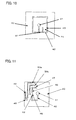
- FIG. 11 is a diagram for explaining disconnection repairing performed using the core fixing function.
- a wire electrode is disconnected in a disconnection position 47.
- the wire electrode travels backward on the machining route for connection in an automatic connection position 48 (see an arrow of reference numeral 50).
- the wire electrode travels backward from the disconnection position 47 to the automatic connection position 48 on the machining route as indicated by reference sign 50a and performs a connection operation and, moving to the disconnection position 47 along the machining route after the connection, then the machining is resumed.
- FIGS. 12A, 12B, and 12C are diagrams showing disconnection repairing by the conventional disconnection repairing unit.
- FIG. 12A there has been devised a method of (1) returning to the machining start hole and automatically connecting the wire electrode, returning to a position where the wire electrode is disconnected on the machining route (hereinafter referred to as a disconnection position) along the machining route, and resuming the electric discharge machining from the disconnection position of the wire electrode.
- FIG. 12B there has been devised a method of automatically connecting the wire electrode in an intermediate position between the disconnection position of the wire electrode and a start point of a machining block in which the disconnection of the wire electrode occurs, returning to the disconnection position along the machining route, and resuming the electric discharge machining from the disconnection position of the wire.
- FIG. 12A there has been devised a method of (1) returning to the machining start hole and automatically connecting the wire electrode, returning to a position where the wire electrode is disconnected on the machining route (hereinafter referred to as a disconnection position) along the machining route, and resuming the electric discharge machining from the disconnection position
- Patent Literatures disclosing techniques of the wire electric discharge machine including the core fixing function will be explained.
- Japanese Patent Laid-Open No. 2012-166332 discloses a workpiece cutoff machining method of preventing a drop of a cutout object from a work piece, breaking a welding section with an external force and cutting off the cutout object without machining a residual stock removal section with electric discharge machining again, and reducing a machining time and improving machining efficiency.
- Japanese Patent Laid-Open No. 2014-24132 discloses a machining program editing method of analyzing a machining program for the plate thickness of a workpiece, the number of machining members, and the specific gravity of the machining members, calculating a machining peripheral length of the machining members and an upper surface area of the shape of the machining members to calculate the mass of the machining members, and, concerning a relation between welding lengths of a retainable welding section to the workpiece of the machining members, calculating, from a map of a measurement value of a controller memory, a predetermined welding length and welding places of the retainable welding section corresponding to the mass of the machining members.
- Japanese Patent Laid-Open No. 2014-14907 discloses a wire electric discharge machine and an automatic programming apparatus for the wire electric discharge machine that can optionally set places where a necessary minimum amount of a deposit is accumulated in order to fix a core to a work thin material.
- Japanese Patent Laid-Open No. 2013-144335 discloses a machining program generating apparatus for a wire electric discharge machine for setting a deposit region from the shape and the weight of a core and generating a machining program on the basis of the deposit region.
- Japanese Patent Laid-Open No. 2011-136409 discloses a disconnection repairing apparatus in wire electric discharge machining in which a wire electrode moves to a position machined most lately among intersections of a circle having a radius drawn around a disconnection position and a machining route and automatic connection of the wire electrode can be performed.
- Japanese Patent Laid-Open No. 8-309622 discloses a disconnection repairing method of automatically connecting a wire electrode in an intermediate position between a disconnection position of the wire electrode and a start point of a block in which disconnection of the wire electrode occurs and resuming electric discharge machining.
- Japanese Patent Laid-Open No. 2-145215 discloses an automatic wire supplying method of automatically connecting a wire in a disconnection position of a wire electrode or a position a small distance back from the disconnection position of the wire electrode along a machining track and resuming electric discharge machining.
- Japanese Patent Laid-Open No. 56-95540 discloses a wire electric discharge machining method of, when wire disconnection occurs during machining, moving to a machining start hole, performing wire automatic supply with an apparatus for automatically supplying a wire electrode, moving to a disconnection point along an original machining track, and resuming machining from the disconnection point and a wire electric discharge machining method of stopping machining when the number of times of occurred wire disconnection is equal to or larger than the designated number of times in the same machining hole and shifting to the next machining.
- connection cannot be performed because the deposit is accumulated in the machining groove in the core fixing section 45 ( FIG. 11 , the moving route 50b to the connection position).
- the wire electrode passes the core fixing section 45 and the connection is completed, if the wire electrode reaches the core fixing section 45 when returning to the disconnection position along the machining route, since the deposit is accumulated in the machining groove 43 and the machining groove 43 is buried in the core fixing section 45, the wire electrode is caught by the deposit and disconnected ( FIGS. 12A, 12B, and 12C , the route 49 returning to the disconnection position). Therefore, even if the wire electrode retracts beyond a terminal of the core fixing section 45 (hereinafter referred to as a core fixing end position 46) and the automatic connection is performed in disconnection repairing, the machining cannot be resumed.
- a core fixing end position 46 a terminal of the core fixing section 45
- Japanese Patent Laid-Open No. 2014-24132 a machining program is analyzed to automatically calculate the length and the place of a core retaining portion. Like Japanese Patent Laid-Open No. 2012-166332 , concerning disconnection during a core fixing function operation, connection can be performed on the site and the machining can be continuously performed. However, there is no description concerning a repairing method of disconnection that occurs after the operation of the core fixing function ends.
- a core fixing place is optionally set when a core fixing function is used.
- a repairing method of disconnection that occurs after the operation of the core fixing function ends.
- Japanese Patent Laid-Open No. 2013-144335 discloses a machining program generating apparatus for a wire electric discharge machine that can deposit components of a wire electrode on a core not via complicated work. However, there is no description concerning a repairing method of disconnection that occurs after the operation of the core fixing function ends.
- Japanese Patent Laid-Open No. 56-95540 automatic connection is performed in a machining start hole.
- Japanese Patent Laid-Open No. 2011-136409 and Japanese Patent Laid-Open No. 8-309622 if the core fixing section is present between the machining start hole and the disconnection position, disconnection occurs again in the return to the disconnection position.
- a condition for shifting to the next machining is that the number of times of disconnection of the wire is equal to or larger than the designated number of times. Therefore, the patent literature is different from the present invention, which checks presence or absence of the core fixing section and determines whether to make a shift to the next machining.
- the automatic connection by the disconnection repairing is performed between a disconnection position and a core fixing end position.
- a wire electric discharge machine provided with a disconnection repairing unit includes: a disconnection repairing unit for performing, when a wire electrode is disconnected during electric discharge machining, automatic connection on a machined machining route, returning to a position where a wire is disconnected along the machining route, and resuming the electric discharge machining from a disconnection position of the wire electrode, and configured to perform a core fixing by, electric-discharge machining of a workpiece with electric discharge generated between the wire electrode and the workpiece and depositing and accumulating machining wastes caused by the electric discharge machining to thereby fix a core generated by the electric discharge machining and the workpiece, and, machine the workpiece along the machining route while controlling the respective moving axes and calculating coordinates of the respective moving axes and a machining distance according to a machining program
- the wire electric discharge machine provided with a disconnection repairing unit includes, a core-fixing-end-position storing unit for storing a core fixing end position of a depositing and
- the disconnection repairing unit may include a core-fixing-end-position determining unit for determining whether the automatic connection position by the disconnection repairing unit is present between the disconnection position and the core fixing end position.
- the disconnection repairing unit may execute the automatic connection.
- the disconnection repairing unit may retract from the disconnection position along the machining route and perform the automatic connection and, when the connection cannot be performed, further repeat an operation for retracting along the machining route and performing the automatic connection.
- the wire electric discharge machine may display an alarm.
- the wire electric discharge machine may skip the machining to the command position and resume the machining from the connection command position.
- the core-fixing-end-position determining unit may include a disconnection-position storing unit for storing, when the wire electrode is disconnected during the electric discharge machining, a disconnection position on the machining route; and a retraction-position calculating unit for calculating a retraction position from the disconnection position when the retraction is performed along the machining route by the disconnection repairing unit.
- the core-fixing-end-position determining unit may determine, from the disconnection position, the core fixing end position, and the retraction position, whether the automatic connection position is present between the disconnection position and the core fixing end position.
- the core-fixing-end-position determining unit may include a retraction-position storing unit for storing, as a retraction position, a position during retraction along the machining route by the disconnection repairing unit.
- the core-fixing-end-position determining unit may determine, from the core fixing end position and the retraction position, whether the automatic connection position is present between the disconnection position and the core fixing end position.
- the present invention includes the components explained above. Therefore, it is possible to provide a wire electric discharge machine that performs automatic connection on a machined machining route when disconnection occurs in machining performed using a core fixing function and a disconnection repairing operation is started.
- the automatic connection by the disconnection repairing is performed between a disconnection position and a core fixing end position.
- FIG. 1 is a diagram schematically showing a main part of the wire electric discharge machine that carries out a method of the present invention.
- the wire electric discharge machine shown in FIG. 1 has a core fixing function.
- An entire main body section of the wire electric discharge machine is roughly divided into two, i.e., an upper machine frame section 1 and a lower machine frame section 2 disposed to be opposed to each other.
- the sections 1 and 2 are attached to be relatively movable in the up-down direction by a not-shown column. This is because it is necessary to adjust, according to the thickness or the like of a work to be machined, an interval between an upper wire electrode guide 7 on a wire electrode feeding route upstream side and a lower wire electrode guide 18 on a wire electrode feeding route downstream side.
- a wire electrode winding-up unit 3 In the upper machine frame section 1, a wire electrode winding-up unit 3, a brake roller 4, a wire electrode fusing mechanism 5, a wire electrode draw-in unit 6, and the upper wire electrode guide 7 are disposed.
- a nozzle for jetting machining fluid to a machining region is provided in the upper wire electrode guide 7.
- the wire electrode winding-up unit 3 includes a supply reel 9 coupled to a winding-up motor 8.
- the brake roller 4 is driven by a brake motor 10 capable of forwardly and reversely rotating via a timing belt, a powder clutch, and the like.
- Reference numeral 11 denotes a pulse coder that detects a rotation amount (a wire electrode movement amount) of the brake roller 4.
- the wire electrode fusing mechanism 5 is configured by a wire electrode feed pipe structure 12 disposed above the upper wire electrode guide 7, a first electrode for wire electrode fusing 13 and a second electrode for wire electrode fusing (substantial wire fusing unit) 14b, which also functions as wire electrode distal end detecting unit 14a, disposed on an inlet side and an outlet side of the wire electrode feed pipe structure 12, and a press contact roller 15.
- the electrode for wire electrode fusing 14b and the press contact roller 15 are capable of moving away from and toward a traveling route of a wire electrode 20.
- the second electrode for wire electrode fusing 14b and the press contact roller 15 are moved to enter the traveling route of the wire electrode 20 in a long hole as shown in FIG. 1 .
- the second electrode for wire electrode fusing 14b and the press contact roller 15 are moved away from the wire electrode 20.
- anneal action is performed by energizing the wire electrode 20 between the first electrode for wire electrode fusing 13 and the second electrode for wire electrode fusing 14b to heat the wire electrode 20 in a state in which cooling air is fed between A and B of the wire electrode feed pipe structure 12.
- the temperature of the wire electrode 20 suddenly rises compared with a portion where the cooling air flows. Therefore, the wire electrode 20 is fused in this position.
- a machining upper electrode 30a is disposed to face a wire electrode passage.
- energization for machining is performed between the machining upper electrode 30a and a machining lower electrode 30b.
- a wire electrode winding roller 17 and a pinch roller 16 and the lower wire electrode guide 18 opposed to the wire electrode winding roller 17 are disposed.
- a nozzle for jetting the machining fluid is provided in the lower wire electrode guide 18.
- Reference numeral 19 denotes a table surface of the wire electric discharge machine.
- the machining lower electrode 30b is disposed to face a wire electrode passage in the lower wire electrode guide 18.
- reference signs 31a and 31b denote intake ports of the machining fluid jetted to the machining region from the nozzles of the upper wire electrode guide 7 and the lower wire electrode guide 18.
- Reference numeral 18a denotes a lower nozzle.
- the wire electrode 20 is drawn out from the supply reel 9, wound around turning rollers 21 and 22, and guided to the brake roller 4.
- the wire electrode 20 forms a wire electrode route that passes the position of the first electrode for wire electrode fusing 13, pierces through the wire electrode feed pipe structure 12 to reach the upper wire electrode guide 7, passes through the lower wire electrode guide 18, changes the direction in a turning roller 23, and reaches the wire electrode winding roller 17.
- the wire electrode 20 is given predetermined back tension by the brake roller 4 driven by the brake motor 10 controlled by a constant current circuit (not shown in the figure).
- the wire electrode 20 travels according to pulling action of the wire electrode winding roller 17.
- the machining lower electrode 30b disposed in the lower wire electrode guide 18 comes into contact with the traveling wire electrode 20 together with the machining upper electrode 30a and supplies electric power for machining to the wire electrode 20.
- the winding-up motor 8 of the supply reel 9 is idled in a reverse direction (a broken line arrow).
- a grip section 26 is in an open state during the normal traveling of the wire electrode 20 and does not come into contact with the wire electrode 20.
- Reference numeral 24 denotes a pinch roller. The pinch roller 24 comes into contact with a circumferential surface of the brake roller 4 to ensure the contact of the wire electrode 20 and the brake roller 4.
- Reference numeral 25 denotes a guide pipe.
- the guide pipe 25 is disposed between the turning roller 23 and the wire electrode winding roller 17 in the lower machine frame section 2. The wire electrode 20 is pierced through the guide pipe 25.
- the wire electrode draw-in unit 6 is configured by an arm 27 provided with the grip section 26 at the distal end and an air cylinder 28 that draws in the arm 27.
- the grip section 26 at the distal end is located on the downstream side of the press contact roller 15.
- the wire electrode draw-in unit 6 is substantial wire electrode removing unit.
- the wire electrode feed pipe structure 12 includes a water guide section and a water discharge section not shown in the figure in positions respectively indicated by arrows A and B. As explained above, anneal is performed between A and B during fusing of the wire electrode 20. The wire electrode 20 is fused in the position of the second electrode for wire electrode fusing 14b.
- the wire electrode feed pipe structure 12 is a structure entirely electrically insulated from the wire electrode 20. Further, the wire electrode feed pipe structure 12 is supported by a slide member 102 together with the first electrode for wire electrode fusing 13. The slide member 102 is driven to rise and fall by a driving unit (not shown) along a column guide 103 between an uppermost position shown in the figure and a positioning section 71 formed in the upper wire electrode guide 7 (a distance L). This mechanism is used during automatic connection.
- the wire electric discharge machine explained above has a core fixing function for performing, when the wire electrode is disconnected during electric discharge machining, automatic connection on a machined machining route, returning to a position where a wire is disconnected along the machining route and performing disconnection repairing for resuming electric discharge machining from a disconnection position of the wire electrode, electric-discharge machining a workpiece through electric discharge generated between the wire electrode and the workpiece, and depositing and accumulating machining wastes caused by the electric discharge machining to thereby fix a core generated by the electric discharge machining and the workpiece.
- the wire electric discharge machine can machine the workpiece along the machining route while controlling the respective moving axes and calculating coordinates of the respective moving axes and a machining distance according to a machining program.
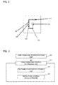
- FIG. 2 is a diagram for explaining a method of disconnection repairing according to several embodiments of the present invention.
- the automatic connection by the disconnection repairing is performed between the disconnection position 47 and the core fixing end position 46.
- FIG. 3 is a block diagram according to a first embodiment.
- a core-fixing-end-position storing unit 60 is unit for capturing a machining distance when a depositing and accumulating operation for machining wastes by the core fixing function ends and storing, as a core fixing end position, a machining distance of a position where the depositing and accumulating operation ends machined most lately among positions at which the depositing and accumulating operation for the machining wastes by the core fixing function ends in a machining shape currently being machined.
- a core-fixing-end-position determining unit 61 includes a disconnection-position storing unit 62 and a retraction-position calculating unit 63.
- the core-fixing-end-position determining unit 61 is unit for determining, from the disconnection position, the retraction position, and the core fixing end position, whether the automatic connection position does not reach the core fixing end position and is present between the disconnection position and the core fixing end position.
- the disconnection-position storing unit 62 is a unit for capturing a machining distance when disconnection occurs during the electric discharge machining and storing the machining distance as a disconnection position.
- the retraction-position calculating unit 63 is a unit for calculating, in retraction along the machining route by the disconnection repairing unit, a retraction position from the disconnection position and setting the calculated retraction position as a retraction position.
- a position where the depositing and accumulating operation for the machining wastes ends is stored in the core-fixing-end-position storing unit 60.
- a machining distance of an end position of the depositing and accumulating operation machined most lately among positions at which the depositing and accumulating operation for the machining wastes by the core fixing function ends in a machining shape currently being machined is stored.
- other position information such as a coordinate may be stored instead of the machining distance.
- the core-fixing-end-position storing unit 60 passes the end position of the depositing and accumulating operation machined most lately among the positions at which the depositing and accumulating operation for the machining wastes by the core fixing function ends to the core-fixing-end-position determining unit 61 as the core fixing end position.
- the disconnection-position storing unit 62 stores a disconnection position on the machining route. A machining distance at the time when disconnection occurs during the electric discharge machining is stored. However, other position information such as a coordinate may be stored instead of the machining distance.
- the retraction-position calculating unit 63 calculates a retraction position viewed from the disconnection position in the retraction along the machining route by the disconnection repairing unit.
- a retraction distance indicating a distance of retraction from the disconnection position during the retraction in the disconnection repairing is calculated.
- other position information such as a coordinate may be calculated instead of the distance.
- FIG. 4 is a diagram for explaining an example of determination of a core fixing end position in the first embodiment.
- the core-fixing-end-position determining unit 61 determines, from the disconnection position, the core fixing end position, and the retraction position, whether the automatic connection position does not reach the core fixing end position and is present between the disconnection position and the core fixing end position. Specifically, the core-fixing-end-position determining unit 61 calculates a difference between the machining distance in the disconnection position and the machining distance in the core fixing end position and compares the difference with the retraction distance. When the retraction distance is smaller than the difference between the machining distance in the disconnection position and the machining distance in the core fixing end position, the core-fixing-end-position determining unit 61 can determine that the automatic connection position is present between the disconnection position and the core fixing end position.
- the core-fixing-end-position determining unit 61 can determine that the automatic connection position is absent between the disconnection position and the core fixing end position.
- the core-fixing-end-position determining unit 61 may perform the determination using a ratio or may perform the determination using other position information such as a coordinate.
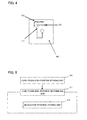
- FIG. 5 is a block diagram according to a second embodiment.
- the core-fixing-end-position storing unit 60 is a unit for capturing a machining distance when a depositing and accumulating operation for machining wastes by the core fixing function ends and storing, as a core fixing end position, a machining distance of a position where the depositing and accumulating operation ends machined most lately among positions at which the depositing and accumulating operation for the machining wastes by the core fixing function ends in a machining shape currently being machined.
- the core-fixing-end-position determining unit 61 includes the retraction-position storing unit 63.
- the core-fixing-end-position determining unit 61 is a unit for determining, from the retraction position and the core fixing end position, whether the automatic connection position does not reach the core fixing end position and is present between the disconnection position and the core fixing end position.
- the retraction-position storing unit 63 is a unit for capturing a machining distance (a distance from a machining start point) in retraction along the machining route by the disconnection repairing unit and storing the machining distance as the retraction position.
- a position where the depositing and accumulating operation for the machining wastes ends is stored in the core-fixing-end-position storing unit 60.
- a machining distance of an end position of the depositing and accumulating operation machined most lately among positions at which the depositing and accumulating operation for the machining wastes by the core fixing function ends in a machining shape currently being machined is stored.
- other position information such as a coordinate may be stored instead of the machining distance.
- the core-fixing-end-position storing unit 60 passes the end position of the depositing and accumulating operation machined most lately among the positions at which the depositing and accumulating operation for the machining wastes by the core fixing function ends to the core-fixing-end-position determining unit 61 as the core fixing end position.
- the retraction-position storing unit 63 stores a retraction position in the retraction along the machining route by the disconnection repairing unit.
- a machining distance from a machining start point is stored as the retraction position.
- other position information such as a coordinate may be stored instead of the machining distance.
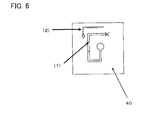
- FIG. 6 is a diagram for explaining an example of determination of a core fixing end position in the second embodiment.
- the core-fixing-end-position determining unit 61 determines, from the core fixing end position and the retraction position, whether the automatic connection position does not reach the core fixing end position and is present between the disconnection position and the core fixing end position. Specifically, the core-fixing-end-position determining unit 61 compares the machining distance during the retraction by the disconnection repairing unit and the machining distance in the core fixing end position. When the machining distance during the retraction by the disconnection repairing unit is larger than the machining distance in the core fixing end position, the core-fixing-end-position determining unit 61 can determine that the automatic connection position is present between the disconnection position and the core fixing end position.
- the core-fixing-end-position determining unit 61 can determine that the automatic connection position is absent between the disconnection position and the core fixing end position.
- the core-fixing-end-position determining unit 61 may perform the determination using a ratio or may perform the determination using other position information such as a coordinate.
- FIG. 7 is a flowchart explaining processing performed when disconnection occurs during electric discharge machining in the machining performed using the core fixing function. The processing will be explained according to respective steps below.
Landscapes
- Engineering & Computer Science (AREA)
- Mechanical Engineering (AREA)
- Chemical & Material Sciences (AREA)
- Chemical Kinetics & Catalysis (AREA)
- Electrochemistry (AREA)
- Electrical Discharge Machining, Electrochemical Machining, And Combined Machining (AREA)
Abstract
Description
- The present invention relates to a wire electric discharge machine provided with a disconnection repairing unit for performing disconnection repairing operation while monitoring a position of a core fixing section considering the fact that connection is disabled when the wire electrode reaches a core fixing portion while retracting in a machining route, for the purpose of performing a disconnection repairing operation for repairing disconnection of the wire electrode, when disconnection of the wire electrode occurs during machining using a function of fixing a core to a workpiece (hereinafter referred to as a core fixing function).
- Conventionally, there have been devised wire electric discharge machines including various core fixing functions. The core fixing function is a function for performing a core fixing, that is, a function for, by making use of an adhesion phenomenon of component particles of a wire electrode in a wire electric discharge machine to a work piece, accumulating a deposit including the component particles of the wire electrode in a machining groove of the workpiece to fix a core and the workpiece.
- The core fixed to the workpiece by the deposit can be removed from the workpiece by applying an external force to the core through striking or the like. Therefore, conventional processes such as setting a residual stock removal section in a machining shape, performing electric discharge machining, and electric-discharge machining the residual stock removal section again after the end of the machining to cut off the core can be omitted. It is therefore possible to reduce a machining time and improve machining efficiency.
- The core fixing function will now be explained with reference to an NC program for machining a workpiece.
-
FIG. 8 is a program example in operating the core fixing function according to a command of the NC program. The core fixing function of the wire electric discharge machine is operated according to the command of the NC program. Note that a command code for operating the core fixing function is represented as M100. A core fixing distance is set to 2 mm. - When the program example (O0100) shown in
FIG. 8 is executed, a machining result shown inFIG. 9 is obtained.FIG. 9 is a diagram showing an example of the machining result obtained when the core fixing function is operated according to the command of the NC program. Machining of aworkpiece 40 is started from amachining start hole 41. A wire electrode machines amachining route 42 commanded by the program to form amachining groove 43. - When M100 is commanded in a block N104 and a block N107, the core fixing function is enabled. The machining advances while accumulating a deposit. A portion where the deposit is accumulated is referred to as a
core fixing section 45. Thecore fixing section 45 is in a state in which the machining groove is filled with the deposit. - When the machining advances 2 mm in a state in which the core fixing function is enabled, the core fixing function is disabled. The machining advances while forming the machining groove again. The program ends in a block N111. At this point, the
workpiece 40 and acore 44 are fixed by thecore fixing section 45. - The
core 44 can be removed by applying an external force to thecore 44 by hitting thecore 44 with a hammer or the like. Conventionally, as shown inFIG. 10 , work for providing a residualstock removal section 51 in a machining shape, performing electric discharge machining, and electric-discharge machining the residualstock removal section 51 again in a later process to cut off thecore 44 is performed. However, since the process can be omitted, it is possible to reduce a machining time and improve machining efficiency. - It is now assumed that disconnection occurs during machining performed using a core retaining function of the wire electric discharge machine.
FIG. 11 is a diagram for explaining disconnection repairing performed using the core fixing function. A wire electrode is disconnected in adisconnection position 47. The wire electrode travels backward on the machining route for connection in an automatic connection position 48 (see an arrow of reference numeral 50). When thecore fixing section 45 is not formed, the wire electrode travels backward from thedisconnection position 47 to theautomatic connection position 48 on the machining route as indicated byreference sign 50a and performs a connection operation and, moving to thedisconnection position 47 along the machining route after the connection, then the machining is resumed. - As a function of automatically repairing disconnection and resuming machining when the disconnection occurs during the machining, various functions have been devised.
FIGS. 12A, 12B, and 12C are diagrams showing disconnection repairing by the conventional disconnection repairing unit. - As shown in
FIG. 12A , there has been devised a method of (1) returning to the machining start hole and automatically connecting the wire electrode, returning to a position where the wire electrode is disconnected on the machining route (hereinafter referred to as a disconnection position) along the machining route, and resuming the electric discharge machining from the disconnection position of the wire electrode. As shown inFIG. 12B , there has been devised a method of automatically connecting the wire electrode in an intermediate position between the disconnection position of the wire electrode and a start point of a machining block in which the disconnection of the wire electrode occurs, returning to the disconnection position along the machining route, and resuming the electric discharge machining from the disconnection position of the wire. As shown inFIG. 12C , there has been devised a method of moving to a position machined most lately among intersections of a circle having a radius drawn around the disconnection position and the machining route and automatically connecting the wire electrode, returning to the disconnection position along the machining route, and resuming the electric discharge machining from the disconnection position of the wire electrode. All the methods are methods of, after performing the automatic connection, returning to the disconnection position along the machining route and resuming the electric discharge machining from the disconnection position of the wire. - Patent Literatures disclosing techniques of the wire electric discharge machine including the core fixing function will be explained.
- Japanese Patent Laid-Open No.
2012-166332 - Japanese Patent Laid-Open No.
2014-24132 - Japanese Patent Laid-Open No.
2014-14907 - Japanese Patent Laid-Open No.
2013-144335 - Japanese Patent Laid-Open No.
2011-136409 - Japanese Patent Laid-Open No.
8-309622 - Japanese Patent Laid-Open No.
2-145215 - Japanese Patent Laid-Open No.
56-95540 - In the case of the machining performed using the core fixing function as explained in the background, connection cannot be performed because the deposit is accumulated in the machining groove in the core fixing section 45 (
FIG. 11 , the movingroute 50b to the connection position). After the wire electrode passes thecore fixing section 45 and the connection is completed, if the wire electrode reaches thecore fixing section 45 when returning to the disconnection position along the machining route, since the deposit is accumulated in themachining groove 43 and themachining groove 43 is buried in thecore fixing section 45, the wire electrode is caught by the deposit and disconnected (FIGS. 12A, 12B, and 12C , theroute 49 returning to the disconnection position). Therefore, even if the wire electrode retracts beyond a terminal of the core fixing section 45 (hereinafter referred to as a core fixing end position 46) and the automatic connection is performed in disconnection repairing, the machining cannot be resumed. - In Japanese Patent Laid-Open No.
2012-166332 - In Japanese Patent Laid-Open No.
2014-24132 2012-166332 - In Japanese Patent Laid-Open No.
2014-14907 - Japanese Patent Laid-Open No.
2013-144335 - In Japanese Patent Laid-Open No.
2011-136409 - In Japanese Patent Laid-Open No.
8-309622 2011-136409 - In Japanese Patent Laid-Open No.
2-145215 - In Japanese Patent Laid-Open No.
56-95540 2011-136409 8-309622 - Therefore, in order to solve the problems of the related art explained above, it is an object of the present invention to provide a wire electric discharge machine that performs automatic connection on a machined machining route when disconnection occurs in machining performed using a core fixing function and a disconnection repairing operation is started. The automatic connection by the disconnection repairing is performed between a disconnection position and a core fixing end position.
- A wire electric discharge machine provided with a disconnection repairing unit according to the present invention includes: a disconnection repairing unit for performing, when a wire electrode is disconnected during electric discharge machining, automatic connection on a machined machining route, returning to a position where a wire is disconnected along the machining route, and resuming the electric discharge machining from a disconnection position of the wire electrode, and configured to perform a core fixing by, electric-discharge machining of a workpiece with electric discharge generated between the wire electrode and the workpiece and depositing and accumulating machining wastes caused by the electric discharge machining to thereby fix a core generated by the electric discharge machining and the workpiece, and, machine the workpiece along the machining route while controlling the respective moving axes and calculating coordinates of the respective moving axes and a machining distance according to a machining program, and the wire electric discharge machine provided with a disconnection repairing unit includes, a core-fixing-end-position storing unit for storing a core fixing end position of a depositing and accumulating operation machined most lately among positions at which the depositing and accumulating operation for the machining wastes by the core fixing function ends in a machining shape currently being machined. The wire electric discharge machine executes automatic connection with the disconnection repairing unit between the disconnection position and the core fixing end position.
- The disconnection repairing unit may include a core-fixing-end-position determining unit for determining whether the automatic connection position by the disconnection repairing unit is present between the disconnection position and the core fixing end position. When the core-fixing-end-position determining unit determines that the automatic connection position is present between the disconnection position and the core fixing end position, the disconnection repairing unit may execute the automatic connection.
- The disconnection repairing unit may retract from the disconnection position along the machining route and perform the automatic connection and, when the connection cannot be performed, further repeat an operation for retracting along the machining route and performing the automatic connection.
- When the core-fixing-end-position determining unit determines that the automatic connection position is absent between the disconnection position and the core fixing end position, the wire electric discharge machine may display an alarm.
- When the core-fixing-end-position determining unit determines that the automatic connection position is absent between the disconnection position and the core fixing end position, when a connection command position is present ahead of a program position during disconnection, the wire electric discharge machine may skip the machining to the command position and resume the machining from the connection command position.
- The core-fixing-end-position determining unit may include a disconnection-position storing unit for storing, when the wire electrode is disconnected during the electric discharge machining, a disconnection position on the machining route; and a retraction-position calculating unit for calculating a retraction position from the disconnection position when the retraction is performed along the machining route by the disconnection repairing unit. The core-fixing-end-position determining unit may determine, from the disconnection position, the core fixing end position, and the retraction position, whether the automatic connection position is present between the disconnection position and the core fixing end position.
- The core-fixing-end-position determining unit may include a retraction-position storing unit for storing, as a retraction position, a position during retraction along the machining route by the disconnection repairing unit. The core-fixing-end-position determining unit may determine, from the core fixing end position and the retraction position, whether the automatic connection position is present between the disconnection position and the core fixing end position.
- The present invention includes the components explained above. Therefore, it is possible to provide a wire electric discharge machine that performs automatic connection on a machined machining route when disconnection occurs in machining performed using a core fixing function and a disconnection repairing operation is started. The automatic connection by the disconnection repairing is performed between a disconnection position and a core fixing end position.
- The above-mentioned objects and characteristics and other objects and characteristics of the present invention will be made apparent from the following explanation of embodiments with reference to accompanying drawings. Among the drawings:
-
FIG. 1 is a diagram for explaining a main part of a wire electric discharge machine that performs a connection operation; -
FIG. 2 is a diagram for explaining a method of disconnection repairing according to several embodiments of the present invention; -
FIG. 3 is a block diagram according to a first embodiment; -
FIG. 4 is a diagram for explaining an example of determination of a core fixing end position in the first embodiment; -
FIG. 5 is a block diagram according to a second embodiment; -
FIG. 6 is a diagram for explaining an example of determination of a core fixing end position in the second embodiment; -
FIG. 7 is a flowchart showing processing according to the present invention; -
FIG. 8 is a program example in operating a core fixing function according to a command by an NC program; -
FIG. 9 is a diagram showing an example of a machining result obtained when the core fixing function is operated according to the command by the NC program; -
FIG. 10 is a diagram showing an example of a machining result obtained when a residual stock removal section is provided to perform machining; -
FIG. 11 is a diagram for explaining disconnection repairing performed when the core fixing function is used; and -
FIGS. 12A, 12B, and 12C are diagrams showing disconnection repairing by conventional disconnection repairing unit. - First, the configuration of a wire electric discharge machine for performing automatic connection will be explained.
FIG. 1 is a diagram schematically showing a main part of the wire electric discharge machine that carries out a method of the present invention. The wire electric discharge machine shown inFIG. 1 has a core fixing function. An entire main body section of the wire electric discharge machine is roughly divided into two, i.e., an uppermachine frame section 1 and a lowermachine frame section 2 disposed to be opposed to each other. Thesections wire electrode guide 7 on a wire electrode feeding route upstream side and a lowerwire electrode guide 18 on a wire electrode feeding route downstream side. - In the upper
machine frame section 1, a wire electrode winding-upunit 3, a brake roller 4, a wireelectrode fusing mechanism 5, a wire electrode draw-inunit 6, and the upperwire electrode guide 7 are disposed. A nozzle for jetting machining fluid to a machining region is provided in the upperwire electrode guide 7. - The wire electrode winding-up
unit 3 includes asupply reel 9 coupled to a winding-upmotor 8. The brake roller 4 is driven by abrake motor 10 capable of forwardly and reversely rotating via a timing belt, a powder clutch, and the like.Reference numeral 11 denotes a pulse coder that detects a rotation amount (a wire electrode movement amount) of the brake roller 4. - The wire
electrode fusing mechanism 5 is configured by a wire electrodefeed pipe structure 12 disposed above the upperwire electrode guide 7, a first electrode for wire electrode fusing 13 and a second electrode for wire electrode fusing (substantial wire fusing unit) 14b, which also functions as wire electrode distalend detecting unit 14a, disposed on an inlet side and an outlet side of the wire electrodefeed pipe structure 12, and apress contact roller 15. The electrode for wire electrode fusing 14b and thepress contact roller 15 are capable of moving away from and toward a traveling route of awire electrode 20. That is, when being used as a wire electrode fusing unit or a wire electrode distal end detecting unit via energization control to a not-shown solenoid, the second electrode for wire electrode fusing 14b and thepress contact roller 15 are moved to enter the traveling route of thewire electrode 20 in a long hole as shown inFIG. 1 . During normal machining, the second electrode for wire electrode fusing 14b and thepress contact roller 15 are moved away from thewire electrode 20. - In this embodiment, anneal action is performed by energizing the
wire electrode 20 between the first electrode for wire electrode fusing 13 and the second electrode for wire electrode fusing 14b to heat thewire electrode 20 in a state in which cooling air is fed between A and B of the wire electrodefeed pipe structure 12. In a position of the second electrode for wire electrode fusing 14b where the cooling air does not flow, the temperature of thewire electrode 20 suddenly rises compared with a portion where the cooling air flows. Therefore, thewire electrode 20 is fused in this position. - In the upper
wire electrode guide 7, a machiningupper electrode 30a is disposed to face a wire electrode passage. During electric discharge machining, energization for machining is performed between the machiningupper electrode 30a and a machininglower electrode 30b. In the lowermachine frame section 2, a wireelectrode winding roller 17 and apinch roller 16 and the lowerwire electrode guide 18 opposed to the wireelectrode winding roller 17 are disposed. In the lowerwire electrode guide 18, a nozzle for jetting the machining fluid is provided.Reference numeral 19 denotes a table surface of the wire electric discharge machine. The machininglower electrode 30b is disposed to face a wire electrode passage in the lowerwire electrode guide 18. Note thatreference signs wire electrode guide 7 and the lowerwire electrode guide 18.Reference numeral 18a denotes a lower nozzle. - The
wire electrode 20 is drawn out from thesupply reel 9, wound around turningrollers wire electrode 20 forms a wire electrode route that passes the position of the first electrode for wire electrode fusing 13, pierces through the wire electrodefeed pipe structure 12 to reach the upperwire electrode guide 7, passes through the lowerwire electrode guide 18, changes the direction in a turningroller 23, and reaches the wireelectrode winding roller 17. - The
wire electrode 20 is given predetermined back tension by the brake roller 4 driven by thebrake motor 10 controlled by a constant current circuit (not shown in the figure). Thewire electrode 20 travels according to pulling action of the wireelectrode winding roller 17. The machininglower electrode 30b disposed in the lowerwire electrode guide 18 comes into contact with the travelingwire electrode 20 together with the machiningupper electrode 30a and supplies electric power for machining to thewire electrode 20. - During normal traveling (during electric discharge machining) of the
wire electrode 20, the winding-upmotor 8 of thesupply reel 9 is idled in a reverse direction (a broken line arrow). Agrip section 26 is in an open state during the normal traveling of thewire electrode 20 and does not come into contact with thewire electrode 20.Reference numeral 24 denotes a pinch roller. Thepinch roller 24 comes into contact with a circumferential surface of the brake roller 4 to ensure the contact of thewire electrode 20 and the brake roller 4.Reference numeral 25 denotes a guide pipe. Theguide pipe 25 is disposed between the turningroller 23 and the wireelectrode winding roller 17 in the lowermachine frame section 2. Thewire electrode 20 is pierced through theguide pipe 25. The wire electrode draw-inunit 6 is configured by anarm 27 provided with thegrip section 26 at the distal end and anair cylinder 28 that draws in thearm 27. Thegrip section 26 at the distal end is located on the downstream side of thepress contact roller 15. The wire electrode draw-inunit 6 is substantial wire electrode removing unit. - The wire electrode
feed pipe structure 12 includes a water guide section and a water discharge section not shown in the figure in positions respectively indicated by arrows A and B. As explained above, anneal is performed between A and B during fusing of thewire electrode 20. Thewire electrode 20 is fused in the position of the second electrode for wire electrode fusing 14b. - The wire electrode
feed pipe structure 12 is a structure entirely electrically insulated from thewire electrode 20. Further, the wire electrodefeed pipe structure 12 is supported by aslide member 102 together with the first electrode for wire electrode fusing 13. Theslide member 102 is driven to rise and fall by a driving unit (not shown) along acolumn guide 103 between an uppermost position shown in the figure and apositioning section 71 formed in the upper wire electrode guide 7 (a distance L). This mechanism is used during automatic connection. - The wire electric discharge machine explained above has a core fixing function for performing, when the wire electrode is disconnected during electric discharge machining, automatic connection on a machined machining route, returning to a position where a wire is disconnected along the machining route and performing disconnection repairing for resuming electric discharge machining from a disconnection position of the wire electrode, electric-discharge machining a workpiece through electric discharge generated between the wire electrode and the workpiece, and depositing and accumulating machining wastes caused by the electric discharge machining to thereby fix a core generated by the electric discharge machining and the workpiece. The wire electric discharge machine can machine the workpiece along the machining route while controlling the respective moving axes and calculating coordinates of the respective moving axes and a machining distance according to a machining program.
-
FIG. 2 is a diagram for explaining a method of disconnection repairing according to several embodiments of the present invention. In the several embodiments of the present invention, when disconnection occurs in the machining performed using the core fixing function and a disconnection repairing operation is started, in the wire electric discharge machine that performs the automatic connection on the machined machining route, the automatic connection by the disconnection repairing is performed between thedisconnection position 47 and the core fixingend position 46. A method of determining whether the wire electrode has reached the core fixing position will now be explained. - A method of monitoring a retraction position viewed from a disconnection position and determining whether the wire electrode has reached the core fixing position
-
FIG. 3 is a block diagram according to a first embodiment. A core-fixing-end-position storing unit 60 is unit for capturing a machining distance when a depositing and accumulating operation for machining wastes by the core fixing function ends and storing, as a core fixing end position, a machining distance of a position where the depositing and accumulating operation ends machined most lately among positions at which the depositing and accumulating operation for the machining wastes by the core fixing function ends in a machining shape currently being machined. - A core-fixing-end-
position determining unit 61 includes a disconnection-position storing unit 62 and a retraction-position calculating unit 63. The core-fixing-end-position determining unit 61 is unit for determining, from the disconnection position, the retraction position, and the core fixing end position, whether the automatic connection position does not reach the core fixing end position and is present between the disconnection position and the core fixing end position. - The disconnection-
position storing unit 62 is a unit for capturing a machining distance when disconnection occurs during the electric discharge machining and storing the machining distance as a disconnection position. The retraction-position calculating unit 63 is a unit for calculating, in retraction along the machining route by the disconnection repairing unit, a retraction position from the disconnection position and setting the calculated retraction position as a retraction position. - When the core fixing function is executed, a position where the depositing and accumulating operation for the machining wastes ends is stored in the core-fixing-end-
position storing unit 60. A machining distance of an end position of the depositing and accumulating operation machined most lately among positions at which the depositing and accumulating operation for the machining wastes by the core fixing function ends in a machining shape currently being machined is stored. However, other position information such as a coordinate may be stored instead of the machining distance. - The core-fixing-end-
position storing unit 60 passes the end position of the depositing and accumulating operation machined most lately among the positions at which the depositing and accumulating operation for the machining wastes by the core fixing function ends to the core-fixing-end-position determining unit 61 as the core fixing end position. The disconnection-position storing unit 62 stores a disconnection position on the machining route. A machining distance at the time when disconnection occurs during the electric discharge machining is stored. However, other position information such as a coordinate may be stored instead of the machining distance. - The retraction-
position calculating unit 63 calculates a retraction position viewed from the disconnection position in the retraction along the machining route by the disconnection repairing unit. A retraction distance indicating a distance of retraction from the disconnection position during the retraction in the disconnection repairing is calculated. However, other position information such as a coordinate may be calculated instead of the distance. -
FIG. 4 is a diagram for explaining an example of determination of a core fixing end position in the first embodiment. - (1) A machining distance in the core fixing end position is stored.
- (2) A machining distance in the disconnection position is stored.
- (3) A retraction distance during the disconnection repairing is calculated.
- (4) When ((the machining distance in the disconnection position) - (the machining distance in the core fixing end position)) > the retraction distance or ((the machining distance in the disconnection position) - (the machining distance in the core fixing end position))/the retraction distance > 1, it is determined that the automatic connection position is present between the disconnection position and the core fixing end position. On the other hand, when ((the machining distance in the disconnection position) - (the machining distance in the core fixing end position)) ≤ the retraction distance or ((the machining distance in the disconnection position) - (the machining distance in the core fixing end position))/the retraction distance ≤ 1, it is determined that the automatic connection position is absent between the disconnection position and the core fixing end position.
- As explained above, the core-fixing-end-
position determining unit 61 determines, from the disconnection position, the core fixing end position, and the retraction position, whether the automatic connection position does not reach the core fixing end position and is present between the disconnection position and the core fixing end position. Specifically, the core-fixing-end-position determining unit 61 calculates a difference between the machining distance in the disconnection position and the machining distance in the core fixing end position and compares the difference with the retraction distance. When the retraction distance is smaller than the difference between the machining distance in the disconnection position and the machining distance in the core fixing end position, the core-fixing-end-position determining unit 61 can determine that the automatic connection position is present between the disconnection position and the core fixing end position. When the retraction distance is equal to or larger than the difference between the machining distance in the disconnection position and the machining distance in the core fixing end position, the core-fixing-end-position determining unit 61 can determine that the automatic connection position is absent between the disconnection position and the core fixing end position. The core-fixing-end-position determining unit 61 may perform the determination using a ratio or may perform the determination using other position information such as a coordinate. - A method of monitoring a machining position during retraction and determining whether the wire electrode has reached the core fixing position
-
FIG. 5 is a block diagram according to a second embodiment. The core-fixing-end-position storing unit 60 is a unit for capturing a machining distance when a depositing and accumulating operation for machining wastes by the core fixing function ends and storing, as a core fixing end position, a machining distance of a position where the depositing and accumulating operation ends machined most lately among positions at which the depositing and accumulating operation for the machining wastes by the core fixing function ends in a machining shape currently being machined. - The core-fixing-end-
position determining unit 61 includes the retraction-position storing unit 63. The core-fixing-end-position determining unit 61 is a unit for determining, from the retraction position and the core fixing end position, whether the automatic connection position does not reach the core fixing end position and is present between the disconnection position and the core fixing end position. The retraction-position storing unit 63 is a unit for capturing a machining distance (a distance from a machining start point) in retraction along the machining route by the disconnection repairing unit and storing the machining distance as the retraction position. - When the core fixing function is executed, a position where the depositing and accumulating operation for the machining wastes ends is stored in the core-fixing-end-
position storing unit 60. A machining distance of an end position of the depositing and accumulating operation machined most lately among positions at which the depositing and accumulating operation for the machining wastes by the core fixing function ends in a machining shape currently being machined is stored. However, other position information such as a coordinate may be stored instead of the machining distance. - The core-fixing-end-
position storing unit 60 passes the end position of the depositing and accumulating operation machined most lately among the positions at which the depositing and accumulating operation for the machining wastes by the core fixing function ends to the core-fixing-end-position determining unit 61 as the core fixing end position. - The retraction-
position storing unit 63 stores a retraction position in the retraction along the machining route by the disconnection repairing unit. A machining distance from a machining start point is stored as the retraction position. However, other position information such as a coordinate may be stored instead of the machining distance. -
FIG. 6 is a diagram for explaining an example of determination of a core fixing end position in the second embodiment. - (1) A machining distance in the core fixing end position is stored.
- (2) A machining distance during disconnection repairing retraction is monitored.
- (3) When (the machining distance in the core fixing end position) < (the machining distance during the disconnection repairing retraction) or (the machining distance in the core fixing end position)/(the machining distance during the disconnection repairing retraction) < 1, it is determined that the automatic connection position is present between the disconnection position and the core fixing end position. On the other hand, when (the machining distance in the core fixing end position) ≥ (the machining distance during the disconnection repairing retraction) or (the machining distance in the core fixing end position)/(the machining distance during the disconnection repairing retraction) ≥ 1, it is determined that the automatic connection position is absent between the disconnection position and the core fixing end position.
- The core-fixing-end-
position determining unit 61 determines, from the core fixing end position and the retraction position, whether the automatic connection position does not reach the core fixing end position and is present between the disconnection position and the core fixing end position. Specifically, the core-fixing-end-position determining unit 61 compares the machining distance during the retraction by the disconnection repairing unit and the machining distance in the core fixing end position. When the machining distance during the retraction by the disconnection repairing unit is larger than the machining distance in the core fixing end position, the core-fixing-end-position determining unit 61 can determine that the automatic connection position is present between the disconnection position and the core fixing end position. When the machining distance during the retraction by the disconnection repairing unit is equal to or smaller than the machining distance in the core fixing end position, the core-fixing-end-position determining unit 61 can determine that the automatic connection position is absent between the disconnection position and the core fixing end position. The core-fixing-end-position determining unit 61 may perform the determination using a ratio or may perform the determination using other position information such as a coordinate. -
FIG. 7 is a flowchart explaining processing performed when disconnection occurs during electric discharge machining in the machining performed using the core fixing function. The processing will be explained according to respective steps below. - [S100] Detect whether the wire electrode is disconnected. When disconnection is detected, shift to S101. When disconnection is not detected, end the processing.
- [S101] Start retraction along the machining route and shift to S102.
- [S102] Determine whether the core fixing function is executed in a present machining shape. When the core fixing function is executed (YES), shift to S103. When the core fixing function is not executed (NO), continue the retraction and shift to S104. Note that, in this embodiment, a flag is set when the core fixing function is executed. The flag is discriminated to determine whether the core fixing function is executed in the present shape. The flag is designed to be cleared when a setting command (e.g., G92) for the machining start point is executed in a program.
- [S103] Determine whether the automatic connection position reaches the core fixing end position during the retraction. When the automatic connection position reaches the core fixing end position (YES), end the retraction and end the processing. When a connection command is present prior to display of an alarm or a program position during the disconnection, machining may be skipped to a position of the connection command and resumed from the connection command position. When the automatic connection position does not reach the core fixing end position (NO), continue the retraction and shift to S104. Note that unit for determining whether the automatic connection position reaches the end position of the core fixing position is as explained above.
- [S104] Determine whether the present position is the automatic connection position. When the present position is the automatic connection position (YES), shift to S105. When the present position is not the automatic connection position (NO), continue the retraction and shift to S102. Note that the automatic connection position in this embodiment is any of (1) a position a fixed distance or more apart from the retraction start position and (2) the machining start position. The operation for retracting to the automatic connection position and performing the automatic connection is publicly known from Japanese Patent Laid-Open No.
2011-136409 - [S105] End the retraction and perform automatic connection processing. When the automatic connection processing ends, shift to S106.
- [S0106] Determine whether connection is completed. When the connection is completed, shift to S107. When the connection is not completed, shift to S101 and start the retraction again.
- [S107] Return to the disconnection position along the machining route and resume the machining and end the processing.
Claims (7)
- A wire electric discharge machine provided with a disconnection repairing unit, including
a disconnection repairing unit for performing, when a wire electrode is disconnected during electric discharge machining, automatic connection on a machined machining route, returning to a position where a wire is disconnected along the machining route, and resuming the electric discharge machining from a disconnection position of the wire electrode, and configured to
perform a core fixing by, electric-discharge machining of a workpiece with electric discharge generated between the wire electrode and the workpiece, and depositing and accumulating machining wastes caused by the electric discharge machining to thereby fix a core generated by the electric discharge machining and the workpiece, and,
machine the workpiece along the machining route while controlling the respective moving axes and calculating coordinates of the respective moving axes and a machining distance according to a machining program, and the wire electric discharge machine provided with a disconnection repairing unit comprising:a core-fixing-end-position storing unit for storing a core fixing end position of a depositing and accumulating operation machined most lately among positions at which the depositing and accumulating operation for the machining wastes by the core fixing function ends in a machining shape currently being machined, andthe wire electric discharge machine executes automatic connection with the disconnection repairing unit between the disconnection position and the core fixing end position. - The wire electric discharge machine provided with the disconnection repairing unit according to claim 1, wherein
the disconnection repairing unit includes a core-fixing-end-position determining unit for determining whether the automatic connection position by the disconnection repairing unit is present between the disconnection position and the core fixing end position, and
the disconnection repairing unit is configured to execute the automatic connection, when the core-fixing-end-position determining unit determines that the automatic connection position is present between the disconnection position and the core fixing end position. - The wire electric discharge machine provided with the disconnection repairing unit according to claim 1, wherein the disconnection repairing unit is configured to retract from the disconnection position along the machining route and performs the automatic connection and, when the connection cannot be performed, further repeat an operation for retracting along the machining route and performing the automatic connection.
- The wire electric discharge machine provided with the disconnection repairing unit according to claim 2, wherein, the wire electric discharge machine is configured to display an alarm when the core-fixing-end-position determining unit determines that the automatic connection position is absent between the disconnection position and the core fixing end position.
- The wire electric discharge machine provided with the disconnection repairing unit according to claim 2, wherein, the wire electric discharge machine is configured to skip the machining to a connection command position and resume the machining from the connection command position, when the core-fixing-end-position determining unit determines that the automatic connection position is absent between the disconnection position and the core fixing end position, and when the connection command position is present ahead of a program position during disconnection.
- The wire electric discharge machine provided with the disconnection repairing unit according to claim 2, wherein
the core-fixing-end-position determining unit includes:a disconnection-position storing unit for storing, when the wire electrode is disconnected during the electric discharge machining, a disconnection position on the machining route; anda retraction-position calculating unit for calculating a retraction position from the disconnection position when the retraction is performed along the machining route by the disconnection repairing unit, andthe core-fixing-end-position determining unit configured to determine, from the disconnection position, the core fixing end position, and the retraction position, whether the automatic connection position is present between the disconnection position and the core fixing end position. - The wire electric discharge machine provided with the disconnection repairing unit according to claim 2, wherein
the core-fixing-end-position determining unit includes a retraction-position storing unit for storing, as a retraction position, a position during retraction along the machining route by the disconnection repairing unit, and
the core-fixing-end-position determining unit is configured to determine, from the core fixing end position and the retraction position, whether the automatic connection position is present between the disconnection position and the core fixing end position.
Applications Claiming Priority (1)
| Application Number | Priority Date | Filing Date | Title |
|---|---|---|---|
| JP2014128214A JP6219785B2 (en) | 2014-06-23 | 2014-06-23 | Wire electric discharge machine equipped with disconnection repair means |
Publications (1)
| Publication Number | Publication Date |
|---|---|
| EP2959999A1 true EP2959999A1 (en) | 2015-12-30 |
Family
ID=53773181
Family Applications (1)
| Application Number | Title | Priority Date | Filing Date |
|---|---|---|---|
| EP15172256.8A Ceased EP2959999A1 (en) | 2014-06-23 | 2015-06-16 | Wire electric discharge machine provided with threading unit |
Country Status (5)
| Country | Link |
|---|---|
| US (1) | US10500660B2 (en) |
| EP (1) | EP2959999A1 (en) |
| JP (1) | JP6219785B2 (en) |
| KR (1) | KR101873621B1 (en) |
| CN (1) | CN105312689B (en) |
Cited By (1)
| Publication number | Priority date | Publication date | Assignee | Title |
|---|---|---|---|---|
| CN106964858A (en) * | 2017-05-18 | 2017-07-21 | 四川理工学院 | A kind of electric spark linear cutting machine automatic wire feed device and wear a method |
Families Citing this family (7)
| Publication number | Priority date | Publication date | Assignee | Title |
|---|---|---|---|---|
| JP6219785B2 (en) * | 2014-06-23 | 2017-10-25 | ファナック株式会社 | Wire electric discharge machine equipped with disconnection repair means |
| US10272510B2 (en) * | 2016-01-14 | 2019-04-30 | United Technologies Corporation | Electrical discharge machining apparatus |
| JP6346216B2 (en) * | 2016-04-01 | 2018-06-20 | ファナック株式会社 | Wire electric discharge machine and wire electric discharge machining method |
| EP3287223B1 (en) * | 2016-07-28 | 2021-01-13 | Fanuc Corporation | Wire electrical discharge machining method |
| JP6360212B1 (en) * | 2017-01-31 | 2018-07-18 | ファナック株式会社 | Wire electric discharge machine |
| CN107262921B (en) * | 2017-06-21 | 2018-11-23 | 重庆长青球墨铸铁制造有限责任公司 | A kind of numerically controlled wire cutting machine molybdenum filament welding prosthetic appliance |
| JP7295209B1 (en) * | 2021-12-16 | 2023-06-20 | 株式会社ソディック | WIRE EDM MACHINE AND METHOD FOR FIXING CURRENT CONDUCTIVE BODY IN WIRE EDM MACHINE |
Citations (9)
| Publication number | Priority date | Publication date | Assignee | Title |
|---|---|---|---|---|
| JPS5695540A (en) | 1979-12-28 | 1981-08-03 | Mitsubishi Electric Corp | Wire cut type electrospark machining method |
| JPH02145215A (en) | 1988-11-28 | 1990-06-04 | Seibu Electric & Mach Co Ltd | Automatic wire feeding method for wire electrical discharge machine |
| JPH08309622A (en) | 1995-05-11 | 1996-11-26 | Fanuc Ltd | Disconnection repairing method for wire electric discharge machine |
| EP2340907A2 (en) * | 2010-01-04 | 2011-07-06 | Fanuc Corporation | Wire break repairing device for wire-cut electric discharge machine |
| JP2012166332A (en) | 2011-01-28 | 2012-09-06 | Seibu Electric & Mach Co Ltd | Method of cutting out part with making partially welded spot in wire-cut electrical discharge machining |
| JP2013144335A (en) | 2012-01-13 | 2013-07-25 | Sodick Co Ltd | Processing program forming device of wire electric discharge machine |
| WO2013157373A1 (en) * | 2012-04-18 | 2013-10-24 | 西部電機株式会社 | Method for verifying welded section and verifying retention of processed material during wire electrical discharge machining |
| JP2014014907A (en) | 2012-07-10 | 2014-01-30 | Fanuc Ltd | Wire electrical discharge machining device, and automatic programming device for the same |
| JP2014024132A (en) | 2012-07-25 | 2014-02-06 | Seibu Electric & Mach Co Ltd | Processing program editing method and processing program editing system for wire electric discharge machine |
Family Cites Families (124)
| Publication number | Priority date | Publication date | Assignee | Title |
|---|---|---|---|---|
| CH629411A5 (en) * | 1979-06-21 | 1982-04-30 | Charmilles Sa Ateliers | EROSIVE SPARKING MACHINE. |
| JPS5652129A (en) * | 1979-09-27 | 1981-05-11 | Mitsubishi Electric Corp | Control of wire-cut electric spark machining |
| CH633471A5 (en) * | 1980-01-08 | 1982-12-15 | Charmilles Sa Ateliers | MACHINE FOR MACHINING BY EROSIVE SPARKING. |
| US4652716A (en) * | 1980-03-24 | 1987-03-24 | Charmilles Technologies, S.A. | Process and mechanism for threading the electrode wire of an EDM apparatus |
| JPS5766824A (en) * | 1980-10-08 | 1982-04-23 | Fanuc Ltd | Tapered processing method in wire cutting discharge processing machine |
| JPS57144629A (en) * | 1981-03-02 | 1982-09-07 | Fanuc Ltd | Wire cut discharge working method |
| US4484052A (en) * | 1981-03-13 | 1984-11-20 | Inoue-Japax Research Incorporated | Cutting method and apparatus |
| CH646894A5 (en) * | 1982-04-22 | 1984-12-28 | Charmilles Sa Ateliers | METHOD AND DEVICE FOR CUTTING BY EROSIVE DISCHARGES. |
| DE3317826C2 (en) * | 1982-05-19 | 1994-04-07 | Amada Co | Cutting wire spark erosion machine |
| JPS58211829A (en) * | 1982-06-03 | 1983-12-09 | Inoue Japax Res Inc | Wire cut electric machining device |
| JPS58217232A (en) * | 1982-06-11 | 1983-12-17 | Inoue Japax Res Inc | Wire-cut electric discharge machine |
| CH659415A5 (en) * | 1983-06-09 | 1987-01-30 | Agie Ag Ind Elektronik | METHOD FOR SECURING CUT OUT PIECES IN EDM CUTTING AND APPLICATION OF THE METHOD. |
| JPS6052224A (en) * | 1983-08-31 | 1985-03-25 | Fanuc Ltd | Wire clamp mechanism for wire-cut electric discharge machine |
| JPS6244319A (en) * | 1985-08-21 | 1987-02-26 | Fanuc Ltd | Automatic wire connector for wire-cut electric discharge machine |
| DE3738251C2 (en) * | 1986-11-17 | 1994-09-22 | Inst Tech Precision Eng | Spark erosive wire cutting machine |
| JPH01140924A (en) * | 1987-11-26 | 1989-06-02 | Fanuc Ltd | Automatic method for wire connection |
| JPH01188232A (en) * | 1988-01-25 | 1989-07-27 | Mitsubishi Electric Corp | Wire electric discharge machining device |
| JP2522685B2 (en) * | 1988-02-03 | 1996-08-07 | ファナック株式会社 | Wire cut gap voltage detector |
| JPH0673776B2 (en) * | 1988-03-01 | 1994-09-21 | 三菱電機株式会社 | Method for controlling disconnection recovery of wire electric discharge machine |
| JP2573514B2 (en) * | 1988-05-11 | 1997-01-22 | ファナック株式会社 | Wire break position detection device |
| KR930004834B1 (en) * | 1988-05-18 | 1993-06-09 | 미쯔비시덴끼 가부시끼가이샤 | Wire electrode supply device of wire cut electric discharge processing equipment |
| JP2637473B2 (en) * | 1988-06-03 | 1997-08-06 | 日立精工株式会社 | Wire electric discharge machine |
| JP2812492B2 (en) * | 1988-06-21 | 1998-10-22 | 株式会社アマダワシノ | Method and apparatus for confirming that a wire electrode has passed through a wire guide portion on a wire discharge side in a wire cut electric discharge machine |
| US4894504A (en) * | 1988-06-30 | 1990-01-16 | T-Star Industrial Electronics Corporation | Method apparatus for generating multiple sparks for an electrical discharge wire cutting machine |
| JP2644543B2 (en) * | 1988-08-16 | 1997-08-25 | 株式会社アマダ | Connection method of wire electric discharge machine |
| JPH0253529A (en) * | 1988-08-16 | 1990-02-22 | Mitsubishi Electric Corp | Wire electrode supply device for wire electric discharge machine |
| CH677744A5 (en) * | 1988-08-19 | 1991-06-28 | Mitsubishi Electric Corp | |
| JPH0692047B2 (en) * | 1988-10-05 | 1994-11-16 | ブラザー工業株式会社 | Wire EDM machine taper machine |
| JPH02139127A (en) * | 1988-11-15 | 1990-05-29 | Mitsubishi Electric Corp | Wire-cut electro-discharge machining unit |
| CH680502A5 (en) * | 1988-12-23 | 1992-09-15 | Mitsubishi Electric Corp | |
| EP0381277A1 (en) * | 1989-01-31 | 1990-08-08 | Charmilles Technologies S.A. | Injection device and wire electrode erosion machine for high-speed precision machining |
| JPH0796168B2 (en) * | 1989-02-23 | 1995-10-18 | 三菱電機株式会社 | Automatic wire feeder for wire electric discharge machine |
| JP2518075B2 (en) * | 1989-04-28 | 1996-07-24 | 三菱電機株式会社 | Wire electrode supply device for wire electric discharge machine |
| DE3916190A1 (en) * | 1989-05-18 | 1990-11-22 | Mitsubishi Electric Corp | WIRE ELECTRODE FEEDER IN A MACHINE WORKING WITH MACHINING WIRE ELECTRODE AND ELECTRIC DISCHARGE |
| JPH0326421A (en) * | 1989-06-24 | 1991-02-05 | Amada Washino Co Ltd | Wire cut electric discharge machine |
| JP2734145B2 (en) * | 1989-12-15 | 1998-03-30 | 三菱電機株式会社 | Wire electric discharge machine |
| DE4116868C2 (en) * | 1991-05-23 | 1995-07-27 | Agie Ag Ind Elektronik | Process for machining workpieces, in particular for EDM machining of workpieces using a wire |
| JP2722867B2 (en) * | 1991-07-01 | 1998-03-09 | 三菱電機株式会社 | Wire electric discharge machine |
| JP3084880B2 (en) * | 1992-01-27 | 2000-09-04 | ブラザー工業株式会社 | Wire electrode cutting device in wire electric discharge machine |
| JP3084879B2 (en) * | 1992-01-27 | 2000-09-04 | ブラザー工業株式会社 | Wire electric discharge machine |
| JP3237895B2 (en) * | 1992-04-30 | 2001-12-10 | ブラザー工業株式会社 | Wire electric discharge machine |
| JP3258368B2 (en) * | 1992-05-01 | 2002-02-18 | ブラザー工業株式会社 | Wire electric discharge machine |
| DE4228329C2 (en) * | 1992-08-26 | 1996-08-22 | Agie Ag Ind Elektronik | Device and method for guiding the wire electrode during EDM cutting |
| JP3266702B2 (en) * | 1993-07-20 | 2002-03-18 | ブラザー工業株式会社 | Wire electric discharge machine |
| JP3223723B2 (en) * | 1994-09-20 | 2001-10-29 | 三菱電機株式会社 | Wire electric discharge machine and its control method |
| JPH08243846A (en) * | 1995-03-06 | 1996-09-24 | Mitsubishi Electric Corp | Wire electric discharge machining apparatus and method |
| US5603851A (en) * | 1995-08-14 | 1997-02-18 | Seibu Electric & Machinery Co., Ltd. | Wire cutting electrical discharge machine with wire annealing for threading |
| JP3366509B2 (en) * | 1995-08-23 | 2003-01-14 | ファナック株式会社 | Wire electric discharge machining method |
| JPH0994720A (en) * | 1995-09-29 | 1997-04-08 | Sodick Co Ltd | Wire cut electric discharge machining device |
| EP0916440B1 (en) * | 1997-03-07 | 2006-05-10 | Sodick Co., Ltd. | System and method for wire cut discharge machining |
| CA2267621C (en) * | 1997-07-30 | 2007-10-16 | Ki Chul Seong | Method of manufacturing porous electrode wire for electric discharge machining and structure of the electrode wire |
| DE19753812C2 (en) * | 1997-12-04 | 2000-05-18 | Agie Sa | Method and device for electrical discharge machining |
| EP0934791B1 (en) * | 1998-02-05 | 2008-04-02 | Fanuc Ltd | Controller of wire electric discharge machine |
| CN1102473C (en) * | 1998-10-16 | 2003-03-05 | 三菱电机株式会社 | Wire electric discharge machine |
| JP2000135626A (en) * | 1998-10-30 | 2000-05-16 | Okuma Corp | Method and apparatus for determining machining start point in wire electric discharge machine |
| JP2000141132A (en) * | 1998-11-13 | 2000-05-23 | Okuma Corp | Disconnection recovery method in wire electric discharge machine |
| US6184485B1 (en) * | 1999-03-16 | 2001-02-06 | Industrial Technology Research Institute | Method of measuring flexure value of wire electrode |
| CN1137796C (en) * | 1999-08-20 | 2004-02-11 | 三菱电机株式会社 | Wire cutting processing device |
| US20010007319A1 (en) * | 1999-10-05 | 2001-07-12 | Toshio Moro | Wire electrical discharge apparatus |
| JP2001277049A (en) * | 2000-03-30 | 2001-10-09 | Brother Ind Ltd | Wire electric discharge machine |
| JP4140174B2 (en) * | 2000-06-28 | 2008-08-27 | ブラザー工業株式会社 | Control device and control method of wire electric discharge machine, and storage medium |
| US6403911B1 (en) * | 2000-09-22 | 2002-06-11 | Industrial Technology Research Institute | Method and apparatus for the wire cut electric discharge machine |
| JP3815436B2 (en) * | 2000-09-28 | 2006-08-30 | 三菱電機株式会社 | Wire electrical discharge machine |
| CN1260030C (en) * | 2000-10-20 | 2006-06-21 | 三菱电机株式会社 | Wire EDM |
| US6744002B1 (en) * | 2000-11-20 | 2004-06-01 | Mitsubishi Denki Kabushiki Kaisha | Method and apparatus for electrodischarge wire machining |
| EP1219373B1 (en) * | 2000-12-25 | 2011-06-15 | Fanuc Corporation | Controller for wire electric discharge machine |
| US6787727B2 (en) * | 2001-01-16 | 2004-09-07 | Mitsubishi Denki Kabushiki Kaisha | Automatic wire electrode feeder for wire electric discharge machining devices |
| US7038158B2 (en) * | 2002-08-30 | 2006-05-02 | Mitsubishi Denki Kabushiki Kaisha | Wire electrical discharge machining apparatus |
| JP3626949B2 (en) * | 2002-09-30 | 2005-03-09 | ファナック株式会社 | Wire electrical discharge machine |
| JP3721366B2 (en) * | 2003-03-12 | 2005-11-30 | ファナック株式会社 | Die machining program creation method and apparatus, recording medium storing the program, and wire cut electric discharge machine |
| JP3808444B2 (en) * | 2003-03-24 | 2006-08-09 | ファナック株式会社 | Control device for wire electric discharge machine |
| US6998562B2 (en) * | 2004-06-02 | 2006-02-14 | Fanuc Ltd | Controller for a wire electrical discharge machine |
| JP4047849B2 (en) * | 2004-09-29 | 2008-02-13 | ファナック株式会社 | Wire-cut electric discharge machine with electronic communication to supply electric power for electric discharge machining |
| JP2006110654A (en) * | 2004-10-13 | 2006-04-27 | Sodick Co Ltd | Automatic connection device |
| JP4015148B2 (en) * | 2004-10-28 | 2007-11-28 | ファナック株式会社 | Control device for wire electric discharge machine |
| CN100577336C (en) * | 2005-09-15 | 2010-01-06 | 三菱电机株式会社 | Wire discharge machining device and wire discharge machining method |
| JP4097670B2 (en) * | 2006-01-05 | 2008-06-11 | ファナック株式会社 | Monitor device for machine tools |
| JP2007268631A (en) * | 2006-03-30 | 2007-10-18 | Fanuc Ltd | Wire electrode supply device of wire cut electric discharge machine |
| JP2008055539A (en) * | 2006-08-30 | 2008-03-13 | Fanuc Ltd | Wire electrode supply device for wire cut electric discharge machine |
| CN101528399B (en) * | 2006-10-24 | 2011-11-09 | 三菱电机株式会社 | Wire discharge processing apparatus |
| WO2008050403A1 (en) * | 2006-10-24 | 2008-05-02 | Mitsubishi Electric Corporation | Wire discharge processing apparatus |
| US20100199909A1 (en) * | 2007-01-25 | 2010-08-12 | University Of Utah Research Foundation | Systems and methods for recycling semiconductor material removed from a raw semiconductor boule |
| WO2008092135A2 (en) * | 2007-01-25 | 2008-07-31 | University Of Utah Research Foundation | Multi-wire electron discharge machine |
| JP4168076B2 (en) * | 2007-03-08 | 2008-10-22 | ファナック株式会社 | Wire cut electric discharge machine with wire electrode tension control function |
| US20080277383A1 (en) * | 2007-05-11 | 2008-11-13 | Michael Sandlin | Apparatus for removing debris from the cutting gap of a work piece on a wire electronic discharge machine and method therefor |
| US20090101627A1 (en) * | 2007-10-18 | 2009-04-23 | Fanuc Ltd | Electric discharge machine having wire electrode cutting function, and wire electrode cutting method |
| US7973260B2 (en) * | 2008-02-01 | 2011-07-05 | Industrial Technology Research Institute | Wire electrical discharge machining |
| TWI357841B (en) * | 2008-08-14 | 2012-02-11 | Ind Tech Res Inst | Method and apparatus for feed control of wire cutt |
| JP4925481B2 (en) * | 2009-07-01 | 2012-04-25 | 株式会社ソディック | Wire cut electric discharge machine |
| JP5048108B2 (en) * | 2010-08-06 | 2012-10-17 | ファナック株式会社 | Wire-cut EDM with workpiece measurement function |
| JP5073797B2 (en) * | 2010-08-26 | 2012-11-14 | ファナック株式会社 | Wire electrical discharge machine to detect machining status |
| JP5088975B2 (en) * | 2010-10-19 | 2012-12-05 | 株式会社ソディック | Wire electrical discharge machine |
| TW201223670A (en) * | 2010-12-03 | 2012-06-16 | Metal Ind Res & Dev Ct | Compound electrical discharge machining device and hole electro-discharge machining module thereof |
| JP4938137B1 (en) * | 2011-03-03 | 2012-05-23 | ファナック株式会社 | Wire-cut electric discharge machine with a function to detect the upper surface of the workpiece |
| JP5155424B2 (en) * | 2011-05-30 | 2013-03-06 | ファナック株式会社 | Wire-cut electrical discharge machine with wire electrode cutting function |
| DE112011105416T8 (en) * | 2011-07-06 | 2014-06-18 | Mitsubishi Electric Corporation | Electric wire EDM processing device |
| JP5220179B2 (en) * | 2011-12-09 | 2013-06-26 | 株式会社ソディック | Wire electric discharge machine |
| JP5266401B2 (en) * | 2012-01-20 | 2013-08-21 | ファナック株式会社 | Wire electrical discharge machine that performs electrical discharge machining by inclining wire electrodes |
| WO2013111323A1 (en) * | 2012-01-27 | 2013-08-01 | 三菱電機株式会社 | Wire discharge processing machine and wire electrode elimination device |
| DE112012005754B4 (en) * | 2012-01-27 | 2023-06-07 | Mitsubishi Electric Corporation | Wire discharge machining device and electrode wire removing device |
| JP5204321B1 (en) * | 2012-02-01 | 2013-06-05 | ファナック株式会社 | Wire electrical discharge machine that detects the machining state and calculates the average voltage between the electrodes |
| JP5270772B1 (en) * | 2012-02-15 | 2013-08-21 | ファナック株式会社 | Wire electrical discharge machine for straightening |
| JP5369205B2 (en) * | 2012-02-27 | 2013-12-18 | ファナック株式会社 | Wire electric discharge machine and wire electric discharge machining method for reducing machining flaws at the time of cutting and escaping |
| JP5276731B1 (en) * | 2012-03-21 | 2013-08-28 | ファナック株式会社 | Wire electric discharge machine with wire electrode cutting mechanism |
| US20150053650A1 (en) * | 2012-04-12 | 2015-02-26 | Mitsubishi Electric Corporation | Wire discharge machining apparatus and manufacturing method for semiconductor wafers using the same |
| JP5893732B2 (en) * | 2012-06-13 | 2016-03-23 | 西部電機株式会社 | Workpiece welding method during wire electrical discharge machining |
| JP5569562B2 (en) * | 2012-06-20 | 2014-08-13 | キヤノンマーケティングジャパン株式会社 | Wire electric discharge machining apparatus and wire electric discharge machining method |
| US20150290733A1 (en) * | 2012-10-30 | 2015-10-15 | Mitsubishi Electric Corporation | Wire electrical discharge machining apparatus, machining control device, and machining control program |
| JP5323285B1 (en) * | 2012-10-30 | 2013-10-23 | 三菱電機株式会社 | Wire electrical discharge machine |
| JP5657715B2 (en) * | 2013-01-11 | 2015-01-21 | ファナック株式会社 | Wire electrical discharge machine with wire electrode position correction function |
| JP5661840B2 (en) * | 2013-03-19 | 2015-01-28 | ファナック株式会社 | Wire electric discharge machine having a function of discriminating the state in a processing tank |
| JP2014200864A (en) * | 2013-04-02 | 2014-10-27 | ファナック株式会社 | Wire electric discharge machine having wire electrode tension control function |
| CN104245202B (en) * | 2013-04-12 | 2016-06-22 | 三菱电机株式会社 | Line electrode suction device and line electrode retracting device |
| JP5788468B2 (en) * | 2013-11-28 | 2015-09-30 | ファナック株式会社 | Wire electrical discharge machine with function to suppress wear of drive parts |
| JP2015136768A (en) * | 2014-01-23 | 2015-07-30 | ファナック株式会社 | Working fluid supply control device for wire electric discharge machine |
| DE112014006529B4 (en) * | 2014-03-28 | 2020-07-02 | Mitsubishi Electric Corporation | Wire electric discharge machine |
| JP6219785B2 (en) * | 2014-06-23 | 2017-10-25 | ファナック株式会社 | Wire electric discharge machine equipped with disconnection repair means |
| JP5783653B1 (en) * | 2014-07-25 | 2015-09-24 | 株式会社ソディック | Wire cut electric discharge machine |
| JP5977294B2 (en) * | 2014-08-11 | 2016-08-24 | ファナック株式会社 | Wire EDM machine that discriminates whether EDM is possible |
| JP6235531B2 (en) * | 2014-08-11 | 2017-11-22 | ファナック株式会社 | Wire electric discharge machine with a function to move from an arbitrary retreat position in an electric discharge state and return to an interruption position |
| JP6325392B2 (en) * | 2014-08-12 | 2018-05-16 | ファナック株式会社 | Wire electrical discharge machine capable of starting machining from short circuit |
| US9873151B2 (en) * | 2014-09-26 | 2018-01-23 | Crucible Intellectual Property, Llc | Horizontal skull melt shot sleeve |
| EP3023186A1 (en) * | 2014-11-19 | 2016-05-25 | Fanuc Corporation | Wire electric discharge machine having corner shape correcting function |
| JP6169557B2 (en) * | 2014-12-26 | 2017-07-26 | ファナック株式会社 | Wire electrical discharge machine with tension monitoring function |
-
2014
- 2014-06-23 JP JP2014128214A patent/JP6219785B2/en active Active
-
2015
- 2015-06-16 EP EP15172256.8A patent/EP2959999A1/en not_active Ceased
- 2015-06-18 KR KR1020150086634A patent/KR101873621B1/en active Active
- 2015-06-22 US US14/745,503 patent/US10500660B2/en active Active
- 2015-06-23 CN CN201510349568.9A patent/CN105312689B/en active Active
Patent Citations (12)
| Publication number | Priority date | Publication date | Assignee | Title |
|---|---|---|---|---|
| JPS5695540A (en) | 1979-12-28 | 1981-08-03 | Mitsubishi Electric Corp | Wire cut type electrospark machining method |
| JPH02145215A (en) | 1988-11-28 | 1990-06-04 | Seibu Electric & Mach Co Ltd | Automatic wire feeding method for wire electrical discharge machine |
| JPH08309622A (en) | 1995-05-11 | 1996-11-26 | Fanuc Ltd | Disconnection repairing method for wire electric discharge machine |
| US5753880A (en) * | 1995-05-11 | 1998-05-19 | Fanuc Ltd. | Method of automatically recovering wire breakage in wire electric discharge machine |
| EP2340907A2 (en) * | 2010-01-04 | 2011-07-06 | Fanuc Corporation | Wire break repairing device for wire-cut electric discharge machine |
| JP2011136409A (en) | 2010-01-04 | 2011-07-14 | Fanuc Ltd | Wire break repairing device for wire-cut electric discharge machine |
| JP2012166332A (en) | 2011-01-28 | 2012-09-06 | Seibu Electric & Mach Co Ltd | Method of cutting out part with making partially welded spot in wire-cut electrical discharge machining |
| JP2013144335A (en) | 2012-01-13 | 2013-07-25 | Sodick Co Ltd | Processing program forming device of wire electric discharge machine |
| WO2013157373A1 (en) * | 2012-04-18 | 2013-10-24 | 西部電機株式会社 | Method for verifying welded section and verifying retention of processed material during wire electrical discharge machining |
| EP2839915A1 (en) * | 2012-04-18 | 2015-02-25 | Seibu Electric & Machinery Co., Ltd. | Method for verifying welded section and verifying retention of processed material during wire electrical discharge machining |
| JP2014014907A (en) | 2012-07-10 | 2014-01-30 | Fanuc Ltd | Wire electrical discharge machining device, and automatic programming device for the same |
| JP2014024132A (en) | 2012-07-25 | 2014-02-06 | Seibu Electric & Mach Co Ltd | Processing program editing method and processing program editing system for wire electric discharge machine |
Cited By (2)
| Publication number | Priority date | Publication date | Assignee | Title |
|---|---|---|---|---|
| CN106964858A (en) * | 2017-05-18 | 2017-07-21 | 四川理工学院 | A kind of electric spark linear cutting machine automatic wire feed device and wear a method |
| CN106964858B (en) * | 2017-05-18 | 2019-01-25 | 四川理工学院 | An automatic wire threading device and threading method for a wire-cut electric discharge machine |
Also Published As
| Publication number | Publication date |
|---|---|
| JP2016007654A (en) | 2016-01-18 |
| KR101873621B1 (en) | 2018-07-02 |
| US20150367437A1 (en) | 2015-12-24 |
| CN105312689B (en) | 2018-11-16 |
| CN105312689A (en) | 2016-02-10 |
| KR20150146432A (en) | 2015-12-31 |
| US10500660B2 (en) | 2019-12-10 |
| JP6219785B2 (en) | 2017-10-25 |
Similar Documents
| Publication | Publication Date | Title |
|---|---|---|
| US10500660B2 (en) | Wire electric discharge machine provided with disconnection repairing unit | |
| CN102615437B (en) | Line electric discharge processing in cut away part processing method | |
| EP2641686B1 (en) | Wire electric discharge machine with wire electrode cutting mechanism | |
| EP3318359B1 (en) | Wire electrical discharge machine and auto wire feeding method | |
| US10144076B2 (en) | Wire electric discharge machine capable of starting machining from short-circuit state | |
| JP6017522B2 (en) | Control device for wire electric discharge machine having wire exchange function | |
| TWI442986B (en) | Wire electric discharge machine and finish machining method of wire electric discharge machine | |
| US4598189A (en) | Automatic wire-threading with a tubular electrode in a TW-E machine | |
| JP2014024132A (en) | Processing program editing method and processing program editing system for wire electric discharge machine | |
| JP4904405B2 (en) | Wire break EDM machine disconnection repair device | |
| US11504785B2 (en) | Wire electrical discharge machine and control method | |
| CN104114310B (en) | Confirmation of Welded Part of Processed Components in Wire Electrical Discharge Machining and Method of Holding Confirmation | |
| JP5911913B2 (en) | Wire electrical discharge machining device that adjusts the liquid level position of the machining fluid during automatic connection | |
| US10464152B2 (en) | Wire electrical discharge machine and wire electrical discharge machining method | |
| EP3581311B1 (en) | Wire electrical discharge machine and machining condition adjustment method | |
| GB2075897A (en) | Travelling-wire electroerosion processes and apparatus | |
| HK1168327A (en) | Method of cutting out part with making partially welded spots in wire-cut electrical discharge machining | |
| JP2020175479A (en) | Wire electric discharge machine and wire electric discharge machining method | |
| JPH02279221A (en) | Wire electrode exchange device | |
| JP2000296418A (en) | Wire feeder in wire electric discharge machine |
Legal Events
| Date | Code | Title | Description |
|---|---|---|---|
| PUAI | Public reference made under article 153(3) epc to a published international application that has entered the european phase |
Free format text: ORIGINAL CODE: 0009012 |
|
| AK | Designated contracting states |
Kind code of ref document: A1 Designated state(s): AL AT BE BG CH CY CZ DE DK EE ES FI FR GB GR HR HU IE IS IT LI LT LU LV MC MK MT NL NO PL PT RO RS SE SI SK SM TR |
|
| AX | Request for extension of the european patent |
Extension state: BA ME |
|
| 17P | Request for examination filed |
Effective date: 20160613 |
|
| RBV | Designated contracting states (corrected) |
Designated state(s): AL AT BE BG CH CY CZ DE DK EE ES FI FR GB GR HR HU IE IS IT LI LT LU LV MC MK MT NL NO PL PT RO RS SE SI SK SM TR |
|
| 17Q | First examination report despatched |
Effective date: 20180412 |
|
| APBK | Appeal reference recorded |
Free format text: ORIGINAL CODE: EPIDOSNREFNE |
|
| APBN | Date of receipt of notice of appeal recorded |
Free format text: ORIGINAL CODE: EPIDOSNNOA2E |
|
| APBR | Date of receipt of statement of grounds of appeal recorded |
Free format text: ORIGINAL CODE: EPIDOSNNOA3E |
|
| APAF | Appeal reference modified |
Free format text: ORIGINAL CODE: EPIDOSCREFNE |
|
| APBX | Invitation to file observations in appeal sent |
Free format text: ORIGINAL CODE: EPIDOSNOBA2E |
|
| APBT | Appeal procedure closed |
Free format text: ORIGINAL CODE: EPIDOSNNOA9E |
|
| APBZ | Receipt of observations in appeal recorded |
Free format text: ORIGINAL CODE: EPIDOSNOBA4E |
|
| STAA | Information on the status of an ep patent application or granted ep patent |
Free format text: STATUS: THE APPLICATION HAS BEEN REFUSED |
|
| 18R | Application refused |
Effective date: 20200728 |