EP2959963A1 - Reverse osmosis membrane device and method for operating same - Google Patents
Reverse osmosis membrane device and method for operating same Download PDFInfo
- Publication number
- EP2959963A1 EP2959963A1 EP14754840.8A EP14754840A EP2959963A1 EP 2959963 A1 EP2959963 A1 EP 2959963A1 EP 14754840 A EP14754840 A EP 14754840A EP 2959963 A1 EP2959963 A1 EP 2959963A1
- Authority
- EP
- European Patent Office
- Prior art keywords
- reverse osmosis
- osmosis membrane
- high pressure
- washing
- water
- Prior art date
- Legal status (The legal status is an assumption and is not a legal conclusion. Google has not performed a legal analysis and makes no representation as to the accuracy of the status listed.)
- Withdrawn
Links
- 239000012528 membrane Substances 0.000 title claims abstract description 308
- 238000001223 reverse osmosis Methods 0.000 title claims abstract description 306
- 238000000034 method Methods 0.000 title claims description 11
- XLYOFNOQVPJJNP-UHFFFAOYSA-N water Substances O XLYOFNOQVPJJNP-UHFFFAOYSA-N 0.000 claims description 179
- 238000005406 washing Methods 0.000 claims description 145
- 239000012466 permeate Substances 0.000 claims description 96
- 239000012530 fluid Substances 0.000 claims description 61
- 230000008021 deposition Effects 0.000 claims description 34
- 238000007599 discharging Methods 0.000 claims description 29
- 238000011144 upstream manufacturing Methods 0.000 claims description 13
- 230000003204 osmotic effect Effects 0.000 claims description 8
- 239000013535 sea water Substances 0.000 abstract description 139
- 239000000126 substance Substances 0.000 abstract description 16
- 238000000926 separation method Methods 0.000 abstract description 3
- 230000001954 sterilising effect Effects 0.000 abstract description 3
- 238000004659 sterilization and disinfection Methods 0.000 abstract description 3
- 230000037361 pathway Effects 0.000 description 36
- 230000000694 effects Effects 0.000 description 11
- 230000007613 environmental effect Effects 0.000 description 7
- 238000010586 diagram Methods 0.000 description 6
- 238000004519 manufacturing process Methods 0.000 description 6
- 239000012267 brine Substances 0.000 description 5
- HPALAKNZSZLMCH-UHFFFAOYSA-M sodium;chloride;hydrate Chemical compound O.[Na+].[Cl-] HPALAKNZSZLMCH-UHFFFAOYSA-M 0.000 description 5
- 239000002699 waste material Substances 0.000 description 5
- 239000002253 acid Substances 0.000 description 4
- 150000007513 acids Chemical class 0.000 description 4
- 239000000203 mixture Substances 0.000 description 4
- 230000002093 peripheral effect Effects 0.000 description 4
- KRKNYBCHXYNGOX-UHFFFAOYSA-N citric acid Chemical compound OC(=O)CC(O)(C(O)=O)CC(O)=O KRKNYBCHXYNGOX-UHFFFAOYSA-N 0.000 description 3
- 239000012535 impurity Substances 0.000 description 3
- 238000012423 maintenance Methods 0.000 description 3
- 229910021645 metal ion Inorganic materials 0.000 description 3
- FAPWRFPIFSIZLT-UHFFFAOYSA-M Sodium chloride Chemical compound [Na+].[Cl-] FAPWRFPIFSIZLT-UHFFFAOYSA-M 0.000 description 2
- 238000010276 construction Methods 0.000 description 2
- 238000010612 desalination reaction Methods 0.000 description 2
- 238000009292 forward osmosis Methods 0.000 description 2
- 238000007689 inspection Methods 0.000 description 2
- 239000000463 material Substances 0.000 description 2
- 239000011780 sodium chloride Substances 0.000 description 2
- 238000009825 accumulation Methods 0.000 description 1
- 239000000084 colloidal system Substances 0.000 description 1
- 239000013505 freshwater Substances 0.000 description 1
- 230000000855 fungicidal effect Effects 0.000 description 1
- 239000000417 fungicide Substances 0.000 description 1
- 239000004615 ingredient Substances 0.000 description 1
- 150000002500 ions Chemical class 0.000 description 1
- 238000012544 monitoring process Methods 0.000 description 1
- 239000004576 sand Substances 0.000 description 1
- 230000035945 sensitivity Effects 0.000 description 1
- 239000011343 solid material Substances 0.000 description 1
- 239000000243 solution Substances 0.000 description 1
- 125000006850 spacer group Chemical group 0.000 description 1
Images



Classifications
-
- C—CHEMISTRY; METALLURGY
- C02—TREATMENT OF WATER, WASTE WATER, SEWAGE, OR SLUDGE
- C02F—TREATMENT OF WATER, WASTE WATER, SEWAGE, OR SLUDGE
- C02F1/00—Treatment of water, waste water, or sewage
- C02F1/44—Treatment of water, waste water, or sewage by dialysis, osmosis or reverse osmosis
- C02F1/441—Treatment of water, waste water, or sewage by dialysis, osmosis or reverse osmosis by reverse osmosis
-
- B—PERFORMING OPERATIONS; TRANSPORTING
- B01—PHYSICAL OR CHEMICAL PROCESSES OR APPARATUS IN GENERAL
- B01D—SEPARATION
- B01D61/00—Processes of separation using semi-permeable membranes, e.g. dialysis, osmosis or ultrafiltration; Apparatus, accessories or auxiliary operations specially adapted therefor
- B01D61/02—Reverse osmosis; Hyperfiltration ; Nanofiltration
- B01D61/025—Reverse osmosis; Hyperfiltration
-
- B—PERFORMING OPERATIONS; TRANSPORTING
- B01—PHYSICAL OR CHEMICAL PROCESSES OR APPARATUS IN GENERAL
- B01D—SEPARATION
- B01D65/00—Accessories or auxiliary operations, in general, for separation processes or apparatus using semi-permeable membranes
- B01D65/02—Membrane cleaning or sterilisation ; Membrane regeneration
-
- B—PERFORMING OPERATIONS; TRANSPORTING
- B01—PHYSICAL OR CHEMICAL PROCESSES OR APPARATUS IN GENERAL
- B01D—SEPARATION
- B01D2317/00—Membrane module arrangements within a plant or an apparatus
- B01D2317/06—Use of membrane modules of the same kind
-
- B—PERFORMING OPERATIONS; TRANSPORTING
- B01—PHYSICAL OR CHEMICAL PROCESSES OR APPARATUS IN GENERAL
- B01D—SEPARATION
- B01D2319/00—Membrane assemblies within one housing
- B01D2319/02—Elements in series
- B01D2319/025—Permeate series
-
- B—PERFORMING OPERATIONS; TRANSPORTING
- B01—PHYSICAL OR CHEMICAL PROCESSES OR APPARATUS IN GENERAL
- B01D—SEPARATION
- B01D2321/00—Details relating to membrane cleaning, regeneration, sterilization or to the prevention of fouling
- B01D2321/04—Backflushing
-
- B—PERFORMING OPERATIONS; TRANSPORTING
- B01—PHYSICAL OR CHEMICAL PROCESSES OR APPARATUS IN GENERAL
- B01D—SEPARATION
- B01D2321/00—Details relating to membrane cleaning, regeneration, sterilization or to the prevention of fouling
- B01D2321/40—Automatic control of cleaning processes
-
- C—CHEMISTRY; METALLURGY
- C02—TREATMENT OF WATER, WASTE WATER, SEWAGE, OR SLUDGE
- C02F—TREATMENT OF WATER, WASTE WATER, SEWAGE, OR SLUDGE
- C02F2103/00—Nature of the water, waste water, sewage or sludge to be treated
- C02F2103/007—Contaminated open waterways, rivers, lakes or ponds
-
- C—CHEMISTRY; METALLURGY
- C02—TREATMENT OF WATER, WASTE WATER, SEWAGE, OR SLUDGE
- C02F—TREATMENT OF WATER, WASTE WATER, SEWAGE, OR SLUDGE
- C02F2103/00—Nature of the water, waste water, sewage or sludge to be treated
- C02F2103/08—Seawater, e.g. for desalination
-
- C—CHEMISTRY; METALLURGY
- C02—TREATMENT OF WATER, WASTE WATER, SEWAGE, OR SLUDGE
- C02F—TREATMENT OF WATER, WASTE WATER, SEWAGE, OR SLUDGE
- C02F2209/00—Controlling or monitoring parameters in water treatment
- C02F2209/005—Processes using a programmable logic controller [PLC]
-
- C—CHEMISTRY; METALLURGY
- C02—TREATMENT OF WATER, WASTE WATER, SEWAGE, OR SLUDGE
- C02F—TREATMENT OF WATER, WASTE WATER, SEWAGE, OR SLUDGE
- C02F2209/00—Controlling or monitoring parameters in water treatment
- C02F2209/03—Pressure
-
- C—CHEMISTRY; METALLURGY
- C02—TREATMENT OF WATER, WASTE WATER, SEWAGE, OR SLUDGE
- C02F—TREATMENT OF WATER, WASTE WATER, SEWAGE, OR SLUDGE
- C02F2303/00—Specific treatment goals
- C02F2303/16—Regeneration of sorbents, filters
-
- Y—GENERAL TAGGING OF NEW TECHNOLOGICAL DEVELOPMENTS; GENERAL TAGGING OF CROSS-SECTIONAL TECHNOLOGIES SPANNING OVER SEVERAL SECTIONS OF THE IPC; TECHNICAL SUBJECTS COVERED BY FORMER USPC CROSS-REFERENCE ART COLLECTIONS [XRACs] AND DIGESTS
- Y02—TECHNOLOGIES OR APPLICATIONS FOR MITIGATION OR ADAPTATION AGAINST CLIMATE CHANGE
- Y02A—TECHNOLOGIES FOR ADAPTATION TO CLIMATE CHANGE
- Y02A20/00—Water conservation; Efficient water supply; Efficient water use
- Y02A20/124—Water desalination
- Y02A20/131—Reverse-osmosis
Definitions
- the present invention relates to a reverse osmosis membrane apparatus and a method of operating a reverse osmosis membrane which enables reduction of time and effort required for washing or replacement of a reverse osmosis membrane and stable continuous operation of the apparatus.
- reverse osmosis membrane apparatuses having a reverse osmosis membrane module, for example, are used.
- a reverse osmosis membrane apparatus a to-be-treated water (clarified water) produced by subjecting e.g. sea, river or lake water as raw water to pretreatment such as sterilization treatment of adding a fungicide into intake sea, river or lake water or a treatment of removing impurities by using e.g. a sand filter, is used.
- the to-be-treated water is pressurized to have a pressure of about 6.0 MPa by a high pressure pump, for example, and is supplied to a reverse osmosis membrane module, and the to-be-treated water is permitted to pass through a reverse osmosis membrane by reverse osmosis effect by the reverse osmosis membrane module to obtain permeate water to be production water.
- a reverse osmosis membrane module is usually composed of a plurality of reverse osmosis membrane elements.
- An example of the reverse osmosis membrane elements is a spiral-type reverse osmosis membrane element having a structure where a sac-like reverse osmosis membrane having a flow path material therein is spirally wound via a mesh spacer around a center pipe in which permeate water is collected, and a brine seas is provided at an end of the outer peripheral surface, as disclosed in Patent Document 1.
- Another example of the reverse osmosis membrane elements is a flat membrane-type reverse osmosis membrane element having stacked a plurality of flat sheets of reverse osmosis membrane.
- a reverse osmosis membrane module usually has a high pressure vessel and a plurality of reverse osmosis membrane elements arranged in series in the high pressure vessel, and to-be-treated (clarified water) is separated with reverse osmosis membrane elements sequentially from one on the most upstream side into permeate water and concentrated water containing saline matters and impurities to obtain permeate water by each of the reverse osmosis membrane elements.
- the concentrated water separated from the permeate water by each of the reverse osmosis membrane element is further separated into permeate water and concentrated water by a later stage element of the reverse osmosis membrane elements. Therefore, the salinity and concentration of impurities of concentrated water are higher at relatively downstream side.
- Patent Document 2 discloses a construction where a plurality of high pressure vessels each having a spiral-type reverse osmosis membrane element therein, is connected to a to-be-treated water introducing passage and arranged in parallel.
- Fig. 6 shows an example of a construction of a reverse osmosis membrane module having a high pressure vessel and spiral-type reverse osmosis membrane elements arranged in series therein, which is disclosed in Patent Document 1.
- the reverse osmosis membrane apparatus 100 comprises a high pressure vessel 102 and four to eight reverse osmosis membrane elements 104 arranged in series in the high pressure vessel 102.
- To-be-treated water tw is supplied at a high pressure to an inlet opening 102a of the high pressure vessel 102 from a to-be-treated water supply passage 114.
- the to-be-treated water tw is flown into an inlet end of the earliest-stage element of the reverse osmosis membrane elements 104 and separated into permeate water pw and concentrated water cs by the reverse osmosis membrane in the reverse osmosis membrane element 104a.
- the permeate water pw is flown into the center pipe 106, and the concentrated water cw is flown out from the outlet of the earliest-stage reverse osmosis membrane element.
- the inlet of the center pipe 106 of the earliest-stage reverse osmosis membrane element 104a is obstructed with an end cap 108.
- the center pipe 106 of each of the reverse osmosis membrane elements 104 is connected with a connector 110. Accordingly, the permeate water pw from each of the reverse osmosis membrane elements joins together and is discharged from an outlet opening 102b of the high pressure vessel 102 to a permeate water outflow passage 116.
- the concentrated water cw flown out of each of the reverse osmosis membrane elements 104 is flown into the later stage element of the reverse osmosis membrane elements as to-be-treated water without going past the reverse osmosis membrane element of the later stage.
- the concentrated water cw is thereby permeated sequentially with the reverse osmosis membrane elements.
- the concentrated water cw discharged from the reverse osmosis membrane element 104 in the last stage is discharged from an outlet opening 102c formed at the outlet end of the high pressure vessel 102 to a concentrated water discharging passage 118.
- a differential pressure meter 120 for detecting the differential pressure between the pressure of the to-be-treated water tw flowing in the to-be-treated water introducing passage 114 and the pressure of the concentrated water cw flowing in the concentrated water discharging passage 118 is provided.
- the method of washing the reverse osmosis membrane element 100 was such that when the detected value by the differential pressure meter 120 exceeds the threshold, deposition amount of fouling matters such as hardly-soluble ingredients, high molecular solute, colloids, or tiny solid materials deposited in the reverse osmosis membranes is defined as exceeding the threshold limit, and then the operation of the reverse osmosis membrane apparatus 100 was stopped, and washing was carried out.
- the differential pressure between the to-be-treated water tw flowing in the to-be-treated water introducing passage 114 and the permeate water pw flowing in the permeate water outflow passage 116 exceeds the threshold, the same washing method as described above may be applied. Accordingly, the difference in pressure between the to-be-treated water tw flowing in the to-be-treated water introducing passage 114 and the permeate water pw flowing in the permeate water outflow passage 116 may be detected.
- an object of the present invention is, in a reverse osmosis membrane apparatus having a high pressure vessel and a plurality of reverse osmosis membrane elements arranged in series in the high pressure vessel where to-be-treated water (clarified water) obtained by subjecting raw water to pretreatment is separated into concentrated water and permeate water with the reverse osmosis membrane elements sequentially from the first stage element to obtain permeate water, to reduce time and effort required for washing of the reverse osmosis membrane apparatus and thereby to increase operating rate and to enable stable operation of the reverse osmosis membrane apparatus.
- to-be-treated water clarified water
- the reverse osmosis membrane apparatus comprises:
- the first reverse osmosis membrane elements which are disposed in the earlier stage where the amount of fouling is relatively large or which are disposed in the later stage are accommodated in a high pressure vessel other than a high pressure vessel which accommodates the other reverse osmosis membrane elements.
- the deposition amount of fouling matters only in the first reverse osmosis membrane elements is detected, and when the deposition amount exceeds the threshold value, washing or replacement is carried out only for the first reverse osmosis membrane elements. Since the frequency of washing or replacement for the second reverse osmosis membrane elements is low, washing or replacement can be separately carried out when needed.
- the present invention by arranging in parallel with each other the first high pressure vessels each having only the reverse osmosis membrane element disposed in the earlier stage where the amount of fouling is relatively large or disposed in the later stage, even if one of the reverse osmosis membrane element is stopped for maintenance such as washing or replacement, it is possible to continue the operation by supplying the to-be-treated water to the reverse osmosis membrane element of the other of the first high pressure vessel. Further, by setting a timing for washing or replacement with regard to the reverse osmosis membrane element disposed in the earlier stage or in the later stage independently from the second reverse osmosis membrane elements, it is possible to reduce waste of washing chemicals thereby to reduce the cost.
- the reverse osmosis membrane apparatus may comprise: a washing fluid supplying part for supplying the reverse osmosis membrane of the first reverse osmosis membrane element with washing fluid; and a washing fluid discharging passage for discharging the washing fluid after washing of the reverse osmosis membrane of the first reverse osmosis membrane element. It is thereby possible to peel off the fouling matters deposited in the reverse osmosis membrane by peeling action of the washing fluid on the reverse osmosis membrane. Accordingly, it enables washing where environmental burden is small without relying on washing ability of chemicals having a strong washing effect such as acids and alkalis.
- a flow of washing fluid contacting with the reverse osmosis membrane along the reverse osmosis membrane may be formed, or, a flow passing through the reverse osmosis membrane by the flow of the washing fluid may be formed.
- the flow of the washing fluid along the reverse osmosis membrane can be formed by a flow of the washing fluid flowing between the to-be-treated water introducing passage and the concentrated water discharging passage, and the flow of the washing fluid passing through the reverse osmosis membrane can be formed by a flow of the washing fluid introduced from the permeate water passage to the reverse osmosis membrane, for example.
- the deposition amount detector may comprise: a differential pressure detector for detecting a differential pressure between a pressure of the to-be-treated water flowing in a to-be-treated introducing passage of the first reverse osmosis membrane element and a pressure of the concentrated water flowing in a concentrated water discharging passage; and a deposition amount calculation device for calculating the deposition amount of the fouling matters from a detected value by the differential pressure detector.
- the reverse osmosis membrane apparatus may further comprise an alarm generator for generating an alarm when the deposition amount of the fouling matters detected by the deposition amount detector exceeds a threshold value. It is thereby possible to know without delay the timing when washing or replacement of the first reverse osmosis membrane is required.
- a plurality of the second high pressure vessels may be arranged in parallel with each other and connected to a concentrated water outflow passage provided for the first high pressure vessel. It is thereby possible to increase the manufacturing ability of permeate water or to make the manufacturing ability of permeate water variable, and to wash or replace the reverse osmosis membrane element accommodated in one of the second pressure vessels without stopping the reverse osmosis membrane apparatus.
- the method of operating the reverse osmosis membrane apparatus comprises: a flow path switching step of, when the alarm is generated by the alarm generator, stopping introduction of the to-be-treated water to the one of the first reverse osmosis membrane elements having deposited fouling matters of which the deposition amount exceeds the threshold value, and introducing the to-be-treated water into the other of the first reverse osmosis membrane elements by the flow path switching device; and a washing step of supplying washing fluid from the washing fluid supplying part, peeling off the fouling matters deposited in the reverse osmosis membrane of the first reverse osmosis membrane element by flow of the washing fluid, and then discharging the washing fluid from the washing fluid discharging passage.
- a flow path switching step of, when the alarm is generated by the alarm generator, stopping introduction of the to-be-treated water to the one of the first reverse osmosis membrane elements having deposited fouling matters of which the deposition amount exceeds the threshold value, and introducing the to-be-treated water into the other of the
- the to-be-treated water may be supplied to the first reverse osmosis membrane element via a permeate water passage at a pressure lower than an osmotic pressure caused by the reverse osmosis membrane of the first reverse osmosis membrane element, and the permeate water is permitted to flow backward from the permeate water passage through the reverse osmosis membrane element to the to-be-treated water side by a pressure difference between the osmotic pressure of the to-be-treated water and a pressure of the permeate water having no osmotic pressure, utilizing the difference in the salinity between the permeate water and the to-be-treated water. It thereby enables energy-saving washing with a small environmental burden with a low power without using chemicals having a strong washing effect as the washing fluid.
- a plurality of high pressure vessels have therein only the first reverse osmosis membrane elements in which the fouling deposition amount is large, respectively, and the plurality of high pressure vessels are arranged in parallel with each other and connected to the to-be-treated water introducing passage, whereby it is possible to reduce the effort and time required to wash the reverse osmosis membrane apparatus and to increase the operation rate of the reverse osmosis membrane apparatus to enable stable operation of the apparatus.
- FIG. 1 A first embodiment of the present invention will now be described with reference to Fig. 1 .
- This embodiment is an example of a reverse osmosis membrane apparatus applied to a seawater desalination plant.
- To-be-treated water used in this embodiment illustrated in Fig. 1 is obtained by subjecting introduced raw seawater to pretreatment of sterilization and removal of relatively large foreign substances such as dusts and microbes.
- the clarified seawater sw subjected to the pretreatment is used as the to-be-treated water.
- the reverse osmosis membrane apparatus 10A has two high pressure vessels 12a and 12b connected to an introducing passage 18 of clarified seawater 18 via introducing branched passages 18a and 18b, respectively. Inside the high pressure vessels 12a and 12b, reverse osmosis membrane elements 14a and 14b are housed, respectively.
- Clarified seawater sw is supplied to an inlet opening 22 of the high pressure vessel 12a or 12b via the introducing branched passage 18a or 18b at a high pressure by a pump 20 provided on the clarified seawater introducing passage 18. Clarified water sw is flown into the reverse osmosis membrane element 14a or 14b from the inlet end of the reverse osmosis membrane element 14a or 14b and is separated into permeate water pw and concentrated seawater cs by the reverse osmosis membrane.
- the high pressure vessels 12a and 12b may be operated simultaneously, or, only one of the high pressure vessels 12a and 12b may be operated.
- the permeate water pw is flown into a center pipe 28, and the concentrated seawater cs is flown out from an outlet end of the reverse osmosis membrane element 14a or 14b.
- the inlet of the reverse osmosis membrane element 14a or 14b is obstructed with an end cap 30.
- the center pipe 28 is connected to an outlet opening 24 of the high pressure vessel 12a or 12b with a connector 32, and the permeate water pw is flown out from the center pipe 28 via the outlet opening 24 to a permeate water outflow passages 34a or 34b.
- the permeate water outflow passages 34a and 34b are connected to one permeate water assembly pathway 36.
- the interior of the high pressure vessel 12a or 12b is partitioned with a brine seal 31 provided on outer peripheral surface of the reverse osmosis membrane element 14a or 14b.
- the concentrated seawater cs is flown out from the outlet end of the reverse osmosis membrane element 14a or 14b.
- An outlet opening 26 is formed at the outlet end of the high pressure vessel 12a or 12b, and the outlet opening 26 is connected to a concentrated seawater outflow passage 38a or 38b.
- the concentrated seawater outflow passages 38a and 38b are joined to one concentrated seawater assembly pathway 40, and the concentrated seawater assembly pathway 40 is connected to an inlet opening 16a of a high pressure vessel 16.
- the configuration of the high pressure vessel 16 and its interior is basically the same as the high pressure vessel 102 and its interior shown in Fig. 6 .
- a plurality of reverse osmosis membrane elements 42 are arranged in series. Permeate water pw from each of the reverse osmosis membrane elements is flown into a center pipe 44 which is connected to another center pipe with a connector 46, and the permeate water pw from each of the reverse osmosis membrane elements joins in the center pipe 44.
- a center pipe 44 is connected to an outlet opening 16b of the high pressure vessel 16 with a connector 46.
- the permeate water pw from each of the reverse osmosis membrane elements is flown out from the outlet opening 16b to the permeate water outflow passage 52.
- the permeate water assembly pathway 36 is connected to the permeate water outflow passage 52.
- the front end of the center pipe 44 of the earliest-stage reverse osmosis membrane element 42 is obstructed with an end cap 48, and the interior of the high pressure vessel 16 is partitioned with a brine seal 50 provided on outer peripheral surface of each of the reverse osmosis membrane elements.
- Concentrated seawater cs concentrated by the reverse osmosis membrane element 14a or 14b is flown from the concentrated seawater assembly pathway 40 into the inside of the high pressure vessel 16.
- the concentrated seawater cs flown into the high pressure vessel 16 is firstly separated into concentrated seawater cs and permeate water pw with the earliest-stage reverse osmosis membrane element 42. This permeate water pw is flown into the center pipe 46, while the concentrated seawater cs is flown from the outlet end of the earliest-stage reverse osmosis membrane element 42 and then is concentrated with each of the subsequent reverse osmosis membrane elements sequentially.
- An outlet opening 16c is formed at the outlet end of the high pressure vessel 16, and a concentrated seawater outflow passage 54 is connected to the outlet opening 16c.
- the concentrated seawater cs separated by the last-stage reverse osmosis membrane element 42 is flown out from the outlet opening 16c to the concentrated seawater outflow passage 54.
- a differential pressure meter 56a for detecting a pressure difference between the clarified seawater sw flowing in the introducing branched passage 18a and the concentrated seawater cs flowing in the concentrated seawater outflow passage 34a.
- a differential pressure meter 56b for detecting a pressure difference between the clarified seawater sw flowing in the introducing branched passage 18b and the concentrated seawater cs flowing in the concentrated seawater outflow passage 38b.
- washing fluid supplying passages 62a and 62b are connected, respectively, and to the introducing branched passages 18a and 18b, washing fluid discharging passages 64a and 64b are connected, respectively.
- a differential pressure meter 66 for detecting a differential pressure between the concentrated seawater cs flowing in the concentrated seawater outflow passage 40 and the concentrated seawater cs flowing in the concentrated seawater outflow passage 54.
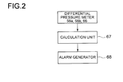
- Fig. 2 is a block diagram illustrating a control system for the reverse osmosis membrane apparatus 10A.
- the detected values by the differential pressure meters 56a, 56b and 66 are sent to a calculation unit 67.
- the calculation unit 67 is configured to calculate the deposition amount of fouling matters from the input detected values. If the calculated deposition amount exceeds a threshold value, the calculation unit sends an alarm signal to an alarm generator 68.
- the alarm generator 68 generates an alarm when receiving the alarm signal.
- the clarified seawater sw is introduced into one or both of the high pressure vessels 12a and 12b, and in a case of maintenance or inspection of one of the high pressure vessels, the clarified seawater sw is introduced into only one of the high pressure vessels.
- the permeate water pw separated by the reverse osmosis membrane element 14a or 14b within the high pressure vessel 12a or 12b is flown out to the permeate water outflow passage 52 via the permeate water outflow passage 34a or 34b, and the permeate water assembly pathway 36.
- the concentrated seawater cs is flown into the high pressure vessel 16 via the concentrated seawater outflow passage 38a or 38b and the concentrated seawater outflow passage 40, and is separated into concentrated seawater and permeate water pw by the reverse osmosis membrane elements 42 in the high pressure vessel 16 sequentially from the upstream side.
- the permeate water pw separated by the reverse osmosis membrane element 42 disposed in the last stage is flown to the permeate water outflow passage 52, and the concentrated seawater cs is flown out from the concentrated seawater outflow passage 54.
- the differential pressure meters 56a, 56b and 66 are monitored, and if the deposition amount of the fouling matters calculated by the calculation unit 67 on the basis of the detected values obtained by the differential pressure meters, the gate valves 58a, 58b, 60a and 60b are operated to stop supplying the clarified seawater sw to stop supplying the clarified seawater sw to the reverse osmosis membrane element of which deposition amount exceeds the threshold value and to start the washing step of the reverse osmosis membrane element.
- a washing fluid a is fed from the washing fluid supplying passage 62 to form a flow of washing fluid contacting the surface of the reverse osmosis membrane of the reverse osmosis membrane element 14a.
- the washing fluid a after washing the reverse osmosis membrane is discharged from the washing fluid discharging passage 64a.
- washing may be carried out in the same manner as above. Since the deposition amount in the reverse osmosis membrane element 42 in the high pressure vessel 16 is small, the required frequency of washing is low; however, if the deposition amount exceeds the threshold value, the washing may be carried out in the same manner as above.
- the reverse osmosis membrane element may be replaced.
- the embodiment since only the reverse osmosis membrane element 14a or 14b disposed in an earlier stage where the fouling amount is large, it is possible to reduce waste of washing chemicals thereby to reduce the cost. Further, since the high pressure vessels 12a and 12b having the reverse osmosis membrane elements 14a and 14b, respectively, of which the frequency of washing is high, it is possible to continue operation of one of the reverse osmosis membrane element in a case where the other one is being washed. Accordingly, it is possible to keep the operation rate of the reverse osmosis membrane apparatus 10A high and to operate the apparatus stably. Further, it is only necessary to open the high pressure vessel 12a or 12b having the reverse osmosis membrane element 14a or 14b therein, it is possible to reduce effort and time required for the washing.
- each of the high pressure vessels 12a and 12b has one reverse osmosis membrane element; however, according to the present invention, the number of the reverse osmosis membrane element is not limited to one, and a plurality of the reverse osmosis membrane elements may be housed in the high pressure vessel 12a or 12b.
- a reverse osmosis membrane apparatus 10B has plurality of high pressure vessels 16 each having therein a plurality of reverse osmosis membrane elements 42 arranged in series, the plurality of high pressure vessels 16 being arranged in parallel with one another and connected to the concentrated seawater outflow passage 40.
- Each of the high pressure vessels 16 and the inner structure thereof are the same as the high pressure vessel 16 according to the first embodiment and the inner structure thereof.
- the permeate water outflow passages 70 respectively connected to the outlet openings 16b of the high pressure vessels 16 are joined with the concentrated seawater assembly pathway 73.
- the concentrated seawater outflow passages 72 respectively connected to the outlet openings 16c of the high pressure vessels 16 are joined with the concentrated seawater assembly pathway 73.
- gate valves 74a and 74b are provided, respectively.
- a bypass pathway 76a branched from the introducing branched passage 18a on an upstream position of the gate valve 58a and connected to the permeate water outflow passage 34a on an upstream position of the gate valve 74a is provided.
- a bypass pathway 76b branched from the introducing branched passage 18b on an upstream position of the gate valve 58b and connected to the permeate water outflow passage 34b on an upstream position of the gate valve 74b is provided.
- a plurality of high pressure vessels 16 are arranged in parallel to each other with respect to each of the concentrated seawater outflow passages 38a and 38b of the high pressure vessels 12a and 12b, whereby it is possible to increase the ability of manufacturing permeate water pw.
- the gate valves 58a, 74a and 60a are closed, and the gate valve 77 is opened.
- the clarified seawater sw is supplied from the bypass pathway 76a to the permeate water outflow passage 34a at a pressure lower than the osmotic pressure generated by the reverse osmosis membrane of the reverse osmosis membrane element 14a by using the pump 20.
- the mixture flow of the permeate water pw and the clarified seawater sw reaches the reverse osmosis membrane of the reverse osmosis membrane element 14a, and only the permeate water pw in the mixture flow is passed through the reverse osmosis membrane.
- the permeate water pw from the permeate water outflow passage 34a is allowed to pass through the reverse osmosis membrane.
- the fouling matters deposited in the reverse osmosis membrane can be peeled off by the permeate water pw passing through the reverse osmosis membrane.
- the permeate water pw passed through the reverse osmosis membrane by the forward osmosis phenomenon is discharged from the washing fluid discharging passage 64a, and the clarified seawater sw supplied to the reverse osmosis membrane element 14a is discharged from the clarified seawater discharging passage 78a.
- washing may be carried out in the same manner.
- the reverse osmosis membrane element may be replaced.
- the embodiment in addition to the effect obtainable by the first embodiment, by using the osmosis pressure of the clarified seawater sw to wash the reverse osmosis membrane element, it is possible to actuate the pump 20 with a reduced power. Further, it enables washing where environmental burden is small without relying on washing ability of chemicals having a strong washing effect.
- the reverse osmosis membrane apparatus 10C has the same configuration as the high pressure vessel 16 illustrated in Fig. 1 or Fig. 3 and the inner structure thereof, and it has a high pressure vessel 16 having a plurality of reverse osmosis membrane elements 42 arranged in series therein.
- a clarified seawater introducing passage 18 is connected to the inlet end of the high pressure vessel 16; a concentrated seawater outflow passage 54 is branched into a branched outflow passages 80a and 80b; the branched outflow passage 80a is connected to an inlet opening 82 of the high pressure vessel 81a; and the branched outflow passage 80b is connected to an inlet opening of the high pressure vessel 81b.
- the high pressure vessels 81a and 81b and the inner structure thereof are the same as the high pressure vessel 12a or 12b and the inner structure according to the first embodiment or the second embodiment.
- the high pressure vessel 81a has one reverse osmosis membrane element 85a therein, and the high pressure vessel 81b has one reverse osmosis membrane element 85b therein.
- Permeate water pw separated by the reverse osmosis membrane elements 85a and 85b from the permeate water outflow passages 86a and 86b, respectively, is flown into a permeate water assembly pathway 88.
- the concentrated seawater cs is flown from outlet openings 84 into concentrated seawater outflow passages 90a and 90b and then joins together into a concentrated seawater assembly pathway 91.
- a differential pressure meter 92a for detecting the differential pressure between the concentrated seawater cs flowing in the branched outflow passage 80a and the concentrated seawater cs flowing in the concentrated seawater outflow passage 90a is provided, and a differential pressure meter 92b for detecting the differential pressure between the concentrated seawater cs flowing in the branched outflow passage 80b and the concentrated seawater cs flowing in the concentrated seawater outflow passage 90b is provided.
- Washing fluid supply passages 94a and 94b are connected to the concentrated seawater outflow passages 90a and 90b, respectively.
- Gate valves 98a and 98b are provided on the branched outflow passages 80a and 80b, respectively, and washing fluid discharging passages 96a and 96b are connected to the branched outflow passages 80a and 80b, respectively.
- Gate valves 99a and 99b are provided on the concentrated seawater outflow passages 90a, and 90b, respectively.
- concentrated seawater cs concentrated sequentially by the plurality of reverse osmosis membrane elements 42 housed in the high pressure vessel 16 is introduced to one or both of the high pressure vessels 81a and 81b.
- the concentrated seawater cs is introduced to the other one.
- the concentrated seawater cs introduced to the last-stage reverse osmosis membrane element 85a or 85b contains metal ions such as Ca and Mg at a high concentration. As such ions may react with e.g. CO 2 dissolved in the seawater to generate scale, the deposition amount of the scale deposited in the reverse osmosis membrane of the reverse osmosis membrane element 85a or 85b may be rapidly increased.
- the washing step is carried out in the same manner as in the above first embodiment.
- the gate valves 98a, 98b, 99a and 99b are operated to stop introducing clarified seawater sw to the reverse osmosis membrane element 85a, and the washing step is carried out.
- washing fluid is supplied from the washing fluid supply passage 94a to form a flow of the washing fluid so that the flow contacts with a surface of the reverse osmosis membrane element 85a, and then the washing fluid is discharged from the washing fluid discharging passage 96a.
- the reverse osmosis membrane element 85b housed in the high pressure vessel 81b is washed, the same operation is carry out.
- the high pressure vessels 81 a and 81b having therein the last-stage reverse osmosis membrane elements 85a and 85b where the fouling amount is large, respectively, are arranged in parallel with each other with regard to the concentrated seawater outflow passage 54, when one of the high pressure vessels is washed, operation of the other one can be continued, whereby it is possible to keep the operating rate of the reverse osmosis membrane apparatus 10C and to operate the apparatus stably. Further, apart from the reverse osmosis membrane elements 42 housed in the high pressure vessel 16, only the reverse osmosis membrane element 85a or 85b of which the frequency of washing is high is washed, whereby it is possible to reduce waste of washing chemicals thereby to reduce the cost.
- the fouling matters deposited in the reverse osmosis membrane are removed by the action of the flow of the washing fluid on the reverse osmosis membrane, whereby it is possible to carry out washing where environmental burden is small without relying on washing ability of chemicals having a strong washing effect such as acids and alkalis.
- clarified seawater sw supplied to the clarified seawater introducing passage 18 by the pump 20 is flown into the high pressure vessel 12a or 12b via the introducing branched passage 18a or 18b.
- the high pressure vessels 12a and 12b have therein the first-stage reverse osmosis membrane elements 14a and 14b, respectively.
- the clarified seawater sw is separated in the high pressure vessel 12a or 12b, and permeate water pw flown into the permeate water outflow passage 34a or 34b is flown out from the permeate water assembly pathway 36 to the permeate water assembly pathway 88.
- Concentrated seawater cs flown out from the high pressure vessel 12a or 12b to the concentrated seawater branched passage 38a or 38b is flown to the concentrated seawater assembly pathway 40.
- a plurality of high pressure vessels 16 are arranged in parallel with respect to the concentrated seawater assembly pathway 40.
- Each of the high pressure vessels 16 has therein a plurality of the reverse osmosis membrane elements 42, i.e. from the second-stage reverse osmosis membrane element to the last stage reverse osmosis membrane element, which are arranged in series.
- the concentrated seawater cs flown to the concentrated seawater outflow passage 40 enters any one of the high pressure vessels 16 to be subjected to membrane separation.
- the permeate water pw flown from the high pressure vessels 16 to the permeate water outflow passage 70 joins in the permeate water assembly pathway 88 via the permeate water assembly pathway 71.
- the high pressure vessels 81a and 81b are arranged in parallel with each other with regard to the concentrated seawater assembly pathway 73.
- the high pressure vessels 81a and 81b have therein the last-stage reverse osmosis membrane elements 85a and 85b, respectively.
- the concentrated seawater cs is flown from the concentrated seawater assembly pathway 73 into the high pressure vessel 81a or 81b to be subjected to membrane separation.
- the permeate water pw flown from the high pressure vessels 81a and 81b to the permeate water outflow passage 86a or 86b is flown out to the permeate water assembly pathway 88.
- the concentrated seawater cs flown from the high pressure vessels 81 and 81b to the concentrated seawater outflow passage 90a and 90b joins in the concentrated seawater assembly pathway 91 and then is discharged.
- the high pressure vessels 12a, 12b and 16 and their inner structures are the same as the high pressure vessels 12a, 12b and 16 and their inner structures used in the first embodiment and the second embodiment.
- the high pressure vessels 81a and 81b and their inner structures are the same as the high pressure vessels 81a and 81b and their inner structures used in the third embodiment.
- the high pressure vessel 12a is provided with a differential pressure meter 56a for detecting the differential pressure between the pressure of the clarified seawater sw flowing in the introducing branched passage 18a and the pressure of the concentrated seawater flowing in the concentrated seawater outflow passage 38a.
- the high pressure vessel 12b is provided with a differential pressure meter 56b for detecting the differential pressure between the pressure of the clarified seawater sw flowing in the introducing branched passage 18b and the pressure of the concentrated seawater flowing in the concentrated seawater outflow passage 38b.
- each of the plurality of the high pressure vessels 16 is provided with a differential pressure meter 66 for detecting the differential pressure between the pressure of the concentrated seawater cs flowing in the concentrated seawater assembly pathway 40 and the pressure of the concentrated seawater flowing in the concentrated seawater discharging passage 70.
- the high pressure vessel 81a is provided with a differential pressure meter 92a for detecting the difference between the pressure of the concentrated seawater cs flowing in the concentrated seawater assembly pathway 73 and the pressure of the concentrated seawater cs flowing in the concentrated seawater outflow passage 90a.
- the high pressure vessel 81b is provided with a differential pressure meter 92b for detecting the difference between the pressure of the concentrated seawater cs flowing in the concentrated seawater assembly pathway 73 and the pressure of the concentrated seawater cs flowing in the concentrated seawater outflow passage 90b.
- gate valves 74a and 74b are provided on the permeate water outflow passages 34a and 34b, respectively, to which permeate water pw is flown from the high pressure vessels 12a and 12b.
- bypass pathway 76a branched from the introducing branched passage 18a on an upstream position of the gate valve 58a and connected to the permeate water outflow passage 34a on an upstream position of the gate valve 74a is provided.
- bypass pathway 76b branched from the introducing branched passage 18b on an upstream position of the gate valve 58b and connected to the permeate water outflow passage 34b on an upstream position of the gate valve 74b is provided.
- Gate valves 77a and 77b are provided on the bypass pathway 76a and 76b, respectively, and the permeate water outflow passages 32a and 34b are provided with clarified seawater discharging passages 78a and 78b, respectively, for discharging clarified seawater sw supplied as a washing fluid in the washing step.
- Washing fluid supply passages 94a and 94b are connected to the concentrated seawater outflow passages 90a and 90b, and gate valves 99a and 99b are provided on the concentrated seawater outflow passages 90a and 90b.
- the branched outflow passages 80a and 80b have washing fluid discharging passages 96a and 96b, respectively, which are branched therefrom, and are provided with gate valves 98a and 98b, respectively.
- the mixture flow of the permeate water pw and the clarified seawater sw reaches the reverse osmosis membrane of the reverse osmosis membrane element 14a, and only the permeate water pw in the mixture flow is passed through the reverse osmosis membrane.
- the permeate water pw from the permeate water outflow passage 34a is allowed to pass through the reverse osmosis membrane.
- the fouling matters deposited in the reverse osmosis membrane can be peeled off by the permeate water pw passing through the reverse osmosis membrane.
- the permeate water pw passed through the reverse osmosis membrane by the forward osmosis phenomenon is discharged from the washing fluid discharging passage 64a, and the clarified seawater sw supplied to the reverse osmosis membrane element 14a is discharged from the clarified seawater discharging passage 78a.
- washing may be carried out in the same manner.
- the gate valves 98a, 98b, 99a and 99b are operated to stop introducing clarified seawater sw to the reverse osmosis membrane element 81a, and the washing step is carried out.
- washing fluid a is supplied from the washing fluid supply passage 94a to form a flow of the washing fluid so that the flow contacts with a surface of the reverse osmosis membrane element 85a, and then the washing fluid is discharged from the washing fluid discharging passage 96a.
- the reverse osmosis membrane element 85b housed in the high pressure vessel 81b is washed, the same operation is carry out.
- washing may be carried out according to the method for the high pressure vessels 12a and 12b or the method for the high pressure vessels 81a and 81b.
- the high pressure vessels 12a and 12b having therein the first-stage reverse osmosis membrane elements 14a and 14b where the fouling amount is large, respectively are arranged in parallel with each other with regard to the clarified seawater introducing passage 18, and the high pressure vessels 81a and 81b having therein the last-stage reverse osmosis membrane elements 85a and 85b, respectively, are arranged in parallel with each other with regard to the concentrated seawater assembly pathway 73, when one of the high pressure vessels is washed, operation of the other one can be continued. Accordingly, it is possible to keep the operating rate of the reverse osmosis membrane apparatus 10D and to operate the apparatus stably.
- washing of the reverse osmosis membrane element is carried out by using osmosis pressure of the clarified seawater sw in the high pressure vessel 12a or 12b, it is possible to actuate the pump 20 with a reduced power. Further, it is possible to carry out washing where environmental burden is small without using chemicals having a strong washing effect as the washing fluid.
- the fouling matters deposited in the reverse osmosis membrane are removed by the action of the flow of the washing fluid on the reverse osmosis membrane, whereby it is possible to carry out washing where environmental burden is small without relying on washing ability of chemicals having a strong washing effect such as acids and alkalis.
- a spiral-type reverse osmosis membrane element is used; however, in the present invention, a flat membrane-type reverse osmosis membrane element may be alternatively used.
Landscapes
- Chemical & Material Sciences (AREA)
- Engineering & Computer Science (AREA)
- Water Supply & Treatment (AREA)
- Chemical Kinetics & Catalysis (AREA)
- Nanotechnology (AREA)
- Life Sciences & Earth Sciences (AREA)
- Hydrology & Water Resources (AREA)
- Environmental & Geological Engineering (AREA)
- Organic Chemistry (AREA)
- Separation Using Semi-Permeable Membranes (AREA)
Abstract
Description
- The present invention relates to a reverse osmosis membrane apparatus and a method of operating a reverse osmosis membrane which enables reduction of time and effort required for washing or replacement of a reverse osmosis membrane and stable continuous operation of the apparatus.
- For production of fresh water from seawater or for production of clean water from river or lake water, reverse osmosis membrane apparatuses having a reverse osmosis membrane module, for example, are used. In a reverse osmosis membrane apparatus, a to-be-treated water (clarified water) produced by subjecting e.g. sea, river or lake water as raw water to pretreatment such as sterilization treatment of adding a fungicide into intake sea, river or lake water or a treatment of removing impurities by using e.g. a sand filter, is used. The to-be-treated water is pressurized to have a pressure of about 6.0 MPa by a high pressure pump, for example, and is supplied to a reverse osmosis membrane module, and the to-be-treated water is permitted to pass through a reverse osmosis membrane by reverse osmosis effect by the reverse osmosis membrane module to obtain permeate water to be production water.
- A reverse osmosis membrane module is usually composed of a plurality of reverse osmosis membrane elements. An example of the reverse osmosis membrane elements is a spiral-type reverse osmosis membrane element having a structure where a sac-like reverse osmosis membrane having a flow path material therein is spirally wound via a mesh spacer around a center pipe in which permeate water is collected, and a brine seas is provided at an end of the outer peripheral surface, as disclosed in Patent Document 1. Another example of the reverse osmosis membrane elements is a flat membrane-type reverse osmosis membrane element having stacked a plurality of flat sheets of reverse osmosis membrane.
- A reverse osmosis membrane module usually has a high pressure vessel and a plurality of reverse osmosis membrane elements arranged in series in the high pressure vessel, and to-be-treated (clarified water) is separated with reverse osmosis membrane elements sequentially from one on the most upstream side into permeate water and concentrated water containing saline matters and impurities to obtain permeate water by each of the reverse osmosis membrane elements. The concentrated water separated from the permeate water by each of the reverse osmosis membrane element is further separated into permeate water and concentrated water by a later stage element of the reverse osmosis membrane elements. Therefore, the salinity and concentration of impurities of concentrated water are higher at relatively downstream side.
Patent Document 2 discloses a construction where a plurality of high pressure vessels each having a spiral-type reverse osmosis membrane element therein, is connected to a to-be-treated water introducing passage and arranged in parallel. -
Fig. 6 shows an example of a construction of a reverse osmosis membrane module having a high pressure vessel and spiral-type reverse osmosis membrane elements arranged in series therein, which is disclosed in Patent Document 1. InFig. 6 , the reverseosmosis membrane apparatus 100 comprises ahigh pressure vessel 102 and four to eight reverseosmosis membrane elements 104 arranged in series in thehigh pressure vessel 102. To-be-treated water tw is supplied at a high pressure to an inlet opening 102a of thehigh pressure vessel 102 from a to-be-treatedwater supply passage 114. If it is assumed that among the plurality of reverse osmosis membrane elements arranged in series, a reverse osmosis membrane on an upstream side of the flow of the to-be-treated water tw is an earlier stage element and a reverse osmosis membrane on a downstream side of the flow of the to-be-treated water tw is a later stage element, the to-be-treated water tw is flown into an inlet end of the earliest-stage element of the reverseosmosis membrane elements 104 and separated into permeate water pw and concentrated water cs by the reverse osmosis membrane in the reverse osmosis membrane element 104a. - The permeate water pw is flown into the
center pipe 106, and the concentrated water cw is flown out from the outlet of the earliest-stage reverse osmosis membrane element. The inlet of thecenter pipe 106 of the earliest-stage reverse osmosis membrane element 104a is obstructed with anend cap 108. Thecenter pipe 106 of each of the reverseosmosis membrane elements 104 is connected with aconnector 110. Accordingly, the permeate water pw from each of the reverse osmosis membrane elements joins together and is discharged from an outlet opening 102b of thehigh pressure vessel 102 to a permeatewater outflow passage 116. - As the interior of the
high pressure vessel 102 is partitioned withbrine seals 112 provided on outer peripheral surface of each of the reverseosmosis membrane elements 104, the concentrated water cw flown out of each of the reverseosmosis membrane elements 104 is flown into the later stage element of the reverse osmosis membrane elements as to-be-treated water without going past the reverse osmosis membrane element of the later stage. The concentrated water cw is thereby permeated sequentially with the reverse osmosis membrane elements. The concentrated water cw discharged from the reverseosmosis membrane element 104 in the last stage is discharged from an outlet opening 102c formed at the outlet end of thehigh pressure vessel 102 to a concentratedwater discharging passage 118. - A
differential pressure meter 120 for detecting the differential pressure between the pressure of the to-be-treated water tw flowing in the to-be-treatedwater introducing passage 114 and the pressure of the concentrated water cw flowing in the concentratedwater discharging passage 118 is provided. - The method of washing the reverse
osmosis membrane element 100 was such that when the detected value by thedifferential pressure meter 120 exceeds the threshold, deposition amount of fouling matters such as hardly-soluble ingredients, high molecular solute, colloids, or tiny solid materials deposited in the reverse osmosis membranes is defined as exceeding the threshold limit, and then the operation of the reverseosmosis membrane apparatus 100 was stopped, and washing was carried out. When the differential pressure between the to-be-treated water tw flowing in the to-be-treatedwater introducing passage 114 and the permeate water pw flowing in the permeatewater outflow passage 116 exceeds the threshold, the same washing method as described above may be applied. Accordingly, the difference in pressure between the to-be-treated water tw flowing in the to-be-treatedwater introducing passage 114 and the permeate water pw flowing in the permeatewater outflow passage 116 may be detected. -
- Patent Document 1:
JP 2001-300264 A - Patent Document 2:
JP 2001-191071 A - Among the reverse osmosis membrane elements arranged in series, deposition of fouling matters in the reverse osmosis membrane is more concentrated in the reverse osmosis membrane element disposed in the earlier stage. On the other hand, in a case where the to-be-treated water is seawater containing saline matters, the concentration of metal ions such as Ca or Mg in the concentrated seawater is higher in the reverse osmosis membrane element disposed in the later stage. Since such metal ions may react with e.g. CO2 dissolved in the seawater to generate scale, the deposition amount of scale deposited in the reverse osmosis membrane is larger in the reverse osmosis membrane element disposed in the later stage. Although such scale may be removed by feeding chemicals such as citric acid or HCl, there is a problem such that the amount of the chemicals and thereby the cost tend to be increased.
- As described above, in a conventional washing method, the plurality of reverse osmosis membrane elements arranged in series in a high pressure vessel are washed at once. Accordingly, reverse osmosis membrane elements in the intermediate part having only small amount of fouling (clogging) would be washed excessively, and thus there is a problem such that waste of time and chemicals for washing becomes large. In addition, although damage to the reverse osmosis membrane by washing is inevitable, such the reverse osmosis membrane would be damaged excessively. Further, in monitoring using a differential pressure meter, since the differential pressure of accumulation of the plurality of the reverse osmosis membrane elements, the sensitivity to detect the differential pressure is not high. Thus, a proper timing for washing could be overlooked.
- Further, in a case where fouling matters deposited in the reverse osmosis membrane cannot be completely removed, the reverse osmosis membrane element needs to be replaced. However, since it is necessary to open the high pressure vessel having a plurality of reverse osmosis membrane elements therein to carry out replacement, there is a problem that much time and effort are required.
- In view of the above problems, an object of the present invention is, in a reverse osmosis membrane apparatus having a high pressure vessel and a plurality of reverse osmosis membrane elements arranged in series in the high pressure vessel where to-be-treated water (clarified water) obtained by subjecting raw water to pretreatment is separated into concentrated water and permeate water with the reverse osmosis membrane elements sequentially from the first stage element to obtain permeate water, to reduce time and effort required for washing of the reverse osmosis membrane apparatus and thereby to increase operating rate and to enable stable operation of the reverse osmosis membrane apparatus.
- In order to accomplish the object, the reverse osmosis membrane apparatus according to the present invention comprises:
- a plurality of first high pressure vessels arranged in parallel with each other and connected to an introducing passage of the to-be-treated water and having first reverse osmosis membrane elements therein, respectively, each of the first reverse osmosis membrane elements being, among the plurality of reverse osmosis membrane elements arranged in series, a reverse osmosis membrane element in an earlier stage (disposed on an upstream side of a flow of the to-be-treated water), in which fouling is deposited in a relatively large amount, or a reverse osmosis membrane element in a later stage (disposed on a downstream side of the flow of the to-be-treated water);
- a second pressure vessel arranged in series in relation to the first high pressure vessels and having therein second reverse osmosis membrane elements other than the first reverse osmosis membrane elements among the plurality of reverse osmosis membrane elements, the second reverse osmosis membrane elements being arranged in series;
- a deposition amount detector for detecting a deposition amount of fouling matters deposited in a reverse osmosis membrane of the first reverse osmosis membrane elements; and
- a flow path switching device configured, when the deposition amount of the fouling matters deposited in one of the first reverse osmosis membrane elements exceeds a threshold value, to stop introducing the to-be-treated water into the first high pressure vessel having the one of the first reverse osmosis membrane elements therein and to permit the to-be-treated water to flow into the other of the first reverse osmosis membrane elements arranged in parallel with the one of the first reverse osmosis membrane elements.
- According to the present invention, among the plurality of reverse osmosis membrane elements arranged in series, the first reverse osmosis membrane elements which are disposed in the earlier stage where the amount of fouling is relatively large or which are disposed in the later stage, are accommodated in a high pressure vessel other than a high pressure vessel which accommodates the other reverse osmosis membrane elements. The deposition amount of fouling matters only in the first reverse osmosis membrane elements is detected, and when the deposition amount exceeds the threshold value, washing or replacement is carried out only for the first reverse osmosis membrane elements. Since the frequency of washing or replacement for the second reverse osmosis membrane elements is low, washing or replacement can be separately carried out when needed.
- According to the present invention, by arranging in parallel with each other the first high pressure vessels each having only the reverse osmosis membrane element disposed in the earlier stage where the amount of fouling is relatively large or disposed in the later stage, even if one of the reverse osmosis membrane element is stopped for maintenance such as washing or replacement, it is possible to continue the operation by supplying the to-be-treated water to the reverse osmosis membrane element of the other of the first high pressure vessel. Further, by setting a timing for washing or replacement with regard to the reverse osmosis membrane element disposed in the earlier stage or in the later stage independently from the second reverse osmosis membrane elements, it is possible to reduce waste of washing chemicals thereby to reduce the cost. Further, when a reverse osmosis membrane element of which fouling deposition amount is large is needed to be washed or replaced, it is only necessary to open the high pressure vessel which accommodates the first reverse osmosis membrane element, whereby it is possible to reduce effort for washing or replacement and to reduce the time required for washing or replacement.
- In an embodiment of the present invention, the reverse osmosis membrane apparatus may comprise: a washing fluid supplying part for supplying the reverse osmosis membrane of the first reverse osmosis membrane element with washing fluid; and a washing fluid discharging passage for discharging the washing fluid after washing of the reverse osmosis membrane of the first reverse osmosis membrane element. It is thereby possible to peel off the fouling matters deposited in the reverse osmosis membrane by peeling action of the washing fluid on the reverse osmosis membrane. Accordingly, it enables washing where environmental burden is small without relying on washing ability of chemicals having a strong washing effect such as acids and alkalis.
- In such a case, a flow of washing fluid contacting with the reverse osmosis membrane along the reverse osmosis membrane may be formed, or, a flow passing through the reverse osmosis membrane by the flow of the washing fluid may be formed. The flow of the washing fluid along the reverse osmosis membrane can be formed by a flow of the washing fluid flowing between the to-be-treated water introducing passage and the concentrated water discharging passage, and the flow of the washing fluid passing through the reverse osmosis membrane can be formed by a flow of the washing fluid introduced from the permeate water passage to the reverse osmosis membrane, for example.
- In an embodiment, the deposition amount detector may comprise: a differential pressure detector for detecting a differential pressure between a pressure of the to-be-treated water flowing in a to-be-treated introducing passage of the first reverse osmosis membrane element and a pressure of the concentrated water flowing in a concentrated water discharging passage; and a deposition amount calculation device for calculating the deposition amount of the fouling matters from a detected value by the differential pressure detector. According to this configuration, it is possible to accurately detect the deposition amount of the fouling matters in the first reverse osmosis membrane element where the fouling deposition amount is large, whereby it is possible to accurately determine the timing for washing or replacement of the first reverse osmosis membrane element.
- In an embodiment of the present invention, the reverse osmosis membrane apparatus may further comprise an alarm generator for generating an alarm when the deposition amount of the fouling matters detected by the deposition amount detector exceeds a threshold value. It is thereby possible to know without delay the timing when washing or replacement of the first reverse osmosis membrane is required.
- In an embodiment of the present invention, a plurality of the second high pressure vessels may be arranged in parallel with each other and connected to a concentrated water outflow passage provided for the first high pressure vessel. It is thereby possible to increase the manufacturing ability of permeate water or to make the manufacturing ability of permeate water variable, and to wash or replace the reverse osmosis membrane element accommodated in one of the second pressure vessels without stopping the reverse osmosis membrane apparatus.
- The method of operating the reverse osmosis membrane apparatus according to an embodiment of the present invention comprises: a flow path switching step of, when the alarm is generated by the alarm generator, stopping introduction of the to-be-treated water to the one of the first reverse osmosis membrane elements having deposited fouling matters of which the deposition amount exceeds the threshold value, and introducing the to-be-treated water into the other of the first reverse osmosis membrane elements by the flow path switching device; and a washing step of supplying washing fluid from the washing fluid supplying part, peeling off the fouling matters deposited in the reverse osmosis membrane of the first reverse osmosis membrane element by flow of the washing fluid, and then discharging the washing fluid from the washing fluid discharging passage. According to the method, in addition to the above effect obtained by the apparatus according to the present invention, it is possible to know the timing when washing of the first reverse osmosis membrane element is required without delay by the alarm signal.
- In an embodiment, in the washing step, as the washing fluid, the to-be-treated water may be supplied to the first reverse osmosis membrane element via a permeate water passage at a pressure lower than an osmotic pressure caused by the reverse osmosis membrane of the first reverse osmosis membrane element, and the permeate water is permitted to flow backward from the permeate water passage through the reverse osmosis membrane element to the to-be-treated water side by a pressure difference between the osmotic pressure of the to-be-treated water and a pressure of the permeate water having no osmotic pressure, utilizing the difference in the salinity between the permeate water and the to-be-treated water. It thereby enables energy-saving washing with a small environmental burden with a low power without using chemicals having a strong washing effect as the washing fluid.
- According to the preset invention, a plurality of high pressure vessels have therein only the first reverse osmosis membrane elements in which the fouling deposition amount is large, respectively, and the plurality of high pressure vessels are arranged in parallel with each other and connected to the to-be-treated water introducing passage, whereby it is possible to reduce the effort and time required to wash the reverse osmosis membrane apparatus and to increase the operation rate of the reverse osmosis membrane apparatus to enable stable operation of the apparatus.
-
-
Fig. 1 is a flow diagram of a reverse osmosis membrane apparatus according to a first embodiment of the present invention. -
Fig. 2 is a block diagram illustrating a control system for the reverse osmosis membrane apparatus according to the first embodiment. -
Fig. 3 is a flow diagram of a reverse osmosis membrane apparatus according to a second embodiment of the present invention. -
Fig. 4 is a flow diagram of a reverse osmosis membrane apparatus according to a third embodiment of the present invention. -
Fig. 5 is a flow diagram of a reverse osmosis membrane apparatus according to a fourth embodiment of the present invention. -
Fig. 6 is a longitudinal sectional view of a conventional reverse osmosis membrane apparatus. - Embodiments of the present invention will now be described in detail with reference to the accompanying drawings. It is intended, however, that unless particularly specified, dimensions, materials, shapes, relative positions and the like of components described in the embodiments shall be interpreted as illustrative only and not limitative of the scope of the present invention.
- A first embodiment of the present invention will now be described with reference to
Fig. 1 . This embodiment is an example of a reverse osmosis membrane apparatus applied to a seawater desalination plant. To-be-treated water used in this embodiment illustrated inFig. 1 is obtained by subjecting introduced raw seawater to pretreatment of sterilization and removal of relatively large foreign substances such as dusts and microbes. The clarified seawater sw subjected to the pretreatment is used as the to-be-treated water. The reverseosmosis membrane apparatus 10A has twohigh pressure vessels passage 18 of clarifiedseawater 18 via introducing branchedpassages 18a and 18b, respectively. Inside thehigh pressure vessels osmosis membrane elements - Clarified seawater sw is supplied to an inlet opening 22 of the
high pressure vessel passage 18a or 18b at a high pressure by apump 20 provided on the clarifiedseawater introducing passage 18. Clarified water sw is flown into the reverseosmosis membrane element osmosis membrane element high pressure vessels high pressure vessels - The permeate water pw is flown into a
center pipe 28, and the concentrated seawater cs is flown out from an outlet end of the reverseosmosis membrane element osmosis membrane element end cap 30. Thecenter pipe 28 is connected to anoutlet opening 24 of thehigh pressure vessel connector 32, and the permeate water pw is flown out from thecenter pipe 28 via the outlet opening 24 to a permeatewater outflow passages water outflow passages water assembly pathway 36. The interior of thehigh pressure vessel brine seal 31 provided on outer peripheral surface of the reverseosmosis membrane element - The concentrated seawater cs is flown out from the outlet end of the reverse
osmosis membrane element outlet opening 26 is formed at the outlet end of thehigh pressure vessel outlet opening 26 is connected to a concentratedseawater outflow passage seawater outflow passages seawater assembly pathway 40, and the concentratedseawater assembly pathway 40 is connected to aninlet opening 16a of ahigh pressure vessel 16. The configuration of thehigh pressure vessel 16 and its interior is basically the same as thehigh pressure vessel 102 and its interior shown inFig. 6 . - That is, in the
high pressure vessel 16, a plurality of reverseosmosis membrane elements 42 are arranged in series. Permeate water pw from each of the reverse osmosis membrane elements is flown into acenter pipe 44 which is connected to another center pipe with aconnector 46, and the permeate water pw from each of the reverse osmosis membrane elements joins in thecenter pipe 44. Acenter pipe 44 is connected to anoutlet opening 16b of thehigh pressure vessel 16 with aconnector 46. The permeate water pw from each of the reverse osmosis membrane elements is flown out from the outlet opening 16b to the permeatewater outflow passage 52. The permeatewater assembly pathway 36 is connected to the permeatewater outflow passage 52. The front end of thecenter pipe 44 of the earliest-stage reverseosmosis membrane element 42 is obstructed with anend cap 48, and the interior of thehigh pressure vessel 16 is partitioned with abrine seal 50 provided on outer peripheral surface of each of the reverse osmosis membrane elements. - Concentrated seawater cs concentrated by the reverse
osmosis membrane element seawater assembly pathway 40 into the inside of thehigh pressure vessel 16. The concentrated seawater cs flown into thehigh pressure vessel 16 is firstly separated into concentrated seawater cs and permeate water pw with the earliest-stage reverseosmosis membrane element 42. This permeate water pw is flown into thecenter pipe 46, while the concentrated seawater cs is flown from the outlet end of the earliest-stage reverseosmosis membrane element 42 and then is concentrated with each of the subsequent reverse osmosis membrane elements sequentially. Anoutlet opening 16c is formed at the outlet end of thehigh pressure vessel 16, and a concentratedseawater outflow passage 54 is connected to theoutlet opening 16c. The concentrated seawater cs separated by the last-stage reverseosmosis membrane element 42 is flown out from theoutlet opening 16c to the concentratedseawater outflow passage 54. - In the
high pressure vessel 12a, provided is adifferential pressure meter 56a for detecting a pressure difference between the clarified seawater sw flowing in the introducing branched passage 18a and the concentrated seawater cs flowing in the concentratedseawater outflow passage 34a. In thehigh pressure vessel 12b, provided is adifferential pressure meter 56b for detecting a pressure difference between the clarified seawater sw flowing in the introducing branchedpassage 18b and the concentrated seawater cs flowing in the concentratedseawater outflow passage 38b. In the introducing branchedpassages 18a and 18b and in the concentratedseawater outflow passages gate valves - To the concentrated
seawater outflow passages fluid supplying passages passages 18a and 18b, washingfluid discharging passages high pressure vessel 16, adifferential pressure meter 66 for detecting a differential pressure between the concentrated seawater cs flowing in the concentratedseawater outflow passage 40 and the concentrated seawater cs flowing in the concentratedseawater outflow passage 54. -
Fig. 2 is a block diagram illustrating a control system for the reverseosmosis membrane apparatus 10A. The detected values by thedifferential pressure meters calculation unit 67. Thecalculation unit 67 is configured to calculate the deposition amount of fouling matters from the input detected values. If the calculated deposition amount exceeds a threshold value, the calculation unit sends an alarm signal to analarm generator 68. Thealarm generator 68 generates an alarm when receiving the alarm signal. - With such a configuration, when the reverse
osmosis membrane apparatus 10A is operated, by operating thegate valves high pressure vessels osmosis membrane element high pressure vessel water outflow passage 52 via the permeatewater outflow passage water assembly pathway 36. The concentrated seawater cs is flown into thehigh pressure vessel 16 via the concentratedseawater outflow passage seawater outflow passage 40, and is separated into concentrated seawater and permeate water pw by the reverseosmosis membrane elements 42 in thehigh pressure vessel 16 sequentially from the upstream side. - The permeate water pw separated by the reverse
osmosis membrane element 42 disposed in the last stage is flown to the permeatewater outflow passage 52, and the concentrated seawater cs is flown out from the concentratedseawater outflow passage 54. During operation, thedifferential pressure meters calculation unit 67 on the basis of the detected values obtained by the differential pressure meters, thegate valves - For example, in the washing step of washing the reverse
osmosis membrane element 14a, a washing fluid a is fed from the washing fluid supplying passage 62 to form a flow of washing fluid contacting the surface of the reverse osmosis membrane of the reverseosmosis membrane element 14a. The washing fluid a after washing the reverse osmosis membrane is discharged from the washingfluid discharging passage 64a. In a case of the reverseosmosis membrane element 14b, washing may be carried out in the same manner as above. Since the deposition amount in the reverseosmosis membrane element 42 in thehigh pressure vessel 16 is small, the required frequency of washing is low; however, if the deposition amount exceeds the threshold value, the washing may be carried out in the same manner as above. - When the fouling matters are not completely removed despite washing, the reverse osmosis membrane element may be replaced.
- According to the embodiment, since only the reverse
osmosis membrane element high pressure vessels osmosis membrane elements osmosis membrane apparatus 10A high and to operate the apparatus stably. Further, it is only necessary to open thehigh pressure vessel osmosis membrane element - Further, the flow of the washing fluid has action on the reverse osmosis membrane, whereby it is possible peel off the fouling matters deposited in the reverse osmosis membrane. Accordingly, it is possible to carry out washing where environmental burden is small without relying on washing ability of chemicals having a strong washing effect such as acids and alkalis. In the embodiment, each of the
high pressure vessels high pressure vessel - A second embodiment of the present invention will now be described with reference to
Fig. 3 . In contrast to the first embodiment, a reverseosmosis membrane apparatus 10B according to the second embodiment has plurality ofhigh pressure vessels 16 each having therein a plurality of reverseosmosis membrane elements 42 arranged in series, the plurality ofhigh pressure vessels 16 being arranged in parallel with one another and connected to the concentratedseawater outflow passage 40. Each of thehigh pressure vessels 16 and the inner structure thereof are the same as thehigh pressure vessel 16 according to the first embodiment and the inner structure thereof. The permeatewater outflow passages 70 respectively connected to theoutlet openings 16b of thehigh pressure vessels 16 are joined with the concentratedseawater assembly pathway 73. The concentratedseawater outflow passages 72 respectively connected to theoutlet openings 16c of thehigh pressure vessels 16 are joined with the concentratedseawater assembly pathway 73. - In the permeate
water outflow passages high pressure vessels gate valves bypass pathway 76a branched from the introducing branched passage 18a on an upstream position of thegate valve 58a and connected to the permeatewater outflow passage 34a on an upstream position of thegate valve 74a is provided. Abypass pathway 76b branched from the introducing branchedpassage 18b on an upstream position of thegate valve 58b and connected to the permeatewater outflow passage 34b on an upstream position of thegate valve 74b is provided. In thebypass pathway gate valves seawater discharging passages water outflow passages - In this embodiment, a plurality of
high pressure vessels 16 are arranged in parallel to each other with respect to each of the concentratedseawater outflow passages high pressure vessels osmosis membrane element 14a housed in thehigh pressure vessel 12a is washed, for example, thegate valves bypass pathway 76a to the permeatewater outflow passage 34a at a pressure lower than the osmotic pressure generated by the reverse osmosis membrane of the reverseosmosis membrane element 14a by using thepump 20. - By such a configuration, the mixture flow of the permeate water pw and the clarified seawater sw reaches the reverse osmosis membrane of the reverse
osmosis membrane element 14a, and only the permeate water pw in the mixture flow is passed through the reverse osmosis membrane. By the pressure difference between the clarified seawater sw with an osmosis pressure generated at this time and the permeate water pw having no osmosis pressure, the permeate water pw from the permeatewater outflow passage 34a is allowed to pass through the reverse osmosis membrane. The fouling matters deposited in the reverse osmosis membrane can be peeled off by the permeate water pw passing through the reverse osmosis membrane. - The permeate water pw passed through the reverse osmosis membrane by the forward osmosis phenomenon is discharged from the washing
fluid discharging passage 64a, and the clarified seawater sw supplied to the reverseosmosis membrane element 14a is discharged from the clarifiedseawater discharging passage 78a. In a case of washing the reverseosmosis membrane element 14b housed in thehigh pressure vessel 12b, washing may be carried out in the same manner. When the fouling matters cannot be removed despite washing the reverse osmosis membrane element, the reverse osmosis membrane element may be replaced. - According to the embodiment, in addition to the effect obtainable by the first embodiment, by using the osmosis pressure of the clarified seawater sw to wash the reverse osmosis membrane element, it is possible to actuate the
pump 20 with a reduced power. Further, it enables washing where environmental burden is small without relying on washing ability of chemicals having a strong washing effect. - A third embodiment of the present invention will now be described with reference to
Fig. 4 . The reverseosmosis membrane apparatus 10C has the same configuration as thehigh pressure vessel 16 illustrated inFig. 1 orFig. 3 and the inner structure thereof, and it has ahigh pressure vessel 16 having a plurality of reverseosmosis membrane elements 42 arranged in series therein. A clarifiedseawater introducing passage 18 is connected to the inlet end of thehigh pressure vessel 16; a concentratedseawater outflow passage 54 is branched into a branchedoutflow passages outflow passage 80a is connected to aninlet opening 82 of thehigh pressure vessel 81a; and the branchedoutflow passage 80b is connected to an inlet opening of thehigh pressure vessel 81b. Thehigh pressure vessels high pressure vessel - The
high pressure vessel 81a has one reverseosmosis membrane element 85a therein, and thehigh pressure vessel 81b has one reverseosmosis membrane element 85b therein. Permeate water pw separated by the reverseosmosis membrane elements water outflow passages water assembly pathway 88. The concentrated seawater cs is flown fromoutlet openings 84 into concentratedseawater outflow passages seawater assembly pathway 91. Adifferential pressure meter 92a for detecting the differential pressure between the concentrated seawater cs flowing in the branchedoutflow passage 80a and the concentrated seawater cs flowing in the concentratedseawater outflow passage 90a is provided, and adifferential pressure meter 92b for detecting the differential pressure between the concentrated seawater cs flowing in the branchedoutflow passage 80b and the concentrated seawater cs flowing in the concentratedseawater outflow passage 90b is provided. - Washing
fluid supply passages seawater outflow passages Gate valves outflow passages fluid discharging passages outflow passages Gate valves seawater outflow passages - In such a configuration, concentrated seawater cs concentrated sequentially by the plurality of reverse
osmosis membrane elements 42 housed in thehigh pressure vessel 16 is introduced to one or both of thehigh pressure vessels - As described above, the concentrated seawater cs introduced to the last-stage reverse
osmosis membrane element osmosis membrane element - During operation of the reverse
osmosis membrane apparatus 10C, if the detected value of thedifferential pressure meter differential pressure meter 92a exceeds the threshold value, thegate valves osmosis membrane element 85a, and the washing step is carried out. - In the washing step, firstly, washing fluid is supplied from the washing
fluid supply passage 94a to form a flow of the washing fluid so that the flow contacts with a surface of the reverseosmosis membrane element 85a, and then the washing fluid is discharged from the washingfluid discharging passage 96a. In a case where the reverseosmosis membrane element 85b housed in thehigh pressure vessel 81b is washed, the same operation is carry out. - According to this embodiment, as the
high pressure vessels osmosis membrane elements seawater outflow passage 54, when one of the high pressure vessels is washed, operation of the other one can be continued, whereby it is possible to keep the operating rate of the reverseosmosis membrane apparatus 10C and to operate the apparatus stably. Further, apart from the reverseosmosis membrane elements 42 housed in thehigh pressure vessel 16, only the reverseosmosis membrane element - Further, it is only necessary to open the
high pressure vessel osmosis membrane element - Further, the fouling matters deposited in the reverse osmosis membrane are removed by the action of the flow of the washing fluid on the reverse osmosis membrane, whereby it is possible to carry out washing where environmental burden is small without relying on washing ability of chemicals having a strong washing effect such as acids and alkalis.
- A fourth embodiment of the present invention will now be described with reference to
Fig. 5 . In the reverseosmosis membrane apparatus 10D in the embodiment, clarified seawater sw supplied to the clarifiedseawater introducing passage 18 by thepump 20 is flown into thehigh pressure vessel passage 18a or 18b. Thehigh pressure vessels osmosis membrane elements high pressure vessel water outflow passage water assembly pathway 36 to the permeatewater assembly pathway 88. - Concentrated seawater cs flown out from the
high pressure vessel passage seawater assembly pathway 40. A plurality ofhigh pressure vessels 16 are arranged in parallel with respect to the concentratedseawater assembly pathway 40. Each of thehigh pressure vessels 16 has therein a plurality of the reverseosmosis membrane elements 42, i.e. from the second-stage reverse osmosis membrane element to the last stage reverse osmosis membrane element, which are arranged in series. The concentrated seawater cs flown to the concentratedseawater outflow passage 40 enters any one of thehigh pressure vessels 16 to be subjected to membrane separation. The permeate water pw flown from thehigh pressure vessels 16 to the permeatewater outflow passage 70 joins in the permeatewater assembly pathway 88 via the permeatewater assembly pathway 71. - The concentrated seawater flown out from any of the
high pressure vessels 16 to the concentratedseawater outflow passage 72 joins in the concentratedseawater assembly pathway 73. Thehigh pressure vessels seawater assembly pathway 73. Thehigh pressure vessels osmosis membrane elements seawater assembly pathway 73 into thehigh pressure vessel high pressure vessels water outflow passage water assembly pathway 88. The concentrated seawater cs flown from thehigh pressure vessels 81 and 81b to the concentratedseawater outflow passage seawater assembly pathway 91 and then is discharged. - The
high pressure vessels high pressure vessels high pressure vessels high pressure vessels - The
high pressure vessel 12a is provided with adifferential pressure meter 56a for detecting the differential pressure between the pressure of the clarified seawater sw flowing in the introducing branched passage 18a and the pressure of the concentrated seawater flowing in the concentratedseawater outflow passage 38a. Thehigh pressure vessel 12b is provided with adifferential pressure meter 56b for detecting the differential pressure between the pressure of the clarified seawater sw flowing in the introducing branchedpassage 18b and the pressure of the concentrated seawater flowing in the concentratedseawater outflow passage 38b. - Further, each of the plurality of the
high pressure vessels 16 is provided with adifferential pressure meter 66 for detecting the differential pressure between the pressure of the concentrated seawater cs flowing in the concentratedseawater assembly pathway 40 and the pressure of the concentrated seawater flowing in the concentratedseawater discharging passage 70. - Further, the
high pressure vessel 81a is provided with adifferential pressure meter 92a for detecting the difference between the pressure of the concentrated seawater cs flowing in the concentratedseawater assembly pathway 73 and the pressure of the concentrated seawater cs flowing in the concentratedseawater outflow passage 90a. Thehigh pressure vessel 81b is provided with adifferential pressure meter 92b for detecting the difference between the pressure of the concentrated seawater cs flowing in the concentratedseawater assembly pathway 73 and the pressure of the concentrated seawater cs flowing in the concentratedseawater outflow passage 90b. - Further,
gate valves water outflow passages high pressure vessels bypass pathway 76a branched from the introducing branched passage 18a on an upstream position of thegate valve 58a and connected to the permeatewater outflow passage 34a on an upstream position of thegate valve 74a is provided. Further,bypass pathway 76b branched from the introducing branchedpassage 18b on an upstream position of thegate valve 58b and connected to the permeatewater outflow passage 34b on an upstream position of thegate valve 74b is provided.Gate valves bypass pathway water outflow passages 32a and 34b are provided with clarifiedseawater discharging passages - Washing
fluid supply passages seawater outflow passages gate valves seawater outflow passages outflow passages fluid discharging passages gate valves - When a detected value by any one of the differential pressure meter exceeds a threshold value, introduction of to-be-treated water to the high pressure vessel corresponding to the differential pressure meter of which the detected value exceeds the threshold is stopped, and the washing is started. With regard to the washing of the
high pressure vessel gate valves gate valve 77a are opened. Then, the clarified seawater sw is supplied from thebypass pathway 76a to the permeatewater outflow passage 34a at a pressure lower than the osmotic pressure generated by the reverse osmosis membrane of the reverseosmosis membrane element 14a by using thepump 20. - By such a configuration, the mixture flow of the permeate water pw and the clarified seawater sw reaches the reverse osmosis membrane of the reverse
osmosis membrane element 14a, and only the permeate water pw in the mixture flow is passed through the reverse osmosis membrane. By the pressure difference between the clarified seawater sw with an osmosis pressure generated at this time and the permeate water pw having no osmosis pressure, the permeate water pw from the permeatewater outflow passage 34a is allowed to pass through the reverse osmosis membrane. The fouling matters deposited in the reverse osmosis membrane can be peeled off by the permeate water pw passing through the reverse osmosis membrane. - The permeate water pw passed through the reverse osmosis membrane by the forward osmosis phenomenon is discharged from the washing
fluid discharging passage 64a, and the clarified seawater sw supplied to the reverseosmosis membrane element 14a is discharged from the clarifiedseawater discharging passage 78a. In a case of washing the reverseosmosis membrane element 14b housed in thehigh pressure vessel 12b, washing may be carried out in the same manner. - With regard to washing of the
high pressure vessel high pressure vessel 81a, for example, as in the above description of the third embodiment, thegate valves osmosis membrane element 81a, and the washing step is carried out. - In the washing step, firstly, washing fluid a is supplied from the washing
fluid supply passage 94a to form a flow of the washing fluid so that the flow contacts with a surface of the reverseosmosis membrane element 85a, and then the washing fluid is discharged from the washingfluid discharging passage 96a. In a case where the reverseosmosis membrane element 85b housed in thehigh pressure vessel 81b is washed, the same operation is carry out. Also in the case ofhigh pressure vessel 16, for which the frequency of washing is relatively low, washing may be carried out according to the method for thehigh pressure vessels high pressure vessels - According to this embodiment, as the
high pressure vessels osmosis membrane elements seawater introducing passage 18, and thehigh pressure vessels osmosis membrane elements seawater assembly pathway 73, when one of the high pressure vessels is washed, operation of the other one can be continued. Accordingly, it is possible to keep the operating rate of the reverseosmosis membrane apparatus 10D and to operate the apparatus stably. Further, apart from the reverseosmosis membrane elements 42 housed in thehigh pressure vessel 16, only the reverseosmosis membrane element osmosis membrane element - Further, when the washing for
high pressure vessels high pressure vessel osmosis membrane element high pressure vessel osmosis membrane element - Further, as washing of the reverse osmosis membrane element is carried out by using osmosis pressure of the clarified seawater sw in the
high pressure vessel pump 20 with a reduced power. Further, it is possible to carry out washing where environmental burden is small without using chemicals having a strong washing effect as the washing fluid. - Further, in the
high pressure vessel - In any of the above embodiments, a spiral-type reverse osmosis membrane element is used; however, in the present invention, a flat membrane-type reverse osmosis membrane element may be alternatively used.
- According to the present invention, it is possible to reduce effort and time required for washing a reverse osmosis membrane apparatus applied to e.g. a seawater desalination plant and to increase operating rate of the reverse osmosis membrane apparatus thereby to operate the apparatus stably.
-
- 10A, 10B, 10C, 10D, 100 Reverse osmosis membrane apparatus
- 12a, 12b, 81a, 81b High pressure vessel (First high pressure vessel)
- 22, 82 Inlet opening
- 24, 26, 83, 84 Outlet opening
- 14a, 14b, 85a, 85b Reverse osmosis membrane element (First reverse osmosis membrane element)
- 42 Reverse osmosis membrane element (Second reverse osmosis membrane element)
- 16 High pressure vessel (Second high pressure vessel)
- 16a Inlet opening
- 16b, 16c Outlet opening
- 18 Clarified seawater introducing passage
- 18a, 18b Introducing branched passage
- 20 Pump
- 28, 44 Center pipe
- 30, 48 End cap
- 31, 50 Brine seal
- 32,46 Connector
- 34a, 34b, 52, 70, 86a, 86b Permeate water outflow passage
- 36,71,88 Permeate water assembly pathway
- 38a, 38b, 54, 72, 90a, 90b Concentrated seawater outflow passage
- 40, 73, 91 Concentrated seawater assembly pathway
- 56a, 56b, 66, 92a, 92b Differential pressure meter
- 58a, 58b, 60a, 60b, 74a, 74b, 77a, 77b, 98a, 98b, 99a, 99b Gate valve
- 62a, 62b, 94a, 94b Washing fluid supply passage
- 64a, 64b, 96a, 96b Washing fluid discharging passage
- 67 Calculation unit
- 68 Alarm generator
- 76a, 76b Bypass pathway
- 78a, 78b Clarified seawater discharging passage
- 80a, 80b Branched outflow passage
- a Washing fluid
- cs Concentrated seawater
- cw Concentrated water
- pw Permeate water
- sw Clarified seawater
- tw To-be-treated water
Claims (7)
- A reverse osmosis membrane apparatus having a plurality of reverse osmosis membrane elements arranged in series or in parallel for separating to-be-treated water obtained by pretreatment of raw water into concentrated water and permeate water by using the reverse osmosis membrane elements sequentially from a first stage element of the reverse osmosis membrane elements to obtain the permeate water, comprising:a plurality of first high pressure vessels arranged in parallel with each other and connected to an introducing passage of the to-be-treated water and having first reverse osmosis membrane elements therein, respectively, each of the first reverse osmosis membrane elements being, among the plurality of reverse osmosis membrane elements, an earlier-stage element disposed on an upstream side of a flow of the to-be-treated water or a later-stage element disposed on a downstream side of the flow of the to-be-treated water;a second pressure vessel arranged in series in relation to the first high pressure vessels and having therein second reverse osmosis membrane elements other than the first reverse osmosis membrane element among the plurality of reverse osmosis membrane elements, the second reverse osmosis membrane elements being arranged in series;a deposition amount detector for detecting a deposition amount of fouling matters deposited in a reverse osmosis membrane of the first reverse osmosis membrane element; anda flow path switching device configured, when the deposition amount of the fouling matters deposited in one of the first reverse osmosis membrane elements exceeds a threshold value, to stop introducing the to-be-treated water into the first high pressure vessel having the one of the first reverse osmosis membrane elements therein and to permit the to-be-treated water to flow into the other of the first reverse osmosis membrane elements arranged in parallel with the one of the first reverse osmosis membrane elements.
- A reverse osmosis membrane apparatus according to claim 1, further comprising:a washing fluid supplying part for supplying the reverse osmosis membrane of the first reverse osmosis membrane element with washing fluid; anda washing fluid discharging passage for discharging the washing fluid after washing of the reverse osmosis membrane of the first reverse osmosis membrane element;wherein the reverse osmosis membrane apparatus is configured so that the fouling matters deposited in the reverse osmosis membrane is peeled off by peeling action of the washing fluid on the reverse osmosis membrane.
- A reverse osmosis membrane apparatus according to claim 1,
wherein the deposition amount detector comprises:a differential pressure detector for detecting a differential pressure between a pressure of the to-be-treated water flowing in a to-be-treated water introducing passage on an inlet side of the first reverse osmosis membrane element and a pressure of the concentrated water flowing in a concentrated water outflow passage of the first reverse osmosis membrane element; anda deposition amount calculation device for calculating the deposition amount of the fouling matters from a detected value by the differential pressure detector. - A reverse osmosis membrane apparatus according to any one of claims 1 to 3, further comprising an alarm generator for generating an alarm when the deposition amount of the fouling matters detected by the deposition amount detector exceeds a threshold value.
- A reverse osmosis membrane apparatus according to claim 1, wherein a plurality of the second high pressure vessels are arranged in parallel with each other and connected to a concentrated water outflow passage provided for the first high pressure vessel.
- A method of operating the reverse osmosis membrane apparatus according to claim 4, comprising:a flow path switching step of, when the alarm is generated by the alarm generator, stopping introduction of the to-be-treated water (sw) to the one of the first reverse osmosis membrane elements having deposited fouling matters of which the deposition amount exceeds the threshold value, and introducing the to-be-treated water into the other of the first reverse osmosis membrane elements by the flow path switching device; anda washing step of supplying washing fluid from the washing fluid supplying part, peeling off the fouling matters deposited in the reverse osmosis membrane of the first reverse osmosis membrane element by flow of the washing fluid, and then discharging the washing fluid from the washing fluid discharging passage.
- The method of operating the reverse osmosis membrane apparatus according to claim 6, wherein in the washing step, as the washing fluid, the to-be-treated water is supplied to the first reverse osmosis membrane element via a permeate water passage at a pressure lower than an osmotic pressure caused by the reverse osmosis membrane of the first reverse osmosis membrane element, and the permeate water is permitted to pass through the reverse osmosis membrane from the permeate water passage side by a pressure difference between the osmotic pressure of the to-be-treated water and a pressure of the permeate water having no osmotic pressure.
Applications Claiming Priority (2)
| Application Number | Priority Date | Filing Date | Title |
|---|---|---|---|
| JP2013035023A JP6049498B2 (en) | 2013-02-25 | 2013-02-25 | Reverse osmosis membrane device and operating method thereof |
| PCT/JP2014/053008 WO2014129340A1 (en) | 2013-02-25 | 2014-02-10 | Reverse osmosis membrane device and method for operating same |
Publications (2)
| Publication Number | Publication Date |
|---|---|
| EP2959963A1 true EP2959963A1 (en) | 2015-12-30 |
| EP2959963A4 EP2959963A4 (en) | 2016-10-19 |
Family
ID=51391135
Family Applications (1)
| Application Number | Title | Priority Date | Filing Date |
|---|---|---|---|
| EP14754840.8A Withdrawn EP2959963A4 (en) | 2013-02-25 | 2014-02-10 | Reverse osmosis membrane device and method for operating same |
Country Status (5)
| Country | Link |
|---|---|
| US (1) | US10202291B2 (en) |
| EP (1) | EP2959963A4 (en) |
| JP (1) | JP6049498B2 (en) |
| SA (1) | SA515360936B1 (en) |
| WO (1) | WO2014129340A1 (en) |
Cited By (1)
| Publication number | Priority date | Publication date | Assignee | Title |
|---|---|---|---|---|
| WO2023070217A1 (en) * | 2021-10-29 | 2023-05-04 | H2O Innovation Inc. | Permeate conduit segment for reverse osmosis process and flexible conduit segment for water treatment facility |
Families Citing this family (22)
| Publication number | Priority date | Publication date | Assignee | Title |
|---|---|---|---|---|
| JP5974386B2 (en) * | 2013-02-28 | 2016-08-23 | 株式会社日立製作所 | Seawater desalination system |
| JP6041798B2 (en) | 2013-12-20 | 2016-12-14 | 三菱重工業株式会社 | Reverse osmosis membrane filtration device |
| CN203877944U (en) * | 2014-06-06 | 2014-10-15 | 深圳市优美环境治理有限公司 | Multistage reverse osmosis membrane device for seawater desalination |
| JP6399895B2 (en) * | 2014-10-30 | 2018-10-03 | 株式会社日立製作所 | Reverse osmosis treatment system and reverse osmosis treatment method |
| CN105093082A (en) * | 2015-08-31 | 2015-11-25 | 上海正泰电源系统有限公司 | DC fault arc detection method |
| CN105800815B (en) * | 2016-05-25 | 2019-05-24 | 广州达意隆包装机械股份有限公司 | A kind of ships desalination plant |
| KR102004160B1 (en) | 2016-12-22 | 2019-07-26 | 경희대학교 산학협력단 | Apparatus and method for logical grouping method of iot connected client nodes using client identifier |
| JP2018140376A (en) * | 2017-02-28 | 2018-09-13 | 株式会社日立製作所 | Reverse osmosis treatment apparatus and reverse osmosis treatment method |
| CN106927542A (en) * | 2017-05-17 | 2017-07-07 | 中创意德(北京)科技发展有限公司 | A kind of compact household water-purifying machine and intelligent domestic water purifier |
| WO2019051588A1 (en) * | 2017-09-12 | 2019-03-21 | Pani Energy Inc. | Adaptive membrane systems |
| ES2708126B2 (en) * | 2017-10-06 | 2019-09-18 | Moro Maria Teresa Bergaz | METHOD FOR THE TREATMENT OF SALOBRE OR SEA WATER THROUGH REVERSE OSMOSIS |
| JP6967492B2 (en) * | 2018-07-30 | 2021-11-17 | 株式会社神戸製鋼所 | Fluid processing system |
| US10947143B2 (en) | 2019-04-01 | 2021-03-16 | Saline Water Conversion Corporation | Desalination brine concentration system and method |
| US20210053848A1 (en) | 2019-08-22 | 2021-02-25 | Saline Water Conversion Corporation | Multi-Valent Ion Concentration Using Multi-Stage Nanofiltration |
| JP7239428B2 (en) | 2019-09-04 | 2023-03-14 | オルガノ株式会社 | Water treatment system and water treatment method |
| JP7427890B2 (en) * | 2019-09-12 | 2024-02-06 | 東洋紡エムシー株式会社 | Concentration system |
| WO2021162093A1 (en) * | 2020-02-14 | 2021-08-19 | 東レ株式会社 | Method for controlling fresh water generation apparatus by estimating filtration property, method for determining presence of trouble in fresh water generation apparatus, fresh water generation apparatus, program for operating fresh water generation apparatus, program for determining presence of trouble in fresh water generation apparatus, and recording medium |
| JP7294185B2 (en) * | 2020-02-28 | 2023-06-20 | いすゞ自動車株式会社 | Driving support method and driving support device |
| JP7021285B2 (en) * | 2020-04-28 | 2022-02-16 | ダイセン・メンブレン・システムズ株式会社 | Wastewater treatment system and its operation method |
| JP6995923B2 (en) * | 2020-04-28 | 2022-01-17 | ダイセン・メンブレン・システムズ株式会社 | Wastewater treatment system and its operation method |
| US11806668B2 (en) | 2021-12-14 | 2023-11-07 | Saline Water Conversion Corporation | Method and system for extraction of minerals based on divalent cations from brine |
| JP7852390B2 (en) * | 2022-06-07 | 2026-04-28 | Agc株式会社 | Filtration apparatus, apparatus for manufacturing display glass substrates, filtration method, and method for manufacturing display glass substrates |
Family Cites Families (23)
| Publication number | Priority date | Publication date | Assignee | Title |
|---|---|---|---|---|
| JPH04803Y2 (en) * | 1985-11-22 | 1992-01-13 | ||
| JPS6359312A (en) * | 1986-08-29 | 1988-03-15 | Kyocera Corp | Washing method for reverse osmosis membrane module of reverse osmosis desalination device |
| JPH067787Y2 (en) * | 1987-06-08 | 1994-03-02 | オルガノ株式会社 | Reverse osmosis membrane device |
| JP2716655B2 (en) * | 1993-11-26 | 1998-02-18 | 神鋼パンテツク株式会社 | Cleaning method for reverse osmosis membrane device |
| JP3944973B2 (en) | 1997-10-28 | 2007-07-18 | 栗田工業株式会社 | Reverse osmosis membrane treatment method |
| US6402954B1 (en) * | 1997-12-01 | 2002-06-11 | O'keefe, Jr. Patrick J. | Method and apparatus for monitoring and cleaning a fluid filter system |
| JP2001029756A (en) * | 1999-07-16 | 2001-02-06 | Nitto Denko Corp | Processing system using spiral membrane module and operating method thereof |
| JP3900455B2 (en) | 1999-11-05 | 2007-04-04 | 東レ株式会社 | Reverse osmosis membrane device and its operation method, fresh water generation method and control device |
| JP2001170458A (en) * | 1999-12-15 | 2001-06-26 | Meidensha Corp | Method of detecting membrane breaking and fouling in membrane cleaning |
| JP3659106B2 (en) | 2000-01-11 | 2005-06-15 | 栗田工業株式会社 | Operation method of membrane separator |
| JP2001300264A (en) | 2000-04-28 | 2001-10-30 | Toray Ind Inc | Reverse osmosis membrane fresh water generator |
| JP2002361054A (en) | 2001-06-12 | 2002-12-17 | Nkk Corp | Cleaning method for membrane filtration device |
| US20050067341A1 (en) | 2003-09-25 | 2005-03-31 | Green Dennis H. | Continuous production membrane water treatment plant and method for operating same |
| JP2005238135A (en) * | 2004-02-27 | 2005-09-08 | Nitto Denko Corp | Cleaning method for membrane separator |
| WO2005123232A2 (en) * | 2004-06-21 | 2005-12-29 | Membrane Recovery Ltd | Ro membrane cleaning method |
| JP2006122787A (en) | 2004-10-27 | 2006-05-18 | Kobelco Eco-Solutions Co Ltd | Seawater desalination method |
| GB0702214D0 (en) | 2007-02-06 | 2007-03-14 | H2Oil & Gas Ltd | Filtration system |
| JP5232393B2 (en) * | 2007-02-28 | 2013-07-10 | 三菱レイヨン・クリンスイ株式会社 | Water purifier |
| WO2009156547A1 (en) * | 2008-06-26 | 2009-12-30 | Acciona Agua, S.A.U. | Method for performing desalination and eliminating boron from water and equipment for implementing said method |
| JP5699271B2 (en) * | 2009-12-10 | 2015-04-08 | パナソニックIpマネジメント株式会社 | Desalination method and apparatus |
| JP5573324B2 (en) | 2010-04-20 | 2014-08-20 | 三浦工業株式会社 | Pure water production system |
| US20120145634A1 (en) | 2010-12-10 | 2012-06-14 | Water Intellectual Properties, Inc. | High Efficiency Water Purification System |
| JP5597122B2 (en) * | 2010-12-20 | 2014-10-01 | 株式会社日立製作所 | Reverse osmosis processing equipment |
-
2013
- 2013-02-25 JP JP2013035023A patent/JP6049498B2/en not_active Expired - Fee Related
-
2014
- 2014-02-10 US US14/769,721 patent/US10202291B2/en not_active Expired - Fee Related
- 2014-02-10 WO PCT/JP2014/053008 patent/WO2014129340A1/en not_active Ceased
- 2014-02-10 EP EP14754840.8A patent/EP2959963A4/en not_active Withdrawn
-
2015
- 2015-08-23 SA SA515360936A patent/SA515360936B1/en unknown
Cited By (1)
| Publication number | Priority date | Publication date | Assignee | Title |
|---|---|---|---|---|
| WO2023070217A1 (en) * | 2021-10-29 | 2023-05-04 | H2O Innovation Inc. | Permeate conduit segment for reverse osmosis process and flexible conduit segment for water treatment facility |
Also Published As
| Publication number | Publication date |
|---|---|
| JP2014161797A (en) | 2014-09-08 |
| WO2014129340A1 (en) | 2014-08-28 |
| US20160002072A1 (en) | 2016-01-07 |
| JP6049498B2 (en) | 2016-12-21 |
| SA515360936B1 (en) | 2019-02-04 |
| US10202291B2 (en) | 2019-02-12 |
| EP2959963A4 (en) | 2016-10-19 |
Similar Documents
| Publication | Publication Date | Title |
|---|---|---|
| US10202291B2 (en) | Reverse osmosis membrane apparatus and method of operating same | |
| US20210077955A1 (en) | System and method of desalination of water | |
| CA2160330C (en) | Apparatus and method for multistage reverse osmosis separation | |
| US8685249B2 (en) | Multi-stage seawater desalination apparatus and operation control method of multi-stage seawater desalination apparatus | |
| JP5433633B2 (en) | Seawater desalination system using forward osmosis membrane | |
| JP5743774B2 (en) | Membrane treatment apparatus and operation method thereof | |
| US9833743B2 (en) | Reverse osmosis treatment device and method for cleaning reverse osmosis treatment device | |
| EP2633898A1 (en) | Hollow fiber membrane filtration device and method for washing hollow fiber membrane module | |
| AU2024339086B2 (en) | Membrane based in-line fouling monitor for performance tracking in reverse osmosis and nano-filtration systems | |
| JP6399896B2 (en) | Reverse osmosis processing equipment | |
| JP4225471B2 (en) | Operation method of multistage separation membrane module | |
| JP2538409B2 (en) | Method and device for concentrating high-concentration solution by reverse osmosis membrane for low pressure | |
| CN104736226B (en) | High-recovery desalination is realized using pressure drive membrane | |
| EP4173694B1 (en) | Membrane separation device and concentrating method | |
| JP2021006335A (en) | Oxidation risk evaluation method of separation membrane in separation membrane plant and fresh water generator | |
| Yan | Membrane Desalination Technologies | |
| JP2016215179A (en) | Desalination system using reverse osmosis membrane, and operation method therefor | |
| JP2009011924A (en) | Membrane separator | |
| JP2001269552A (en) | Membrane separation method and apparatus | |
| JP2013212497A (en) | Water treating method | |
| EP2888204B1 (en) | System and method to reduce the fouling of a catalytic seawater deoxygenation unit | |
| EP3173140A1 (en) | Water treatment device and operating method for same | |
| KR101544407B1 (en) | Method for preventing fouling of reverse osmosis membrane | |
| AU2013276972B2 (en) | Multi-stage seawater desalination apparatus and operation control method of multi-stage seawater desalination apparatus | |
| CN204981267U (en) | Reverse osmosis water purification system |
Legal Events
| Date | Code | Title | Description |
|---|---|---|---|
| PUAI | Public reference made under article 153(3) epc to a published international application that has entered the european phase |
Free format text: ORIGINAL CODE: 0009012 |
|
| 17P | Request for examination filed |
Effective date: 20150821 |
|
| AK | Designated contracting states |
Kind code of ref document: A1 Designated state(s): AL AT BE BG CH CY CZ DE DK EE ES FI FR GB GR HR HU IE IS IT LI LT LU LV MC MK MT NL NO PL PT RO RS SE SI SK SM TR |
|
| AX | Request for extension of the european patent |
Extension state: BA ME |
|
| DAX | Request for extension of the european patent (deleted) | ||
| A4 | Supplementary search report drawn up and despatched |
Effective date: 20160916 |
|
| RIC1 | Information provided on ipc code assigned before grant |
Ipc: B01D 61/08 20060101AFI20160912BHEP Ipc: B01D 61/58 20060101ALI20160912BHEP Ipc: C02F 1/44 20060101ALI20160912BHEP Ipc: B01D 65/02 20060101ALI20160912BHEP |
|
| RAP1 | Party data changed (applicant data changed or rights of an application transferred) |
Owner name: MITSUBISHI HEAVY INDUSTRIES ENGINEERING, LTD. |
|
| 17Q | First examination report despatched |
Effective date: 20180924 |
|
| STAA | Information on the status of an ep patent application or granted ep patent |
Free format text: STATUS: THE APPLICATION IS DEEMED TO BE WITHDRAWN |
|
| 18D | Application deemed to be withdrawn |
Effective date: 20200901 |