EP2959794A1 - Liquid substance advancing container - Google Patents
Liquid substance advancing container Download PDFInfo
- Publication number
- EP2959794A1 EP2959794A1 EP14753988.6A EP14753988A EP2959794A1 EP 2959794 A1 EP2959794 A1 EP 2959794A1 EP 14753988 A EP14753988 A EP 14753988A EP 2959794 A1 EP2959794 A1 EP 2959794A1
- Authority
- EP
- European Patent Office
- Prior art keywords
- piston
- threaded section
- liquid substance
- bar
- barrel body
- Prior art date
- Legal status (The legal status is an assumption and is not a legal conclusion. Google has not performed a legal analysis and makes no representation as to the accuracy of the status listed.)
- Granted
Links
Images



Classifications
-
- A—HUMAN NECESSITIES
- A45—HAND OR TRAVELLING ARTICLES
- A45D—HAIRDRESSING OR SHAVING EQUIPMENT; EQUIPMENT FOR COSMETICS OR COSMETIC TREATMENTS, e.g. FOR MANICURING OR PEDICURING
- A45D34/00—Containers or accessories specially adapted for handling liquid toiletry or cosmetic substances, e.g. perfumes
- A45D34/04—Appliances specially adapted for applying liquid, e.g. using roller or ball
-
- A—HUMAN NECESSITIES
- A45—HAND OR TRAVELLING ARTICLES
- A45D—HAIRDRESSING OR SHAVING EQUIPMENT; EQUIPMENT FOR COSMETICS OR COSMETIC TREATMENTS, e.g. FOR MANICURING OR PEDICURING
- A45D34/00—Containers or accessories specially adapted for handling liquid toiletry or cosmetic substances, e.g. perfumes
- A45D34/04—Appliances specially adapted for applying liquid, e.g. using roller or ball
- A45D34/042—Appliances specially adapted for applying liquid, e.g. using roller or ball using a brush or the like
-
- A—HUMAN NECESSITIES
- A45—HAND OR TRAVELLING ARTICLES
- A45D—HAIRDRESSING OR SHAVING EQUIPMENT; EQUIPMENT FOR COSMETICS OR COSMETIC TREATMENTS, e.g. FOR MANICURING OR PEDICURING
- A45D2200/00—Details not otherwise provided for in A45D
- A45D2200/05—Details of containers
- A45D2200/054—Means for supplying liquid to the outlet of the container
- A45D2200/055—Piston or plunger for supplying the liquid to the applicator
Definitions
- the present invention relates to a liquid substance advancing container that stores a liquid or a liquid substance such as a fluid (liquid substance) cosmetic, chemical or the like, in a reservoir of the barrel body and sends out the stored liquid substance to an applying part by advancing operation by turning a tail end.
- a liquid substance advancing container that stores a liquid or a liquid substance such as a fluid (liquid substance) cosmetic, chemical or the like, in a reservoir of the barrel body and sends out the stored liquid substance to an applying part by advancing operation by turning a tail end.
- a threaded section is formed on an outer periphery or an inner periphery of the bar member in the rear part of the piston, the front bar-like part extended forward from the handle of the rotational body is formed with the threaded section that is directly or indirectly screw-fitted to the threaded section of the bar member in the rear part of the piston, and a blank section with no thread is provided in any one end of the bar member and the front bar-like part in which threaded sections thereof are screw-fitted to each other.
- the threaded section is formed on the outer periphery or the inner periphery of the bar member in the rear part of the piston, the front bar-like part extended forward from the handle of the rotational body is formed with the threaded section that is directly or indirectly screw-fitted to the threaded section of the bar member in the rear part of the piston, and, a slit that separates the threaded section is formed in one end of the front bar-like part of the rotational body.
- the pipe joint 26 and the hollow conduit of the pipe 28 are made to communicate with the applying part 20.
- communication of the hollow conduit with the reservoir 12 is closed by the seal ball.
- the seal ball receiver 24 has an unillustrated engagement structure for the seal ball. When the engagement structure is released at the start of use, the seal ball is made to fall into the reservoir 12 so that the liquid substance is supplied through the pipe joint 26 and the pipe 28 to the applying part 20.
- the front barrel 30 tapered or reduced in diameter toward the front, covers the rear part of the applying part 20, the pipe 28, the pipe joint 26 and the seal ball receiver 24 and is fitted to the front end 10a of the barrel body 10.
- An interlocking arrangement is formed on the inner peripheral surface of the front barrel 30 and the outer peripheral surface of the front end 10a of the barrel body 10 so as to tightly fix one to another (see FIGS. 1 and 2 ).
- the seal ball when the applicator is unused, the seal ball is fitted in seal ball receiver 24, and the seal ball is plunged into the reservoir 12 at the start of use so as to establish communication between the reservoir 12 and the pipe 28.
- An agitating ball may be put inside the reservoir 12 so as to agitate the content liquid substance by shaking the liquid substance advancing container up and down.
- the threaded section 14b of the rotational body 14 may be formed with slits that separate the thread (a configuration of the threaded section 14b formed with slits 14c will be described in the following third embodiment (see FIG. 12 )).
- the sliding friction of screw fitting between the threaded section 34a of the bar member 34 fixed to the piston 18 and the inner threaded section 38b of the front bar-like part 36 is set so as to be smaller than the sliding friction of screw fitting between the outer threaded section 38a of the front bar-like part 36 and the threaded section 14b of the rotational body 14.
- the bar member 34 has the threaded section 34a formed on the outer peripheral surface in the approximately middle part thereof other than the front and rear ends.
- a variant-shaped engaging part 34b Formed in the front end of the bar member 34 is a variant-shaped engaging part 34b to be mate with the sealing part 32 while a blank section 34c without any thread is formed in the rear end.
- the engaging part 34b is thin with respect to the axial direction, forming a roughly shield-like shape.
- the slit 14c may be arranged in close proximity to the inner peripheral surface (designated by 10b) of the barrel body 10, as shown in FIG. 13 .
- the clearance 8 between the slit 14c and the inner peripheral surface 10b is specified to be 0.5 mm or smaller. This clearance can be specified as appropriate.
Landscapes
- Containers And Packaging Bodies Having A Special Means To Remove Contents (AREA)
- Pens And Brushes (AREA)
Abstract
Description
- The present invention relates to a liquid substance advancing container that stores a liquid or a liquid substance such as a fluid (liquid substance) cosmetic, chemical or the like, in a reservoir of the barrel body and sends out the stored liquid substance to an applying part by advancing operation by turning a tail end.
- Conventionally, in the liquid substance advancing container represented by
Japanese Patent Application Laid-open 2010-227553 - To deal with this, there has been a disclosure of an applicator that can advance a piston in two stages to increase the amount of stored liquid.
-
- Patent Document 1:
Japanese Patent Application Laid-open 2010-227553 - Patent Document 2:
Japanese Patent Application Laid-open 2007-143857 - The above Patent Documents 1 and 2 both provide a configuration in which a convexo-concave arrangement for anti-rotation in sliding is provided between the barrel cylinder and the piston.
- In particular, in the liquid substance advancing container of Patent Document 1, an indentation and a projection are formed in the barrel body and in the rear part of the piston, respectively so that the piston will not be rotated unintentionally by rotating force in the rotational direction of the piston when its rotational body is operated for advancement.
- However, in the technology of Patent Document 1, the indentation of the barrel body needs to be formed equal in the axial direction to the moving distance of the piston or longer while the barrel body is likely to deform (distort) due to shrinkage after molding because the cross-section of the barrel taken on the axis of the barrel is not formed with uniform thickness, and the cost for die machining tends to be high.
- In the applicator of Patent Document 2, convexo-concave arrangements for anti-rotation are used between individual parts and many screw-fittings are used, which causes a possibility of complication of die machining, difficulty in keeping up molding stability and complicated assembly, indicating a costly container configuration.
- It is therefore an object of the present invention to provide a liquid substance advancing container that is free from the problem of piston advancing operation, can be increased in the amount of liquid content in the barrel cylinder and can be configured in low cost by an easily machined die with a lower number parts.
- The present invention resides in a liquid substance advancing container that stores a liquid content in a reservoir provided in a barrel body, moves a piston in the reservoir forward by turning a handle of a rotational body exposed from a rear end of the barrel body, relative to the barrel body, to advance the content to a front end of the barrel body, wherein the piston is formed of a sealing part in a front part of the piston that comes in sliding contact with an inner wall of the reservoir of the barrel body and a bar member in a rear part of the piston that has a threaded section on an inner periphery or an outer periphery, is movable in an axial direction and is restrained from moving with respect to a rotational direction,
a front bar-like part extended forward from the handle is formed with a threaded section that is directly or indirectly screw-fitted to the threaded section of the bar member in the rear part of the piston, and,
as the handle is rotated relative to the barrel body, the piston advances and then after full advance of the piston the front bar-like part can extend and retract by multiple stages. - In the present invention, it is preferable that the bar member in the rear part of the piston together with the sealing part is movable in a front to rear direction and restrained from moving in an rotational direction, relative to the inner wall of the reservoir, and, the piston makes an outer peripheral surface of the sealing part in the front part of the piston come into sliding contact with the inner wall of the reservoir of the barrel body, is movable in the axial direction and is retained by a frictional force so as not to easily rotate in the rotational direction.
- In the present invention, it is also preferable that the piston makes the sealing part in the front part of the piston come into sliding contact with the inner wall of the reservoir of the barrel body with an appropriate amount of interference in order to prevent leakage of the liquid content, and is retained by the frictional force generated by the interference so as not to easily rotate in a circumferential direction.
- In the present invention, it is preferable that a threaded section is formed on an outer periphery or an inner periphery of the bar member in the rear part of the piston, the front bar-like part extended forward from the handle of the rotational body is formed with the threaded section that is directly or indirectly screw-fitted to the threaded section of the bar member in the rear part of the piston, and a blank section with no thread is provided in any one end of the bar member and the front bar-like part in which threaded sections thereof are screw-fitted to each other.
- In the present invention, it is also preferable that the threaded section is formed on the outer periphery or the inner periphery of the bar member in the rear part of the piston, the front bar-like part extended forward from the handle of the rotational body is formed with the threaded section that is directly or indirectly screw-fitted to the threaded section of the bar member in the rear part of the piston, and, a slit that separates the threaded section is formed in one end of the front bar-like part of the rotational body.
- In the present invention, it is preferable that the slit is formed in close proximity to the inner peripheral surface of the barrel body.
- In the present invention, it is also preferable that an elastic part is provided between the rotational body and the front bar-like part.
- According to the liquid substance advancing container of the present invention, the front bar-like part extended forward from the handle is formed with the threaded section that is directly or indirectly screw-fitted to the threaded section of the bar member in the rear part of the piston, and, as the handle is rotated relative to the barrel body, the bar member of the piston advances and after full advance of the bar member, the front bar-like part can extend and retract by multiple stages. Accordingly, the advance of the piston is limited by the length of the bar member but the piston can be further moved forward by the advance of the front bar-like part, so that it is possible to push out the liquid in an amount equal to or greater than the length of the piston bar member. Thus, this configuration produces excellent advantage that a greater amount of liquid content can be stored in the reservoir.
- Further, provision of the elastic part between the inner surface of the rotational body and the front bar-like part makes it possible to suppress the torque arising at the time of start of advancing and assure easy advance.
-
- [
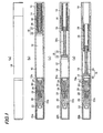
FIG. 1] FIG. 1 is an illustrative diagram showing states of a liquid substance advancing container with a cap provided according to the first embodiment of the present invention, (a) a side view, (b) vertical section at the start of advancing, (c) vertical section during advancing and (d) vertical section at the end of advancing. - [
FIG. 2] FIG. 2 is an illustrative diagram showing states of the liquid substance advancing container with the cap removed according to the first embodiment of the present invention, (a) a side view, (b) vertical section at the start of advancing, (c) vertical section during advancing and (d) vertical section at the end of advancing. - [
FIG. 3] FIG. 3 is an illustrative diagram of a bar member of a piston in the liquid substance advancing container according to the first embodiment, (a) a perspective view from the front, (b) a view from the front, (c) a side view, (d) a vertical section, (e) a side view from another angle, (f) a vertical section of (e), (g) a perspective view from the rear, and (h) a view from the rear. - [
FIG. 4] FIG. 4 is an illustrative diagram of a sealing part of the piston in the liquid substance advancing container according to the first embodiment, (a) a perspective view from the front, (b) a view from the front, (c) a side view, (d) a vertical section, (e) a side view from another angle, (f) a vertical section of (e), (g) a perspective view from the rear, and (h) a view from the rear. - [
FIG. 5] FIG. 5 is an illustrative diagram of a rotational body of the liquid substance advancing container according to the first embodiment, (a) a perspective view from the front, (b) a view from the front, (c) a side view, (d) a side view from another angle, (e) a vertical section of (d), (f) a perspective view from the rear, and (g) a view from the rear. - [
FIG. 6] FIG. 6 is an illustrative diagram of a front bar-like part (thick thread) that is located between the bar member of the piston and the rotational body to be screwed with the thread of each in the liquid substance advancing container according to the first embodiment, (a) a perspective view from the front, (b) a view from the front, (c) a side view, (d) a vertical section, (e) a side view from another angle, (f) a vertical section of (e), (g) a perspective view from the rear, and (h) a view from the rear. - [
FIG. 7] FIG. 7 is an illustrative diagram showing states of a liquid substance advancing container with a cap provided according to a second embodiment of the present invention, (a) a side view, (b) vertical section at the start of advancing, (c) vertical section during advancing and (d) vertical section at the end of advancing. - [
FIG. 8] FIG. 8 is an illustrative diagram showing states of the liquid substance advancing container with the cap removed according to the second embodiment of the present invention, (a) a side view, (b) vertical section at the start of advancing, (c) vertical section during advancing and (d) vertical section at the end of advancing. - [
FIG. 9] FIG. 9 is an illustrative diagram of a piston integrated with a sealing part and a bar-like part in the liquid substance advancing container according to the second embodiment, (a) a perspective view from the front, (b) a view from the front, (c) a side view, (d) a side view from another angle, (e) a vertical section of (d), (f) a perspective view from the rear, and (g) a view from the rear. - [
FIG. 10] FIG. 10 is an illustrative diagram showing states of a liquid substance advancing container with a cap provided according to a third embodiment of the present invention, (a) a side view, (b) vertical section at the start of advancing, (c) vertical section during advancing and (d) vertical section at the end of advancing. - [
FIG. 11] FIG. 11 is an illustrative diagram showing states of the liquid substance advancing container with the cap removed according to the third embodiment of the present invention, (a) a side view, (b) vertical section at the start of advancing, (c) vertical section during advancing and (d) vertical section at the end of advancing. - [
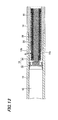
FIG. 12] FIG. 12 is an illustrative diagram of a rotational body with slits formed in the liquid substance advancing container according to the third embodiment, (a) a perspective view from the front, (b) a view from the front, (c) a side view, (d) a vertical section, (e) a side view from an angle different from (c), (f) a vertical section of (e), (g) a perspective view from the rear, and (h) a view from the rear. - [
FIG. 13] FIG. 13 is an illustrative diagram of the liquid substance advancing mechanism of the rotational body and front bar-like part and the like provided at the rear part of the barrel body for moving the piston forward in the liquid substance advancing container according to the third embodiment. - [
FIG. 14] FIG. 14 is an illustrative diagram showing states of a liquid substance advancing container with a cap provided according to a fourth embodiment of the present invention, (a) vertical section at the start of advancing, (b) vertical section at the initial stage of advancing, (c) vertical section during advancing and (d) vertical section at the end of advancing. - Next, the embodiments of the present invention will be described with reference to the accompanying drawings.
-
FIGS. 1 to 6 are illustrative diagrams of a liquid substance advancing container according to the first embodiment of the present invention. -
FIGS. 1 and2 show the illustrate diagrams of a liquid substance advancing container according to the first embodiment,FIG. 1 a state with the cap put on andFIG. 2 a state with the cap removed. - As shown in
FIGS. 1 and2 , the liquid substance advancing container stores a liquid substance in areservoir 12 formed in abarrel body 10 and advances apiston 18 inside thereservoir 12 by rotating, relatively to abarrel body 10, ahandle 16 of arotational body 14 exposed from a rear end of thebarrel body 10 to deliver the liquid substance toward an applyingpart 20 at a front end of thebarrel body 10. - The front end of the
barrel body 10 is detachably attached with acap 22. When the liquid substance advancing container is not used, the front end is covered with thecap 22 as shown inFIG. 1 so that the liquid substance in the applyingpart 20 is prevent from drying, whereas when in use thecap 22 is removed so that applyingpart 20 is advanced. - As shown in
FIG. 1 , in the liquid substance advancing container, aseal ball receiver 24, apipe joint 26, apipe 28, afront barrel 30 and the applyingpart 20 are attached to thefront end 10a of thebarrel body 10, so that the liquid substance advanced from thereservoir 12 is delivered through thepipe 28 to the front end of the applyingpart 20. - The
front end 10a of thebarrel body 10 is stepped to be smaller in diameter than the middle part. The cylindricalseal ball receiver 24 is fitted and inserted into thefront end 10a. An unillustrated seal ball is fitted in the rear of thisseal ball receiver 24 while thepipe joint 26 is attached at the front part of the seal ball receiver. Thepipe 28 is attached in front of thepipe joint 26. Thispipe 28 is fitted into the applyingpart 20 of a brush from a rear end of the applyingpart 20. - The
pipe joint 26 and the hollow conduit of thepipe 28 are made to communicate with the applyingpart 20. When the seal ball has fitted in theseal ball receiver 24, communication of the hollow conduit with thereservoir 12 is closed by the seal ball. Theseal ball receiver 24 has an unillustrated engagement structure for the seal ball. When the engagement structure is released at the start of use, the seal ball is made to fall into thereservoir 12 so that the liquid substance is supplied through thepipe joint 26 and thepipe 28 to the applyingpart 20. - The
front barrel 30 tapered or reduced in diameter toward the front, covers the rear part of the applyingpart 20, thepipe 28, thepipe joint 26 and theseal ball receiver 24 and is fitted to thefront end 10a of thebarrel body 10. An interlocking arrangement is formed on the inner peripheral surface of thefront barrel 30 and the outer peripheral surface of thefront end 10a of thebarrel body 10 so as to tightly fix one to another (seeFIGS. 1 and2 ). - Further, the front barrel is formed so as to have the
cap 22 containing aninner cap 22a andinner cap spring 22b fitted after use of the applicator, as shown inFIG. 1 . When thecap 22 is used, thecap 22 covers thefront barrel 30 while theinner cap 22a encloses thefront barrel 30 and the applyingpart 20 by virtue of the urging force of theinner cap spring 22b so as to keep the applyingpart 20 air-tight and prevent the applyingpart 20 from drying. - Moreover, when the applicator is unused, the seal ball is fitted in
seal ball receiver 24, and the seal ball is plunged into thereservoir 12 at the start of use so as to establish communication between thereservoir 12 and thepipe 28. An agitating ball may be put inside thereservoir 12 so as to agitate the content liquid substance by shaking the liquid substance advancing container up and down. - The
piston 18 is formed of a sealingpart 32 at the front (outer peripheral) and abar member 34 in the rear part. Sealingpart 32 comes in sliding contact with the inner wall of thereservoir 12 of thebarrel body 10. Thebar member 34 has a threaded section on the inner periphery or outer periphery and is arranged to be movable in the axial direction and restrained from moving in the rotational direction. - A front bar-
like part 36 extended forward from thehandle 16 is formed with a threaded section that directly screw-fitted to the threaded section of thebar member 34 in the rear part of thepiston 18. - In the first embodiment, the front bar-
like part 36 of therotational body 14 is a thick cylindrical body that is screw-fitted to the interior side of the front part of thehandle 16 and extended forward. This front bar-like part 36 is formed with a threaded section 38 (female threadedsection 38b) into which the threadedsection 34a of thebar member 34 in the rear part of thepiston 18 is screw-fitted. - Specifically, the front bar-
like part 36 screw-fitted to therotational body 14 is formed with threaded sections 38 (male thread 38a andfemale thread 38b) on both the inner and outer peripheral surfaces, as shown inFIG. 6 . That is, the threadedsection 38a of the male thread on the outer peripheral surface is formed so as to be screw-fitted to the threadedsection 14b of the female thread while thefemale thread 38b into which thetreaded portion 34a is screw-fitted is formed on the inner surface. The threadedsection 38a of the male thread on the outer periphery of the front bar-like part 36 is continuously extended from the front end of the front bar-like part 36 to the vicinity of the rear end. The rear end of the front bar-like part 36 forms ablank section 38c without any thread. - The threaded
section 14b of therotational body 14 may be formed with slits that separate the thread (a configuration of the threadedsection 14b formed withslits 14c will be described in the following third embodiment (seeFIG. 12 )). - Accordingly, the threaded
section 14b of the rotational body 14 (handle 16) is indirectly screw-fitted to the threadedsection 34a ofbar member 34 via the threadedsection 38 of the front bar-like part 36, as shown inFIG. 2 . - The sliding friction of screw fitting between the threaded
section 34a of thebar member 34 fixed to thepiston 18 and the inner threadedsection 38b of the front bar-like part 36 is set so as to be smaller than the sliding friction of screw fitting between the outer threadedsection 38a of the front bar-like part 36 and the threadedsection 14b of therotational body 14. - As the
handle 16 is rotated relative to thebarrel body 10 from a state shown inFIG. 2(b) , thebar member 34 of thepiston 18 moves forward thanks to the aforementioned difference in sliding friction, hence the sealingpart 32 advances. Since thebar member 34 is locked by the front bar-like part 36 after the forward movement of thepiston 18 at the stage shown inFIG. 2(c) , a further rotation of thehandle 16 causes the front bar-like part 36 to advance relative to therotational body 14 and further move the sealingpart 32 forward. Thus, this mechanism provides a multi-stage extending and retracting configuration as shown inFIGS. 2 (b) to 2 (d) . Though therotational body 14 is formed to be hollow inside with its tail end open herein, a closing plug may be fitted so as to hide the interior for improvement in design. - Herein, the
above piston 18 has a structure in which the sealingpart 32 and thebar member 34 are joined. - As shown in
FIG. 3 , thebar member 34 has the threadedsection 34a formed on the outer peripheral surface in the approximately middle part thereof other than the front and rear ends. Formed in the front end of thebar member 34 is a variant-shapedengaging part 34b to be mate with the sealingpart 32 while ablank section 34c without any thread is formed in the rear end. Theengaging part 34b is thin with respect to the axial direction, forming a roughly shield-like shape. - The sealing
part 32 is formed in a shape of rotational body like an approximate chalice or wheel as shown inFIG. 4 . The outer peripheral surface is formed so that the front and rear ends are greater in diameter than the middle part while two strips formed along with a circumferential direction are formed on the outer peripheral surface as sealing surfaces that slide in contact with the interior wall of thereservoir 12 of thebarrel body 10. The sealingpart 32 has an engagedpart 32a projected cylindrically rearward from the hub-like portion in the interior portion thereof. - This engaged
part 32a forms an engagement structure such as a latch or the like in which a slit is formed on the side surface of the projected cylindrical part. Theengaging part 34b (shown inFIG. 3 ) of thebar member 34 is inserted from the slit and fixed therein, whereby the sealingpart 32 andbar member 34 are fixed with respect to the rotational direction and the front-to-rear direction, forming theintegrated piston 18 that moves forward and backward. - As shown in
FIG. 5 , therotational body 14 is an approximate hollow cylinder and the outer peripheral of the rotational body has the rear part greater in diameter than the front part. Therotational body 14 forms thehandle 16 the user can hold and rotate. Further, an annular rib is formed on the outer peripheral surface of the front part as afitting part 14a so that the rotational body is rotatable relative to but will not slip off from thebarrel body 10. The female threadedsection 14b is formed in the front part on the inner peripheral surface of therotational body 14. - Further, the
bar member 34 in the rear part of thepiston 18 can move together in the front-and-rear direction with the sealingpart 32 relative to the inner wall of thereservoir 12 and is restricted in the rotational direction. - The outer peripheral surface of the sealing
part 32 in the front part of thepiston 18 can slider in contact with the inner wall of thereservoir 12 of thebarrel body 10 and move in the axial direction of thebarrel body 10 while the restriction of thepiston 18 in the rotational direction is assured by the contact friction so that the piston will not rotate easily. That is, the sealingpart 32 in the front part of thepiston 18 is adapted to come into sliding contact with the inner wall of thereservoir 12 of thebarrel body 10 by providing a suitable amount of interference to prevent the liquid content from leaking. The frictional force generated by the interference retains the piston so as not to rotate easily in the circumferential direction. - The
piston 18 and other parts are molded of resin. The amount of interference is adjusted by setting the dimensions of the moldings. Other than this, it is possible to prevent easy rotation by selecting the material. - The advancing operation of the liquid substance advancing container according to the first embodiment will be described.
- The threaded
section 34a of thebar member 34 fixed to thepiston 18 is screw-fittedwith the inner threadedsection 38b of the front bar-like part 36 while the outer threadedsection 38a of the front bar-like part 36 is screw-fitted with the threadedsection 14b of the rotational body. - When unused, the
piston 18 in the advancing container is located at the backward limit so as to maximize the volume of thereservoir 12. - When used, the
handle 16 is held to turn therotational body 14 relative to thebarrel body 10. As the user operates to rotate thehandle 16 relative to thebarrel body 10, thebar member 34 of thepiston 18 advances due to the aforementioned difference in sliding friction, hence the sealingpart 32 andpiston 18 move forward. When the bar member has advanced to some degree, theblank section 34c without threadedsection 34a abuts the inner threadedsection 38b of the front bar-like part 36, so that the bar member is fixed to the front bar-like part 36 and set in a locked state without any further advance.FIG. 2(c) shows the limit of advance. - A further rotation of the
handle 16 causes the front bar-like part 36 located outside to go ahead relative to therotational body 14 as shown inFIG. 2(d) and hence further advances the sealingpart 32 because the outer male threadedsection 38a is screw-fitted with thefemale thread 14b of therotational body 14. Herein, when theblank section 38c of the threadedsection 38 abuts thefemale thread 14b of therotational body 14, thepiston 18 will go no further, so that it is possible to prevent the piston from overgoing. - Because of the advancing process described above, the liquid substance advancing container is configured so that the
bar member 34 of thepiston 18 and the front bar-like part 36 can extend and retract relative to therotational body 14 in multiple stages. - The present invention should not be limited to the configuration of the liquid substance advancing container according to the first embodiment, but can be modified in various ways.
- A liquid substance advancing container according to the second embodiment of the present invention will be described with reference to
FIGS. 7 ,8 and9 . The same components with those in the first embodiment are allotted with the same reference numerals. - In this liquid substance advancing container, as shown in
FIGS. 7 to 9 thepiston 18 is molded of resin integrally with the sealingpart 32 in the front and thebar member 34 in the rear. Since thebar member 34 having a threaded section on the outer periphery is integrated, the bar member is arranged to be movable in the axial direction and restricted in the rotational direction in the same manner as thepiston 18. Similarly to the first embodiment, theblank section 34c is not threaded, in order to assemble the piston into the front bar-like part 36, thefemale thread 38b may be formed with slits for separation, theblank section 34c may be formed with slits, or the two may be formed with slits. - The applying
part 20 has a roughly conical shape with a plurality of concentric disks (flanges) radially projected and arranged concentrically from the front end to the rear end at regular intervals. This applyingpart 20 is used to apply a liquid such as mascara or the like, and the projected part of disks forms a structure that enables easy application to cover the eyelashes with the liquid. The periphery of the applyingpart 20 is converted by the front barrel and inserted into thefront end 10a of thebarrel body 10. - Since in this liquid substance advancing container according to the second embodiment the
piston 18 has a simple integrated configuration, it is possible to reduce the number of assembly steps compared to the first embodiment. - A liquid substance advancing container according to the third embodiment of the present invention will be described with reference to
FIGS. 10 to 13 . The same components with those in the first embodiment are allotted with the same reference numerals. -
FIG. 10 shows unused states with the cap attached,FIG. 11 shows use states with the cap removed,FIG. 12 is an illustrative diagram of a rotational body, andFIG. 13 is an illustrative vertical sectional diagram of the rear part of the liquid substance advancing container. - In this liquid substance advancing container, the
piston 18 has the same configuration where the sealingpart 32 and thebar member 34 are joined in as in the first embodiment. - The
cap 22 is fitted in the unused state as shown inFIG. 10 , whereas thecap 22 is removed in the use state as shown inFIG. 11 .FIGS. 10 (a) and11 (a) show the state before thepiston 18 is advanced.FIGS. 10(b) and11(b) show the state during thepiston 18 is being advanced.FIGS. 10(c) and11(c) show the state where thepiston 18 has been advanced to the limit. - Herein, the
rotational body 14 is an approximate hollow cylinder with the outer peripheral of the rear part greater in diameter than the front part, forming ahandle 16 the user can hold and rotate, as shown inFIGS. 12 and13 . Further, an annular rib is formed on the outer peripheral surface of the front part as afitting part 14a so that the rotational body is rotatable relative to but will not slip off from thebarrel body 10. A female threadedsection 14b is formed in the front part on the inner peripheral surface of therotational body 14. - Slits that separate the threaded section are formed at one end of the front bar-like part of the
rotational body 14. In the third embodiment, slits 14c are formed in the front of thehandle 16 as a part of therotational body 14 to separate the threadedsection 14b that mates with the front bar-like part 36. - Specifically, two
slits 14c located diametrically opposite positions are formed in the front part of therotational body 14 so as to cut the threadedsection 14b in the longitudinal direction from the front end to the rear. - Formation of these
slits 14c allows the front part of therotational body 14 to slightly open in diameter so that the front bar-like part 36 can be gently screwed in when the front bar-like part 36 is assembled. Alternatively, enlargement in diameter from theslits 14c makes it possible to press fit the front bar-like part 36 directly into the rotational body. - In the advancing mechanism, the
slit 14c may be arranged in close proximity to the inner peripheral surface (designated by 10b) of thebarrel body 10, as shown inFIG. 13 . In the third embodiment, the clearance 8 between theslit 14c and the innerperipheral surface 10b is specified to be 0.5 mm or smaller. This clearance can be specified as appropriate. - A liquid substance advancing container according to the fourth embodiment of the present invention will be described with reference to
FIG. 14 . The same components as those in the first embodiment will be allotted with the same reference numerals. - As shown in
FIG. 14 , this liquid substance advancing container includes arear sleeve 40 that is screw-fitted on the outer periphery of the front bar-like part 36 and screw-fitted into the inner periphery of the threadedsection 14b of therotational body 14. - An elastic part (spring) 42 is disposed between the front bar-
like part 36 and therotational body 14. Since this liquid substance advancing container is configured so that theelastic part 42 urges the front bar-like part 36 forward, thepiston 18 can be moved forward not only by the advancing force resulting from the rotation of therotational body 14 but also by the advancing force resulting from the pressing force of theelastic part 42 applied via the front bar-like part 36, as shown inFIGS. 14(a) to 14(b) . - Specifically, in the fourth embodiment, in order to receive the rear end of the
elastic part 42, a roughly cup-like sprint socket 44 that is open on the front side and closed on the rear side is provided inside the roughly cylindricalrotational body 14 to close the rear opening of therotational body 14. - The
rear sleeve 40 is arranged coaxially between therotational body 14 and the front bar-like part 36. Thisrear sleeve 40 is formed with threads (female and male threads) on both the inner and outer peripheral surfaces. In therear sleeve 40, a male thread is formed on the outer peripheral surface from the front to rear while the inner peripheral surface is reduced in diameter and formed with a female thread in the front part and stepped at the end of the female thread and enlarged in diameter with a flat interior surface without any threads. - The threaded
section 14b on the inner periphery of therotational body 14 is screw-fitted on the male thread of the outer peripheral surface of therear sleeve 40 while the outermale thread 38a of the front bar-like part 36 is screw-fitted into the female thread on the inner peripheral surface of therear sleeve 40. In this case, thepiston 18 is formed by joining afront sealing part 32 to the front end of arear bar member 34 by screw-fitting a screw penetrated through from the front. Here, thepiston 18 may be formed by uniting the sealingpart 32 and thebar member 34 as in the first embodiment shown inFIG. 1 and as in the third embodiment shown inFIG. 10 . Alternatively, the piston may be integrally formed of the sealingpart 32 and thebar member 34 as in the second embodiment shown inFIG. 8 . - The rear part of the
rear sleeve 40 is formed so as to be able to receive the elastic part (spring) 42 held in thespring socket 44 so as to press therear sleeve 40 forward. - As shown in
FIGS. 14 (a) to 14(b) , as the user starts rotating therotational body 14, not only the advancing force of therear sleeve 40 resulting from the rotational force but also the pressing force of theelastic part 42 acts on therear sleeve 40 as the advancing force. - Accordingly, the rotational force of the
rotational body 14 together with the elastic force of theelastic part 42 acts on therear sleeve 40 as the advancing force so as to apply advancing force to thepiston 18 via the front bar-like part 36 and move thepiston 18 forward. When the flange-formed part on the outer periphery at the rear end of therear sleeve 40 abuts the stepped portion in the inner periphery of therotational body 14 so that therear sleeve 40 reaches the forward limit, the rotational body becomes locked so as to turn therear sleeve 40 as therotational body 40 rotates. - Then, with the advancing operation of the
rotational body 14, therear sleeve 40 advances the front bar-like part 36 as shown in the same figure (c). When the front bar-like part 36 reaches the forward limit, the front bar-like part 36 starts rotating to advance thepiston 18 via thebar member 34 as shown in the same figure (d). - Accordingly, in the liquid substance advancing container of the fourth embodiment, in the operation of advancing the
piston 18, the pressing force from theelastic part 42 can be used together with the rotational force of therotational body 14 to apply advancing torque to thepiston 18. Particularly, because advance of thepiston 18 by therotational body 14 having a large outside diametric thread can be assisted, it is possible to deliver the application liquid with light rotational force. When the outside diameter of the thread of therotational body 14 is made large without providing therear sleeve 40 and theelastic part 42, the inside diameter of the threadedsection 14b of therotational body 14 and the outside diameter of the screw-fitted thread of the front bar-like part 36 become large, which requires large rotational force (torque) to turn therotational body 14 for advancing action because sliding resistance between the screw-fitting threads becomes large. In contrast, in the fourth embodiment, since the advance of the piston is assisted by the urging force of theelastic part 42, it is possible to turn therotational body 14 lightly. - Further, making the thread pitch greater enable quick advance of the content by a lower number of rotation when the user begins to use. Though the advancing operation requires a greater rotational force (torque) when the thread pitch is made greater, the liquid can be quickly delivered with light force because of assistance of the
elastic part 42. - In the first to fourth embodiments having been described in the present invention, the
bar member 34, front bar-like part 36 androtational body 14 are used to advance the two-stage piston 18. However, it is possible to use multiple front bar-like parts to advance the piston by three or more stages. - Further, the male and female threads in the threaded sections of the bar member, front bar-like part and rotational body may be configured in other ways. For example, it is possible to provide a configuration in which the bar member is hollowed so as to have the front bar-like part screwed in while a male threaded rod from the rotational body is screwed into the front bar-like part.
- Other than those for storing the fluid (liquid) cosmetics and chemicals, the liquid substance advancing container of the present invention may be used as one that stores a liquid substance such as mouthwash, medicine and the like in the reservoir and sends out the stored liquid substance to an applying part by turning the tail end for delivery operation.
-
- 10
- barrel body
- 10a
- front end
- 12
- reservoir
- 14
- rotational body
- 14a
- fitting part
- 14b
- threaded section
- 16
- handle
- 18
- piston
- 18b
- engaged part
- 20
- applying part
- 22
- cap
- 30
- front barrel
- 32
- sealing part
- 32a
- engaged part
- 34
- bar member
- 34a
- threaded section
- 34b
- engaging part
- 34c
- blank section
- 36
- front bar-like part
- 38
- threaded section
- 38a
- outer male thread
- 38b
- inner female thread
- 40
- rear sleeve
- 42
- elastic part
Claims (7)
- A liquid substance advancing container that stores a liquid content in a reservoir provided in a barrel body, moves a piston in the reservoir forward by turning a handle of a rotational body exposed from a rear end of the barrel body, relative to the barrel body, to advance the content to a front end of the barrel body,
wherein
the piston is formed of a sealing part in a front part of the piston that comes in sliding contact with an inner wall of the reservoir of the barrel body and a bar member in a rear part of the piston that has a threaded section on an inner periphery or an outer periphery, is movable in an axial direction and is restrained from moving with respect to a rotational direction,
a front bar-like part extended forward from the handle is formed with a threaded section that is directly or indirectly screw-fitted to the threaded section of the bar member in the rear part of the piston, and,
as the handle is rotated relative to the barrel body, the piston advances and then after full advance of the piston the front bar-like part can extend and retract by multiple stages. - The liquid substance advancing container according to Claim 1, wherein
the bar member in the rear part of the piston together with the sealing part is movable in a front to rear direction and restrained from moving in an rotational direction, relative to the inner wall of the reservoir, and,
the piston makes an outer peripheral surface of the sealing part in the front part of the piston come into sliding contact with the inner wall of the reservoir of the barrel body, is movable in the axial direction and is retained by a frictional force so as not to easily rotate in the rotational direction. - The liquid substance advancing container according to Claim 2, wherein
the piston makes the sealing part in the front part of the piston come into sliding contact with the inner wall of the reservoir of the barrel body with an appropriate amount of interference in order to prevent leakage of the liquid content, and is retained by the frictional force generated by the interference so as not to easily rotate in a circumferential direction. - The liquid substance advancing container according to any one of Claims 1 to 3, wherein a threaded section is formed on an outer periphery or an inner periphery of the bar member in the rear part of the piston, the front bar-like part extended forward from the handle of the rotational body is formed with the threaded section that is directly or indirectly screw-fitted to the threaded section of the bar member in the rear part of the piston, and a blank section with no thread is provided in any one end of the bar member and the front bar-like part in which threaded sections thereof are screw-fitted to each other.
- The liquid substance advancing container according to any one of Claims 1 to 4, wherein the threaded section is formed on the outer periphery or the inner periphery of the bar member in the rear part of the piston, the front bar-like part extended forward from the handle of the rotational body is formed with the threaded section that is directly or indirectly screw-fitted to the threaded section of the bar member in the rear part of the piston, and,
a slit that separates the threaded section is formed in one end of the front bar-like part of the rotational body. - The liquid substance advancing container according to Claim 5, wherein the slit is formed in close proximity to the inner peripheral surface of the barrel body.
- The liquid substance advancing container according to any one of Claims 1 to 6, wherein an elastic part is provided between the rotational body and the front bar-like part.
Applications Claiming Priority (3)
| Application Number | Priority Date | Filing Date | Title |
|---|---|---|---|
| JP2013034730 | 2013-02-25 | ||
| JP2014029446A JP6424005B2 (en) | 2013-02-25 | 2014-02-19 | Liquid feed container |
| PCT/JP2014/054430 WO2014129645A1 (en) | 2013-02-25 | 2014-02-25 | Liquid substance advancing container |
Publications (3)
| Publication Number | Publication Date |
|---|---|
| EP2959794A1 true EP2959794A1 (en) | 2015-12-30 |
| EP2959794A4 EP2959794A4 (en) | 2016-10-12 |
| EP2959794B1 EP2959794B1 (en) | 2020-12-09 |
Family
ID=51391421
Family Applications (1)
| Application Number | Title | Priority Date | Filing Date |
|---|---|---|---|
| EP14753988.6A Not-in-force EP2959794B1 (en) | 2013-02-25 | 2014-02-25 | Liquid substance advancing container |
Country Status (4)
| Country | Link |
|---|---|
| US (1) | US9924777B2 (en) |
| EP (1) | EP2959794B1 (en) |
| JP (1) | JP6424005B2 (en) |
| WO (1) | WO2014129645A1 (en) |
Cited By (1)
| Publication number | Priority date | Publication date | Assignee | Title |
|---|---|---|---|---|
| EP3466297A4 (en) * | 2016-05-31 | 2019-06-12 | Shya Hsin Packaging Industry (China) Co., Ltd. | COSMETIC PEN WITH HIGH CAPACITY |
Families Citing this family (1)
| Publication number | Priority date | Publication date | Assignee | Title |
|---|---|---|---|---|
| KR101597115B1 (en) * | 2014-10-08 | 2016-03-07 | (주)연우 | Cosmetic Dispencer |
Family Cites Families (19)
| Publication number | Priority date | Publication date | Assignee | Title |
|---|---|---|---|---|
| JPS633311A (en) | 1986-06-23 | 1988-01-08 | Toshiba Corp | Three-dimensional position detector |
| JPH0418497Y2 (en) * | 1986-06-23 | 1992-04-24 | ||
| US5100252A (en) * | 1990-07-02 | 1992-03-31 | Grigory Podolsky | Toothbrush |
| JP2736039B2 (en) * | 1994-08-25 | 1998-04-02 | 株式会社トキワ | Cosmetic dispensing container |
| FR2825904B1 (en) * | 2001-06-15 | 2004-07-09 | Oreal | STICK, ESPECIALLY FOR A PRODUCT IN THE FORM OF A CREAM, GEL, OR PASTE |
| JP2004160117A (en) * | 2002-11-11 | 2004-06-10 | Masayuki Kuzuu | Storage case for lipstick or the like for using up lipstick or the like |
| EP1681979A1 (en) * | 2003-11-13 | 2006-07-26 | Unilever Plc | Fabric cleaning fluid and dispensing device |
| JP4739847B2 (en) * | 2005-07-28 | 2011-08-03 | 株式会社トキワ | Filler extrusion container |
| EP1769698A1 (en) * | 2005-09-30 | 2007-04-04 | OEKAMETALL OEHLHORN GmbH & Co. KG | Cosmetic application container, especial lip pomade, preferably in stick form |
| JP4847791B2 (en) * | 2005-10-12 | 2011-12-28 | 株式会社トキワ | Filler extrusion container |
| JP4607746B2 (en) * | 2005-11-28 | 2011-01-05 | 株式会社トキワ | Contents extrusion container |
| JP4139838B2 (en) * | 2006-08-18 | 2008-08-27 | 株式会社トキワ | Filler extrusion container |
| US8172472B2 (en) * | 2007-11-08 | 2012-05-08 | Tokiwa Corporation | Stick-shaped material extruding container |
| US8104984B2 (en) * | 2007-12-14 | 2012-01-31 | Tokiwa Corporation | Filled material extruding container |
| JP2009247427A (en) * | 2008-04-02 | 2009-10-29 | Mitsubishi Pencil Co Ltd | Rotary type dispensing container |
| JP5545681B2 (en) * | 2009-03-03 | 2014-07-09 | 三菱鉛筆株式会社 | Liquid feed container |
| JP5545632B2 (en) | 2009-03-03 | 2014-07-09 | 三菱鉛筆株式会社 | Liquid feed container |
| JP5467952B2 (en) * | 2010-07-07 | 2014-04-09 | 三菱鉛筆株式会社 | Applicator |
| KR101259431B1 (en) * | 2011-07-26 | 2013-04-30 | (주)연우 | Pencil type cosmetic case |
-
2014
- 2014-02-19 JP JP2014029446A patent/JP6424005B2/en not_active Expired - Fee Related
- 2014-02-25 EP EP14753988.6A patent/EP2959794B1/en not_active Not-in-force
- 2014-02-25 US US14/769,659 patent/US9924777B2/en not_active Expired - Fee Related
- 2014-02-25 WO PCT/JP2014/054430 patent/WO2014129645A1/en not_active Ceased
Cited By (1)
| Publication number | Priority date | Publication date | Assignee | Title |
|---|---|---|---|---|
| EP3466297A4 (en) * | 2016-05-31 | 2019-06-12 | Shya Hsin Packaging Industry (China) Co., Ltd. | COSMETIC PEN WITH HIGH CAPACITY |
Also Published As
| Publication number | Publication date |
|---|---|
| JP6424005B2 (en) | 2018-11-14 |
| EP2959794B1 (en) | 2020-12-09 |
| US20160007715A1 (en) | 2016-01-14 |
| EP2959794A4 (en) | 2016-10-12 |
| WO2014129645A1 (en) | 2014-08-28 |
| US9924777B2 (en) | 2018-03-27 |
| JP2014184135A (en) | 2014-10-02 |
Similar Documents
| Publication | Publication Date | Title |
|---|---|---|
| KR102596688B1 (en) | knock type writing instrument | |
| US9738113B2 (en) | Multi pencil | |
| US9486054B2 (en) | Applying material extruding container | |
| CN107048673A (en) | press pen | |
| JP2017035235A5 (en) | ||
| JP6600489B2 (en) | Rotating feeding container | |
| JP6045127B2 (en) | Applicator | |
| JP7394199B2 (en) | cosmetic applicator | |
| CN105266344B (en) | Rod-shaped object unscrewing container | |
| JP5393599B2 (en) | Coating material extrusion container | |
| EP2959794B1 (en) | Liquid substance advancing container | |
| JP7348658B2 (en) | Cosmetic dispensing container | |
| KR20130056229A (en) | Knock-type applicator | |
| WO2014192175A1 (en) | Cartridge-type cosmetic container | |
| JP2016220917A (en) | Rotation delivery container | |
| US9301590B2 (en) | Retractable cosmetic pencil | |
| US11896112B2 (en) | Feeding container | |
| JP2012070780A (en) | Cosmetic stick-dispensing container | |
| JP5498303B2 (en) | Stick-shaped cosmetics feeding container | |
| JP4838393B1 (en) | Stick-shaped cosmetic material feeding container | |
| JPH0232881B2 (en) | ||
| JP6262466B2 (en) | Solid bar cosmetic container | |
| JP6318344B2 (en) | Cartridge-type contents extrusion container | |
| US11857058B2 (en) | Cosmetic container with scraping member | |
| JP7060861B2 (en) | Coating material extrusion container |
Legal Events
| Date | Code | Title | Description |
|---|---|---|---|
| PUAI | Public reference made under article 153(3) epc to a published international application that has entered the european phase |
Free format text: ORIGINAL CODE: 0009012 |
|
| 17P | Request for examination filed |
Effective date: 20150925 |
|
| AK | Designated contracting states |
Kind code of ref document: A1 Designated state(s): AL AT BE BG CH CY CZ DE DK EE ES FI FR GB GR HR HU IE IS IT LI LT LU LV MC MK MT NL NO PL PT RO RS SE SI SK SM TR |
|
| AX | Request for extension of the european patent |
Extension state: BA ME |
|
| DAX | Request for extension of the european patent (deleted) | ||
| A4 | Supplementary search report drawn up and despatched |
Effective date: 20160909 |
|
| RIC1 | Information provided on ipc code assigned before grant |
Ipc: A45D 34/04 20060101AFI20160905BHEP |
|
| RIN1 | Information on inventor provided before grant (corrected) |
Inventor name: NAKAJIMA, NOBUYUKI Inventor name: TAMANO, HISAMI Inventor name: KYOGOKU, YUUSUKE Inventor name: SHINMURA, YUKAKO Inventor name: SATOU, HIROSHI Inventor name: ENDOU, MITSURU Inventor name: AKAISHI, TETSUAKI Inventor name: NAKASHIMA, ATSUSHI |
|
| STAA | Information on the status of an ep patent application or granted ep patent |
Free format text: STATUS: EXAMINATION IS IN PROGRESS |
|
| 17Q | First examination report despatched |
Effective date: 20180820 |
|
| GRAP | Despatch of communication of intention to grant a patent |
Free format text: ORIGINAL CODE: EPIDOSNIGR1 |
|
| STAA | Information on the status of an ep patent application or granted ep patent |
Free format text: STATUS: GRANT OF PATENT IS INTENDED |
|
| INTG | Intention to grant announced |
Effective date: 20200623 |
|
| RAP1 | Party data changed (applicant data changed or rights of an application transferred) |
Owner name: MITSUBISHI PENCIL COMPANY, LIMITED |
|
| RIN1 | Information on inventor provided before grant (corrected) |
Inventor name: SATOU, HIROSHI Inventor name: ENDOU, MITSURU Inventor name: NAKAJIMA, NOBUYUKI Inventor name: KYOGOKU, YUUSUKE Inventor name: SHINMURA, YUKAKO Inventor name: AKAISHI, TETSUAKI Inventor name: TAMANO, HISAMI Inventor name: NAKASHIMA, ATSUSHI |
|
| GRAS | Grant fee paid |
Free format text: ORIGINAL CODE: EPIDOSNIGR3 |
|
| GRAA | (expected) grant |
Free format text: ORIGINAL CODE: 0009210 |
|
| STAA | Information on the status of an ep patent application or granted ep patent |
Free format text: STATUS: THE PATENT HAS BEEN GRANTED |
|
| AK | Designated contracting states |
Kind code of ref document: B1 Designated state(s): AL AT BE BG CH CY CZ DE DK EE ES FI FR GB GR HR HU IE IS IT LI LT LU LV MC MK MT NL NO PL PT RO RS SE SI SK SM TR |
|
| REG | Reference to a national code |
Ref country code: GB Ref legal event code: FG4D |
|
| REG | Reference to a national code |
Ref country code: AT Ref legal event code: REF Ref document number: 1342475 Country of ref document: AT Kind code of ref document: T Effective date: 20201215 Ref country code: CH Ref legal event code: EP |
|
| REG | Reference to a national code |
Ref country code: DE Ref legal event code: R096 Ref document number: 602014073178 Country of ref document: DE |
|
| REG | Reference to a national code |
Ref country code: IE Ref legal event code: FG4D |
|
| PG25 | Lapsed in a contracting state [announced via postgrant information from national office to epo] |
Ref country code: FI Free format text: LAPSE BECAUSE OF FAILURE TO SUBMIT A TRANSLATION OF THE DESCRIPTION OR TO PAY THE FEE WITHIN THE PRESCRIBED TIME-LIMIT Effective date: 20201209 Ref country code: RS Free format text: LAPSE BECAUSE OF FAILURE TO SUBMIT A TRANSLATION OF THE DESCRIPTION OR TO PAY THE FEE WITHIN THE PRESCRIBED TIME-LIMIT Effective date: 20201209 Ref country code: NO Free format text: LAPSE BECAUSE OF FAILURE TO SUBMIT A TRANSLATION OF THE DESCRIPTION OR TO PAY THE FEE WITHIN THE PRESCRIBED TIME-LIMIT Effective date: 20210309 Ref country code: GR Free format text: LAPSE BECAUSE OF FAILURE TO SUBMIT A TRANSLATION OF THE DESCRIPTION OR TO PAY THE FEE WITHIN THE PRESCRIBED TIME-LIMIT Effective date: 20210310 |
|
| REG | Reference to a national code |
Ref country code: AT Ref legal event code: MK05 Ref document number: 1342475 Country of ref document: AT Kind code of ref document: T Effective date: 20201209 |
|
| PG25 | Lapsed in a contracting state [announced via postgrant information from national office to epo] |
Ref country code: BG Free format text: LAPSE BECAUSE OF FAILURE TO SUBMIT A TRANSLATION OF THE DESCRIPTION OR TO PAY THE FEE WITHIN THE PRESCRIBED TIME-LIMIT Effective date: 20210309 Ref country code: SE Free format text: LAPSE BECAUSE OF FAILURE TO SUBMIT A TRANSLATION OF THE DESCRIPTION OR TO PAY THE FEE WITHIN THE PRESCRIBED TIME-LIMIT Effective date: 20201209 Ref country code: LV Free format text: LAPSE BECAUSE OF FAILURE TO SUBMIT A TRANSLATION OF THE DESCRIPTION OR TO PAY THE FEE WITHIN THE PRESCRIBED TIME-LIMIT Effective date: 20201209 |
|
| REG | Reference to a national code |
Ref country code: NL Ref legal event code: MP Effective date: 20201209 |
|
| PG25 | Lapsed in a contracting state [announced via postgrant information from national office to epo] |
Ref country code: NL Free format text: LAPSE BECAUSE OF FAILURE TO SUBMIT A TRANSLATION OF THE DESCRIPTION OR TO PAY THE FEE WITHIN THE PRESCRIBED TIME-LIMIT Effective date: 20201209 Ref country code: HR Free format text: LAPSE BECAUSE OF FAILURE TO SUBMIT A TRANSLATION OF THE DESCRIPTION OR TO PAY THE FEE WITHIN THE PRESCRIBED TIME-LIMIT Effective date: 20201209 |
|
| REG | Reference to a national code |
Ref country code: LT Ref legal event code: MG9D |
|
| PG25 | Lapsed in a contracting state [announced via postgrant information from national office to epo] |
Ref country code: LT Free format text: LAPSE BECAUSE OF FAILURE TO SUBMIT A TRANSLATION OF THE DESCRIPTION OR TO PAY THE FEE WITHIN THE PRESCRIBED TIME-LIMIT Effective date: 20201209 Ref country code: SK Free format text: LAPSE BECAUSE OF FAILURE TO SUBMIT A TRANSLATION OF THE DESCRIPTION OR TO PAY THE FEE WITHIN THE PRESCRIBED TIME-LIMIT Effective date: 20201209 Ref country code: PT Free format text: LAPSE BECAUSE OF FAILURE TO SUBMIT A TRANSLATION OF THE DESCRIPTION OR TO PAY THE FEE WITHIN THE PRESCRIBED TIME-LIMIT Effective date: 20210409 Ref country code: RO Free format text: LAPSE BECAUSE OF FAILURE TO SUBMIT A TRANSLATION OF THE DESCRIPTION OR TO PAY THE FEE WITHIN THE PRESCRIBED TIME-LIMIT Effective date: 20201209 Ref country code: SM Free format text: LAPSE BECAUSE OF FAILURE TO SUBMIT A TRANSLATION OF THE DESCRIPTION OR TO PAY THE FEE WITHIN THE PRESCRIBED TIME-LIMIT Effective date: 20201209 Ref country code: EE Free format text: LAPSE BECAUSE OF FAILURE TO SUBMIT A TRANSLATION OF THE DESCRIPTION OR TO PAY THE FEE WITHIN THE PRESCRIBED TIME-LIMIT Effective date: 20201209 Ref country code: CZ Free format text: LAPSE BECAUSE OF FAILURE TO SUBMIT A TRANSLATION OF THE DESCRIPTION OR TO PAY THE FEE WITHIN THE PRESCRIBED TIME-LIMIT Effective date: 20201209 |
|
| PG25 | Lapsed in a contracting state [announced via postgrant information from national office to epo] |
Ref country code: PL Free format text: LAPSE BECAUSE OF FAILURE TO SUBMIT A TRANSLATION OF THE DESCRIPTION OR TO PAY THE FEE WITHIN THE PRESCRIBED TIME-LIMIT Effective date: 20201209 Ref country code: AT Free format text: LAPSE BECAUSE OF FAILURE TO SUBMIT A TRANSLATION OF THE DESCRIPTION OR TO PAY THE FEE WITHIN THE PRESCRIBED TIME-LIMIT Effective date: 20201209 |
|
| REG | Reference to a national code |
Ref country code: DE Ref legal event code: R119 Ref document number: 602014073178 Country of ref document: DE |
|
| PG25 | Lapsed in a contracting state [announced via postgrant information from national office to epo] |
Ref country code: MC Free format text: LAPSE BECAUSE OF FAILURE TO SUBMIT A TRANSLATION OF THE DESCRIPTION OR TO PAY THE FEE WITHIN THE PRESCRIBED TIME-LIMIT Effective date: 20201209 Ref country code: IS Free format text: LAPSE BECAUSE OF FAILURE TO SUBMIT A TRANSLATION OF THE DESCRIPTION OR TO PAY THE FEE WITHIN THE PRESCRIBED TIME-LIMIT Effective date: 20210409 |
|
| PLBE | No opposition filed within time limit |
Free format text: ORIGINAL CODE: 0009261 |
|
| STAA | Information on the status of an ep patent application or granted ep patent |
Free format text: STATUS: NO OPPOSITION FILED WITHIN TIME LIMIT |
|
| REG | Reference to a national code |
Ref country code: BE Ref legal event code: MM Effective date: 20210228 |
|
| PG25 | Lapsed in a contracting state [announced via postgrant information from national office to epo] |
Ref country code: IT Free format text: LAPSE BECAUSE OF FAILURE TO SUBMIT A TRANSLATION OF THE DESCRIPTION OR TO PAY THE FEE WITHIN THE PRESCRIBED TIME-LIMIT Effective date: 20201209 Ref country code: CH Free format text: LAPSE BECAUSE OF NON-PAYMENT OF DUE FEES Effective date: 20210228 Ref country code: AL Free format text: LAPSE BECAUSE OF FAILURE TO SUBMIT A TRANSLATION OF THE DESCRIPTION OR TO PAY THE FEE WITHIN THE PRESCRIBED TIME-LIMIT Effective date: 20201209 Ref country code: LU Free format text: LAPSE BECAUSE OF NON-PAYMENT OF DUE FEES Effective date: 20210225 Ref country code: LI Free format text: LAPSE BECAUSE OF NON-PAYMENT OF DUE FEES Effective date: 20210228 |
|
| 26N | No opposition filed |
Effective date: 20210910 |
|
| GBPC | Gb: european patent ceased through non-payment of renewal fee |
Effective date: 20210309 |
|
| PG25 | Lapsed in a contracting state [announced via postgrant information from national office to epo] |
Ref country code: SI Free format text: LAPSE BECAUSE OF FAILURE TO SUBMIT A TRANSLATION OF THE DESCRIPTION OR TO PAY THE FEE WITHIN THE PRESCRIBED TIME-LIMIT Effective date: 20201209 Ref country code: DK Free format text: LAPSE BECAUSE OF FAILURE TO SUBMIT A TRANSLATION OF THE DESCRIPTION OR TO PAY THE FEE WITHIN THE PRESCRIBED TIME-LIMIT Effective date: 20201209 Ref country code: ES Free format text: LAPSE BECAUSE OF FAILURE TO SUBMIT A TRANSLATION OF THE DESCRIPTION OR TO PAY THE FEE WITHIN THE PRESCRIBED TIME-LIMIT Effective date: 20201209 |
|
| PG25 | Lapsed in a contracting state [announced via postgrant information from national office to epo] |
Ref country code: DE Free format text: LAPSE BECAUSE OF NON-PAYMENT OF DUE FEES Effective date: 20210901 Ref country code: IE Free format text: LAPSE BECAUSE OF NON-PAYMENT OF DUE FEES Effective date: 20210225 Ref country code: GB Free format text: LAPSE BECAUSE OF NON-PAYMENT OF DUE FEES Effective date: 20210309 |
|
| PG25 | Lapsed in a contracting state [announced via postgrant information from national office to epo] |
Ref country code: IS Free format text: LAPSE BECAUSE OF FAILURE TO SUBMIT A TRANSLATION OF THE DESCRIPTION OR TO PAY THE FEE WITHIN THE PRESCRIBED TIME-LIMIT Effective date: 20210409 |
|
| PGFP | Annual fee paid to national office [announced via postgrant information from national office to epo] |
Ref country code: FR Payment date: 20220118 Year of fee payment: 9 |
|
| PG25 | Lapsed in a contracting state [announced via postgrant information from national office to epo] |
Ref country code: BE Free format text: LAPSE BECAUSE OF NON-PAYMENT OF DUE FEES Effective date: 20210228 |
|
| PG25 | Lapsed in a contracting state [announced via postgrant information from national office to epo] |
Ref country code: HU Free format text: LAPSE BECAUSE OF FAILURE TO SUBMIT A TRANSLATION OF THE DESCRIPTION OR TO PAY THE FEE WITHIN THE PRESCRIBED TIME-LIMIT; INVALID AB INITIO Effective date: 20140225 |
|
| P01 | Opt-out of the competence of the unified patent court (upc) registered |
Effective date: 20230419 |
|
| PG25 | Lapsed in a contracting state [announced via postgrant information from national office to epo] |
Ref country code: CY Free format text: LAPSE BECAUSE OF FAILURE TO SUBMIT A TRANSLATION OF THE DESCRIPTION OR TO PAY THE FEE WITHIN THE PRESCRIBED TIME-LIMIT Effective date: 20201209 |
|
| PG25 | Lapsed in a contracting state [announced via postgrant information from national office to epo] |
Ref country code: FR Free format text: LAPSE BECAUSE OF NON-PAYMENT OF DUE FEES Effective date: 20230228 |
|
| PG25 | Lapsed in a contracting state [announced via postgrant information from national office to epo] |
Ref country code: MK Free format text: LAPSE BECAUSE OF FAILURE TO SUBMIT A TRANSLATION OF THE DESCRIPTION OR TO PAY THE FEE WITHIN THE PRESCRIBED TIME-LIMIT Effective date: 20201209 |
|
| PG25 | Lapsed in a contracting state [announced via postgrant information from national office to epo] |
Ref country code: MT Free format text: LAPSE BECAUSE OF FAILURE TO SUBMIT A TRANSLATION OF THE DESCRIPTION OR TO PAY THE FEE WITHIN THE PRESCRIBED TIME-LIMIT Effective date: 20201209 |
|
| PG25 | Lapsed in a contracting state [announced via postgrant information from national office to epo] |
Ref country code: TR Free format text: LAPSE BECAUSE OF FAILURE TO SUBMIT A TRANSLATION OF THE DESCRIPTION OR TO PAY THE FEE WITHIN THE PRESCRIBED TIME-LIMIT Effective date: 20201209 |