EP2959642B1 - Adaptive and extensible universal schema for heterogeneous internet of things (iot) devices - Google Patents
Adaptive and extensible universal schema for heterogeneous internet of things (iot) devices Download PDFInfo
- Publication number
- EP2959642B1 EP2959642B1 EP14711632.1A EP14711632A EP2959642B1 EP 2959642 B1 EP2959642 B1 EP 2959642B1 EP 14711632 A EP14711632 A EP 14711632A EP 2959642 B1 EP2959642 B1 EP 2959642B1
- Authority
- EP
- European Patent Office
- Prior art keywords
- iot device
- iot
- schema
- devices
- association
- Prior art date
- Legal status (The legal status is an assumption and is not a legal conclusion. Google has not performed a legal analysis and makes no representation as to the accuracy of the status listed.)
- Active
Links
- 230000003044 adaptive effect Effects 0.000 title description 5
- 238000000034 method Methods 0.000 claims description 33
- 230000004044 response Effects 0.000 claims description 7
- 230000005540 biological transmission Effects 0.000 claims description 6
- 230000003993 interaction Effects 0.000 claims description 5
- 230000008859 change Effects 0.000 claims description 2
- 238000004891 communication Methods 0.000 description 103
- 230000006870 function Effects 0.000 description 28
- 230000008569 process Effects 0.000 description 14
- 230000009471 action Effects 0.000 description 11
- 230000001105 regulatory effect Effects 0.000 description 7
- XLYOFNOQVPJJNP-UHFFFAOYSA-N water Substances O XLYOFNOQVPJJNP-UHFFFAOYSA-N 0.000 description 7
- 230000005611 electricity Effects 0.000 description 6
- 230000000694 effects Effects 0.000 description 5
- 235000015205 orange juice Nutrition 0.000 description 5
- 238000012545 processing Methods 0.000 description 5
- 238000005516 engineering process Methods 0.000 description 4
- 230000036541 health Effects 0.000 description 4
- 230000003287 optical effect Effects 0.000 description 4
- 230000003190 augmentative effect Effects 0.000 description 3
- 238000011161 development Methods 0.000 description 3
- 230000018109 developmental process Effects 0.000 description 3
- 230000003203 everyday effect Effects 0.000 description 3
- 239000007789 gas Substances 0.000 description 3
- 230000007246 mechanism Effects 0.000 description 3
- 238000004378 air conditioning Methods 0.000 description 2
- 238000013475 authorization Methods 0.000 description 2
- 230000008901 benefit Effects 0.000 description 2
- 230000001413 cellular effect Effects 0.000 description 2
- 239000003795 chemical substances by application Substances 0.000 description 2
- 239000003086 colorant Substances 0.000 description 2
- 230000007613 environmental effect Effects 0.000 description 2
- 239000000835 fiber Substances 0.000 description 2
- 238000007726 management method Methods 0.000 description 2
- 238000005259 measurement Methods 0.000 description 2
- VNWKTOKETHGBQD-UHFFFAOYSA-N methane Chemical compound C VNWKTOKETHGBQD-UHFFFAOYSA-N 0.000 description 2
- 238000012544 monitoring process Methods 0.000 description 2
- 239000002245 particle Substances 0.000 description 2
- 230000002123 temporal effect Effects 0.000 description 2
- 230000032683 aging Effects 0.000 description 1
- 230000002238 attenuated effect Effects 0.000 description 1
- 238000004590 computer program Methods 0.000 description 1
- 238000007596 consolidation process Methods 0.000 description 1
- 238000001816 cooling Methods 0.000 description 1
- 238000013461 design Methods 0.000 description 1
- 230000035622 drinking Effects 0.000 description 1
- 238000011156 evaluation Methods 0.000 description 1
- 238000010438 heat treatment Methods 0.000 description 1
- 230000010354 integration Effects 0.000 description 1
- 230000007774 longterm Effects 0.000 description 1
- 238000012986 modification Methods 0.000 description 1
- 230000004048 modification Effects 0.000 description 1
- 239000003345 natural gas Substances 0.000 description 1
- 239000002243 precursor Substances 0.000 description 1
- 238000012552 review Methods 0.000 description 1
- 230000001953 sensory effect Effects 0.000 description 1
- 238000012546 transfer Methods 0.000 description 1
Images


Classifications
-
- H—ELECTRICITY
- H04—ELECTRIC COMMUNICATION TECHNIQUE
- H04L—TRANSMISSION OF DIGITAL INFORMATION, e.g. TELEGRAPHIC COMMUNICATION
- H04L43/00—Arrangements for monitoring or testing data switching networks
- H04L43/10—Active monitoring, e.g. heartbeat, ping or trace-route
-
- H—ELECTRICITY
- H04—ELECTRIC COMMUNICATION TECHNIQUE
- H04W—WIRELESS COMMUNICATION NETWORKS
- H04W84/00—Network topologies
- H04W84/18—Self-organising networks, e.g. ad-hoc networks or sensor networks
-
- G—PHYSICS
- G06—COMPUTING; CALCULATING OR COUNTING
- G06F—ELECTRIC DIGITAL DATA PROCESSING
- G06F16/00—Information retrieval; Database structures therefor; File system structures therefor
- G06F16/20—Information retrieval; Database structures therefor; File system structures therefor of structured data, e.g. relational data
- G06F16/27—Replication, distribution or synchronisation of data between databases or within a distributed database system; Distributed database system architectures therefor
-
- H—ELECTRICITY
- H04—ELECTRIC COMMUNICATION TECHNIQUE
- H04L—TRANSMISSION OF DIGITAL INFORMATION, e.g. TELEGRAPHIC COMMUNICATION
- H04L12/00—Data switching networks
- H04L12/28—Data switching networks characterised by path configuration, e.g. LAN [Local Area Networks] or WAN [Wide Area Networks]
- H04L12/2803—Home automation networks
- H04L12/2807—Exchanging configuration information on appliance services in a home automation network
- H04L12/2809—Exchanging configuration information on appliance services in a home automation network indicating that an appliance service is present in a home automation network
-
- H—ELECTRICITY
- H04—ELECTRIC COMMUNICATION TECHNIQUE
- H04L—TRANSMISSION OF DIGITAL INFORMATION, e.g. TELEGRAPHIC COMMUNICATION
- H04L12/00—Data switching networks
- H04L12/28—Data switching networks characterised by path configuration, e.g. LAN [Local Area Networks] or WAN [Wide Area Networks]
- H04L12/2803—Home automation networks
- H04L12/2807—Exchanging configuration information on appliance services in a home automation network
- H04L12/281—Exchanging configuration information on appliance services in a home automation network indicating a format for calling an appliance service function in a home automation network
-
- H—ELECTRICITY
- H04—ELECTRIC COMMUNICATION TECHNIQUE
- H04L—TRANSMISSION OF DIGITAL INFORMATION, e.g. TELEGRAPHIC COMMUNICATION
- H04L67/00—Network arrangements or protocols for supporting network services or applications
- H04L67/01—Protocols
- H04L67/12—Protocols specially adapted for proprietary or special-purpose networking environments, e.g. medical networks, sensor networks, networks in vehicles or remote metering networks
-
- H—ELECTRICITY
- H04—ELECTRIC COMMUNICATION TECHNIQUE
- H04L—TRANSMISSION OF DIGITAL INFORMATION, e.g. TELEGRAPHIC COMMUNICATION
- H04L67/00—Network arrangements or protocols for supporting network services or applications
- H04L67/50—Network services
- H04L67/51—Discovery or management thereof, e.g. service location protocol [SLP] or web services
-
- H—ELECTRICITY
- H04—ELECTRIC COMMUNICATION TECHNIQUE
- H04W—WIRELESS COMMUNICATION NETWORKS
- H04W4/00—Services specially adapted for wireless communication networks; Facilities therefor
- H04W4/70—Services for machine-to-machine communication [M2M] or machine type communication [MTC]
-
- H—ELECTRICITY
- H04—ELECTRIC COMMUNICATION TECHNIQUE
- H04W—WIRELESS COMMUNICATION NETWORKS
- H04W4/00—Services specially adapted for wireless communication networks; Facilities therefor
- H04W4/02—Services making use of location information
- H04W4/023—Services making use of location information using mutual or relative location information between multiple location based services [LBS] targets or of distance thresholds
-
- H—ELECTRICITY
- H04—ELECTRIC COMMUNICATION TECHNIQUE
- H04W—WIRELESS COMMUNICATION NETWORKS
- H04W4/00—Services specially adapted for wireless communication networks; Facilities therefor
- H04W4/06—Selective distribution of broadcast services, e.g. multimedia broadcast multicast service [MBMS]; Services to user groups; One-way selective calling services
- H04W4/08—User group management
-
- H—ELECTRICITY
- H04—ELECTRIC COMMUNICATION TECHNIQUE
- H04W—WIRELESS COMMUNICATION NETWORKS
- H04W4/00—Services specially adapted for wireless communication networks; Facilities therefor
- H04W4/80—Services using short range communication, e.g. near-field communication [NFC], radio-frequency identification [RFID] or low energy communication
Definitions
- the disclosure is related to providing an adaptive and extensible universal schema for heterogeneous Internet of Things (IoT) devices.
- IoT Internet of Things
- the Internet is a global system of interconnected computers and computer networks that use a standard Internet protocol suite (e.g., the Transmission Control Protocol (TCP) and Internet Protocol (IP)) to communicate with each other.
- TCP Transmission Control Protocol
- IP Internet Protocol
- the Internet of Things (IoT) is based on the idea that everyday objects, not just computers and computer networks, can be readable, recognizable, locatable, addressable, and controllable via an IoT communications network (e.g., an ad-hoc system or the Internet).
- a number of market trends are driving development of IoT devices. For example, increasing energy costs are driving governments' strategic investments in smart grids and support for future consumption, such as for electric vehicles and public charging stations. Increasing health care costs and aging populations are driving development for remote/connected health care and fitness services. A technological revolution in the home is driving development for new "smart" services, including consolidation by service providers marketing 'N' play (e.g., data, voice, video, security, energy management, etc.) and expanding home networks. Buildings are getting smarter and more convenient as a means to reduce operational costs for enterprise facilities.
- IoT There are a number of key applications for the IoT.
- IoT in the area of smart grids and energy management, utility companies can optimize delivery of energy to homes and businesses while customers can better manage energy usage.
- smart homes and buildings can have centralized control over virtually any device or system in the home or office, from appliances to plug-in electric vehicle (PEV) security systems.
- PEV plug-in electric vehicle
- doctors can remotely monitor patients' health while people can track the progress of fitness routines.
- WO2011/112683 describes a method and apparatus for supporting machine to machine communications in a hierarchical network architecture including an M2M gateway.
- a method for determining an association among IoT devices includes receiving, at a first IoT device, an identifier of a second IoT device, obtaining, by the first IoT device, a schema of the second IoT device based on the identifier of the second IoT device, and determining, by the first IoT device, whether or not there is an association between the first IoT device and the second IoT device based on a schema of the first IoT device and the schema of the second IoT device, wherein the schema of the first IoT device comprises schema elements and corresponding values of the first IoT device and the schema of the second IoT device comprises schema elements and corresponding values of the second IoT device.
- An apparatus for determining an association among IoT devices includes logic configured to receive, at a first IoT device, an identifier of a second IoT device, logic configured to obtain, by the first IoT device, a schema of the second IoT device based on the identifier of the second IoT device, and logic configured to determine, by the first IoT device, whether or not there is an association between the first IoT device and the second IoT device based on a schema of the first IoT device and the schema of the second IoT device, wherein the schema of the first IoT device comprises schema elements and corresponding values of the first IoT device and the schema of the second IoT device comprises schema elements and corresponding values of the second IoT device.
- An apparatus for determining an association among IoT devices includes means for receiving, at a first IoT device, an identifier of a second IoT device, means for obtaining, by the first IoT device, a schema of the second IoT device based on the identifier of the second IoT device, and means for determining, by the first IoT device, whether or not there is an association between the first IoT device and the second IoT device based on a schema of the first IoT device and the schema of the second IoT device, wherein the schema of the first IoT device comprises schema elements and corresponding values of the first IoT device and the schema of the second IoT device comprises schema elements and corresponding values of the second IoT device.
- a non-transitory computer-readable medium for determining an association among IoT devices includes at least one instruction to receive, at a first IoT device, an identifier of a second IoT device, at least one instruction to obtain, by the first IoT device, a schema of the second IoT device based on the identifier of the second IoT device, and at least one instruction to determine, by the first IoT device, whether or not there is an association between the first IoT device and the second IoT device based on a schema of the first IoT device and the schema of the second IoT device, wherein the schema of the first IoT device comprises schema elements and corresponding values of the first IoT device and the schema of the second IoT device comprises schema elements and corresponding values of the second IoT device.
- IoT Internet of Things
- IP Internet protocol
- ID Bluetooth identifier
- NFC near-field communication
- An IoT device may have a passive communication interface, such as a quick response (QR) code, a radio-frequency identification (RFID) tag, an NFC tag, or the like, or an active communication interface, such as a modem, a transceiver, a transmitter-receiver, or the like.
- QR quick response
- RFID radio-frequency identification
- An IoT device can have a particular set of attributes (e.g., a device state or status, such as whether the IoT device is on or off, open or closed, idle or active, available for task execution or busy, and so on, a cooling or heating function, an environmental monitoring or recording function, a light-emitting function, a sound-emitting function, etc.) that can be embedded in and/or controlled/monitored by a central processing unit (CPU), microprocessor, ASIC, or the like, and configured for connection to an IoT network such as a local ad-hoc network or the Internet.
- a device state or status such as whether the IoT device is on or off, open or closed, idle or active, available for task execution or busy, and so on, a cooling or heating function, an environmental monitoring or recording function, a light-emitting function, a sound-emitting function, etc.
- CPU central processing unit
- ASIC application specific integrated circuitry
- IoT devices may include, but are not limited to, refrigerators, toasters, ovens, microwaves, freezers, dishwashers, dishes, hand tools, clothes washers, clothes dryers, furnaces, air conditioners, thermostats, televisions, light fixtures, vacuum cleaners, sprinklers, electricity meters, gas meters, etc., so long as the devices are equipped with an addressable communications interface for communicating with the IoT network.
- IoT devices may also include cell phones, desktop computers, laptop computers, tablet computers, personal digital assistants (PDAs), etc.
- the IoT network may be comprised of a combination of "legacy" Internet-accessible devices (e.g., laptop or desktop computers, cell phones, etc.) in addition to devices that do not typically have Internet-connectivity (e.g., dishwashers, etc.).
- “legacy” Internet-accessible devices e.g., laptop or desktop computers, cell phones, etc.
- devices that do not typically have Internet-connectivity e.g., dishwashers, etc.
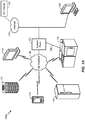
- FIG. 1A illustrates a high-level system architecture of a wireless communications system 100A in accordance with an aspect of the disclosure.
- the wireless communications system 100A contains a plurality of IoT devices, which include a television 110, an outdoor air conditioning unit 112, a thermostat 114, a refrigerator 116, and a washer and dryer 118.
- IoT devices 110-118 are configured to communicate with an access network (e.g., an access point 125) over a physical communications interface or layer, shown in FIG. 1A as air interface 108 and a direct wired connection 109.
- the air interface 108 can comply with a wireless Internet protocol (IP), such as IEEE 802.11.
- IP wireless Internet protocol
- FIG. 1A illustrates IoT devices 110-118 communicating over the air interface 108 and IoT device 118 communicating over the wired connection 109, each IoT device may communicate over a wired or wireless connection, or both.
- the Internet 175 includes a number of routing agents and processing agents (not shown in FIG. 1A for the sake of convenience).
- the Internet 175 is a global system of interconnected computers and computer networks that uses a standard Internet protocol suite (e.g., the Transmission Control Protocol (TCP) and IP) to communicate among disparate devices/networks.
- TCP/IP provides end-to-end connectivity specifying how data should be formatted, addressed, transmitted, routed and received at the destination.
- a computer 120 such as a desktop or personal computer (PC) is shown as connecting to the Internet 175 directly (e.g., over an Ethernet connection or Wi-Fi or 802.11-based network).
- the computer 120 may have a wired connection to the Internet 175, such as a direct connection to a modem or router, which, in an example, can correspond to the access point 125 itself (e.g., for a Wi-Fi router with both wired and wireless connectivity).
- the computer 120 may be connected to the access point 125 over air interface 108 or another wireless interface, and access the Internet 175 over the air interface.
- computer 120 may be a laptop computer, a tablet computer, a PDA, a smart phone, or the like.
- the computer 120 may be an IoT device and/or contain functionality to manage an IoT network/group, such as the network/group of IoT devices 110-118.
- the access point 125 may be connected to the Internet 175 via, for example, an optical communication system, such as FiOS, a cable modem, a digital subscriber line (DSL) modem, or the like.
- the access point 125 may communicate with IoT devices 110-118/120 and the Internet 175 using the standard Internet protocols (e.g., TCP/IP).
- an IoT server 170 is shown as connected to the Internet 175.
- the IoT server 170 can be implemented as a plurality of structurally separate servers, or alternately may correspond to a single server.
- the IoT server 170 is optional (as indicated by the dotted line), and the group of IoT devices 110-118/120 may be a peer-to-peer (P2P) network.
- P2P peer-to-peer
- the IoT devices 110-118/120 can communicate with each other directly over the air interface 108 and/or the wired connection 109.
- some or all of IoT devices 110-118/120 may be configured with a communication interface independent of air interface 108 and wired connection 109.
- the air interface 108 corresponds to a WiFi interface
- certain of the IoT devices 110-118/120 may have Bluetooth or NFC interfaces for communicating directly with each other or other Bluetooth or NFC-enabled devices.
- service discovery schemes can multicast the presence of nodes, their capabilities, and group membership.
- the peer-to-peer devices can establish associations and subsequent interactions based on this information.
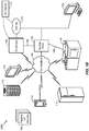
- FIG. 1B illustrates a high-level architecture of another wireless communications system 100B that contains a plurality of IoT devices.
- the wireless communications system 100B shown in FIG. 1B may include various components that are the same and/or substantially similar to the wireless communications system 100A shown in FIG.
- various IoT devices including a television 110, outdoor air conditioning unit 112, thermostat 114, refrigerator 116, and washer and dryer 118, that are configured to communicate with an access point 125 over an air interface 108 and/or a direct wired connection 109, a computer 120 that directly connects to the Internet 175 and/or connects to the Internet through access point 125, and an IoT server 170 accessible via the Internet 175, etc.
- IoT devices including a television 110, outdoor air conditioning unit 112, thermostat 114, refrigerator 116, and washer and dryer 118, that are configured to communicate with an access point 125 over an air interface 108 and/or a direct wired connection 109, a computer 120 that directly connects to the Internet 175 and/or connects to the Internet through access point 125, and an IoT server 170 accessible via the Internet 175, etc.
- FIG. 1B various details relating to certain components in the wireless communications system 100B shown in FIG. 1B may be omitted herein to the extent that the same or similar details have already been
- the wireless communications system 100B may include a supervisor device 130 that may be used to observe, monitor, control, or otherwise manage the various other components in the wireless communications system 100B.
- the supervisor device 130 can communicate with an access network (e.g., access point 125) over air interface 108 and/or a direct wired connection 109 to monitor or manage attributes, activities, or other states associated with the various IoT devices 110-118/120 in the wireless communications system 100B.
- the supervisor device 130 may have a wired or wireless connection to the Internet 175 and optionally to the IoT server 170 (shown as a dotted line).
- the supervisor device 130 may obtain information from the Internet 175 and/or the IoT server 170 that can be used to further monitor or manage attributes, activities, or other states associated with the various IoT devices 110-118/120.
- the supervisor device 130 may be a standalone device or one of IoT devices 110-118/120, such as computer 120.
- the supervisor device 130 may be a physical device or a software application running on a physical device.
- the supervisor device 130 may include a user interface that can output information relating to the monitored attributes, activities, or other states associated with the IoT devices 110-118/120 and receive input information to control or otherwise manage the attributes, activities, or other states associated therewith.
- the supervisor device 130 may generally include various components and support various wired and wireless communication interfaces to observe, monitor, control, or otherwise manage the various components in the wireless communications system 100B.
- the wireless communications system 100B shown in FIG. 1B may include one or more passive IoT devices 105 (in contrast to the active IoT devices 110-118/120) that can be coupled to or otherwise made part of the wireless communications system 100B.
- the passive IoT devices 105 may include barcoded devices, Bluetooth devices, radio frequency (RF) devices, RFID tagged devices, infrared (IR) devices, NFC tagged devices, or any other suitable device that can provide its identifier and attributes to another device when queried over a short range interface.
- Active IoT devices may detect, store, communicate, act on, and/or the like, changes in attributes of passive IoT devices.
- passive IoT devices 105 may include a coffee cup and a container of orange juice that each have an RFID tag or barcode.
- a cabinet IoT device and the refrigerator IoT device 116 may each have an appropriate scanner or reader that can read the RFID tag or barcode to detect when the coffee cup and/or the container of orange juice passive IoT devices 105 have been added or removed.
- the supervisor device 130 may receive one or more signals that relate to the activities detected at the cabinet IoT device and the refrigerator IoT device 116. The supervisor device 130 may then infer that a user is drinking orange juice from the coffee cup and/or likes to drink orange juice from a coffee cup.
- the passive IoT devices 105 may include one or more devices or other physical objects that do not have such communication capabilities.
- certain IoT devices may have appropriate scanner or reader mechanisms that can detect shapes, sizes, colors, and/or other observable features associated with the passive IoT devices 105 to identify the passive IoT devices 105.
- any suitable physical object may communicate its identity and attributes and become part of the wireless communication system 100B and be observed, monitored, controlled, or otherwise managed with the supervisor device 130.
- passive IoT devices 105 may be coupled to or otherwise made part of the wireless communications system 100A shown in FIG. 1A and observed, monitored, controlled, or otherwise managed in a substantially similar manner.
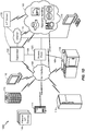
- FIG. 1C illustrates a high-level architecture of another wireless communications system 100C that contains a plurality of IoT devices.
- the wireless communications system 100C shown in FIG. 1C may include various components that are the same and/or substantially similar to the wireless communications systems 100A and 100B shown in FIGS. 1A and 1B , respectively, which were described in greater detail above.
- various details relating to certain components in the wireless communications system 100C shown in FIG. 1C may be omitted herein to the extent that the same or similar details have already been provided above in relation to the wireless communications systems 100A and 100B illustrated in FIGS. 1A and 1B , respectively.
- the communications system 100C shown in FIG. 1C illustrates exemplary peer-to-peer communications between the IoT devices 110-118 and the supervisor device 130.
- the supervisor device 130 communicates with each of the IoT devices 110-118 over an IoT supervisor interface.
- IoT devices 110 and 114, IoT devices 112, 114, and 116, and IoT devices 116 and 118 communicate directly with each other.
- the IoT devices 110-118 make up a proximal IoT group 160.
- a proximal IoT group is a group of locally connected IoT devices, such as the IoT devices connected to a user's home network.
- multiple proximal IoT groups may be connected to and/or communicate with each other via an IoT SuperAgent 140 connected to the Internet 175.
- the supervisor device 130 manages intra-group communications, while the IoT SuperAgent 140 can manage inter-group communications.
- the supervisor 130 and the IoT SuperAgent 140 may be, or reside on, the same device. This may be a standalone device or an IoT device, such as computer 120 in FIG. 1A .
- the IoT SuperAgent 140 may correspond to or include the functionality of the access point 125.
- the IoT SuperAgent 140 may correspond to or include the functionality of an IoT server, such as IoT server 170.
- the IoT SuperAgent 140 may encapsulate gateway functionality 145.
- Each IoT device 110-118 can treat the supervisor device 130 as a peer and transmit attribute/schema updates to the supervisor device 130.
- an IoT device needs to communicate with another IoT device, it can request the pointer to that IoT device from the supervisor device 130 and then communicate with the target IoT device as a peer.
- the IoT devices 110-118 communicate with each other over a peer-to-peer communication network using a common messaging protocol (CMP). As long as two IoT devices are CMP-enabled and connected over a common communication transport, they can communicate with each other.
- CMP common messaging protocol
- the CMP layer 154 is below the application layer 152 and above the transport layer 156 and the physical layer 158.
- FIG. 1D illustrates a high-level architecture of another wireless communications system 100D that contains a plurality of IoT devices.
- the wireless communications system 100D shown in FIG. 1D may include various components that are the same and/or substantially similar to the wireless communications systems 100A-C shown in FIGS. 1-C , respectively, which were described in greater detail above.
- various details relating to certain components in the wireless communications system 100D shown in FIG. 1D may be omitted herein to the extent that the same or similar details have already been provided above in relation to the wireless communications systems 100A-C illustrated in FIGS. 1A-C , respectively.
- the Internet is a "resource” that can be regulated using the concept of the IoT.
- the Internet is just one example of a resource that is regulated, and any resource could be regulated using the concept of the IoT.
- Other resources that can be regulated include, but are not limited to, electricity, gas, storage, security, and the like.
- An IoT device may be connected to the resource and thereby regulate it, or the resource could be regulated over the Internet.
- FIG. 1D illustrates several resources 180, such as natural gas, gasoline, hot water, and electricity, that can be regulated in addition to the Internet 175, or that can be regulated over the Internet 175.
- IoT devices can communicate with each other to regulate their use of a resource.
- IoT devices such as a toaster, a computer, and a hairdryer may communicate with each other over a Bluetooth communication interface to regulate their use of electricity (the resource).
- IoT devices such as a desktop computer, a telephone, and a tablet computer may communicate over a WiFi communication interface to regulate their access to the Internet (the resource).
- IoT devices such as a stove, a clothes dryer, and a water heater may communicate over a WiFi communication interface to regulate their use of gas.
- each IoT device may be connected to an IoT server, such as IoT server 170, that has logic to regulate their use of the resource based on information received from the IoT devices.
- FIG. 1E illustrates a high-level architecture of another wireless communications system 100E that contains a plurality of IoT devices.
- the wireless communications system 100E shown in FIG. 1E may include various components that are the same and/or substantially similar to the wireless communications systems 100A-D shown in FIGS. 1-D , respectively, which were described in greater detail above.
- various details relating to certain components in the wireless communications system 100E shown in FIG. 1E may be omitted herein to the extent that the same or similar details have already been provided above in relation to the wireless communications systems 100A-D illustrated in FIGS. 1A-D , respectively.
- the communications system 100E includes two proximal IoT groups 160A and 160B. Multiple proximal IoT groups may be connected to and/or communicate with each other via an IoT SuperAgent connected to the Internet 175. At a high level, an IoT SuperAgent manages inter-group communications.
- the proximal IoT group 160A includes IoT devices 116A, 122A, and 124A and an IoT SuperAgent 140A.
- the proximal IoT group 160B includes IoT devices 116B, 122B, and 124B and an IoT SuperAgent 140B. IoT SuperAgents 140A and 140B are connected to Internet 175 and may communicate with each other over the Internet 175 or directly.
- the IoT SuperAgents 140A and 140B facilitate communication between the proximal IoT groups 160A and 160B.
- FIG. 1E illustrates two proximal IoT groups communicating with each other via IoT SuperAgents 160A and 160B, any number of proximal IoT groups may communicate with each other using IoT SuperAgents.
- FIG. 2A illustrates a high-level example of an IoT device 200A in accordance with aspects of the disclosure. While external appearances and/or internal components can differ significantly among IoT devices, most IoT devices will have some sort of user interface, which may comprise a display and a means for user input. IoT devices without a user interface can be communicated with remotely over a wired or wireless network, such as air interface 108 in FIGS. 1A-B and D .
- a wired or wireless network such as air interface 108 in FIGS. 1A-B and D .
- an external casing of IoT device 200A may be configured with a display 226, a power button 222, and two control buttons 224A and 224B, among other components, as is known in the art.
- the display 226 may be a touchscreen display, in which case the control buttons 224A and 224B may not be necessary.
- the IoT device 200A may include one or more external antennas and/or one or more integrated antennas that are built into the external casing, including but not limited to Wi-Fi antennas, cellular antennas, satellite position system (SPS) antennas (e.g., global positioning system (GPS) antennas), and so on.
- Wi-Fi antennas e.g., Wi-Fi
- cellular antennas e.g., cellular antennas
- SPS satellite position system
- GPS global positioning system
- IoT device 200A While internal components of IoT devices, such as IoT device 200A, can be embodied with different hardware configurations, a basic high-level configuration for internal hardware components is shown as platform 202 in FIG. 2A .
- the platform 202 can receive and execute software applications, data and/or commands transmitted over a network interface, such as air interface 108 in FIGS. 1A-B and D and/or a wired interface.
- the platform 202 can also independently execute locally stored applications.
- the platform 202 can include one or more transceivers 206 configured for wired and/or wireless communication (e.g., a Wi-Fi transceiver, a Bluetooth transceiver, a cellular transceiver, a satellite transceiver, a GPS or SPS receiver, etc.) operably coupled to one or more processors 208, such as a microcontroller, microprocessor, application specific integrated circuit, digital signal processor (DSP), programmable logic circuit, or other data processing device, which will be generally referred to as processor 208.
- the processor 208 can execute application programming instructions within a memory 212 of the IoT device.
- the memory 212 can include one or more of read-only memory (ROM), random-access memory (RAM), electrically erasable programmable ROM (EEPROM), flash cards, or any memory common to computer platforms.
- ROM read-only memory
- RAM random-access memory
- EEPROM electrically erasable programmable ROM
- flash cards or any memory common to computer platforms.
- I/O interfaces 214 can be configured to allow the processor 208 to communicate with and control from various I/O devices such as the display 226, power button 222, control buttons 224A and 224B as illustrated, and any other devices, such as sensors, actuators, relays, valves, switches, and the like associated with the IoT device 200A.
- an aspect of the disclosure can include an IoT device (e.g., IoT device 200A) including the ability to perform the functions described herein.
- IoT device 200A IoT device 200A
- the various logic elements can be embodied in discrete elements, software modules executed on a processor (e.g., processor 208) or any combination of software and hardware to achieve the functionality disclosed herein.
- transceiver 206, processor 208, memory 212, and I/O interface 214 may all be used cooperatively to load, store and execute the various functions disclosed herein and thus the logic to perform these functions may be distributed over various elements.
- the functionality could be incorporated into one discrete component. Therefore, the features of the IoT device 200A in FIG. 2A are to be considered merely illustrative and the disclosure is not limited to the illustrated features or arrangement.
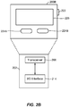
- FIG. 2B illustrates a high-level example of a passive IoT device 200B in accordance with aspects of the disclosure.
- the passive IoT device 200B shown in FIG. 2B may include various components that are the same and/or substantially similar to the IoT device 200A shown in FIG. 2A , which was described in greater detail above.
- various details relating to certain components in the passive IoT device 200B shown in FIG. 2B may be omitted herein to the extent that the same or similar details have already been provided above in relation to the IoT device 200A illustrated in FIG. 2A .
- the passive IoT device 200B shown in FIG. 2B may generally differ from the IoT device 200A shown in FIG. 2A in that the passive IoT device 200B may not have a processor, internal memory, or certain other components. Instead, in one embodiment, the passive IoT device 200A may only include an I/O interface 214 or other suitable mechanism that allows the passive IoT device 200B to be observed, monitored, controlled, managed, or otherwise known within a controlled IoT network.
- the I/O interface 214 associated with the passive IoT device 200B may include a barcode, Bluetooth interface, radio frequency (RF) interface, RFID tag, IR interface, NFC interface, or any other suitable I/O interface that can provide an identifier and attributes associated with the passive IoT device 200B to another device when queried over a short range interface (e.g., an active IoT device, such as IoT device 200A, that can detect, store, communicate, act on, or otherwise process information relating to the attributes associated with the passive IoT device 200B).
- RF radio frequency
- the passive IoT device 200B may comprises a device or other physical object that does not have such an I/O interface 214.
- certain IoT devices may have appropriate scanner or reader mechanisms that can detect shapes, sizes, colors, and/or other observable features associated with the passive IoT device 200B to identify the passive IoT device 200B.
- any suitable physical object may communicate its identity and attributes and be observed, monitored, controlled, or otherwise managed within a controlled IoT network.
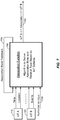
- FIG. 3 illustrates a communication device 300 that includes logic configured to perform functionality.
- the communication device 300 can correspond to any of the above-noted communication devices, including but not limited to IoT devices 110-118/120, IoT device 200, any components coupled to the Internet 175 (e.g., the IoT server 170), and so on.
- communication device 300 can correspond to any electronic device that is configured to communicate with (or facilitate communication with) one or more other entities over the wireless communications systems 100A-E of FIGS. 1A-E .
- FIG. 3 illustrates a communication device 300 that includes logic configured to perform functionality.
- the communication device 300 can correspond to any of the above-noted communication devices, including but not limited to IoT devices 110-118/120, IoT device 200A, any components coupled to the Internet 175 (e.g., the IoT server 170), and so on.
- communication device 300 can correspond to any electronic device that is configured to communicate with (or facilitate communication with) one or more other entities over the wireless communications systems 100A-E of FIGS. 1A-E .
- the communication device 300 includes logic configured to receive and/or transmit information 305.
- the logic configured to receive and/or transmit information 305 can include a wireless communications interface (e.g., Bluetooth, Wi-Fi, Wi-Fi Direct, Long-Term Evolution (LTE) Direct, etc.) such as a wireless transceiver and associated hardware (e.g., an RF antenna, a MODEM, a modulator and/or demodulator, etc.).
- a wireless communications interface e.g., Bluetooth, Wi-Fi, Wi-Fi Direct, Long-Term Evolution (LTE) Direct, etc.
- LTE Long-Term Evolution
- the logic configured to receive and/or transmit information 305 can correspond to a wired communications interface (e.g., a serial connection, a USB or Firewire connection, an Ethernet connection through which the Internet 175 can be accessed, etc.).
- a wired communications interface e.g., a serial connection, a USB or Firewire connection, an Ethernet connection through which the Internet 175 can be accessed, etc.
- the communication device 300 corresponds to some type of network-based server (e.g., the IoT server 170)
- the logic configured to receive and/or transmit information 305 can correspond to an Ethernet card, in an example, that connects the network-based server to other communication entities via an Ethernet protocol.
- the logic configured to receive and/or transmit information 305 may include logic configured to receive, at a first IoT device, an identifier of a second IoT device, and logic configured to obtain, by the first IoT device, a schema for the second IoT device based on the identifier of the second IoT device.
- the logic configured to receive and/or transmit information 305 can include sensory or measurement hardware by which the communication device 300 can monitor its local environment (e.g., an accelerometer, a temperature sensor, a light sensor, an antenna for monitoring local RF signals, etc.).
- the logic configured to receive and/or transmit information 305 can also include software that, when executed, permits the associated hardware of the logic configured to receive and/or transmit information 305 to perform its reception and/or transmission function(s). However, the logic configured to receive and/or transmit information 305 does not correspond to software alone, and the logic configured to receive and/or transmit information 305 relies at least in part upon hardware to achieve its functionality.
- the communication device 300 further includes logic configured to process information 310.
- the logic configured to process information 310 can include at least a processor.
- Example implementations of the type of processing that can be performed by the logic configured to process information 310 includes but is not limited to performing determinations, establishing connections, making selections between different information options, performing evaluations related to data, interacting with sensors coupled to the communication device 300 to perform measurement operations, converting information from one format to another (e.g., between different protocols such as .wmv to .avi, etc.), and so on.
- the logic configured to process information 310 may include logic configured to receive, at a first IoT device, an identifier of a second IoT device, logic configured to obtain, by the first IoT device, a schema for the second IoT device based on the identifier of the second IoT device, and logic configured to determine, by the first IoT device, whether or not there is an association between the first IoT device and the second IoT device based on a schema of the first IoT device and the schema of the second IoT device.
- the processor included in the logic configured to process information 310 can correspond to a general purpose processor, a DSP, an ASIC, a field programmable gate array (FPGA) or other programmable logic device, discrete gate or transistor logic, discrete hardware components, or any combination thereof designed to perform the functions described herein.
- a general purpose processor may be a microprocessor, but in the alternative, the processor may be any conventional processor, controller, microcontroller, or state machine.
- a processor may also be implemented as a combination of computing devices (e.g., a combination of a DSP and a microprocessor, a plurality of microprocessors, one or more microprocessors in conjunction with a DSP core, or any other such configuration).
- the logic configured to process information 310 can also include software that, when executed, permits the associated hardware of the logic configured to process information 310 to perform its processing function(s). However, the logic configured to process information 310 does not correspond to software alone, and the logic configured to process information 310 relies at least in part upon hardware to achieve its functionality.
- the communication device 300 further includes logic configured to store information 315.
- the logic configured to store information 315 can include at least a non-transitory memory and associated hardware (e.g., a memory controller, etc.).
- the non-transitory memory included in the logic configured to store information 315 can correspond to RAM, flash memory, ROM, erasable programmable ROM (EPROM), EEPROM, registers, hard disk, a removable disk, a CD-ROM, or any other form of storage medium known in the art.
- the logic configured to store information 315 can also include software that, when executed, permits the associated hardware of the logic configured to store information 315 to perform its storage function(s). However, the logic configured to store information 315 does not correspond to software alone, and the logic configured to store information 315 relies at least in part upon hardware to achieve its functionality.
- the communication device 300 further optionally includes logic configured to present information 320.
- the logic configured to present information 320 can include at least an output device and associated hardware.
- the output device can include a video output device (e.g., a display screen, a port that can carry video information such as USB, HDMI, etc.), an audio output device (e.g., speakers, a port that can carry audio information such as a microphone jack, USB, HDMI, etc.), a vibration device and/or any other device by which information can be formatted for output or actually outputted by a user or operator of the communication device 300.
- a video output device e.g., a display screen, a port that can carry video information such as USB, HDMI, etc.
- an audio output device e.g., speakers, a port that can carry audio information such as a microphone jack, USB, HDMI, etc.
- a vibration device e.g., a vibration device and/or any other device by which information can be formatted for output or actually outputted by
- the logic configured to present information 320 can include the display 226.
- the logic configured to present information 320 can be omitted for certain communication devices, such as network communication devices that do not have a local user (e.g., network switches or routers, remote servers, etc.).
- the logic configured to present information 320 can also include software that, when executed, permits the associated hardware of the logic configured to present information 320 to perform its presentation function(s).
- the logic configured to present information 320 does not correspond to software alone, and the logic configured to present information 320 relies at least in part upon hardware to achieve its functionality.
- the communication device 300 further optionally includes logic configured to receive local user input 325.
- the logic configured to receive local user input 325 can include at least a user input device and associated hardware.
- the user input device can include buttons, a touchscreen display, a keyboard, a camera, an audio input device (e.g., a microphone or a port that can carry audio information such as a microphone jack, etc.), and/or any other device by which information can be received from a user or operator of the communication device 300.
- the communication device 300 corresponds to the IoT device 200A as shown in FIG. 2A and/or the passive IoT device 200B as shown in FIG.
- the logic configured to receive local user input 325 can include the buttons 222, 224A, and 224B, the display 226 (if a touchscreen), etc.
- the logic configured to receive local user input 325 can be omitted for certain communication devices, such as network communication devices that do not have a local user (e.g., network switches or routers, remote servers, etc.).
- the logic configured to receive local user input 325 can also include software that, when executed, permits the associated hardware of the logic configured to receive local user input 325 to perform its input reception function(s).
- the logic configured to receive local user input 325 does not correspond to software alone, and the logic configured to receive local user input 325 relies at least in part upon hardware to achieve its functionality.
- any software used to facilitate the functionality of the configured logics of 305 through 325 can be stored in the non-transitory memory associated with the logic configured to store information 315, such that the configured logics of 305 through 325 each performs their functionality (i.e., in this case, software execution) based in part upon the operation of software stored by the logic configured to store information 315.
- hardware that is directly associated with one of the configured logics can be borrowed or used by other configured logics from time to time.
- the processor of the logic configured to process information 310 can format data into an appropriate format before being transmitted by the logic configured to receive and/or transmit information 305, such that the logic configured to receive and/or transmit information 305 performs its functionality (i.e., in this case, transmission of data) based in part upon the operation of hardware (i.e., the processor) associated with the logic configured to process information 310.
- logic configured to as used throughout this disclosure is intended to invoke an aspect that is at least partially implemented with hardware, and is not intended to map to software-only implementations that are independent of hardware.
- the configured logic or “logic configured to” in the various blocks are not limited to specific logic gates or elements, but generally refer to the ability to perform the functionality described herein (either via hardware or a combination of hardware and software).
- the configured logics or “logic configured to” as illustrated in the various blocks are not necessarily implemented as logic gates or logic elements despite sharing the word “logic.” Other interactions or cooperation between the logic in the various blocks will become clear to one of ordinary skill in the art from a review of the aspects described below in more detail.
- the server 400 may correspond to one example configuration of the IoT server 170 described above.
- the server 400 includes a processor 400 coupled to volatile memory 402 and a large capacity nonvolatile memory, such as a disk drive 403.
- the server 400 may also include a floppy disc drive, compact disc (CD) or DVD disc drive 406 coupled to the processor 401.
- the server 400 may also include network access ports 404 coupled to the processor 401 for establishing data connections with a network 407, such as a local area network coupled to other broadcast system computers and servers or to the Internet.
- a network 407 such as a local area network coupled to other broadcast system computers and servers or to the Internet.
- the server 400 of FIG. 4 illustrates one example implementation of the communication device 300, whereby the logic configured to transmit and/or receive information 305 corresponds to the network access points 404 used by the server 400 to communicate with the network 407, the logic configured to process information 310 corresponds to the processor 401, and the logic configuration to store information 315 corresponds to any combination of the volatile memory 402, the disk drive 403 and/or the disc drive 406.
- the optional logic configured to present information 320 and the optional logic configured to receive local user input 325 are not shown explicitly in FIG. 4 and may or may not be included therein.
- FIG. 4 helps to demonstrate that the communication device 300 may be implemented as a server, in addition to an IoT device implementation as in FIG. 2A .
- IP based technologies and services have become more mature, driving down the cost and increasing availability of IP.
- the IoT is based on the idea that everyday electronic objects, not just computers and computer networks, can be readable, recognizable, locatable, addressable, and controllable via the Internet.
- an aspect of the disclosure provides a generic IoT universal schema that defines all facets of IoT device interaction (with minimal configuration and integration) and makes discovery, interaction, association, and collaboration among heterogeneous IoT devices and/or networks feasible.
- the universal schema is a generic, simple, extensible universal schema for IoT devices that simplifies interaction among heterogeneous IoT devices.
- the universal schema has several characteristics.
- the universal schema is logically a Singleton instance. It defines a comprehensive list of schema elements, the syntax and semantics of element name-value pairs, and the mandatory elements for a device category. It is adaptive and extensible.
- the universal schema is the absolute superset of schema elements applicable and usable for any given IoT device. There are two core aspects pertinent to the schema for any given IoT device and thus applicable to the universal schema: adaptability and extensibility.
- the universal schema is an adaptive schema, in that schema values can evolve based on learning from the environment and discovering and interacting with other IoT devices. It is an extensible schema, in that constructs allow for adding new schema elements to an existing IoT schema.
- the schema for a given IoT device is a subset of the universal schema, and includes attributes of the IoT device that enable it to interact with other IoT devices.
- An IoT device's subset of schema elements of the universal schema may be referred to as a "mask,” and is an instantiation of the universal schema for a particular IoT device. It is the functionality that is exposed by the set of name-value pairs of the subset of schema elements. Because the universal schema is adaptive and extensible, the same hardware and/or software could expose a different device "mask" over time.
- Each original equipment manufacturer can implement schema-compliant IoT devices.
- the IoT device mask can be factory flashed.
- an IoT device(s) can retrieve its/their device mask(s) from a database.
- Schema element values provide adaptability. Schema element values can adapt to the context, environment, and the like, of an IoT device based on self-learning and communication with other IoT devices. As a result, schema element values acquire a dynamic nature whereby the schema element values can evolve based on the aforementioned factors.
- the "Association List" schema element values for a refrigerator IoT device can expand or contract based on new IoT devices entering or leaving the refrigerator's shared resources ecosystem.
- the "Status" for a light bulb IoT device can change from "Luminosity: 110 Lumens” to "Luminosity: 80 Lumens” based on an increase in the ambient light and the corresponding need to shift to a lower luminosity setting.
- Schema elements provide extensibility. Schema elements can be augmented, meaning that new Schema Elements can be defined and associated for any given IoT device, which thereby augments the universal schema. Extensibility is a precursor for adaptability for a new schema element, but adaptability of existing schema elements is independent of extensibility. In other words, extensibility introduces a new schema element, which becomes a candidate for adaptability.
- Extensibility can be achieved by upgrading the hardware and/or software of an IoT device and augmenting the existing schema element set.
- a functionality F exists on an IoT device but the schema element(s) that exposes/introduces that functionality is not defined in the IoT device's Schema.
- its schema element set needs to be augmented to introduce the new schema element(s) associated with functionality F.
- This newly "extended" Schema Element(s) may start out with a NULL/non-initialized value, and can then "adapt" to its context/environment to determine the schema element value(s).
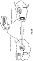
- FIG. 5 illustrates exemplary IoT networks that include IoT devices that can communicate with each other and/or a remote server.
- An exemplary IoT network 510 includes an IoT device 512 (illustrated as a microwave), an IoT device 514 (illustrated as a smart phone), and an IoT device 516 (illustrated as a vacuuming robot).
- An exemplary IoT network 520 includes an IoT device 522 (illustrated as a programmable thermostat), an IoT device 524 (illustrated as a smart phone), and an IoT device 526 (illustrated as a vacuuming robot).
- these are merely examples of IoT networks and IoT devices, and the disclosure is not limited to these examples.
- the IoT devices within the IoT networks 510 and 520 can communicate with a server 550.
- the server 550 may be an application server, such as IoT server 170 in FIG. 1A , or a computer, such as computer 120 in FIG. 1A .
- IoT networks 510 and 520 may be disparate IoT networks belonging to different users at different locations. In that case, server 550 may be an application server in communication with a number of such disparate IoT networks.
- IoT networks 510 and 520 may be IoT networks operated by, belonging to, and/or related to the same user. In that case, server 550 may be a personal computer in communication with only those IoT networks associated with the user.
- the server 550 stores an IoT universal schema 552.
- Each IoT device 512, 514, 516, 522, 524, and 526 has its own schema, or "mask,” that is a subset of the IoT universal schema 552. This sub-schema/mask provides the vocabulary of an IoT device.
- Each IoT device can be assigned a GUID.
- GUIDs can be used as pointers to the IoT device schema/mask in the IoT universal schema 552.
- the schema for an IoT device can be stored at the server 550, and an IoT device can use a GUID to obtain the corresponding schema/mask from the IoT universal schema 552.
- the entire universal schema for an IoT device can be stored/cached on the IoT device itself. This allows the IoT device to access a particular IoT device's schema without connecting to server 550.
- IoT device 516 and IoT device 522 wish to communicate with each other. Accordingly, IoT device 516 and IoT device 522 exchange their respective GUIDs, shown as "I am GUID-A" and "I am GUID-B" messages, respectively.
- IoT device 516 Once IoT device 516 has the GUID of IoT device 522, it can query the server 550 with the GUID to fetch the schema for IoT device 522.
- IoT device 522 has the GUID of IoT device 516, it can query the server 550 with the GUID to fetch the schema for IoT device 516.
- IoT devices 516 and 522 have each other's respective schemas, they can interact with each other as defined in their respective schemas.
- FIG. 6 illustrates an exemplary flow of providing a universal schema, such as IoT universal schema 552 in FIG. 5 , for heterogeneous IoT devices.
- the flow illustrated in FIG. 6 may be performed by an IoT device, such as any of IoT devices 110-118 of FIGS. 1A-D , IoT devices 116A-124A or 116B-124B of FIG. 1E , IoT device 200A in FIG. 2A , communication device 300 in FIG. 3 , or IoT devices 512-516 or 522-526 of FIG. 5 .
- the IoT device receives a schema that includes a plurality of schema elements.
- the received schema may be a subset, or mask, of the universal schema.
- the IoT device may receive the schema from an IoT server, such as IoT server 170 in FIG. 1A , a supervisor device, such as supervisor device 130 in FIG. 1B , an OEM (by storing the schema in the memory of the IoT device), from a remote server over the Internet, another IoT device, or the like.
- the IoT device receives or determines one or more schema element values for each of the plurality of schema elements.
- the schema element values may be received in the same or similar way as the schema, that is, from an IoT server, a supervisor device, an OEM, a remote server, another IoT device, or the like. Additionally, at least some of the schema element values may be determined or updated dynamically. For example, certain schema element values may be determined or updated based on the context, environment, and/or the like, of the IoT device.
- the IoT device transmits an identifier, such as a GUID, to a remote IoT device.
- the IoT device receives an identifier, such as a GUID, from the remote IoT device.
- the IoT device may optionally transmit the GUID of the remote IoT device to a remote server, such as server 550, to obtain the schema/mask for the remote IoT device.
- a remote server such as server 550
- each IoT device may store its own schema and provide it to requesting IoT devices.
- an IoT device may send its schema along with, or in a separate transmission from, its GUID.
- the IoT device receives the schema for the remote IoT device, either from the remote server, internal memory, or the remote IoT device.
- the schema provides the vocabulary of the remote IoT device, allowing the IoT devices to interact with each other.
- the remote IoT device performs a similar process to obtain the schema of the first IoT device.
- the IoT devices can determine whether or not there is an association between them, and if there is, then at 670, the IoT devices are able to interact with each other based on the obtained schemas/association.
- IoT devices In order to be able to interact with each other, IoT devices first need to form associations. Association lists, association ranks, and/or inter-dependencies among IoT devices can be leveraged to ascertain and establish a degree of confidence of associations among IoT devices.
- Example scenarios where associations are formed include where a new IoT device is introduced to an existing set of associated IoT devices, or where an IoT device dynamically re-creates or re-evaluates (e.g., strengthens, dilutes, etc.) associations and association degrees.
- the schema of an IoT device can be leveraged to establish associations.
- IoT_NewSprinkler may have an IoT_WaterPump in its association list from a factory flashed initial mask AND the IoT device IoT_WaterPump may have an IoTPoolFilter in its association list from provisioning. This implies that IoT_NewSprinkler can establish an association with IoT_PoolFilter.
- the "Association" schema element may include three tuples: ⁇ Source IoT Device OR IoT Group>, ⁇ Destination IoT Device OR IoT Group>, and ⁇ Association Basis>.
- the Association Basis identifies the commonality, dependency, or the basis of the relationship between the Source and Destination IoT Devices or IoT Groups. Associations may be further qualified by the Session and State of Association, the Degree of Association, the Uses (e.g., IoT Washer Uses IoT Water Heater), and IsUsedBy (e.g., IoT Refrigerator isUsedBy IoT Water Dispenser).
- FIG. 7 illustrates an exemplary association function 700 receiving inputs from two IoT devices, IoT device A 710 and IoT device B 720.
- the association function 700 is an algorithm to derive an association rank and relation type based on the schemas of two or more IoT devices, here, IoT devices A 710 and B 720.
- the association function 700 receives time and location schema element values from IoT device A 710, events element values from IoT B 720, and (optionally) authoritative/overriding input 730. Based on these received schema elements/values, the association function 700 is able to output an association 740 between IoT device A 710 and IoT device B 720. The association function 700 can also provide association rank feedback 750 to itself.
- a degree of association (referred to as the association rank feedback 750) is also one of the inputs for determining the association between IoT devices A 710 and B720.
- the initial value of the degree of association may start out as zero.
- the feedback path enables the degree of association to be re-evaluated with time or changes in environment, context, events, etc. As a result, the derived degree of association could be amplified or attenuated.
- the degree of association is part of the IoT device's schema.
- the authoritative input 730 is an ancillary input to the association function 700.
- the authoritative input 730 can come from the authoritative owner of the IoT ecosystem or from any higher ranking IoT device and can supersede, override, nullify, or approve the association input, and/or influence or overthrow the outcome of the association function 700.
- FIG. 8 illustrates an exemplary IoT network 800 in which heterogeneous IoT devices form associations with each other based on patterns in their respective schemas.
- a newly introduced IoT device 810 illustrated as a clothes washer, introduces itself to the other IoT devices in the IoT network 800 by broadcasting an "I am ⁇ GUID-A>" message.
- a set of associated IoT devices 820, 830, and 840 illustrated as a dishwasher, a microwave, and a vacuuming robot, respectively, detect a spatial and temporal pattern of "I am ⁇ GUID-A>" introductions from the new IoT device 810.
- the IoT devices 820, 830, and 840 may retrieve the schema for IoT device 810 from a remote server, such as server 550 in FIG. 5 , as illustrated in FIG. 5 .
- a subset of IoT devices may detect an overlap in a set of IoT schema element values of its schema and the schema of the new IoT device 810, such as inputs, actions, capabilities, environment, etc.
- the IoT device 820 may then send an "I am ⁇ GUID-B>" introduction to the new IoT device 810, similar to the introduction illustrated in FIG. 5 .
- the IoT device 810 may retrieve the schema for IoT device 820 from the server 550, as illustrated in FIG. 5 .
- each IoT device in the IoT network 800 may exchange "I am ⁇ GUID>" messages, and each IoT device may detect overlapping IoT schema elements/values between itself and (an)other IoT device(s).
- the IoT devices 810 and 820 may discover an overlap in input, environment, and time elements. For example:
- the self-forming association function such as association function 700 in FIG. 7 , enable the associated IoT devices to establish confidence intervals, or degrees of "associativity," with the new IoT device. Based on a dynamic or preconfigured threshold and security policies, this "associativity" can be accepted or negated by each IoT device.
- a newly purchased coffee maker can send out an "I am ⁇ GUID>" broadcast to the user's watch, smartphone, shoes, automobile, home security system, thermostat, refrigerator, water heater, etc.
- IoT devices that identify an association pattern can accept or acknowledge the association by returning an "associativity" message to the new IoT device.
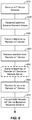
- FIG. 9A illustrates an exemplary flow for determining associations among IoT devices.
- the flow illustrated in FIG. 9A may be performed by a new IoT device, such as IoT device 810 in FIG. 8 .
- the new IoT device detects an IoT network for the first time.
- the new IoT device transmits its GUID to any other IoT devices on the IoT network, similar to 630 of FIG. 6 .
- the new IoT device receives a GUID from at least a second IoT device, similar to 640 of FIG. 6 .
- the second IoT device may have already determined an association between itself and the new IoT device and is transmitting its GUID in response, or the second IoT device may immediately transmit its GUID without determining an association.
- the new IoT device obtains the schema for the at least one second IoT device using the GUID of the second IoT device, similar to 650 and 660 of FIG. 6 .
- the new IoT device may obtain the schema from a remote server, such as server 550 in FIG. 5 , the second IoT device, a removable memory medium (such as a flash memory card), etc.
- the new IoT device determines the association(s) between itself and the at least one second IoT device by comparing its own schema and the schema of the second IoT device.
- the new IoT device may determine the association by identifying patterns in its schema that overlap patterns in the schema of the second IoT device.
- the IoT devices may then interact with each other based on the determined association, as in 670 of FIG. 6 .
- FIG. 9B illustrates an exemplary flow for determining associations among IoT devices performed at an IoT device already connected to an IoT network, such as IoT device 820 in FIG. 8 .
- the IoT device receives the GUID of a new IoT device, such as IoT device 810 in FIG. 8 .
- the IoT device obtains the schema of the new IoT device.
- the IoT device may obtain the schema from a remote server, such as server 550 in FIG. 5 , the new IoT device, a removable memory medium (such as a flash memory card), etc.
- the IoT device determines an association between itself and the new IoT device based on its own schema and the schema of the new IoT device.
- the IoT device may determine the association by identifying patterns in its schema that overlap patterns in the schema of the new IoT device.
- the IoT device optionally transmits its GUID to the new IoT device. If there is an association between the IoT devices, the IoT device can transmit its GUID to the new IoT device. If there is not an association, the IoT device can refrain from transmitting its GUID to the new IoT device. Alternatively, the IoT device can transmit its GUID to the new IoT device before determining whether or not there is an association.
- IoT devices that determine a confidence level in any identified associations can transmit the confidence level to the associated IoT device and/or a server or administrator for the IoT network.
- the server or administrator may be a remote third party server, a local user server, a local user device acting as an administrator for the IoT network, or the like.
- DSP digital signal processor
- ASIC application specific integrated circuit
- FPGA field programmable gate array
- a general purpose processor may be a microprocessor, but in the alternative, the processor may be any conventional processor, controller, microcontroller, or state machine.
- a processor may also be implemented as a combination of computing devices, e.g., a combination of a DSP and a microprocessor, a plurality of microprocessors, one or more microprocessors in conjunction with a DSP core, or any other such configuration.
- a software module may reside in RAM, flash memory, ROM, EPROM, EEPROM, registers, hard disk, a removable disk, a CD-ROM, or any other form of storage medium known in the art.
- An exemplary storage medium is coupled to the processor such that the processor can read information from, and write information to, the storage medium.
- the storage medium may be integral to the processor.
- the processor and the storage medium may reside in an ASIC.
- the ASIC may reside in an IoT device.
- the processor and the storage medium may reside as discrete components in a user terminal.
- the functions described may be implemented in hardware, software, firmware, or any combination thereof. If implemented in software, the functions may be stored on or transmitted over as one or more instructions or code on a computer-readable medium.
- Computer-readable media includes both computer storage media and communication media including any medium that facilitates transfer of a computer program from one place to another.
- a storage media may be any available media that can be accessed by a computer.
- such computer-readable media can comprise RAM, ROM, EEPROM, CD-ROM or other optical disk storage, magnetic disk storage or other magnetic storage devices, or any other medium that can be used to carry or store desired program code in the form of instructions or data structures and that can be accessed by a computer.
- any connection is properly termed a computer-readable medium.
- the software is transmitted from a website, server, or other remote source using a coaxial cable, fiber optic cable, twisted pair, DSL, or wireless technologies such as infrared, radio, and microwave
- the coaxial cable, fiber optic cable, twisted pair, DSL, or wireless technologies such as infrared, radio, and microwave are included in the definition of medium.
- Disk and disc includes CD, laser disc, optical disc, DVD, floppy disk and Blu-ray disc where disks usually reproduce data magnetically, while discs reproduce data optically with lasers. Combinations of the above should also be included within the scope of computer-readable media.
Landscapes
- Engineering & Computer Science (AREA)
- Computer Networks & Wireless Communication (AREA)
- Signal Processing (AREA)
- Automation & Control Theory (AREA)
- Health & Medical Sciences (AREA)
- General Health & Medical Sciences (AREA)
- Computing Systems (AREA)
- Medical Informatics (AREA)
- Theoretical Computer Science (AREA)
- Databases & Information Systems (AREA)
- Cardiology (AREA)
- Physics & Mathematics (AREA)
- General Physics & Mathematics (AREA)
- General Engineering & Computer Science (AREA)
- Data Mining & Analysis (AREA)
- Telephonic Communication Services (AREA)
- Selective Calling Equipment (AREA)
- Information Retrieval, Db Structures And Fs Structures Therefor (AREA)
- Computer And Data Communications (AREA)
- Mobile Radio Communication Systems (AREA)
Description
- The disclosure is related to providing an adaptive and extensible universal schema for heterogeneous Internet of Things (IoT) devices.
- The Internet is a global system of interconnected computers and computer networks that use a standard Internet protocol suite (e.g., the Transmission Control Protocol (TCP) and Internet Protocol (IP)) to communicate with each other. The Internet of Things (IoT) is based on the idea that everyday objects, not just computers and computer networks, can be readable, recognizable, locatable, addressable, and controllable via an IoT communications network (e.g., an ad-hoc system or the Internet).
- A number of market trends are driving development of IoT devices. For example, increasing energy costs are driving governments' strategic investments in smart grids and support for future consumption, such as for electric vehicles and public charging stations. Increasing health care costs and aging populations are driving development for remote/connected health care and fitness services. A technological revolution in the home is driving development for new "smart" services, including consolidation by service providers marketing 'N' play (e.g., data, voice, video, security, energy management, etc.) and expanding home networks. Buildings are getting smarter and more convenient as a means to reduce operational costs for enterprise facilities.
- There are a number of key applications for the IoT. For example, in the area of smart grids and energy management, utility companies can optimize delivery of energy to homes and businesses while customers can better manage energy usage. In the area of home and building automation, smart homes and buildings can have centralized control over virtually any device or system in the home or office, from appliances to plug-in electric vehicle (PEV) security systems. In the field of asset tracking, enterprises, hospitals, factories, and other large organizations can accurately track the locations of high-value equipment, patients, vehicles, and so on. In the area of health and wellness, doctors can remotely monitor patients' health while people can track the progress of fitness routines.
WO2011/112683 describes a method and apparatus for supporting machine to machine communications in a hierarchical network architecture including an M2M gateway. - The disclosure is related to determining an association among Internet of Things (IoT) devices. A method for determining an association among IoT devices includes receiving, at a first IoT device, an identifier of a second IoT device, obtaining, by the first IoT device, a schema of the second IoT device based on the identifier of the second IoT device, and determining, by the first IoT device, whether or not there is an association between the first IoT device and the second IoT device based on a schema of the first IoT device and the schema of the second IoT device, wherein the schema of the first IoT device comprises schema elements and corresponding values of the first IoT device and the schema of the second IoT device comprises schema elements and corresponding values of the second IoT device.
- An apparatus for determining an association among IoT devices includes logic configured to receive, at a first IoT device, an identifier of a second IoT device, logic configured to obtain, by the first IoT device, a schema of the second IoT device based on the identifier of the second IoT device, and logic configured to determine, by the first IoT device, whether or not there is an association between the first IoT device and the second IoT device based on a schema of the first IoT device and the schema of the second IoT device, wherein the schema of the first IoT device comprises schema elements and corresponding values of the first IoT device and the schema of the second IoT device comprises schema elements and corresponding values of the second IoT device.
- An apparatus for determining an association among IoT devices includes means for receiving, at a first IoT device, an identifier of a second IoT device, means for obtaining, by the first IoT device, a schema of the second IoT device based on the identifier of the second IoT device, and means for determining, by the first IoT device, whether or not there is an association between the first IoT device and the second IoT device based on a schema of the first IoT device and the schema of the second IoT device, wherein the schema of the first IoT device comprises schema elements and corresponding values of the first IoT device and the schema of the second IoT device comprises schema elements and corresponding values of the second IoT device.
- A non-transitory computer-readable medium for determining an association among IoT devices includes at least one instruction to receive, at a first IoT device, an identifier of a second IoT device, at least one instruction to obtain, by the first IoT device, a schema of the second IoT device based on the identifier of the second IoT device, and at least one instruction to determine, by the first IoT device, whether or not there is an association between the first IoT device and the second IoT device based on a schema of the first IoT device and the schema of the second IoT device, wherein the schema of the first IoT device comprises schema elements and corresponding values of the first IoT device and the schema of the second IoT device comprises schema elements and corresponding values of the second IoT device.
- A more complete appreciation of aspects of the disclosure and many of the attendant advantages thereof will be readily obtained as the same becomes better understood by reference to the following detailed description when considered in connection with the accompanying drawings which are presented solely for illustration and not limitation of the disclosure, and in which:
-
FIG. 1A illustrates a high-level system architecture of a wireless communications system in accordance with an aspect of the disclosure. -
FIG. 1B illustrates a high-level system architecture of a wireless communications system in accordance with an aspect of the disclosure. -
FIG. 1C illustrates a high-level system architecture of a wireless communications system in accordance with an aspect of the disclosure. -
FIG. 1D illustrates a high-level system architecture of a wireless communications system in accordance with an aspect of the disclosure. -
FIG. 1E illustrates a high-level system architecture of a wireless communications system in accordance with an aspect of the disclosure. -
FIG. 2A illustrates an exemplary Internet of Things (IoT) device in accordance with aspects of the disclosure, whileFIG. 2B illustrates an exemplary passive IoT device in accordance with aspects of the disclosure. -
FIG. 3 illustrates a communication device that includes logic configured to perform functionality in accordance with an aspect of the disclosure. -
FIG. 4 illustrates an exemplary server according to various aspects of the disclosure. -
FIG. 5 illustrates exemplary IoT networks including IoT devices that can communicate with each other and/or a remote server. -
FIG. 6 illustrates an exemplary flow for communicating among IoT devices. -
FIG. 7 illustrates an exemplary association function receiving inputs from two IoT devices. -
FIG. 8 illustrates an exemplary IoT network in which heterogeneous IoT devices form associations with each other based on patterns in their respective identity profiles. -
FIG. 9A illustrates an exemplary flow for determining associations among IoT devices performed at a new IoT device. -
FIG. 9B illustrates an exemplary flow for determining associations among IoT devices performed at an IoT device already connected to an IoT network. - Various aspects of the disclosure are disclosed in the following description and related drawings. Alternate aspects may be devised without departing from the scope of the disclosure. Additionally, well-known elements of the disclosure will not be described in detail or will be omitted so as not to obscure the relevant details of the disclosure.
- The words "exemplary" and/or "example" are used herein to mean "serving as an example, instance, or illustration." Any aspect described herein as "exemplary" and/or "example" is not necessarily to be construed as preferred or advantageous over other aspects. Likewise, the term "aspects of the disclosure" does not require that all aspects of the disclosure include the discussed feature, advantage or mode of operation.
- Further, many aspects are described in terms of sequences of actions to be performed by, for example, elements of a computing device. It will be recognized that various actions described herein can be performed by specific circuits (e.g., an application specific integrated circuit (ASIC)), by program instructions being executed by one or more processors, or by a combination of both. Additionally, these sequence of actions described herein can be considered to be embodied entirely within any form of computer readable storage medium having stored therein a corresponding set of computer instructions that upon execution would cause an associated processor to perform the functionality described herein. Thus, the various aspects of the disclosure may be embodied in a number of different forms, all of which have been contemplated to be within the scope of the claimed subject matter. In addition, for each of the aspects described herein, the corresponding form of any such aspects may be described herein as, for example, "logic configured to" perform the described action.
- As used herein, the term "Internet of Things (IoT) device" is used to refer to any object (e.g., an appliance, a sensor, etc.) that has an addressable interface (e.g., an Internet protocol (IP) address, a Bluetooth identifier (ID), a near-field communication (NFC) ID, etc.) and can transmit information to one or more other devices over a wired or wireless connection. An IoT device may have a passive communication interface, such as a quick response (QR) code, a radio-frequency identification (RFID) tag, an NFC tag, or the like, or an active communication interface, such as a modem, a transceiver, a transmitter-receiver, or the like. An IoT device can have a particular set of attributes (e.g., a device state or status, such as whether the IoT device is on or off, open or closed, idle or active, available for task execution or busy, and so on, a cooling or heating function, an environmental monitoring or recording function, a light-emitting function, a sound-emitting function, etc.) that can be embedded in and/or controlled/monitored by a central processing unit (CPU), microprocessor, ASIC, or the like, and configured for connection to an IoT network such as a local ad-hoc network or the Internet. For example, IoT devices may include, but are not limited to, refrigerators, toasters, ovens, microwaves, freezers, dishwashers, dishes, hand tools, clothes washers, clothes dryers, furnaces, air conditioners, thermostats, televisions, light fixtures, vacuum cleaners, sprinklers, electricity meters, gas meters, etc., so long as the devices are equipped with an addressable communications interface for communicating with the IoT network. IoT devices may also include cell phones, desktop computers, laptop computers, tablet computers, personal digital assistants (PDAs), etc. Accordingly, the IoT network may be comprised of a combination of "legacy" Internet-accessible devices (e.g., laptop or desktop computers, cell phones, etc.) in addition to devices that do not typically have Internet-connectivity (e.g., dishwashers, etc.).
-
FIG. 1A illustrates a high-level system architecture of awireless communications system 100A in accordance with an aspect of the disclosure. Thewireless communications system 100A contains a plurality of IoT devices, which include atelevision 110, an outdoorair conditioning unit 112, athermostat 114, arefrigerator 116, and a washer anddryer 118. - Referring to
FIG. 1A , IoT devices 110-118 are configured to communicate with an access network (e.g., an access point 125) over a physical communications interface or layer, shown inFIG. 1A asair interface 108 and a directwired connection 109. Theair interface 108 can comply with a wireless Internet protocol (IP), such as IEEE 802.11. AlthoughFIG. 1A illustrates IoT devices 110-118 communicating over theair interface 108 andIoT device 118 communicating over thewired connection 109, each IoT device may communicate over a wired or wireless connection, or both. - The
Internet 175 includes a number of routing agents and processing agents (not shown inFIG. 1A for the sake of convenience). TheInternet 175 is a global system of interconnected computers and computer networks that uses a standard Internet protocol suite (e.g., the Transmission Control Protocol (TCP) and IP) to communicate among disparate devices/networks. TCP/IP provides end-to-end connectivity specifying how data should be formatted, addressed, transmitted, routed and received at the destination. - In
FIG. 1A , acomputer 120, such as a desktop or personal computer (PC), is shown as connecting to theInternet 175 directly (e.g., over an Ethernet connection or Wi-Fi or 802.11-based network). Thecomputer 120 may have a wired connection to theInternet 175, such as a direct connection to a modem or router, which, in an example, can correspond to theaccess point 125 itself (e.g., for a Wi-Fi router with both wired and wireless connectivity). Alternatively, rather than being connected to theaccess point 125 and theInternet 175 over a wired connection, thecomputer 120 may be connected to theaccess point 125 overair interface 108 or another wireless interface, and access theInternet 175 over the air interface. Although illustrated as a desktop computer,computer 120 may be a laptop computer, a tablet computer, a PDA, a smart phone, or the like. Thecomputer 120 may be an IoT device and/or contain functionality to manage an IoT network/group, such as the network/group of IoT devices 110-118. - The
access point 125 may be connected to theInternet 175 via, for example, an optical communication system, such as FiOS, a cable modem, a digital subscriber line (DSL) modem, or the like. Theaccess point 125 may communicate with IoT devices 110-118/120 and theInternet 175 using the standard Internet protocols (e.g., TCP/IP). - Referring to
FIG. 1A , anIoT server 170 is shown as connected to theInternet 175. TheIoT server 170 can be implemented as a plurality of structurally separate servers, or alternately may correspond to a single server. In an aspect, theIoT server 170 is optional (as indicated by the dotted line), and the group of IoT devices 110-118/120 may be a peer-to-peer (P2P) network. In such a case, the IoT devices 110-118/120 can communicate with each other directly over theair interface 108 and/or thewired connection 109. Alternatively, or additionally, some or all of IoT devices 110-118/120 may be configured with a communication interface independent ofair interface 108 andwired connection 109. For example, if theair interface 108 corresponds to a WiFi interface, certain of the IoT devices 110-118/120 may have Bluetooth or NFC interfaces for communicating directly with each other or other Bluetooth or NFC-enabled devices. - In a peer-to-peer network, service discovery schemes can multicast the presence of nodes, their capabilities, and group membership. The peer-to-peer devices can establish associations and subsequent interactions based on this information.
- In accordance with an aspect of the disclosure,
FIG. 1B illustrates a high-level architecture of anotherwireless communications system 100B that contains a plurality of IoT devices. In general, thewireless communications system 100B shown inFIG. 1B may include various components that are the same and/or substantially similar to thewireless communications system 100A shown inFIG. 1A , which was described in greater detail above (e.g., various IoT devices, including atelevision 110, outdoorair conditioning unit 112,thermostat 114,refrigerator 116, and washer anddryer 118, that are configured to communicate with anaccess point 125 over anair interface 108 and/or a directwired connection 109, acomputer 120 that directly connects to theInternet 175 and/or connects to the Internet throughaccess point 125, and anIoT server 170 accessible via theInternet 175, etc.). As such, for brevity and ease of description, various details relating to certain components in thewireless communications system 100B shown inFIG. 1B may be omitted herein to the extent that the same or similar details have already been provided above in relation to thewireless communications system 100A illustrated inFIG. 1A . - Referring to
FIG. 1B , thewireless communications system 100B may include asupervisor device 130 that may be used to observe, monitor, control, or otherwise manage the various other components in thewireless communications system 100B. For example, thesupervisor device 130 can communicate with an access network (e.g., access point 125) overair interface 108 and/or a directwired connection 109 to monitor or manage attributes, activities, or other states associated with the various IoT devices 110-118/120 in thewireless communications system 100B. Thesupervisor device 130 may have a wired or wireless connection to theInternet 175 and optionally to the IoT server 170 (shown as a dotted line). Thesupervisor device 130 may obtain information from theInternet 175 and/or theIoT server 170 that can be used to further monitor or manage attributes, activities, or other states associated with the various IoT devices 110-118/120. Thesupervisor device 130 may be a standalone device or one of IoT devices 110-118/120, such ascomputer 120. Thesupervisor device 130 may be a physical device or a software application running on a physical device. Thesupervisor device 130 may include a user interface that can output information relating to the monitored attributes, activities, or other states associated with the IoT devices 110-118/120 and receive input information to control or otherwise manage the attributes, activities, or other states associated therewith. Accordingly, thesupervisor device 130 may generally include various components and support various wired and wireless communication interfaces to observe, monitor, control, or otherwise manage the various components in thewireless communications system 100B. - The
wireless communications system 100B shown inFIG. 1B may include one or more passive IoT devices 105 (in contrast to the active IoT devices 110-118/120) that can be coupled to or otherwise made part of thewireless communications system 100B. In general, thepassive IoT devices 105 may include barcoded devices, Bluetooth devices, radio frequency (RF) devices, RFID tagged devices, infrared (IR) devices, NFC tagged devices, or any other suitable device that can provide its identifier and attributes to another device when queried over a short range interface. Active IoT devices may detect, store, communicate, act on, and/or the like, changes in attributes of passive IoT devices. - For example,
passive IoT devices 105 may include a coffee cup and a container of orange juice that each have an RFID tag or barcode. A cabinet IoT device and therefrigerator IoT device 116 may each have an appropriate scanner or reader that can read the RFID tag or barcode to detect when the coffee cup and/or the container of orange juicepassive IoT devices 105 have been added or removed. In response to the cabinet IoT device detecting the removal of the coffee cuppassive IoT device 105 and therefrigerator IoT device 116 detecting the removal of the container of orange juice passive IoT device, thesupervisor device 130 may receive one or more signals that relate to the activities detected at the cabinet IoT device and therefrigerator IoT device 116. Thesupervisor device 130 may then infer that a user is drinking orange juice from the coffee cup and/or likes to drink orange juice from a coffee cup. - Although the foregoing describes the
passive IoT devices 105 as having some form of RF or barcode communication interfaces, thepassive IoT devices 105 may include one or more devices or other physical objects that do not have such communication capabilities. For example, certain IoT devices may have appropriate scanner or reader mechanisms that can detect shapes, sizes, colors, and/or other observable features associated with thepassive IoT devices 105 to identify thepassive IoT devices 105. In this manner, any suitable physical object may communicate its identity and attributes and become part of thewireless communication system 100B and be observed, monitored, controlled, or otherwise managed with thesupervisor device 130. Further,passive IoT devices 105 may be coupled to or otherwise made part of thewireless communications system 100A shown inFIG. 1A and observed, monitored, controlled, or otherwise managed in a substantially similar manner. - In accordance with another aspect of the disclosure,
FIG. 1C illustrates a high-level architecture of anotherwireless communications system 100C that contains a plurality of IoT devices. In general, thewireless communications system 100C shown inFIG. 1C may include various components that are the same and/or substantially similar to thewireless communications systems FIGS. 1A and1B , respectively, which were described in greater detail above. As such, for brevity and ease of description, various details relating to certain components in thewireless communications system 100C shown inFIG. 1C may be omitted herein to the extent that the same or similar details have already been provided above in relation to thewireless communications systems FIGS. 1A and1B , respectively. - The
communications system 100C shown inFIG. 1C illustrates exemplary peer-to-peer communications between the IoT devices 110-118 and thesupervisor device 130. As shown inFIG. 1C , thesupervisor device 130 communicates with each of the IoT devices 110-118 over an IoT supervisor interface. Further,IoT devices IoT devices IoT devices - The IoT devices 110-118 make up a
proximal IoT group 160. A proximal IoT group is a group of locally connected IoT devices, such as the IoT devices connected to a user's home network. Although not shown, multiple proximal IoT groups may be connected to and/or communicate with each other via anIoT SuperAgent 140 connected to theInternet 175. At a high level, thesupervisor device 130 manages intra-group communications, while theIoT SuperAgent 140 can manage inter-group communications. Although shown as separate devices, thesupervisor 130 and theIoT SuperAgent 140 may be, or reside on, the same device. This may be a standalone device or an IoT device, such ascomputer 120 inFIG. 1A . Alternatively, theIoT SuperAgent 140 may correspond to or include the functionality of theaccess point 125. As yet another alternative, theIoT SuperAgent 140 may correspond to or include the functionality of an IoT server, such asIoT server 170. TheIoT SuperAgent 140 may encapsulategateway functionality 145. - Each IoT device 110-118 can treat the
supervisor device 130 as a peer and transmit attribute/schema updates to thesupervisor device 130. When an IoT device needs to communicate with another IoT device, it can request the pointer to that IoT device from thesupervisor device 130 and then communicate with the target IoT device as a peer. The IoT devices 110-118 communicate with each other over a peer-to-peer communication network using a common messaging protocol (CMP). As long as two IoT devices are CMP-enabled and connected over a common communication transport, they can communicate with each other. In the protocol stack, theCMP layer 154 is below theapplication layer 152 and above thetransport layer 156 and thephysical layer 158. - In accordance with another aspect of the disclosure,
FIG. 1D illustrates a high-level architecture of anotherwireless communications system 100D that contains a plurality of IoT devices. In general, thewireless communications system 100D shown inFIG. 1D may include various components that are the same and/or substantially similar to thewireless communications systems 100A-C shown inFIGS. 1-C , respectively, which were described in greater detail above. As such, for brevity and ease of description, various details relating to certain components in thewireless communications system 100D shown inFIG. 1D may be omitted herein to the extent that the same or similar details have already been provided above in relation to thewireless communications systems 100A-C illustrated inFIGS. 1A-C , respectively. - The Internet is a "resource" that can be regulated using the concept of the IoT. However, the Internet is just one example of a resource that is regulated, and any resource could be regulated using the concept of the IoT. Other resources that can be regulated include, but are not limited to, electricity, gas, storage, security, and the like. An IoT device may be connected to the resource and thereby regulate it, or the resource could be regulated over the Internet.
FIG. 1D illustratesseveral resources 180, such as natural gas, gasoline, hot water, and electricity, that can be regulated in addition to theInternet 175, or that can be regulated over theInternet 175. - IoT devices can communicate with each other to regulate their use of a resource. For example, IoT devices such as a toaster, a computer, and a hairdryer may communicate with each other over a Bluetooth communication interface to regulate their use of electricity (the resource). As another example, IoT devices such as a desktop computer, a telephone, and a tablet computer may communicate over a WiFi communication interface to regulate their access to the Internet (the resource). As yet another example, IoT devices such as a stove, a clothes dryer, and a water heater may communicate over a WiFi communication interface to regulate their use of gas. Alternatively, or additionally, each IoT device may be connected to an IoT server, such as
IoT server 170, that has logic to regulate their use of the resource based on information received from the IoT devices. - In accordance with another aspect of the disclosure,
FIG. 1E illustrates a high-level architecture of anotherwireless communications system 100E that contains a plurality of IoT devices. In general, thewireless communications system 100E shown inFIG. 1E may include various components that are the same and/or substantially similar to thewireless communications systems 100A-D shown inFIGS. 1-D , respectively, which were described in greater detail above. As such, for brevity and ease of description, various details relating to certain components in thewireless communications system 100E shown inFIG. 1E may be omitted herein to the extent that the same or similar details have already been provided above in relation to thewireless communications systems 100A-D illustrated inFIGS. 1A-D , respectively. - The
communications system 100E includes two proximalIoT groups Internet 175. At a high level, an IoT SuperAgent manages inter-group communications. InFIG. 1E , theproximal IoT group 160A includesIoT devices IoT SuperAgent 140A. Theproximal IoT group 160B includesIoT devices IoT SuperAgent 140B.IoT SuperAgents Internet 175 and may communicate with each other over theInternet 175 or directly. TheIoT SuperAgents proximal IoT groups FIG. 1E illustrates two proximal IoT groups communicating with each other viaIoT SuperAgents -
FIG. 2A illustrates a high-level example of anIoT device 200A in accordance with aspects of the disclosure. While external appearances and/or internal components can differ significantly among IoT devices, most IoT devices will have some sort of user interface, which may comprise a display and a means for user input. IoT devices without a user interface can be communicated with remotely over a wired or wireless network, such asair interface 108 inFIGS. 1A-B andD . - As shown in
FIG. 2A , in an example configuration for theIoT device 200A, an external casing ofIoT device 200A may be configured with adisplay 226, apower button 222, and twocontrol buttons display 226 may be a touchscreen display, in which case thecontrol buttons IoT device 200A, theIoT device 200A may include one or more external antennas and/or one or more integrated antennas that are built into the external casing, including but not limited to Wi-Fi antennas, cellular antennas, satellite position system (SPS) antennas (e.g., global positioning system (GPS) antennas), and so on. - While internal components of IoT devices, such as
IoT device 200A, can be embodied with different hardware configurations, a basic high-level configuration for internal hardware components is shown asplatform 202 inFIG. 2A . Theplatform 202 can receive and execute software applications, data and/or commands transmitted over a network interface, such asair interface 108 inFIGS. 1A-B andD and/or a wired interface. Theplatform 202 can also independently execute locally stored applications. Theplatform 202 can include one ormore transceivers 206 configured for wired and/or wireless communication (e.g., a Wi-Fi transceiver, a Bluetooth transceiver, a cellular transceiver, a satellite transceiver, a GPS or SPS receiver, etc.) operably coupled to one ormore processors 208, such as a microcontroller, microprocessor, application specific integrated circuit, digital signal processor (DSP), programmable logic circuit, or other data processing device, which will be generally referred to asprocessor 208. Theprocessor 208 can execute application programming instructions within amemory 212 of the IoT device. Thememory 212 can include one or more of read-only memory (ROM), random-access memory (RAM), electrically erasable programmable ROM (EEPROM), flash cards, or any memory common to computer platforms. One or more input / output (I/O) interfaces 214 can be configured to allow theprocessor 208 to communicate with and control from various I/O devices such as thedisplay 226,power button 222,control buttons IoT device 200A. - Accordingly, an aspect of the disclosure can include an IoT device (e.g.,
IoT device 200A) including the ability to perform the functions described herein. As will be appreciated by those skilled in the art, the various logic elements can be embodied in discrete elements, software modules executed on a processor (e.g., processor 208) or any combination of software and hardware to achieve the functionality disclosed herein. For example,transceiver 206,processor 208,memory 212, and I/O interface 214 may all be used cooperatively to load, store and execute the various functions disclosed herein and thus the logic to perform these functions may be distributed over various elements. Alternatively, the functionality could be incorporated into one discrete component. Therefore, the features of theIoT device 200A inFIG. 2A are to be considered merely illustrative and the disclosure is not limited to the illustrated features or arrangement. -
FIG. 2B illustrates a high-level example of apassive IoT device 200B in accordance with aspects of the disclosure. In general, thepassive IoT device 200B shown inFIG. 2B may include various components that are the same and/or substantially similar to theIoT device 200A shown inFIG. 2A , which was described in greater detail above. As such, for brevity and ease of description, various details relating to certain components in thepassive IoT device 200B shown inFIG. 2B may be omitted herein to the extent that the same or similar details have already been provided above in relation to theIoT device 200A illustrated inFIG. 2A . - The
passive IoT device 200B shown inFIG. 2B may generally differ from theIoT device 200A shown inFIG. 2A in that thepassive IoT device 200B may not have a processor, internal memory, or certain other components. Instead, in one embodiment, thepassive IoT device 200A may only include an I/O interface 214 or other suitable mechanism that allows thepassive IoT device 200B to be observed, monitored, controlled, managed, or otherwise known within a controlled IoT network. For example, in one embodiment, the I/O interface 214 associated with thepassive IoT device 200B may include a barcode, Bluetooth interface, radio frequency (RF) interface, RFID tag, IR interface, NFC interface, or any other suitable I/O interface that can provide an identifier and attributes associated with thepassive IoT device 200B to another device when queried over a short range interface (e.g., an active IoT device, such asIoT device 200A, that can detect, store, communicate, act on, or otherwise process information relating to the attributes associated with thepassive IoT device 200B). - Although the foregoing describes the
passive IoT device 200B as having some form of RF, barcode, or other I/O interface 214, thepassive IoT device 200B may comprises a device or other physical object that does not have such an I/O interface 214. For example, certain IoT devices may have appropriate scanner or reader mechanisms that can detect shapes, sizes, colors, and/or other observable features associated with thepassive IoT device 200B to identify thepassive IoT device 200B. In this manner, any suitable physical object may communicate its identity and attributes and be observed, monitored, controlled, or otherwise managed within a controlled IoT network.FIG. 3 illustrates acommunication device 300 that includes logic configured to perform functionality. Thecommunication device 300 can correspond to any of the above-noted communication devices, including but not limited to IoT devices 110-118/120, IoT device 200, any components coupled to the Internet 175 (e.g., the IoT server 170), and so on. Thus,communication device 300 can correspond to any electronic device that is configured to communicate with (or facilitate communication with) one or more other entities over thewireless communications systems 100A-E ofFIGS. 1A-E . -
FIG. 3 illustrates acommunication device 300 that includes logic configured to perform functionality. Thecommunication device 300 can correspond to any of the above-noted communication devices, including but not limited to IoT devices 110-118/120,IoT device 200A, any components coupled to the Internet 175 (e.g., the IoT server 170), and so on. Thus,communication device 300 can correspond to any electronic device that is configured to communicate with (or facilitate communication with) one or more other entities over thewireless communications systems 100A-E ofFIGS. 1A-E . - Referring to
FIG. 3 , thecommunication device 300 includes logic configured to receive and/or transmitinformation 305. In an example, if thecommunication device 300 corresponds to a wireless communications device (e.g.,IoT device 200A and/orpassive IoT device 200B), the logic configured to receive and/or transmitinformation 305 can include a wireless communications interface (e.g., Bluetooth, Wi-Fi, Wi-Fi Direct, Long-Term Evolution (LTE) Direct, etc.) such as a wireless transceiver and associated hardware (e.g., an RF antenna, a MODEM, a modulator and/or demodulator, etc.). In another example, the logic configured to receive and/or transmitinformation 305 can correspond to a wired communications interface (e.g., a serial connection, a USB or Firewire connection, an Ethernet connection through which theInternet 175 can be accessed, etc.). Thus, if thecommunication device 300 corresponds to some type of network-based server (e.g., the IoT server 170), the logic configured to receive and/or transmitinformation 305 can correspond to an Ethernet card, in an example, that connects the network-based server to other communication entities via an Ethernet protocol. As an example, the logic configured to receive and/or transmitinformation 305 may include logic configured to receive, at a first IoT device, an identifier of a second IoT device, and logic configured to obtain, by the first IoT device, a schema for the second IoT device based on the identifier of the second IoT device. In a further example, the logic configured to receive and/or transmitinformation 305 can include sensory or measurement hardware by which thecommunication device 300 can monitor its local environment (e.g., an accelerometer, a temperature sensor, a light sensor, an antenna for monitoring local RF signals, etc.). The logic configured to receive and/or transmitinformation 305 can also include software that, when executed, permits the associated hardware of the logic configured to receive and/or transmitinformation 305 to perform its reception and/or transmission function(s). However, the logic configured to receive and/or transmitinformation 305 does not correspond to software alone, and the logic configured to receive and/or transmitinformation 305 relies at least in part upon hardware to achieve its functionality. - Referring to
FIG. 3 , thecommunication device 300 further includes logic configured to processinformation 310. In an example, the logic configured to processinformation 310 can include at least a processor. Example implementations of the type of processing that can be performed by the logic configured to processinformation 310 includes but is not limited to performing determinations, establishing connections, making selections between different information options, performing evaluations related to data, interacting with sensors coupled to thecommunication device 300 to perform measurement operations, converting information from one format to another (e.g., between different protocols such as .wmv to .avi, etc.), and so on. For example, the logic configured to processinformation 310 may include logic configured to receive, at a first IoT device, an identifier of a second IoT device, logic configured to obtain, by the first IoT device, a schema for the second IoT device based on the identifier of the second IoT device, and logic configured to determine, by the first IoT device, whether or not there is an association between the first IoT device and the second IoT device based on a schema of the first IoT device and the schema of the second IoT device. The processor included in the logic configured to processinformation 310 can correspond to a general purpose processor, a DSP, an ASIC, a field programmable gate array (FPGA) or other programmable logic device, discrete gate or transistor logic, discrete hardware components, or any combination thereof designed to perform the functions described herein. A general purpose processor may be a microprocessor, but in the alternative, the processor may be any conventional processor, controller, microcontroller, or state machine. A processor may also be implemented as a combination of computing devices (e.g., a combination of a DSP and a microprocessor, a plurality of microprocessors, one or more microprocessors in conjunction with a DSP core, or any other such configuration). The logic configured to processinformation 310 can also include software that, when executed, permits the associated hardware of the logic configured to processinformation 310 to perform its processing function(s). However, the logic configured to processinformation 310 does not correspond to software alone, and the logic configured to processinformation 310 relies at least in part upon hardware to achieve its functionality. - Referring to
FIG. 3 , thecommunication device 300 further includes logic configured to storeinformation 315. In an example, the logic configured to storeinformation 315 can include at least a non-transitory memory and associated hardware (e.g., a memory controller, etc.). For example, the non-transitory memory included in the logic configured to storeinformation 315 can correspond to RAM, flash memory, ROM, erasable programmable ROM (EPROM), EEPROM, registers, hard disk, a removable disk, a CD-ROM, or any other form of storage medium known in the art. The logic configured to storeinformation 315 can also include software that, when executed, permits the associated hardware of the logic configured to storeinformation 315 to perform its storage function(s). However, the logic configured to storeinformation 315 does not correspond to software alone, and the logic configured to storeinformation 315 relies at least in part upon hardware to achieve its functionality. - Referring to
FIG. 3 , thecommunication device 300 further optionally includes logic configured to presentinformation 320. In an example, the logic configured to presentinformation 320 can include at least an output device and associated hardware. For example, the output device can include a video output device (e.g., a display screen, a port that can carry video information such as USB, HDMI, etc.), an audio output device (e.g., speakers, a port that can carry audio information such as a microphone jack, USB, HDMI, etc.), a vibration device and/or any other device by which information can be formatted for output or actually outputted by a user or operator of thecommunication device 300. For example, if thecommunication device 300 corresponds to theIoT device 200A as shown inFIG. 2A and/or thepassive IoT device 200B as shown inFIG. 2B , the logic configured to presentinformation 320 can include thedisplay 226. In a further example, the logic configured to presentinformation 320 can be omitted for certain communication devices, such as network communication devices that do not have a local user (e.g., network switches or routers, remote servers, etc.). The logic configured to presentinformation 320 can also include software that, when executed, permits the associated hardware of the logic configured to presentinformation 320 to perform its presentation function(s). However, the logic configured to presentinformation 320 does not correspond to software alone, and the logic configured to presentinformation 320 relies at least in part upon hardware to achieve its functionality. - Referring to
FIG. 3 , thecommunication device 300 further optionally includes logic configured to receivelocal user input 325. In an example, the logic configured to receivelocal user input 325 can include at least a user input device and associated hardware. For example, the user input device can include buttons, a touchscreen display, a keyboard, a camera, an audio input device (e.g., a microphone or a port that can carry audio information such as a microphone jack, etc.), and/or any other device by which information can be received from a user or operator of thecommunication device 300. For example, if thecommunication device 300 corresponds to theIoT device 200A as shown inFIG. 2A and/or thepassive IoT device 200B as shown inFIG. 2B , the logic configured to receivelocal user input 325 can include thebuttons local user input 325 can be omitted for certain communication devices, such as network communication devices that do not have a local user (e.g., network switches or routers, remote servers, etc.). The logic configured to receivelocal user input 325 can also include software that, when executed, permits the associated hardware of the logic configured to receivelocal user input 325 to perform its input reception function(s). However, the logic configured to receivelocal user input 325 does not correspond to software alone, and the logic configured to receivelocal user input 325 relies at least in part upon hardware to achieve its functionality. - Referring to
FIG. 3 , while the configured logics of 305 through 325 are shown as separate or distinct blocks inFIG. 3 , it will be appreciated that the hardware and/or software by which the respective configured logic performs its functionality can overlap in part. For example, any software used to facilitate the functionality of the configured logics of 305 through 325 can be stored in the non-transitory memory associated with the logic configured to storeinformation 315, such that the configured logics of 305 through 325 each performs their functionality (i.e., in this case, software execution) based in part upon the operation of software stored by the logic configured to storeinformation 315. Likewise, hardware that is directly associated with one of the configured logics can be borrowed or used by other configured logics from time to time. For example, the processor of the logic configured to processinformation 310 can format data into an appropriate format before being transmitted by the logic configured to receive and/or transmitinformation 305, such that the logic configured to receive and/or transmitinformation 305 performs its functionality (i.e., in this case, transmission of data) based in part upon the operation of hardware (i.e., the processor) associated with the logic configured to processinformation 310. - Generally, unless stated otherwise explicitly, the phrase "logic configured to" as used throughout this disclosure is intended to invoke an aspect that is at least partially implemented with hardware, and is not intended to map to software-only implementations that are independent of hardware. Also, it will be appreciated that the configured logic or "logic configured to" in the various blocks are not limited to specific logic gates or elements, but generally refer to the ability to perform the functionality described herein (either via hardware or a combination of hardware and software). Thus, the configured logics or "logic configured to" as illustrated in the various blocks are not necessarily implemented as logic gates or logic elements despite sharing the word "logic." Other interactions or cooperation between the logic in the various blocks will become clear to one of ordinary skill in the art from a review of the aspects described below in more detail.
- The various embodiments may be implemented on any of a variety of commercially available server devices, such as
server 400 illustrated inFIG. 4 . In an example, theserver 400 may correspond to one example configuration of theIoT server 170 described above. InFIG. 4 , theserver 400 includes aprocessor 400 coupled tovolatile memory 402 and a large capacity nonvolatile memory, such as adisk drive 403. Theserver 400 may also include a floppy disc drive, compact disc (CD) orDVD disc drive 406 coupled to theprocessor 401. Theserver 400 may also includenetwork access ports 404 coupled to theprocessor 401 for establishing data connections with anetwork 407, such as a local area network coupled to other broadcast system computers and servers or to the Internet. In context withFIG. 3 , it will be appreciated that theserver 400 ofFIG. 4 illustrates one example implementation of thecommunication device 300, whereby the logic configured to transmit and/or receiveinformation 305 corresponds to thenetwork access points 404 used by theserver 400 to communicate with thenetwork 407, the logic configured to processinformation 310 corresponds to theprocessor 401, and the logic configuration to storeinformation 315 corresponds to any combination of thevolatile memory 402, thedisk drive 403 and/or thedisc drive 406. The optional logic configured to presentinformation 320 and the optional logic configured to receivelocal user input 325 are not shown explicitly inFIG. 4 and may or may not be included therein. Thus,FIG. 4 helps to demonstrate that thecommunication device 300 may be implemented as a server, in addition to an IoT device implementation as inFIG. 2A . - IP based technologies and services have become more mature, driving down the cost and increasing availability of IP. This has allowed Internet connectivity to be added to more and more types of everyday electronic objects. The IoT is based on the idea that everyday electronic objects, not just computers and computer networks, can be readable, recognizable, locatable, addressable, and controllable via the Internet.
- There is a growing need for a variety of heterogeneous IoT devices and/or networks to be able to communicate with each other. However, IoT devices differ greatly in their type, functionality, attributes, actions, input, output, resources, commands, etc. Accordingly, an aspect of the disclosure provides a generic IoT universal schema that defines all facets of IoT device interaction (with minimal configuration and integration) and makes discovery, interaction, association, and collaboration among heterogeneous IoT devices and/or networks feasible.
- The universal schema is a generic, simple, extensible universal schema for IoT devices that simplifies interaction among heterogeneous IoT devices. The universal schema has several characteristics. The universal schema is logically a Singleton instance. It defines a comprehensive list of schema elements, the syntax and semantics of element name-value pairs, and the mandatory elements for a device category. It is adaptive and extensible.
- The universal schema is the absolute superset of schema elements applicable and usable for any given IoT device. There are two core aspects pertinent to the schema for any given IoT device and thus applicable to the universal schema: adaptability and extensibility. The universal schema is an adaptive schema, in that schema values can evolve based on learning from the environment and discovering and interacting with other IoT devices. It is an extensible schema, in that constructs allow for adding new schema elements to an existing IoT schema.
- The schema for a given IoT device is a subset of the universal schema, and includes attributes of the IoT device that enable it to interact with other IoT devices. An IoT device's subset of schema elements of the universal schema may be referred to as a "mask," and is an instantiation of the universal schema for a particular IoT device. It is the functionality that is exposed by the set of name-value pairs of the subset of schema elements. Because the universal schema is adaptive and extensible, the same hardware and/or software could expose a different device "mask" over time.
- Each original equipment manufacturer (OEM) can implement schema-compliant IoT devices. For a new IoT device or a new subset of IoT devices, the IoT device mask can be factory flashed. Alternatively, an IoT device(s) can retrieve its/their device mask(s) from a database.
- The universal schema for heterogeneous IoT devices includes schema elements and corresponding schema element values, which can be denoted as "<Schema Element> = <Schema Element Value(s)>." For example, a schema element may be the brand of an IoT device, and the corresponding schema element value may be the name of the brand, e.g. "<Brand> = <XYZ>."
- The following are examples of schema elements for a universal schema:
- Attribute: Global Unique Identifier (GUID), Make, Model, Type, Version, etc.
- Input: Voltage, Amperage, Gallons, British Thermal Units (BTUs), etc.
- Output: Watts, Temperature, Area-units, Volume-units, Speed etc.
- Capabilities/Controls/Actions/Commands: Start, Stop, Shutdown, LowPowerMode, Standby, Reset, Introduce, etc.
- Communication Method: Bluetooth, WiFi, Infrared, Near-Field Communication (NFC), Shortwave Radio, etc.
- Status: Queried/Subscribed to by other IoT devices and/or networks
- Associations: List of association entries with each entry specifying a Relation Type and Association Rank
- Authorization Token
- Environment: Extensible list of various environmental parameters, e.g. operating temperature, range of voltages, etc.
- Schema element values provide adaptability. Schema element values can adapt to the context, environment, and the like, of an IoT device based on self-learning and communication with other IoT devices. As a result, schema element values acquire a dynamic nature whereby the schema element values can evolve based on the aforementioned factors. For example, the "Association List" schema element values for a refrigerator IoT device can expand or contract based on new IoT devices entering or leaving the refrigerator's shared resources ecosystem. As another example, the "Status" for a light bulb IoT device can change from "Luminosity: 110 Lumens" to "Luminosity: 80 Lumens" based on an increase in the ambient light and the corresponding need to shift to a lower luminosity setting.
- Schema elements provide extensibility. Schema elements can be augmented, meaning that new Schema Elements can be defined and associated for any given IoT device, which thereby augments the universal schema. Extensibility is a precursor for adaptability for a new schema element, but adaptability of existing schema elements is independent of extensibility. In other words, extensibility introduces a new schema element, which becomes a candidate for adaptability.
- Extensibility can be achieved by upgrading the hardware and/or software of an IoT device and augmenting the existing schema element set. However, there may be a scenario in which a functionality F exists on an IoT device but the schema element(s) that exposes/introduces that functionality is not defined in the IoT device's Schema. In such a case, for the functionality F to be available/usable/advertisable by the IoT device, its schema element set needs to be augmented to introduce the new schema element(s) associated with functionality F. This newly "extended" Schema Element(s) may start out with a NULL/non-initialized value, and can then "adapt" to its context/environment to determine the schema element value(s).
-
FIG. 5 illustrates exemplary IoT networks that include IoT devices that can communicate with each other and/or a remote server. Anexemplary IoT network 510 includes an IoT device 512 (illustrated as a microwave), an IoT device 514 (illustrated as a smart phone), and an IoT device 516 (illustrated as a vacuuming robot). Anexemplary IoT network 520 includes an IoT device 522 (illustrated as a programmable thermostat), an IoT device 524 (illustrated as a smart phone), and an IoT device 526 (illustrated as a vacuuming robot). As will be appreciated, these are merely examples of IoT networks and IoT devices, and the disclosure is not limited to these examples. - The IoT devices within the
IoT networks server 550. Theserver 550 may be an application server, such asIoT server 170 inFIG. 1A , or a computer, such ascomputer 120 inFIG. 1A .IoT networks server 550 may be an application server in communication with a number of such disparate IoT networks. Alternatively,IoT networks server 550 may be a personal computer in communication with only those IoT networks associated with the user. - The
server 550 stores an IoTuniversal schema 552. EachIoT device universal schema 552. This sub-schema/mask provides the vocabulary of an IoT device. - Each IoT device can be assigned a GUID. GUIDs can be used as pointers to the IoT device schema/mask in the IoT
universal schema 552. In that way, the schema for an IoT device can be stored at theserver 550, and an IoT device can use a GUID to obtain the corresponding schema/mask from the IoTuniversal schema 552. Alternatively, the entire universal schema for an IoT device can be stored/cached on the IoT device itself. This allows the IoT device to access a particular IoT device's schema without connecting toserver 550. - In the example illustrated in
FIG. 5 ,IoT device 516 andIoT device 522 wish to communicate with each other. Accordingly,IoT device 516 andIoT device 522 exchange their respective GUIDs, shown as "I am GUID-A" and "I am GUID-B" messages, respectively. OnceIoT device 516 has the GUID ofIoT device 522, it can query theserver 550 with the GUID to fetch the schema forIoT device 522. Likewise, onceIoT device 522 has the GUID ofIoT device 516, it can query theserver 550 with the GUID to fetch the schema forIoT device 516. OnceIoT devices -
FIG. 6 illustrates an exemplary flow of providing a universal schema, such as IoTuniversal schema 552 inFIG. 5 , for heterogeneous IoT devices. The flow illustrated inFIG. 6 may be performed by an IoT device, such as any of IoT devices 110-118 ofFIGS. 1A-D ,IoT devices 116A-124A or 116B-124B ofFIG. 1E ,IoT device 200A inFIG. 2A ,communication device 300 inFIG. 3 , or IoT devices 512-516 or 522-526 ofFIG. 5 . - At 610, the IoT device receives a schema that includes a plurality of schema elements. The received schema may be a subset, or mask, of the universal schema. The IoT device may receive the schema from an IoT server, such as
IoT server 170 inFIG. 1A , a supervisor device, such assupervisor device 130 inFIG. 1B , an OEM (by storing the schema in the memory of the IoT device), from a remote server over the Internet, another IoT device, or the like. - At 620, the IoT device receives or determines one or more schema element values for each of the plurality of schema elements. The schema element values may be received in the same or similar way as the schema, that is, from an IoT server, a supervisor device, an OEM, a remote server, another IoT device, or the like. Additionally, at least some of the schema element values may be determined or updated dynamically. For example, certain schema element values may be determined or updated based on the context, environment, and/or the like, of the IoT device.
- At 630, the IoT device transmits an identifier, such as a GUID, to a remote IoT device. At 640, the IoT device receives an identifier, such as a GUID, from the remote IoT device.
- At 650, the IoT device may optionally transmit the GUID of the remote IoT device to a remote server, such as
server 550, to obtain the schema/mask for the remote IoT device. Alternatively, each IoT device may store its own schema and provide it to requesting IoT devices. For example, an IoT device may send its schema along with, or in a separate transmission from, its GUID. - At 660, the IoT device receives the schema for the remote IoT device, either from the remote server, internal memory, or the remote IoT device. As described above, the schema provides the vocabulary of the remote IoT device, allowing the IoT devices to interact with each other.
- The remote IoT device performs a similar process to obtain the schema of the first IoT device. The IoT devices can determine whether or not there is an association between them, and if there is, then at 670, the IoT devices are able to interact with each other based on the obtained schemas/association.
- In order to be able to interact with each other, IoT devices first need to form associations. Association lists, association ranks, and/or inter-dependencies among IoT devices can be leveraged to ascertain and establish a degree of confidence of associations among IoT devices. Example scenarios where associations are formed include where a new IoT device is introduced to an existing set of associated IoT devices, or where an IoT device dynamically re-creates or re-evaluates (e.g., strengthens, dilutes, etc.) associations and association degrees. The schema of an IoT device can be leveraged to establish associations.
- Self-forming associations among IoT devices can be established based on IoT device schemas/masks having the same/similar configurations. For example, an IoT device may have the same or backward compatible make/model/version, capabilities, commands, actions, authorization token, etc. There may also be an overlap in associations arising from transitivity relationships. For example, an IoT device IoT_NewSprinkler may have an IoT_WaterPump in its association list from a factory flashed initial mask AND the IoT device IoT_WaterPump may have an IoTPoolFilter in its association list from provisioning. This implies that IoT_NewSprinkler can establish an association with IoT_PoolFilter.
- In the list of example schema elements of the universal schema provided above, the "Association" schema element may include three tuples: <Source IoT Device OR IoT Group>, <Destination IoT Device OR IoT Group>, and <Association Basis>. The Association Basis identifies the commonality, dependency, or the basis of the relationship between the Source and Destination IoT Devices or IoT Groups. Associations may be further qualified by the Session and State of Association, the Degree of Association, the Uses (e.g., IoT Washer Uses IoT Water Heater), and IsUsedBy (e.g., IoT Refrigerator isUsedBy IoT Water Dispenser).
- Self-forming association functions may be based on temporal, spatial (e.g., geo-locational), and IoT device schema elements.
FIG. 7 illustrates anexemplary association function 700 receiving inputs from two IoT devices,IoT device A 710 andIoT device B 720. Theassociation function 700 is an algorithm to derive an association rank and relation type based on the schemas of two or more IoT devices, here, IoT devices A 710 andB 720. - In
FIG. 7 , theassociation function 700 receives time and location schema element values fromIoT device A 710, events element values fromIoT B 720, and (optionally) authoritative/overriding input 730. Based on these received schema elements/values, theassociation function 700 is able to output anassociation 740 betweenIoT device A 710 andIoT device B 720. Theassociation function 700 can also provideassociation rank feedback 750 to itself. - A degree of association (referred to as the association rank feedback 750) is also one of the inputs for determining the association between IoT devices A 710 and B720. The initial value of the degree of association may start out as zero. The feedback path enables the degree of association to be re-evaluated with time or changes in environment, context, events, etc. As a result, the derived degree of association could be amplified or attenuated. The degree of association is part of the IoT device's schema.
- The
authoritative input 730 is an ancillary input to theassociation function 700. Theauthoritative input 730 can come from the authoritative owner of the IoT ecosystem or from any higher ranking IoT device and can supersede, override, nullify, or approve the association input, and/or influence or overthrow the outcome of theassociation function 700. -
FIG. 8 illustrates anexemplary IoT network 800 in which heterogeneous IoT devices form associations with each other based on patterns in their respective schemas. In the example ofFIG. 8 , a newly introducedIoT device 810, illustrated as a clothes washer, introduces itself to the other IoT devices in theIoT network 800 by broadcasting an "I am <GUID-A>" message. - A set of associated
IoT devices new IoT device 810. TheIoT devices IoT device 810 from a remote server, such asserver 550 inFIG. 5 , as illustrated inFIG. 5 . - A subset of IoT devices, illustrated as
IoT device 820, may detect an overlap in a set of IoT schema element values of its schema and the schema of thenew IoT device 810, such as inputs, actions, capabilities, environment, etc. TheIoT device 820 may then send an "I am <GUID-B>" introduction to thenew IoT device 810, similar to the introduction illustrated inFIG. 5 . In response, theIoT device 810 may retrieve the schema forIoT device 820 from theserver 550, as illustrated inFIG. 5 . - Alternatively, each IoT device in the
IoT network 800 may exchange "I am <GUID>" messages, and each IoT device may detect overlapping IoT schema elements/values between itself and (an)other IoT device(s). - In the example of
FIG. 8 , theIoT devices - Dishwasher Action: LoadCycleStart; Input: Water, Electricity; Environment: Temperature 80F; Time: 07:45
- Clothes Washer Action: LoadCycleStart; Input: Water, Electricity; Environment: Temperature 70F, 5 Amps, 110 Volts; Time: 07:47
- The self-forming association function, such as
association function 700 inFIG. 7 , enable the associated IoT devices to establish confidence intervals, or degrees of "associativity," with the new IoT device. Based on a dynamic or preconfigured threshold and security policies, this "associativity" can be accepted or negated by each IoT device. - For example, a newly purchased coffee maker can send out an "I am <GUID>" broadcast to the user's watch, smartphone, shoes, automobile, home security system, thermostat, refrigerator, water heater, etc. IoT devices that identify an association pattern can accept or acknowledge the association by returning an "associativity" message to the new IoT device.
-
FIG. 9A illustrates an exemplary flow for determining associations among IoT devices. The flow illustrated inFIG. 9A may be performed by a new IoT device, such asIoT device 810 inFIG. 8 . At 910, the new IoT device detects an IoT network for the first time. At 920, in response to the detecting, the new IoT device transmits its GUID to any other IoT devices on the IoT network, similar to 630 ofFIG. 6 . - At 930, the new IoT device receives a GUID from at least a second IoT device, similar to 640 of
FIG. 6 . As discussed above, the second IoT device may have already determined an association between itself and the new IoT device and is transmitting its GUID in response, or the second IoT device may immediately transmit its GUID without determining an association. - At 940, the new IoT device obtains the schema for the at least one second IoT device using the GUID of the second IoT device, similar to 650 and 660 of
FIG. 6 . The new IoT device may obtain the schema from a remote server, such asserver 550 inFIG. 5 , the second IoT device, a removable memory medium (such as a flash memory card), etc. - At 950, the new IoT device determines the association(s) between itself and the at least one second IoT device by comparing its own schema and the schema of the second IoT device. The new IoT device may determine the association by identifying patterns in its schema that overlap patterns in the schema of the second IoT device. There may or may not be an association between the IoT devices, and/or the new IoT device may optionally assign a confidence level to any identified association. For example, the more attributes the two IoT devices have in common, the greater may be the confidence level of the association.
- The IoT devices may then interact with each other based on the determined association, as in 670 of
FIG. 6 . -
FIG. 9B illustrates an exemplary flow for determining associations among IoT devices performed at an IoT device already connected to an IoT network, such asIoT device 820 inFIG. 8 . At 960, the IoT device receives the GUID of a new IoT device, such asIoT device 810 inFIG. 8 . At 970, the IoT device obtains the schema of the new IoT device. The IoT device may obtain the schema from a remote server, such asserver 550 inFIG. 5 , the new IoT device, a removable memory medium (such as a flash memory card), etc. - At 980, the IoT device determines an association between itself and the new IoT device based on its own schema and the schema of the new IoT device. The IoT device may determine the association by identifying patterns in its schema that overlap patterns in the schema of the new IoT device. There may or may not be an association between the IoT devices, and/or the IoT device may optionally assign a confidence level to any identified association. For example, the more attributes the two IoT devices have in common, the greater the confidence level of the association.
- At 990, the IoT device optionally transmits its GUID to the new IoT device. If there is an association between the IoT devices, the IoT device can transmit its GUID to the new IoT device. If there is not an association, the IoT device can refrain from transmitting its GUID to the new IoT device. Alternatively, the IoT device can transmit its GUID to the new IoT device before determining whether or not there is an association.
- IoT devices that determine a confidence level in any identified associations can transmit the confidence level to the associated IoT device and/or a server or administrator for the IoT network. The server or administrator may be a remote third party server, a local user server, a local user device acting as an administrator for the IoT network, or the like.
- Those of skill in the art will appreciate that information and signals may be represented using any of a variety of different technologies and techniques. For example, data, instructions, commands, information, signals, bits, symbols, and chips that may be referenced throughout the above description may be represented by voltages, currents, electromagnetic waves, magnetic fields or particles, optical fields or particles, or any combination thereof.
- Further, those of skill in the art will appreciate that the various illustrative logical blocks, modules, circuits, and algorithm steps described in connection with the aspects disclosed herein may be implemented as electronic hardware, computer software, or combinations of both. To clearly illustrate this interchangeability of hardware and software, various illustrative components, blocks, modules, circuits, and steps have been described above generally in terms of their functionality. Whether such functionality is implemented as hardware or software depends upon the particular application and design constraints imposed on the overall system. Skilled artisans may implement the described functionality in varying ways for each particular application, but such implementation decisions should not be interpreted as causing a departure from the scope of the present disclosure.
- The various illustrative logical blocks, modules, and circuits described in connection with the aspects disclosed herein may be implemented or performed with a general purpose processor, a digital signal processor (DSP), an application specific integrated circuit (ASIC), a field programmable gate array (FPGA) or other programmable logic device, discrete gate or transistor logic, discrete hardware components, or any combination thereof designed to perform the functions described herein. A general purpose processor may be a microprocessor, but in the alternative, the processor may be any conventional processor, controller, microcontroller, or state machine. A processor may also be implemented as a combination of computing devices, e.g., a combination of a DSP and a microprocessor, a plurality of microprocessors, one or more microprocessors in conjunction with a DSP core, or any other such configuration.
- The methods, sequences and/or algorithms described in connection with the aspects disclosed herein may be embodied directly in hardware, in a software module executed by a processor, or in a combination of the two. A software module may reside in RAM, flash memory, ROM, EPROM, EEPROM, registers, hard disk, a removable disk, a CD-ROM, or any other form of storage medium known in the art. An exemplary storage medium is coupled to the processor such that the processor can read information from, and write information to, the storage medium. In the alternative, the storage medium may be integral to the processor. The processor and the storage medium may reside in an ASIC. The ASIC may reside in an IoT device. In the alternative, the processor and the storage medium may reside as discrete components in a user terminal.
- In one or more exemplary aspects, the functions described may be implemented in hardware, software, firmware, or any combination thereof. If implemented in software, the functions may be stored on or transmitted over as one or more instructions or code on a computer-readable medium. Computer-readable media includes both computer storage media and communication media including any medium that facilitates transfer of a computer program from one place to another. A storage media may be any available media that can be accessed by a computer. By way of example, and not limitation, such computer-readable media can comprise RAM, ROM, EEPROM, CD-ROM or other optical disk storage, magnetic disk storage or other magnetic storage devices, or any other medium that can be used to carry or store desired program code in the form of instructions or data structures and that can be accessed by a computer. Also, any connection is properly termed a computer-readable medium. For example, if the software is transmitted from a website, server, or other remote source using a coaxial cable, fiber optic cable, twisted pair, DSL, or wireless technologies such as infrared, radio, and microwave, then the coaxial cable, fiber optic cable, twisted pair, DSL, or wireless technologies such as infrared, radio, and microwave are included in the definition of medium. Disk and disc, as used herein, includes CD, laser disc, optical disc, DVD, floppy disk and Blu-ray disc where disks usually reproduce data magnetically, while discs reproduce data optically with lasers. Combinations of the above should also be included within the scope of computer-readable media.
- While the foregoing disclosure shows illustrative aspects of the disclosure, it should be noted that various changes and modifications could be made herein without departing from the scope of the disclosure as defined by the appended claims. The functions, steps and/or actions of the method claims in accordance with the aspects of the disclosure described herein need not be performed in any particular order. Furthermore, although elements of the disclosure may be described or claimed in the singular, the plural is contemplated unless limitation to the singular is explicitly stated.
Claims (15)
- A method for determining an association among Internet of Things. IoT, devices, comprising:receiving (960), at a first IoT device, an identifier of a second IoT device;obtaining (970), by the first IoT device, a schema of the second IoT device based on the identifier of the second IoT device; anddetermining (980), by the first IoT device, whether or not there is an association between the first IoT device and the second IoT device based on a schema of the first IoT device and the schema of the second IoT device,wherein the schema of the first IoT device comprises schema elements and corresponding values of the first IoT device and the schema of the second IoT device comprises schema elements and corresponding values of the second IoT device.
- The method of claim 1, wherein the determining comprises:comparing the schema of the first IoT device and the schema of the second IoT device; andidentifying a pattern in the schema of the first IoT device that overlaps a pattern in the schema of the second IoT device.
- The method of claim 2, wherein the pattern of the first IoT device comprises a pattern of attribute-value pairs of the schema of the first IoT device.
- The method of claim 2, further comprising:determining a confidence level in the association based on an extent of the overlap between the schema of the first IoT device and the schema of the second IoT device.
- The method of claim 1, wherein the schema of the second IoT device is obtained from a supervisor device for an IoT network that includes the first IoT device and the second IoT device.
- The method of claim 1, wherein the schema of the second IoT device is obtained from the second IoT device.
- The method of claim 1, further comprising:detecting an IoT network that includes the first IoT device and the second IoT device; andin response to the detecting, transmitting an identifier of the first IoT device to the second IoT device.
- The method of claim 1, further comprising:transmitting an identifier of the first IoT device to the second IoT device based on there being an association between the first IoT device and the second IoT device.
- The method of claim 1, wherein the first IoT device receives the identifier of the second IoT device in response to the second IoT device joining an IoT network to which the first IoT device belongs.
- The method of claim 1, further comprising:determining one or more schema element values for each of the schema elements of the schema of the first IoT device.
- The method of claim 10, wherein the determining the one or more schema element values comprises:determining at least one of the one or more schema element values based on one or more interactions with one or more other IoT devices, ordetermining at least one of the one or more schema element values based on a status change of the first IoT device, orprovisioning the schema of the first IoT device with an additional schema element based on a functionality of the first IoT device.
- The method of claim 1, further comprising:interacting with the second IoT device based on there being an association between the first IoT device and the second IoT device.
- The method of claim 1, wherein the first IoT device and the second IoT device communicate with each other using Transmission Control Protocol/Internet Protocol TCP/IP.
- An apparatus for determining an association among Internet of Things, IoT, devices, comprising:means arranged to perform the steps of any one of claims 1 to 13.
- A non-transitory computer-readable medium for determining an association among Internet of Things, IoT, devices incorporating software code which, when loaded into a memory and executed on an associated computer, is arranged to perform the steps of any one of claims 1 to 13.
Priority Applications (2)
| Application Number | Priority Date | Filing Date | Title |
|---|---|---|---|
| RS20170332A RS55782B1 (en) | 2013-02-25 | 2014-02-25 | Adaptive and extensible universal schema for heterogeneous internet of things (iot) devices |
| HRP20170562TT HRP20170562T1 (en) | 2013-02-25 | 2017-04-07 | Adaptive and extensible universal schema for heterogeneous internet of things (iot) devices |
Applications Claiming Priority (4)
| Application Number | Priority Date | Filing Date | Title |
|---|---|---|---|
| US201361769081P | 2013-02-25 | 2013-02-25 | |
| US201361769060P | 2013-02-25 | 2013-02-25 | |
| US14/186,803 US9680726B2 (en) | 2013-02-25 | 2014-02-21 | Adaptive and extensible universal schema for heterogeneous internet of things (IOT) devices |
| PCT/US2014/018249 WO2014131001A1 (en) | 2013-02-25 | 2014-02-25 | Adaptive and extensible universal schema for heterogeneous internet of things (iot) devices |
Publications (2)
| Publication Number | Publication Date |
|---|---|
| EP2959642A1 EP2959642A1 (en) | 2015-12-30 |
| EP2959642B1 true EP2959642B1 (en) | 2017-01-11 |
Family
ID=51389384
Family Applications (1)
| Application Number | Title | Priority Date | Filing Date |
|---|---|---|---|
| EP14711632.1A Active EP2959642B1 (en) | 2013-02-25 | 2014-02-25 | Adaptive and extensible universal schema for heterogeneous internet of things (iot) devices |
Country Status (12)
| Country | Link |
|---|---|
| US (1) | US9680726B2 (en) |
| EP (1) | EP2959642B1 (en) |
| JP (1) | JP6363628B2 (en) |
| KR (1) | KR102232743B1 (en) |
| CN (1) | CN105144636B (en) |
| BR (1) | BR112015020519B1 (en) |
| ES (1) | ES2622160T3 (en) |
| HR (1) | HRP20170562T1 (en) |
| HU (1) | HUE031376T2 (en) |
| RS (1) | RS55782B1 (en) |
| TW (1) | TWI545916B (en) |
| WO (1) | WO2014131001A1 (en) |
Families Citing this family (71)
| Publication number | Priority date | Publication date | Assignee | Title |
|---|---|---|---|---|
| JP2015115014A (en) * | 2013-12-13 | 2015-06-22 | 富士通株式会社 | Node device, information processing system, information processing method, and information processing program |
| US20160187995A1 (en) * | 2014-12-30 | 2016-06-30 | Tyco Fire & Security Gmbh | Contextual Based Gesture Recognition And Control |
| US10673959B2 (en) | 2015-03-25 | 2020-06-02 | Intel Corporation | Accessing service of Internet of Things |
| US10075836B2 (en) * | 2015-06-23 | 2018-09-11 | Intel Corporation | Group management of devices methods, apparatuses and systems |
| US10938910B2 (en) | 2015-07-01 | 2021-03-02 | International Business Machines Corporation | Discovering capabilities of entities in an internet of things setting |
| US10812541B2 (en) * | 2015-07-06 | 2020-10-20 | International Business Machines Corporation | Actuation using collaboration models in an internet of things setting |
| US10728043B2 (en) | 2015-07-21 | 2020-07-28 | Entrust, Inc. | Method and apparatus for providing secure communication among constrained devices |
| US10547503B2 (en) * | 2015-07-30 | 2020-01-28 | Cisco Technology, Inc. | Network connected device usage profile management |
| US11172273B2 (en) | 2015-08-10 | 2021-11-09 | Delta Energy & Communications, Inc. | Transformer monitor, communications and data collection device |
| WO2017027682A1 (en) | 2015-08-11 | 2017-02-16 | Delta Energy & Communications, Inc. | Enhanced reality system for visualizing, evaluating, diagnosing, optimizing and servicing smart grids and incorporated components |
| US10027920B2 (en) | 2015-08-11 | 2018-07-17 | Samsung Electronics Co., Ltd. | Television (TV) as an internet of things (IoT) Participant |
| US11720571B2 (en) * | 2015-08-17 | 2023-08-08 | Comcast Cable Communications, Llc | Unified description scheme for controlling and operating network connected devices |
| US10742739B2 (en) | 2015-08-18 | 2020-08-11 | Comcast Cable Communications, Llc | Platform for controlling and operating network connected devices |
| US10425811B2 (en) * | 2015-08-24 | 2019-09-24 | Ayla Networks, Inc. | Linked user accounts for an internet-of-things platform |
| WO2017041093A1 (en) | 2015-09-03 | 2017-03-09 | Delta Energy & Communications, Inc. | System and method for determination and remediation of energy diversion in a smart grid network |
| KR102446384B1 (en) | 2015-09-18 | 2022-09-22 | 삼성전자주식회사 | Server and user terminal |
| US9641553B2 (en) * | 2015-09-25 | 2017-05-02 | Intel Corporation | Methods and apparatus to facilitate end-user defined policy management |
| US10652716B2 (en) * | 2015-09-25 | 2020-05-12 | Intel IP Corporation | Internet of things device hierarchies |
| MX2018004053A (en) | 2015-10-02 | 2018-12-17 | Delta Energy & Communications Inc | Supplemental and alternative digital data delivery and receipt mesh network realized through the placement of enhanced transformer mounted monitoring devices. |
| WO2017070646A1 (en) | 2015-10-22 | 2017-04-27 | Delta Energy & Communications, Inc. | Data transfer facilitation across a distributed mesh network using light and optical based technology |
| WO2017070648A1 (en) | 2015-10-22 | 2017-04-27 | Delta Energy & Communications, Inc. | Augmentation, expansion and self-healing of a geographically distributed mesh network using unmanned aerial vehicle technology |
| US10175666B2 (en) * | 2015-10-30 | 2019-01-08 | International Business Machines Corporation | Managing internet of things collection having different capabilities |
| US10057261B2 (en) | 2015-11-09 | 2018-08-21 | Fotonation Limited | Method for configuring access for a limited user interface (UI) device |
| US10476857B2 (en) | 2015-11-19 | 2019-11-12 | Electronics And Telecommunications Research Institute | Method and apparatus for communication between heterogeneous platforms |
| WO2017086964A1 (en) * | 2015-11-19 | 2017-05-26 | Hewlett-Packard Development Company, L.P. | Communication link establishments via identifiers |
| US9967330B2 (en) | 2015-12-01 | 2018-05-08 | Dell Products L.P. | Virtual resource bank for localized and self determined allocation of resources |
| US10484477B2 (en) * | 2015-12-30 | 2019-11-19 | Verizon Patent And Licensing Inc. | Internet of things (IoT) device activation and management |
| HK1218492A2 (en) * | 2015-12-30 | 2017-02-17 | 演基發展有限公司 | Method for controlling wireless communication between a mobile device and an electronic device |
| WO2017122298A1 (en) * | 2016-01-13 | 2017-07-20 | 三菱電機株式会社 | Communication system, communication device, and communication destination switching method |
| CN106991097A (en) * | 2016-01-21 | 2017-07-28 | 阿里巴巴集团控股有限公司 | A kind of processing method and processing device of identification data |
| US10791020B2 (en) | 2016-02-24 | 2020-09-29 | Delta Energy & Communications, Inc. | Distributed 802.11S mesh network using transformer module hardware for the capture and transmission of data |
| TWI587159B (en) * | 2016-04-12 | 2017-06-11 | Univ Nat Central | Internet of Things Brake Function Description Document System |
| US11162702B2 (en) * | 2016-04-28 | 2021-11-02 | Trane International Inc. | Method of associating a diagnostic module to HVAC system components |
| CN107370777B (en) * | 2016-05-11 | 2020-06-05 | 西门子公司 | Method and device for binding resources |
| CN105975630B (en) * | 2016-05-30 | 2021-06-08 | 国家电网公司 | Mobile Internet of things intelligent information terminal |
| US11722456B2 (en) * | 2016-07-01 | 2023-08-08 | Intel Corporation | Communications in internet-of-things devices |
| WO2018035143A1 (en) | 2016-08-15 | 2018-02-22 | Delta Energy & Communications, Inc. | Integrated solution of internet of things and smart grid network |
| US10404569B2 (en) | 2016-08-22 | 2019-09-03 | General Electric Company | Internet of things associate |
| US10951431B1 (en) * | 2016-09-30 | 2021-03-16 | Amazon Technologies, Inc. | Device registry service |
| FR3061399B1 (en) * | 2016-12-28 | 2023-04-21 | Overkiz | METHOD FOR CONFIGURING ACCESS, CONTROL AND REMOTE SUPERVISION OF AT LEAST ONE HOME AUTOMATION DEVICE BELONGING TO A HOME AUTOMATION INSTALLATION |
| US10552294B2 (en) * | 2017-03-31 | 2020-02-04 | Commvault Systems, Inc. | Management of internet of things devices |
| US11294786B2 (en) | 2017-03-31 | 2022-04-05 | Commvault Systems, Inc. | Management of internet of things devices |
| US11221939B2 (en) | 2017-03-31 | 2022-01-11 | Commvault Systems, Inc. | Managing data from internet of things devices in a vehicle |
| US20180295405A1 (en) * | 2017-04-07 | 2018-10-11 | Centurylink Intellectual Property Llc | Portable Set Top Box and Internet of Things Controller with Laser Projection System |
| DE112017008033T5 (en) * | 2017-09-13 | 2020-07-09 | Intel Corporation | Common interface system for mesh networks and Fog computer systems |
| US11019150B2 (en) * | 2017-09-20 | 2021-05-25 | Intel Corporation | Internet-of-thing gateway and related methods and apparatuses |
| US10467900B2 (en) | 2017-11-22 | 2019-11-05 | Bank Of America Corporation | System for communicable integration of an automobile system and a parking system |
| US10993099B2 (en) | 2017-12-21 | 2021-04-27 | International Business Machines Corporation | Heterogeneous internet of things environment device communication solution |
| JP2019144651A (en) | 2018-02-16 | 2019-08-29 | 富士ゼロックス株式会社 | Information processing device and program |
| JP7035600B2 (en) | 2018-02-16 | 2022-03-15 | 富士フイルムビジネスイノベーション株式会社 | Information processing equipment and programs |
| CN110392014B (en) | 2018-04-17 | 2022-08-05 | 阿里巴巴集团控股有限公司 | Communication method and device between Internet of things devices |
| US20190356502A1 (en) * | 2018-05-17 | 2019-11-21 | Honeywell International Inc. | Systems and methods for remote configuration of a building control system into a bms based system |
| US10990109B2 (en) | 2018-05-22 | 2021-04-27 | Bank Of America Corporation | Integrated connectivity of devices for resource transmission |
| US10659460B2 (en) | 2018-05-22 | 2020-05-19 | Bank Of America Corporation | Two factor vehicle authentication |
| US10655974B2 (en) | 2018-05-22 | 2020-05-19 | Bank Of America Corporation | System for providing real-time routing and data services for user events based on real-time vehicle location |
| US10732624B2 (en) | 2018-05-22 | 2020-08-04 | Bank Of America Corporation | User data digestion for autonomous car implementation |
| GB2574905A (en) * | 2018-06-18 | 2019-12-25 | Arm Ip Ltd | Pipeline template configuration in a data processing system |
| US10949417B2 (en) | 2018-11-26 | 2021-03-16 | Bank Of America Corporation | Blockchain augmented internet of things (“IoT”) device-based system for dynamic supply chain tracking |
| KR102624327B1 (en) * | 2019-03-15 | 2024-01-15 | 삼성전자주식회사 | Method for location inference of IoT device, server and electronic device supporting the same |
| US11102064B2 (en) * | 2019-08-28 | 2021-08-24 | International Business Machines Corporation | Dynamically adapting an internet of things (IOT) device |
| KR102424137B1 (en) * | 2019-10-21 | 2022-07-22 | 전남대학교산학협력단 | Multi system remote diagnosis network module system |
| CN110765112B (en) * | 2019-10-29 | 2020-10-09 | 国网电子商务有限公司 | Energy equipment data association method and system based on Internet of things identification technology |
| US11436611B2 (en) | 2019-12-12 | 2022-09-06 | At&T Intellectual Property I, L.P. | Property archivist enabled customer service |
| US11176505B2 (en) | 2020-01-07 | 2021-11-16 | Bank Of America Corporation | Multi-channel tracking and control system |
| DE102020201264A1 (en) * | 2020-02-03 | 2021-08-05 | Carl Zeiss Smt Gmbh | Process for the tracking and identification of components of lithography systems as well as lithography system |
| US20210304213A1 (en) * | 2020-03-28 | 2021-09-30 | Amod Ashok Dange | System and method of sharing information between entities to enable a transaction |
| KR20210123709A (en) * | 2020-04-03 | 2021-10-14 | 삼성전자주식회사 | Method And Electronic Device Of Sharing Instruction Of IoT Devices |
| US11588856B2 (en) * | 2020-05-08 | 2023-02-21 | Rockwell Automation Technologies, Inc. | Automatic endpoint security policy assignment by zero-touch enrollment |
| US11575571B2 (en) | 2020-05-08 | 2023-02-07 | Rockwell Automation Technologies, Inc. | Centralized security event generation policy |
| CN115834202A (en) * | 2020-05-27 | 2023-03-21 | Oppo广东移动通信有限公司 | Information processing method and device, equipment and computer storage medium |
| CN115589433B (en) * | 2022-11-23 | 2023-05-30 | 北京大学 | Data processing method, device and computer readable storage medium |
Family Cites Families (26)
| Publication number | Priority date | Publication date | Assignee | Title |
|---|---|---|---|---|
| US7490112B1 (en) | 1997-04-15 | 2009-02-10 | Intellisync Corporation | System and methods for synchronizing information among disparate datasets |
| EP1388211A2 (en) * | 2001-02-05 | 2004-02-11 | Expway | Method and system for compressing structured documents |
| JP2005244577A (en) * | 2004-02-26 | 2005-09-08 | Sony Corp | System and method for processing information, and computer program |
| US20090307225A1 (en) * | 2005-10-06 | 2009-12-10 | Smart Internet Technology Crc Pty Ltd. | Methods and systems for facilitating access to a schema |
| US7472140B2 (en) * | 2005-12-20 | 2008-12-30 | Oracle International Corporation | Label-aware index for efficient queries in a versioning system |
| CN101490636B (en) * | 2006-07-11 | 2011-08-31 | 松下电器产业株式会社 | Information processing system, instructing device, processing device, and information processing method |
| CN101315727A (en) * | 2007-05-30 | 2008-12-03 | 海尔集团公司 | Universal remote controller |
| JP4737250B2 (en) * | 2007-11-22 | 2011-07-27 | ソニー株式会社 | Information processing apparatus and information processing method |
| US8645434B2 (en) * | 2008-03-18 | 2014-02-04 | Apple Inc. | Techniques for schema production and transformation |
| US8560713B2 (en) | 2008-07-31 | 2013-10-15 | Sap Ag | Method and system for mediating enterprise service access for smart devices |
| WO2010091319A1 (en) | 2009-02-06 | 2010-08-12 | Slinker Scott W | Determining relationships between individuals in a database |
| US20110145210A1 (en) * | 2009-12-10 | 2011-06-16 | Negti Systems, Inc. | System and Method for Managing One or More Databases |
| US20120079092A1 (en) | 2009-12-28 | 2012-03-29 | Telefonaktiebolaget L M Ericsson (Publ) | Management of data flows between user equipment nodes and clusters of networked resource nodes |
| US9237062B2 (en) | 2009-12-28 | 2016-01-12 | Telefonaktiebolaget L M Ericsson (Publ) | Management of data flows between networked resource nodes in a social web |
| MX2012010363A (en) | 2010-03-09 | 2012-11-30 | Interdigital Patent Holdings | Method and apparatus for supporting machine-to-machine communications. |
| CN102439575B (en) * | 2010-03-23 | 2014-10-08 | 松下电器产业株式会社 | Server device, method, program, and integrated circuit for controlling user interface display |
| WO2012011630A1 (en) | 2010-07-20 | 2012-01-26 | Lg Electronics Inc. | Selective interaction between networked smart devices |
| US20120109395A1 (en) | 2010-10-28 | 2012-05-03 | General Electric Company | Controlling multiple smart appliances with a single communication interface |
| CN102467558A (en) * | 2010-11-19 | 2012-05-23 | 海尔集团公司 | Method for storing and updating device description file |
| CN202026337U (en) * | 2011-03-16 | 2011-11-02 | 物联智慧股份有限公司 | Point-to-point (P2P) online platform of internet of things |
| US9253021B2 (en) * | 2012-02-28 | 2016-02-02 | Cisco Technology, Inc. | Hierarchical schema to provide an aggregated view of device capabilities in a network |
| CN102769555B (en) * | 2012-06-27 | 2015-10-14 | 喻应东 | Intelligent domestic system |
| CN103514229A (en) * | 2012-06-29 | 2014-01-15 | 国际商业机器公司 | Method and device used for processing database data in distributed database system |
| US20140052783A1 (en) * | 2012-08-14 | 2014-02-20 | Lutron Electronics Co., Inc. | Wireless bridge for facilitating communication between different network |
| US9386004B2 (en) * | 2013-10-23 | 2016-07-05 | Qualcomm Incorporated | Peer based authentication |
| US9538311B2 (en) * | 2014-02-04 | 2017-01-03 | Texas Instruments Incorporated | Auto-provisioning for internet-of-things devices |
-
2014
- 2014-02-21 US US14/186,803 patent/US9680726B2/en active Active
- 2014-02-25 KR KR1020157025592A patent/KR102232743B1/en active IP Right Grant
- 2014-02-25 HU HUE14711632A patent/HUE031376T2/en unknown
- 2014-02-25 ES ES14711632.1T patent/ES2622160T3/en active Active
- 2014-02-25 JP JP2015559260A patent/JP6363628B2/en active Active
- 2014-02-25 TW TW103106310A patent/TWI545916B/en active
- 2014-02-25 EP EP14711632.1A patent/EP2959642B1/en active Active
- 2014-02-25 BR BR112015020519-4A patent/BR112015020519B1/en active IP Right Grant
- 2014-02-25 WO PCT/US2014/018249 patent/WO2014131001A1/en active Application Filing
- 2014-02-25 CN CN201480010034.7A patent/CN105144636B/en active Active
- 2014-02-25 RS RS20170332A patent/RS55782B1/en unknown
-
2017
- 2017-04-07 HR HRP20170562TT patent/HRP20170562T1/en unknown
Non-Patent Citations (1)
| Title |
|---|
| None * |
Also Published As
| Publication number | Publication date |
|---|---|
| CN105144636A (en) | 2015-12-09 |
| BR112015020519B1 (en) | 2023-04-11 |
| US9680726B2 (en) | 2017-06-13 |
| EP2959642A1 (en) | 2015-12-30 |
| JP2016519345A (en) | 2016-06-30 |
| TW201448523A (en) | 2014-12-16 |
| WO2014131001A1 (en) | 2014-08-28 |
| CN105144636B (en) | 2018-08-03 |
| HRP20170562T1 (en) | 2017-06-16 |
| BR112015020519A2 (en) | 2017-07-18 |
| HUE031376T2 (en) | 2017-07-28 |
| KR20150121091A (en) | 2015-10-28 |
| US20140244833A1 (en) | 2014-08-28 |
| TWI545916B (en) | 2016-08-11 |
| JP6363628B2 (en) | 2018-07-25 |
| KR102232743B1 (en) | 2021-03-25 |
| ES2622160T3 (en) | 2017-07-05 |
| RS55782B1 (en) | 2017-07-31 |
Similar Documents
| Publication | Publication Date | Title |
|---|---|---|
| EP2959642B1 (en) | Adaptive and extensible universal schema for heterogeneous internet of things (iot) devices | |
| US9847961B2 (en) | Automatic IoT device social network expansion | |
| EP2959663B1 (en) | Controlling many different devices from a smart controller | |
| EP2959434B1 (en) | Collaborative intelligence and decision-making in an iot device group | |
| US9413827B2 (en) | Context aware actions among heterogeneous internet of things (IOT) devices | |
| US9609062B2 (en) | Semantic mappings from human readable messages to programmatic interfaces | |
| JP6392788B2 (en) | Analysis engine for IoT devices | |
| US9420044B2 (en) | Leveraging system signaling service advertisements for application-layer discovery and connection management in an internet of things (IoT) environment | |
| EP2959641B1 (en) | Methods to discover, configure, and leverage relationships in internet of things (iot) networks | |
| US20150121470A1 (en) | Peer-to-peer onboarding of internet of things (iot) devices over various communication interfaces |
Legal Events
| Date | Code | Title | Description |
|---|---|---|---|
| PUAI | Public reference made under article 153(3) epc to a published international application that has entered the european phase |
Free format text: ORIGINAL CODE: 0009012 |
|
| 17P | Request for examination filed |
Effective date: 20150722 |
|
| AK | Designated contracting states |
Kind code of ref document: A1 Designated state(s): AL AT BE BG CH CY CZ DE DK EE ES FI FR GB GR HR HU IE IS IT LI LT LU LV MC MK MT NL NO PL PT RO RS SE SI SK SM TR |
|
| AX | Request for extension of the european patent |
Extension state: BA ME |
|
| DAX | Request for extension of the european patent (deleted) | ||
| REG | Reference to a national code |
Ref country code: DE Ref legal event code: R079 Ref document number: 602014006216 Country of ref document: DE Free format text: PREVIOUS MAIN CLASS: H04L0012280000 Ipc: H04L0012080000 |
|
| GRAP | Despatch of communication of intention to grant a patent |
Free format text: ORIGINAL CODE: EPIDOSNIGR1 |
|
| INTG | Intention to grant announced |
Effective date: 20160729 |
|
| RIC1 | Information provided on ipc code assigned before grant |
Ipc: H04W 4/00 20090101ALI20160718BHEP Ipc: H04W 84/18 20090101ALI20160718BHEP Ipc: H04L 12/08 20060101AFI20160718BHEP Ipc: H04L 12/28 20060101ALI20160718BHEP Ipc: H04L 29/08 20060101ALI20160718BHEP Ipc: H04W 4/02 20090101ALI20160718BHEP Ipc: H04L 12/26 20060101ALI20160718BHEP Ipc: G06F 17/30 20060101ALI20160718BHEP Ipc: H04W 4/08 20090101ALI20160718BHEP |
|
| STAA | Information on the status of an ep patent application or granted ep patent |
Free format text: STATUS: GRANT OF PATENT IS INTENDED |
|
| GRAS | Grant fee paid |
Free format text: ORIGINAL CODE: EPIDOSNIGR3 |
|
| GRAA | (expected) grant |
Free format text: ORIGINAL CODE: 0009210 |
|
| STAA | Information on the status of an ep patent application or granted ep patent |
Free format text: STATUS: THE PATENT HAS BEEN GRANTED |
|
| AK | Designated contracting states |
Kind code of ref document: B1 Designated state(s): AL AT BE BG CH CY CZ DE DK EE ES FI FR GB GR HR HU IE IS IT LI LT LU LV MC MK MT NL NO PL PT RO RS SE SI SK SM TR |
|
| REG | Reference to a national code |
Ref country code: GB Ref legal event code: FG4D |
|
| REG | Reference to a national code |
Ref country code: CH Ref legal event code: EP |
|
| REG | Reference to a national code |
Ref country code: AT Ref legal event code: REF Ref document number: 862161 Country of ref document: AT Kind code of ref document: T Effective date: 20170115 |
|
| REG | Reference to a national code |
Ref country code: FR Ref legal event code: PLFP Year of fee payment: 4 |
|
| REG | Reference to a national code |
Ref country code: IE Ref legal event code: FG4D |
|
| REG | Reference to a national code |
Ref country code: DE Ref legal event code: R096 Ref document number: 602014006216 Country of ref document: DE |
|
| REG | Reference to a national code |
Ref country code: HR Ref legal event code: TUEP Ref document number: P20170562 Country of ref document: HR |
|
| REG | Reference to a national code |
Ref country code: NL Ref legal event code: FP |
|
| REG | Reference to a national code |
Ref country code: LT Ref legal event code: MG4D |
|
| PG25 | Lapsed in a contracting state [announced via postgrant information from national office to epo] |
Ref country code: BE Free format text: LAPSE BECAUSE OF NON-PAYMENT OF DUE FEES Effective date: 20170228 |
|
| REG | Reference to a national code |
Ref country code: AT Ref legal event code: MK05 Ref document number: 862161 Country of ref document: AT Kind code of ref document: T Effective date: 20170111 Ref country code: EE Ref legal event code: FG4A Ref document number: E013687 Country of ref document: EE Effective date: 20170407 |
|
| REG | Reference to a national code |
Ref country code: HR Ref legal event code: T1PR Ref document number: P20170562 Country of ref document: HR |
|
| REG | Reference to a national code |
Ref country code: ES Ref legal event code: FG2A Ref document number: 2622160 Country of ref document: ES Kind code of ref document: T3 Effective date: 20170705 |
|
| REG | Reference to a national code |
Ref country code: HU Ref legal event code: AG4A Ref document number: E031376 Country of ref document: HU |
|
| PG25 | Lapsed in a contracting state [announced via postgrant information from national office to epo] |
Ref country code: LT Free format text: LAPSE BECAUSE OF FAILURE TO SUBMIT A TRANSLATION OF THE DESCRIPTION OR TO PAY THE FEE WITHIN THE PRESCRIBED TIME-LIMIT Effective date: 20170111 Ref country code: NO Free format text: LAPSE BECAUSE OF FAILURE TO SUBMIT A TRANSLATION OF THE DESCRIPTION OR TO PAY THE FEE WITHIN THE PRESCRIBED TIME-LIMIT Effective date: 20170411 Ref country code: GR Free format text: LAPSE BECAUSE OF FAILURE TO SUBMIT A TRANSLATION OF THE DESCRIPTION OR TO PAY THE FEE WITHIN THE PRESCRIBED TIME-LIMIT Effective date: 20170412 |
|
| PG25 | Lapsed in a contracting state [announced via postgrant information from national office to epo] |
Ref country code: AT Free format text: LAPSE BECAUSE OF FAILURE TO SUBMIT A TRANSLATION OF THE DESCRIPTION OR TO PAY THE FEE WITHIN THE PRESCRIBED TIME-LIMIT Effective date: 20170111 Ref country code: BG Free format text: LAPSE BECAUSE OF FAILURE TO SUBMIT A TRANSLATION OF THE DESCRIPTION OR TO PAY THE FEE WITHIN THE PRESCRIBED TIME-LIMIT Effective date: 20170411 Ref country code: PT Free format text: LAPSE BECAUSE OF FAILURE TO SUBMIT A TRANSLATION OF THE DESCRIPTION OR TO PAY THE FEE WITHIN THE PRESCRIBED TIME-LIMIT Effective date: 20170511 Ref country code: SE Free format text: LAPSE BECAUSE OF FAILURE TO SUBMIT A TRANSLATION OF THE DESCRIPTION OR TO PAY THE FEE WITHIN THE PRESCRIBED TIME-LIMIT Effective date: 20170111 Ref country code: LV Free format text: LAPSE BECAUSE OF FAILURE TO SUBMIT A TRANSLATION OF THE DESCRIPTION OR TO PAY THE FEE WITHIN THE PRESCRIBED TIME-LIMIT Effective date: 20170111 Ref country code: PL Free format text: LAPSE BECAUSE OF FAILURE TO SUBMIT A TRANSLATION OF THE DESCRIPTION OR TO PAY THE FEE WITHIN THE PRESCRIBED TIME-LIMIT Effective date: 20170111 |
|
| REG | Reference to a national code |
Ref country code: CH Ref legal event code: PL |
|
| REG | Reference to a national code |
Ref country code: SK Ref legal event code: T3 Ref document number: E 24010 Country of ref document: SK |
|
| REG | Reference to a national code |
Ref country code: DE Ref legal event code: R097 Ref document number: 602014006216 Country of ref document: DE |
|
| PG25 | Lapsed in a contracting state [announced via postgrant information from national office to epo] |
Ref country code: CZ Free format text: LAPSE BECAUSE OF FAILURE TO SUBMIT A TRANSLATION OF THE DESCRIPTION OR TO PAY THE FEE WITHIN THE PRESCRIBED TIME-LIMIT Effective date: 20170111 Ref country code: RO Free format text: LAPSE BECAUSE OF FAILURE TO SUBMIT A TRANSLATION OF THE DESCRIPTION OR TO PAY THE FEE WITHIN THE PRESCRIBED TIME-LIMIT Effective date: 20170111 Ref country code: CH Free format text: LAPSE BECAUSE OF NON-PAYMENT OF DUE FEES Effective date: 20170228 Ref country code: LI Free format text: LAPSE BECAUSE OF NON-PAYMENT OF DUE FEES Effective date: 20170228 |
|
| PLBE | No opposition filed within time limit |
Free format text: ORIGINAL CODE: 0009261 |
|
| STAA | Information on the status of an ep patent application or granted ep patent |
Free format text: STATUS: NO OPPOSITION FILED WITHIN TIME LIMIT |
|
| REG | Reference to a national code |
Ref country code: IE Ref legal event code: MM4A |
|
| PG25 | Lapsed in a contracting state [announced via postgrant information from national office to epo] |
Ref country code: DK Free format text: LAPSE BECAUSE OF FAILURE TO SUBMIT A TRANSLATION OF THE DESCRIPTION OR TO PAY THE FEE WITHIN THE PRESCRIBED TIME-LIMIT Effective date: 20170111 Ref country code: MC Free format text: LAPSE BECAUSE OF FAILURE TO SUBMIT A TRANSLATION OF THE DESCRIPTION OR TO PAY THE FEE WITHIN THE PRESCRIBED TIME-LIMIT Effective date: 20170111 |
|
| 26N | No opposition filed |
Effective date: 20171012 |
|
| PG25 | Lapsed in a contracting state [announced via postgrant information from national office to epo] |
Ref country code: LU Free format text: LAPSE BECAUSE OF NON-PAYMENT OF DUE FEES Effective date: 20170225 |
|
| REG | Reference to a national code |
Ref country code: FR Ref legal event code: PLFP Year of fee payment: 5 |
|
| REG | Reference to a national code |
Ref country code: BE Ref legal event code: MM Effective date: 20170228 |
|
| PG25 | Lapsed in a contracting state [announced via postgrant information from national office to epo] |
Ref country code: IE Free format text: LAPSE BECAUSE OF NON-PAYMENT OF DUE FEES Effective date: 20170225 Ref country code: SI Free format text: LAPSE BECAUSE OF FAILURE TO SUBMIT A TRANSLATION OF THE DESCRIPTION OR TO PAY THE FEE WITHIN THE PRESCRIBED TIME-LIMIT Effective date: 20170111 |
|
| REG | Reference to a national code |
Ref country code: HR Ref legal event code: ODRP Ref document number: P20170562 Country of ref document: HR Payment date: 20190129 Year of fee payment: 6 |
|
| PG25 | Lapsed in a contracting state [announced via postgrant information from national office to epo] |
Ref country code: CY Free format text: LAPSE BECAUSE OF FAILURE TO SUBMIT A TRANSLATION OF THE DESCRIPTION OR TO PAY THE FEE WITHIN THE PRESCRIBED TIME-LIMIT Effective date: 20170111 |
|
| REG | Reference to a national code |
Ref country code: HR Ref legal event code: ODRP Ref document number: P20170562 Country of ref document: HR Payment date: 20200204 Year of fee payment: 7 |
|
| PG25 | Lapsed in a contracting state [announced via postgrant information from national office to epo] |
Ref country code: TR Free format text: LAPSE BECAUSE OF FAILURE TO SUBMIT A TRANSLATION OF THE DESCRIPTION OR TO PAY THE FEE WITHIN THE PRESCRIBED TIME-LIMIT Effective date: 20170111 |
|
| REG | Reference to a national code |
Ref country code: DE Ref legal event code: R082 Ref document number: 602014006216 Country of ref document: DE Representative=s name: MAUCHER JENKINS PATENTANWAELTE & RECHTSANWAELT, DE |
|
| REG | Reference to a national code |
Ref country code: HR Ref legal event code: ODRP Ref document number: P20170562 Country of ref document: HR Payment date: 20210209 Year of fee payment: 8 |
|
| REG | Reference to a national code |
Ref country code: HR Ref legal event code: ODRP Ref document number: P20170562 Country of ref document: HR Payment date: 20220210 Year of fee payment: 9 |
|
| REG | Reference to a national code |
Ref country code: FR Ref legal event code: PLFP Year of fee payment: 10 |
|
| REG | Reference to a national code |
Ref country code: HR Ref legal event code: ODRP Ref document number: P20170562 Country of ref document: HR Payment date: 20221229 Year of fee payment: 10 |
|
| PGFP | Annual fee paid to national office [announced via postgrant information from national office to epo] |
Ref country code: AL Payment date: 20230209 Year of fee payment: 10 |
|
| PGFP | Annual fee paid to national office [announced via postgrant information from national office to epo] |
Ref country code: SM Payment date: 20231218 Year of fee payment: 11 Ref country code: RS Payment date: 20231229 Year of fee payment: 11 Ref country code: MT Payment date: 20231221 Year of fee payment: 11 Ref country code: FI Payment date: 20231228 Year of fee payment: 11 |
|
| PGFP | Annual fee paid to national office [announced via postgrant information from national office to epo] |
Ref country code: NL Payment date: 20240111 Year of fee payment: 11 Ref country code: MK Payment date: 20230112 Year of fee payment: 10 |
|
| REG | Reference to a national code |
Ref country code: HR Ref legal event code: ODRP Ref document number: P20170562 Country of ref document: HR Payment date: 20240124 Year of fee payment: 11 |
|
| PGFP | Annual fee paid to national office [announced via postgrant information from national office to epo] |
Ref country code: IS Payment date: 20240110 Year of fee payment: 11 |
|
| PGFP | Annual fee paid to national office [announced via postgrant information from national office to epo] |
Ref country code: ES Payment date: 20240306 Year of fee payment: 11 |
|
| PGFP | Annual fee paid to national office [announced via postgrant information from national office to epo] |
Ref country code: HU Payment date: 20240123 Year of fee payment: 11 Ref country code: EE Payment date: 20240110 Year of fee payment: 11 Ref country code: DE Payment date: 20240109 Year of fee payment: 11 Ref country code: GB Payment date: 20240111 Year of fee payment: 11 Ref country code: SK Payment date: 20240109 Year of fee payment: 11 |
|
| PGFP | Annual fee paid to national office [announced via postgrant information from national office to epo] |
Ref country code: IT Payment date: 20240213 Year of fee payment: 11 Ref country code: HR Payment date: 20240124 Year of fee payment: 11 Ref country code: FR Payment date: 20240108 Year of fee payment: 11 |