EP2959115B1 - Joint abradable comprenant une caractéristique d'abradabilité qui varie en fonction de l'emplacement - Google Patents
Joint abradable comprenant une caractéristique d'abradabilité qui varie en fonction de l'emplacement Download PDFInfo
- Publication number
- EP2959115B1 EP2959115B1 EP14753931.6A EP14753931A EP2959115B1 EP 2959115 B1 EP2959115 B1 EP 2959115B1 EP 14753931 A EP14753931 A EP 14753931A EP 2959115 B1 EP2959115 B1 EP 2959115B1
- Authority
- EP
- European Patent Office
- Prior art keywords
- seal
- abradable
- abradability
- abradable seal
- locality
- Prior art date
- Legal status (The legal status is an assumption and is not a legal conclusion. Google has not performed a legal analysis and makes no representation as to the accuracy of the status listed.)
- Active
Links
- 239000000463 material Substances 0.000 claims description 32
- 210000004027 cell Anatomy 0.000 claims description 19
- 210000002421 cell wall Anatomy 0.000 claims description 13
- 239000000919 ceramic Substances 0.000 claims description 11
- 238000000034 method Methods 0.000 claims description 9
- 239000000203 mixture Substances 0.000 claims description 7
- 150000004767 nitrides Chemical class 0.000 claims description 4
- 238000004891 communication Methods 0.000 claims description 3
- 239000012530 fluid Substances 0.000 claims 2
- 230000003068 static effect Effects 0.000 description 10
- 239000000446 fuel Substances 0.000 description 8
- 210000003850 cellular structure Anatomy 0.000 description 5
- 239000012254 powdered material Substances 0.000 description 4
- 230000008901 benefit Effects 0.000 description 3
- 238000013461 design Methods 0.000 description 3
- 238000004519 manufacturing process Methods 0.000 description 3
- 229910001092 metal group alloy Inorganic materials 0.000 description 3
- 230000008569 process Effects 0.000 description 3
- 229910010293 ceramic material Inorganic materials 0.000 description 2
- 238000000576 coating method Methods 0.000 description 2
- 238000005495 investment casting Methods 0.000 description 2
- 230000013011 mating Effects 0.000 description 2
- 230000009467 reduction Effects 0.000 description 2
- 229910052582 BN Inorganic materials 0.000 description 1
- PZNSFCLAULLKQX-UHFFFAOYSA-N Boron nitride Chemical compound N#B PZNSFCLAULLKQX-UHFFFAOYSA-N 0.000 description 1
- 239000000654 additive Substances 0.000 description 1
- 230000000996 additive effect Effects 0.000 description 1
- PNEYBMLMFCGWSK-UHFFFAOYSA-N aluminium oxide Inorganic materials [O-2].[O-2].[O-2].[Al+3].[Al+3] PNEYBMLMFCGWSK-UHFFFAOYSA-N 0.000 description 1
- 238000000149 argon plasma sintering Methods 0.000 description 1
- 230000015572 biosynthetic process Effects 0.000 description 1
- 239000011248 coating agent Substances 0.000 description 1
- 239000002131 composite material Substances 0.000 description 1
- 230000006835 compression Effects 0.000 description 1
- 238000007906 compression Methods 0.000 description 1
- 238000011960 computer-aided design Methods 0.000 description 1
- 238000012937 correction Methods 0.000 description 1
- 238000005755 formation reaction Methods 0.000 description 1
- 239000012212 insulator Substances 0.000 description 1
- 238000010309 melting process Methods 0.000 description 1
- 229910052751 metal Inorganic materials 0.000 description 1
- 239000002184 metal Substances 0.000 description 1
- 238000012986 modification Methods 0.000 description 1
- 230000004048 modification Effects 0.000 description 1
- RVTZCBVAJQQJTK-UHFFFAOYSA-N oxygen(2-);zirconium(4+) Chemical compound [O-2].[O-2].[Zr+4] RVTZCBVAJQQJTK-UHFFFAOYSA-N 0.000 description 1
- 239000011148 porous material Substances 0.000 description 1
- 239000000843 powder Substances 0.000 description 1
- 230000004044 response Effects 0.000 description 1
- 238000007789 sealing Methods 0.000 description 1
- 229910001928 zirconium oxide Inorganic materials 0.000 description 1
Images

Classifications
-
- F—MECHANICAL ENGINEERING; LIGHTING; HEATING; WEAPONS; BLASTING
- F01—MACHINES OR ENGINES IN GENERAL; ENGINE PLANTS IN GENERAL; STEAM ENGINES
- F01D—NON-POSITIVE DISPLACEMENT MACHINES OR ENGINES, e.g. STEAM TURBINES
- F01D11/00—Preventing or minimising internal leakage of working-fluid, e.g. between stages
- F01D11/08—Preventing or minimising internal leakage of working-fluid, e.g. between stages for sealing space between rotor blade tips and stator
- F01D11/12—Preventing or minimising internal leakage of working-fluid, e.g. between stages for sealing space between rotor blade tips and stator using a rubstrip, e.g. erodible. deformable or resiliently-biased part
- F01D11/122—Preventing or minimising internal leakage of working-fluid, e.g. between stages for sealing space between rotor blade tips and stator using a rubstrip, e.g. erodible. deformable or resiliently-biased part with erodable or abradable material
-
- F—MECHANICAL ENGINEERING; LIGHTING; HEATING; WEAPONS; BLASTING
- F02—COMBUSTION ENGINES; HOT-GAS OR COMBUSTION-PRODUCT ENGINE PLANTS
- F02C—GAS-TURBINE PLANTS; AIR INTAKES FOR JET-PROPULSION PLANTS; CONTROLLING FUEL SUPPLY IN AIR-BREATHING JET-PROPULSION PLANTS
- F02C3/00—Gas-turbine plants characterised by the use of combustion products as the working fluid
- F02C3/04—Gas-turbine plants characterised by the use of combustion products as the working fluid having a turbine driving a compressor
-
- F—MECHANICAL ENGINEERING; LIGHTING; HEATING; WEAPONS; BLASTING
- F02—COMBUSTION ENGINES; HOT-GAS OR COMBUSTION-PRODUCT ENGINE PLANTS
- F02C—GAS-TURBINE PLANTS; AIR INTAKES FOR JET-PROPULSION PLANTS; CONTROLLING FUEL SUPPLY IN AIR-BREATHING JET-PROPULSION PLANTS
- F02C7/00—Features, components parts, details or accessories, not provided for in, or of interest apart form groups F02C1/00 - F02C6/00; Air intakes for jet-propulsion plants
- F02C7/28—Arrangement of seals
-
- F—MECHANICAL ENGINEERING; LIGHTING; HEATING; WEAPONS; BLASTING
- F16—ENGINEERING ELEMENTS AND UNITS; GENERAL MEASURES FOR PRODUCING AND MAINTAINING EFFECTIVE FUNCTIONING OF MACHINES OR INSTALLATIONS; THERMAL INSULATION IN GENERAL
- F16J—PISTONS; CYLINDERS; SEALINGS
- F16J15/00—Sealings
- F16J15/16—Sealings between relatively-moving surfaces
-
- F—MECHANICAL ENGINEERING; LIGHTING; HEATING; WEAPONS; BLASTING
- F16—ENGINEERING ELEMENTS AND UNITS; GENERAL MEASURES FOR PRODUCING AND MAINTAINING EFFECTIVE FUNCTIONING OF MACHINES OR INSTALLATIONS; THERMAL INSULATION IN GENERAL
- F16J—PISTONS; CYLINDERS; SEALINGS
- F16J15/00—Sealings
- F16J15/44—Free-space packings
- F16J15/444—Free-space packings with facing materials having honeycomb-like structure
-
- F—MECHANICAL ENGINEERING; LIGHTING; HEATING; WEAPONS; BLASTING
- F05—INDEXING SCHEMES RELATING TO ENGINES OR PUMPS IN VARIOUS SUBCLASSES OF CLASSES F01-F04
- F05D—INDEXING SCHEME FOR ASPECTS RELATING TO NON-POSITIVE-DISPLACEMENT MACHINES OR ENGINES, GAS-TURBINES OR JET-PROPULSION PLANTS
- F05D2220/00—Application
- F05D2220/30—Application in turbines
- F05D2220/32—Application in turbines in gas turbines
-
- F—MECHANICAL ENGINEERING; LIGHTING; HEATING; WEAPONS; BLASTING
- F05—INDEXING SCHEMES RELATING TO ENGINES OR PUMPS IN VARIOUS SUBCLASSES OF CLASSES F01-F04
- F05D—INDEXING SCHEME FOR ASPECTS RELATING TO NON-POSITIVE-DISPLACEMENT MACHINES OR ENGINES, GAS-TURBINES OR JET-PROPULSION PLANTS
- F05D2240/00—Components
- F05D2240/55—Seals
-
- F—MECHANICAL ENGINEERING; LIGHTING; HEATING; WEAPONS; BLASTING
- F05—INDEXING SCHEMES RELATING TO ENGINES OR PUMPS IN VARIOUS SUBCLASSES OF CLASSES F01-F04
- F05D—INDEXING SCHEME FOR ASPECTS RELATING TO NON-POSITIVE-DISPLACEMENT MACHINES OR ENGINES, GAS-TURBINES OR JET-PROPULSION PLANTS
- F05D2300/00—Materials; Properties thereof
- F05D2300/50—Intrinsic material properties or characteristics
- F05D2300/514—Porosity
Definitions
- This disclosure relates to abradable seals that are used in gas turbine engines.
- a gas turbine engine can include a compressor section and a turbine section that each has rotating airfoils.
- An abradable seal can be used at the tips of the airfoils to provide a tight clearance gap between the airfoil and an outer structure to thereby reduce flow leakage around the tips.
- Abradable seals can be fabricated with a porous material that, when abraded by a mating structure, wears away to form a groove or wear pattern that provides the tight clearance gap.
- Airfoils are typically fabricated by investment casting. However, investment casting is not appropriate for forming an abradable seals on an airfoil. Thus, an abradable seal is fabricated in a separate process, which adds complexity and expense.
- US 4,867,639 discloses abradable coatings applied to turbine or compressor shroud structures to facilitate reductions in blade tip to shroud clearances.
- US 2008/0260523 A1 discloses an abradable land assembly for a gas turbine engine including a mount portion and an open cell portion which is to be abraded.
- US 2008/0274336 A1 discloses an enhanced abradable friable graded insulator.
- US 2010/0151183 A1 discloses devices, systems and methods for fabricating improved ceramic composite turbine shrouds with abradable seals.
- US 2011/0164961 A1 discloses a gas turbine engine seal system having a rotating member with an abrasive tip surface disposed in rub relationship to a stationary seal member with an abradable surface.
- EP 2 317 079 A2 discloses an abradable coating system for a turbine or compressor.
- the invention provides an abradable seal for a gas turbine engine as claimed in claim 1.
- the seal body includes a plurality of cells defined between cell walls.
- the cell walls are made of a first material, and cell cores in the cells, the cell cores are made of a second material that is different from a first material in composition.
- the first material is metallic and the second material is ceramic.
- the first material is metallic and the second material is polymeric.
- the first material is metallic and the second material is a ceramic oxide.
- the first material is metallic and the second material is a ceramic nitride.
- the invention provides a turbine engine as claimed in claim7.
- the invention provides a method of controlling abradability of an abradable seal for a gas turbine engine as claimed in claim 8.
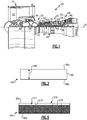
- FIG. 1 schematically illustrates a gas turbine engine 20.
- the gas turbine engine 20 is disclosed herein as a two-spool turbofan that generally incorporates a fan section 22, a compressor section 24, a combustor section 26 and a turbine section 28.
- Alternative engines might include an augmentor section (not shown) among other systems or features.
- the fan section 22 drives air along a bypass flow path while the compressor section 24 drives air along a core flow path for compression and communication into the combustor section 26 then expansion through the turbine section 28.
- FIG. 1 schematically illustrates a gas turbine engine 20.
- the gas turbine engine 20 is disclosed herein as a two-spool turbofan that generally incorporates a fan section 22, a compressor section 24, a combustor section 26 and a turbine section 28.
- Alternative engines might include an augmentor section (not shown) among other systems or features.
- the fan section 22 drives air along a bypass flow path while the compressor section 24 drives air along a core flow path for compression and communication into the combustor section 26
- the engine 20 generally includes a first spool 30 and a second spool 32 mounted for rotation about an engine central axis A relative to an engine static structure 36 via several bearing systems 38. It should be understood that various bearing systems 38 at various locations may alternatively or additionally be provided.
- the first spool 30 generally includes a first shaft 40 that interconnects a fan 42, a first compressor 44 and a first turbine 46.
- the first shaft 40 is connected to the fan 42 through a gear assembly of a fan drive gear system 48 to drive the fan 42 at a lower speed than the first spool 30.
- the second spool 32 includes a second shaft 50 that interconnects a second compressor 52 and second turbine 54.
- the first spool 30 runs at a relatively lower pressure than the second spool 32. It is to be understood that "low pressure” and “high pressure” or variations thereof as used herein are relative terms indicating that the high pressure is greater than the low pressure.
- An annular combustor 56 is arranged between the second compressor 52 and the second turbine 54.
- the first shaft 40 and the second shaft 50 are concentric and rotate via bearing systems 38 about the engine central axis A which is collinear with their longitudinal axes.
- the core airflow is compressed by the first compressor 44 then the second compressor 52, mixed and burned with fuel in the annular combustor 56, then expanded over the second turbine 54 and first turbine 46.
- the first turbine 46 and the second turbine 54 rotationally drive, respectively, the first spool 30 and the second spool 32 in response to the expansion.
- the engine 20 is a high-bypass geared aircraft engine that has a bypass ratio that is greater than about six (6), with an example embodiment being greater than ten (10), the gear assembly of the fan drive gear system 48 is an epicyclic gear train, such as a planetary gear system or other gear system, with a gear reduction ratio of greater than about 2.3:1 and the first turbine 46 has a pressure ratio that is greater than about 5.
- the first turbine 46 pressure ratio is pressure measured prior to inlet of first turbine 46 as related to the pressure at the outlet of the first turbine 46 prior to an exhaust nozzle.
- the first turbine 46 has a maximum rotor diameter and the fan 42 has a fan diameter such that a ratio of the maximum rotor diameter divided by the fan diameter is less than 0.6. It should be understood, however, that the above parameters are only exemplary.
- the fan section 22 of the engine 20 is designed for a particular flight condition -- typically cruise at about 0.8 Mach and about 10,668m (35,000 feet). The flight condition of 0.8 Mach and 10,668m (35,000 feet), with the engine at its best fuel consumption. To make an accurate comparison of fuel consumption between engines, fuel consumption is reduced to a common denominator, which is applicable to all types and sizes of turbojets and turbofans.
- the term is thrust specific fuel consumption, or TSFC. This is an engine's fuel consumption in g/s (pounds per hour) divided by the net thrust. The result is the amount of fuel required to produce one pound of thrust.
- the TSFC unit is grams per second - kiloNewton (g/s.kN) (pounds per hour per pounds of thrust (lb/hr/lb Fn)).
- g/s.kN grams per second - kiloNewton
- lb/hr/lb Fn pounds per hour per pounds of thrust
- SFC specific fuel consumption
- Low corrected fan tip speed is the actual fan tip speed in feet per second divided by an industry standard temperature correction of [(Tram K) / (518.7 K)] 0.5 ([(Tram °R) / (518.7 °R)] 1.5 ).
- the "Low corrected fan tip speed” as disclosed herein according to one non-limiting embodiment is less than about 350.5 m/s (1150 feet per second).
- the compressor section 24 and a turbine section 28 of the engine 20 include rotatable blades 60, also known as airfoils. As can be appreciated, the specific design of the blades 60 in the compressor section 24 can differ from that of the blades 60 in the turbine section 28.
- a static structure 62 generally surrounds the blades 60.
- the static structure 62 can be a blade outer air seal system or other type of structure that generally defines a radially outer flow path wall.
- At least one abradable seal 64 is provided between the static structure 62 and the rotatable blade 60.
- two abradable seals 64 are shown, although it is to be understood that a single abradable seal 64 or additional abradable seals 64 can be used.
- the abradable seal 64 is mounted for rotation on the blade 60.
- the abradable seal 64 can be mounted on the static structure 62.
- the abradable seal 64 includes a seal body 66 that defines a seal side 66a and a non-seal side 66b.
- the seal side 66a mates with at least a portion of the static structure 62 to limit flow leakage between the blade 60 and the static structure 62 and thus enhance engine efficiency.
- the non-seal side 66b is joined to the blade 60.
- the seal body 66 includes an abradability characteristic that varies by locality.
- locality refers to positions on or in the seal body 66.
- the abradability characteristic is a physical characteristic of the seal body 66 that influences the abradability of the seal body 66. For example, different localities in or on the seal body 66 have different levels of abradability and thus the localities abrade at different rates.
- the abradability characteristic varies across the seal surface 66a. The following examples illustrate different abradability characteristics that may be employed individually or in any combination to achieve variation by locality.
- Figure 3 illustrates an example abradable seal 164 which does not fall within the scope of the invention.
- like reference numerals designate like elements where appropriate and reference numerals with the addition of one-hundred or multiples thereof designate modified elements that are understood to incorporate the same features and benefits of the corresponding elements.
- the abradable seal 164 includes a gradient 168 between the non-seal side 66b and the seal side 66a.
- the gradient 168 is a graded composition.
- the gradient 168 is a graded porosity.
- Figure 4 illustrates selected portions of an example abradable seal 264.
- the seal side 66a of the abradable seal 264 has a cellular structure 270 that includes a plurality of cells 272 that are defined between cell walls 274.
- the cell walls 274 can have a thickness of about 15 micrometers to 1 millimeter or even greater.
- the cells 272 are hexagonal, although it is to be understood that the cells can have other geometric formations, such as other rectilinear shapes or a circular shape.
- the cells 272 define a cell center-to-center spacing 276 that varies by locality across the seal surface 66a.
- Figure 5 shows a top-down view onto the seal side 66a of the abradable seal 264.
- the abradable seal 264 includes sections 264a, 264b, and 264c that differ with respect to the center-to-center spacing 276.
- each of the sections 264a, 264b and 264c differ in abradability characteristic.
- the section 264b may have a center-to-center spacing 276 that is greater than the center-to-center spacing for either of the sections 264a and 264c, which can be equivalent.
- the section 264b has a lower volume of cell walls 274 compared to sections 264a and 264c and thus would have a higher abradability.
- the cells 272 can be provided with cores 278 that fill or partially fill the cells 272.
- the cell walls 274 are made of a first material and the cores 278 are made of a second material that differs from the first material in composition.
- the cell walls 274 are made of one of the above-described metallic alloys and the second material of the cores 278 is a different metallic alloy, a ceramic material or a polymeric material to thus provide a different abradability characteristic than the cell walls 274.
- the second material can be selected to be relatively harder than the first material of a cell wall 274.
- the cores 278 can be made from a harder metallic alloy or a ceramic material, such as a ceramic oxide or a ceramic nitride.
- the ceramic oxide can include, but is not limited, alumina and/or zirconium oxide.
- the ceramic nitride can be, but is not limited to, boron nitride.
- the abradability characteristic differs by locality in or on the abradable seal 64/164/264.
- the variation in the abradability characteristic permits the abradable seal 64/164/264 to be tailored to a particular engine design. Portions of the abradable seal 64/164/264 that are to be in contact with a mating structure, such as the static structure 62, can be made more abradable while remaining portions of the abradable seal can be made less abradable to withstand the operating environment in the engine 20. Additionally or alternatively, the abradability characteristic can be tailored to produce desirable wear patterns in the abradable seal, to facilitate enhanced sealing with the blade 60.
- the abradable seal 64/164/264 also embodies a method of controlling abradability by varying the abradability characteristic of the seal body by locality.
- the features disclosed herein may be difficult to form using conventional fabrication techniques.
- one example method of fabricating the abradable seal 64/164/264 having the features disclosed herein can include an additive manufacturing process. In such a process, powdered material is fed into a machine, which may provide a vacuum, for example. The machine deposits multiple layers of powdered material on to one another. The layers are selectively joined to one another with reference to computer design data, such as computer aided design data, to form structures that relate to a particular cross-section of the abradable seal that is to be produced.
- the powdered material is selectively melted using a direct metal laser sintering process or an energy beam melting process.
- Other layers or portions of layers corresponding to negative features, such as openings or porosity, are not joined and thus remain as a powdered material.
- the unjoined powder material is later removed using blown air, for example.
- the individual layers are fed from different compositions of materials.
- a first layer that is fed into the machine may have a first composition and a second or subsequent layer may have a different composition to produce the examples disclosed herein.
Landscapes
- Engineering & Computer Science (AREA)
- General Engineering & Computer Science (AREA)
- Mechanical Engineering (AREA)
- Chemical & Material Sciences (AREA)
- Combustion & Propulsion (AREA)
- Turbine Rotor Nozzle Sealing (AREA)
- Structures Of Non-Positive Displacement Pumps (AREA)
Claims (8)
- Joint abradable (64 ; 164 ; 264) pour un moteur à turbine à gaz, comprenant :un corps de joint (66) ayant un côté étanche (66a) et un côté non étanche (66b), le corps de joint (66) incluant une caractéristique d'abradabilité qui varie en fonction de l'emplacement,dans lequel la caractéristique d'abradabilité varie à travers le côté étanche (66a), caractérisé en ce que la caractéristique d'abradabilité est une structure de cellule à géométrie non uniforme (270) comprenant :une pluralité de cellules (272) qui sont définies entre des parois de cellule (274) ; etune dimension de centre à centre de cellule (276) qui varie en fonction de l'emplacement.
- Joint abradable selon la revendication 1, dans lequel le corps de joint (66) inclut une pluralité de cellules (272) définies entre des parois de cellule (274), les parois de cellule (274) étant constituées d'une première matière, et des coeurs de cellule (278) dans les cellules (272), les coeurs de cellule (278) étant constitués d'une seconde matière qui est différente d'une première matière dans la composition.
- Joint abradable selon la revendication 2, dans lequel la première matière est métallique et la seconde matière est la céramique.
- Joint abradable selon la revendication 2, dans lequel la première matière est métallique et la seconde matière est polymérique.
- Joint abradable selon la revendication 2, dans lequel la première matière est métallique et la seconde matière est un oxyde céramique.
- Joint abradable selon la revendication 2, dans lequel la première matière est métallique et la seconde matière est le nitrure de céramique.
- Moteur à turbine (20) comprenant :éventuellement, un ventilateur (22) ;une section de compresseur (24) ;une chambre de combustion (26) en communication fluidique avec la section de compresseur (24) ; etune section de turbine (28) en communication fluidique avec la chambre de combustion (26), la section de turbine (28) étant couplée pour entraîner la section de compresseur (24) et le ventilateur (22), etau moins l'une de la section de compresseur (24) et de la section de turbine (28) incluant un joint abradable (64 ; 164 ; 264) selon une quelconque revendication précédente.
- Procédé de commande de l'abradabilité d'un joint abradable (64 ; 164 ; 264) pour un moteur à turbine à gaz (20), le procédé comprenant :dans un corps de joint (66) ayant un côté étanche (66a) et un côté non étanche (66b), la variation, en fonction de l'emplacement, d'une caractéristique d'abradabilité du corps de joint (66),dans lequel la caractéristique d'abradabilité varie à travers le côté étanche (66a),caractérisé en ce que la caractéristique d'abradabilité est une structure de cellule de géométrie non uniforme (270) comprenant :une pluralité de cellules (272) qui sont définies entre des parois de cellule (274) ; etune dimension de centre à centre de cellule (276) qui varie en fonction de l'emplacement.
Priority Applications (1)
| Application Number | Priority Date | Filing Date | Title |
|---|---|---|---|
| EP19191558.6A EP3591171B1 (fr) | 2013-02-19 | 2014-01-27 | Joint abradable comprenant une caractéristique d'abradabilité variant selon la localisation |
Applications Claiming Priority (2)
| Application Number | Priority Date | Filing Date | Title |
|---|---|---|---|
| US201361766403P | 2013-02-19 | 2013-02-19 | |
| PCT/US2014/013133 WO2014130211A1 (fr) | 2013-02-19 | 2014-01-27 | Joint abradable comprenant une caractéristique d'abradabilité qui varie en fonction de l'emplacement |
Related Child Applications (1)
| Application Number | Title | Priority Date | Filing Date |
|---|---|---|---|
| EP19191558.6A Division EP3591171B1 (fr) | 2013-02-19 | 2014-01-27 | Joint abradable comprenant une caractéristique d'abradabilité variant selon la localisation |
Publications (3)
| Publication Number | Publication Date |
|---|---|
| EP2959115A1 EP2959115A1 (fr) | 2015-12-30 |
| EP2959115A4 EP2959115A4 (fr) | 2016-11-09 |
| EP2959115B1 true EP2959115B1 (fr) | 2019-08-21 |
Family
ID=51391698
Family Applications (2)
| Application Number | Title | Priority Date | Filing Date |
|---|---|---|---|
| EP19191558.6A Active EP3591171B1 (fr) | 2013-02-19 | 2014-01-27 | Joint abradable comprenant une caractéristique d'abradabilité variant selon la localisation |
| EP14753931.6A Active EP2959115B1 (fr) | 2013-02-19 | 2014-01-27 | Joint abradable comprenant une caractéristique d'abradabilité qui varie en fonction de l'emplacement |
Family Applications Before (1)
| Application Number | Title | Priority Date | Filing Date |
|---|---|---|---|
| EP19191558.6A Active EP3591171B1 (fr) | 2013-02-19 | 2014-01-27 | Joint abradable comprenant une caractéristique d'abradabilité variant selon la localisation |
Country Status (3)
| Country | Link |
|---|---|
| US (1) | US20160003083A1 (fr) |
| EP (2) | EP3591171B1 (fr) |
| WO (1) | WO2014130211A1 (fr) |
Families Citing this family (12)
| Publication number | Priority date | Publication date | Assignee | Title |
|---|---|---|---|---|
| US10030532B2 (en) * | 2015-04-22 | 2018-07-24 | United Technologies Corporation | Abradable seal with thermally conductive microspheres |
| US9644489B1 (en) * | 2015-12-16 | 2017-05-09 | Siemens Energy, Inc. | Additive manufacturing of abradable mesh structure on ring segment surface |
| US11225878B1 (en) | 2016-12-21 | 2022-01-18 | Technetics Group Llc | Abradable composite material and method of making the same |
| US10369630B2 (en) * | 2017-02-24 | 2019-08-06 | General Electric Company | Polyhedral-sealed article and method for forming polyhedral-sealed article |
| DE102017204588B4 (de) * | 2017-03-20 | 2019-03-28 | KSB SE & Co. KGaA | Verbundbauteil |
| DE102017211316A1 (de) | 2017-07-04 | 2019-01-10 | MTU Aero Engines AG | Turbomaschinen-Dichtring |
| US11346232B2 (en) | 2018-04-23 | 2022-05-31 | Rolls-Royce Corporation | Turbine blade with abradable tip |
| US11286807B2 (en) | 2018-09-28 | 2022-03-29 | General Electric Company | Metallic compliant tip fan blade |
| US10920607B2 (en) | 2018-09-28 | 2021-02-16 | General Electric Company | Metallic compliant tip fan blade |
| CN111570793A (zh) * | 2020-05-15 | 2020-08-25 | 中国航发北京航空材料研究院 | 多孔结构变密度梯度金属材料的激光选区熔化制备方法 |
| CN111451505A (zh) * | 2020-05-15 | 2020-07-28 | 中国航发北京航空材料研究院 | 一种金属点阵结构变密度梯度材料的激光选区熔化制备工艺 |
| US20220112815A1 (en) * | 2020-10-13 | 2022-04-14 | General Electric Company | Abradable seal structure for gas turbine formed using binder jetting |
Citations (1)
| Publication number | Priority date | Publication date | Assignee | Title |
|---|---|---|---|---|
| EP2317079A2 (fr) * | 2009-10-30 | 2011-05-04 | Alstom Technology Ltd | Système de revêtement abradable |
Family Cites Families (14)
| Publication number | Priority date | Publication date | Assignee | Title |
|---|---|---|---|---|
| US4022481A (en) * | 1973-02-23 | 1977-05-10 | International Harvester Company | Compliant structural members |
| US4639388A (en) * | 1985-02-12 | 1987-01-27 | Chromalloy American Corporation | Ceramic-metal composites |
| US4867639A (en) * | 1987-09-22 | 1989-09-19 | Allied-Signal Inc. | Abradable shroud coating |
| DE10337094A1 (de) * | 2003-08-12 | 2005-03-03 | Mtu Aero Engines Gmbh | Einlaufbelag für Gasturbinen sowie Verfahren zur Herstellung desselben |
| US7473072B2 (en) * | 2005-02-01 | 2009-01-06 | Honeywell International Inc. | Turbine blade tip and shroud clearance control coating system |
| US7686570B2 (en) * | 2006-08-01 | 2010-03-30 | Siemens Energy, Inc. | Abradable coating system |
| US20080274336A1 (en) * | 2006-12-01 | 2008-11-06 | Siemens Power Generation, Inc. | High temperature insulation with enhanced abradability |
| US20080260523A1 (en) * | 2007-04-18 | 2008-10-23 | Ioannis Alvanos | Gas turbine engine with integrated abradable seal |
| US20090072488A1 (en) * | 2007-09-18 | 2009-03-19 | Honeywell International, Inc. | Labyrinth seals and methods of manufacture |
| US8309197B2 (en) * | 2008-12-17 | 2012-11-13 | Teledyne Scientific & Imaging, Llc | Integral abradable seals |
| US20110164961A1 (en) | 2009-07-14 | 2011-07-07 | Thomas Alan Taylor | Coating system for clearance control in rotating machinery |
| WO2011100311A1 (fr) * | 2010-02-09 | 2011-08-18 | Rolls-Royce Corporation | Revêtements de céramique pouvant être abrasés et systèmes de revêtement |
| US9133712B2 (en) * | 2012-04-24 | 2015-09-15 | United Technologies Corporation | Blade having porous, abradable element |
| US9511436B2 (en) * | 2013-11-08 | 2016-12-06 | General Electric Company | Composite composition for turbine blade tips, related articles, and methods |
-
2014
- 2014-01-27 WO PCT/US2014/013133 patent/WO2014130211A1/fr active Application Filing
- 2014-01-27 US US14/767,314 patent/US20160003083A1/en not_active Abandoned
- 2014-01-27 EP EP19191558.6A patent/EP3591171B1/fr active Active
- 2014-01-27 EP EP14753931.6A patent/EP2959115B1/fr active Active
Patent Citations (1)
| Publication number | Priority date | Publication date | Assignee | Title |
|---|---|---|---|---|
| EP2317079A2 (fr) * | 2009-10-30 | 2011-05-04 | Alstom Technology Ltd | Système de revêtement abradable |
Also Published As
| Publication number | Publication date |
|---|---|
| US20160003083A1 (en) | 2016-01-07 |
| EP2959115A4 (fr) | 2016-11-09 |
| EP2959115A1 (fr) | 2015-12-30 |
| WO2014130211A1 (fr) | 2014-08-28 |
| EP3591171B1 (fr) | 2021-04-07 |
| EP3591171A1 (fr) | 2020-01-08 |
Similar Documents
| Publication | Publication Date | Title |
|---|---|---|
| EP2959115B1 (fr) | Joint abradable comprenant une caractéristique d'abradabilité qui varie en fonction de l'emplacement | |
| EP3617451B1 (fr) | Aube à élément poreux abradable et procédé d'usinage associé | |
| EP3056674B1 (fr) | Article possédant un passage de refroidissement avec profil ondulé | |
| EP2942488B1 (fr) | Aube rotorique de moteur à turbine à gaz, moteur à turbine à gaz et procédé de refroidissement d'une aube rotorique de moteur à turbine à gaz | |
| EP3323984B1 (fr) | Profil aérodynamique comportant une section de revêtement segmentée géométriquement | |
| EP3351729B1 (fr) | Composant de moteur à turbine à gaz et moteur à turbine à gaz associé | |
| EP3133251B1 (fr) | Composant d'étanchéité à l'air extérieur de lame avec un coefficient de dilatation thermique variable | |
| US9752442B2 (en) | Airfoil with variable profile responsive to thermal conditions | |
| US20190316474A1 (en) | Cupped contour for gas turbine engine blade assembly | |
| US20160001354A1 (en) | Gas turbine engine component manufacturing method and core for making same | |
| US20180135441A1 (en) | Airfoil with geometrically segmented coating section | |
| US11148190B2 (en) | Rib bumper system | |
| EP3323996B1 (fr) | Composant de moteur à turbine avec section de revêtement segmenté géométriquement et passage de refroidissement | |
| EP3196419A1 (fr) | Joint d'air extérieure d'aube ayant une couche superficielle avec des poches | |
| EP3693563B1 (fr) | Motif de divot pour revêtement de barrière thermique | |
| US11143042B2 (en) | System and method for applying a metallic coating | |
| EP2890878B1 (fr) | Joint d'étanchéité à l'air externe d'aube | |
| EP2971548B1 (fr) | Joint à léchette pour un moteur à turbine à gaz, moteur à turbine à gaz et procédé d'étanchéification d'une zone haute pression par rapport à une zone basse pression d'un moteur à turbine à gaz | |
| EP3176378B1 (fr) | Revêtement barrière thermique à pouvoir d'adhésion amélioré | |
| EP3556998B1 (fr) | Joint d'air ayant une partie de trajectoire de gaz comportant un revêtement segmenté géométriquement | |
| EP3660275A1 (fr) | Revêtement abradable pour etancheite boas rainurés | |
| EP3156613B1 (fr) | Joint externe d'aube |
Legal Events
| Date | Code | Title | Description |
|---|---|---|---|
| PUAI | Public reference made under article 153(3) epc to a published international application that has entered the european phase |
Free format text: ORIGINAL CODE: 0009012 |
|
| 17P | Request for examination filed |
Effective date: 20150910 |
|
| AK | Designated contracting states |
Kind code of ref document: A1 Designated state(s): AL AT BE BG CH CY CZ DE DK EE ES FI FR GB GR HR HU IE IS IT LI LT LU LV MC MK MT NL NO PL PT RO RS SE SI SK SM TR |
|
| AX | Request for extension of the european patent |
Extension state: BA ME |
|
| DAX | Request for extension of the european patent (deleted) | ||
| RAP1 | Party data changed (applicant data changed or rights of an application transferred) |
Owner name: UNITED TECHNOLOGIES CORPORATION |
|
| A4 | Supplementary search report drawn up and despatched |
Effective date: 20161011 |
|
| RIC1 | Information provided on ipc code assigned before grant |
Ipc: F01D 11/12 20060101AFI20161005BHEP Ipc: F16J 15/44 20060101ALI20161005BHEP |
|
| STAA | Information on the status of an ep patent application or granted ep patent |
Free format text: STATUS: EXAMINATION IS IN PROGRESS |
|
| 17Q | First examination report despatched |
Effective date: 20180309 |
|
| GRAP | Despatch of communication of intention to grant a patent |
Free format text: ORIGINAL CODE: EPIDOSNIGR1 |
|
| STAA | Information on the status of an ep patent application or granted ep patent |
Free format text: STATUS: GRANT OF PATENT IS INTENDED |
|
| INTG | Intention to grant announced |
Effective date: 20190226 |
|
| GRAS | Grant fee paid |
Free format text: ORIGINAL CODE: EPIDOSNIGR3 |
|
| GRAA | (expected) grant |
Free format text: ORIGINAL CODE: 0009210 |
|
| STAA | Information on the status of an ep patent application or granted ep patent |
Free format text: STATUS: THE PATENT HAS BEEN GRANTED |
|
| AK | Designated contracting states |
Kind code of ref document: B1 Designated state(s): AL AT BE BG CH CY CZ DE DK EE ES FI FR GB GR HR HU IE IS IT LI LT LU LV MC MK MT NL NO PL PT RO RS SE SI SK SM TR |
|
| REG | Reference to a national code |
Ref country code: GB Ref legal event code: FG4D |
|
| REG | Reference to a national code |
Ref country code: CH Ref legal event code: EP |
|
| REG | Reference to a national code |
Ref country code: DE Ref legal event code: R096 Ref document number: 602014052170 Country of ref document: DE |
|
| REG | Reference to a national code |
Ref country code: AT Ref legal event code: REF Ref document number: 1169986 Country of ref document: AT Kind code of ref document: T Effective date: 20190915 |
|
| REG | Reference to a national code |
Ref country code: IE Ref legal event code: FG4D |
|
| REG | Reference to a national code |
Ref country code: LT Ref legal event code: MG4D |
|
| REG | Reference to a national code |
Ref country code: NL Ref legal event code: MP Effective date: 20190821 |
|
| PG25 | Lapsed in a contracting state [announced via postgrant information from national office to epo] |
Ref country code: FI Free format text: LAPSE BECAUSE OF FAILURE TO SUBMIT A TRANSLATION OF THE DESCRIPTION OR TO PAY THE FEE WITHIN THE PRESCRIBED TIME-LIMIT Effective date: 20190821 Ref country code: LT Free format text: LAPSE BECAUSE OF FAILURE TO SUBMIT A TRANSLATION OF THE DESCRIPTION OR TO PAY THE FEE WITHIN THE PRESCRIBED TIME-LIMIT Effective date: 20190821 Ref country code: NL Free format text: LAPSE BECAUSE OF FAILURE TO SUBMIT A TRANSLATION OF THE DESCRIPTION OR TO PAY THE FEE WITHIN THE PRESCRIBED TIME-LIMIT Effective date: 20190821 Ref country code: BG Free format text: LAPSE BECAUSE OF FAILURE TO SUBMIT A TRANSLATION OF THE DESCRIPTION OR TO PAY THE FEE WITHIN THE PRESCRIBED TIME-LIMIT Effective date: 20191121 Ref country code: NO Free format text: LAPSE BECAUSE OF FAILURE TO SUBMIT A TRANSLATION OF THE DESCRIPTION OR TO PAY THE FEE WITHIN THE PRESCRIBED TIME-LIMIT Effective date: 20191121 Ref country code: PT Free format text: LAPSE BECAUSE OF FAILURE TO SUBMIT A TRANSLATION OF THE DESCRIPTION OR TO PAY THE FEE WITHIN THE PRESCRIBED TIME-LIMIT Effective date: 20191223 Ref country code: HR Free format text: LAPSE BECAUSE OF FAILURE TO SUBMIT A TRANSLATION OF THE DESCRIPTION OR TO PAY THE FEE WITHIN THE PRESCRIBED TIME-LIMIT Effective date: 20190821 Ref country code: SE Free format text: LAPSE BECAUSE OF FAILURE TO SUBMIT A TRANSLATION OF THE DESCRIPTION OR TO PAY THE FEE WITHIN THE PRESCRIBED TIME-LIMIT Effective date: 20190821 |
|
| PG25 | Lapsed in a contracting state [announced via postgrant information from national office to epo] |
Ref country code: IS Free format text: LAPSE BECAUSE OF FAILURE TO SUBMIT A TRANSLATION OF THE DESCRIPTION OR TO PAY THE FEE WITHIN THE PRESCRIBED TIME-LIMIT Effective date: 20191221 Ref country code: RS Free format text: LAPSE BECAUSE OF FAILURE TO SUBMIT A TRANSLATION OF THE DESCRIPTION OR TO PAY THE FEE WITHIN THE PRESCRIBED TIME-LIMIT Effective date: 20190821 Ref country code: GR Free format text: LAPSE BECAUSE OF FAILURE TO SUBMIT A TRANSLATION OF THE DESCRIPTION OR TO PAY THE FEE WITHIN THE PRESCRIBED TIME-LIMIT Effective date: 20191122 Ref country code: ES Free format text: LAPSE BECAUSE OF FAILURE TO SUBMIT A TRANSLATION OF THE DESCRIPTION OR TO PAY THE FEE WITHIN THE PRESCRIBED TIME-LIMIT Effective date: 20190821 Ref country code: LV Free format text: LAPSE BECAUSE OF FAILURE TO SUBMIT A TRANSLATION OF THE DESCRIPTION OR TO PAY THE FEE WITHIN THE PRESCRIBED TIME-LIMIT Effective date: 20190821 Ref country code: AL Free format text: LAPSE BECAUSE OF FAILURE TO SUBMIT A TRANSLATION OF THE DESCRIPTION OR TO PAY THE FEE WITHIN THE PRESCRIBED TIME-LIMIT Effective date: 20190821 |
|
| REG | Reference to a national code |
Ref country code: AT Ref legal event code: MK05 Ref document number: 1169986 Country of ref document: AT Kind code of ref document: T Effective date: 20190821 |
|
| PG25 | Lapsed in a contracting state [announced via postgrant information from national office to epo] |
Ref country code: TR Free format text: LAPSE BECAUSE OF FAILURE TO SUBMIT A TRANSLATION OF THE DESCRIPTION OR TO PAY THE FEE WITHIN THE PRESCRIBED TIME-LIMIT Effective date: 20190821 |
|
| PG25 | Lapsed in a contracting state [announced via postgrant information from national office to epo] |
Ref country code: PL Free format text: LAPSE BECAUSE OF FAILURE TO SUBMIT A TRANSLATION OF THE DESCRIPTION OR TO PAY THE FEE WITHIN THE PRESCRIBED TIME-LIMIT Effective date: 20190821 Ref country code: EE Free format text: LAPSE BECAUSE OF FAILURE TO SUBMIT A TRANSLATION OF THE DESCRIPTION OR TO PAY THE FEE WITHIN THE PRESCRIBED TIME-LIMIT Effective date: 20190821 Ref country code: IT Free format text: LAPSE BECAUSE OF FAILURE TO SUBMIT A TRANSLATION OF THE DESCRIPTION OR TO PAY THE FEE WITHIN THE PRESCRIBED TIME-LIMIT Effective date: 20190821 Ref country code: AT Free format text: LAPSE BECAUSE OF FAILURE TO SUBMIT A TRANSLATION OF THE DESCRIPTION OR TO PAY THE FEE WITHIN THE PRESCRIBED TIME-LIMIT Effective date: 20190821 Ref country code: DK Free format text: LAPSE BECAUSE OF FAILURE TO SUBMIT A TRANSLATION OF THE DESCRIPTION OR TO PAY THE FEE WITHIN THE PRESCRIBED TIME-LIMIT Effective date: 20190821 Ref country code: RO Free format text: LAPSE BECAUSE OF FAILURE TO SUBMIT A TRANSLATION OF THE DESCRIPTION OR TO PAY THE FEE WITHIN THE PRESCRIBED TIME-LIMIT Effective date: 20190821 |
|
| PG25 | Lapsed in a contracting state [announced via postgrant information from national office to epo] |
Ref country code: SK Free format text: LAPSE BECAUSE OF FAILURE TO SUBMIT A TRANSLATION OF THE DESCRIPTION OR TO PAY THE FEE WITHIN THE PRESCRIBED TIME-LIMIT Effective date: 20190821 Ref country code: CZ Free format text: LAPSE BECAUSE OF FAILURE TO SUBMIT A TRANSLATION OF THE DESCRIPTION OR TO PAY THE FEE WITHIN THE PRESCRIBED TIME-LIMIT Effective date: 20190821 Ref country code: IS Free format text: LAPSE BECAUSE OF FAILURE TO SUBMIT A TRANSLATION OF THE DESCRIPTION OR TO PAY THE FEE WITHIN THE PRESCRIBED TIME-LIMIT Effective date: 20200224 Ref country code: SM Free format text: LAPSE BECAUSE OF FAILURE TO SUBMIT A TRANSLATION OF THE DESCRIPTION OR TO PAY THE FEE WITHIN THE PRESCRIBED TIME-LIMIT Effective date: 20190821 |
|
| REG | Reference to a national code |
Ref country code: DE Ref legal event code: R097 Ref document number: 602014052170 Country of ref document: DE |
|
| PLBE | No opposition filed within time limit |
Free format text: ORIGINAL CODE: 0009261 |
|
| STAA | Information on the status of an ep patent application or granted ep patent |
Free format text: STATUS: NO OPPOSITION FILED WITHIN TIME LIMIT |
|
| PG2D | Information on lapse in contracting state deleted |
Ref country code: IS |
|
| 26N | No opposition filed |
Effective date: 20200603 |
|
| PG25 | Lapsed in a contracting state [announced via postgrant information from national office to epo] |
Ref country code: SI Free format text: LAPSE BECAUSE OF FAILURE TO SUBMIT A TRANSLATION OF THE DESCRIPTION OR TO PAY THE FEE WITHIN THE PRESCRIBED TIME-LIMIT Effective date: 20190821 Ref country code: MC Free format text: LAPSE BECAUSE OF FAILURE TO SUBMIT A TRANSLATION OF THE DESCRIPTION OR TO PAY THE FEE WITHIN THE PRESCRIBED TIME-LIMIT Effective date: 20190821 |
|
| REG | Reference to a national code |
Ref country code: CH Ref legal event code: PL |
|
| REG | Reference to a national code |
Ref country code: BE Ref legal event code: MM Effective date: 20200131 |
|
| PG25 | Lapsed in a contracting state [announced via postgrant information from national office to epo] |
Ref country code: LU Free format text: LAPSE BECAUSE OF NON-PAYMENT OF DUE FEES Effective date: 20200127 |
|
| PG25 | Lapsed in a contracting state [announced via postgrant information from national office to epo] |
Ref country code: BE Free format text: LAPSE BECAUSE OF NON-PAYMENT OF DUE FEES Effective date: 20200131 Ref country code: LI Free format text: LAPSE BECAUSE OF NON-PAYMENT OF DUE FEES Effective date: 20200131 Ref country code: CH Free format text: LAPSE BECAUSE OF NON-PAYMENT OF DUE FEES Effective date: 20200131 |
|
| PG25 | Lapsed in a contracting state [announced via postgrant information from national office to epo] |
Ref country code: IE Free format text: LAPSE BECAUSE OF NON-PAYMENT OF DUE FEES Effective date: 20200127 |
|
| PG25 | Lapsed in a contracting state [announced via postgrant information from national office to epo] |
Ref country code: MT Free format text: LAPSE BECAUSE OF FAILURE TO SUBMIT A TRANSLATION OF THE DESCRIPTION OR TO PAY THE FEE WITHIN THE PRESCRIBED TIME-LIMIT Effective date: 20190821 Ref country code: CY Free format text: LAPSE BECAUSE OF FAILURE TO SUBMIT A TRANSLATION OF THE DESCRIPTION OR TO PAY THE FEE WITHIN THE PRESCRIBED TIME-LIMIT Effective date: 20190821 |
|
| PG25 | Lapsed in a contracting state [announced via postgrant information from national office to epo] |
Ref country code: MK Free format text: LAPSE BECAUSE OF FAILURE TO SUBMIT A TRANSLATION OF THE DESCRIPTION OR TO PAY THE FEE WITHIN THE PRESCRIBED TIME-LIMIT Effective date: 20190821 |
|
| REG | Reference to a national code |
Ref country code: DE Ref legal event code: R081 Ref document number: 602014052170 Country of ref document: DE Owner name: RAYTHEON TECHNOLOGIES CORPORATION (N.D.GES.D.S, US Free format text: FORMER OWNER: UNITED TECHNOLOGIES CORPORATION, FARMINGTON, CONN., US |
|
| P01 | Opt-out of the competence of the unified patent court (upc) registered |
Effective date: 20230520 |
|
| PGFP | Annual fee paid to national office [announced via postgrant information from national office to epo] |
Ref country code: GB Payment date: 20231219 Year of fee payment: 11 |
|
| PGFP | Annual fee paid to national office [announced via postgrant information from national office to epo] |
Ref country code: FR Payment date: 20231219 Year of fee payment: 11 |
|
| PGFP | Annual fee paid to national office [announced via postgrant information from national office to epo] |
Ref country code: DE Payment date: 20231219 Year of fee payment: 11 |