EP2959093B1 - Apparatus and method for separating and weighing cuttings received from a wellbore while drilling - Google Patents
Apparatus and method for separating and weighing cuttings received from a wellbore while drilling Download PDFInfo
- Publication number
- EP2959093B1 EP2959093B1 EP14754040.5A EP14754040A EP2959093B1 EP 2959093 B1 EP2959093 B1 EP 2959093B1 EP 14754040 A EP14754040 A EP 14754040A EP 2959093 B1 EP2959093 B1 EP 2959093B1
- Authority
- EP
- European Patent Office
- Prior art keywords
- cuttings
- movable member
- weight
- received
- wellbore
- Prior art date
- Legal status (The legal status is an assumption and is not a legal conclusion. Google has not performed a legal analysis and makes no representation as to the accuracy of the status listed.)
- Active
Links
Images


Classifications
-
- E—FIXED CONSTRUCTIONS
- E21—EARTH OR ROCK DRILLING; MINING
- E21B—EARTH OR ROCK DRILLING; OBTAINING OIL, GAS, WATER, SOLUBLE OR MELTABLE MATERIALS OR A SLURRY OF MINERALS FROM WELLS
- E21B21/00—Methods or apparatus for flushing boreholes, e.g. by use of exhaust air from motor
- E21B21/01—Arrangements for handling drilling fluids or cuttings outside the borehole, e.g. mud boxes
-
- E—FIXED CONSTRUCTIONS
- E21—EARTH OR ROCK DRILLING; MINING
- E21B—EARTH OR ROCK DRILLING; OBTAINING OIL, GAS, WATER, SOLUBLE OR MELTABLE MATERIALS OR A SLURRY OF MINERALS FROM WELLS
- E21B49/00—Testing the nature of borehole walls; Formation testing; Methods or apparatus for obtaining samples of soil or well fluids, specially adapted to earth drilling or wells
- E21B49/005—Testing the nature of borehole walls or the formation by using drilling mud or cutting data
Definitions
- the present disclosure relates to drilling systems that include a system for separating cuttings at a well site.
- Wellbores or wells for recovery of hydrocarbons are drilled using a drill string that includes a tubular conveyed from a surface location into the wellbore.
- the drill string includes a drilling assembly (also referred to as a bottomhole assembly or "BHA”) at the bottom end of the tubular that includes a variety of tools and devices and a drill bit.
- BHA bottomhole assembly
- the drill bit is rotated by rotating the drill string and/or a motor in the drilling assembly to disintegrate rocks.
- a drilling fluid commonly referred to as the "mud” is supplied under pressure from the surface to the drill string.
- the drilling fluid discharges at the bottom of the drill bit and returns to the surface via a spacing between the wellbore and drill string, referred to as the "annulus.”
- the returning fluid carries the disintegrated rocks (referred to as the "cuttings") to the surface.
- the cuttings are separated from the returning drilling fluid and are typically either dumped into vessels, which are transported from the well site or dumped onto seabed with no weight or volumetric measurements.
- the weight of the cuttings is typically determined by weighing the vessels and the volume of the cuttings is determined from the volume of the vessels occupied by the cuttings.
- the weight and volume provides information relating to quality of the wellbore being drilled and certain characteristics of the rock formation drilled, such as density and the composition of the formation.
- WO 93/05366 A2 describes an apparatus for determining the variations in weight of detritus in drilling fluid discharged during a well drilling operation.
- the apparatus utilizes a shale shaker to remove the detritus, a plurality of receptacles, each of which supported on a device for sequential movement to and through a detritus receiving position, a measuring device in operative connection to measure the weight of detritus collected in a selected receptacle to produce an output in response to the weight of detritus measured, and a lock device to maintain a selected receptacle in the receiving position for receipt of detritus, the lock device being releasable when the weight in the selected receptacle reaches a predetermined weight to allow the support device to move under the weight of detritus in the receptacle away from the receiving position while at the same time a receptacle moves into the receiving position.
- US 2008/250853 A1 describes a device for the quantitative analysis of debris produced during drilling.
- the device comprises a conveyor belt wound on at least two rollers, for progressive collection of the debris, at least four sensing elements placed so as to take a direct measurement of the weight force exerted on the conveyor belt for the progressive weighing of the debris collected, and means for periodical discharging of the debris wherein said means for discharging debris comprise the unit for actuation of the rollers.
- US 6 410 862 B1 teaches a device for measuring drilling debris or cuttings.
- the device comprises means of collecting spoil and means of continuously measuring the weight of spoil collected.
- the means of collecting the spoil comprise a receptacle and means of tilting the receptacle in such a way that the bucket is emptied.
- the measurement means comprise a measuring cell connected to the tilting means in order to measure a stress proportional to the weight of the spoil collected.
- US 2011/266065 A1 describes a device for the quantitative analysis of debris preferably produced while drilling, comprising: means for the progressive collection of debris; means for the progressive weighing of collected debris; means for unloading the same preferably in a discharge channel; and a support structure for the device, wherein said means for the collection of the debris comprise a collection tray which is capable of performing two types of movement: a rotation movement around an axis which allows alternate loading and unloading of debris and a backward movement which is simultaneous with the rotation movement, thereby allowing for a decisive reduction in the overall vertical dimension of the structure.
- Such systems and methods are not efficient and can take substantial time from the time the cuttings are separated and weighed.
- the disclosure herein provides apparatus and methods for determining the weight of the cuttings as they are separated.
- FIG. 1 shows an exemplary drilling system 100 that includes a drill string 110 that comprises a drilling assembly or bottomhole assembly (BHA) 120 attached to a bottom end of a drilling tubular 112 (such as a drill pipe).
- BHA bottomhole assembly
- a drill bit 124 attached to the bottom of the drilling assembly is used to drill a wellbore 104 in a formation 101.
- the drilling system 100 is further shown to include a conventional derrick 150 erected on a platform 152 that supports a rotary table 154 rotated by a prime mover, such as an electric motor or a top drive (not shown).
- the rotary table 154 or the top drive connected to the tubular 112 rotates the drilling tubular 112 at a desired rotational speed to drill the wellbore 104.
- the drilling tubular 112 typically includes jointed metallic pipe sections and extends downward from the rotary table 152 into the wellbore 104.
- the drill bit 124 attached to the end of the drilling assembly 120 disintegrates the geological formations to form the wellbore 104.
- the drill string 110 is coupled to a drawworks 130 that controls the weight on bit (WOB), which affects the rate of penetration.
- WOB weight on bit
- a mud pump 160 supplies, via a line 166, a suitable drilling fluid or mud 162a under pressure from a source or mud pit 162 to the drill string 110.
- the drilling fluid 162a discharges at the wellbore bottom 104a through openings in the drill bit 124.
- the drilling fluid 162a discharged at the bottom 104a collects cuttings 164 resulting from disintegration of the formation.
- the mixture 162b of drilling fluid 162a and cuttings 164 returns to the surface via an annular space 128 between the drill string 110 and the wellbore 104 and a return line 140.
- Sensors S 1 and S 2 associated with or in the line 166 provide information about the flow rate and pressure, respectively, of the fluid being supplied to the drill string 110.
- Sensors S 3 and S 4 associated with or in return line 140 provide information about the flow rate and pressure, respectively, of the returning mixture 162b.
- the returning mixture 162b is discharged into a separator 180 that separates the mixture 162b into cuttings 174 a fluid 164c.
- the fluid 162c in one aspect, may be discharged into the mud pit 162 via a line 141 or processed and then discharged into the mud pit 162.
- the cuttings 174 separated by the separator 180 may be discharged onto a moving member 184 of a receiving unit 186.
- Sensors 188 associated with the receiving unit 186 provide signals relating to the weight of the cuttings 174 on the moving member 184.
- the cuttings 174 from the moving member 184 may be discharged into vessels 189 and transported for further disposal.
- a controller such as a computer-based system 190 may be utilized to process the signals from the sensors 188 to determine the weight of the cuttings 174 being received on the moving member while drilling.
- the volume of the cuttings 174 being received may be determined from the weight and estimated density of the cuttings 174 or from the volume of the vessels 189.
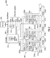
- FIG. 2 shows a system 200 for determining weight and volume of cuttings received from a wellbore during drilling of such wellbore, according to one embodiment of the disclosure.
- the system 200 shows a number of cutting weighing units 210a, 210b through 210n. Each such weighing unit is shown to include a movable member and one or more load cells.
- weighing unit 210a includes a movable member 212a and one or more load cells 214a
- weighing unit 210b includes a movable member 212b and load cells 214b
- weighing unit 210n includes a movable member 212n and load cells 214n.
- the movable member may be any suitable member that is configured to receive the cuttings thereon and discharge such received cuttings into a vessel.
- the movable member may be a belt disposed on rollers, where the belt has a flat surface for receiving the cuttings and a motor that rotates or rolls the belt around the rollers.
- the system 200 is shown to include cutting separators 220a, 220b through 220n, wherein separator 220a discharges cuttings 222a onto the movable member 212a of weighing unit 210a, separator 220b discharges cuttings 222b on movable member 212b of weighing unit 210b and separator 220n discharges cuttings 222n onto the movable member 212n of weighing unit 210n.
- the drilling fluid separated by separators 220a, 220b through 220n is supplied to the drilling fluid source via fluid lines 226a, 226b through 226n respectively.
- a motor 234a drives a mechanism to roll the movable member drives, motor 230b rolls movable member 212b and motor 230n rolls movable member 212n.
- the cuttings 222a from the movable member 212a, cuttings 222b from movable member 212b and cuttings 222n from movable member 212n are discharged into vessels (not shown) via conveying members 216a, 216b through 216n, respectively, for further processing.
- a controller or control unit 240 receives signals from each of the load sensors 214a, 214b through 214n via communication lines 232a, 232b through 232n, respectively, processes such signals using the speed of the moving members, algorithms and instructions provided to the controller 240 and determines the weight of the cuttings on each movable member.
- the controller also may determine the volume of the cuttings received by each weighing unit from the determined weight and the density of the cuttings.
- the controller 240 is a computer-based system that has an associated input/output unit 242 for use by field personnel to input instructions to the controller 240.
- the controller may include desired visual indicators (such as lights and alarms relating to various operations of the system 200) collectively denoted by numeral 244.
- the information from the controller 240 may be communicated via a communication link (wired, optical, wireless, etc.) to a remote unit 250 for operators to exchange information with the controller 240 and/or provide instructions thereto.
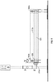
- FIG. 3 shows a front view 300 of a weighing unit, such as unit 210a
- FIG. 4 shows a top view 400 of the weighing unit 210a
- the movable member 212a may be mounted on adjustable mounting members 320a and 320b, such as adjustable columns. Cuttings from a separator are received on the top flat portion 412a.
- the variable speed motor 230a rotates the movable member 212a, which cases the cuttings received on the top surface 412a to roll off the side 312a of the movable member 212a.
- a suitable translational and rotational positioning and locking mechanism 340 may be provided to position and lock the movable member below the separator.
- the vertical position of the movable member may be adjusted and locked by a position locking device 346.
- a tilt and secure device or structure 347 allows an operator to tilt the movable member 212a, thereby providing access to performing maintenance on various components associated with the movable member 212a.
- a junction box 350 that includes an electrical junction box and selected control buttons for the operator to control various functions of the weighing unit 210a may be provided at any suitable location, including a suitable location on the mounting member 320a.
- FIG. 5 shows a cross-section of the movable member 212a taken along line B shown in FIG. 4 .
- the motor 230a rotates drive pulley 520 about bearings 530, which causes the belt to roll about the pulley.
- One or more load cells such as load cells 540a, 540b, etc. may be provided at suitable locations to provide information about the weight on the movable member 212a.
- cuttings received from a wellbore and separated by a separator at the well site are discharged onto a member moving at a selected speed.
- One or more sensors provide information about the weight on the moving member.
- a controller at the well site/and or at a remote location using the measurements from the sensors determines the weight of the cuttings received by the moving member in real time during drilling of the wellbore. Volume of the cuttings may be determined from the determined weight and estimated density of the received cuttings. Such information may be utilized to determine the quality of the well being drilled and certain characteristics of the formation being drilled.
Landscapes
- Engineering & Computer Science (AREA)
- Life Sciences & Earth Sciences (AREA)
- Geology (AREA)
- Mining & Mineral Resources (AREA)
- Physics & Mathematics (AREA)
- Environmental & Geological Engineering (AREA)
- Fluid Mechanics (AREA)
- General Life Sciences & Earth Sciences (AREA)
- Geochemistry & Mineralogy (AREA)
- Mechanical Engineering (AREA)
- Earth Drilling (AREA)
Description
- This application claims the benefit of
U.S. Application No. 13/774786, filed on February 22, 2013 - The present disclosure relates to drilling systems that include a system for separating cuttings at a well site.
- Wellbores or wells for recovery of hydrocarbons (oil and gas) are drilled using a drill string that includes a tubular conveyed from a surface location into the wellbore. The drill string includes a drilling assembly (also referred to as a bottomhole assembly or "BHA") at the bottom end of the tubular that includes a variety of tools and devices and a drill bit. The drill bit is rotated by rotating the drill string and/or a motor in the drilling assembly to disintegrate rocks. A drilling fluid, commonly referred to as the "mud" is supplied under pressure from the surface to the drill string. The drilling fluid discharges at the bottom of the drill bit and returns to the surface via a spacing between the wellbore and drill string, referred to as the "annulus." The returning fluid carries the disintegrated rocks (referred to as the "cuttings") to the surface. The cuttings are separated from the returning drilling fluid and are typically either dumped into vessels, which are transported from the well site or dumped onto seabed with no weight or volumetric measurements. The weight of the cuttings is typically determined by weighing the vessels and the volume of the cuttings is determined from the volume of the vessels occupied by the cuttings. The weight and volume provides information relating to quality of the wellbore being drilled and certain characteristics of the rock formation drilled, such as density and the composition of the formation.
-
WO 93/05366 A2 -
US 2008/250853 A1 describes a device for the quantitative analysis of debris produced during drilling. The device comprises a conveyor belt wound on at least two rollers, for progressive collection of the debris, at least four sensing elements placed so as to take a direct measurement of the weight force exerted on the conveyor belt for the progressive weighing of the debris collected, and means for periodical discharging of the debris wherein said means for discharging debris comprise the unit for actuation of the rollers. -
US 6 410 862 B1 teaches a device for measuring drilling debris or cuttings. The device comprises means of collecting spoil and means of continuously measuring the weight of spoil collected. The means of collecting the spoil comprise a receptacle and means of tilting the receptacle in such a way that the bucket is emptied. The measurement means comprise a measuring cell connected to the tilting means in order to measure a stress proportional to the weight of the spoil collected. -
US 2011/266065 A1 describes a device for the quantitative analysis of debris preferably produced while drilling, comprising: means for the progressive collection of debris; means for the progressive weighing of collected debris; means for unloading the same preferably in a discharge channel; and a support structure for the device, wherein said means for the collection of the debris comprise a collection tray which is capable of performing two types of movement: a rotation movement around an axis which allows alternate loading and unloading of debris and a backward movement which is simultaneous with the rotation movement, thereby allowing for a decisive reduction in the overall vertical dimension of the structure. - Such systems and methods are not efficient and can take substantial time from the time the cuttings are separated and weighed. The disclosure herein provides apparatus and methods for determining the weight of the cuttings as they are separated.
- Disclosed is a system for drilling a wellbore as set forth in
independent claim 1. - Also disclosed is a method of determining an amount of cuttings received in a fluid from a wellbore as set forth in independent claim 8.
- Examples of certain features of the apparatus and method disclosed herein are summarized rather broadly in order that the detailed description thereof that follows may be better understood. There are, of course, additional features of the apparatus and method disclosed hereinafter that will form the subject of the claims.
- For detailed understanding of the present disclosure, references should be made to the following detailed description of the exemplary embodiment, taken in conjunction with the accompanying drawings, in which like elements have been given like numerals and wherein:
-
FIG. 1 is a schematic diagram of an exemplary drilling system that includes a drill string having a drilling assembly attached to its bottom end that includes a steering unit according to one embodiment of the disclosure; -
FIG. 2 shows a system for determining weight and volume of cuttings received from a wellbore during drilling of such wellbore, according to one embodiment of the disclosure; -
FIG. 3 shows a front view of a weighing unit shown inFIG. 2 ; -
FIG. 4 shows a top view of the weighing unit shown inFIG. 2 ; and -
FIG. 5 shows a cross-section of the movable member taken along line B shown inFIG. 4 . -
FIG. 1 shows anexemplary drilling system 100 that includes adrill string 110 that comprises a drilling assembly or bottomhole assembly (BHA) 120 attached to a bottom end of a drilling tubular 112 (such as a drill pipe). Adrill bit 124 attached to the bottom of the drilling assembly is used to drill awellbore 104 in aformation 101. Thedrilling system 100 is further shown to include aconventional derrick 150 erected on aplatform 152 that supports a rotary table 154 rotated by a prime mover, such as an electric motor or a top drive (not shown). The rotary table 154 or the top drive connected to the tubular 112 rotates the drilling tubular 112 at a desired rotational speed to drill thewellbore 104. The drilling tubular 112 typically includes jointed metallic pipe sections and extends downward from the rotary table 152 into thewellbore 104. Thedrill bit 124 attached to the end of thedrilling assembly 120 disintegrates the geological formations to form thewellbore 104. Thedrill string 110 is coupled to adrawworks 130 that controls the weight on bit (WOB), which affects the rate of penetration. - During drilling operations, a
mud pump 160 supplies, via aline 166, a suitable drilling fluid ormud 162a under pressure from a source ormud pit 162 to thedrill string 110. Thedrilling fluid 162a discharges at thewellbore bottom 104a through openings in thedrill bit 124. Thedrilling fluid 162a discharged at thebottom 104a collectscuttings 164 resulting from disintegration of the formation. Themixture 162b ofdrilling fluid 162a andcuttings 164 returns to the surface via anannular space 128 between thedrill string 110 and thewellbore 104 and areturn line 140. Sensors S1 and S2 associated with or in theline 166 provide information about the flow rate and pressure, respectively, of the fluid being supplied to thedrill string 110. Sensors S3 and S4 associated with or inreturn line 140 provide information about the flow rate and pressure, respectively, of the returningmixture 162b. - Still referring to
FIG. 1 , the returningmixture 162b is discharged into aseparator 180 that separates themixture 162b into cuttings 174 a fluid 164c. The fluid 162c, in one aspect, may be discharged into themud pit 162 via aline 141 or processed and then discharged into themud pit 162. In one aspect, thecuttings 174 separated by theseparator 180 may be discharged onto a movingmember 184 of areceiving unit 186.Sensors 188 associated with thereceiving unit 186 provide signals relating to the weight of thecuttings 174 on the movingmember 184. Thecuttings 174 from the movingmember 184 may be discharged intovessels 189 and transported for further disposal. A controller, such as a computer-basedsystem 190 may be utilized to process the signals from thesensors 188 to determine the weight of thecuttings 174 being received on the moving member while drilling. The volume of thecuttings 174 being received may be determined from the weight and estimated density of thecuttings 174 or from the volume of thevessels 189. -
FIG. 2 shows asystem 200 for determining weight and volume of cuttings received from a wellbore during drilling of such wellbore, according to one embodiment of the disclosure. Thesystem 200 shows a number ofcutting weighing units system 200 shown,weighing unit 210a includes amovable member 212a and one ormore load cells 214a,weighing unit 210b includes a movable member 212b andload cells 214b and weighingunit 210n includes amovable member 212n andload cells 214n. The movable member may be any suitable member that is configured to receive the cuttings thereon and discharge such received cuttings into a vessel. In an aspect, the movable member may be a belt disposed on rollers, where the belt has a flat surface for receiving the cuttings and a motor that rotates or rolls the belt around the rollers. Thesystem 200 is shown to include cuttingseparators separator 220adischarges cuttings 222a onto themovable member 212a of weighingunit 210a,separator 220b discharges cuttings 222b on movable member 212b of weighingunit 210b andseparator 220n discharges cuttings 222n onto themovable member 212n of weighingunit 210n. The drilling fluid separated byseparators fluid lines 226a, 226b through 226n respectively. As the cuttings from a separator are discharged onto the movable member of a weighing unit, its associated load cells provide continuous signals corresponding to the weight on the movable member, while the movable member is moved at a selected speed. In thesystem 200, a motor 234a drives a mechanism to roll the movable member drives, motor 230b rolls movable member 212b andmotor 230n rollsmovable member 212n. Thecuttings 222a from themovable member 212a,cuttings 222b from movable member 212b andcuttings 222n frommovable member 212n are discharged into vessels (not shown) via conveyingmembers control unit 240 receives signals from each of theload sensors communication lines controller 240 and determines the weight of the cuttings on each movable member. The controller also may determine the volume of the cuttings received by each weighing unit from the determined weight and the density of the cuttings. - In one aspect, the
controller 240 is a computer-based system that has an associated input/output unit 242 for use by field personnel to input instructions to thecontroller 240. The controller may include desired visual indicators (such as lights and alarms relating to various operations of the system 200) collectively denoted bynumeral 244. The information from thecontroller 240 may be communicated via a communication link (wired, optical, wireless, etc.) to aremote unit 250 for operators to exchange information with thecontroller 240 and/or provide instructions thereto. -
FIG. 3 shows afront view 300 of a weighing unit, such asunit 210a, andFIG. 4 shows atop view 400 of the weighingunit 210a. Referring now toFIGS. 3 and 4 , themovable member 212a may be mounted onadjustable mounting members flat portion 412a. Thevariable speed motor 230a rotates themovable member 212a, which cases the cuttings received on thetop surface 412a to roll off theside 312a of themovable member 212a. In an aspect, a suitable translational and rotational positioning andlocking mechanism 340 may be provided to position and lock the movable member below the separator. The vertical position of the movable member may be adjusted and locked by aposition locking device 346. When themovable member 212a is unlocked from the positioning andlocking mechanism 340, a tilt and secure device orstructure 347 allows an operator to tilt themovable member 212a, thereby providing access to performing maintenance on various components associated with themovable member 212a. Ajunction box 350 that includes an electrical junction box and selected control buttons for the operator to control various functions of the weighingunit 210a may be provided at any suitable location, including a suitable location on the mountingmember 320a. -
FIG. 5 shows a cross-section of themovable member 212a taken along line B shown inFIG. 4 . In the particular configuration ofFIG. 5 , themotor 230a rotates drivepulley 520 aboutbearings 530, which causes the belt to roll about the pulley. One or more load cells, such asload cells movable member 212a. - Thus, in the particular embodiment of system 200 (
FIG. 2 ) cuttings received from a wellbore and separated by a separator at the well site are discharged onto a member moving at a selected speed. One or more sensors provide information about the weight on the moving member. A controller at the well site/and or at a remote location using the measurements from the sensors determines the weight of the cuttings received by the moving member in real time during drilling of the wellbore. Volume of the cuttings may be
determined from the determined weight and estimated density of the received cuttings. Such information may be utilized to determine the quality of the well being drilled and certain characteristics of the formation being drilled.
Claims (14)
- A system (100) for drilling a wellbore (104), the system (100) comprising:a drill string (110) that drills the wellbore (104) using a drilling fluid (162a, 162c) in the wellbore (104) that returns rock cuttings (164, 174, 222a, 222b, ..., 222n) therewith to a surface location;a separator (180, 220a, 220b, ..., 220n) that separates the rock cuttings (164, 174, 222a, 222b, ..., 222n) from the drilling fluid (162a, 162c) at the surface location;a weighing unit (210a, 210b, ..., 210n) for receiving the rock cuttings (164, 174, 222a, 222b, ..., 222n) from the separator (180, 220a, 220b, ..., 220n); anda controller (190, 240) for determining the weight of the cuttings (164, 174, 222a, 222b, ..., 222n) received by the weighing unit (210a, 210b, ..., 210n); the system characterized by the weighing unit (210a, 210b, ..., 210n) including:a movable member (212a, 212b, ..., 212n) having a first longitudinal side and a second longitudinal side opposite the first longitudinal side, wherein the movable member (212a, 212b, ..., 212n) substantially continuously receives cuttings (164, 174, 222a, 222b, ..., 222n) from the separator (180, 220a, 220b, ..., 220n), wherein the movable member (212a, 212b, ..., 212n) is a belt disposed on rollers;a sensor (188, 214a, 214b, ..., 214n) for providing information relating to weight of the cuttings (164, 174, 222a, 222b, ..., 222n) received by the weighing unit (210a, 210b, ..., 210n) while the movable member (212a, 212b, ..., 212n) is moving; anda motor (230a, 230b, ..., 230n) mounted at a side of the movable member (212a, 212b, ..., 212n) adjacent the first longitudinal side and that moves the movable member (212a, 212b, ..., 212n) to discharge the cuttings (164, 174, 222a, 222b, ..., 222n) from the movable member (212a, 212b, ..., 212n) at the second longitudinal side.
- The system (100) of claim 1, wherein the movable member (212a, 212b, ..., 212n) receives the cuttings (164, 174, 222a, 222b, ..., 222n) substantially continuously from an associated separator (180, 220a, 220b, ..., 220n).
- The system (100) of claim 1 or 2, wherein the movable member (212a, 212b, ..., 212n) is placed below an outlet of the associated separator (180, 220a, 220b, ..., 220n) to receive the cuttings (164, 174, 222a, 222b, ..., 222n) directly from the separator (180, 220a, 220b, ..., 220n) and discharges the received cuttings (164, 174, 222a, 222b, ..., 222n) into a vessel (189).
- The system (100) of claim 1, wherein the controller (240) controls speed of the movable member (212a, 212b, ..., 212n) in response to the determined weight of the cuttings (164, 174, 222a, 222b, ..., 222n).
- The system (100) of claim 1 or 4, wherein the controller (240) determines volume of the cuttings (164, 174, 222a, 222b, ..., 222n) received by the weighing unit (210a, 210b, ..., 210n) from the determined weight.
- The system (100) of claim 1, wherein the movable member (212a, 212b, ..., 212n) is configured to tilt to allow access to components of the movable member (212a, 212b, ..., 212n).
- The system (100) of any of claims 1-6, wherein the controller (240) determines the weight and volume of the cuttings (164, 174, 222a, 222b, ..., 222n) substantially continuously during drilling of the wellbore (104).
- A method of determining an amount of cuttings (164, 174, 222a, 222b, ..., 222n) received in a fluid (162a, 162c) from a wellbore (104), comprising:separating the cuttings (164, 174, 222a, 222b, ...,222n) from the fluid (162a, 162c);the method characterized by:substantially continuously receiving the separated cuttings (164, 174, 222a, 222b, ..., 222n) on a movable member (212a, 212b, ...,212n) of a weighing unit (210a, 210b, ..., 210n) as the cuttings (164, 174, 222a, 222b, ..., 222n) are being separated, wherein the movable member (212a, 212b, ..., 212n) is a belt disposed on rollers;using a motor mounted at a side of the movable member (212a, 212b, ...,212n) adjacent a first longitudinal side of the movable member (212a, 212b, ...,212n) to move the cuttings (164, 174, 222a, 222b, ..., 222n) to a second longitudinal side opposite the first longitudinal side;obtaining measurements of weight of the cuttings (164, 174, 222a, 222b, ..., 222n) received by the movable member (212a, 212b, ..., 212n) while the movable member (212a, 212b, ..., 212n) is moving;determining weight of the cuttings (164, 174, 222a, 222b, ..., 222n) received by the movable member (212a, 212b, ..., 212n) from the measurements of the weight; anddischarging the cuttings (164, 174, 222a, 222b, ..., 222n) from the movable member (212a, 212b, ..., 212n) at the second longitudinal side of the movable member (212a, 212b, ..., 212n).
- The method of claim 8 further characterized by: controlling speed of the movable member (212a, 212b, ..., 212n) in response to the determined weight of the cuttings (164, 174, 222a, 222b, ..., 222n).
- The method of claim 8 or 9 further characterized by: using a controller (240) to determine the weight of the cuttings (164, 174, 222a, 222b, ..., 222n) using the measurements of the weight of the cuttings (164, 174, 222a, 222b, ..., 222n) and a speed of the movable member (212a, 212b, ..., 212n).
- The method of any of the claims 8-10, further characterized by: rolling the belt about rollers at a substantially constant speed.
- The method of any of the claims 8-11, further characterized by: receiving the separated cuttings (164, 174, 222a, 222b, ..., 222n) directly on the movable member (212a, 212b, ..., 212n) upon separating the cuttings (164, 174, 222a, 222b, ..., 222n).
- The method of any of the claims 8-12 further characterized by: determining volume of the cuttings (164, 174, 222a, 222b, ..., 222n) received by the weighing unit (210a, 210b, ..., 210n) from the determined weight of the cuttings (164, 174, 222a, 222b, ..., 222n).
- The method of any of the claims 8-13 further characterized by: controlling speed of the movable member (212a, 212b, ..., 212n) in response to the determined weight of the cuttings (164, 174, 222a, 222b, ..., 222n).
Applications Claiming Priority (2)
| Application Number | Priority Date | Filing Date | Title |
|---|---|---|---|
| US13/774,786 US9297225B2 (en) | 2013-02-22 | 2013-02-22 | Apparatus and method for separating and weighing cuttings received from a wellbore while drilling |
| PCT/US2014/017301 WO2014130622A1 (en) | 2013-02-22 | 2014-02-20 | Apparatus and method for separating and weighing cuttings received from a wellbore while drilling |
Publications (3)
| Publication Number | Publication Date |
|---|---|
| EP2959093A1 EP2959093A1 (en) | 2015-12-30 |
| EP2959093A4 EP2959093A4 (en) | 2016-09-14 |
| EP2959093B1 true EP2959093B1 (en) | 2019-05-08 |
Family
ID=51386998
Family Applications (1)
| Application Number | Title | Priority Date | Filing Date |
|---|---|---|---|
| EP14754040.5A Active EP2959093B1 (en) | 2013-02-22 | 2014-02-20 | Apparatus and method for separating and weighing cuttings received from a wellbore while drilling |
Country Status (3)
| Country | Link |
|---|---|
| US (1) | US9297225B2 (en) |
| EP (1) | EP2959093B1 (en) |
| WO (1) | WO2014130622A1 (en) |
Families Citing this family (4)
| Publication number | Priority date | Publication date | Assignee | Title |
|---|---|---|---|---|
| US9297225B2 (en) * | 2013-02-22 | 2016-03-29 | Anders K. Nesheim | Apparatus and method for separating and weighing cuttings received from a wellbore while drilling |
| AT518021B1 (en) * | 2015-12-14 | 2018-04-15 | Think And Vision Gmbh | Apparatus and method for analyzing drilling mud |
| US20230072291A1 (en) * | 2021-09-09 | 2023-03-09 | Redpath Canada Limited | Drill Cuttings Measurement Box and System for Controlling Pilot Hole Drilling |
| WO2023080898A1 (en) * | 2021-11-05 | 2023-05-11 | Halliburton Energy Services, Inc. | Correction for cuttings lag |
Citations (1)
| Publication number | Priority date | Publication date | Assignee | Title |
|---|---|---|---|---|
| US20100059291A1 (en) * | 2008-09-08 | 2010-03-11 | Equipfix | System and method for weighing particulate material moving on a conveyor |
Family Cites Families (16)
| Publication number | Priority date | Publication date | Assignee | Title |
|---|---|---|---|---|
| US2993625A (en) * | 1960-02-11 | 1961-07-25 | Sperry Rand Corp | Continuous integrator weighing apparatus |
| US5074435A (en) * | 1990-06-01 | 1991-12-24 | Don Suverkrop, Inc. | System for controlling the feed rate of a vibrating feeder |
| AU2472992A (en) * | 1991-08-30 | 1993-04-05 | Trident Creative Technology Inc. | Mass flow meter |
| DE19536871B4 (en) | 1995-10-03 | 2004-09-30 | Maschinenfabrik Besta Gmbh & Co | Bunker discharge and feed plate conveyor with automatic weighing and dosing device for bulk goods |
| US6640912B2 (en) | 1998-01-20 | 2003-11-04 | Baker Hughes Incorporated | Cuttings injection system and method |
| FR2778428B1 (en) | 1998-05-07 | 2000-08-04 | Geoservices | DEVICE AND METHOD FOR MEASURING THE FLOW OF DRILL CUTTINGS |
| DE19829036A1 (en) | 1998-06-30 | 2000-01-05 | Pfister Gmbh | Chain conveyor |
| US6527054B1 (en) | 1999-09-14 | 2003-03-04 | Deep Vision Llc | Apparatus and method for the disposition of drilling solids during drilling of subsea oilfield wellbores |
| US6386026B1 (en) | 2000-11-13 | 2002-05-14 | Konstandinos S. Zamfes | Cuttings sample catcher and method of use |
| US6607659B2 (en) * | 2000-12-19 | 2003-08-19 | Hutchison-Hayes International, Inc. | Drilling mud reclamation system with mass flow sensors |
| ITMI20051771A1 (en) * | 2005-09-22 | 2007-03-23 | Geolog S P A | DEVICE FOR QUANTITATIVE ANALYSIS OF DEBRIS |
| US7971657B2 (en) | 2005-12-13 | 2011-07-05 | Baker Hughes Incorporated | Drill cuttings transfer system and related methods |
| US8074509B2 (en) * | 2007-02-21 | 2011-12-13 | M-I Llc | Wellbore monitor |
| IT1399910B1 (en) | 2010-04-29 | 2013-05-09 | Geolog S P A | IMPROVED DEVICE FOR QUANTITATIVE ANALYSIS OF DEPRIVES. |
| US9169089B2 (en) * | 2012-06-03 | 2015-10-27 | Conveyor Application Systems Llc | System for conveying drill cuttings |
| US9297225B2 (en) * | 2013-02-22 | 2016-03-29 | Anders K. Nesheim | Apparatus and method for separating and weighing cuttings received from a wellbore while drilling |
-
2013
- 2013-02-22 US US13/774,786 patent/US9297225B2/en active Active
-
2014
- 2014-02-20 EP EP14754040.5A patent/EP2959093B1/en active Active
- 2014-02-20 WO PCT/US2014/017301 patent/WO2014130622A1/en not_active Ceased
Patent Citations (1)
| Publication number | Priority date | Publication date | Assignee | Title |
|---|---|---|---|---|
| US20100059291A1 (en) * | 2008-09-08 | 2010-03-11 | Equipfix | System and method for weighing particulate material moving on a conveyor |
Also Published As
| Publication number | Publication date |
|---|---|
| EP2959093A1 (en) | 2015-12-30 |
| US9297225B2 (en) | 2016-03-29 |
| WO2014130622A1 (en) | 2014-08-28 |
| EP2959093A4 (en) | 2016-09-14 |
| US20140238744A1 (en) | 2014-08-28 |
Similar Documents
| Publication | Publication Date | Title |
|---|---|---|
| US7243735B2 (en) | Wellbore operations monitoring and control systems and methods | |
| US4809791A (en) | Removal of rock cuttings while drilling utilizing an automatically adjustable shaker system | |
| US11481706B2 (en) | Automatic abnormal trend detection of real time drilling data for hazard avoidance | |
| EP2802738B1 (en) | System and method for improved cuttings measurements | |
| CA2790484C (en) | Reverse circulation apparatus and methods for using same | |
| US11255180B2 (en) | Robust early kick detection using real time drilling | |
| US9134291B2 (en) | Systems, methods and devices for analyzing drilling fluid | |
| EP2932032B1 (en) | Systems and methods for real-time sag detection | |
| EP3204593B1 (en) | Device and system for use in monitoring coring operations | |
| US20110280104A1 (en) | Dual top drive systems and methods for wellbore operations | |
| US20100155061A1 (en) | Formation evaluation system and method | |
| US20180051548A1 (en) | A method of performing a reaming operation at a wellsite using reamer performance metrics | |
| WO2016099529A1 (en) | Methods and apparatuses for deriving wellbore fluid sag from thermal conductivity measurements | |
| US9297225B2 (en) | Apparatus and method for separating and weighing cuttings received from a wellbore while drilling | |
| US11753925B2 (en) | Apparatus and related methods to determine hole cleaning, well bore stability and volumetric cuttings measurements | |
| CA2622249C (en) | Device for the quantitative analysis of debris | |
| Sach et al. | Repeatedly increased efficiency and success rate from a new solids-cleanout process using coiled tubing: A review of recent achievements from more than 100 operations | |
| Hanking et al. | Case History: Breitbrunn–Horizontal Foam Drilling Project in an Environmentally Sensitive Area in Bavaria, Germany | |
| CA2052565A1 (en) | Mass flow meter |
Legal Events
| Date | Code | Title | Description |
|---|---|---|---|
| PUAI | Public reference made under article 153(3) epc to a published international application that has entered the european phase |
Free format text: ORIGINAL CODE: 0009012 |
|
| 17P | Request for examination filed |
Effective date: 20150918 |
|
| AK | Designated contracting states |
Kind code of ref document: A1 Designated state(s): AL AT BE BG CH CY CZ DE DK EE ES FI FR GB GR HR HU IE IS IT LI LT LU LV MC MK MT NL NO PL PT RO RS SE SI SK SM TR |
|
| AX | Request for extension of the european patent |
Extension state: BA ME |
|
| DAX | Request for extension of the european patent (deleted) | ||
| TPAC | Observations filed by third parties |
Free format text: ORIGINAL CODE: EPIDOSNTIPA |
|
| REG | Reference to a national code |
Ref country code: DE Ref legal event code: R079 Ref document number: 602014046325 Country of ref document: DE Free format text: PREVIOUS MAIN CLASS: E21B0021080000 Ipc: E21B0021010000 |
|
| A4 | Supplementary search report drawn up and despatched |
Effective date: 20160816 |
|
| RIC1 | Information provided on ipc code assigned before grant |
Ipc: E21B 49/00 20060101ALI20160809BHEP Ipc: E21B 21/01 20060101AFI20160809BHEP |
|
| STAA | Information on the status of an ep patent application or granted ep patent |
Free format text: STATUS: EXAMINATION IS IN PROGRESS |
|
| 17Q | First examination report despatched |
Effective date: 20170711 |
|
| GRAP | Despatch of communication of intention to grant a patent |
Free format text: ORIGINAL CODE: EPIDOSNIGR1 |
|
| STAA | Information on the status of an ep patent application or granted ep patent |
Free format text: STATUS: GRANT OF PATENT IS INTENDED |
|
| INTG | Intention to grant announced |
Effective date: 20181205 |
|
| RAP1 | Party data changed (applicant data changed or rights of an application transferred) |
Owner name: BAKER HUGHES, A GE COMPANY, LLC |
|
| GRAS | Grant fee paid |
Free format text: ORIGINAL CODE: EPIDOSNIGR3 |
|
| GRAA | (expected) grant |
Free format text: ORIGINAL CODE: 0009210 |
|
| STAA | Information on the status of an ep patent application or granted ep patent |
Free format text: STATUS: THE PATENT HAS BEEN GRANTED |
|
| AK | Designated contracting states |
Kind code of ref document: B1 Designated state(s): AL AT BE BG CH CY CZ DE DK EE ES FI FR GB GR HR HU IE IS IT LI LT LU LV MC MK MT NL NO PL PT RO RS SE SI SK SM TR |
|
| REG | Reference to a national code |
Ref country code: GB Ref legal event code: FG4D |
|
| REG | Reference to a national code |
Ref country code: CH Ref legal event code: EP Ref country code: AT Ref legal event code: REF Ref document number: 1130391 Country of ref document: AT Kind code of ref document: T Effective date: 20190515 |
|
| REG | Reference to a national code |
Ref country code: DE Ref legal event code: R096 Ref document number: 602014046325 Country of ref document: DE Ref country code: IE Ref legal event code: FG4D |
|
| RAP2 | Party data changed (patent owner data changed or rights of a patent transferred) |
Owner name: BAKER HUGHES, A GE COMPANY, LLC |
|
| REG | Reference to a national code |
Ref country code: NL Ref legal event code: MP Effective date: 20190508 |
|
| REG | Reference to a national code |
Ref country code: LT Ref legal event code: MG4D |
|
| REG | Reference to a national code |
Ref country code: NO Ref legal event code: T2 Effective date: 20190508 |
|
| PG25 | Lapsed in a contracting state [announced via postgrant information from national office to epo] |
Ref country code: FI Free format text: LAPSE BECAUSE OF FAILURE TO SUBMIT A TRANSLATION OF THE DESCRIPTION OR TO PAY THE FEE WITHIN THE PRESCRIBED TIME-LIMIT Effective date: 20190508 Ref country code: LT Free format text: LAPSE BECAUSE OF FAILURE TO SUBMIT A TRANSLATION OF THE DESCRIPTION OR TO PAY THE FEE WITHIN THE PRESCRIBED TIME-LIMIT Effective date: 20190508 Ref country code: NL Free format text: LAPSE BECAUSE OF FAILURE TO SUBMIT A TRANSLATION OF THE DESCRIPTION OR TO PAY THE FEE WITHIN THE PRESCRIBED TIME-LIMIT Effective date: 20190508 Ref country code: AL Free format text: LAPSE BECAUSE OF FAILURE TO SUBMIT A TRANSLATION OF THE DESCRIPTION OR TO PAY THE FEE WITHIN THE PRESCRIBED TIME-LIMIT Effective date: 20190508 Ref country code: PT Free format text: LAPSE BECAUSE OF FAILURE TO SUBMIT A TRANSLATION OF THE DESCRIPTION OR TO PAY THE FEE WITHIN THE PRESCRIBED TIME-LIMIT Effective date: 20190908 Ref country code: ES Free format text: LAPSE BECAUSE OF FAILURE TO SUBMIT A TRANSLATION OF THE DESCRIPTION OR TO PAY THE FEE WITHIN THE PRESCRIBED TIME-LIMIT Effective date: 20190508 Ref country code: SE Free format text: LAPSE BECAUSE OF FAILURE TO SUBMIT A TRANSLATION OF THE DESCRIPTION OR TO PAY THE FEE WITHIN THE PRESCRIBED TIME-LIMIT Effective date: 20190508 Ref country code: HR Free format text: LAPSE BECAUSE OF FAILURE TO SUBMIT A TRANSLATION OF THE DESCRIPTION OR TO PAY THE FEE WITHIN THE PRESCRIBED TIME-LIMIT Effective date: 20190508 |
|
| PG25 | Lapsed in a contracting state [announced via postgrant information from national office to epo] |
Ref country code: GR Free format text: LAPSE BECAUSE OF FAILURE TO SUBMIT A TRANSLATION OF THE DESCRIPTION OR TO PAY THE FEE WITHIN THE PRESCRIBED TIME-LIMIT Effective date: 20190809 Ref country code: LV Free format text: LAPSE BECAUSE OF FAILURE TO SUBMIT A TRANSLATION OF THE DESCRIPTION OR TO PAY THE FEE WITHIN THE PRESCRIBED TIME-LIMIT Effective date: 20190508 Ref country code: BG Free format text: LAPSE BECAUSE OF FAILURE TO SUBMIT A TRANSLATION OF THE DESCRIPTION OR TO PAY THE FEE WITHIN THE PRESCRIBED TIME-LIMIT Effective date: 20190808 Ref country code: RS Free format text: LAPSE BECAUSE OF FAILURE TO SUBMIT A TRANSLATION OF THE DESCRIPTION OR TO PAY THE FEE WITHIN THE PRESCRIBED TIME-LIMIT Effective date: 20190508 |
|
| REG | Reference to a national code |
Ref country code: AT Ref legal event code: MK05 Ref document number: 1130391 Country of ref document: AT Kind code of ref document: T Effective date: 20190508 |
|
| PG25 | Lapsed in a contracting state [announced via postgrant information from national office to epo] |
Ref country code: SK Free format text: LAPSE BECAUSE OF FAILURE TO SUBMIT A TRANSLATION OF THE DESCRIPTION OR TO PAY THE FEE WITHIN THE PRESCRIBED TIME-LIMIT Effective date: 20190508 Ref country code: EE Free format text: LAPSE BECAUSE OF FAILURE TO SUBMIT A TRANSLATION OF THE DESCRIPTION OR TO PAY THE FEE WITHIN THE PRESCRIBED TIME-LIMIT Effective date: 20190508 Ref country code: RO Free format text: LAPSE BECAUSE OF FAILURE TO SUBMIT A TRANSLATION OF THE DESCRIPTION OR TO PAY THE FEE WITHIN THE PRESCRIBED TIME-LIMIT Effective date: 20190508 Ref country code: CZ Free format text: LAPSE BECAUSE OF FAILURE TO SUBMIT A TRANSLATION OF THE DESCRIPTION OR TO PAY THE FEE WITHIN THE PRESCRIBED TIME-LIMIT Effective date: 20190508 Ref country code: AT Free format text: LAPSE BECAUSE OF FAILURE TO SUBMIT A TRANSLATION OF THE DESCRIPTION OR TO PAY THE FEE WITHIN THE PRESCRIBED TIME-LIMIT Effective date: 20190508 Ref country code: DK Free format text: LAPSE BECAUSE OF FAILURE TO SUBMIT A TRANSLATION OF THE DESCRIPTION OR TO PAY THE FEE WITHIN THE PRESCRIBED TIME-LIMIT Effective date: 20190508 |
|
| REG | Reference to a national code |
Ref country code: DE Ref legal event code: R097 Ref document number: 602014046325 Country of ref document: DE |
|
| PG25 | Lapsed in a contracting state [announced via postgrant information from national office to epo] |
Ref country code: IT Free format text: LAPSE BECAUSE OF FAILURE TO SUBMIT A TRANSLATION OF THE DESCRIPTION OR TO PAY THE FEE WITHIN THE PRESCRIBED TIME-LIMIT Effective date: 20190508 Ref country code: SM Free format text: LAPSE BECAUSE OF FAILURE TO SUBMIT A TRANSLATION OF THE DESCRIPTION OR TO PAY THE FEE WITHIN THE PRESCRIBED TIME-LIMIT Effective date: 20190508 |
|
| PLBE | No opposition filed within time limit |
Free format text: ORIGINAL CODE: 0009261 |
|
| STAA | Information on the status of an ep patent application or granted ep patent |
Free format text: STATUS: NO OPPOSITION FILED WITHIN TIME LIMIT |
|
| PG25 | Lapsed in a contracting state [announced via postgrant information from national office to epo] |
Ref country code: TR Free format text: LAPSE BECAUSE OF FAILURE TO SUBMIT A TRANSLATION OF THE DESCRIPTION OR TO PAY THE FEE WITHIN THE PRESCRIBED TIME-LIMIT Effective date: 20190508 |
|
| 26N | No opposition filed |
Effective date: 20200211 |
|
| PG25 | Lapsed in a contracting state [announced via postgrant information from national office to epo] |
Ref country code: PL Free format text: LAPSE BECAUSE OF FAILURE TO SUBMIT A TRANSLATION OF THE DESCRIPTION OR TO PAY THE FEE WITHIN THE PRESCRIBED TIME-LIMIT Effective date: 20190508 |
|
| PG25 | Lapsed in a contracting state [announced via postgrant information from national office to epo] |
Ref country code: SI Free format text: LAPSE BECAUSE OF FAILURE TO SUBMIT A TRANSLATION OF THE DESCRIPTION OR TO PAY THE FEE WITHIN THE PRESCRIBED TIME-LIMIT Effective date: 20190508 |
|
| REG | Reference to a national code |
Ref country code: DE Ref legal event code: R119 Ref document number: 602014046325 Country of ref document: DE |
|
| REG | Reference to a national code |
Ref country code: CH Ref legal event code: PL |
|
| REG | Reference to a national code |
Ref country code: BE Ref legal event code: MM Effective date: 20200229 |
|
| PG25 | Lapsed in a contracting state [announced via postgrant information from national office to epo] |
Ref country code: LU Free format text: LAPSE BECAUSE OF NON-PAYMENT OF DUE FEES Effective date: 20200220 Ref country code: MC Free format text: LAPSE BECAUSE OF FAILURE TO SUBMIT A TRANSLATION OF THE DESCRIPTION OR TO PAY THE FEE WITHIN THE PRESCRIBED TIME-LIMIT Effective date: 20190508 |
|
| PG25 | Lapsed in a contracting state [announced via postgrant information from national office to epo] |
Ref country code: LI Free format text: LAPSE BECAUSE OF NON-PAYMENT OF DUE FEES Effective date: 20200229 Ref country code: CH Free format text: LAPSE BECAUSE OF NON-PAYMENT OF DUE FEES Effective date: 20200229 |
|
| PG25 | Lapsed in a contracting state [announced via postgrant information from national office to epo] |
Ref country code: FR Free format text: LAPSE BECAUSE OF NON-PAYMENT OF DUE FEES Effective date: 20200229 Ref country code: IE Free format text: LAPSE BECAUSE OF NON-PAYMENT OF DUE FEES Effective date: 20200220 Ref country code: DE Free format text: LAPSE BECAUSE OF NON-PAYMENT OF DUE FEES Effective date: 20200901 |
|
| PG25 | Lapsed in a contracting state [announced via postgrant information from national office to epo] |
Ref country code: BE Free format text: LAPSE BECAUSE OF NON-PAYMENT OF DUE FEES Effective date: 20200229 |
|
| PG25 | Lapsed in a contracting state [announced via postgrant information from national office to epo] |
Ref country code: MT Free format text: LAPSE BECAUSE OF FAILURE TO SUBMIT A TRANSLATION OF THE DESCRIPTION OR TO PAY THE FEE WITHIN THE PRESCRIBED TIME-LIMIT Effective date: 20190508 Ref country code: CY Free format text: LAPSE BECAUSE OF FAILURE TO SUBMIT A TRANSLATION OF THE DESCRIPTION OR TO PAY THE FEE WITHIN THE PRESCRIBED TIME-LIMIT Effective date: 20190508 |
|
| PG25 | Lapsed in a contracting state [announced via postgrant information from national office to epo] |
Ref country code: MK Free format text: LAPSE BECAUSE OF FAILURE TO SUBMIT A TRANSLATION OF THE DESCRIPTION OR TO PAY THE FEE WITHIN THE PRESCRIBED TIME-LIMIT Effective date: 20190508 Ref country code: IS Free format text: LAPSE BECAUSE OF FAILURE TO SUBMIT A TRANSLATION OF THE DESCRIPTION OR TO PAY THE FEE WITHIN THE PRESCRIBED TIME-LIMIT Effective date: 20190908 |
|
| P01 | Opt-out of the competence of the unified patent court (upc) registered |
Effective date: 20230526 |
|
| PGFP | Annual fee paid to national office [announced via postgrant information from national office to epo] |
Ref country code: GB Payment date: 20260121 Year of fee payment: 13 |
|
| PGFP | Annual fee paid to national office [announced via postgrant information from national office to epo] |
Ref country code: NO Payment date: 20260123 Year of fee payment: 13 |