EP2932032B1 - Systems and methods for real-time sag detection - Google Patents
Systems and methods for real-time sag detection Download PDFInfo
- Publication number
- EP2932032B1 EP2932032B1 EP13862618.9A EP13862618A EP2932032B1 EP 2932032 B1 EP2932032 B1 EP 2932032B1 EP 13862618 A EP13862618 A EP 13862618A EP 2932032 B1 EP2932032 B1 EP 2932032B1
- Authority
- EP
- European Patent Office
- Prior art keywords
- drilling fluid
- pressure
- sag
- borehole
- characteristic
- Prior art date
- Legal status (The legal status is an assumption and is not a legal conclusion. Google has not performed a legal analysis and makes no representation as to the accuracy of the status listed.)
- Active
Links
- 238000000034 method Methods 0.000 title claims description 46
- 238000001514 detection method Methods 0.000 title description 9
- 239000012530 fluid Substances 0.000 claims description 174
- 238000005553 drilling Methods 0.000 claims description 156
- 230000002706 hydrostatic effect Effects 0.000 claims description 10
- 238000005094 computer simulation Methods 0.000 claims description 5
- 238000000518 rheometry Methods 0.000 claims description 5
- 239000000463 material Substances 0.000 description 33
- 239000003607 modifier Substances 0.000 description 16
- 230000009471 action Effects 0.000 description 15
- 238000005259 measurement Methods 0.000 description 12
- 238000005086 pumping Methods 0.000 description 11
- 230000015572 biosynthetic process Effects 0.000 description 10
- 238000005755 formation reaction Methods 0.000 description 10
- 230000003287 optical effect Effects 0.000 description 10
- 230000000694 effects Effects 0.000 description 9
- 230000005670 electromagnetic radiation Effects 0.000 description 9
- 230000008859 change Effects 0.000 description 8
- 230000003595 spectral effect Effects 0.000 description 7
- TZCXTZWJZNENPQ-UHFFFAOYSA-L barium sulfate Chemical compound [Ba+2].[O-]S([O-])(=O)=O TZCXTZWJZNENPQ-UHFFFAOYSA-L 0.000 description 6
- 238000009530 blood pressure measurement Methods 0.000 description 6
- 238000005520 cutting process Methods 0.000 description 6
- 238000010586 diagram Methods 0.000 description 6
- 239000000203 mixture Substances 0.000 description 6
- 239000000126 substance Substances 0.000 description 6
- 230000000875 corresponding effect Effects 0.000 description 5
- 239000003921 oil Substances 0.000 description 5
- 229910052601 baryte Inorganic materials 0.000 description 4
- 239000010428 baryte Substances 0.000 description 4
- 239000002199 base oil Substances 0.000 description 4
- 230000000116 mitigating effect Effects 0.000 description 4
- 230000000704 physical effect Effects 0.000 description 4
- 230000006399 behavior Effects 0.000 description 3
- 230000008901 benefit Effects 0.000 description 3
- 238000004422 calculation algorithm Methods 0.000 description 3
- 238000001739 density measurement Methods 0.000 description 3
- 230000014759 maintenance of location Effects 0.000 description 3
- 239000002245 particle Substances 0.000 description 3
- 238000011897 real-time detection Methods 0.000 description 3
- XLYOFNOQVPJJNP-UHFFFAOYSA-N water Substances O XLYOFNOQVPJJNP-UHFFFAOYSA-N 0.000 description 3
- VTYYLEPIZMXCLO-UHFFFAOYSA-L Calcium carbonate Chemical compound [Ca+2].[O-]C([O-])=O VTYYLEPIZMXCLO-UHFFFAOYSA-L 0.000 description 2
- 238000004364 calculation method Methods 0.000 description 2
- 238000007796 conventional method Methods 0.000 description 2
- 230000001419 dependent effect Effects 0.000 description 2
- 230000000630 rising effect Effects 0.000 description 2
- 230000003068 static effect Effects 0.000 description 2
- 230000007704 transition Effects 0.000 description 2
- 239000004215 Carbon black (E152) Substances 0.000 description 1
- 238000001069 Raman spectroscopy Methods 0.000 description 1
- 230000035508 accumulation Effects 0.000 description 1
- 238000009825 accumulation Methods 0.000 description 1
- 230000002411 adverse Effects 0.000 description 1
- 230000004075 alteration Effects 0.000 description 1
- 238000004458 analytical method Methods 0.000 description 1
- 238000013459 approach Methods 0.000 description 1
- 239000000440 bentonite Substances 0.000 description 1
- 229910000278 bentonite Inorganic materials 0.000 description 1
- SVPXDRXYRYOSEX-UHFFFAOYSA-N bentoquatam Chemical compound O.O=[Si]=O.O=[Al]O[Al]=O SVPXDRXYRYOSEX-UHFFFAOYSA-N 0.000 description 1
- 229910000019 calcium carbonate Inorganic materials 0.000 description 1
- 239000004927 clay Substances 0.000 description 1
- 238000001816 cooling Methods 0.000 description 1
- 230000002596 correlated effect Effects 0.000 description 1
- 230000000368 destabilizing effect Effects 0.000 description 1
- 238000009826 distribution Methods 0.000 description 1
- 239000003995 emulsifying agent Substances 0.000 description 1
- 230000006870 function Effects 0.000 description 1
- 229910052949 galena Inorganic materials 0.000 description 1
- 239000000499 gel Substances 0.000 description 1
- 229910052595 hematite Inorganic materials 0.000 description 1
- 239000011019 hematite Substances 0.000 description 1
- 229930195733 hydrocarbon Natural products 0.000 description 1
- 150000002430 hydrocarbons Chemical class 0.000 description 1
- LIKBJVNGSGBSGK-UHFFFAOYSA-N iron(3+);oxygen(2-) Chemical compound [O-2].[O-2].[O-2].[Fe+3].[Fe+3] LIKBJVNGSGBSGK-UHFFFAOYSA-N 0.000 description 1
- YDZQQRWRVYGNER-UHFFFAOYSA-N iron;titanium;trihydrate Chemical compound O.O.O.[Ti].[Fe] YDZQQRWRVYGNER-UHFFFAOYSA-N 0.000 description 1
- XCAUINMIESBTBL-UHFFFAOYSA-N lead(ii) sulfide Chemical compound [Pb]=S XCAUINMIESBTBL-UHFFFAOYSA-N 0.000 description 1
- 230000007774 longterm Effects 0.000 description 1
- 238000005461 lubrication Methods 0.000 description 1
- 238000004020 luminiscence type Methods 0.000 description 1
- LQKOJSSIKZIEJC-UHFFFAOYSA-N manganese(2+) oxygen(2-) Chemical compound [O-2].[O-2].[O-2].[O-2].[Mn+2].[Mn+2].[Mn+2].[Mn+2] LQKOJSSIKZIEJC-UHFFFAOYSA-N 0.000 description 1
- 238000004519 manufacturing process Methods 0.000 description 1
- 230000007246 mechanism Effects 0.000 description 1
- 230000005012 migration Effects 0.000 description 1
- 238000013508 migration Methods 0.000 description 1
- 238000012986 modification Methods 0.000 description 1
- 230000004048 modification Effects 0.000 description 1
- 238000012544 monitoring process Methods 0.000 description 1
- 239000003129 oil well Substances 0.000 description 1
- 239000011236 particulate material Substances 0.000 description 1
- 230000000737 periodic effect Effects 0.000 description 1
- 230000002085 persistent effect Effects 0.000 description 1
- 229920000642 polymer Polymers 0.000 description 1
- 230000002265 prevention Effects 0.000 description 1
- 230000008569 process Effects 0.000 description 1
- 230000009467 reduction Effects 0.000 description 1
- 238000005067 remediation Methods 0.000 description 1
- 230000004044 response Effects 0.000 description 1
- 239000011435 rock Substances 0.000 description 1
- 238000007665 sagging Methods 0.000 description 1
- 238000004088 simulation Methods 0.000 description 1
- 239000007787 solid Substances 0.000 description 1
- 229910052600 sulfate mineral Inorganic materials 0.000 description 1
- 239000000725 suspension Substances 0.000 description 1
- 230000009974 thixotropic effect Effects 0.000 description 1
- 238000012546 transfer Methods 0.000 description 1
- 230000032258 transport Effects 0.000 description 1
- 238000011282 treatment Methods 0.000 description 1
- 230000000007 visual effect Effects 0.000 description 1
Images


Classifications
-
- E—FIXED CONSTRUCTIONS
- E21—EARTH DRILLING; MINING
- E21B—EARTH DRILLING, e.g. DEEP DRILLING; OBTAINING OIL, GAS, WATER, SOLUBLE OR MELTABLE MATERIALS OR A SLURRY OF MINERALS FROM WELLS
- E21B47/00—Survey of boreholes or wells
- E21B47/09—Locating or determining the position of objects in boreholes or wells, e.g. the position of an extending arm; Identifying the free or blocked portions of pipes
- E21B47/092—Locating or determining the position of objects in boreholes or wells, e.g. the position of an extending arm; Identifying the free or blocked portions of pipes by detecting magnetic anomalies
-
- E—FIXED CONSTRUCTIONS
- E21—EARTH DRILLING; MINING
- E21B—EARTH DRILLING, e.g. DEEP DRILLING; OBTAINING OIL, GAS, WATER, SOLUBLE OR MELTABLE MATERIALS OR A SLURRY OF MINERALS FROM WELLS
- E21B21/00—Methods or apparatus for flushing boreholes, e.g. by use of exhaust air from motor
- E21B21/08—Controlling or monitoring pressure or flow of drilling fluid, e.g. automatic filling of boreholes, automatic control of bottom pressure
-
- E—FIXED CONSTRUCTIONS
- E21—EARTH DRILLING; MINING
- E21B—EARTH DRILLING, e.g. DEEP DRILLING; OBTAINING OIL, GAS, WATER, SOLUBLE OR MELTABLE MATERIALS OR A SLURRY OF MINERALS FROM WELLS
- E21B44/00—Automatic control systems specially adapted for drilling operations, i.e. self-operating systems which function to carry out or modify a drilling operation without intervention of a human operator, e.g. computer-controlled drilling systems; Systems specially adapted for monitoring a plurality of drilling variables or conditions
-
- E—FIXED CONSTRUCTIONS
- E21—EARTH DRILLING; MINING
- E21B—EARTH DRILLING, e.g. DEEP DRILLING; OBTAINING OIL, GAS, WATER, SOLUBLE OR MELTABLE MATERIALS OR A SLURRY OF MINERALS FROM WELLS
- E21B49/00—Testing the nature of borehole walls; Formation testing; Methods or apparatus for obtaining samples of soil or well fluids, specially adapted to earth drilling or wells
- E21B49/005—Testing the nature of borehole walls or the formation by using drilling mud or cutting data
-
- G—PHYSICS
- G01—MEASURING; TESTING
- G01N—INVESTIGATING OR ANALYSING MATERIALS BY DETERMINING THEIR CHEMICAL OR PHYSICAL PROPERTIES
- G01N15/00—Investigating characteristics of particles; Investigating permeability, pore-volume, or surface-area of porous materials
- G01N15/04—Investigating sedimentation of particle suspensions
-
- G—PHYSICS
- G01—MEASURING; TESTING
- G01N—INVESTIGATING OR ANALYSING MATERIALS BY DETERMINING THEIR CHEMICAL OR PHYSICAL PROPERTIES
- G01N9/00—Investigating density or specific gravity of materials; Analysing materials by determining density or specific gravity
- G01N9/26—Investigating density or specific gravity of materials; Analysing materials by determining density or specific gravity by measuring pressure differences
-
- G—PHYSICS
- G01—MEASURING; TESTING
- G01N—INVESTIGATING OR ANALYSING MATERIALS BY DETERMINING THEIR CHEMICAL OR PHYSICAL PROPERTIES
- G01N9/00—Investigating density or specific gravity of materials; Analysing materials by determining density or specific gravity
- G01N9/36—Analysing materials by measuring the density or specific gravity, e.g. determining quantity of moisture
Definitions
- the present invention relates to detection of sag in a drilling fluid and, in particular, to the real-time detection and measurement of sag within a deviated borehole.
- a drilling fluid i.e. mud
- a typical drilling fluid includes a weighting material, such as barite, to increase the density of the drilling fluid and thereby assist in transporting rock chips and cuttings from the drill bit to the surface.
- Settling or migration of the suspended weighting materials within the drilling fluid is commonly referred to as “sag” or “barite sag,” and is a known and persistent problem in drilling operations. Turbulence in the moving fluid may tend to keep particles in suspension, but when the drilling fluid becomes static, such as while tripping the drill bit or when the circulation flow rate of the drilling fluid is relatively low, the weighting material(s) may tend to settle toward the bottom of the borehole.
- a sag event When sag occurs in a borehole, i.e. "a sag event," it can cause borehole pressure problems that are typically manifested when the mud pumps are turned on after quiescent periods, or during operations such as tripping in when the fluids are periodically sheared and then circulation resumed. Problematic borehole pressure spikes may occur when the drilling fluid is pumped after a sag event. The lighter drilling fluid nearer the surface is pumped out first, leaving the borehole filled with the heavier, settled drilling fluid and the newly introduced drilling fluid that is being pumped down the drill string.
- the borehole pressure at depth can exceed the fracture gradient of the surrounding formation, resulting in lost circulation, formation damage and/or fracturing of the formation.
- sag mitigation has been focused on increasing the low-end rheology such as through modifying the drilling fluid to increase the viscosity at low flow rates, or using smaller-diameter weighting materials, or both.
- One conventional method of monitoring a borehole for sag includes periodic measurement of the density of the returning mud to detect variations which may indicate that sag is occurring somewhere within the borehole.
- Another conventional method is to monitor the standpipe pressure as fluctuations in the pressure may indicate non-uniform flow resistance within the borehole.
- US 6,176,323 B1 discloses drilling systems with sensors for determining properties of drilling fluid downhole.
- US 6,176,323 B1 does not disclose predicting a theoretical pressure slope and calculating a pressure slope based on a first and second pressure and a first and second time, and determining whether sag has occurred by comparing the difference between the theoretical pressure slope and the pressure slope to a threshold.
- the present invention relates to detection of sag in a drilling fluid and, in particular, to the real-time detection and measurement of sag within a deviated borehole.
- the disclosed systems and methods may prove advantageous in detecting sag at a much earlier stage at which point drilling operations may be redirected or changed in order to minimize the problematic effects.
- early detection of sag may allow an operator to proactively treat the borehole, such as by altering the dosing of the fluid system as a corrective step or action.
- the disclosed systems and methods may further provide real time feedback on the effectiveness of such corrective actions or treatments.
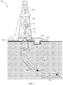
- FIG. 1 illustrates a land-based oil and gas rig 100 including, in this example, a downhole sag sensor 220, according to one or more embodiments. It should be noted that, even though FIG. 1 depicts a land-based oil and gas rig 100, it will be appreciated by those skilled in the art that the components of the rig 100, and various embodiments of the components disclosed herein, are equally well suited for use in other types of rigs, such as offshore platforms, or rigs used in any other geographical location.
- the rig 100 includes a drilling platform 102 that supports a derrick 104 having a traveling block 106 for raising and lowering a drill string 108.
- a kelly 110 supports the drill string 108 as it is lowered through a rotary table 112.
- the kelly 110 may be, for example, a four or six-sided pipe configured to transfer rotary motion to a turntable 130 and the drill string 108.
- a drill bit 114 is driven either by a downhole motor (not shown in FIG. 1 ) and/or via rotation of the drill string 108 from the drilling platform 102 and may include one or more drill collars 127 and 128.
- a pump 120 circulates a drilling fluid (i.e., mud) 126 through a feed pipe 122 to the kelly 110, which conveys the drilling fluid 126 downhole through an interior conduit in the drill string 108 and through one or more orifices in the drill bit 114.
- the drilling fluid 126 is then circulated back to the surface via the annulus defined between the drill string 108 and the borehole 116 where it is eventually deposited in a retention pit 124.
- cuttings laden fluid is processed through solids control equipment such as shakers and centrifuges (not shown in FIG.
- the drilling fluid 126 transports cuttings and debris derived from the borehole 116, aids in maintaining the integrity of the borehole 116 and provides cooling and lubrication of the drill bit 114.
- the drilling fluid 126 may include at least one weighting material suspended therein or otherwise associated therewith.
- weighting materials are dense particulate materials added to drilling fluids 126 to increase the density of the drilling fluid 126, thereby assisting in carrying cuttings from the drill bit 114 to the surface as well as managing the hydrostatic pressure in the borehole 116.
- the weighting material may be barite (BaSO 4 ), a dense sulfate mineral that naturally occurs and typically in depositional environments.
- the weighting material may include, but is not limited to, hematite, ilmenite, manganese tetraoxide, galena, and calcium carbonate.
- the borehole 116 may be generally characterized as a deviated or angled borehole that includes various sections or portions extending at different angular directions.
- the borehole 116 may include a vertical section 116A extending generally from the rig 100, an angled section 116B extending from the vertical section 116A, and a horizontal section 116C extending generally from the angled section 116C.
- a vertical section 116A extending generally from the rig 100
- an angled section 116B extending from the vertical section 116A
- a horizontal section 116C extending generally from the angled section 116C.
- the drill string 108 may include a pressure sensor 130 disposed thereon and generally located near the drill bit 114.
- the pressure sensor 130 may be a pressure-while-drilling (PWD) sensor.
- the disclosed system may also include one or more sag sensors 220 arranged along the drill string 108. The location of the sag sensors 220 are discussed in greater detail with respect to FIG. 4 .
- FIGS. 2A-2D depicted are illustrative example sequential stages of sag in the borehole 116, according to one or more embodiments.
- FIGS. 2A-2D generally depict the transition from the angled section 116B of the borehole 116 to the horizontal section 116C.
- FIG. 2A depicts normal drilling operations wherein the drill string 108 is advancing within the borehole 116 and drilling mud 126 is being returned to the surface through the annulus defined between the drill string 108 and the walls of the borehole 116, as indicated by the arrows 127.
- FIG. 1 depicted are illustrative example sequential stages of sag in the borehole 116, according to one or more embodiments.
- FIGS. 2A-2D generally depict the transition from the angled section 116B of the borehole 116 to the horizontal section 116C.
- FIG. 2A depicts normal drilling operations wherein the drill string 108 is advancing within the borehole 116 and drilling mud 126 is being returned to the
- FIG. 2B is a qualitative depiction of the transition point within the borehole 116 during a period of non-operation, such as when the drilling fluid 126 ceases to circulate. As illustrated, a time T1 has passed since the cessation of drilling fluid 126 flow, and the drill string 108 has been omitted from FIG. 2B for clarity.
- the weighting material suspended therein may start to settle within the drilling fluid 126, as generally indicated by arrows 200.
- time T1 the weighting material near the upper portions of the borehole 116 may have descended or otherwise settled into the lower portions of the borehole 116, thereby starting to result in the congregation of a lighter fluid 126L near the upper side of the borehole 116 and a heavier fluid 126H near the bottom side.
- the layers of the two fluids 126L and 126H in the angled portion 116B generally follow the angle of the borehole section 116B, as the settling is vertical rather than aligned with the borehole section 116B.
- FIG. 2C shows qualitatively how a circulating flow will form locally within the angled section 116B and the horizontal section 116C.
- the drill string 108 has again been omitted from FIG. 2C for clarity.
- the lighter fluid 126L will tend to flow upward within the angled section 116B, and thereby draw additional lighter fluid 126L from the horizontal section 116C.
- the heavier fluid 126H tends to flow downward within the angled section 116B and flow into the horizontal section 116C.
- the drilling fluid 126 will be generally distributed as shown in FIG. 2C with circulation currents within the fluids 126L and 126H as indicated by arrows 205 and 210, respectively. It can be seen that the amount of the lighter fluid 126L remaining in the horizontal section 116C is less than the amount present at time T2, shown in FIG. 2B .
- FIG. 2D qualitatively shows a general distribution of the lighter and heavier fluids 126L and 126H at a time T3, after additional time has passed following the time T2 ( FIG. 2C ).
- the heavier fluid 126H has generally congregated and otherwise filled the horizontal section 116C and the lower portion of the angled section 116B, with the lighter fluid 126L generally congregating or otherwise filling the upper angled section 116B.
- At least one problem that may occur when the heavier drilling fluid 126H settles as shown in FIG. 2D is that the pump 120 ( FIG. 1 ) may require higher pressure to initiate flow thus causing the formation to be exposed to higher and potentially destabilizing pressure.
- the lighter drilling fluid 126L nearer the surface is pumped out first, leaving the borehole 116 filled with the settled heavier drilling fluid 126H and the homogeneous drilling fluid 126 that is being pumped down the drill string 108.
- the hydrostatic pressure at the bottom of the borehole 116 can spike to a pressure that exceeds the fracture gradient of the surrounding formation 118 ( FIG. 1 ), thereby resulting in lost circulation, formation 118 damage and/or formation 118 fracturing.
- At least one additional potential problem is that the settled weighting material may cause drag on the rotating drill string 108. As accumulated weighting material in the lower portion of the borehole 116 can be difficult to re-suspend, this drag may be an ongoing issue in the operation of the rig 100.
- FIG. 3 is a qualitative plot 300 of pressure versus time at a point near the drill bit 114 ( FIG. 1 ) when pumping of a drilling fluid 126 is resumed after a quiescent period of time, according to one or more embodiments.
- the pressure P130 is the dynamic pressure measured at the PWD sensor 130 ( FIG. 1 ) for a time period starting at the resumption of pumping after a period of non-pumping. All curves are qualitative and intended for illustration only and, therefore, relative magnitudes and time relationships should not be considered as predictive of actual pressures or relationships between pressures.
- Curves 320 and 330 represent the behavior of the well with a drilling fluid 126 having a baseline composition.
- Curve 320 is the pressure curve that would be expected if no sag has occurred, for example if the pump 120 was shut off only for a short time. The pressure will increase smoothly and asymptotically approach a stable plateau without overshoot.
- Curve 320 may be considered a baseline pressure curve for comparison to other pressure curves with other mud compositions and/or after sag has occurred.
- Curve 330 is representative of a pressure spike that may be experienced when severe sag has occurred in the baseline drilling fluid 126.
- the pressure may build slower than the baseline curve 320 then rise sharply as the lighter drilling fluid 126L ( FIG. 2D ) is displaced from the borehole 116 by the rising heavier drilling fluid 126H, with the pressure curve 330 rising to a peak value that is greater than the fracture gradient, marked P-fracture on the vertical pressure axis, of the subterranean formation surrounding the lower end of the borehole 116.
- the pressure curve 330 will drop to match the baseline curve 320.
- the damage, however, has been done and the drill rig operators are likely to face a significant amount of work to recover control of the well that may be expensive in both time and money.
- Curves 340, 350, 360, and 370 qualitatively depict the expected behavior of the same borehole and quiescent period of time as curves 320 and 330 with the addition of modifiers to the drilling fluid 126.
- Example modifiers include, but are not limited to, thixotropic materials, clay, bentonite or other 'gels,' polymers, deflocculants, and emulsifiers.
- Curves 350 and 370 represent the pressures seen after circulation of the drilling fluid 126 has been stopped for the same amount of time as for curve 330.
- Curves 340 and 350 describe the pressure versus time behavior for the drilling fluid 126 of curves 320, 330 to which has been added a "unit dose" of a particular modifier, which may be a blend of one of more materials. Addition of a single unit dose of the modifier, referred to herein as a "+1 dose,” converts the baseline drilling fluid 126 into a drilling fluid 126A. The actual amount of a unit dose is arbitrary and intended only for comparison with curves 360, 370 that reflect the addition of two unit doses of the same modifier, referred to herein as a "+2 dose,” thereby converting the baseline drilling fluid 126 into a drilling fluid 126B.
- Curve 340 reflects the effect of a +1 dose of the modifier in increasing the pumping resistance of the modified drilling fluid 126A and thereby increasing the plateau pressure of curve 340 compared to curve 320.
- the benefit of adding the modifier is seen in curve 350, where the peak pressure has been reduced, compared to curve 330, because the amount of sag that occurred in the drilling fluid 126A during the same quiescent period of time was less than the sag that occurred with the unmodified drilling fluid 126 of curve 330.
- Curves 360, 370 qualitatively show the increased effect of doubling the amount of chemical modifier added to the drilling fluid 126. It should be apparent to those of skill in the art that the relative changes are illustrative only and the true effects may not be linear with the amount of added chemical modifier and are very dependent upon the type of composition of the base drilling fluid as well as the choice of chemicals that make up the chemical modifier.
- the addition of two unit doses of the chemical modifier can be seen to increase the pressure plateau of curve 360 in the absence of sag, as the drilling fluid 126B will have even more pumping resistance than the +1 dose drilling fluid 126A of curve 340.
- Curve 370 illustrates that when sag occurs in the +2 dose drilling fluid 126B, however, the peak pressure is further reduced compared to the +1 dose curve 350.
- modifier to be added to the drilling fluid 126 is a balance between sag reduction and accepting an increase in the on-going pumping resistance.
- Unnecessarily adding a modifier having the effects shown in FIG. 3 may create problems with the pumping equipment due to the added pumping resistance of the modified drilling fluids 126A, 126B, or decrease the amount of suspended cutting that settle out of the drilling fluids 126A, 126B in the retention pit 124.
- Detection of sag in real time may enable operators to avoid unnecessarily adding modifiers to the drilling fluid 126, thereby enabling them to take corrective action only when sag occurs.
- Such corrective actions may include, but are not limited to, product dosing to change the settling characteristics of the fluid, fluid circulation to mix and displace the settling/sagging fluid, changing the rate of rotation of the drill string 108, changing the tripping speed and tripping with pumping.
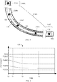
- FIG. 4 illustrated is a simplified diagram of a portion of a deviated or angled borehole 116 showing an exemplary arrangement of distributed sag sensors 220, according to one or more embodiments. In particular, FIG.
- FIG. 4 shows a curved section 116B between a generally vertical section 116A and a generally horizontal section 116C of the borehole 116.
- four sag sensors 220A, 220B, 220C, and 220D have been placed in the drill string 108 at various separated points that are distributed through the curved section 116B.
- a PWD sensor 130 is also visible near the drill bit 114.
- the annulus defined between the drill string 108 and the walls of the borehole 116 is filled with drilling fluid 126.
- the shading of the fluid 126 is intended to indicate the relative density of the local drilling fluid 126, with the drilling fluid 126 having a baseline density in the regions surrounding the PWD sensor 130 and the sag sensor 220A.
- the drilling fluid 126 has partially separated within the angled section 116B, wherein the fluid surrounding sag sensor 220B may exhibit the lowest density, the drilling fluid 126 surrounding the sag sensor 220C may exhibit an intermediate density, and the drilling fluid 126 surrounding the sag sensor 220D may exhibit the highest density. Pressures at the various sensors 130, 220A-D are discussed in greater detail with respect to FIG. 5 .
- the number of distributed sag sensors 220 may vary in various embodiments. In certain embodiments, only one sag sensor 220 may be required so long as the sag sensor 220 is positioned within the region of the sagged drilling fluid 126, either within the heavier drilling fluid 126H or the lighter drilling fluid 126L in the angled section 116B.
- Suitable sag sensors 220 may include any pressure sensor known to those skilled in the art, or any sensor that enables the computation of density or direct measurement of density in a fluid.
- the sag sensors 220 may include, but are not limited to, sensors using infrared density-measurement methods, sensors using direct-density measurement methods, and sensors using vibratory density-measurement methods.
- the sag sensor 220 may be a sensor configured to measure or detect a physical property or characteristic of the drilling fluid 126 disposed within the bore hole 116, for example viscosity, conductivity, magnetic field strength, optical transparency, absorptivity of electromagnetic radiation, etc. This property may have a known correlation with density for the particular composition of the drilling fluid 126 and, therefore, the density of the drilling fluid 126 can be determined based on measurement of the physical property or characteristic. While the disclosure is presented in terms of sensors that directly measure pressure, any sensor that measures or detects one or more physical properties or characteristics of a fluid may be substituted in place of the sag sensors 220 without departing from the scope of this disclosure.
- the sag sensor 220 may be an optical computing device that employs an integrated computational element (ICE), also known as a multivariate optical element (MOE).
- ICE integrated computational element
- MOE multivariate optical element
- Such optical computing devices may be configured to receive an input of electromagnetic radiation from the drilling fluid 126, and produce an output of electromagnetic radiation from an ICE element arranged therein.
- the electromagnetic radiation that optically interacts with the ICE element is changed so as to be readable by a detector, such that an output of the detector can be correlated to at least one characteristic of the drilling fluid 126 being measured or monitored.
- the output of electromagnetic radiation from the ICE element can be reflected electromagnetic radiation, transmitted electromagnetic radiation, and/or dispersed electromagnetic radiation.
- Whether reflected or transmitted electromagnetic radiation is analyzed by the detector may be dictated by the structural parameters of the optical computing device as well as other considerations known to those skilled in the art.
- emission and/or scattering of the drilling fluid 126 can also be monitored by such optical computing devices.
- suitable structural components for the exemplary optical computing devices are described in commonly owned U.S. Pat. Nos. 6,198,531 ; 6,529,276 ; 7,123,844 ; 7,834,999 ; 7,911,605 ; 7,920,258 ; 8,049,881 ; and 8,208,147 , and U.S. Pat. App. Serial Nos. 12/094,465 and 13/456,467 .
- the sag sensor 220 may be an optical computing device including an ICE element configured to detect or otherwise measure the spectral fingerprint of a particular weighting material, such as barite, and thereby determine the concentration of the weighting material within the drilling fluid 126.
- the sag sensor 220 may be an optical computing device including an ICE element configured to detect or otherwise measure the spectral fingerprint of a base oil in an oil-based drilling fluid 126. A change in the concentration of the weighting material will cause a corresponding change in the concentration of the base oil, and it may be more desirable to measure the concentration of the base oil than the weighting material.
- the sag sensor 220 may be an optical computing device including an ICE configured to detect or otherwise measure the spectral fingerprint of water, as measuring the concentration of water in a water-based drilling fluid 126 may be desirable for the same reasons as discussed above with regard to an oil-based drilling fluid 126.
- a spectral fingerprint is an intensity versus frequency pattern of light that is received from the substance being examined, wherein a material will have a particular pattern that is referred to as the "spectral fingerprint" of that material as detection of that pattern is indicative of the presence of that material.
- a spectral fingerprint of the drilling fluid 126 can be developed by separating light coming from the drilling fluid 126, e.g. light coming from a source and reflected by the drilling fluid 126, can be measured at a plurality of different frequencies. Each component of the drilling fluid 126 will contribute to the relative intensities at the plurality of frequencies according to the percentage amount of that component in the drilling fluid 126, and therefore the amount of the component can be derived from the combined spectral fingerprint of the drilling fluid 126. Once the amount of each component of the drilling fluid 126 is known, a total density of the measured drilling fluid 126 can be calculated.
- sag is, in actuality, the formation of a density gradient within the borehole 116 as the weighting material settles, sag may be more easily detected by measuring the pressures at various points within the portion of the borehole in which settling is occurring. Pressure can be considered an indirect indication of settling, as the pressure at any specific point is dependent upon the density of the fluids above that point and the settling of weighting material from above the point to below the point will cause a change in pressure as the settling progresses.
- the density may be measured either directly or calculated indirectly, for example by measurement of the concentration of one or more components of the drilling fluid 126 and calculation of the density based on known densities of the components, or measurement of the pressure within the borehole 116 and calculation of the density based on a sag model using the actual borehole 116 and drilling fluid 126.
- FIGS. 5-7 qualitatively discuss the results of repeated pressure measurements taken at various points along a borehole 116 and the amount of sag that is indicated by the pressure measurements. While the use of a sag model is not directly discussed, the amount of sag is determined from pressure measurements using such a model for, in this example, the borehole 116 and sensors 130 and 220A-220D shown in FIG. 4 . While sag may be considered, for a strict interpretation of "sag,” to start immediately upon cessation of circulation, a "sag event" is typically considered to be an amount of sag that has progressed sufficient to potentially present a problem of some sort.
- sag is typically evaluated for as an overall condition and not at single points within the borehole 116.
- a series of pressure measurements taken by single pressure sensor, e.g. sag sensor 220C, within a region in which sag is occurring, e.g. the angled borehole portion 116B may be sufficient to determine the overall amount of sag that is occurring over time and identify or, in certain embodiments, predict the point in time at which a problematic amount of sag, i.e. severe sag, has occurred or will occur.
- Time T0 represents the time of cessation of circulation of the drilling fluid 126 within the borehole 116 and the pressures P130, P220A, P220B, P220C, and P220D at T0 represent the initial static pressures at the locations of the respective sensors 130 and 220A-220D.
- the curves shown in FIG. 5 are illustrative in nature and are not intended to represent actual pressures of a particular well unless otherwise stated. If a sag event does not occur, then the pressures P130, P220A-D would remain almost constant while the drilling fluid is quiescent except for thermal variations in the borehole 116 and the resultant minor pressure variations.
- the PWD sensor 130 is generally not able to detect sag. Even in the presence of sag, the pressure P130 at the location of the PWD sensor 130 may remain relatively constant over time, as the total weight of the drilling fluid 126 above the PWD sensor 130 remains constant although the weighting materials may settle within the section 116B of the borehole 116.
- the problem with the PWD sensor 130 is that the hydrostatic pressure in the drilling fluid 126 is being measured in the wrong place to accurately detect a sag event.
- distributing a plurality of sensors, such as sensors 220A-D, along the drill string 108 can provide near-real-time detection of a sag event so as to allow the timely implementation of mitigation methods.
- the hydrostatic pressure P220A at the location of sag sensor 220A, which is disposed within the vertical section 116A, may also remain relatively constant over the time period of interest shown in FIG. 5 . While sag will eventually occur in the vertical section 116A, it is the accelerated sag that occurs in the angled section 116B due to the boycott effect, discussed above, that presents the greater concern. Severe sag, i.e., sag that is sufficient to create a pressure spike or drag problems for the drill string 108, may develop in the angled section 116B long before the same problem manifests itself in the vertical section 116A, and so the time period of interest in FIG. 5 is sufficiently shortened that the amount of sag that occurs in the vertical section 116A is not significant.
- the pressures at the locations of the three sag sensors 220B, 220C, and 220D plotted as pressures P220B, P220C, and P220D, respectively, in FIG. 5 , that are distributed through the angled section 116B, may gradually decrease as the weighting material settles below each of the respective sensors 220B-220C.
- a simulation or computer model may be constructed that may predict the pressure at any location within the borehole 116 and at any time for a given amount of sag.
- FIG. 6 depicts the theoretical pressures P220B, P220C, and P220D, recorded at the three sag sensors 220B, 220C, and 220D, as dashed lines.
- the measured pressures are represented as the solid lines.
- the characteristic of interest is the total pressure drop from the baseline pressure that was measured at time T0 and indicated in FIG. 6 as the horizontal dashed lines at P220B, P220C, and P220D. The total pressure drop at each time T1, T2, etc.
- ⁇ P-D-T1 is the pressure drop from baseline at sag sensor 220D at time T1.
- the severity of the sag event can be determined and, if warranted, remediation actions may then be undertaken.
- an average density change may be computed using the model of the borehole 116 and drilling fluid 126 and the average compared to one or more thresholds to determine whether sag has occurred or whether the sag is severe enough to warrant corrective action.
- the local density changes at the three sag sensors 220B, 220C, and 220D may be computed using the model of the borehole 116 and individually compared to one or more thresholds to determine whether sag has occurred or whether the sag is severe.
- FIG. 7 is another embodiment of a method of determining whether sag has occurred and estimating the severity of the sag using the slope of the measured pressure.
- a differential pressure drop dP-D for sensor 220D may be determined from pressures P220-T1 and P220-T1+dT measured at a first time T1 and a second time T1+dT. From the differential pressure drop dP-D (P220-T1+dT - P220-T1) and the differential time dT (T1+dT - T1), an instantaneous measured slope of the pressure curve P220D can be determined.
- the measured slope of pressures curves P220B and P220C may be determined.
- a theoretical instantaneous slope of pressure curves P220B, P220C, and P220D may be computed using the model of the borehole 116.
- one or more of the measured slopes and the theoretical slopes may be individually compared to one or more thresholds to determine whether sag has occurred or whether the sag is severe.
- the terms dP/dt for each of the pressure curves P220B, P220C, and P220D may be combined with the model to calculate a single average differential density dDen/dt and compared to one or more thresholds to determine whether sag has occurred or whether the sag is severe. It will be apparent to those of skill in the art that the measured and theoretical slopes may be compared to each other or combined with the sag model and then compared to a threshold in other ways without departing from the scope of this disclosure.
- FIG. 8 is a block diagram of an embodiment of an exemplary sag detection system 500, according to one or more embodiments.
- the system 500 may include one or more sensors 530 used to detect or otherwise measure pressure of a drilling fluid 126 within the borehole 116.
- the sensors 530 may be similar to one or more of the sensors 220A-D of FIG. 4 .
- the sensors 530 may be communicatively connected to a processor 510 which may communicate with a non-volatile memory 520.
- the processor 510 may be configured to receive pressure measurements from the sensors 530 and process the measurements according to instructions retrieved from the memory 520.
- the memory 520 may contain a computer model adapted to predict pressures at various points in a borehole 116 based on at least one of a borehole dimension and a characteristic of the drilling fluid 126 disposed within the borehole 116.
- the processor 510 may predict a pressure at a certain point in the borehole 116 at least partially based on the model and compare the predicted pressure to a measured pressure. In certain embodiments, the processor 510 may then communicate the results to a user for consideration.
- the processor 510 may be configured to transmit the results (either wired or wirelessly) to a user interface 540 configured to display the results of the comparison such that the operator may make an informed decision as to the status of the borehole 116.
- the processor 510 may provide alerts or alarms through the user interface 540 based at least partially on the comparison. The alerts or alarms may warn the operator of the onset of a sag event.
- the user interface 540 may contain one or more of a display screen (e.g., a graphical user interface, or the like), a printer, a network interface communicatively coupled to a remote system, an audio output device such as a speaker, a visual output device such as a flashing light, a pager, a cell phone, a radio, or other device adapted to communicate information to the operator.
- the system 500 may be further configured to accept information from the PWD sensor 130.
- FIG. 9 is a flow diagram 600 of an exemplary method 600 of detecting and responding to the onset of a sag event, according to one or more embodiments.
- the method 600 obtains measurements from one or more sag sensors 220 that may be distributed along the drill string 108, as at 610.
- a sag model may then be employed to predict pressures at the locations of the sag sensors 220 and the measured pressures are compared to the predicted pressures using, for example, one of the methods shown in FIGS. 6 and 7 , as at 620.
- the amount of settling that has occurred is then determined, as reflected in a change in density of the drilling fluid 126, and the location along the drill string 108 where the weighting material has settled, as at 630.
- the method 600 then proceeds to determine whether the settling constitutes sag, as at 640. In one or more embodiments, whether sag has indeed occurred may be determined through a comparison of a density or change in density to a predetermined threshold or model. If the determined amount of settling does not constitute problematic sag, then the method 600 returns to 610 to obtain additional pressure measurements from the sensors.
- the method 600 then proceeds to determine whether the sag is severe, as at 650. In one or more embodiments, whether the sag event is severe may be determined through a comparison of a density or change in density to a threshold. If the sag is determined to be severe, the method 600 may proceed via a first algorithm to provide several possible actions to pursue, as at 660. Possible actions include, but are not limited to, an alarm, starting the pump 120 in order to circulate the drilling fluid 126, pumping while tripping, e.g. pulling the drill string 108 from the borehole 116 so as to replace a drill bit 114, adding a modifier in the form of a dose mud to the drilling fluid 126, or other actions as described or combinations of several actions above with respect to FIG. 3 .
- the method 600 may proceed via a second algorithm to provide several other possible actions to pursue, as at 670. Possible actions include, but are not limited to, notifying the operator of the onset of a sag event within the borehole 116, adding a modifier in the form of a dose mud to the drilling fluid 126, modifying the current operation of the drill rig 100, or other actions as described above with respect to FIG. 3 .
- the method 600 may return to start a new cycle of measurement and analysis, as at 610. In one or more embodiments, this cycle continues until drilling operations are concluded and the drilling fluid 126 is completely circulated out of the borehole 116.
- Embodiment A A method of detecting sag in a drilling fluid within a borehole, the method comprising: measuring a first pressure at a first time at a point within the borehole; predicting a characteristic of the drilling fluid at the point using a computer model, thereby obtaining a predicted characteristic; calculating the characteristic based on the first pressure, thereby obtaining a calculated characteristic; and determining whether sag has occurred based on a comparison between the calculated characteristic and the predicted characteristic.
- exemplary combinations applicable to embodiment A include: a combination of A with elements A1 and A4; a combination of A with elements A3 and A4; a combination of A with elements A1 and A7; etc.
- Embodiment B system for detecting sag in a drilling fluid within a borehole, comprising: at least one sensor positioned within the borehole at a point, the sensor being configured to measure a characteristic of the drilling fluid at a first time and provide a measured characteristic; and a processor communicatively coupled to the at least one sensor and configured to receive the measured characteristic and predict a theoretical characteristic of the drilling fluid at the point, the processor being further configured to determine whether sag has occurred at the first time based on a comparison between the measured characteristic and the theoretical characteristic.
- exemplary combinations applicable to embodiment B include: a combination of B with elements B1 and B7; a combination of B with elements B2 and B8; a combination of B with elements B5 and B6; etc.
Description
- The present invention relates to detection of sag in a drilling fluid and, in particular, to the real-time detection and measurement of sag within a deviated borehole.
- While drilling a gas or oil well, a drilling fluid, i.e. mud, is typically pumped down to the drill bit during drilling operations and flowed back to the surface through the annulus defined between the drill string and the walls of the borehole. A typical drilling fluid includes a weighting material, such as barite, to increase the density of the drilling fluid and thereby assist in transporting rock chips and cuttings from the drill bit to the surface.
- Settling or migration of the suspended weighting materials within the drilling fluid is commonly referred to as "sag" or "barite sag," and is a known and persistent problem in drilling operations. Turbulence in the moving fluid may tend to keep particles in suspension, but when the drilling fluid becomes static, such as while tripping the drill bit or when the circulation flow rate of the drilling fluid is relatively low, the weighting material(s) may tend to settle toward the bottom of the borehole.
- When sag occurs in a borehole, i.e. "a sag event," it can cause borehole pressure problems that are typically manifested when the mud pumps are turned on after quiescent periods, or during operations such as tripping in when the fluids are periodically sheared and then circulation resumed. Problematic borehole pressure spikes may occur when the drilling fluid is pumped after a sag event. The lighter drilling fluid nearer the surface is pumped out first, leaving the borehole filled with the heavier, settled drilling fluid and the newly introduced drilling fluid that is being pumped down the drill string. As the borehole is now filled with a heavier fluid, on average, and the heavier fluid may have a greater flow resistance than the original fluid and/or higher hydrostatic pressure, the borehole pressure at depth can exceed the fracture gradient of the surrounding formation, resulting in lost circulation, formation damage and/or fracturing of the formation.
- Sag is aggravated in deviated or angled boreholes due to a phenomenon called "boycott settling" or the "boycott effect." Briefly, the boycott effect occurs since suspended particles tend to settle vertically downward, creating an increased-density or heavier layer along the lower side of the angled borehole and a reduced-density or lighter layer along the upper side. Such a pressure imbalance across the longitudinal cross-section of the angled borehole will tend to circulate the lighter layer upward and the heavier layer downward, significantly increasing the rate at which the heavier particles accumulate in the lower portion of the angled borehole. Accumulations of the weighting material in the lower portion of the borehole can be difficult to re-suspend and may cause drag on rotating drill strings or impede moving tools up or down through the region of accumulated weighting material.
- Historically, sag mitigation has been focused on increasing the low-end rheology such as through modifying the drilling fluid to increase the viscosity at low flow rates, or using smaller-diameter weighting materials, or both. One conventional method of monitoring a borehole for sag includes periodic measurement of the density of the returning mud to detect variations which may indicate that sag is occurring somewhere within the borehole. Another conventional method is to monitor the standpipe pressure as fluctuations in the pressure may indicate non-uniform flow resistance within the borehole. These methods are indirect, at best, and the variations in mud density and pressure may be caused by factors unrelated to sag.
- Those skilled in the art will readily recognize the importance in accurately determining the onset of sag, particularly in angled or deviated wells, which can adversely affect hydrocarbon production. In some cases, the operation of a well from a particular reservoir can be permanently degraded due to resistance or blockage by settled weighting material, making prevention essential to proper reservoir management. Accordingly, identifying a sag event before it becomes severe can prove advantageous in mitigating costly corrective action.
-
US 6,176,323 B1 discloses drilling systems with sensors for determining properties of drilling fluid downhole. - However,
US 6,176,323 B1 does not disclose predicting a theoretical pressure slope and calculating a pressure slope based on a first and second pressure and a first and second time, and determining whether sag has occurred by comparing the difference between the theoretical pressure slope and the pressure slope to a threshold. - In a first aspect of the present invention, there is provided a method according to
claim 1. - In a second aspect of the present invention, there is provided a system according to claim 9.
- The following figures are included to illustrate certain aspects of the present invention, and should not be viewed as exclusive embodiments. The subject matter disclosed is capable of considerable modifications, alterations, combinations, and equivalents in form and function, as will occur to those skilled in the art and having the benefit of this disclosure.
-
FIG. 1 illustrates a land-based oil and gas rig including one or more sensors that may be employed to detect sag, according to one or more embodiments. -
FIGS. 2A-2D depict illustrative example sequential stages of sag in anangled borehole 116, according to one or more embodiments. -
FIG. 3 is a qualitative plot of pressures near the drill bit when pumping of a drilling fluid is resumed after a quiescent period of time, according to one or more embodiments. -
FIG. 4 is a simplified diagram of a portion of an inclined borehole showing an exemplary arrangement of distributed sensors, according to one or more embodiments. -
FIG. 5 is a qualitative plot of pressures at the various sensor locations ofFIG. 4 during a sag event, according to one or more embodiments. -
FIGS. 6 and 7 illustrate exemplary methods of evaluating pressures at the distributed sensors ofFIG. 4 , according to one or more embodiments. -
FIG. 8 is a block diagram of an embodiment of a sag detection system, according to one or more embodiments. -
FIG. 9 is a flow diagram of an exemplary method of detecting and responding to the detection of a sag event, according to one or more embodiments. - The present invention relates to detection of sag in a drilling fluid and, in particular, to the real-time detection and measurement of sag within a deviated borehole.
- Disclosed herein are systems and methods of determining the onset of weighting material settling and sag in real time as occurring in a deviated or angled borehole. Once sag has occurred, it may require normal operations to be suspended while specific sag mitigation procedures are implemented. If the sag is severe, it may be difficult to recover completely, and the long-term productivity of the well may be reduced. In a worst case, for example if the settled weighting material has formed a hard mass around the drill string, it may not be possible to recover operations and the well may be lost. The disclosed systems and methods may prove advantageous in detecting sag at a much earlier stage at which point drilling operations may be redirected or changed in order to minimize the problematic effects. In some cases, early detection of sag may allow an operator to proactively treat the borehole, such as by altering the dosing of the fluid system as a corrective step or action. The disclosed systems and methods may further provide real time feedback on the effectiveness of such corrective actions or treatments.
-
FIG. 1 illustrates a land-based oil andgas rig 100 including, in this example, adownhole sag sensor 220, according to one or more embodiments. It should be noted that, even thoughFIG. 1 depicts a land-based oil andgas rig 100, it will be appreciated by those skilled in the art that the components of therig 100, and various embodiments of the components disclosed herein, are equally well suited for use in other types of rigs, such as offshore platforms, or rigs used in any other geographical location. - As illustrated in
FIG. 1 , therig 100 includes adrilling platform 102 that supports aderrick 104 having atraveling block 106 for raising and lowering adrill string 108. A kelly 110 supports thedrill string 108 as it is lowered through a rotary table 112. The kelly 110 may be, for example, a four or six-sided pipe configured to transfer rotary motion to aturntable 130 and thedrill string 108. Adrill bit 114 is driven either by a downhole motor (not shown inFIG. 1 ) and/or via rotation of thedrill string 108 from thedrilling platform 102 and may include one ormore drill collars bit 114 rotates, it creates aborehole 116 that passes through various subterranean formations 118. Apump 120 circulates a drilling fluid (i.e., mud) 126 through a feed pipe 122 to thekelly 110, which conveys thedrilling fluid 126 downhole through an interior conduit in thedrill string 108 and through one or more orifices in thedrill bit 114. Thedrilling fluid 126 is then circulated back to the surface via the annulus defined between thedrill string 108 and theborehole 116 where it is eventually deposited in aretention pit 124. Typically, cuttings laden fluid is processed through solids control equipment such as shakers and centrifuges (not shown inFIG. 1 ) to remove cuttings and debris prior to being returned toretention pit 124. Thedrilling fluid 126 transports cuttings and debris derived from theborehole 116, aids in maintaining the integrity of theborehole 116 and provides cooling and lubrication of thedrill bit 114. - The
drilling fluid 126 may include at least one weighting material suspended therein or otherwise associated therewith. As known in the art, weighting materials are dense particulate materials added todrilling fluids 126 to increase the density of thedrilling fluid 126, thereby assisting in carrying cuttings from thedrill bit 114 to the surface as well as managing the hydrostatic pressure in theborehole 116. In one embodiment, the weighting material may be barite (BaSO4), a dense sulfate mineral that naturally occurs and typically in depositional environments. In other embodiments, the weighting material may include, but is not limited to, hematite, ilmenite, manganese tetraoxide, galena, and calcium carbonate. - As illustrated in
FIG. 1 , theborehole 116 may be generally characterized as a deviated or angled borehole that includes various sections or portions extending at different angular directions. Specifically, theborehole 116 may include avertical section 116A extending generally from therig 100, anangled section 116B extending from thevertical section 116A, and ahorizontal section 116C extending generally from theangled section 116C. Those skilled in the art will readily recognize that, while theangled section 116B is shown as a generally straight section of thebore hole 116 with short curved sections at each end, the entireangled section 116B may be curved or otherwise exhibit one or more arcuate portions, without departing from the scope of the disclosure. - The
drill string 108 may include apressure sensor 130 disposed thereon and generally located near thedrill bit 114. In some embodiments, thepressure sensor 130 may be a pressure-while-drilling (PWD) sensor. The disclosed system may also include one ormore sag sensors 220 arranged along thedrill string 108. The location of thesag sensors 220 are discussed in greater detail with respect toFIG. 4 . - Referring now to
FIGS. 2A-2D , with continued reference toFIG. 1 , depicted are illustrative example sequential stages of sag in theborehole 116, according to one or more embodiments. In particular,FIGS. 2A-2D generally depict the transition from theangled section 116B of the borehole 116 to thehorizontal section 116C.FIG. 2A depicts normal drilling operations wherein thedrill string 108 is advancing within theborehole 116 anddrilling mud 126 is being returned to the surface through the annulus defined between thedrill string 108 and the walls of theborehole 116, as indicated by thearrows 127.FIG. 2B is a qualitative depiction of the transition point within theborehole 116 during a period of non-operation, such as when thedrilling fluid 126 ceases to circulate. As illustrated, a time T1 has passed since the cessation ofdrilling fluid 126 flow, and thedrill string 108 has been omitted fromFIG. 2B for clarity. - Once the
drilling fluid 126 ceases flowing up theborehole 116, the weighting material suspended therein may start to settle within thedrilling fluid 126, as generally indicated byarrows 200. After time T1 has passed, the weighting material near the upper portions of the borehole 116 may have descended or otherwise settled into the lower portions of theborehole 116, thereby starting to result in the congregation of alighter fluid 126L near the upper side of theborehole 116 and aheavier fluid 126H near the bottom side. It can be seen that the layers of the twofluids angled portion 116B generally follow the angle of theborehole section 116B, as the settling is vertical rather than aligned with theborehole section 116B. - As the
drilling fluid 126 begins to separate into the twofluids borehole 116 due to the differing densities of the twofluids FIG. 2C shows qualitatively how a circulating flow will form locally within theangled section 116B and thehorizontal section 116C. Thedrill string 108 has again been omitted fromFIG. 2C for clarity. Thelighter fluid 126L will tend to flow upward within theangled section 116B, and thereby draw additionallighter fluid 126L from thehorizontal section 116C. At the same time, theheavier fluid 126H tends to flow downward within theangled section 116B and flow into thehorizontal section 116C. At a time T2 (i.e., some time after the time T1) of the configuration shown inFIG. 2B , thedrilling fluid 126 will be generally distributed as shown inFIG. 2C with circulation currents within thefluids arrows lighter fluid 126L remaining in thehorizontal section 116C is less than the amount present at time T2, shown inFIG. 2B . -
FIG. 2D qualitatively shows a general distribution of the lighter andheavier fluids FIG. 2C ). As illustrated, theheavier fluid 126H has generally congregated and otherwise filled thehorizontal section 116C and the lower portion of theangled section 116B, with thelighter fluid 126L generally congregating or otherwise filling the upperangled section 116B. At least one problem that may occur when theheavier drilling fluid 126H settles as shown inFIG. 2D is that the pump 120 (FIG. 1 ) may require higher pressure to initiate flow thus causing the formation to be exposed to higher and potentially destabilizing pressure. Thelighter drilling fluid 126L nearer the surface is pumped out first, leaving the borehole 116 filled with the settledheavier drilling fluid 126H and thehomogeneous drilling fluid 126 that is being pumped down thedrill string 108. As a result, the hydrostatic pressure at the bottom of the borehole 116 can spike to a pressure that exceeds the fracture gradient of the surrounding formation 118 (FIG. 1 ), thereby resulting in lost circulation, formation 118 damage and/or formation 118 fracturing. - At least one additional potential problem is that the settled weighting material may cause drag on the
rotating drill string 108. As accumulated weighting material in the lower portion of the borehole 116 can be difficult to re-suspend, this drag may be an ongoing issue in the operation of therig 100. -
FIG. 3 is aqualitative plot 300 of pressure versus time at a point near the drill bit 114 (FIG. 1 ) when pumping of adrilling fluid 126 is resumed after a quiescent period of time, according to one or more embodiments. In this example, the pressure P130 is the dynamic pressure measured at the PWD sensor 130 (FIG. 1 ) for a time period starting at the resumption of pumping after a period of non-pumping. All curves are qualitative and intended for illustration only and, therefore, relative magnitudes and time relationships should not be considered as predictive of actual pressures or relationships between pressures. -
Curves drilling fluid 126 having a baseline composition.Curve 320 is the pressure curve that would be expected if no sag has occurred, for example if thepump 120 was shut off only for a short time. The pressure will increase smoothly and asymptotically approach a stable plateau without overshoot.Curve 320 may be considered a baseline pressure curve for comparison to other pressure curves with other mud compositions and/or after sag has occurred. -
Curve 330 is representative of a pressure spike that may be experienced when severe sag has occurred in thebaseline drilling fluid 126. The pressure may build slower than thebaseline curve 320 then rise sharply as thelighter drilling fluid 126L (FIG. 2D ) is displaced from the borehole 116 by the risingheavier drilling fluid 126H, with thepressure curve 330 rising to a peak value that is greater than the fracture gradient, marked P-fracture on the vertical pressure axis, of the subterranean formation surrounding the lower end of theborehole 116. As theheavier fluid 126H is carried out of theborehole 116, thepressure curve 330 will drop to match thebaseline curve 320. The damage, however, has been done and the drill rig operators are likely to face a significant amount of work to recover control of the well that may be expensive in both time and money. -
Curves curves drilling fluid 126. Example modifiers include, but are not limited to, thixotropic materials, clay, bentonite or other 'gels,' polymers, deflocculants, and emulsifiers.Curves drilling fluid 126 has been stopped for the same amount of time as forcurve 330. -
Curves drilling fluid 126 ofcurves baseline drilling fluid 126 into a drilling fluid 126A. The actual amount of a unit dose is arbitrary and intended only for comparison withcurves baseline drilling fluid 126 into a drilling fluid 126B.Curve 340 reflects the effect of a +1 dose of the modifier in increasing the pumping resistance of the modified drilling fluid 126A and thereby increasing the plateau pressure ofcurve 340 compared tocurve 320. The benefit of adding the modifier is seen incurve 350, where the peak pressure has been reduced, compared tocurve 330, because the amount of sag that occurred in the drilling fluid 126A during the same quiescent period of time was less than the sag that occurred with theunmodified drilling fluid 126 ofcurve 330. -
Curves drilling fluid 126. It should be apparent to those of skill in the art that the relative changes are illustrative only and the true effects may not be linear with the amount of added chemical modifier and are very dependent upon the type of composition of the base drilling fluid as well as the choice of chemicals that make up the chemical modifier. The addition of two unit doses of the chemical modifier can be seen to increase the pressure plateau ofcurve 360 in the absence of sag, as the drilling fluid 126B will have even more pumping resistance than the +1 dose drilling fluid 126A ofcurve 340.Curve 370 illustrates that when sag occurs in the +2 dose drilling fluid 126B, however, the peak pressure is further reduced compared to the +1dose curve 350. - It will be apparent that the proper dosing of modifier to be added to the
drilling fluid 126 is a balance between sag reduction and accepting an increase in the on-going pumping resistance. Unnecessarily adding a modifier having the effects shown inFIG. 3 may create problems with the pumping equipment due to the added pumping resistance of the modified drilling fluids 126A, 126B, or decrease the amount of suspended cutting that settle out of the drilling fluids 126A, 126B in theretention pit 124. - Detection of sag in real time may enable operators to avoid unnecessarily adding modifiers to the
drilling fluid 126, thereby enabling them to take corrective action only when sag occurs. Such corrective actions may include, but are not limited to, product dosing to change the settling characteristics of the fluid, fluid circulation to mix and displace the settling/sagging fluid, changing the rate of rotation of thedrill string 108, changing the tripping speed and tripping with pumping. Referring now toFIG. 4 , illustrated is a simplified diagram of a portion of a deviated orangled borehole 116 showing an exemplary arrangement of distributedsag sensors 220, according to one or more embodiments. In particular,FIG. 4 shows acurved section 116B between a generallyvertical section 116A and a generallyhorizontal section 116C of theborehole 116. In this example, foursag sensors drill string 108 at various separated points that are distributed through thecurved section 116B. APWD sensor 130 is also visible near thedrill bit 114. - The annulus defined between the
drill string 108 and the walls of theborehole 116 is filled withdrilling fluid 126. The shading of the fluid 126 is intended to indicate the relative density of thelocal drilling fluid 126, with thedrilling fluid 126 having a baseline density in the regions surrounding thePWD sensor 130 and thesag sensor 220A. As illustrated, thedrilling fluid 126 has partially separated within theangled section 116B, wherein the fluid surroundingsag sensor 220B may exhibit the lowest density, thedrilling fluid 126 surrounding thesag sensor 220C may exhibit an intermediate density, and thedrilling fluid 126 surrounding thesag sensor 220D may exhibit the highest density. Pressures at thevarious sensors FIG. 5 . The number of distributedsag sensors 220 may vary in various embodiments. In certain embodiments, only onesag sensor 220 may be required so long as thesag sensor 220 is positioned within the region of the saggeddrilling fluid 126, either within theheavier drilling fluid 126H or thelighter drilling fluid 126L in theangled section 116B. -
Suitable sag sensors 220 may include any pressure sensor known to those skilled in the art, or any sensor that enables the computation of density or direct measurement of density in a fluid. For example, thesag sensors 220 may include, but are not limited to, sensors using infrared density-measurement methods, sensors using direct-density measurement methods, and sensors using vibratory density-measurement methods. - In certain embodiments, the
sag sensor 220 may be a sensor configured to measure or detect a physical property or characteristic of thedrilling fluid 126 disposed within thebore hole 116, for example viscosity, conductivity, magnetic field strength, optical transparency, absorptivity of electromagnetic radiation, etc. This property may have a known correlation with density for the particular composition of thedrilling fluid 126 and, therefore, the density of thedrilling fluid 126 can be determined based on measurement of the physical property or characteristic. While the disclosure is presented in terms of sensors that directly measure pressure, any sensor that measures or detects one or more physical properties or characteristics of a fluid may be substituted in place of thesag sensors 220 without departing from the scope of this disclosure. - In other embodiments, the
sag sensor 220 may be an optical computing device that employs an integrated computational element (ICE), also known as a multivariate optical element (MOE). Such optical computing devices may be configured to receive an input of electromagnetic radiation from thedrilling fluid 126, and produce an output of electromagnetic radiation from an ICE element arranged therein. The electromagnetic radiation that optically interacts with the ICE element is changed so as to be readable by a detector, such that an output of the detector can be correlated to at least one characteristic of thedrilling fluid 126 being measured or monitored. The output of electromagnetic radiation from the ICE element can be reflected electromagnetic radiation, transmitted electromagnetic radiation, and/or dispersed electromagnetic radiation. - Whether reflected or transmitted electromagnetic radiation is analyzed by the detector may be dictated by the structural parameters of the optical computing device as well as other considerations known to those skilled in the art. In addition, emission and/or scattering of the
drilling fluid 126, for example via fluorescence, luminescence, Raman scattering, and/or Raleigh scattering, can also be monitored by such optical computing devices. In some embodiments, suitable structural components for the exemplary optical computing devices are described in commonly ownedU.S. Pat. Nos. 6,198,531 ;6,529,276 ;7,123,844 ;7,834,999 ;7,911,605 ;7,920,258 ;8,049,881 ; and8,208,147 , andU.S. Pat. App. Serial Nos. 12/094,465 and13/456,467 - In some embodiments, the
sag sensor 220 may be an optical computing device including an ICE element configured to detect or otherwise measure the spectral fingerprint of a particular weighting material, such as barite, and thereby determine the concentration of the weighting material within thedrilling fluid 126. In other embodiments, thesag sensor 220 may be an optical computing device including an ICE element configured to detect or otherwise measure the spectral fingerprint of a base oil in an oil-baseddrilling fluid 126. A change in the concentration of the weighting material will cause a corresponding change in the concentration of the base oil, and it may be more desirable to measure the concentration of the base oil than the weighting material. For example, there may be multiple materials suspended in the drilling fluid and measurement of the concentration of the base oil may replace multiple individual measurements of the various concentrations of the multiple suspended materials. In yet other embodiments, thesag sensor 220 may be an optical computing device including an ICE configured to detect or otherwise measure the spectral fingerprint of water, as measuring the concentration of water in a water-baseddrilling fluid 126 may be desirable for the same reasons as discussed above with regard to an oil-baseddrilling fluid 126. - A spectral fingerprint is an intensity versus frequency pattern of light that is received from the substance being examined, wherein a material will have a particular pattern that is referred to as the "spectral fingerprint" of that material as detection of that pattern is indicative of the presence of that material. In a brief and simplified summary, a spectral fingerprint of the
drilling fluid 126 can be developed by separating light coming from thedrilling fluid 126, e.g. light coming from a source and reflected by thedrilling fluid 126, can be measured at a plurality of different frequencies. Each component of thedrilling fluid 126 will contribute to the relative intensities at the plurality of frequencies according to the percentage amount of that component in thedrilling fluid 126, and therefore the amount of the component can be derived from the combined spectral fingerprint of thedrilling fluid 126. Once the amount of each component of thedrilling fluid 126 is known, a total density of the measureddrilling fluid 126 can be calculated. - While sag is, in actuality, the formation of a density gradient within the
borehole 116 as the weighting material settles, sag may be more easily detected by measuring the pressures at various points within the portion of the borehole in which settling is occurring. Pressure can be considered an indirect indication of settling, as the pressure at any specific point is dependent upon the density of the fluids above that point and the settling of weighting material from above the point to below the point will cause a change in pressure as the settling progresses. While the local density of thedrilling fluid 126 is the direct physical property of interest, the density may be measured either directly or calculated indirectly, for example by measurement of the concentration of one or more components of thedrilling fluid 126 and calculation of the density based on known densities of the components, or measurement of the pressure within theborehole 116 and calculation of the density based on a sag model using theactual borehole 116 anddrilling fluid 126. -
FIGS. 5-7 qualitatively discuss the results of repeated pressure measurements taken at various points along aborehole 116 and the amount of sag that is indicated by the pressure measurements. While the use of a sag model is not directly discussed, the amount of sag is determined from pressure measurements using such a model for, in this example, theborehole 116 andsensors FIG. 4 . While sag may be considered, for a strict interpretation of "sag," to start immediately upon cessation of circulation, a "sag event" is typically considered to be an amount of sag that has progressed sufficient to potentially present a problem of some sort. Moreover, sag is typically evaluated for as an overall condition and not at single points within theborehole 116. In certain embodiments, e.g. with the use of a complete computer model that includes the dimensions and features of theborehole 116 and composition and characteristics of thedrilling fluid 126, a series of pressure measurements taken by single pressure sensor,e.g. sag sensor 220C, within a region in which sag is occurring, e.g. theangled borehole portion 116B, may be sufficient to determine the overall amount of sag that is occurring over time and identify or, in certain embodiments, predict the point in time at which a problematic amount of sag, i.e. severe sag, has occurred or will occur. - Referring now to
FIG. 5 , with continued reference toFIG. 4 , illustrated is a qualitative plot of pressures at thevarious sensor locations drilling fluid 126 within theborehole 116 and the pressures P130, P220A, P220B, P220C, and P220D at T0 represent the initial static pressures at the locations of therespective sensors FIG. 5 are illustrative in nature and are not intended to represent actual pressures of a particular well unless otherwise stated. If a sag event does not occur, then the pressures P130, P220A-D would remain almost constant while the drilling fluid is quiescent except for thermal variations in theborehole 116 and the resultant minor pressure variations. - The
PWD sensor 130 is generally not able to detect sag. Even in the presence of sag, the pressure P130 at the location of thePWD sensor 130 may remain relatively constant over time, as the total weight of thedrilling fluid 126 above thePWD sensor 130 remains constant although the weighting materials may settle within thesection 116B of theborehole 116. The problem with thePWD sensor 130 is that the hydrostatic pressure in thedrilling fluid 126 is being measured in the wrong place to accurately detect a sag event. According to the present disclosure, distributing a plurality of sensors, such assensors 220A-D, along thedrill string 108 can provide near-real-time detection of a sag event so as to allow the timely implementation of mitigation methods. - The hydrostatic pressure P220A at the location of
sag sensor 220A, which is disposed within thevertical section 116A, may also remain relatively constant over the time period of interest shown inFIG. 5 . While sag will eventually occur in thevertical section 116A, it is the accelerated sag that occurs in theangled section 116B due to the boycott effect, discussed above, that presents the greater concern. Severe sag, i.e., sag that is sufficient to create a pressure spike or drag problems for thedrill string 108, may develop in theangled section 116B long before the same problem manifests itself in thevertical section 116A, and so the time period of interest inFIG. 5 is sufficiently shortened that the amount of sag that occurs in thevertical section 116A is not significant. - The pressures at the locations of the three
sag sensors FIG. 5 , that are distributed through theangled section 116B, may gradually decrease as the weighting material settles below each of therespective sensors 220B-220C. As the mechanisms of settling, even in the presence of the boycott effect, are generally understood, a simulation or computer model may be constructed that may predict the pressure at any location within theborehole 116 and at any time for a given amount of sag. For a particular well that is circulating aparticular drilling fluid 126, theoretical hydrostatic pressures in thewellbore 116 can be calculated and compared to the pressures measured by each distributedsag sensor 220A-D. By comparing the theoretical pressures to the measured pressures at eachsag sensor 220A-D, the sag rate, i.e. density-change rate, for various annular sections of the borehole 116 can be calculated or otherwise determined. - Referring to
FIGS. 6 and 7 , with continued reference toFIG. 4 , illustrated are exemplary methods of evaluating pressures at the distributedsensors 220B-D, according to one or more embodiments.FIG. 6 depicts the theoretical pressures P220B, P220C, and P220D, recorded at the threesag sensors FIG. 6 , the characteristic of interest is the total pressure drop from the baseline pressure that was measured at time T0 and indicated inFIG. 6 as the horizontal dashed lines at P220B, P220C, and P220D. The total pressure drop at each time T1, T2, etc. is indicated by the vertical arrow, for example the arrow labeled "ΔP-D-T1" is the pressure drop from baseline atsag sensor 220D at time T1. By calculating the pressure drops ΔP-D-T1, ΔP-C-T1, etc. at times T1, T2, etc. during a sag event, the severity of the sag event can be determined and, if warranted, remediation actions may then be undertaken. In one or more embodiments, an average density change may be computed using the model of theborehole 116 anddrilling fluid 126 and the average compared to one or more thresholds to determine whether sag has occurred or whether the sag is severe enough to warrant corrective action. In one or more embodiments, the local density changes at the threesag sensors borehole 116 and individually compared to one or more thresholds to determine whether sag has occurred or whether the sag is severe. -
FIG. 7 is another embodiment of a method of determining whether sag has occurred and estimating the severity of the sag using the slope of the measured pressure. In one or more embodiments, a differential pressure drop dP-D forsensor 220D, and similar differential pressure drops for the pressures measured atother sensors borehole 116. In one or more embodiments, one or more of the measured slopes and the theoretical slopes may be individually compared to one or more thresholds to determine whether sag has occurred or whether the sag is severe. In one or more embodiments, the terms dP/dt for each of the pressure curves P220B, P220C, and P220D may be combined with the model to calculate a single average differential density dDen/dt and compared to one or more thresholds to determine whether sag has occurred or whether the sag is severe. It will be apparent to those of skill in the art that the measured and theoretical slopes may be compared to each other or combined with the sag model and then compared to a threshold in other ways without departing from the scope of this disclosure. -
FIG. 8 is a block diagram of an embodiment of an exemplarysag detection system 500, according to one or more embodiments. Thesystem 500 may include one ormore sensors 530 used to detect or otherwise measure pressure of adrilling fluid 126 within theborehole 116. In one or more embodiments, thesensors 530 may be similar to one or more of thesensors 220A-D ofFIG. 4 . Thesensors 530 may be communicatively connected to aprocessor 510 which may communicate with anon-volatile memory 520. Theprocessor 510 may be configured to receive pressure measurements from thesensors 530 and process the measurements according to instructions retrieved from thememory 520. - In certain embodiments, the
memory 520 may contain a computer model adapted to predict pressures at various points in a borehole 116 based on at least one of a borehole dimension and a characteristic of thedrilling fluid 126 disposed within theborehole 116. In certain embodiments, theprocessor 510 may predict a pressure at a certain point in the borehole 116 at least partially based on the model and compare the predicted pressure to a measured pressure. In certain embodiments, theprocessor 510 may then communicate the results to a user for consideration. - In some embodiments, the
processor 510 may be configured to transmit the results (either wired or wirelessly) to auser interface 540 configured to display the results of the comparison such that the operator may make an informed decision as to the status of theborehole 116. In one or more embodiments, theprocessor 510 may provide alerts or alarms through theuser interface 540 based at least partially on the comparison. The alerts or alarms may warn the operator of the onset of a sag event. In one or more embodiments, theuser interface 540 may contain one or more of a display screen (e.g., a graphical user interface, or the like), a printer, a network interface communicatively coupled to a remote system, an audio output device such as a speaker, a visual output device such as a flashing light, a pager, a cell phone, a radio, or other device adapted to communicate information to the operator. In one or more embodiments, thesystem 500 may be further configured to accept information from thePWD sensor 130. -
FIG. 9 is a flow diagram 600 of anexemplary method 600 of detecting and responding to the onset of a sag event, according to one or more embodiments. Starting at theSTART 601, themethod 600 obtains measurements from one ormore sag sensors 220 that may be distributed along thedrill string 108, as at 610. A sag model may then be employed to predict pressures at the locations of thesag sensors 220 and the measured pressures are compared to the predicted pressures using, for example, one of the methods shown inFIGS. 6 and 7 , as at 620. The amount of settling that has occurred is then determined, as reflected in a change in density of thedrilling fluid 126, and the location along thedrill string 108 where the weighting material has settled, as at 630. Themethod 600 then proceeds to determine whether the settling constitutes sag, as at 640. In one or more embodiments, whether sag has indeed occurred may be determined through a comparison of a density or change in density to a predetermined threshold or model. If the determined amount of settling does not constitute problematic sag, then themethod 600 returns to 610 to obtain additional pressure measurements from the sensors. - If it is determined that sag is detected, however, the
method 600 then proceeds to determine whether the sag is severe, as at 650. In one or more embodiments, whether the sag event is severe may be determined through a comparison of a density or change in density to a threshold. If the sag is determined to be severe, themethod 600 may proceed via a first algorithm to provide several possible actions to pursue, as at 660. Possible actions include, but are not limited to, an alarm, starting thepump 120 in order to circulate thedrilling fluid 126, pumping while tripping, e.g. pulling thedrill string 108 from the borehole 116 so as to replace adrill bit 114, adding a modifier in the form of a dose mud to thedrilling fluid 126, or other actions as described or combinations of several actions above with respect toFIG. 3 . - If the sag is determine to not be severe, the
method 600 may proceed via a second algorithm to provide several other possible actions to pursue, as at 670. Possible actions include, but are not limited to, notifying the operator of the onset of a sag event within theborehole 116, adding a modifier in the form of a dose mud to thedrilling fluid 126, modifying the current operation of thedrill rig 100, or other actions as described above with respect toFIG. 3 . After the first or second algorithms have completed the action selected in response to the detected sag, themethod 600 may return to start a new cycle of measurement and analysis, as at 610. In one or more embodiments, this cycle continues until drilling operations are concluded and thedrilling fluid 126 is completely circulated out of theborehole 116. - Embodiments disclosed herein include embodiments A and B:
- Embodiment A. A method of detecting sag in a drilling fluid within a borehole, the method comprising: measuring a first pressure at a first time at a point within the borehole; predicting a characteristic of the drilling fluid at the point using a computer model, thereby obtaining a predicted characteristic; calculating the characteristic based on the first pressure, thereby obtaining a calculated characteristic; and determining whether sag has occurred based on a comparison between the calculated characteristic and the predicted characteristic.
- Embodiment A may have one or more of the following additional elements in any combination:
- Element A1: The method wherein the point is above a bottom of the borehole.
- Element A2: The method wherein predicting a characteristic of the drilling fluid further comprises using at least one of a density of the drilling fluid, a rheological measurement of the drilling fluid and flow characteristics of the drilling fluid.
- Element A3: The method wherein predicting a characteristic of the drilling fluid further comprises using information regarding at least one of a diameter of the borehole, an angle of a portion of the borehole, a length of an angled portion of the borehole, and an outer diameter of a drill string.
- Element A4: The method wherein: predicting the characteristic of the drilling fluid further comprises predicting a theoretical first pressure at the point, the theoretical first pressure being indicative of an absence of sag; and determining whether sag has occurred further comprises comparing a difference between the first pressure and the theoretical first pressure to a threshold, where, if the difference is greater than the threshold, sag has occurred.
- Element A5: The method wherein the theoretical first pressure comprises a hydrostatic pressure.
- Element A6: The method wherein the threshold is calculated based at least in part on a time interval from a cessation of flow of the drilling fluid to the first time.
- Element A7: The method further comprising measuring a second pressure at the point at a second time that is after the first time, and wherein: predicting the characteristic of the drilling fluid further comprises predicting a theoretical pressure slope between the first and second times; calculating the characteristic further comprises calculating a pressure slope based on the first and second pressures and the first and second times; and determining whether sag has occurred further comprises comparing a difference between the theoretical pressure slope and the pressure slope to a threshold, where, if the difference is greater than the threshold, sag has occurred.
- Element A8: The method wherein measuring the first pressure further comprises measuring a plurality of pressures at a respective plurality of points distributed along the borehole, and wherein predicting the characteristic of the drilling fluid further comprises predicting a respective plurality of theoretical pressures at the respective plurality of points, the method further comprising: calculating a difference between the plurality of pressures and the respective plurality of theoretical pressures at each of the plurality of points.
- By way of non-limiting example, exemplary combinations applicable to embodiment A include: a combination of A with elements A1 and A4; a combination of A with elements A3 and A4; a combination of A with elements A1 and A7; etc.
- Embodiment B. system for detecting sag in a drilling fluid within a borehole, comprising: at least one sensor positioned within the borehole at a point, the sensor being configured to measure a characteristic of the drilling fluid at a first time and provide a measured characteristic; and a processor communicatively coupled to the at least one sensor and configured to receive the measured characteristic and predict a theoretical characteristic of the drilling fluid at the point, the processor being further configured to determine whether sag has occurred at the first time based on a comparison between the measured characteristic and the theoretical characteristic.
- Embodiment B may have one or more of the following additional elements in any combination:
- Element B1: The system wherein the at least one sensor is position at a point above a bottom of the borehole.
- Element B2: The system wherein the at least one sensor is coupled to a drillstring extended within the borehole.
- Element B3: The system wherein the at least one sensor comprises a plurality of sensors distributed at a respective plurality of points along the borehole and communicatively coupled to the processor, each sensor being configured to measure the characteristic of the drilling fluid at the first time and provide a corresponding measured characteristic to the processor.
- Element B4: The system wherein the processor predicts a corresponding theoretical characteristic of the drilling fluid at the respective plurality of points, compares the corresponding measured characteristics to the corresponding theoretical characteristics, and determines whether sag has occurred based on the comparison.
- Element B5: The system wherein the processor predicts the characteristic of the drilling fluid using at least one of a density of the drilling fluid, a rheological measurement of the drilling fluid and flow characteristics of the drilling fluid.
- Element B6: The system wherein the processor predicts the characteristic of the drilling fluid using at least one of a diameter of the borehole, an angle of a portion of the borehole, a length of an angled portion of the borehole, and an outer diameter of a drill string extended within the borehole.
- Element B7: The system wherein the theoretical characteristic is a theoretical first pressure at the point in the absence of sag and the measured characteristic is a first pressure, and wherein an onset of sag at the first time is determined by comparing a difference between the first pressure and the theoretical first pressure to a threshold, wherein, if the difference is greater than the threshold, sag has occurred.
- Element B8: The system wherein the theoretical characteristic is a theoretical first pressure at the point in the absence of sag and the measured characteristic is a first pressure, and wherein an onset of sag at the first time is determined by comparing a difference between the first pressure and the theoretical first pressure to a threshold, wherein, if the difference is greater than the threshold, sag has occurred and wherein the theoretical first pressure comprises a hydrostatic pressure.
- Element B9: The system wherein the theoretical characteristic is a theoretical first pressure at the point in the absence of sag and the measured characteristic is a first pressure, and wherein an onset of sag at the first time is determined by comparing a difference between the first pressure and the theoretical first pressure to a threshold, wherein, if the difference is greater than the threshold, sag has occurred and wherein the threshold is calculated based at least in part on a time interval from a cessation of flow of the drilling fluid to the first time.
- Element B10: The system wherein the theoretical characteristic is a theoretical first pressure at the point in the absence of sag and the measured characteristic is a first pressure, and wherein an onset of sag at the first time is determined by comparing a difference between the first pressure and the theoretical first pressure to a threshold, wherein, if the difference is greater than the threshold, sag has occurred and wherein: the at least one sensor measures a second pressure at a second time that is after the first time; the processor is configured to determine a pressure slope based on the first and second pressures and the first and second times; and the processor is configured to compare the pressure slope to a threshold, wherein, if the difference is greater than the threshold, sag has occurred.
- By way of non-limiting example, exemplary combinations applicable to embodiment B include: a combination of B with elements B1 and B7; a combination of B with elements B2 and B8; a combination of B with elements B5 and B6; etc.
- Therefore, the present invention is well adapted to attain the ends and advantages mentioned as well as those that are inherent therein. The scope of protection of the invention is determined by the appended claims.
Claims (17)
- A method of detecting sag in a drilling fluid within a borehole, the method comprising:measuring a first pressure at a first time at a point within the borehole;predicting a characteristic of the drilling fluid at the point using a computer model, thereby obtaining a predicted characteristic;calculating the characteristic based on the first pressure, thereby obtaining a calculated characteristic; anddetermining whether sag has occurred based on a comparison between the calculated characteristic and the predicted characteristic;further comprising measuring a second pressure at the point at a second time that is after the first time, and wherein:predicting the characteristic of the drilling fluid further comprises predicting a theoretical pressure slope between the first and second times;calculating the characteristic further comprises calculating a pressure slope based on the first and second pressures and the first and second times; anddetermining whether sag has occurred further comprises comparing a difference between the theoretical pressure slope and the pressure slope to a threshold, where, if the difference is greater than the threshold, sag has occurred.
- The method of claim 1, wherein the point is above a bottom of the borehole.
- The method of claim 1 or 2, wherein predicting a characteristic of the drilling fluid further comprises using at least one of a density of the drilling fluid, a rheological measurement of the drilling fluid and flow characteristics of the drilling fluid.
- The method of claim 1, 2 or 3, wherein predicting a characteristic of the drilling fluid further comprises using information regarding at least one of a diameter of the borehole, an angle of a portion of the borehole, a length of an angled portion of the borehole, and an outer diameter of a drill string.
- The method of any preceding claim wherein:predicting the characteristic of the drilling fluid further comprises predicting a theoretical first pressure at the point, the theoretical first pressure being indicative of an absence of sag; anddetermining whether sag has occurred further comprises comparing a difference between the first pressure and the theoretical first pressure to a threshold, where, if the difference is greater than the threshold, sag has occurred.
- The method of claim 5, wherein the theoretical first pressure comprises a hydrostatic pressure.
- The method of claim 5 or 6, wherein the threshold is calculated based at least in part on a time interval from a cessation of flow of the drilling fluid to the first time.
- The method of any preceding claim, wherein measuring the first pressure further comprises measuring a plurality of pressures at a respective plurality of points distributed along the borehole, and wherein predicting the characteristic of the drilling fluid further comprises predicting a respective plurality of theoretical pressures at the respective plurality of points, the method further comprising:
calculating a difference between the plurality of pressures and the respective plurality of theoretical pressures at each of the plurality of points. - A system for detecting sag in a drilling fluid within a borehole, comprising:at least one sensor (530) positioned within the borehole (116) at a point, the sensor being configured to measure a characteristic of the drilling fluid at a first time and provide a measured characteristic; anda processor (510) communicatively coupled to the at least one sensor and configured to receive the measured characteristic and predict a theoretical characteristic of the drilling fluid at the point, the processor being further configured to determine whether sag has occurred at the first time based on a comparison between the measured characteristic and the theoretical characteristic;wherein the theoretical characteristic is a theoretical first pressure at the point in the absence of sag and the measured characteristic is a first pressure, and wherein an onset of sag at the first time is determined by comparing a difference between the first pressure and the theoretical first pressure to a threshold, wherein, if the difference is greater than the threshold, sag has occurred;wherein:the at least one sensor measures a second pressure at a second time that is after the first time;the processor is configured to determine a pressure slope based on the first and second pressures and the first and second times; andthe processor is configured to compare the pressure slope to a threshold, wherein, if the difference is greater than the threshold, sag has occurred.
- The system of claim 9, wherein the at least one sensor is position at a point above a bottom of the borehole.
- The system of claim 9 or 10, wherein the at least one sensor is coupled to a drillstring extended within the borehole.
- The system of claim 9, 10 or 11, wherein the at least one sensor comprises a plurality of sensors distributed at a respective plurality of points along the borehole and communicatively coupled to the processor, each sensor being configured to measure the characteristic of the drilling fluid at the first time and provide a corresponding measured characteristic to the processor.
- The system of claim 10 or 11, wherein the processor predicts a corresponding theoretical characteristic of the drilling fluid at the respective plurality of points, compares the corresponding measured characteristics to the corresponding theoretical characteristics, and determines whether sag has occurred based on the comparison.
- The system of any one of claims 9 to 13, wherein the processor predicts the characteristic of the drilling fluid using at least one of a density of the drilling fluid, a rheological measurement of the drilling fluid and flow characteristics of the drilling fluid.
- The system of any one of claims 9 to 14, wherein the processor predicts the characteristic of the drilling fluid using at least one of a diameter of the borehole, an angle of a portion of the borehole, a length of an angled portion of the borehole, and an outer diameter of a drill string (108) extended within the borehole.
- The system of any one of claims 9 to 15, wherein the theoretical first pressure comprises a hydrostatic pressure.
- The system of any one of claims 9 to 16 wherein the threshold is calculated based at least in part on a time interval from a cessation of flow of the drilling fluid to the first time.
Applications Claiming Priority (2)
| Application Number | Priority Date | Filing Date | Title |
|---|---|---|---|
| US13/713,447 US9222351B2 (en) | 2012-12-13 | 2012-12-13 | Systems and methods for real-time sag detection |
| PCT/US2013/074274 WO2014093432A1 (en) | 2012-12-13 | 2013-12-11 | Systems and methods for real-time sag detection |
Publications (3)
| Publication Number | Publication Date |
|---|---|
| EP2932032A1 EP2932032A1 (en) | 2015-10-21 |
| EP2932032A4 EP2932032A4 (en) | 2016-08-24 |
| EP2932032B1 true EP2932032B1 (en) | 2019-08-14 |
Family
ID=50931887
Family Applications (1)
| Application Number | Title | Priority Date | Filing Date |
|---|---|---|---|
| EP13862618.9A Active EP2932032B1 (en) | 2012-12-13 | 2013-12-11 | Systems and methods for real-time sag detection |
Country Status (8)
| Country | Link |
|---|---|
| US (1) | US9222351B2 (en) |
| EP (1) | EP2932032B1 (en) |
| AR (1) | AR100470A1 (en) |
| AU (1) | AU2013359455B2 (en) |
| BR (1) | BR112015007291A2 (en) |
| CA (1) | CA2886998C (en) |
| MX (1) | MX341270B (en) |
| WO (1) | WO2014093432A1 (en) |
Families Citing this family (13)
| Publication number | Priority date | Publication date | Assignee | Title |
|---|---|---|---|---|
| US9567852B2 (en) | 2012-12-13 | 2017-02-14 | Halliburton Energy Services, Inc. | Systems and methods for measuring fluid additive concentrations for real time drilling fluid management |
| US9335438B2 (en) | 2012-12-13 | 2016-05-10 | Halliburton Energy Services, Inc. | Systems and methods for real time monitoring of gas hydrate formation |
| US9000358B2 (en) | 2012-12-13 | 2015-04-07 | Halliburton Energy Services, Inc. | Systems and methods for real time drilling fluid management |
| US9222351B2 (en) | 2012-12-13 | 2015-12-29 | Halliburton Energy Services, Inc. | Systems and methods for real-time sag detection |
| GB2532684B (en) * | 2013-10-17 | 2020-07-29 | Halliburton Energy Services Inc | Wellbore operations involving computational methods that produce sag profiles |
| CA2950693C (en) * | 2014-07-08 | 2019-12-03 | Halliburton Energy Services, Inc. | Real-time optical flow imaging to determine particle size distribution |
| CA2967271A1 (en) * | 2014-12-19 | 2016-06-23 | Halliburton Energy Services, Inc. | Methods and apparatuses for deriving wellbore fluid sag from thermal conductivity measurements |
| US10400549B2 (en) | 2015-07-13 | 2019-09-03 | Halliburton Energy Services, Inc. | Mud sag monitoring and control |
| US11143024B2 (en) * | 2017-12-21 | 2021-10-12 | Halliburton Energy Services, Inc. | Application of electrochemical impedance spectroscopy for analyzing sag of drilling fluids |
| US11643898B2 (en) | 2018-10-17 | 2023-05-09 | Schlumberger Technology Corporation | Systems and methods for monitoring and/or predicting sagging tendencies of fluids |
| US11319806B2 (en) * | 2018-12-05 | 2022-05-03 | Halliburton Energy Services, Inc. | Submersible device for measuring drilling fluid properties |
| GB2621068A (en) * | 2021-06-29 | 2024-01-31 | Landmark Graphics Corp | Calculating pull for a stuck drill string |
| NO20220914A1 (en) * | 2022-08-25 | 2023-06-30 | Equinor Energy As | Method and system for measuring a sag property of a well fluid |
Family Cites Families (45)
| Publication number | Priority date | Publication date | Assignee | Title |
|---|---|---|---|---|
| US5083622A (en) | 1988-03-14 | 1992-01-28 | Shell Oil Company | Method for drilling wells |
| US5085282A (en) | 1988-03-14 | 1992-02-04 | Shell Oil Company | Method for drilling a well with emulsion drilling fluids |
| EP1048819B1 (en) | 1996-05-03 | 2004-02-25 | Baker Hughes Incorporated | Closed loop fluid-handling system for use during drilling of wellbores |
| AU8164898A (en) * | 1997-06-27 | 1999-01-19 | Baker Hughes Incorporated | Drilling system with sensors for determining properties of drilling fluid downhole |
| US6198531B1 (en) | 1997-07-11 | 2001-03-06 | University Of South Carolina | Optical computational system |
| US6608682B2 (en) | 1999-01-25 | 2003-08-19 | Amnis Corporation | Imaging and analyzing parameters of small moving objects such as cells |
| GB2346702B (en) * | 1999-02-15 | 2001-05-16 | Sofitech Nv | Dynamic sag monitor for drilling fluids |
| US7123844B2 (en) | 1999-04-06 | 2006-10-17 | Myrick Michael L | Optical computational system |
| US6529276B1 (en) | 1999-04-06 | 2003-03-04 | University Of South Carolina | Optical computational system |
| US6631764B2 (en) | 2000-02-17 | 2003-10-14 | Schlumberger Technology Corporation | Filter cake cleanup and gravel pack methods for oil based or water based drilling fluids |
| AU2001275239A1 (en) * | 2000-06-06 | 2001-12-17 | Halliburton Energy Devices, Inc. | Real-time method for maintaining formation stability |
| US20030183393A1 (en) | 2000-09-14 | 2003-10-02 | Baker Hughes Incorporated | Apparatus and method for the disposition of drilling solids during drilling of subsea oilfield wellbores |
| US6585044B2 (en) | 2000-09-20 | 2003-07-01 | Halliburton Energy Services, Inc. | Method, system and tool for reservoir evaluation and well testing during drilling operations |
| DE10114638C1 (en) | 2001-03-24 | 2002-05-23 | Clariant Gmbh | Use of biologically degradable modified polyether compounds of specified formula as gas hydrate inhibitors |
| FR2831270B1 (en) | 2001-10-19 | 2005-01-21 | Inst Francais Du Petrole | CONTINUOUS MEASUREMENTS OF THE RHEOLOGICAL CHARACTERISTICS OF WELL FLUIDS |
| US6584833B1 (en) | 2002-05-30 | 2003-07-01 | Halliburton Energy Services, Inc. | Apparatus and method for analyzing well fluid sag |
| US6957586B2 (en) * | 2003-08-15 | 2005-10-25 | Saudi Arabian Oil Company | System to measure density, specific gravity, and flow rate of fluids, meter, and related methods |
| US7156193B2 (en) | 2004-06-04 | 2007-01-02 | Matt Swartout | Continuous positive flow backflash prevention system |
| WO2006063094A1 (en) | 2004-12-09 | 2006-06-15 | Caleb Brett Usa Inc. | In situ optical computation fluid analysis system and method |
| WO2007005822A2 (en) | 2005-07-01 | 2007-01-11 | Board Of Regents, The University Of Texas System | System, program products, and methods for controlling drilling fluid parameters |
| GB0519119D0 (en) | 2005-09-20 | 2005-10-26 | Colquhoun Ross | Apparatus and method |
| US7350409B2 (en) | 2005-11-02 | 2008-04-01 | Darrell Clarry Klatt | Magnetic separation in fluids |
| US20070166245A1 (en) | 2005-11-28 | 2007-07-19 | Leonard Mackles | Propellant free foamable toothpaste composition |
| US7911605B2 (en) | 2005-11-28 | 2011-03-22 | Halliburton Energy Services, Inc. | Multivariate optical elements for optical analysis system |
| WO2007064579A1 (en) | 2005-11-28 | 2007-06-07 | University Of South Carolina | Optical analysis system and elements to isolate spectral region |
| US8358418B2 (en) | 2005-11-28 | 2013-01-22 | Halliburton Energy Services, Inc. | Optical analysis system for dynamic real-time detection and measurement |
| US7834999B2 (en) | 2005-11-28 | 2010-11-16 | University Of South Carolina | Optical analysis system and optical train |
| US20080111064A1 (en) | 2006-11-10 | 2008-05-15 | Schlumberger Technology Corporation | Downhole measurement of substances in earth formations |
| US20090182693A1 (en) | 2008-01-14 | 2009-07-16 | Halliburton Energy Services, Inc. | Determining stimulation design parameters using artificial neural networks optimized with a genetic algorithm |
| US8844650B2 (en) | 2009-01-30 | 2014-09-30 | Terra Tersus LLC | Drilling mud closed loop system, method, process and apparatus for reclamation of drilling mud |
| US8735803B2 (en) | 2009-11-06 | 2014-05-27 | Precision Energy Services, Inc | Multi-channel detector assembly for downhole spectroscopy |
| WO2011063086A1 (en) | 2009-11-19 | 2011-05-26 | Halliburton Energy Services, Inc. | Downhole optical radiometry tool |
| US8387442B2 (en) | 2010-01-11 | 2013-03-05 | Halliburton Energy Services, Inc. | Methods to characterize sag in fluids |
| GB201005913D0 (en) | 2010-04-09 | 2010-05-26 | Schlumberger Holdings | Method for real-time data compression and transmission |
| US9002650B2 (en) | 2010-08-20 | 2015-04-07 | Weatherford/Lamb, Inc. | Multiphase flow meter for subsea applications using hydrate inhibitor measurement |
| US20120150451A1 (en) | 2010-12-13 | 2012-06-14 | Halliburton Energy Services, Inc. | Optical Computation Fluid Analysis System and Method |
| US8476201B2 (en) * | 2010-12-23 | 2013-07-02 | Halliburton Energy Services, Inc. | Drilling fluids having reduced sag potential and related methods |
| US20130213648A1 (en) | 2012-02-16 | 2013-08-22 | Baker Hughes Incorporated | Optical fluid analyzer sampling tool using open beam optical construction |
| US9567852B2 (en) | 2012-12-13 | 2017-02-14 | Halliburton Energy Services, Inc. | Systems and methods for measuring fluid additive concentrations for real time drilling fluid management |
| US9228940B2 (en) | 2012-09-14 | 2016-01-05 | Halliburton Energy Services, Inc. | Systems, methods, and apparatuses for in situ monitoring of cement fluid compositions and setting processes thereof |
| US20140110105A1 (en) | 2012-10-23 | 2014-04-24 | Halliburton Energy Services, Inc. | Systems and Methods of Monitoring a Multiphase Fluid |
| US9222351B2 (en) | 2012-12-13 | 2015-12-29 | Halliburton Energy Services, Inc. | Systems and methods for real-time sag detection |
| US8575541B1 (en) | 2012-12-13 | 2013-11-05 | Halliburton Energy Services, Inc. | Systems and methods for real time monitoring and management of wellbore servicing fluids |
| US9335438B2 (en) | 2012-12-13 | 2016-05-10 | Halliburton Energy Services, Inc. | Systems and methods for real time monitoring of gas hydrate formation |
| US9000358B2 (en) | 2012-12-13 | 2015-04-07 | Halliburton Energy Services, Inc. | Systems and methods for real time drilling fluid management |
-
2012
- 2012-12-13 US US13/713,447 patent/US9222351B2/en active Active
-
2013
- 2013-12-11 AU AU2013359455A patent/AU2013359455B2/en not_active Ceased
- 2013-12-11 CA CA2886998A patent/CA2886998C/en not_active Expired - Fee Related
- 2013-12-11 BR BR112015007291A patent/BR112015007291A2/en not_active IP Right Cessation
- 2013-12-11 WO PCT/US2013/074274 patent/WO2014093432A1/en active Application Filing
- 2013-12-11 EP EP13862618.9A patent/EP2932032B1/en active Active
- 2013-12-11 MX MX2015004256A patent/MX341270B/en active IP Right Grant
- 2013-12-12 AR ARP130104649A patent/AR100470A1/en active IP Right Grant
Non-Patent Citations (1)
| Title |
|---|
| None * |
Also Published As
| Publication number | Publication date |
|---|---|
| EP2932032A1 (en) | 2015-10-21 |
| EP2932032A4 (en) | 2016-08-24 |
| US20140172305A1 (en) | 2014-06-19 |
| WO2014093432A1 (en) | 2014-06-19 |
| CA2886998C (en) | 2018-01-02 |
| AR100470A1 (en) | 2016-10-12 |
| AU2013359455A1 (en) | 2015-04-09 |
| AU2013359455B2 (en) | 2016-05-19 |
| MX341270B (en) | 2016-08-09 |
| MX2015004256A (en) | 2015-06-10 |
| US9222351B2 (en) | 2015-12-29 |
| CA2886998A1 (en) | 2014-06-19 |
| BR112015007291A2 (en) | 2017-07-04 |
Similar Documents
| Publication | Publication Date | Title |
|---|---|---|
| EP2932032B1 (en) | Systems and methods for real-time sag detection | |
| AU2014348760B2 (en) | Automatic wellbore condition indicator and manager | |
| CA2594512C (en) | A method for facilitating a wellbore operation | |
| US20200302353A1 (en) | Automatic abnormal trend detection of real time drilling data for hazard avoidance | |
| CN111989460A (en) | System and method for optimizing rate of penetration in drilling operations | |
| US10513920B2 (en) | Real-time stuck pipe warning system for downhole operations | |
| US11280175B2 (en) | Determining the volume of cuttings | |
| CA3080712C (en) | Robust early kick detection using real time drilling data | |
| CA2923012C (en) | Wellbore operations involving computational methods that produce sag profiles | |
| CA2985337C (en) | Estimating casing wear during drilling using multiple wear factors along the drill string | |
| US6401838B1 (en) | Method for detecting stuck pipe or poor hole cleaning | |
| US20180156001A1 (en) | Downhole Friction Control Systems and Methods | |
| US20190376355A1 (en) | Novel real-time drilling-fluid monitor | |
| Gaurina-Medjimurec et al. | Risk due to pipe sticking | |
| Issa et al. | Review of the Mechanisms for Preventing, Diagnosing, and Treatment of Pipe Sticking in Drilling Operations | |
| Mohammed Alawami et al. | SPE-196448-MS | |
| Heitmann et al. | Novel Integrated Hole Cleaning Concept Reduces Well Construction Time By 3 Rig Days | |
| Arevalo et al. | Drilling Sweeps Optimization Based On Downhole Measurements |
Legal Events
| Date | Code | Title | Description |
|---|---|---|---|
| PUAI | Public reference made under article 153(3) epc to a published international application that has entered the european phase |
Free format text: ORIGINAL CODE: 0009012 |
|
| 17P | Request for examination filed |
Effective date: 20150327 |
|
| AK | Designated contracting states |
Kind code of ref document: A1 Designated state(s): AL AT BE BG CH CY CZ DE DK EE ES FI FR GB GR HR HU IE IS IT LI LT LU LV MC MK MT NL NO PL PT RO RS SE SI SK SM TR |
|
| AX | Request for extension of the european patent |
Extension state: BA ME |
|
| DAX | Request for extension of the european patent (deleted) | ||
| REG | Reference to a national code |
Ref country code: DE Ref legal event code: R079 Ref document number: 602013059304 Country of ref document: DE Free format text: PREVIOUS MAIN CLASS: E21B0047020000 Ipc: E21B0021080000 |
|
| A4 | Supplementary search report drawn up and despatched |
Effective date: 20160722 |
|
| RIC1 | Information provided on ipc code assigned before grant |
Ipc: G01N 15/04 20060101ALI20160718BHEP Ipc: E21B 44/00 20060101ALI20160718BHEP Ipc: E21B 21/08 20060101AFI20160718BHEP |
|
| STAA | Information on the status of an ep patent application or granted ep patent |
Free format text: STATUS: EXAMINATION IS IN PROGRESS |
|
| 17Q | First examination report despatched |
Effective date: 20180621 |
|
| GRAP | Despatch of communication of intention to grant a patent |
Free format text: ORIGINAL CODE: EPIDOSNIGR1 |
|
| STAA | Information on the status of an ep patent application or granted ep patent |
Free format text: STATUS: GRANT OF PATENT IS INTENDED |
|
| INTG | Intention to grant announced |
Effective date: 20190312 |
|
| GRAS | Grant fee paid |
Free format text: ORIGINAL CODE: EPIDOSNIGR3 |
|
| GRAA | (expected) grant |
Free format text: ORIGINAL CODE: 0009210 |
|
| STAA | Information on the status of an ep patent application or granted ep patent |
Free format text: STATUS: THE PATENT HAS BEEN GRANTED |
|
| AK | Designated contracting states |
Kind code of ref document: B1 Designated state(s): AL AT BE BG CH CY CZ DE DK EE ES FI FR GB GR HR HU IE IS IT LI LT LU LV MC MK MT NL NO PL PT RO RS SE SI SK SM TR |
|
| REG | Reference to a national code |
Ref country code: GB Ref legal event code: FG4D |
|
| REG | Reference to a national code |
Ref country code: CH Ref legal event code: EP Ref country code: AT Ref legal event code: REF Ref document number: 1167241 Country of ref document: AT Kind code of ref document: T Effective date: 20190815 |
|
| REG | Reference to a national code |
Ref country code: IE Ref legal event code: FG4D |
|
| REG | Reference to a national code |
Ref country code: DE Ref legal event code: R096 Ref document number: 602013059304 Country of ref document: DE |
|
| REG | Reference to a national code |
Ref country code: NO Ref legal event code: T2 Effective date: 20190814 |
|
| REG | Reference to a national code |
Ref country code: NL Ref legal event code: MP Effective date: 20190814 |
|
| REG | Reference to a national code |
Ref country code: LT Ref legal event code: MG4D |
|
| PG25 | Lapsed in a contracting state [announced via postgrant information from national office to epo] |
Ref country code: PT Free format text: LAPSE BECAUSE OF FAILURE TO SUBMIT A TRANSLATION OF THE DESCRIPTION OR TO PAY THE FEE WITHIN THE PRESCRIBED TIME-LIMIT Effective date: 20191216 Ref country code: LT Free format text: LAPSE BECAUSE OF FAILURE TO SUBMIT A TRANSLATION OF THE DESCRIPTION OR TO PAY THE FEE WITHIN THE PRESCRIBED TIME-LIMIT Effective date: 20190814 Ref country code: HR Free format text: LAPSE BECAUSE OF FAILURE TO SUBMIT A TRANSLATION OF THE DESCRIPTION OR TO PAY THE FEE WITHIN THE PRESCRIBED TIME-LIMIT Effective date: 20190814 Ref country code: SE Free format text: LAPSE BECAUSE OF FAILURE TO SUBMIT A TRANSLATION OF THE DESCRIPTION OR TO PAY THE FEE WITHIN THE PRESCRIBED TIME-LIMIT Effective date: 20190814 Ref country code: NL Free format text: LAPSE BECAUSE OF FAILURE TO SUBMIT A TRANSLATION OF THE DESCRIPTION OR TO PAY THE FEE WITHIN THE PRESCRIBED TIME-LIMIT Effective date: 20190814 Ref country code: BG Free format text: LAPSE BECAUSE OF FAILURE TO SUBMIT A TRANSLATION OF THE DESCRIPTION OR TO PAY THE FEE WITHIN THE PRESCRIBED TIME-LIMIT Effective date: 20191114 Ref country code: FI Free format text: LAPSE BECAUSE OF FAILURE TO SUBMIT A TRANSLATION OF THE DESCRIPTION OR TO PAY THE FEE WITHIN THE PRESCRIBED TIME-LIMIT Effective date: 20190814 |
|
| REG | Reference to a national code |
Ref country code: AT Ref legal event code: MK05 Ref document number: 1167241 Country of ref document: AT Kind code of ref document: T Effective date: 20190814 |
|
| PG25 | Lapsed in a contracting state [announced via postgrant information from national office to epo] |
Ref country code: ES Free format text: LAPSE BECAUSE OF FAILURE TO SUBMIT A TRANSLATION OF THE DESCRIPTION OR TO PAY THE FEE WITHIN THE PRESCRIBED TIME-LIMIT Effective date: 20190814 Ref country code: IS Free format text: LAPSE BECAUSE OF FAILURE TO SUBMIT A TRANSLATION OF THE DESCRIPTION OR TO PAY THE FEE WITHIN THE PRESCRIBED TIME-LIMIT Effective date: 20191214 Ref country code: GR Free format text: LAPSE BECAUSE OF FAILURE TO SUBMIT A TRANSLATION OF THE DESCRIPTION OR TO PAY THE FEE WITHIN THE PRESCRIBED TIME-LIMIT Effective date: 20191115 Ref country code: RS Free format text: LAPSE BECAUSE OF FAILURE TO SUBMIT A TRANSLATION OF THE DESCRIPTION OR TO PAY THE FEE WITHIN THE PRESCRIBED TIME-LIMIT Effective date: 20190814 Ref country code: AL Free format text: LAPSE BECAUSE OF FAILURE TO SUBMIT A TRANSLATION OF THE DESCRIPTION OR TO PAY THE FEE WITHIN THE PRESCRIBED TIME-LIMIT Effective date: 20190814 Ref country code: LV Free format text: LAPSE BECAUSE OF FAILURE TO SUBMIT A TRANSLATION OF THE DESCRIPTION OR TO PAY THE FEE WITHIN THE PRESCRIBED TIME-LIMIT Effective date: 20190814 |
|
| PG25 | Lapsed in a contracting state [announced via postgrant information from national office to epo] |
Ref country code: TR Free format text: LAPSE BECAUSE OF FAILURE TO SUBMIT A TRANSLATION OF THE DESCRIPTION OR TO PAY THE FEE WITHIN THE PRESCRIBED TIME-LIMIT Effective date: 20190814 |
|
| PG25 | Lapsed in a contracting state [announced via postgrant information from national office to epo] |
Ref country code: RO Free format text: LAPSE BECAUSE OF FAILURE TO SUBMIT A TRANSLATION OF THE DESCRIPTION OR TO PAY THE FEE WITHIN THE PRESCRIBED TIME-LIMIT Effective date: 20190814 Ref country code: DK Free format text: LAPSE BECAUSE OF FAILURE TO SUBMIT A TRANSLATION OF THE DESCRIPTION OR TO PAY THE FEE WITHIN THE PRESCRIBED TIME-LIMIT Effective date: 20190814 Ref country code: IT Free format text: LAPSE BECAUSE OF FAILURE TO SUBMIT A TRANSLATION OF THE DESCRIPTION OR TO PAY THE FEE WITHIN THE PRESCRIBED TIME-LIMIT Effective date: 20190814 Ref country code: EE Free format text: LAPSE BECAUSE OF FAILURE TO SUBMIT A TRANSLATION OF THE DESCRIPTION OR TO PAY THE FEE WITHIN THE PRESCRIBED TIME-LIMIT Effective date: 20190814 Ref country code: AT Free format text: LAPSE BECAUSE OF FAILURE TO SUBMIT A TRANSLATION OF THE DESCRIPTION OR TO PAY THE FEE WITHIN THE PRESCRIBED TIME-LIMIT Effective date: 20190814 Ref country code: PL Free format text: LAPSE BECAUSE OF FAILURE TO SUBMIT A TRANSLATION OF THE DESCRIPTION OR TO PAY THE FEE WITHIN THE PRESCRIBED TIME-LIMIT Effective date: 20190814 |
|
| PG25 | Lapsed in a contracting state [announced via postgrant information from national office to epo] |
Ref country code: CZ Free format text: LAPSE BECAUSE OF FAILURE TO SUBMIT A TRANSLATION OF THE DESCRIPTION OR TO PAY THE FEE WITHIN THE PRESCRIBED TIME-LIMIT Effective date: 20190814 Ref country code: SK Free format text: LAPSE BECAUSE OF FAILURE TO SUBMIT A TRANSLATION OF THE DESCRIPTION OR TO PAY THE FEE WITHIN THE PRESCRIBED TIME-LIMIT Effective date: 20190814 Ref country code: SM Free format text: LAPSE BECAUSE OF FAILURE TO SUBMIT A TRANSLATION OF THE DESCRIPTION OR TO PAY THE FEE WITHIN THE PRESCRIBED TIME-LIMIT Effective date: 20190814 Ref country code: IS Free format text: LAPSE BECAUSE OF FAILURE TO SUBMIT A TRANSLATION OF THE DESCRIPTION OR TO PAY THE FEE WITHIN THE PRESCRIBED TIME-LIMIT Effective date: 20200224 |
|
| REG | Reference to a national code |
Ref country code: DE Ref legal event code: R097 Ref document number: 602013059304 Country of ref document: DE |
|
| REG | Reference to a national code |
Ref country code: DE Ref legal event code: R119 Ref document number: 602013059304 Country of ref document: DE |
|
| PLBE | No opposition filed within time limit |
Free format text: ORIGINAL CODE: 0009261 |
|
| STAA | Information on the status of an ep patent application or granted ep patent |
Free format text: STATUS: NO OPPOSITION FILED WITHIN TIME LIMIT |
|
| PG2D | Information on lapse in contracting state deleted |
Ref country code: IS |
|
| REG | Reference to a national code |
Ref country code: CH Ref legal event code: PL |
|
| 26N | No opposition filed |
Effective date: 20200603 |
|
| REG | Reference to a national code |
Ref country code: BE Ref legal event code: MM Effective date: 20191231 |
|
| PG25 | Lapsed in a contracting state [announced via postgrant information from national office to epo] |
Ref country code: MC Free format text: LAPSE BECAUSE OF FAILURE TO SUBMIT A TRANSLATION OF THE DESCRIPTION OR TO PAY THE FEE WITHIN THE PRESCRIBED TIME-LIMIT Effective date: 20190814 Ref country code: SI Free format text: LAPSE BECAUSE OF FAILURE TO SUBMIT A TRANSLATION OF THE DESCRIPTION OR TO PAY THE FEE WITHIN THE PRESCRIBED TIME-LIMIT Effective date: 20190814 |
|
| PG25 | Lapsed in a contracting state [announced via postgrant information from national office to epo] |
Ref country code: DE Free format text: LAPSE BECAUSE OF NON-PAYMENT OF DUE FEES Effective date: 20200701 Ref country code: LU Free format text: LAPSE BECAUSE OF NON-PAYMENT OF DUE FEES Effective date: 20191211 Ref country code: FR Free format text: LAPSE BECAUSE OF NON-PAYMENT OF DUE FEES Effective date: 20191231 Ref country code: IE Free format text: LAPSE BECAUSE OF NON-PAYMENT OF DUE FEES Effective date: 20191211 |
|
| PG25 | Lapsed in a contracting state [announced via postgrant information from national office to epo] |
Ref country code: BE Free format text: LAPSE BECAUSE OF NON-PAYMENT OF DUE FEES Effective date: 20191231 Ref country code: CH Free format text: LAPSE BECAUSE OF NON-PAYMENT OF DUE FEES Effective date: 20191231 Ref country code: LI Free format text: LAPSE BECAUSE OF NON-PAYMENT OF DUE FEES Effective date: 20191231 |
|
| PG25 | Lapsed in a contracting state [announced via postgrant information from national office to epo] |
Ref country code: CY Free format text: LAPSE BECAUSE OF FAILURE TO SUBMIT A TRANSLATION OF THE DESCRIPTION OR TO PAY THE FEE WITHIN THE PRESCRIBED TIME-LIMIT Effective date: 20190814 |
|
| PG25 | Lapsed in a contracting state [announced via postgrant information from national office to epo] |
Ref country code: MT Free format text: LAPSE BECAUSE OF FAILURE TO SUBMIT A TRANSLATION OF THE DESCRIPTION OR TO PAY THE FEE WITHIN THE PRESCRIBED TIME-LIMIT Effective date: 20190814 Ref country code: HU Free format text: LAPSE BECAUSE OF FAILURE TO SUBMIT A TRANSLATION OF THE DESCRIPTION OR TO PAY THE FEE WITHIN THE PRESCRIBED TIME-LIMIT; INVALID AB INITIO Effective date: 20131211 |
|
| PG25 | Lapsed in a contracting state [announced via postgrant information from national office to epo] |
Ref country code: MK Free format text: LAPSE BECAUSE OF FAILURE TO SUBMIT A TRANSLATION OF THE DESCRIPTION OR TO PAY THE FEE WITHIN THE PRESCRIBED TIME-LIMIT Effective date: 20190814 |
|
| PGFP | Annual fee paid to national office [announced via postgrant information from national office to epo] |
Ref country code: GB Payment date: 20231106 Year of fee payment: 11 |
|
| PGFP | Annual fee paid to national office [announced via postgrant information from national office to epo] |
Ref country code: NO Payment date: 20231123 Year of fee payment: 11 |