EP2958367B1 - Vorrichtung und verfahren zur reduzierung einer datenempfangsrate - Google Patents
Vorrichtung und verfahren zur reduzierung einer datenempfangsrate Download PDFInfo
- Publication number
- EP2958367B1 EP2958367B1 EP15172391.3A EP15172391A EP2958367B1 EP 2958367 B1 EP2958367 B1 EP 2958367B1 EP 15172391 A EP15172391 A EP 15172391A EP 2958367 B1 EP2958367 B1 EP 2958367B1
- Authority
- EP
- European Patent Office
- Prior art keywords
- wireless
- access point
- wireless transceiver
- wireless access
- rate
- Prior art date
- Legal status (The legal status is an assumption and is not a legal conclusion. Google has not performed a legal analysis and makes no representation as to the accuracy of the status listed.)
- Active
Links
Images
Classifications
-
- H—ELECTRICITY
- H04—ELECTRIC COMMUNICATION TECHNIQUE
- H04W—WIRELESS COMMUNICATION NETWORKS
- H04W28/00—Network traffic management; Network resource management
- H04W28/02—Traffic management, e.g. flow control or congestion control
- H04W28/0215—Traffic management, e.g. flow control or congestion control based on user or device properties, e.g. MTC-capable devices
-
- H—ELECTRICITY
- H04—ELECTRIC COMMUNICATION TECHNIQUE
- H04W—WIRELESS COMMUNICATION NETWORKS
- H04W28/00—Network traffic management; Network resource management
- H04W28/02—Traffic management, e.g. flow control or congestion control
- H04W28/10—Flow control between communication endpoints
-
- H—ELECTRICITY
- H04—ELECTRIC COMMUNICATION TECHNIQUE
- H04W—WIRELESS COMMUNICATION NETWORKS
- H04W28/00—Network traffic management; Network resource management
- H04W28/02—Traffic management, e.g. flow control or congestion control
- H04W28/10—Flow control between communication endpoints
- H04W28/12—Flow control between communication endpoints using signalling between network elements
-
- Y—GENERAL TAGGING OF NEW TECHNOLOGICAL DEVELOPMENTS; GENERAL TAGGING OF CROSS-SECTIONAL TECHNOLOGIES SPANNING OVER SEVERAL SECTIONS OF THE IPC; TECHNICAL SUBJECTS COVERED BY FORMER USPC CROSS-REFERENCE ART COLLECTIONS [XRACs] AND DIGESTS
- Y02—TECHNOLOGIES OR APPLICATIONS FOR MITIGATION OR ADAPTATION AGAINST CLIMATE CHANGE
- Y02D—CLIMATE CHANGE MITIGATION TECHNOLOGIES IN INFORMATION AND COMMUNICATION TECHNOLOGIES [ICT], I.E. INFORMATION AND COMMUNICATION TECHNOLOGIES AIMING AT THE REDUCTION OF THEIR OWN ENERGY USE
- Y02D30/00—Reducing energy consumption in communication networks
- Y02D30/70—Reducing energy consumption in communication networks in wireless communication networks
Definitions
- the present disclosure relates to electronic devices and in particular to electronic devices having data interfaces.
- Portable electronic devices include, for example, several types of mobile stations such as simple cellular telephones, so-called smartphones, wireless personal digital assistants (PDAs), and computers (including both laptop and pad/tablet-styled computers) having wireless local area network (WLAN) capabilities.
- mobile stations such as simple cellular telephones, so-called smartphones, wireless personal digital assistants (PDAs), and computers (including both laptop and pad/tablet-styled computers) having wireless local area network (WLAN) capabilities.
- WLAN wireless local area network
- the WLAN chipset typically includes a wireless transceiver that utilizes one or more wireless protocols such as, but not limited to, an 802.11-family protocol, a Bluetooth protocol, and so forth.
- the WLAN chipset then also typically includes a non-wireless interface by which the WLAN chipset communicates with one or more other components such as a so-called System on a Chip (SoC). So configured, data as transmitted by a WLAN access point is received by the WLAN chipset via the wireless interface and passed along via the non-wireless interface.
- SoC System on a Chip
- the non-wireless interface was inevitably faster than the wireless interface.
- wireless protocols having data-transmission bandwidths that exceed the bandwidths supported by many non-wireless interfaces.
- the WLAN chipset has a useful amount of buffering capability, such a circumstance does not necessarily lead to problems. Instead, the WLAN chipset is able to buffer the incoming data and successfully provide that incoming data via the non-wireless interface notwithstanding that the incoming data is arriving faster than the non-wireless interface can accommodate.
- EP 1450240 relates to managing power consumption in a portable computing device.
- WO 2013/184694 relates to coordinating a power save delay between a station and an access point.
- these teachings provide for transmitting to a wireless access point a sleep status indicator for a wireless transceiver. These teachings then provide for delaying having that wireless transceiver enter a sleep mode of operation until at least a predetermined period of time following transmission of the wireless transceiver sleep status indicator.
- these teachings also provide for determining a need to slow down a rate of receiving data from the wireless access point via the wireless transceiver.
- the aforementioned sleep status indicator is transmitted in response to determining that need to slow down the rate of receiving data from the wireless access point.
- the sleep capability of the wireless transceiver is used to meter and otherwise control transmissions of the wireless access point to prevent the wireless access point's transmissions from causing the wireless transceiver's buffers to overflow.
- the wireless transceiver By delaying the sleep state of the wireless transceiver, the wireless transceiver remains available to receive the presently-queued transmissions that the wireless access point will transmit notwithstanding its own cessation of transmissions upon receiving the sleep status indicator. So configured, the wireless transceiver can successfully receive such transmissions and avoid the necessity of re-transmitting such data upon exiting the sleep state.
- these teachings are highly flexible in practice and will accommodate a wide variety of modifications as appropriate to a given application setting. These teachings can also be readily employed in combination with other rate-control methodologies if desired. For example, these teachings will also accommodate responding to the determined need to slow down the rate of receiving data from the wireless access point by transmitting a Modulation coding scheme Feedback (MFB) message (as per an 802.11n-compatible standard) to the wireless access point to cause the wireless access point to employ a reduced rate of transmitting data. As another example in these regards these teachings will also accommodate responding to the determined need to slow down the rate of receiving data from the wireless access point by transmitting a message to the wireless access point to cause the wireless access point to utilize smaller-sized data packets.
- MMB Modulation coding scheme Feedback
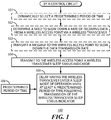
- FIG. 1 presents a process 100 that illustrates by way of example various approaches that accord with these teachings. It shall be understood that specific examples provided herein are offered by way of illustration and are not to be taken as indications of any particular limitations with respect to the scope of these teachings. In this description, and for the sake of an example, it will be presumed that a control circuit of choice carries out this process 100.
- this control circuit 201 can comprise a part of, for example, an apparatus 200 such as a so-called smart phone or tablet/pad-styled computer.
- this apparatus 200 also includes a wireless transceiver such as a wireless local area network transceiver (specifically in this example, a WLAN chipset 202) that operably couples to the control circuit 201.
- a wireless transceiver such as a wireless local area network transceiver (specifically in this example, a WLAN chipset 202) that operably couples to the control circuit 201.
- a wireless transceiver such as a wireless local area network transceiver (specifically in this example, a WLAN chipset 202) that operably couples to the control circuit 201.
- this operable coupling permits the WLAN chipset 202 to communicate received data to the control circuit 201 and/or status information regarding, for example, a present state of one or more received-data buffers as comprise a part of the WLAN chipset 202.
- this operable coupling permits the control
- the apparatus 200 can receive data via the WLAN chipset 202 as transmitted by a WLAN access point 204 via a corresponding wireless channel 205.
- this WLAN access point 204 can transmit using at least one 802.11-family protocol.
- the WLAN chipset 202 can be configured to transceive compatibly using that protocol.
- Such components are well understood in the art.
- a control circuit 201 can comprise a fixed-purpose hard-wired platform or can comprise a partially or wholly programmable platform.
- the control circuit 201 can comprise an application processor that itself comprises a System-on-a-Chip (SoC).
- SoC System-on-a-Chip
- the control circuit 201 determines a need to slow down a rate of receiving data from the wireless access point (i.e., the WLAN access point 204) via the wireless transceiver (i.e., the WLAN chipset 202).
- the control circuit 201 monitors the capacity state of one or more buffers in the WLAN chipset 202. In such a case this determination can be based upon the monitored buffer having become filled to at least a certain threshold level. As another related example, in lieu of the foregoing or in combination therewith, this determination can be based at least in part upon a rate at which the monitored buffer fills.
- the WLAN chipset 202 reports such buffer information to the control circuit 201.
- the WLAN chipset 202 may report this information unilaterally on a periodic basis and/or when and as the buffer capacity and/or rate at which the buffer fills reaches a particular reporting threshold.
- the control circuit 201 may proactively interrogate the WLAN chipset 202 to request such information.
- a data monitor component may independently and transparently monitor the flow of data into the WLAN chipset 202 and provide corresponding reports to the control circuit 201.
- this process 100 will accommodate transmitting a message to the wireless access point to slow down the data transmission rate.
- this message can comprise a Modulation coding scheme FeedBack (MFB) message as per an 802.11n-compatible standard.
- MFB Modulation coding scheme FeedBack
- This MFB message is known in the art and serves to cause a receiving wireless access point to employ a reduced rate of data transmission.
- this message can serve to cause the wireless access point to utilize smaller-sized data packets to thereby slow down the effective data throughput rate.
- this comprises using the Maximum Aggregation Media Access Control (MAC) Protocol Data Unit (A-MPDU) Length Exponent field in a Very High Throughput (VHT) capabilities element.
- a component uses this field to inform the receiver of the maximum A-MPDU length that it can receive.
- the IEEE 802.11n-2009 standard states that a sender should not transmit an A-MPDU that is longer than the value indicated by the Maximum A-MPDU Length Exponent field in the VHT Capabilities element received from the intended receiver. Decreasing the Maximum A-MPDU Length Exponent field value will force the AP to send smaller data packets to the client which will lower the throughput and hence lower the likelihood of buffer overflows at the client WLAN chipset.
- this process 100 also provides, at block 104, for transmitting to the wireless access point a wireless transceiver sleep status indicator.
- This sleep status indicator can indicate, for example, that the WLAN chipset 202 is going to sleep. Sleep refers to a low power mode for electronic devices such as computers and portable communication devices. When placed in sleep mode, the electronic device will typically cut power to unneeded subsystems and place memory into a minimum power state (typically just sufficient to retain its data).
- these teachings anticipate and will accommodate having the control circuit 201 instruct the wireless transceiver to make this transmission. In other words, these teachings will accommodate having the wireless transceiver transmit this particular message without itself having independently and unilaterally determined to enter a sleep state.
- the wireless access point i.e., the WLAN access point 204 in the present example
- the wireless transceiver will delay entering the sleep mode of operation until at least a predetermined period of time 106 following transmission of the wireless transceiver sleep status indicator.
- this predetermined period of time 106 will be sufficient to permit the wireless access point 204 to transmit and clear the aforementioned transmission buffer/queue. In some cases this predetermined period of time 106 can be static and fixed for all use cases. As one example in these regards, the predetermined period of time 106 can be at least (or no more than) 10 ms. As another example in these regards, the predetermined period of time 106 can be at least (or no more than) 30 ms.
- the control circuit can dynamically select a predetermined period of time 106. This dynamic selection may be based, for example, upon specific information that may be available to the control circuit 201 with respect to the operating parameters of the wireless access point. As another example, the control circuit 201 may maintain and access store historical records regarding the use of various predetermined periods of time to thereby develop and use, over time, a custom and dynamically-determined period of time that is particularly useful with a particular wireless access point.
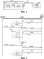
- FIG. 3 presents an illustrative example in the foregoing regards.
- a WLAN access point transmits data 301 via a wireless interface at a given throughput rate to a WLAN chipset.
- the WLAN chipset then retransmits that data 302 via a non-wireless interface at a throughput rate that is less than the throughput rate employed by the WLAN access point.
- a control circuit issues a sleep command 303 to the WLAN chipset.
- the WLAN chipset then responsively transmits a sleep status indicator 304 to the WLAN access point but itself delays 305 entering a sleep mode of operation 308. In the meantime, the WLAN access point empties its transmission queue by transmitting previously-queued data 306. Not having yet entered a sleep mode of operation 308, the WLAN chipset receives that data 306 and retransmits that data 307 via its non-wireless interface before entering the sleep mode of operation 308.
- control circuit 309 then issues an awaken command 309 to the WLAN chipset.
- the latter responsively forwards a sleep status indicator message 310 to the WLAN access point indicating its own wake status.
- the WLAN access point responds by again transmitting data 311 which the WLAN chipset again processes and retransmits 312 per its ordinary operational functionality.
- the WLAN chipset delays its own entry into a sleep mode of operation.
- Such an approach is suitable for use with a WLAN chipset having a programmable parameter in these regards.
- these teachings will accommodate having the control circuit first instruct the WLAN chipset to send the sleep status message 304 and to then transmit subsequently, following the period of predetermined delay 305, a follow-on instruction to the WLAN chipset to instruct the latter to enter the sleep mode of operation 308.
- the control circuit 201 has at least one way, and if desired a plurality of different ways, to prevent the WLAN chipset 202 from overflowing its buffers when too much data is arriving too quickly via a wireless interface as compared to the data throughput rate by which the WLAN chipset 202 can forward that data to, for example, an application processor of choice.
- these teachings can be readily deployed for use with existing chipsets and component designs without requiring redesign or reprogramming of those chipsets. Accordingly, these teachings forestall the commercial obsolescence of such components and can help contribute to economies of scale that benefit the user.
Landscapes
- Engineering & Computer Science (AREA)
- Computer Networks & Wireless Communication (AREA)
- Signal Processing (AREA)
- Mobile Radio Communication Systems (AREA)
- Small-Scale Networks (AREA)
Claims (12)
- Vorrichtung (200), die Folgendes umfasst:einen Anwendungsprozessor (201);einen drahtlosen Sendeempfänger, der über eine Datenschnittstelle funktional mit dem Anwendungsprozessor gekoppelt ist;wobei die Vorrichtung konfiguriert ist, umeinen Schlafstatusindikator des drahtlosen Sendeempfängers, der einen Schlafstatus anzeigt, welcher eine Niedrigleistungsbetriebsart der Vorrichtung umfasst, über den drahtlosen Sendeempfänger an einen drahtlosen Zugriffspunkt (204) zu übermitteln;bis mindestens für eine vorgegebene Zeitdauer nach der Übertragung des Schlafstatusindikators des drahtlosen Sendeempfängers zu verzögern, dass der drahtlose Sendeempfänger in einen Betriebsschlafmodus versetzt wird, wobei die Vorrichtung ferner konfiguriert ist, umein Erfordernis zur Verlangsamung einer Datenempfangsrate von dem drahtlosen Zugriffspunkt (204) über den drahtlosen Sendeempfänger zu ermitteln;und wobei die Vorrichtung konfiguriert ist, um den Schlafstatusindikator des drahtlosen Sendeempfängers als Reaktion auf die Ermittlung des Erfordernisses zur Verlangsamung der Datenempfangsrate von dem drahtlosen Zugriffspunkt zu übermitteln.
- Vorrichtung (200) nach Anspruch 1, wobei der drahtlose Sendeempfänger einen drahtlosen Local Area Network-Sendeempfänger umfasst.
- Vorrichtung (200) nach Anspruch 2, wobei der drahtlose Local Area Network-Sendeempfänger konfiguriert ist, um unter Verwendung von mindestens einem Protokoll der 802.11-Familie kompatibel zu senden und zu empfangen.
- Vorrichtung (200) nach Anspruch 1, wobei der Anwendungsprozessor (201) einen System-on-a-Chip, SoC, umfasst und wobei der drahtlose Sendeempfänger von dem SoC physikalisch getrennt ist.
- Vorrichtung (200) nach Anspruch 1, wobei der Schlafstatusindikator des drahtlosen Sendeempfängers anzeigt, dass der drahtlose Sendeempfänger sich in den Schlafmodus begibt.
- Vorrichtung (200) nach Anspruch 1, wobei die vorgegebene Zeitdauer mindestens 10 ms beträgt.
- Vorrichtung (200) nach Anspruch 6, wobei die vorgegebene Zeitdauer mindestens 30 ms beträgt.
- Vorrichtung (200) nach Anspruch 1, wobei die Vorrichtung ferner konfiguriert ist, um die vorgegebene Zeitdauer dynamisch auszuwählen.
- Vorrichtung (200) nach Anspruch 1,
wobei die Vorrichtung ferner konfiguriert ist, um
ebenfalls auf die Ermittlung des Erfordernisses einer Verlangsamung der Datenempfangsrate von dem drahtlosen Zugriffspunkt (204) durch Übermittlung einer Nachricht eines Modulationscodierschemafeedbacks, MFB, gemäß einem 802.11n-kompatiblen Standard an den drahtlosen Zugriffspunkt zu reagieren, um zu bewirken, dass der drahtlose Zugriffspunkt eine niedrigere Datenübertragungsrate verwendet. - Vorrichtung (200) nach Anspruch 1, wobei die Vorrichtung ferner konfiguriert ist, um ebenfalls auf die Ermittlung des Erfordernisses der Verlangsamung der Datenempfangsrate von dem drahtlosen Zugriffspunkt (204) zu reagieren, indem eine Nachricht an den drahtlosen Zugriffspunkt gesendet wird, um zu bewirken, dass der drahtlose Zugriffspunkt kleinere Datenpakete verwendet.
- Verfahren, umfassend:durch eine Steuerschaltung:Übermittlung eines Schlafstatusindikators eines drahtlosen Sendeempfängers, welcher einen Schlafstatus anzeigt, der eine Niedrigleistungsbetriebsart der Vorrichtung umfasst, über einen drahtlosen Sendeempfänger, der über eine Datenschnittstelle funktional mit einem Anwendungsprozessor (201) gekoppelt ist, an einen drahtlosen Zugriffspunkt (204);Verzögerung, dass der drahtlose Sendeempfänger in einen Betriebsschlafmodus versetzt wird, bis mindestens für eine vorgegebene Zeitdauer nach der Übertragung des Schlafstatusindikators des drahtlosen Sendeempfängers;Ermittlung eines Erfordernisses zur Verlangsamung einer Datenempfangsrate von dem drahtlosen Zugriffspunkt über den drahtlosen Sendeempfänger; undÜbermittlung des Schlafstatusindikators des drahtlosen Sendeempfängers als Reaktion auf die Ermittlung des Erfordernisses zur Verlangsamung der Datenempfangsrate von dem drahtlosen Zugriffspunkt.
- Verfahren nach Anspruch 11, das von der Vorrichtung (200) nach einem der Ansprüche 1 bis 10 implementiert wird, wobei der drahtlose Sendeempfänger einen drahtlosen Local Area Network-Sendeempfänger umfasst.
Applications Claiming Priority (1)
| Application Number | Priority Date | Filing Date | Title |
|---|---|---|---|
| US14/310,616 US9654999B2 (en) | 2014-06-20 | 2014-06-20 | Apparatus and method to reduce a rate of receiving data |
Publications (2)
| Publication Number | Publication Date |
|---|---|
| EP2958367A1 EP2958367A1 (de) | 2015-12-23 |
| EP2958367B1 true EP2958367B1 (de) | 2017-04-05 |
Family
ID=53496418
Family Applications (1)
| Application Number | Title | Priority Date | Filing Date |
|---|---|---|---|
| EP15172391.3A Active EP2958367B1 (de) | 2014-06-20 | 2015-06-16 | Vorrichtung und verfahren zur reduzierung einer datenempfangsrate |
Country Status (3)
| Country | Link |
|---|---|
| US (1) | US9654999B2 (de) |
| EP (1) | EP2958367B1 (de) |
| CA (1) | CA2894685C (de) |
Families Citing this family (8)
| Publication number | Priority date | Publication date | Assignee | Title |
|---|---|---|---|---|
| US10085211B2 (en) * | 2014-09-02 | 2018-09-25 | Apple Inc. | Communication of processor state information |
| US9622023B2 (en) * | 2014-09-23 | 2017-04-11 | Qualcomm Atheros, Inc. | Remote wakeup of sleeping subsystems |
| CN106550376B (zh) * | 2015-09-17 | 2020-06-26 | 杭州华为企业通信技术有限公司 | 一种终端唤醒方法以及装置 |
| WO2019177655A1 (en) * | 2018-03-15 | 2019-09-19 | Marvell World Trade Ltd. | Action frame to indicate change in block acknowledgment procedure |
| US10925065B2 (en) | 2018-06-15 | 2021-02-16 | Intel Corporation | Extreme high throughput physical layer data rate |
| US11350367B1 (en) | 2020-12-22 | 2022-05-31 | Qualcomm Incorporated | Adjustable leak guard for power save during wireless communications |
| WO2022139978A1 (en) * | 2020-12-22 | 2022-06-30 | Qualcomm Incorporated | Adjustable leak guard for power save during wireless communications |
| CN116636260B (zh) * | 2020-12-22 | 2024-04-16 | 高通股份有限公司 | 用于无线通信期间用于功率节省的可调整的漏泄保护的方法和装置 |
Family Cites Families (8)
| Publication number | Priority date | Publication date | Assignee | Title |
|---|---|---|---|---|
| US5109515A (en) | 1987-09-28 | 1992-04-28 | At&T Bell Laboratories | User and application program transparent resource sharing multiple computer interface architecture with kernel process level transfer of user requested services |
| US7340615B2 (en) * | 2003-01-31 | 2008-03-04 | Microsoft Corporation | Method and apparatus for managing power in network interface modules |
| US8824378B2 (en) * | 2008-02-01 | 2014-09-02 | Maarten Menzo Wentink | Unscheduled peer power save mode |
| US8498534B2 (en) | 2008-11-05 | 2013-07-30 | Broadcom Corporation | Epon with power-saving features |
| EP2277286B1 (de) | 2008-12-01 | 2016-11-23 | Marvell World Trade Ltd. | Zugangspunkterweiterungen |
| JP5573053B2 (ja) * | 2009-09-04 | 2014-08-20 | ソニー株式会社 | 無線通信装置および無線通信方法 |
| GB2493504B (en) * | 2011-07-25 | 2017-11-29 | Qualcomm Technologies Int Ltd | Data flow control |
| US9813987B2 (en) * | 2012-06-07 | 2017-11-07 | Qualcomm, Incorporated | System and method for intelligent power save notification |
-
2014
- 2014-06-20 US US14/310,616 patent/US9654999B2/en active Active
-
2015
- 2015-06-16 EP EP15172391.3A patent/EP2958367B1/de active Active
- 2015-06-19 CA CA2894685A patent/CA2894685C/en active Active
Non-Patent Citations (1)
| Title |
|---|
| None * |
Also Published As
| Publication number | Publication date |
|---|---|
| CA2894685A1 (en) | 2015-12-20 |
| US20150373575A1 (en) | 2015-12-24 |
| CA2894685C (en) | 2023-07-04 |
| EP2958367A1 (de) | 2015-12-23 |
| US9654999B2 (en) | 2017-05-16 |
Similar Documents
| Publication | Publication Date | Title |
|---|---|---|
| EP2958367B1 (de) | Vorrichtung und verfahren zur reduzierung einer datenempfangsrate | |
| EP2601765B1 (de) | Verfahren und vorrichtung zur reduzierung des overheads bei der datenübertragung | |
| US8954045B2 (en) | Method and apparatus for managing resources at a wireless device | |
| US9160662B2 (en) | Uplink buffer status reporting of relay stations in wireless networks | |
| EP2880895B1 (de) | Signalbewusste datenübertragung in mobilfunknetzen | |
| CN101960748B (zh) | 反向链路优化的信道质量估计 | |
| CN111543092B (zh) | 一种终端功率等级的调整方法及装置、计算机存储介质 | |
| CN107113733B (zh) | 用于低功率lte的子帧分配 | |
| US20090141661A1 (en) | Residual traffic state for wireless networks | |
| US8917733B2 (en) | Using wireless wide area network protocol information for managing a performance level of a processor | |
| CN105766020B (zh) | 控制传输功率和传输延迟的方法和使用其的通信终端 | |
| CN103119995A (zh) | 无线通信装置、无线通信方法以及处理电路 | |
| US10523574B2 (en) | Apparatus and method for controlling data transmission speed in wireless communication system | |
| CN112968755A (zh) | 资源配置方法、网络设备及计算机存储介质 | |
| WO2012000550A1 (en) | Method and apparatus for changing between transmission states in a communication system | |
| WO2018196407A1 (zh) | 一种资源配置方法和基站 | |
| WO2013008167A1 (en) | Packet scheduling in a cellular communication network for the purpose of device -to -device communications | |
| JP2009278532A (ja) | 送信装置及び輻輳制御方法 | |
| CN111132279A (zh) | 一种通信方法及设备 | |
| US8644241B1 (en) | Dynamic voltage-frequency management based on transmit buffer status | |
| US20250380226A1 (en) | Device to satellite power reduction | |
| WO2025255101A1 (en) | Device to satellite power reduction | |
| CN109510694A (zh) | 一种控制信道单元资源的配置方法及网络侧设备 | |
| Zieliński | Buffer Capacity Adjustment for TNC Controller | |
| CN107302502A (zh) | 终端的处理方法、装置及计算机可读存储介质 |
Legal Events
| Date | Code | Title | Description |
|---|---|---|---|
| PUAI | Public reference made under article 153(3) epc to a published international application that has entered the european phase |
Free format text: ORIGINAL CODE: 0009012 |
|
| AK | Designated contracting states |
Kind code of ref document: A1 Designated state(s): AL AT BE BG CH CY CZ DE DK EE ES FI FR GB GR HR HU IE IS IT LI LT LU LV MC MK MT NL NO PL PT RO RS SE SI SK SM TR |
|
| AX | Request for extension of the european patent |
Extension state: BA ME |
|
| RIN1 | Information on inventor provided before grant (corrected) |
Inventor name: KEZYS, VYTAUTAS ROBERTAS Inventor name: SMADI, MOHAMMED NAWAF Inventor name: BADAWY, GHADA |
|
| 17P | Request for examination filed |
Effective date: 20160616 |
|
| RBV | Designated contracting states (corrected) |
Designated state(s): AL AT BE BG CH CY CZ DE DK EE ES FI FR GB GR HR HU IE IS IT LI LT LU LV MC MK MT NL NO PL PT RO RS SE SI SK SM TR |
|
| GRAP | Despatch of communication of intention to grant a patent |
Free format text: ORIGINAL CODE: EPIDOSNIGR1 |
|
| RIC1 | Information provided on ipc code assigned before grant |
Ipc: H04W 28/12 20090101ALN20161005BHEP Ipc: H04W 28/10 20090101AFI20161005BHEP Ipc: H04W 28/02 20090101ALI20161005BHEP |
|
| INTG | Intention to grant announced |
Effective date: 20161025 |
|
| GRAS | Grant fee paid |
Free format text: ORIGINAL CODE: EPIDOSNIGR3 |
|
| GRAA | (expected) grant |
Free format text: ORIGINAL CODE: 0009210 |
|
| AK | Designated contracting states |
Kind code of ref document: B1 Designated state(s): AL AT BE BG CH CY CZ DE DK EE ES FI FR GB GR HR HU IE IS IT LI LT LU LV MC MK MT NL NO PL PT RO RS SE SI SK SM TR |
|
| REG | Reference to a national code |
Ref country code: GB Ref legal event code: FG4D |
|
| REG | Reference to a national code |
Ref country code: CH Ref legal event code: EP |
|
| REG | Reference to a national code |
Ref country code: AT Ref legal event code: REF Ref document number: 882853 Country of ref document: AT Kind code of ref document: T Effective date: 20170415 |
|
| REG | Reference to a national code |
Ref country code: IE Ref legal event code: FG4D |
|
| REG | Reference to a national code |
Ref country code: DE Ref legal event code: R096 Ref document number: 602015002101 Country of ref document: DE |
|
| REG | Reference to a national code |
Ref country code: FR Ref legal event code: PLFP Year of fee payment: 3 |
|
| REG | Reference to a national code |
Ref country code: NL Ref legal event code: FP |
|
| REG | Reference to a national code |
Ref country code: LT Ref legal event code: MG4D |
|
| REG | Reference to a national code |
Ref country code: AT Ref legal event code: MK05 Ref document number: 882853 Country of ref document: AT Kind code of ref document: T Effective date: 20170405 |
|
| PG25 | Lapsed in a contracting state [announced via postgrant information from national office to epo] |
Ref country code: ES Free format text: LAPSE BECAUSE OF FAILURE TO SUBMIT A TRANSLATION OF THE DESCRIPTION OR TO PAY THE FEE WITHIN THE PRESCRIBED TIME-LIMIT Effective date: 20170405 Ref country code: AT Free format text: LAPSE BECAUSE OF FAILURE TO SUBMIT A TRANSLATION OF THE DESCRIPTION OR TO PAY THE FEE WITHIN THE PRESCRIBED TIME-LIMIT Effective date: 20170405 Ref country code: NO Free format text: LAPSE BECAUSE OF FAILURE TO SUBMIT A TRANSLATION OF THE DESCRIPTION OR TO PAY THE FEE WITHIN THE PRESCRIBED TIME-LIMIT Effective date: 20170705 Ref country code: LT Free format text: LAPSE BECAUSE OF FAILURE TO SUBMIT A TRANSLATION OF THE DESCRIPTION OR TO PAY THE FEE WITHIN THE PRESCRIBED TIME-LIMIT Effective date: 20170405 Ref country code: HR Free format text: LAPSE BECAUSE OF FAILURE TO SUBMIT A TRANSLATION OF THE DESCRIPTION OR TO PAY THE FEE WITHIN THE PRESCRIBED TIME-LIMIT Effective date: 20170405 Ref country code: FI Free format text: LAPSE BECAUSE OF FAILURE TO SUBMIT A TRANSLATION OF THE DESCRIPTION OR TO PAY THE FEE WITHIN THE PRESCRIBED TIME-LIMIT Effective date: 20170405 Ref country code: GR Free format text: LAPSE BECAUSE OF FAILURE TO SUBMIT A TRANSLATION OF THE DESCRIPTION OR TO PAY THE FEE WITHIN THE PRESCRIBED TIME-LIMIT Effective date: 20170706 |
|
| PG25 | Lapsed in a contracting state [announced via postgrant information from national office to epo] |
Ref country code: IS Free format text: LAPSE BECAUSE OF FAILURE TO SUBMIT A TRANSLATION OF THE DESCRIPTION OR TO PAY THE FEE WITHIN THE PRESCRIBED TIME-LIMIT Effective date: 20170805 Ref country code: BG Free format text: LAPSE BECAUSE OF FAILURE TO SUBMIT A TRANSLATION OF THE DESCRIPTION OR TO PAY THE FEE WITHIN THE PRESCRIBED TIME-LIMIT Effective date: 20170705 Ref country code: SE Free format text: LAPSE BECAUSE OF FAILURE TO SUBMIT A TRANSLATION OF THE DESCRIPTION OR TO PAY THE FEE WITHIN THE PRESCRIBED TIME-LIMIT Effective date: 20170405 Ref country code: RS Free format text: LAPSE BECAUSE OF FAILURE TO SUBMIT A TRANSLATION OF THE DESCRIPTION OR TO PAY THE FEE WITHIN THE PRESCRIBED TIME-LIMIT Effective date: 20170405 Ref country code: PL Free format text: LAPSE BECAUSE OF FAILURE TO SUBMIT A TRANSLATION OF THE DESCRIPTION OR TO PAY THE FEE WITHIN THE PRESCRIBED TIME-LIMIT Effective date: 20170405 Ref country code: LV Free format text: LAPSE BECAUSE OF FAILURE TO SUBMIT A TRANSLATION OF THE DESCRIPTION OR TO PAY THE FEE WITHIN THE PRESCRIBED TIME-LIMIT Effective date: 20170405 |
|
| REG | Reference to a national code |
Ref country code: DE Ref legal event code: R097 Ref document number: 602015002101 Country of ref document: DE |
|
| PG25 | Lapsed in a contracting state [announced via postgrant information from national office to epo] |
Ref country code: CZ Free format text: LAPSE BECAUSE OF FAILURE TO SUBMIT A TRANSLATION OF THE DESCRIPTION OR TO PAY THE FEE WITHIN THE PRESCRIBED TIME-LIMIT Effective date: 20170405 Ref country code: RO Free format text: LAPSE BECAUSE OF FAILURE TO SUBMIT A TRANSLATION OF THE DESCRIPTION OR TO PAY THE FEE WITHIN THE PRESCRIBED TIME-LIMIT Effective date: 20170405 Ref country code: DK Free format text: LAPSE BECAUSE OF FAILURE TO SUBMIT A TRANSLATION OF THE DESCRIPTION OR TO PAY THE FEE WITHIN THE PRESCRIBED TIME-LIMIT Effective date: 20170405 Ref country code: MC Free format text: LAPSE BECAUSE OF FAILURE TO SUBMIT A TRANSLATION OF THE DESCRIPTION OR TO PAY THE FEE WITHIN THE PRESCRIBED TIME-LIMIT Effective date: 20170405 Ref country code: EE Free format text: LAPSE BECAUSE OF FAILURE TO SUBMIT A TRANSLATION OF THE DESCRIPTION OR TO PAY THE FEE WITHIN THE PRESCRIBED TIME-LIMIT Effective date: 20170405 Ref country code: SK Free format text: LAPSE BECAUSE OF FAILURE TO SUBMIT A TRANSLATION OF THE DESCRIPTION OR TO PAY THE FEE WITHIN THE PRESCRIBED TIME-LIMIT Effective date: 20170405 |
|
| PLBE | No opposition filed within time limit |
Free format text: ORIGINAL CODE: 0009261 |
|
| STAA | Information on the status of an ep patent application or granted ep patent |
Free format text: STATUS: NO OPPOSITION FILED WITHIN TIME LIMIT |
|
| PG25 | Lapsed in a contracting state [announced via postgrant information from national office to epo] |
Ref country code: SM Free format text: LAPSE BECAUSE OF FAILURE TO SUBMIT A TRANSLATION OF THE DESCRIPTION OR TO PAY THE FEE WITHIN THE PRESCRIBED TIME-LIMIT Effective date: 20170405 Ref country code: IT Free format text: LAPSE BECAUSE OF FAILURE TO SUBMIT A TRANSLATION OF THE DESCRIPTION OR TO PAY THE FEE WITHIN THE PRESCRIBED TIME-LIMIT Effective date: 20170405 |
|
| 26N | No opposition filed |
Effective date: 20180108 |
|
| REG | Reference to a national code |
Ref country code: IE Ref legal event code: MM4A |
|
| PG25 | Lapsed in a contracting state [announced via postgrant information from national office to epo] |
Ref country code: IE Free format text: LAPSE BECAUSE OF NON-PAYMENT OF DUE FEES Effective date: 20170616 Ref country code: LU Free format text: LAPSE BECAUSE OF NON-PAYMENT OF DUE FEES Effective date: 20170616 |
|
| REG | Reference to a national code |
Ref country code: BE Ref legal event code: MM Effective date: 20170630 |
|
| PG25 | Lapsed in a contracting state [announced via postgrant information from national office to epo] |
Ref country code: SI Free format text: LAPSE BECAUSE OF FAILURE TO SUBMIT A TRANSLATION OF THE DESCRIPTION OR TO PAY THE FEE WITHIN THE PRESCRIBED TIME-LIMIT Effective date: 20170405 |
|
| REG | Reference to a national code |
Ref country code: FR Ref legal event code: PLFP Year of fee payment: 4 |
|
| PG25 | Lapsed in a contracting state [announced via postgrant information from national office to epo] |
Ref country code: BE Free format text: LAPSE BECAUSE OF NON-PAYMENT OF DUE FEES Effective date: 20170630 |
|
| PG25 | Lapsed in a contracting state [announced via postgrant information from national office to epo] |
Ref country code: MT Free format text: LAPSE BECAUSE OF NON-PAYMENT OF DUE FEES Effective date: 20170616 |
|
| REG | Reference to a national code |
Ref country code: CH Ref legal event code: PL |
|
| PG25 | Lapsed in a contracting state [announced via postgrant information from national office to epo] |
Ref country code: CH Free format text: LAPSE BECAUSE OF NON-PAYMENT OF DUE FEES Effective date: 20180630 Ref country code: LI Free format text: LAPSE BECAUSE OF NON-PAYMENT OF DUE FEES Effective date: 20180630 |
|
| PG25 | Lapsed in a contracting state [announced via postgrant information from national office to epo] |
Ref country code: HU Free format text: LAPSE BECAUSE OF FAILURE TO SUBMIT A TRANSLATION OF THE DESCRIPTION OR TO PAY THE FEE WITHIN THE PRESCRIBED TIME-LIMIT; INVALID AB INITIO Effective date: 20150616 |
|
| PG25 | Lapsed in a contracting state [announced via postgrant information from national office to epo] |
Ref country code: CY Free format text: LAPSE BECAUSE OF FAILURE TO SUBMIT A TRANSLATION OF THE DESCRIPTION OR TO PAY THE FEE WITHIN THE PRESCRIBED TIME-LIMIT Effective date: 20170405 |
|
| PG25 | Lapsed in a contracting state [announced via postgrant information from national office to epo] |
Ref country code: MK Free format text: LAPSE BECAUSE OF FAILURE TO SUBMIT A TRANSLATION OF THE DESCRIPTION OR TO PAY THE FEE WITHIN THE PRESCRIBED TIME-LIMIT Effective date: 20170405 |
|
| PG25 | Lapsed in a contracting state [announced via postgrant information from national office to epo] |
Ref country code: TR Free format text: LAPSE BECAUSE OF FAILURE TO SUBMIT A TRANSLATION OF THE DESCRIPTION OR TO PAY THE FEE WITHIN THE PRESCRIBED TIME-LIMIT Effective date: 20170405 |
|
| PG25 | Lapsed in a contracting state [announced via postgrant information from national office to epo] |
Ref country code: PT Free format text: LAPSE BECAUSE OF FAILURE TO SUBMIT A TRANSLATION OF THE DESCRIPTION OR TO PAY THE FEE WITHIN THE PRESCRIBED TIME-LIMIT Effective date: 20170405 |
|
| PG25 | Lapsed in a contracting state [announced via postgrant information from national office to epo] |
Ref country code: AL Free format text: LAPSE BECAUSE OF FAILURE TO SUBMIT A TRANSLATION OF THE DESCRIPTION OR TO PAY THE FEE WITHIN THE PRESCRIBED TIME-LIMIT Effective date: 20170405 |
|
| REG | Reference to a national code |
Ref country code: DE Ref legal event code: R082 Ref document number: 602015002101 Country of ref document: DE Ref country code: DE Ref legal event code: R081 Ref document number: 602015002101 Country of ref document: DE Owner name: MALIKIE INNOVATIONS LTD., IE Free format text: FORMER OWNER: BLACKBERRY LIMITED, WATERLOO, ONTARIO, CA |
|
| REG | Reference to a national code |
Ref country code: GB Ref legal event code: 732E Free format text: REGISTERED BETWEEN 20240620 AND 20240627 |
|
| PGFP | Annual fee paid to national office [announced via postgrant information from national office to epo] |
Ref country code: DE Payment date: 20250626 Year of fee payment: 11 |
|
| PGFP | Annual fee paid to national office [announced via postgrant information from national office to epo] |
Ref country code: GB Payment date: 20250617 Year of fee payment: 11 |
|
| PGFP | Annual fee paid to national office [announced via postgrant information from national office to epo] |
Ref country code: NL Payment date: 20250624 Year of fee payment: 11 |
|
| PGFP | Annual fee paid to national office [announced via postgrant information from national office to epo] |
Ref country code: FR Payment date: 20250624 Year of fee payment: 11 |