EP2958364B1 - Method for reporting mbms information in wireless communication system and device for supporting same - Google Patents
Method for reporting mbms information in wireless communication system and device for supporting same Download PDFInfo
- Publication number
- EP2958364B1 EP2958364B1 EP14752166.0A EP14752166A EP2958364B1 EP 2958364 B1 EP2958364 B1 EP 2958364B1 EP 14752166 A EP14752166 A EP 14752166A EP 2958364 B1 EP2958364 B1 EP 2958364B1
- Authority
- EP
- European Patent Office
- Prior art keywords
- mbms
- information
- cell
- logging
- logged
- Prior art date
- Legal status (The legal status is an assumption and is not a legal conclusion. Google has not performed a legal analysis and makes no representation as to the accuracy of the status listed.)
- Active
Links
- 238000000034 method Methods 0.000 title claims description 102
- 238000004891 communication Methods 0.000 title claims description 17
- 238000005259 measurement Methods 0.000 claims description 235
- 230000008569 process Effects 0.000 description 24
- 230000005540 biological transmission Effects 0.000 description 22
- 238000010586 diagram Methods 0.000 description 22
- 230000011664 signaling Effects 0.000 description 19
- 230000006866 deterioration Effects 0.000 description 18
- 101001018494 Homo sapiens Pro-MCH Proteins 0.000 description 15
- 102100033721 Pro-MCH Human genes 0.000 description 15
- 238000007726 management method Methods 0.000 description 12
- 101150096310 SIB1 gene Proteins 0.000 description 10
- 230000008859 change Effects 0.000 description 8
- 230000006870 function Effects 0.000 description 8
- 239000011521 glass Substances 0.000 description 8
- 230000000737 periodic effect Effects 0.000 description 8
- 230000004044 response Effects 0.000 description 8
- 238000010187 selection method Methods 0.000 description 8
- 238000012546 transfer Methods 0.000 description 6
- 101150039363 SIB2 gene Proteins 0.000 description 5
- 230000009087 cell motility Effects 0.000 description 5
- 238000011156 evaluation Methods 0.000 description 5
- 230000033001 locomotion Effects 0.000 description 4
- 230000001960 triggered effect Effects 0.000 description 3
- 101000741965 Homo sapiens Inactive tyrosine-protein kinase PRAG1 Proteins 0.000 description 2
- 102100038659 Inactive tyrosine-protein kinase PRAG1 Human genes 0.000 description 2
- 108091005487 SCARB1 Proteins 0.000 description 2
- 102100037118 Scavenger receptor class B member 1 Human genes 0.000 description 2
- 125000004122 cyclic group Chemical group 0.000 description 2
- 238000005516 engineering process Methods 0.000 description 2
- 230000006872 improvement Effects 0.000 description 2
- 230000007774 longterm Effects 0.000 description 2
- 238000012544 monitoring process Methods 0.000 description 2
- 238000013468 resource allocation Methods 0.000 description 2
- 230000002123 temporal effect Effects 0.000 description 2
- 101100150273 Caenorhabditis elegans srb-1 gene Proteins 0.000 description 1
- 241000700159 Rattus Species 0.000 description 1
- 230000008901 benefit Effects 0.000 description 1
- 238000012508 change request Methods 0.000 description 1
- 230000006835 compression Effects 0.000 description 1
- 238000007906 compression Methods 0.000 description 1
- 238000012937 correction Methods 0.000 description 1
- 230000001419 dependent effect Effects 0.000 description 1
- 238000012854 evaluation process Methods 0.000 description 1
- 238000001914 filtration Methods 0.000 description 1
- 230000001788 irregular Effects 0.000 description 1
- 238000013507 mapping Methods 0.000 description 1
- 230000007246 mechanism Effects 0.000 description 1
- 238000010295 mobile communication Methods 0.000 description 1
- 238000011017 operating method Methods 0.000 description 1
- 238000012545 processing Methods 0.000 description 1
- 230000011218 segmentation Effects 0.000 description 1
- 230000008054 signal transmission Effects 0.000 description 1
- 238000012360 testing method Methods 0.000 description 1
Images


Classifications
-
- H—ELECTRICITY
- H04—ELECTRIC COMMUNICATION TECHNIQUE
- H04W—WIRELESS COMMUNICATION NETWORKS
- H04W4/00—Services specially adapted for wireless communication networks; Facilities therefor
- H04W4/06—Selective distribution of broadcast services, e.g. multimedia broadcast multicast service [MBMS]; Services to user groups; One-way selective calling services
-
- H—ELECTRICITY
- H04—ELECTRIC COMMUNICATION TECHNIQUE
- H04L—TRANSMISSION OF DIGITAL INFORMATION, e.g. TELEGRAPHIC COMMUNICATION
- H04L12/00—Data switching networks
- H04L12/02—Details
- H04L12/16—Arrangements for providing special services to substations
- H04L12/18—Arrangements for providing special services to substations for broadcast or conference, e.g. multicast
- H04L12/189—Arrangements for providing special services to substations for broadcast or conference, e.g. multicast in combination with wireless systems
-
- H—ELECTRICITY
- H04—ELECTRIC COMMUNICATION TECHNIQUE
- H04L—TRANSMISSION OF DIGITAL INFORMATION, e.g. TELEGRAPHIC COMMUNICATION
- H04L47/00—Traffic control in data switching networks
- H04L47/10—Flow control; Congestion control
- H04L47/12—Avoiding congestion; Recovering from congestion
-
- H—ELECTRICITY
- H04—ELECTRIC COMMUNICATION TECHNIQUE
- H04W—WIRELESS COMMUNICATION NETWORKS
- H04W24/00—Supervisory, monitoring or testing arrangements
- H04W24/02—Arrangements for optimising operational condition
-
- H—ELECTRICITY
- H04—ELECTRIC COMMUNICATION TECHNIQUE
- H04W—WIRELESS COMMUNICATION NETWORKS
- H04W24/00—Supervisory, monitoring or testing arrangements
- H04W24/08—Testing, supervising or monitoring using real traffic
-
- H—ELECTRICITY
- H04—ELECTRIC COMMUNICATION TECHNIQUE
- H04W—WIRELESS COMMUNICATION NETWORKS
- H04W36/00—Hand-off or reselection arrangements
- H04W36/0005—Control or signalling for completing the hand-off
- H04W36/0055—Transmission or use of information for re-establishing the radio link
- H04W36/0058—Transmission of hand-off measurement information, e.g. measurement reports
-
- H—ELECTRICITY
- H04—ELECTRIC COMMUNICATION TECHNIQUE
- H04W—WIRELESS COMMUNICATION NETWORKS
- H04W36/00—Hand-off or reselection arrangements
- H04W36/0005—Control or signalling for completing the hand-off
- H04W36/0083—Determination of parameters used for hand-off, e.g. generation or modification of neighbour cell lists
- H04W36/0085—Hand-off measurements
-
- H—ELECTRICITY
- H04—ELECTRIC COMMUNICATION TECHNIQUE
- H04W—WIRELESS COMMUNICATION NETWORKS
- H04W72/00—Local resource management
- H04W72/30—Resource management for broadcast services
-
- H—ELECTRICITY
- H04—ELECTRIC COMMUNICATION TECHNIQUE
- H04W—WIRELESS COMMUNICATION NETWORKS
- H04W36/00—Hand-off or reselection arrangements
- H04W36/0005—Control or signalling for completing the hand-off
- H04W36/0055—Transmission or use of information for re-establishing the radio link
-
- H—ELECTRICITY
- H04—ELECTRIC COMMUNICATION TECHNIQUE
- H04W—WIRELESS COMMUNICATION NETWORKS
- H04W88/00—Devices specially adapted for wireless communication networks, e.g. terminals, base stations or access point devices
- H04W88/02—Terminal devices
Definitions
- the present invention relates to wireless communication and, more particularly, to a method for reporting Multimedia Broadcast and Multicast Service (MBMS) information in a wireless communication system and a device supporting the same.
- MBMS Multimedia Broadcast and Multicast Service
- 3rd generation partnership project (3GPP) long term evolution (LTE) is an improved version of a universal mobile telecommunication system (UMTS) and is introduced as the 3GPP release 8.
- the 3GPP LTE uses orthogonal frequency division multiple access (OFDMA) in a downlink, and uses single carrier-frequency division multiple access (SC-FDMA) in an uplink.
- OFDMA orthogonal frequency division multiple access
- SC-FDMA single carrier-frequency division multiple access
- MIMO multiple input multiple output
- LTE-A 3GPP LTE-advanced
- US 2013/0010624 A1 describes a method and system for measuring and reporting a multimedia broadcast multicast service (MBMS).
- MBMS multimedia broadcast multicast service
- a user equipment (UE) measures the MBMS according to a measurement configuration, and when a measurement reporting norm is met, the UE reports a measurement result or a measurement log of the measured MBMS measurement quantity to a network side.
- UE user equipment
- a logged measurements configuration info may contain a parameter of choice area configuration for indicating an area for which a user equipment is requested to perform logging.
- a Multimedia Broadcast and Multicast Service is one of those services, and provides a terminal with information that may be provided in TV, movie, and digital forms in a broadcast and/or multicast manner.
- the MBMS has a great advantage in excellent efficiency compared to the case where a network is newly constructed in order to provide a service in that it can provide a service through the infrastructure of an already constructed network.
- a network obtains a measured result from a terminal.
- the network may also obtain location information related to the measured result from the terminal and optimize network performance more efficiently.
- service providers may obtain a measured result and location information using a terminal, which is called a Minimization of Driving Test (MDT).
- MDT Minimization of Driving Test
- a network may support an MBMS MDT.
- the MBMS MDT may include a series of procedures, such as a configuration, acquisition, and reporting for MBMS information reporting.
- the network may select a terminal for the MBMS information reporting based on the capabilities of a terminal and/or the consent of a terminal user.
- an MBMS service is provided on an MBMS Single Frequency Network (MBSFN) area through broadcast or multicast, and a terminal that receives the MBMS service does not provide corresponding feedback. Accordingly, a network rarely obtains information about the MBMS reception status of the terminal. Accordingly, there is a need for a method that enables a network to receive a report on MBMS information from a terminal.
- MMSFN MBMS Single Frequency Network
- An object of the present invention is to provide a method for performing Multimedia Broadcast and Multicast Service (MBMS) related measurements in a wireless communication system and a device supporting the same.
- MBMS Multimedia Broadcast and Multicast Service
- a network can set an MBMS information acquisition/logging scope for the report of MBMS information in UE so that the UE can log MBMS information and report the logged MBMS information only when the logging scope is satisfied. Accordingly, the measurements of an MBMS service and the reporting of MBMS information by UE can be controlled. This enables control of power consumed for the reporting of MBMS information by UE and enables control of signaling for the reporting of MBMS information. As a result, efficient power management and efficient management of radio resources for UE can be possible.
- FIG. 1 shows a wireless communication system to which the present invention is applied.
- the wireless communication system may also be referred to as an evolved-UMTS terrestrial radio access network (E-UTRAN) or a long term evolution (LTE)/LTE-A system.
- E-UTRAN evolved-UMTS terrestrial radio access network
- LTE long term evolution
- LTE-A long term evolution
- the E-UTRAN includes at least one base station (BS) 20 which provides a control plane and a user plane to a user equipment (UE) 10.
- the UE 10 may be fixed or mobile, and may be referred to as another terminology, such as a mobile station (MS), a user terminal (UT), a subscriber station (SS), a mobile terminal (MT), a wireless device, etc.
- the BS 20 is generally a fixed station that communicates with the UE 10 and may be referred to as another terminology, such as an evolved node-B (eNB), a base transceiver system (BTS), an access point, etc.
- eNB evolved node-B
- BTS base transceiver system
- access point etc.
- the BSs 20 are interconnected by means of an X2 interface.
- the BSs 20 are also connected by means of an S1 interface to an evolved packet core (EPC) 30, more specifically, to a mobility management entity (MME) through S1-MME and to a serving gateway (S-GW) through S1-U.
- EPC evolved packet core
- MME mobility management entity
- S-GW serving gateway
- the EPC 30 includes an MME, an S-GW, and a packet data network-gateway (P-GW).
- the MME has access information of the UE or capability information of the UE, and such information is generally used for mobility management of the UE.
- the S-GW is a gateway having an E-UTRAN as an end point.
- the P-GW is a gateway having a PDN as an end point.
- Layers of a radio interface protocol between the UE and the network can be classified into a first layer (LI), a second layer (L2), and a third layer (L3) based on the lower three layers of the open system interconnection (OSI) model that is well-known in the communication system.
- LI first layer
- L2 second layer
- L3 third layer
- OSI open system interconnection
- a physical (PHY) layer belonging to the first layer provides an information transfer service by using a physical channel
- RRC radio resource control
- the RRC layer exchanges an RRC message between the UE and the BS.
- FIG. 2 is a diagram showing a wireless protocol architecture for a user plane.
- FIG. 3 is a diagram showing a wireless protocol architecture for a control plane.
- the user plane is a protocol stack for user data transmission.
- the control plane is a protocol stack for control signal transmission.
- a PHY layer provides an upper layer with an information transfer service through a physical channel.
- the PHY layer is connected to a medium access control (MAC) layer which is an upper layer of the PHY layer through a transport channel.
- MAC medium access control
- Data is transferred between the MAC layer and the PHY layer through the transport channel.
- the transport channel is classified according to how and with what characteristics data is transferred through a radio interface.
- the physical channel may be modulated according to an Orthogonal Frequency Division Multiplexing (OFDM) scheme, and use the time and frequency as radio resources.
- OFDM Orthogonal Frequency Division Multiplexing
- the functions of the MAC layer include mapping between a logical channel and a transport channel and multiplexing and demultiplexing to a transport block that is provided through a physical channel on the transport channel of a MAC Service Data Unit (SDU) that belongs to a logical channel.
- SDU MAC Service Data Unit
- the MAC layer provides service to a Radio Link Control (RLC) layer through the logical channel.
- RLC Radio Link Control
- the functions of the RLC layer include the concatenation, segmentation, and reassembly of an RLC SDU.
- QoS Quality of Service
- RB Radio Bearer
- the RLC layer provides three types of operation mode: Transparent Mode (TM), Unacknowledged Mode (UM), and Acknowledged Mode (AM).
- TM Transparent Mode
- UM Unacknowledged Mode
- AM Acknowledged Mode
- AM RLC provides error correction through an Automatic Repeat Request (ARQ).
- ARQ Automatic Repeat Request
- the RRC layer is defined only on the control plane.
- the RRC layer is related to the configuration, reconfiguration, and release of radio bearers, and is responsible for control of logical channels, transport channels, and PHY channels.
- An RB means a logical route that is provided by the first layer (PHY layer) and the second layers (MAC layer, the RLC layer, and the PDCP layer) in order to transfer data between UE and a network.
- the function of a Packet Data Convergence Protocol (PDCP) layer on the user plane includes the transfer of user data and header compression and ciphering.
- the function of the PDCP layer on the user plane further includes the transfer and encryption/integrity protection of control plane data.
- PDCP Packet Data Convergence Protocol
- What an RB is configured means a process of defining the characteristics of a wireless protocol layer and channels in order to provide specific service and configuring each detailed parameter and operating method.
- An RB can be divided into two types of a Signaling RB (SRB) and a Data RB (DRB).
- SRB Signaling RB
- DRB Data RB
- the SRB is used as a passage through which an RRC message is transmitted on the control plane
- the DRB is used as a passage through which user data is transmitted on the user plane.
- the UE If RRC connection is established between the RRC layer of UE and the RRC layer of an E-UTRAN, the UE is in the RRC connected state. If not, the UE is in the RRC idle state.
- a downlink transport channel through which data is transmitted from a network to UE includes a broadcast channel (BCH) through which system information is transmitted and a downlink shared channel (SCH) through which user traffic or control messages are transmitted. Traffic or a control message for downlink multicast or broadcast service may be transmitted through the downlink SCH, or may be transmitted through an additional downlink multicast channel (MCH).
- BCH broadcast channel
- SCH downlink shared channel
- Traffic or a control message for downlink multicast or broadcast service may be transmitted through the downlink SCH, or may be transmitted through an additional downlink multicast channel (MCH).
- MCH downlink multicast channel
- an uplink transport channel through which data is transmitted from UE to a network includes a random access channel (RACH) through which an initial control message is transmitted and an uplink shared channel (SCH) through which user traffic or control messages are transmitted.
- RACH random access channel
- SCH uplink shared channel
- Logical channels that are placed over the transport channel and that are mapped to the transport channel include a broadcast control channel (BCCH), a paging control channel (PCCH), a common control channel (CCCH), a multicast control channel (MCCH), and a multicast traffic channel (MTCH).
- BCCH broadcast control channel
- PCCH paging control channel
- CCCH common control channel
- MCCH multicast control channel
- MTCH multicast traffic channel
- the physical channel includes several OFDM symbols in the time domain and several subcarriers in the frequency domain.
- One subframe includes a plurality of OFDM symbols in the time domain.
- An RB is a resources allocation unit, and includes a plurality of OFDM symbols and a plurality of subcarriers.
- each subframe may use specific subcarriers of specific OFDM symbols (e.g., the first OFDM symbol) of the corresponding subframe for a physical downlink control channel (PDCCH), that is, an L1/L2 control channel.
- PDCCH physical downlink control channel
- a Transmission Time Interval (TTI) is a unit time for subframe transmission.
- a physical channel in a 3GPP LTE may be divided into a PDSCH (Physical Downlink Shared Channel) and a PUSCH (Physical Uplink Shared Channel) being a data channel and a PDCCH (Physical Downlink Control Channel), a PCFICH (Physical Control Format Indicator Channel), a PHICH (Physical Hybrid-ARQ Indicator Channel), and a PUCCH (Physical Uplink Control Channel) being a control channel.
- PDSCH Physical Downlink Shared Channel
- PUSCH Physical Uplink Shared Channel
- PDCCH Physical Downlink Control Channel
- PCFICH Physical Control Format Indicator Channel
- PHICH Physical Hybrid-ARQ Indicator Channel
- PUCCH Physical Uplink Control Channel
- a PCFICH transmitted through a first OFDM symbol of a sub-frame carries a CFI (control format indicator) with respect to the number of OFDM symbols used to transmit control channels in a sub-frame.
- the terminal firstly receives a CFI on a PCFICH to monitor the PDCCH.
- the PDCCH refers to a scheduling channel to carry schedule information as a downlink control channel.
- the control information transmitted through the PDCCH refers to downlink control information (DCI).
- the DCI may include resource allocation of the PDSCH (refers to DL grant (downlink grant)), resource allocation of the PUSCH (refers to uplink (UL) grant)), and a group and/or VoIP (Voice over Internet Protocol) of a transmission power control command with respect to individual UEs in an optional UE group.
- blind decoding is used to detect the PDCCH.
- the blind decoding de-masks a desired identifier to a CRC (Cyclic Redundancy Check) of a received PDCCH (refers to candidate PDCCH), and checks a CRC error to determine whether a corresponding PDCCH is a control channel thereof.
- CRC Cyclic Redundancy Check
- the base station determines a PDCCH format according to a DCI to be sent to the terminal to attach a CRC to the DCI, and masks a unique identifier (refers to RNTI (Radio Network Temporary Identifier)) according to an owner or a use of the PDCCH.
- RNTI Radio Network Temporary Identifier
- the RRC state of UE and an RRC connection method are described below.
- the RRC state means whether or not the RRC layer of UE is logically connected to the RRC layer of the E-UTRAN.
- a case where the RRC layer of UE is logically connected to the RRC layer of the E-UTRAN is referred to as an RRC connected state.
- a case where the RRC layer of UE is not logically connected to the RRC layer of the E-UTRAN is referred to as an RRC idle state.
- the E-UTRAN may check the existence of corresponding UE in the RRC connected state in each cell because the UE has RRC connection, so the UE may be effectively controlled.
- the E-UTRAN is unable to check UE in the RRC idle state, and a Core Network (CN) manages UE in the RRC idle state in each tracking area, that is, the unit of an area greater than a cell. That is, the existence or non-existence of UE in the RRC idle state is checked only for each large area. Accordingly, the UE needs to shift to the RRC connected state in order to be provided with common mobile communication service, such as voice or data.
- CN Core Network
- the UE When a user first powers UE, the UE first searches for a proper cell and remains in the RRC idle state in the corresponding cell.
- the UE in the RRC idle state establishes RRC connection with an E-UTRAN through an RRC connection procedure when it is necessary to set up the RRC connection, and shifts to the RRC connected state.
- a case where UE in the RRC idle state needs to set up RRC connection includes several cases.
- the cases may include a need to send uplink data for a reason, such as a call attempt by a user, and to send a response message as a response to a paging message received from an E-UTRAN.
- a Non-Access Stratum (NAS) layer placed over the RRC layer performs functions, such as session management and mobility management.
- functions such as session management and mobility management.
- EMM-REGISTERED EPS Mobility Management-REGISTERED
- EMM-DEREGISTERED EMM-DEREGISTERED
- the two states are applied to UE and the MME.
- UE is initially in the EMM-DEREGISTERED state.
- the UE performs a process of registering it with the corresponding network through an initial attach procedure. If the attach procedure is successfully performed, the UE and the MME become the EMM-REGISTERED state.
- an EPS Connection Management (ECM)-IDLE state In order to manage signaling connection between UE and the EPC, two types of states: an EPS Connection Management (ECM)-IDLE state and an ECM-CONNECTED state are defined.
- the two states are applied to UE and the MME.
- ECM-IDLE state When the UE in the ECM-IDLE state establishes RRC connection with the E-UTRAN, the UE becomes the ECM-CONNECTED state.
- the MME in the ECM-IDLE state becomes the ECM-CONNECTED state when it establishes S1 connection with the E-UTRAN.
- the E-UTRAN does not have information about the context of the UE.
- the UE in the ECM-IDLE state performs procedures related to UE-based mobility, such as cell selection or cell reselection, without a need to receive a command from a network.
- the mobility of the UE is managed in response to a command from a network. If the location of the UE in the ECM-IDLE state is different from a location known to the network, the UE informs the network of its corresponding location through a tracking area update procedure.
- System information includes essential information that needs to be known by UE in order for the UE to access a BS. Accordingly, the UE needs to have received all pieces of system information before accessing the BS, and needs to always have the up-to-date system information. Furthermore, the BS periodically transmits the system information because the system information is information that needs to be known by all UEs within one cell.
- the system information is divided into a MIB (Master Information Block) and a plurality of SIBs (System Information Blocks).
- the MIB may include a limited number of parameters which are most frequently transmitted and are required for acquisition for other information from a cell.
- the terminal firstly searches the MIB after downlink synchronization.
- the MIB may include information such as a downlink channel bandwidth, PHICH configuration, an SFN to support synchronization and to be operated as a timing reference, and eNB transmission antenna configuration.
- the MIB may be broadcasted on the BCH.
- a SIB1 (SystemInformationBlockType1) among SIBs is transmitted while being included in a SystemInformationBlockType1", and other SIBs except for the SIB1 is transmitted while being included in the system information message.
- the SIBs may be flexibly mapped to the system information message according to a scheduling information list parameter included in the SIB1. However, each SIB is included in a single system information message, and only SIBs having the same scheduling required value (e.g. period) may be mapped to the same system information message. Further, a SIB2 (SystemInformationBlockType2) is mapped to a system information message corresponding to a first entry in a system information message list of a scheduling information list. A plurality of system information messages may be transmitted within the same time period. The SIB1 and all system information messages are transmitted on a DL-SCH.
- the E-UTRAN may be dedicated- signaled in a state that the SIB1 includes the same parameter as a preconfiguration value.
- the SIB1 may be transmitted while being included in a RRC connection reconfiguration message.
- the SIB1 includes information on terminal cell access, and defines scheduling of other SIBs.
- the SIB1 may include PLMN identifiers of a network, a TAC (Tracking Area Code), a cell ID, a cell barring status to indicate whether a cell may camp-on, the lowest reception level required in a cell used as a cell reselection reference, and information on a transmission time and a time period of other SIBs.
- the SIB2 may include radio resource configuration information common in all terminals.
- the SIB2 may include a uplink carrier frequency, an uplink channel bandwidth, RACH configuration, paging configuration, uplink power control configuration, sounding reference signal configuration, ACK/NACK PUCCH configuration and PUSCH configuration supporting ACK/NACK transmission.
- the terminal may apply acquisition and change sensing procedures of system information with respect to only a PCell.
- the E-UTRAN may provide all system information on the RRC connection state operation through dedicated signaling when a corresponding SCell is added.
- the E-UTRAN may release a considered SCell and may add the considered SCell later, which may be performed together with a single RRC connection reconfiguration message.
- the E-UTRAN may configure parameter values different from a value broadcasted in the considered SCell through the dedicated signaling.
- the terminal should ensure validity with respect to system information of a specific type.
- the above system information refers to required system information.
- the required system information may be defined as follows.
- service that is provided to UE by a network may be classified into three types as follows. Furthermore, the UE differently recognizes the type of cell depending on what service may be provided to the UE. In the following description, a service type is first described, and the type of cell is described.
- the type of cell may be classified as follows.
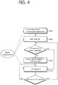
- FIG. 4 is a flowchart illustrating the operation of UE in the RRC idle state.
- FIG. 4 illustrates a procedure in which UE that is initially powered on experiences a cell selection process, registers it with a network, and then performs cell reselection if necessary.
- the UE selects Radio Access Technology (RAT) in which the UE communicates with a Public Land Mobile Network (PLMN), that is, a network from which the UE is provided with service (S410).
- RAT Radio Access Technology
- PLMN Public Land Mobile Network
- S410 a network from which the UE is provided with service
- Information about the PLMN and the RAT may be selected by the user of the UE, and the information stored in a Universal Subscriber Identity Module (USIM) may be used.
- USIM Universal Subscriber Identity Module
- the UE selects a cell that has the greatest value and that belongs to cells having measured BS and signal intensity or quality greater than a specific value (cell selection) (S420).
- cell selection a specific value
- the UE that is powered off performs cell selection, which may be called initial cell selection.
- a cell selection procedure is described later in detail.
- the UE receives system information periodically by the BS.
- the specific value refers to a value that is defined in a system in order for the quality of a physical signal in data transmission/reception to be guaranteed. Accordingly, the specific value may differ depending on applied RAT.
- the UE performs a network registration procedure (S430).
- the UE registers its information (e.g., an IMSI) with the network in order to receive service (e.g., paging) from the network.
- the UE does not register it with a network whenever it selects a cell, but registers it with a network when information about the network (e.g., a Tracking Area Identity (TAI)) included in system information is different from information about the network that is known to the UE.
- TAI Tracking Area Identity
- the UE performs cell reselection based on a service environment provided by the cell or the environment of the UE (S440). If the value of the intensity or quality of a signal measured based on a BS from which the UE is provided with service is lower than that measured based on a BS of a neighboring cell, the UE selects a cell that belongs to other cells and that provides better signal characteristics than the cell of the BS that is accessed by the UE. This process is called cell reselection differently from the initial cell selection of the No. 2 process. In this case, temporal restriction conditions are placed in order for a cell to be frequently reselected in response to a change of signal characteristic. A cell reselection procedure is described later in detail.
- FIG. 5 is a flowchart illustrating a process of establishing RRC connection.
- the UE sends an RRC connection request message that requests RRC connection to a network (S510).
- the network sends an RRC connection establishment message as a response to the RRC connection request (S520). After receiving the RRC connection establishment message, the UE enters RRC connected mode.
- the UE sends an RRC connection establishment complete message used to check the successful completion of the RRC connection to the network (S530).
- FIG. 6 is a flowchart illustrating an RRC connection reconfiguration process.
- An RRC connection reconfiguration is used to modify RRC connection. This is used to establish/modify/release RBs, perform handover, and set up/modify/release measurements.
- a network sends an RRC connection reconfiguration message for modifying RRC connection to UE (S610).
- the UE sends an RRC connection reconfiguration complete message used to check the successful completion of the RRC connection reconfiguration to the network (S620).
- PLMN public land mobile network
- the PLMN is a network which is disposed and operated by a mobile network operator. Each mobile network operator operates one or more PLMNs. Each PLMN may be identified by a Mobile Country Code (MCC) and a Mobile Network Code (MNC). PLMN information of a cell is included in system information and broadcasted.
- MCC Mobile Country Code
- MNC Mobile Network Code
- PLMN selection In PLMN selection, cell selection, and cell reselection, various types of PLMNs may be considered by the terminal.
- HPLMN Home PLMN
- MCC and MNC matching with MCC and MNC of a terminal IMSI.
- Equivalent HPLMN PLMN serving as an equivalent of an HPLMN.
- Registered PLMN PLMN successfully finishing location registration.
- ELMN Equivalent PLMN
- Each mobile service consumer subscribes in the HPLMN.
- a general service is provided to the terminal through the HPLMN or the EHPLMN, the terminal is not in a roaming state.
- the service is provided to the terminal through a PLMN except for the HPLMN/EHPLMN, the terminal is in the roaming state.
- the PLMN refers to a Visited PLMN (VPLMN).
- the PLMN is a network that is deployed or operated by a mobile network operator. Each mobile network operator operates one or more PLMNs. Each PLMN may be identified by Mobile Country Code (MCC) and Mobile Network Code (MNC). Information about the PLMN of a cell is included in system information and broadcasted. The UE attempts to register it with the selected PLMN. If registration is successful, the selected PLMN becomes a Registered PLMN (RPLMN). The network may signalize a PLMN list to the UE.
- MCC Mobile Country Code
- MNC Mobile Network Code
- PLMNs included in the PLMN list may be considered to be PLMNs, such as RPLMNs.
- the UE registered with the network needs to be able to be always reachable by the network. If the UE is in the ECM-CONNECTED state (identically the RRC connection state), the network recognizes that the UE is being provided with service. If the UE is in the ECM-IDLE state (identically the RRC idle state), however, the situation of the UE is not valid in an eNB, but is stored in the MME. In such a case, only the MME is informed of the location of the UE in the ECM-IDLE state through the granularity of the list of Tracking Areas (TAs).
- a single TA is identified by a Tracking Area Identity (TAI) formed of the identifier of a PLMN to which the TA belongs and Tracking Area Code (TAC) that uniquely expresses the TA within the PLMN.
- TAI Tracking Area Identity
- the UE selects a cell that belongs to cells provided by the selected PLMN and that has signal quality and characteristics on which the UE is able to be provided with proper service.
- the terminal When power is turned-on or the terminal is located in a cell, the terminal performs procedures for receiving a service by selecting/reselecting a suitable quality cell.
- a terminal in an RRC idle state should prepare to receive a service through the cell by always selecting a suitable quality cell. For example, a terminal where power is turned-on just before should select the suitable quality cell to be registered in a network. If the terminal in an RRC connection state enters in an RRC idle state, the terminal should selects a cell for stay in the RRC idle state. In this way, a procedure of selecting a cell satisfying a certain condition by the terminal in order to be in a service idle state such as the RRC idle state refers to cell selection. Since the cell selection is performed in a state that a cell in the RRC idle state is not currently determined, it is important to select the cell as rapid as possible. Accordingly, if the cell provides a wireless signal quality of a predetermined level or greater, although the cell does not provide the best wireless signal quality, the cell may be selected during a cell selection procedure of the terminal.
- a method and a procedure of selecting a cell by a terminal in a 3GPP LTE is described with reference to 3GPP TS 36.304 V8.5.0 (2009-03) "User Equipment (UE) procedures in idle mode (Release 8)".
- UE User Equipment
- a cell selection process is basically divided into two types.
- the first is an initial cell selection process.
- UE does not have preliminary information about a wireless channel. Accordingly, the UE searches for all wireless channels in order to find out a proper cell. The UE searches for the strongest cell in each channel. Thereafter, if the UE has only to search for a suitable cell that satisfies a cell selection criterion, the UE selects the corresponding cell.
- the UE may select the cell using stored information or using information broadcasted by the cell. Accordingly, cell selection may be fast compared to an initial cell selection process. If the UE has only to search for a cell that satisfies the cell selection criterion, the UE selects the corresponding cell. If a suitable cell that satisfies the cell selection criterion is not retrieved though such a process, the UE performs an initial cell selection process.
- a cell selection reference may be defined as expressed by a following equation 1.
- respective variables of the equation 1 may be defined by a following table 1.
- Table 1 Srxlev Cell selection RX level value (dB) Squal Cell selection quality value (dB) Q rxlevmeas Measured cell RX level value (RSRP) Q qualmeas Measured cell quality value (RSRQ) Q rxlevmin Minimum required RX level in the cell (dBm) Q qualmin Minimum required quality level in the cell (dB) Q rxlevminoffset Offset to the signalled Q rxlevmin taken into account in the Srxlev evaluation as a result of a periodic search for a higher priority PLMN while camped normally in a VPLMN [5] Q qualminoffset Offset to the signalled Q qualmin taken into account in the Squal evaluation as a result of a periodic search for a higher priority PLMN while camped normally in a VPLMN [5] Pcompensation max(P EMAX -P PowerClass , 0) (dB) (d
- Signaled values Qrxlevminoffset and Qqualminoffset are a result of periodic search with respect to a PLMN of a higher priority while the terminal camps on a normal cell in the VPLMN.
- the terminal may perform cell selection estimation using stored parameters from other cell of the PLMN having the higher priority.
- the intensity or quality of a signal between the UE and a BS may be changed due to a change in the mobility or wireless environment of the UE. Accordingly, if the quality of the selected cell is deteriorated, the UE may select another cell that provides better quality. If a cell is reselected as described above, the UE selects a cell that provides better signal quality than the currently selected cell. Such a process is called cell reselection. In general, a basic object of the cell reselection process is to select a cell that provides UE with the best quality from a viewpoint of the quality of a radio signal.
- a network may determine priority corresponding to each frequency, and may inform the UE of the determined priorities.
- the UE that has received the priorities preferentially takes into consideration the priorities in a cell reselection process compared to a radio signal quality criterion.
- the following cell reselection methods may be present according to the RAT and frequency characteristics of the cell.
- UE measures the quality of a serving cell and neighbor cells for cell reselection.
- cell reselection is performed based on a cell reselection criterion.
- the cell reselection criterion has the following characteristics in relation to the measurements of a serving cell and neighbor cells.
- Intra-frequency cell reselection is basically based on ranking.
- Ranking is a task for defining a criterion value for evaluating cell reselection and numbering cells using criterion values according to the size of the criterion values.
- a cell having the best criterion is commonly called the best-ranked cell.
- the cell criterion value is based on the value of a corresponding cell measured by UE, and may be a value to which a frequency offset or cell offset has been applied, if necessary.
- Inter-frequency cell reselection is based on frequency priority provided by a network.
- UE attempts to camp on a frequency having the highest frequency priority.
- a network may provide frequency priority that will be applied by UEs within a cell in common through broadcasting signaling, or may provide frequency-specific priority to each UE through UE-dedicated signaling.
- a cell reselection priority provided through broadcast signaling may refer to a common priority.
- a cell reselection priority for each terminal set by a network may refer to a dedicated priority. If receiving the dedicated priority, the terminal may receive a valid time associated with the dedicated priority together. If receiving the dedicated priority, the terminal starts a validity timer set as the received valid time together therewith. While the valid timer is operated, the terminal applies the dedicated priority in the RRC idle mode. If the valid timer is expired, the terminal discards the dedicated priority and again applies the common priority.
- a network may provide UE with a parameter (e.g., a frequency-specific offset) used in cell reselection for each frequency.
- a parameter e.g., a frequency-specific offset
- a network may provide UE with a Neighboring Cell List (NCL) used in cell reselection.
- NCL Neighboring Cell List
- the NCL includes a cell-specific parameter (e.g., a cell-specific offset) used in cell reselection.
- a network may provide UE with a cell reselection black list used in cell reselection. The UE does not perform cell reselection on a cell included in the black list.
- a ranking criterion used to apply priority to a cell is defined as in Equation 1.
- R s Q meas , s + Q hyst
- R n Q meas , s ⁇ Q offset
- R s is the ranking criterion of a serving cell
- R n is the ranking criterion of a neighbor cell
- Q meas,s is the quality value of the serving cell measured by UE
- Q meas,n is the quality value of the neighbor cell measured by UE
- Q hyst is the hysteresis value for ranking
- Q offset is an offset between the two cells.
- ranking priority is frequency changed as a result of the change, and UE may alternately reselect the twos.
- Q hyst is a parameter that gives hysteresis to cell reselection so that UE is prevented from to alternately reselecting two cells.
- UE measures R S of a serving cell and R n of a neighbor cell according to the above equation, considers a cell having the greatest ranking criterion value to be the highest-ranked cell, and reselects the cell.
- UE may be checked that the quality of a cell is the most important criterion in cell reselection. If a reselected cell is not a suitable cell, UE excludes a corresponding frequency or a corresponding cell from the subject of cell reselection.
- the terminal determines that the cell reselection reference is satisfied and may perform cell movement to a selected target cell.
- the specific time may be given from the network as a Treselection parameter.
- the Treselection may specify a cell reselection timer value, and may be defined with respect to each frequency of the E-UTRAN and other RAT.
- the cell reselection information is a type of a cell reselection parameter and may be transmitted and provided to the terminal while being included in the system information broadcasted from the network.
- the cell reselection parameter provided to the terminal may include following types.
- the cellReselectionPriority parameter specifies a priority with respect to a frequency of the E-UTRAN, a frequency of a UTRAN, a group of GERAN frequencies, a band glass of a CDMA2000 HRPD or a band glass of a CDMA2000 1xRTT.
- Qoffset s,n specifies an offset value between two cells.
- Qoffset frequency specifies frequency specific offset with respect to an E-UTRAN frequency having the same priority.
- Q hyst specifies a hysteresis value with respect a rank index.
- Q qualmin specifies a required minimum quality level in a dB unit.
- Q rxlevmin specifies a required minimum Rx in a dB unit.
- Treselection EUTRA may specify a cell reselection timer value for the E-UTRAN, and may be configured with respect to each frequency of the E-UTRAN.
- Treselection UTRAN specifies a cell reselection timer value for the UTRAN.
- Treselection GERA specifies a cell reselection timer value for the GERAN.
- Treselection CDMA_HRPD specifies a cell reselection timer value for CDMA HRPD.
- Treselection CDMA_1xRTT specifies a cell reselection timer value for CDMA 1xRTT.
- Thresh x, HighP specifies a Srxlev threshold value used by a terminal upon cell reselection to an RAT/frequency having a priority higher than a serving frequency.
- a specific threshold value may be independently configured with respect to each frequency of the E-UTRAN and the UTRAN, each group of a GERAN frequency, each band glass of CDMA2000 HRPD and each band glass of CDMA2000 1xRTT.
- Thresh x, HighQ When cell reselection to RAT/frequency having a priority higher than the serving frequency is performed, a Squal threshold value used by a terminal is specified in a dB unit.
- the specific threshold value may be independently configured with respect to each frequency of the E-UTRAN and a UTRAN FDD.
- Thresh x, LowP When cell reselection to RAT/frequency having a priority lower than the serving frequency is performed, a Srxlev threshold value used by a terminal is specified in a dB unit.
- the specific threshold value may be independently configured with respect to each frequency of the E-UTRAN and a UTRAN FDD, each group of a GERAN frequency, each band glass of a CDMA2000 HRPD and each band glass of CDMA2000 1xRTT.
- Thresh x, LowQ When cell reselection to RAT/frequency having a priority lower than the serving frequency is performed, a Squal threshold value used by a terminal is specified in a dB unit.
- the specific threshold value may be independently configured with respect to each frequency of the E-UTRAN and a UTRAN FDD.
- Thresh Serving, LowP When cell reselection to RAT/frequency having a priority lower than the serving frequency is performed, a Srxlev threshold value used by a terminal is specified in a dB unit.
- Thresh Serving, LowQ When cell reselection to RAT/frequency having a priority lower than the serving frequency is performed, a Squal threshold value used by a terminal is specified in a dB unit.
- S IntraSerachP specifies a Srxlev threshold value with respect to intra-frequency measurement in a dB unit.
- S IntraSerachQ specifies a Squal threshold value with respect to intra-frequency measurement in a dB unit.
- S nonIntraSerachP specifies E-UTRAN inter-frequency and a Srxlev threshold value with respect to inter-RAT measurement.
- S nonIntraSerachQ specifies E-UTRAN inter-frequency and a Squal threshold value with respect to E-UTRAN inter-frequency and inter-RAT measurement.
- the cell reselection information may be provided while being included in a RRC connection release message which is a RRC message transmitted for RRC connection release between the network and the terminal.
- the RRC connection release message may include a sub-carrier frequency list and cell reselection priority of the E-UTRAN, a sub-carrier frequency list and cell reselection priority of the UTRA-FDD, a sub-carrier frequency list and cell reselection priority of the UTRA-TDD, a sub-carrier frequency list and cell reselection priority of the GERAN, a band glass list and cell reselection priority of the CDMA2000 HRPD, and a band glass list and cell reselection priority of CDMA2000 1xRTT.
- radio link monitoring (RLM) will be described.
- the terminal monitors downlink quality based on a cell-specific reference signal in order to detect downlink radio link quality of a PCell.
- the terminal estimates the downlink radio link quality for the purpose of monitoring downlink radio link quality of the PCell and compares the estimated downlink radio link quality with threshold values Qout and Qin.
- the threshold values Qout is defined as a level at which a downlink radio link may not be received, which corresponds to a 10% block error rate of hypothetical PDCCH transmission by taking into consideration a PDFICH error.
- the threshold value Qin is defined as a downlink radio link quality level which may be stable more than a level of the threshold value Qout, which corresponds to a 2% block error rate of hypothetical PDCCH transmission by taking into consideration the PCFICH error.
- RLF Radio Link Failure
- the UE continues to perform measurements in order to maintain the quality of a radio link with a serving cell from which the UE receives service.
- the UE determines whether or not communication is impossible in a current situation due to the deterioration of the quality of the radio link with the serving cell. If communication is almost impossible because the quality of the serving cell is too low, the UE determines the current situation to be an RLF.
- the UE abandons maintaining communication with the current serving cell, selects a new cell through cell selection (or cell reselection) procedure, and attempts RRC connection re-establishment with the new cell.
- FIG. 7 is a diagram illustrating an RRC connection re-establishment procedure.
- UE stops using all the radio bearers that have been configured other than a Signaling Radio Bearer (SRB) #0, and initializes a variety of kinds of sublayers of an Access Stratum (AS) (S710). Furthermore, the UE configures each sublayer and the PHY layer as a default configuration. In this process, the UE maintains the RRC connection state.
- SRB Signaling Radio Bearer
- AS Access Stratum
- the UE performs a cell selection procedure for performing an RRC connection reconfiguration procedure (S720).
- the cell selection procedure of the RRC connection re-establishment procedure may be performed in the same manner as the cell selection procedure that is performed by the UE in the RRC idle state, although the UE maintains the RRC connection state.
- the UE determines whether or not a corresponding cell is a suitable cell by checking the system information of the corresponding cell (S730). If the selected cell is determined to be a suitable E-UTRAN cell, the UE sends an RRC connection re-establishment request message to the corresponding cell (S740).
- the UE stops the RRC connection re-establishment procedure and enters the RRC idle state (S750).
- the UE may be implemented to finish checking whether the selected cell is a suitable cell through the cell selection procedure and the reception of the system information of the selected cell. To this end, the UE may drive a timer when the RRC connection re-establishment procedure is started. The timer may be stopped if it is determined that the UE has selected a suitable cell. If the timer expires, the UE may consider that the RRC connection re-establishment procedure has failed, and may enter the RRC idle state. Such a timer is hereinafter called an RLF timer. In LTE spec TS 36.331, a timer named "T311" may be used as an RLF timer. The UE may obtain the set value of the timer from the system information of the serving cell.
- a cell sends an RRC connection re-establishment message to the UE.
- the UE that has received the RRC connection re-establishment message from the cell reconfigures a PDCP sublayer and an RLC sublayer with an SRB1. Furthermore, the UE calculates various key values related to security setting, and reconfigures a PDCP sublayer responsible for security as the newly calculated security key values. Accordingly, the SRB 1 between the UE and the cell is open, and the UE and the cell may exchange RRC control messages. The UE completes the restart of the SRB1, and sends an RRC connection re-establishment complete message indicative of that the RRC connection re-establishment procedure has been completed to the cell (S760).
- the cell sends an RRC connection re-establishment reject message to the UE.
- the cell and the UE perform an RRC connection reconfiguration procedure. Accordingly, the UE recovers the state prior to the execution of the RRC connection re-establishment procedure, and the continuity of service is guaranteed to the upmost.
- FIG. 8 is a flowchart illustrating a measuring method according to the related art.
- the terminal receives measurement configuration information from a base station (S810).
- a message including measurement configuration information refers to a measurement configuration message.
- the terminal performs measurement based on the measurement configuration information (S820). If the measurement result satisfies a report condition in the measurement configuration information, the terminal reports the measurement result to the base station.
- a message including the measurement result refers to a measurement report message.
- the measurement configuration information may include following information.
- the terminal has a measurement object list, a measurement reporting configuration list, and a measurement identity list in order to perform a measurement procedure.
- the base station may configure only one measurement object with respect to one frequency band to the terminal.
- E-UTRA Evolved Universal Terrestrial Radio Access
- RRC Radio Resource Control
- Protocol specification Release 8
- the terminal If the measurement result of the terminal satisfies the configured event, the terminal transmits a measurement reporting message to the base station.
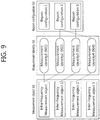
- FIG. 9 illustrates an example of measurement configuration in the terminal.
- the measurement identity 1 (901) connects an intra-frequency measurement object with a reporting configuration 1.
- the terminal performs intra frequency measurement, and the reporting configuration 1 is used to determine criterion and type of the measurement result reporting.
- the measurement identity 2 (902) is connected to the intra-frequency measurement object, but connects the intra-frequency measurement object to the reporting configuration 2.
- the terminal performs measurement and the reporting configuration 2 is used to determine criterion and type of the measurement result reporting.
- a measurement identity 1 (901) and a measurement identity 2 (902) even if a measurement result with respect to the intra-frequency measurement object satisfies one of reporting configuration 1 and reporting configuration 2, the terminal transmits the measurement result.
- the measurement identity 3 (903) connects the inter-frequency measurement object 1 to the reporting configuration 3. If the measurement result with respect to the inter-frequency measurement object 1 satisfies a reporting condition included in the reporting configuration 1, the terminal reports the measurement result.
- the measurement identity 4 (904) connects the inter-frequency measurement object 2 to the reporting configuration 2. If the measurement result with respect to the inter-frequency measurement object 2 satisfies a reporting condition included in the reporting configuration 2, the terminal reports the measurement result.
- the measurement object, reporting configuration and/or measurement identity may be added, changed, and/or removed. This may be indicated by sending a new measurement configuration message or the measurement configuration change message to the terminal.
- FIG. 10 illustrates an example of removing the measurement identity. If the measurement identity 2 (902) is removed, measurement with respect to a measurement object associated with the measurement identity 2 (902) is stopped and the measurement reporting is not transmitted. The measurement object associated with the removed measurement identity or the reporting configuration may not be changed.
- FIG. 11 illustrates an example of removing the measurement object. If the inter-frequency measurement object 1 is removed, the terminal also remove the measurement identity 3 (903) associated with the inter-frequency measurement object 1. Measurement with respect to the inter-frequency measurement object 1 is stopped and the measurement reporting is not transmitted. However, the reporting configuration associated with the remove inter-frequency measurement object 1 may not be changed or removed.
- the terminal also removes a measurement identity associated with the reporting configuration.
- the terminal stops measurement with respect to the measurement object associated with the associated measurement identity.
- the measurement object associated with the removed reporting configuration may not be changed or removed.
- the measurement reporting may include a measurement identity, measured quality of the serving cell and a measurement result of the neighboring cell.
- the measurement identity identifies a measurement object to which the measurement report is triggered.
- the measurement result of the neighboring cell may include a cell identity and measured quality of the neighboring cell.
- the measured quality may include at least one of Reference Signal Received Power (RSRP) and Reference Signal Received Quality (RSRQ).
- FIG. 12 is a flowchart illustrating a method for performing a logged MDT.
- the logged measurement configuration may be included in an RRC message and transmitted as a downlink control channel.
- the logged measurement configuration may include at least one of pieces of information about a TCE ID, a reference time that is a criterion in performing logging, logging duration, a logging interval, and an area configuration.
- the logging interval is indicative of an interval in which a measured result is stored.
- the logging duration is indicative of duration in which UE performs a logged MDT.
- the reference time is indicative of the time, that is, a criterion for duration in which a logged MDT is performed.
- the area configuration is indicative of an area on which UE has been requested to perform logging.
- the UE starts a validity timer when it receives the logged measurement configuration.
- the validity timer means the lifetime of the logged measurement configuration, and may be specified based on information about logging duration.
- the duration of the validity timer may also indicate the validity of a measured result owned by the UE in addition to the valid lifetime of the logged measurement configuration.
- a procedure in which the UE receives the logged measurement configuration and a corresponding overall procedure is performed as described above is called a configuration phase.
- the UE When the UE enters an RRC idle state (S1221), the UE logs a measured result while the validity timer is driven (S1222).
- the value of the measured result may be RSRP, RSRQ, Received Signal Code Power (RSCP), or Ec/No.
- Information obtained by logging the measured result is called a logged measurement and/or a measured result log.
- a temporal phase in which UE logs a measured result more than once is called a logging phase.
- the execution of a logged MDT based on a logged measurement configuration by UE may be changed depending on a place where the UE is present.
- FIG. 13 is a diagram illustrating an example of a logged MDT according to a logging area.
- a network may configure a logging area, that is, an area in which UE needs to perform logging.
- the logging area may be represented in the form of a cell list or may be represented in the form of a tracking area/location area list. If a logging area has been configured for the UE, the UE stops logging when it deviates from the logging area.
- a first area 1310 and a third area 1330 are areas configured as a logging area, and a second area 1320 is an area in which logging is not permitted.
- the UE performs logging in the first area 1310, but does not perform logging in the second area 1320.
- the UE performs logging again when it moves from the second area 1320 to the third area 1330.
- FIG. 14 is a diagram illustrating an example of a logged MDT according to a change of an RAT.
- the UE performs logging only when it camps on an RAT through which a logged measurement configuration has been received, but stops logging in other RATs.
- the UE may log cell information of another RAT in addition to the RAT in which the UE camps on.
- a first area 1410 and a third area 1430 are E-UTRAN areas, and a second area 1420 is a UTRAN area.
- a logged measurement configuration is received from the E-UTRAN. The UE does not perform MDT measurements when it enters the second area 1420.
- the UE if the UE enters an RRC connected state (S1231) and has logged measurements to be reported, the UE notifies an eNB that it has the logged measurements to be reported (S1232).
- the UE may notify the eNB that it has the logged measurements.
- the UE performs handover it may notify a target handover cell that it has the logged measurements.
- the eNB of the logged measurements may include including a logged measurement availability indicator, that is, indication information providing notification of the presence of the logged measurements, in an RRC message transmitted from the UE to the eNB and sending the RRC message.
- the RRC message may be an RRC connection establishment-complete message, an RRC connection re-establishment-complete message, an RRC reconfiguration-complete message, or a handover-complete message.
- the eNB When the eNB receives a signal providing notification of the presence of the logged measurements from the UE, it requests the UE to report the logged measurements (S1233).
- To request the report on the logged measurements may include including a logged measurement reporting request parameter regarding information indicative of the logged measurements in an RRC message and sending the RRC message.
- the RRC message may be a UE information request message.
- the UE When the UE receives the request for the report on the logged measurements from the eNB, it reports the logged measurements to the eNB (S1234).
- To report the logged measurements to the eNB may include including a logged measurement report, including the logged measurements, in an RRC message and sending the RRC message to the eNB.
- the RRC message may be a UE information report message.
- the UE In reporting the logged measurements, the UE may report all of the logged measurements owned by the UE to the eNB or some of the logged measurements owned by the UE to the eNB at a point of time at which the report is made. If some of the logged measurements owned by the UE is reported, the reported some logged measurements may be discarded.
- a phase in which a process of notifying, by UE, an eNB of the presence of logged measurements, receiving a request for a report from the eNB, and reporting the logged measurements is performed as described above is called a reporting phase.
- the MDT measurements may include a cell identity and the signal quality and/or signal intensity of a cell.
- the MDT measurements may include a measurement time and a measurement place. Table 3 below illustrates contents logged by UE.
- Information logged at different logging points of time may be stored so that it is divided into different log entries as follows.
- FIG. 15 is a diagram illustrating an example of logged measurements.
- the logged measurements include one or more log entries.
- the log entry includes a logging location, a logging time, a serving cell identity, a serving measured result, and a neighbor cell measured result.
- the logging location is indicative of a location in which UE has performed measurements.
- the logging time is indicative of the time when UE performed measurements. Information logged on a different logging time is stored in a different log entry.
- the serving cell identity may include a cell identity in Layer 3, which is called a Global Cell Identity (GCI).
- GCI Global Cell Identity
- the GCI is a set of a Physical Cell Identity (PCI) and a PLMN identity.
- UE may analyze and log indices related to performance of the UE in addition to a wireless environment.
- the indices may include a throughput and an erroneous transmission/reception rate).
- the aforementioned logging phase and reporting phase may be present in the logging duration in plural times (S1241, S1242).
- the eNB may record/store the logged measurements in a TCE when it receives a report on the logged measurements.
- the UE After the validity timer expires, that is, after a lapse of the logging duration, if the UE has logged measurements that have not yet been reported, the UE performs a procedure for reporting the logged measurements to the eNB.
- a phase in which an overall procedure for reporting the logged measurements to the eNB is performed is called a post-reporting phase.
- the UE discards the logged measurement configuration and starts a conservation timer. After the logging duration is terminated, the UE stops MDT measurements. However already logged measurements remain without being discarded. The conservation timer is indicative of the lifetime of the remaining logged measurements.
- the UE may report logged measurements that have not yet been reported to the eNB.
- the aforementioned procedures for reporting the logged measurements may be performed (S1252, S1253, and S1254).
- the conservation timer expires, the remaining logged measurements may be discarded.
- the eNB may record/store the logged measurements when a report on the logged measurements is received.
- the conservation timer may be fixed to a predetermined value for the UE and may be previously set in the UE.
- the value of the conservation timer may be 48 hours.
- the value of the conservation timer may be included in a logged measurement configuration and delivered to the UE or may be included another RRC message and delivered to the UE.
- the UE may update an existing logged measurement configuration with the newly obtained logged measurement configuration.
- a validity timer may be started again from the time when the logged measurement configuration is newly received.
- logged measurements based on a prior logged measurement configuration may be discarded.
- FIG. 16 is a diagram illustrating an example of an immediate MDT.
- the immediate MDT is based on a Radio Resource Management (RRM) measurement and report mechanism.
- RRM Radio Resource Management
- information related to a location is added when a measured report is made and reported to an eNB.
- UE receives an RRC connection reconfiguration message (S1610) and sends an RRC connection reconfiguration-complete message (S1620). Accordingly, the UE enters an RRC connected state.
- the UE may receive a measurement configuration by receiving the RRC connection reconfiguration message.
- the measurement configuration is received through the RRC connection reconfiguration message, but may be included in an RRC message according to an example and transmitted.
- the UE performs measurements and evaluations in the RRC connected state (S1631) and reports a measured result to an eNB (S1632).
- the measured result may provide accurate location information, if possible, as in an example of Global Navigation Satellite System (GNSS) location information.
- GNSS Global Navigation Satellite System
- neighbor cell measurement information that may be used to determine the location of the UE may be provided.
- MBMS Multimedia Broadcast and Multicast Service
- a logical channel MCCH channel or MTCH channel may be mapped to a transport channel MCH channel for the MBMS.
- the MCCH channel sends an MBMS-related RRC message, and the MTCH channel sends traffic of a specific MBMS service.
- a single MCCH channel is present in each MBMS Single Frequency Network (MBSFN) area in which the same MBMS information/traffic is transmitted. If a single cell provides a plurality of MBSFN areas, UE may receive a plurality of MCCH channels. If an MBMS-related RRC message is changed in a specific MCCH channel, a PDCCH channel sends an indicator indicative of an MBMS Radio Network Temporary Identity (M-RNTI) and a specific MCCH channel.
- M-RNTI MBMS Radio Network Temporary Identity
- UE supporting the MBMS may receive the M-RNTI and the MCCH indicator through the PDCCH channel, may check that the MBMS-related RRC message has been changed in a specific MCCH channel, and may receive the specific MCCH channel.
- the RRC message of the MCCH channel may be changed for each change cycle and repeatedly broadcasted for each repetition cycle.
- UE may also be provided with a dedicated service while it is provided with an MBMS service.
- a user may watch TV through an MBMS service through his or her smart phone and simultaneously perform chatting using an Instant Messaging (IM) service, such as MSN or Skype, using the smart phone.
- IM Instant Messaging
- the MBMS service is provided through an MTCH received by several UE, and a service provided to each UE, such as an IM service, may be provided through a dedicated bearer, such as a DCCH or DTCH.
- a specific eNB may use several frequencies at the same time.
- a network may select one of the several frequencies, may provide an MBMS service only the selected frequency, and may provide dedicated bearers to respective UEs in all the frequencies.
- the UE need to perform handover to the frequency through which the MBMS service is provided.
- the UE sends an MBMS interest indication to an eNB. That is, if the UE wants to receive the MBMS service, it sends an MBMS interest indication to the eNB.
- the eNB recognizes that the UE wants to receive the MBMS service and moves the UE to the frequency through which the MBMS service is provided.
- the MBMS interest indication means information indicating that the UE wants to receive the MBMS service and additionally includes information about a frequency to which the UE wants to move.
- the UE that wants to receive a specific MBMS service first checks frequency information and broadcasting time information through which the specific MBMS service is provided. If the MBMS service is already broadcasted or starts to be broadcasted, the UE sets the highest priority in a frequency through which the MBMS service is provided. The UE moves to a cell that provides the MBMS service by performing a cell reselection procedure using the reconfigured frequency priority information, and receives the MBMS service.
- the highest priority may be considered to have been applied to the corresponding frequency during an MBMS session as long as the following situation continues in the state in which a reselected cell broadcasts SIB13.
- the aforementioned MDT may be applied in relation to an MBMS.
- a network may enable specific UE to report information related to an MBMS to the network.
- a series of procedures, including a corresponding configuration from a network and/or an UE MBMS information reporting operation, may be implemented as in the aforementioned MDT, which may be called an MBMS MDT.
- a network may select UE for an MBMS MDT based on the capabilities of the UE and/or the consent of a user.
- an MBMS service is broadcasted and provided on an MBSFN area, and UE provided with the MBMS service does not provide corresponding feedback. Accordingly, the network rarely checks the MBMS reception status of the UE. Accordingly, the network may perform a configuration in UE so that MBMS MDT management is performed regardless of the MBMS reception status of the UE.
- the UE consumes power for the purpose of the reporting of MBMS information. If the reporting of MBMS information depends on the improvement of MBMS service reception from a viewpoint of a user, excessive consumption of UE-side power attributable to the improvement may not be preferred. Accordingly, a method capable of improving MBMS service reception for UE while preventing excessive consumption of UE-side power needs to be proposed.
- FIG. 17 is a diagram illustrating a method for reporting MBMS information in accordance with an embodiment of the present invention.
- the MBMS reporting configuration may include configuration information for obtaining, logging, and reporting information related to the MBMS service reception of the UE.
- the configuration information set in the UE through the MBMS reporting configuration may be implemented as follows.
- the MBMS reporting configuration may be provided to UE through broadcast signaling (e.g., signaling through a BCCH and/or an MCCH).
- UE may receive an MBMS reporting configuration provided through broadcast signaling and may determine whether there is user consent for an MBMS information report according to the MBMS reporting configuration. If user consent is present, the UE may determine to apply the MBMS reporting configuration. If user consent is not present, the UE may neglect the received MBMS reporting configuration.
- the user consent for performing the MBMS information report may be previously set in the UE or may be set in an application which uses Open Mobile Alliance (OAM) Device Management (DM), for example.
- OFAM Open Mobile Alliance
- DM Device Management
- the MBMS reporting configuration may be provided to UE through dedicated signaling (e.g., signaling through a DCCH, etc.).
- An RRC message for the MBMS reporting configuration may be newly defined.
- the MBMS reporting configuration may be further included in an existing RRC message.
- the MBMS reporting configuration may be additionally included in a logged measurement configuration message. If a logged measurement configuration is used through a logged measurement configuration message, the logged measurement configuration message may be required to indicate whether UE will perform an MBMS information report. To this end, the aforementioned MBMS logging purpose information may be included in the logged measurement configuration message. Meanwhile, if a logged measurement configuration message is solely used for an MBMS information report, the logged measurement configuration message may further include information indicating that measurement logging for a logged MDT needs to be omitted.
- the UE determines whether the logging of the MBMS information is permitted (S1720).
- the determination of whether the logging of the MBMS information by the UE is permitted may include determining whether the logging of the MBMS information is permitted based on a logging scope configured in the UE.
- the logging scope may be configured in such a manner that it is included in the aforementioned MBMS reporting configuration and provided to the UE or may have been previously configured in the UE.
- the UE may determine that the logging of the MBMS information is permitted within a logging permission scope indicated by the logging scope.
- the UE may determine whether the logging of the MBMS information is permitted based on the logging scope configured in the UE as follows.
- One or more of the aforementioned criteria for determining whether the acquisition and logging of the MBMS information are permitted may be combined and implemented so that whether the acquisition and logging of the MBMS information are permitted is determined.
- UE may determine whether the logging of MBMS information is permitted based on a logging scope in which an MBSFN area and a PLMN have been combined.
- the UE which has determined that the acquisition and logging of the MBMS information have been permitted executes the acquisition and logging of the MBMS information (S1730).
- the UE may perform MBMS measurements in order to obtain the MBMS information.
- the UE may perform measurements on a frequency and/or subframe in which an (interest) MBMS service is provided and may obtain a measured result.
- the UE may include a result of the measurement of an MBMS service in MBMS information.
- the UE may include information about the location of the UE when obtaining and logging the MBMS information in the MBMS information.
- the acquisition and logging of the MBMS information by the UE may be performed based on the MBMS logging execution information of the MBMS reporting configuration.
- the acquisition and logging of the MBMS information by the UE may be periodically performed.
- an MBMS logging cycle may be set in the UE.
- the MBMS logging cycle may be set in the UE according to the logging interval of MBMS logging execution information included in an MBMS reporting configuration.
- the UE may perform MBMS measurements at a logging point of time according to the MBMS logging cycle, may obtain MBMS information including a measured result, and may log the MBMS information.
- a timer may be set.
- the timer may be set as an MBMS logging cycle value. The timer is restarted right after it expires, and the UE may obtain and log MBMS information when the timer expires.
- the acquisition and logging of the MBMS information by the UE may be performed when a specific event occurs.
- an MBMS logging event may be set in the UE.
- the MBMS logging event may be set in the UE through the logging event of MBMS logging execution information included in an MBMS reporting configuration.
- the logging event may be related to the reception status of an MBMS service provided to the UE and/or the reception quality of the MBMS service. If the reception of an MBMS service fails or an MBMS service having lower quality than a specific threshold is received, the UE may perform MBMS measurements and may obtain and log MBMS information including a measured result.
- UE may determine the acquisition and logging of MBMS information using which one of the two methods based on the configuration of a network. For example, separate information indicative of a method of obtaining and logging, by UE, MBMS information may be provided by a network. In another example, a method of obtaining and logging MBMS information may be indicated by an MBMS reporting configuration. If a logging interval is included in the MBMS reporting configuration, but a logging event is not included therein, the UE may perform the periodic acquisition and logging of MBMS information. If a logging event is included in the MBMS reporting configuration, but a logging interval is not included therein, the UE may perform the event-based acquisition and logging of MBMS information. If information indicative of a method of obtaining and logging MBMS information is included in the MBMS reporting configuration, the UE may perform the acquisition and logging of MBMS information according to the indicated method.
- whether UE will obtain and log MBMS information based on which one of the two methods may be previously set in the UE.
- the logged MBMS information may be stored as one logged entry.
- Each of logged entries related to a piece of logged MBMS information may include the following numerated information.
- the MBMS information that may be logged by the UE may be obtained and/or determined from a serving cell and/or a non-serving cell.
- the UE reports the logged MBMS information to the network (S 1740).
- the logged MBMS information to the network may be performed as in an existing logged MDT.
- the UE may include a logged MBMS information availability indicator, indicating that there is logged MBMS information to be reported, in an RRC connection establishment-complete message, an RRC connection reconfiguration-complete message, or an RRC connection re-establishment-complete message, and send the message.
- the UE may report the logged MBMS information to the network at a specific report time interval during an RRC connected state.
- the specific report time interval may be set by the network.
- the reporting of the logged MBMS information by the UE may include immediately reporting the obtained and/or logged MBMS information to the network after MBMS measurements.
- the UE may immediately report the MBMS information to the network without a request for a report by the network.
- UE in an RRC connected state may obtain MBMS information and immediately report the MBMS information to the network.
- UE in the RRC connected state may include MBMS information in an RRC connection establishment-complete message, an RRC connection re-establishment-complete message, or a separate RRC message and send the message to a network.
- FIG. 18 is a diagram illustrating an example of a method of reporting MBMS information in accordance with an embodiment of the present invention.
- UE receives an MBMS reporting configuration from an LTE cell 1 (S1810).
- the MBMS reporting configuration may be transmitted through dedicated signaling for the UE.
- the MBMS reporting configuration may be included in a specific RRC message and provided to the UE.
- the reporting configuration may be provided to the UE through broadcast signaling.
- the MBMS reporting configuration may include a logging scope, logging duration T D , and a logging interval T I as MBMS logging execution information.
- the logging scope may include an MBSFN area list including an MBSFN area in which logging is permitted.
- the MBSFN area list may include an MBSFN areal and an MBSFN area3.
- the UE camps on the LTE cell 1 and may receive system information transmitted by the LTE cell 1.
- the UE may be aware that the LTE cell 1 is an MBMS cell providing an MBMS service based on SIB3 of the system information received from the LTE cell 1.
- the UE may be aware that an MBSFN area related to an MBMS service provided by the LTE cell 1 is the MBSFN area1 through the SIB13. Since the MBSFN areal is included in an MBSFN area list, the UE may determine that the logging of MBMS information is permitted.
- the UE which has determined that the logging of MBMS information is permitted may periodically log MBMS information at the logging interval T I for the logging duration T D . Accordingly, while the UE receives the MBMS service (S1825), the UE measures a reception signal related to the MBMS service and obtains and logs MBMS information (SI821, S1822). In order to obtain and log periodic MBMS information at the logging interval T I , the UE may set and drive a timer. The timer may be set as the logging interval T I , and the UE may execute the acquisition and logging of the MBMS information whenever the timer expires.
- the UE may perform wireless measurements on a frequency and/or subframe in which the MBMS service is received at the logging interval T I .
- the UE may include a measured result in the MBMS information.
- the UE may include location information indicative of the location of the UE in the MBMS information.
- the MBMS information obtained and logged by the UE may be implemented like the logged MBMS information described with reference to FIG. 17 .
- MBMS information logged by the UE at each step may be logged as a single log entry.
- the UE While in motion, the UE may move from the LTE cell 1 to an LTE cell 2 (S1830).
- the cell movement of the UE may be performed through cell reselection and/or handover.
- the UE camps on the LTE cell 2 and may receive system information transmitted by the LTE cell 2.
- the UE may be aware that the LTE cell 2 is an MBMS cell providing an MBMS service through SIB3 of the system information received from the LTE cell 2.
- the UE may be aware that an MBSFN area related to an MBMS service provided by the LTE cell 2 is an MBSFN area2 through the SIB13. Since the MBSFN area2 is not included in the MBSFN area list, the UE may determine that the logging of MBMS information is not permitted.
- the UE which has determined that the logging of MBMS information is not permitted may not log MBMS information even during the logging duration T D . Accordingly, although the UE receives the MBMS service (S1845), it may perform measurements on a frequency and/or subframe in which the MBMS service is provided.
- the UE While in motion, the UE may move from the LTE cell 2 to an LTE cell 3 (S1850).
- the cell movement of the UE may be performed through cell reselection and/or handover.
- the UE camps on the LTE cell 3 and may receive system information transmitted by the LTE cell 3.
- the UE may be aware that the LTE cell 3 is an MBMS cell providing an MBMS service through SIB3 of the system information received from the LTE cell 3.
- the UE may be aware that an MBSFN area related to an MBMS service provided by the LTE cell 3 is the MBSFN area3 through the SIB13. Since the MBSFN area3 is included in the MBSFN area list, the UE may determine that the logging of MBMS information is permitted.
- the UE which has determined that the logging of MBMS information is permitted in the LTE cell 3 may periodically log MBMS information at the logging interval T I for the logging duration T D . Accordingly, while the UE receives the MBMS service (S1865), the UE measures a reception signal related to the MBMS service and obtains and logs MBMS information (S1861, S1862). In order to obtain and log periodic MBMS information at the logging interval T I , the UE may set and drive a timer. The timer may be set as the logging interval T I , and the UE may execute the acquisition and logging of MBMS information whenever the timer expires.
- the UE may perform wireless measurements on a frequency and/or subframe in which the MBMS service is received at the logging interval T I .
- the UE may include a measured result in the MBMS information.
- the UE may include location information indicative of the location of the UE in the MBMS information.
- the MBMS information obtained and logged by the UE may be implemented like the logged MBMS information described with reference to FIG. 17 .
- the MBMS information logged by the UE at each step may be logged as a single log entry.
- the UE may determine to stop the acquisition and logging of MBMS information (S1870).
- the UE which has stopped the acquisition and logging of the MBMS information may report the logged MBMS information to the network.
- the UE may send a logged MBMS information availability indicator to the network (S1881).
- the logged MBMS information availability indicator may be included in an RRC message and transmitted.
- the logged MBMS information availability indicator may be included in an RRC connection establishment-complete message, an RRC connection reconfiguration-complete message, an RRC connection re-establishment-complete message, or a UE information message and transmitted to the network.
- the logged MBMS information availability indicator has been illustrated as being transmitted to the LTE cell, but the UE may send the logged MBMS information availability indicator to a corresponding serving cell if the UE uses another cell as a serving cell.
- the LTE cell or another serving cell which has received the logged MBMS information availability indicator may send a logged MBMS information report request that requests the reporting of logged MBMS information to the UE (S1882). Thereafter, the UE may send the logged MBMS information to the LTE cell or another serving cell in response to the MBMS information report request (S1883).
- the logging scope configured in the UE may be specified as the MBSFN area.
- the UE has determined whether the logging of MBMS information is permitted based on an MBSFN area related to an MBMS service. If the logging of MBMS information is permitted, the UE has periodically executed the acquisition and logging of MBMS information within a specific duration interval based on the logging duration T D and the logging interval T I .
- UE may determine whether the logging of MBMS information is permitted based on the PLMN of an MBMS cell.
- UE may obtain MBMS information in response to a logging event and immediately report the logged MBMS information to a network. Such a method of reporting MBMS information is described with reference to FIG. 19 .
- FIG. 19 is a diagram illustrating another example of a method of reporting MBMS information in accordance with an embodiment of the present invention.
- UE receives an MBMS reporting configuration from an LTE cell 1 (S1910).
- the MBMS reporting configuration may be transmitted through dedicated signaling for the UE.
- the MBMS reporting configuration may be included in a specific RRC message and provided to the UE.
- the MBMS reporting configuration may be provided to the UE through broadcast signaling.
- the MBMS reporting configuration may include a logging scope and a logging event as MBMS logging execution information.
- the logging scope may include a PLMN list including a PLMN in which logging is permitted.
- the PLMN list may include a PLMN1 and a PLMN3.
- the logging event may indicate an MBMS service failure and MBMS service deterioration.
- the UE camps on the LTE cell 1 and may receive system information transmitted by the LTE cell 1.
- the UE may check that the corresponding cell is a cell based on the PLMN1 through the system information transmitted by the LTE cell 1. Accordingly, the UE may determine that the acquisition/logging of MBMS information are permitted while camping on the LTE cell 1.
- the UE may perform the acquisition/logging of MBMS information based on a logging event.
- the UE receives an MBMS service from the LTE cell 1 and may determine whether or not to perform the acquisition/logging of MBMS information.
- the UE has received the MBMS service, but may detect that MBMS service reception quality deterioration has occurred (S1921). Accordingly, the UE may determine the occurrence of a logging event and determine to obtain MBMS information. The UE measures the MBMS service and obtains MBMS information (S1922).
- the UE may perform wireless measurements on a frequency and/or subframe in which the MBMS service is provided.
- the UE may include a measured result in the MBMS information.
- the UE may include location information indicative of the location of the UE in the MBMS information.
- the MBMS information obtained at step S1922 has been triggered by a reporting event configured by an MBMS reporting configuration, and thus the UE may include information indicative of an MBMS information acquisition reason in the MBMS information. Acquisition reason information may be configured to indicate MBMS service reception quality deterioration. Additionally, if the UE is able to check a reason for MBMS service reception quality deterioration, MBMS service deterioration reason information may be included in the MBMS information. In addition, the obtained MBMS information may be implemented like the logged MBMS information described with reference to FIG. 17 .
- the UE reports the obtained MBMS information to the LTE cell 1 (S1923).
- the UE While in motion, the UE may move from the LTE cell 1 to an LTE cell 2 (S1930).
- the cell movement of the UE may be performed through cell reselection and/or handover.
- the UE camps on the LTE cell 2 and may receive system information transmitted by the LTE cell 2.
- the UE may check that the corresponding cell is a cell based on a PLMN2 through the system information transmitted by the LTE cell 2. Accordingly, the UE may determine that the acquisition/logging of MBMS information is not permitted while camping on the LTE cell 2.
- a logging event related to an MBMS service is generated while the UE receives the MBMS service from the LTE cell 2, the UE does not obtain MBMS information.
- the UE receives the MBMS service having low reception quality (S1940), but does not perform measurements on the MBMS service because the acquisition of MBMS information is not permitted.
- the UE While in motion, the UE may move from the LTE cell 2 to the LTE cell 3 (S1930).
- the cell movement of the UE may be performed through cell reselection and/or handover.
- the UE camps on an LTE cell 3 and may receive system information transmitted by the LTE cell 3.
- the UE may check that the corresponding cell is a cell based on the PLMN3 through the system information transmitted by the LTE cell 3. Accordingly, the UE may determine that the logging of MBMS information is permitted while camping on the LTE cell 3.
- the UE may perform the acquisition/logging of MBMS information based on a logging event.
- the UE receives an MBMS service from the LTE cell 3 and may determine whether or not to perform the acquisition/logging of MBMS information.
- the UE may detect that the reception of the MBMS service from the LTE cell 3 has failed (S1961). Accordingly, the UE may determine the occurrence of a logging event and determine to log MBMS information. The UE measures the MBMS service and obtains MBMS information (S1962).
- the UE may perform wireless measurements on a frequency and/or subframe in which the MBMS service is provided.
- the UE may include a measured result in the MBMS information.
- the UE may include location information indicative of the location of the UE in the MBMS information.
- the MBMS information obtained at step S1962 has been triggered by a reporting event configured in an MBMS reporting configuration, and thus the UE may include information indicative of an MBMS information acquisition reason in the MBMS information. Acquisition reason information may be configured to indicate an MBMS service reception failure. Additionally, if the UE is able to check a reason for an MBMS service reception failure, a reason for the MBMS service reception failure may be included in the MBMS information. In addition, the obtained MBMS information may be implemented like the logged MBMS information described with reference to FIG. 17 .
- the UE reports the logged MBMS information to the LTE cell 3 (S1963).
- a network can set an MBMS information acquisition/logging scope for the report of MBMS information in UE so that the UE can log MBMS information and report the logged MBMS information only when the logging scope is satisfied. Accordingly, the measurements of an MBMS service and the reporting of MBMS information by UE can be controlled. This enables control of power consumed for the reporting of MBMS information by UE and enables control of signaling for the reporting of MBMS information. As a result, efficient power management and efficient management of radio resources for UE can be possible.
- FIG. 20 is a block diagram showing a wireless device in which an embodiment of the present invention is implemented.
- the device may be implemented as UE or a network system for performing a cell reselection method in accordance with an embodiment of the present invention.
- the wireless device 2000 includes a processor 2010, memory 2020, and a Radio Frequency (RF) unit 2030.
- the processor 2010 implements the proposed functions, processes and/or methods.
- the processor 2010 may be configured to generate and provide an MBMS reporting configuration for the acquisition/logging and reporting of MBMS information.
- the processor 2010 may be configured to determine whether the logging of MBMS information is permitted based on a logging scope.
- the processor 2010 may be configured to obtain, log, and report MBMS information.
- the processor 2010 may be configured to perform the embodiments of the present invention described with reference to FIGS. 17 to 19 .
- the RF unit 2030 is connected to the processor 2010, and sends and receives radio signals.
- the processor may include Application-Specific Integrated Circuits (ASICs), other chipsets, logic circuits, and/or data processors.
- the memory may include Read-Only Memory (ROM), Random Access Memory (RAM), flash memory, memory cards, storage media and/or other storage devices.
- the RF unit may include baseband circuits for processing radio signals.
- the aforementioned scheme may be implemented as a module (process or function) that performs the aforementioned function.
- the module may be stored in the memory and executed by the processor.
- the memory may be placed inside or outside the processor and may be connected to the processor using a variety of well-known means.
Landscapes
- Engineering & Computer Science (AREA)
- Computer Networks & Wireless Communication (AREA)
- Signal Processing (AREA)
- Multimedia (AREA)
- Mobile Radio Communication Systems (AREA)
- Small-Scale Networks (AREA)
Priority Applications (1)
| Application Number | Priority Date | Filing Date | Title |
|---|---|---|---|
| EP18191708.9A EP3429258B1 (en) | 2013-02-14 | 2014-02-14 | Method for reporting mbms information in wireless communication system and device for supporting same |
Applications Claiming Priority (2)
| Application Number | Priority Date | Filing Date | Title |
|---|---|---|---|
| US201361765006P | 2013-02-14 | 2013-02-14 | |
| PCT/KR2014/001243 WO2014126424A1 (ko) | 2013-02-14 | 2014-02-14 | 무선 통신 시스템에서 mbms 정보 보고 방법 및 이를 지원하는 장치 |
Related Child Applications (2)
| Application Number | Title | Priority Date | Filing Date |
|---|---|---|---|
| EP18191708.9A Division EP3429258B1 (en) | 2013-02-14 | 2014-02-14 | Method for reporting mbms information in wireless communication system and device for supporting same |
| EP18191708.9A Division-Into EP3429258B1 (en) | 2013-02-14 | 2014-02-14 | Method for reporting mbms information in wireless communication system and device for supporting same |
Publications (3)
| Publication Number | Publication Date |
|---|---|
| EP2958364A1 EP2958364A1 (en) | 2015-12-23 |
| EP2958364A4 EP2958364A4 (en) | 2016-10-19 |
| EP2958364B1 true EP2958364B1 (en) | 2018-12-12 |
Family
ID=51354362
Family Applications (4)
| Application Number | Title | Priority Date | Filing Date |
|---|---|---|---|
| EP14752065.4A Active EP2958363B1 (en) | 2013-02-14 | 2014-02-14 | Method for reporting mbms information in wireless communication system and device for supporting same |
| EP18191708.9A Active EP3429258B1 (en) | 2013-02-14 | 2014-02-14 | Method for reporting mbms information in wireless communication system and device for supporting same |
| EP14752166.0A Active EP2958364B1 (en) | 2013-02-14 | 2014-02-14 | Method for reporting mbms information in wireless communication system and device for supporting same |
| EP14751270.1A Active EP2958362B1 (en) | 2013-02-14 | 2014-02-14 | Method for reporting mbms information in wireless communication system and device for supporting same |
Family Applications Before (2)
| Application Number | Title | Priority Date | Filing Date |
|---|---|---|---|
| EP14752065.4A Active EP2958363B1 (en) | 2013-02-14 | 2014-02-14 | Method for reporting mbms information in wireless communication system and device for supporting same |
| EP18191708.9A Active EP3429258B1 (en) | 2013-02-14 | 2014-02-14 | Method for reporting mbms information in wireless communication system and device for supporting same |
Family Applications After (1)
| Application Number | Title | Priority Date | Filing Date |
|---|---|---|---|
| EP14751270.1A Active EP2958362B1 (en) | 2013-02-14 | 2014-02-14 | Method for reporting mbms information in wireless communication system and device for supporting same |
Country Status (7)
| Country | Link |
|---|---|
| US (3) | US9973902B2 (ja) |
| EP (4) | EP2958363B1 (ja) |
| JP (6) | JP6047247B2 (ja) |
| KR (3) | KR102160665B1 (ja) |
| CN (3) | CN105027607B (ja) |
| RU (1) | RU2633378C2 (ja) |
| WO (3) | WO2014126423A1 (ja) |
Families Citing this family (40)
| Publication number | Priority date | Publication date | Assignee | Title |
|---|---|---|---|---|
| EP2897416B1 (en) * | 2012-09-13 | 2019-07-24 | LG Electronics Inc. | Operating method for acquiring system information in wireless communication system, and apparatus for supporting same |
| KR102036061B1 (ko) * | 2013-04-08 | 2019-11-26 | 삼성전자 주식회사 | 무선 통신 시스템에서 단말기가 mbms 관련 측정 정보를 기록하고 보고하는 방법 및 장치 |
| WO2015062008A1 (zh) | 2013-10-31 | 2015-05-07 | 华为技术有限公司 | 广播多播单频网络测量数据的传输方法和装置 |
| JP6031534B2 (ja) * | 2014-01-14 | 2016-11-24 | 宏達國際電子股▲ふん▼有限公司 | 無線通信システムにおいてmbmsmdtを行う方法 |
| GB2522671B (en) * | 2014-01-31 | 2017-10-11 | Samsung Electronics Co Ltd | Measurement in MBMS |
| EP3101923B1 (en) * | 2014-01-31 | 2018-09-26 | Kyocera Corporation | Mbms measurement control method and user terminal |
| CN106031215B (zh) * | 2014-03-13 | 2019-08-02 | Lg 电子株式会社 | 在无线通信系统中执行mbms mdt的方法和装置 |
| JP6105807B2 (ja) * | 2014-03-20 | 2017-03-29 | 京セラ株式会社 | 移動局、測定制御方法、及びプロセッサ |
| CN106165525B (zh) * | 2014-04-03 | 2019-11-08 | 诺基亚技术有限公司 | Mbsfn测量和drx、针对不同传输类型的不同drx设置 |
| CN105376718B (zh) * | 2014-08-25 | 2020-03-31 | 中兴通讯股份有限公司 | Lte集群通信的方法、用户设备及第一网元设备 |
| CN104301931A (zh) * | 2014-09-24 | 2015-01-21 | 中兴通讯股份有限公司 | 拥塞/过载的控制方法,系统,装置和基站 |
| CN105472650B (zh) * | 2014-09-26 | 2020-05-01 | 诺基亚技术有限公司 | 用于对组播-广播单频网络测量记录日志的方法和装置 |
| US10313909B2 (en) | 2014-10-03 | 2019-06-04 | Lg Electronics Inc. | Method and device for cell granularity reporting in wireless communication system |
| US20160112924A1 (en) * | 2014-10-15 | 2016-04-21 | Qualcomm Incorporated | Early radio link failure (rlf) declaration |
| WO2016073216A1 (en) | 2014-11-07 | 2016-05-12 | Nokia Technologies Oy | Packet number representation for multicast channel block error rate reporting |
| WO2016079573A1 (en) * | 2014-11-21 | 2016-05-26 | Telefonaktiebolaget L M Ericsson (Publ) | Method and apparatus for multimedia broadcast multicast service transmission |
| US10531427B2 (en) * | 2014-12-09 | 2020-01-07 | Qualcomm Incorporated | Enhanced system access for E-UTRAN |
| WO2016140538A1 (ko) * | 2015-03-03 | 2016-09-09 | 엘지전자 주식회사 | 무선 통신 시스템에서 mbms 관련 신호 송수신 방법 및 이를 위한 장치 |
| WO2016186415A1 (ko) | 2015-05-15 | 2016-11-24 | 엘지전자 주식회사 | 무선 통신 시스템에서 브로드캐스트 서비스를 제공하는 방법 및 이를 위한 장치 |
| ES2875602T3 (es) * | 2015-10-22 | 2021-11-10 | Ericsson Telefon Ab L M | Métodos y aparato relacionados con la mejora selectiva de señales de radio |
| US20180352454A1 (en) * | 2016-05-12 | 2018-12-06 | Telefonaktiebolaget Lm Ericsson (Publ) | MBMS Bearer Quality Evaluation |
| US20180049079A1 (en) * | 2016-08-12 | 2018-02-15 | Qualcomm Incorporated | Handover in wireless communications |
| KR102221346B1 (ko) * | 2017-03-16 | 2021-02-26 | 엘지전자 주식회사 | 시스템 정보 블록의 유효성을 판단하는 방법 및 이를 지원하는 장치 |
| KR102277946B1 (ko) * | 2017-03-17 | 2021-07-16 | 삼성전자주식회사 | 차량의 무선 통신을 지원하기 위한 방법들 및 장치들 |
| JP6980805B2 (ja) * | 2017-03-24 | 2021-12-15 | オッポ広東移動通信有限公司Guangdong Oppo Mobile Telecommunications Corp., Ltd. | 同期信号の測定方法及び関連デバイス |
| US10070256B1 (en) | 2017-08-16 | 2018-09-04 | Tile, Inc. | Tracking device operation in risk-classified geographic area |
| CN109996283A (zh) * | 2017-12-29 | 2019-07-09 | 普天信息技术有限公司 | 一种空闲态UE执行异频SCell测量的方法和装置 |
| JP7132336B2 (ja) * | 2018-01-11 | 2022-09-06 | テレフオンアクチーボラゲット エルエム エリクソン(パブル) | 多重アップリンクキャリアが関与する無線リンクの維持 |
| CN110662247B (zh) | 2018-06-29 | 2021-06-15 | 华为技术有限公司 | 通信方法和装置 |
| WO2020032771A1 (ko) * | 2018-08-10 | 2020-02-13 | 엘지전자 주식회사 | 무선 통신 시스템에서 단말의 셀 접속 방법 및 이를 위한 장치 |
| CN110944355B (zh) | 2018-09-21 | 2021-12-03 | 维沃移动通信有限公司 | 信息上报方法、接收方法、终端及网络设备 |
| EP3857941A4 (en) * | 2018-09-27 | 2021-11-17 | ZTE Corporation | PREPARATION OF MEASUREMENT REPORTS FOR NETWORK MAINTENANCE PROCESSES AND SYSTEMS |
| CN110147533B (zh) | 2019-01-24 | 2023-08-29 | 腾讯科技(深圳)有限公司 | 编码方法、装置、设备及存储介质 |
| US11792631B2 (en) | 2019-01-31 | 2023-10-17 | Huawei Technologies Co., Ltd. | Emergency call method and user terminal |
| KR20200097573A (ko) * | 2019-02-08 | 2020-08-19 | 삼성전자주식회사 | 차세대 이동 통신 시스템에서 유휴 상태의 단말이 셀 재선택시 측정할 셀 리스트를 갱신하는 방법 및 장치 |
| GB201909462D0 (en) * | 2019-07-01 | 2019-08-14 | Samsung Electronics Co Ltd | eMeas and MDT |
| JP7346575B2 (ja) * | 2019-08-08 | 2023-09-19 | 京セラ株式会社 | 通信制御方法 |
| WO2021153983A1 (en) * | 2020-01-29 | 2021-08-05 | Lg Electronics Inc. | Method and apparatus for reporting data transmission procedure failure for network optimization in a wireless communication system |
| CN113543190A (zh) * | 2020-04-17 | 2021-10-22 | 华为技术有限公司 | 一种通信方法和装置 |
| JP2023540666A (ja) * | 2020-07-03 | 2023-09-26 | 中興通訊股▲ふん▼有限公司 | マルチキャスト/ブロードキャストサービスセッションを処理する方法 |
Family Cites Families (38)
| Publication number | Priority date | Publication date | Assignee | Title |
|---|---|---|---|---|
| US7277706B2 (en) | 2003-02-12 | 2007-10-02 | Nokia Corporation | Provision of service contexts in a communication system |
| WO2004102901A1 (en) * | 2003-05-14 | 2004-11-25 | Philips Intellectual Property & Standards Gmbh | Methods and devices for counting user equipment units in a mobile radio telecommunication network |
| KR100703380B1 (ko) * | 2003-05-14 | 2007-04-03 | 삼성전자주식회사 | 멀티미디어 브로드캐스트/멀티캐스트 서비스를 지원하기 위한 제어정보 송수신 장치 및 방법 |
| GB0407902D0 (en) * | 2003-08-15 | 2004-05-12 | Koninkl Philips Electronics Nv | Feedback signalling for multicast data transmission |
| KR100976475B1 (ko) * | 2003-08-19 | 2010-08-18 | 엘지전자 주식회사 | 서비스 품질 (QoS) 측정보고 전송 방법 및 수신 방법 |
| CN101155038A (zh) * | 2006-09-29 | 2008-04-02 | 中兴通讯股份有限公司 | 获取多媒体广播/组播业务服务质量的方法和系统 |
| WO2008052383A1 (en) * | 2006-10-30 | 2008-05-08 | Huawei Technologies Co., Ltd. | Load control of ue mbms measurement reporting |
| US8396477B2 (en) * | 2007-03-23 | 2013-03-12 | Panasonic Corporation | Radio communication base station device and radio communication method to shorten a suspension time of an MBMS service when a user equipment moves from a single frequency network area to a non-single frequency network area |
| EP2140647A4 (en) | 2007-03-28 | 2014-05-21 | Ericsson Telefon Ab L M | MEASURING SYMBOLS OF CELL-SPECIFIC REFERENCES IN THE PRESENCE OF SINGLE-FREQUENCY NETWORK MBMS TRANSMISSIONS |
| AU2008245594A1 (en) * | 2007-04-27 | 2008-11-06 | Interdigital Technology Corporation | Method and apparatus of resource management for multimedia broadcast multicast services |
| JP2010526485A (ja) * | 2007-04-30 | 2010-07-29 | インターデイジタル テクノロジー コーポレーション | マルチメディアブロードキャスト/マルチキャストサービスに関するセル再選択およびハンドオーバ |
| JP5115273B2 (ja) * | 2008-03-28 | 2013-01-09 | 富士通株式会社 | 無線通信システム、無線基地局装置、マルチサービス管理装置 |
| CN101552950B (zh) | 2008-04-01 | 2011-04-20 | 大唐移动通信设备有限公司 | 多媒体广播业务控制数据传输方法及装置 |
| CN101772222B (zh) * | 2008-12-29 | 2013-03-20 | 中兴通讯股份有限公司 | 获取相邻基站所属小区mbsfn配置信息的方法和系统 |
| ES2368385T3 (es) | 2009-01-29 | 2011-11-16 | Lg Electronics Inc. | Esquema de transmisión de señales para una gestión eficaz del canal dedicado mejorado común. |
| KR100966566B1 (ko) | 2009-01-29 | 2010-06-29 | 엘지전자 주식회사 | 효율적인 공용 e-dch 관리를 위한 신호 전송 기법 |
| CN101835096B (zh) | 2009-03-13 | 2014-07-16 | 中兴通讯股份有限公司南京分公司 | 一种多媒体广播组播业务的承载方法及控制装置 |
| US9025520B2 (en) * | 2009-04-23 | 2015-05-05 | Electronics And Telecommunications Research Institute | Apparatus supporting an MBMS service |
| KR101707683B1 (ko) * | 2009-06-24 | 2017-02-16 | 엘지전자 주식회사 | 무선 통신 시스템상에서 단말의 측정 보고를 네트워크로 전송하는 방법 |
| WO2010151089A2 (en) * | 2009-06-26 | 2010-12-29 | Lg Electronics Inc. | Method of logging measurement result at handover failure in wireless communication system |
| US8254932B2 (en) * | 2009-09-28 | 2012-08-28 | Htc Corporation | Method of handling mobility in multimedia broadcast multicast service single frequency network in a wireless communication system and related communication device |
| CN102111714A (zh) * | 2009-12-29 | 2011-06-29 | 电信科学技术研究院 | 一种多媒体广播组播业务自优化处理方法及用户设备 |
| WO2011096692A2 (en) | 2010-02-03 | 2011-08-11 | Lg Electronics Inc. | Apparatus and method of reporting measurement result in wireless communication system |
| CN102158809B (zh) | 2010-02-12 | 2015-03-25 | 中兴通讯股份有限公司 | 一种判断mbms业务连续的方法和用户设备 |
| CN102215455A (zh) * | 2010-04-02 | 2011-10-12 | 中兴通讯股份有限公司 | 一种多媒体广播多播业务的测量上报方法及系统 |
| JP5298062B2 (ja) | 2010-04-26 | 2013-09-25 | シャープ株式会社 | 移動局装置、通信システム、セル再選択方法および集積回路 |
| WO2011149281A2 (ko) | 2010-05-26 | 2011-12-01 | 엘지전자 주식회사 | 무선 통신 시스템에서 로그된 측정 보고 방법 및 장치 |
| US8879459B2 (en) * | 2010-06-29 | 2014-11-04 | Zte Corporation | Method and system for sending counting response by user equipment in multimedia broadcast multicast service |
| KR20120080103A (ko) * | 2011-01-06 | 2012-07-16 | 주식회사 팬택 | Mdt 모드 전환 방법 및 이를 이용한 장치 |
| US9432900B2 (en) | 2011-04-08 | 2016-08-30 | Lg Electronics Inc. | Method for performing handover in wireless communication system and apparatus for same |
| WO2012148202A2 (ko) * | 2011-04-27 | 2012-11-01 | 엘지전자 주식회사 | 무선 통신 시스템에서 보고 방법 및 이를 지원하는 장치 |
| KR20120122335A (ko) * | 2011-04-28 | 2012-11-07 | 주식회사 팬택 | Mbms 서비스의 연속성을 제공하는 장치 및 방법 |
| CN102892078B (zh) | 2011-07-18 | 2015-03-04 | 上海贝尔股份有限公司 | 分布式mce架构中对mbms业务计数的方法和装置 |
| KR20130019732A (ko) | 2011-08-17 | 2013-02-27 | 주식회사 팬택 | Mbms 서비스에 관한 제어정보의 전송 장치 및 방법 |
| US9473967B2 (en) | 2011-11-17 | 2016-10-18 | Qualcomm Incorporated | Method and apparatus for physical layer measurements in multicast broadcast multimedia service systems |
| US8750181B2 (en) | 2012-05-14 | 2014-06-10 | Blackberry Limited | Maintaining MBMS continuity |
| US20140169255A1 (en) * | 2012-12-17 | 2014-06-19 | Qualcomm Incorporated | Optimization of embms service continuity with mbsfn measurements |
| KR102004422B1 (ko) * | 2012-12-20 | 2019-07-26 | 제일약품주식회사 | 보센탄 일수화물의 제조방법, 이에 사용되는 신규 중간체 및 이의 제조방법 |
-
2014
- 2014-02-14 KR KR1020157021311A patent/KR102160665B1/ko active IP Right Grant
- 2014-02-14 JP JP2015556893A patent/JP6047247B2/ja active Active
- 2014-02-14 WO PCT/KR2014/001242 patent/WO2014126423A1/ko active Application Filing
- 2014-02-14 CN CN201480010564.1A patent/CN105027607B/zh active Active
- 2014-02-14 RU RU2015138737A patent/RU2633378C2/ru active
- 2014-02-14 US US14/766,424 patent/US9973902B2/en active Active
- 2014-02-14 KR KR1020157021309A patent/KR102122895B1/ko active IP Right Grant
- 2014-02-14 WO PCT/KR2014/001243 patent/WO2014126424A1/ko active Application Filing
- 2014-02-14 US US14/767,844 patent/US20150373507A1/en not_active Abandoned
- 2014-02-14 JP JP2015556879A patent/JP6047671B2/ja active Active
- 2014-02-14 CN CN201480011738.6A patent/CN105027609B/zh active Active
- 2014-02-14 WO PCT/KR2014/001240 patent/WO2014126421A1/ko active Application Filing
- 2014-02-14 EP EP14752065.4A patent/EP2958363B1/en active Active
- 2014-02-14 US US14/767,851 patent/US10292018B2/en active Active
- 2014-02-14 EP EP18191708.9A patent/EP3429258B1/en active Active
- 2014-02-14 KR KR1020157021310A patent/KR102160666B1/ko active IP Right Grant
- 2014-02-14 EP EP14752166.0A patent/EP2958364B1/en active Active
- 2014-02-14 CN CN201480011490.3A patent/CN105027608B/zh active Active
- 2014-02-14 EP EP14751270.1A patent/EP2958362B1/en active Active
- 2014-02-14 JP JP2015556880A patent/JP6047246B2/ja active Active
-
2016
- 2016-11-18 JP JP2016225152A patent/JP6370355B2/ja active Active
- 2016-11-18 JP JP2016225157A patent/JP6295310B2/ja active Active
- 2016-11-21 JP JP2016225823A patent/JP6295311B2/ja active Active
Non-Patent Citations (1)
| Title |
|---|
| None * |
Also Published As
Similar Documents
| Publication | Publication Date | Title |
|---|---|---|
| EP2958364B1 (en) | Method for reporting mbms information in wireless communication system and device for supporting same | |
| US20180103398A1 (en) | Method for signaling in wireless communication system and apparatus supporting same | |
| US20140051429A1 (en) | Method for executing mdt in wireless communication system and device for supporting same | |
| US20150381431A1 (en) | Common configuration-based operating method in wireless communication system and apparatus supporting same | |
| WO2015163747A1 (ko) | 무선 통신 시스템에서 단말에 의해 수행되는 무선 링크 실패 선언 방법 및 상기 방법을 이용하는 단말 | |
| US20150223126A1 (en) | Priority handling-based cell reselection method in wireless communication system and apparatus for supporting the method | |
| EP2950585B1 (en) | Priority handling-based operation method in wireless communication system and apparatus supporting same |
Legal Events
| Date | Code | Title | Description |
|---|---|---|---|
| PUAI | Public reference made under article 153(3) epc to a published international application that has entered the european phase |
Free format text: ORIGINAL CODE: 0009012 |
|
| 17P | Request for examination filed |
Effective date: 20150812 |
|
| AK | Designated contracting states |
Kind code of ref document: A1 Designated state(s): AL AT BE BG CH CY CZ DE DK EE ES FI FR GB GR HR HU IE IS IT LI LT LU LV MC MK MT NL NO PL PT RO RS SE SI SK SM TR |
|
| AX | Request for extension of the european patent |
Extension state: BA ME |
|
| DAX | Request for extension of the european patent (deleted) | ||
| A4 | Supplementary search report drawn up and despatched |
Effective date: 20160916 |
|
| RIC1 | Information provided on ipc code assigned before grant |
Ipc: H04W 24/10 20090101AFI20160912BHEP |
|
| STAA | Information on the status of an ep patent application or granted ep patent |
Free format text: STATUS: EXAMINATION IS IN PROGRESS |
|
| 17Q | First examination report despatched |
Effective date: 20170703 |
|
| GRAP | Despatch of communication of intention to grant a patent |
Free format text: ORIGINAL CODE: EPIDOSNIGR1 |
|
| STAA | Information on the status of an ep patent application or granted ep patent |
Free format text: STATUS: GRANT OF PATENT IS INTENDED |
|
| INTG | Intention to grant announced |
Effective date: 20180629 |
|
| GRAS | Grant fee paid |
Free format text: ORIGINAL CODE: EPIDOSNIGR3 |
|
| GRAA | (expected) grant |
Free format text: ORIGINAL CODE: 0009210 |
|
| STAA | Information on the status of an ep patent application or granted ep patent |
Free format text: STATUS: THE PATENT HAS BEEN GRANTED |
|
| AK | Designated contracting states |
Kind code of ref document: B1 Designated state(s): AL AT BE BG CH CY CZ DE DK EE ES FI FR GB GR HR HU IE IS IT LI LT LU LV MC MK MT NL NO PL PT RO RS SE SI SK SM TR |
|
| REG | Reference to a national code |
Ref country code: GB Ref legal event code: FG4D |
|
| REG | Reference to a national code |
Ref country code: CH Ref legal event code: EP |
|
| REG | Reference to a national code |
Ref country code: AT Ref legal event code: REF Ref document number: 1077599 Country of ref document: AT Kind code of ref document: T Effective date: 20181215 |
|
| REG | Reference to a national code |
Ref country code: DE Ref legal event code: R096 Ref document number: 602014037843 Country of ref document: DE |
|
| REG | Reference to a national code |
Ref country code: IE Ref legal event code: FG4D |
|
| REG | Reference to a national code |
Ref country code: NL Ref legal event code: MP Effective date: 20181212 |
|
| REG | Reference to a national code |
Ref country code: LT Ref legal event code: MG4D |
|
| PG25 | Lapsed in a contracting state [announced via postgrant information from national office to epo] |
Ref country code: HR Free format text: LAPSE BECAUSE OF FAILURE TO SUBMIT A TRANSLATION OF THE DESCRIPTION OR TO PAY THE FEE WITHIN THE PRESCRIBED TIME-LIMIT Effective date: 20181212 Ref country code: LT Free format text: LAPSE BECAUSE OF FAILURE TO SUBMIT A TRANSLATION OF THE DESCRIPTION OR TO PAY THE FEE WITHIN THE PRESCRIBED TIME-LIMIT Effective date: 20181212 Ref country code: BG Free format text: LAPSE BECAUSE OF FAILURE TO SUBMIT A TRANSLATION OF THE DESCRIPTION OR TO PAY THE FEE WITHIN THE PRESCRIBED TIME-LIMIT Effective date: 20190312 Ref country code: ES Free format text: LAPSE BECAUSE OF FAILURE TO SUBMIT A TRANSLATION OF THE DESCRIPTION OR TO PAY THE FEE WITHIN THE PRESCRIBED TIME-LIMIT Effective date: 20181212 Ref country code: NO Free format text: LAPSE BECAUSE OF FAILURE TO SUBMIT A TRANSLATION OF THE DESCRIPTION OR TO PAY THE FEE WITHIN THE PRESCRIBED TIME-LIMIT Effective date: 20190312 Ref country code: FI Free format text: LAPSE BECAUSE OF FAILURE TO SUBMIT A TRANSLATION OF THE DESCRIPTION OR TO PAY THE FEE WITHIN THE PRESCRIBED TIME-LIMIT Effective date: 20181212 Ref country code: LV Free format text: LAPSE BECAUSE OF FAILURE TO SUBMIT A TRANSLATION OF THE DESCRIPTION OR TO PAY THE FEE WITHIN THE PRESCRIBED TIME-LIMIT Effective date: 20181212 |
|
| REG | Reference to a national code |
Ref country code: AT Ref legal event code: MK05 Ref document number: 1077599 Country of ref document: AT Kind code of ref document: T Effective date: 20181212 |
|
| PG25 | Lapsed in a contracting state [announced via postgrant information from national office to epo] |
Ref country code: RS Free format text: LAPSE BECAUSE OF FAILURE TO SUBMIT A TRANSLATION OF THE DESCRIPTION OR TO PAY THE FEE WITHIN THE PRESCRIBED TIME-LIMIT Effective date: 20181212 Ref country code: SE Free format text: LAPSE BECAUSE OF FAILURE TO SUBMIT A TRANSLATION OF THE DESCRIPTION OR TO PAY THE FEE WITHIN THE PRESCRIBED TIME-LIMIT Effective date: 20181212 Ref country code: AL Free format text: LAPSE BECAUSE OF FAILURE TO SUBMIT A TRANSLATION OF THE DESCRIPTION OR TO PAY THE FEE WITHIN THE PRESCRIBED TIME-LIMIT Effective date: 20181212 Ref country code: GR Free format text: LAPSE BECAUSE OF FAILURE TO SUBMIT A TRANSLATION OF THE DESCRIPTION OR TO PAY THE FEE WITHIN THE PRESCRIBED TIME-LIMIT Effective date: 20190313 |
|
| PG25 | Lapsed in a contracting state [announced via postgrant information from national office to epo] |
Ref country code: NL Free format text: LAPSE BECAUSE OF FAILURE TO SUBMIT A TRANSLATION OF THE DESCRIPTION OR TO PAY THE FEE WITHIN THE PRESCRIBED TIME-LIMIT Effective date: 20181212 |
|
| PG25 | Lapsed in a contracting state [announced via postgrant information from national office to epo] |
Ref country code: PL Free format text: LAPSE BECAUSE OF FAILURE TO SUBMIT A TRANSLATION OF THE DESCRIPTION OR TO PAY THE FEE WITHIN THE PRESCRIBED TIME-LIMIT Effective date: 20181212 Ref country code: CZ Free format text: LAPSE BECAUSE OF FAILURE TO SUBMIT A TRANSLATION OF THE DESCRIPTION OR TO PAY THE FEE WITHIN THE PRESCRIBED TIME-LIMIT Effective date: 20181212 Ref country code: IT Free format text: LAPSE BECAUSE OF FAILURE TO SUBMIT A TRANSLATION OF THE DESCRIPTION OR TO PAY THE FEE WITHIN THE PRESCRIBED TIME-LIMIT Effective date: 20181212 Ref country code: PT Free format text: LAPSE BECAUSE OF FAILURE TO SUBMIT A TRANSLATION OF THE DESCRIPTION OR TO PAY THE FEE WITHIN THE PRESCRIBED TIME-LIMIT Effective date: 20190412 |
|
| PG25 | Lapsed in a contracting state [announced via postgrant information from national office to epo] |
Ref country code: IS Free format text: LAPSE BECAUSE OF FAILURE TO SUBMIT A TRANSLATION OF THE DESCRIPTION OR TO PAY THE FEE WITHIN THE PRESCRIBED TIME-LIMIT Effective date: 20190412 Ref country code: RO Free format text: LAPSE BECAUSE OF FAILURE TO SUBMIT A TRANSLATION OF THE DESCRIPTION OR TO PAY THE FEE WITHIN THE PRESCRIBED TIME-LIMIT Effective date: 20181212 Ref country code: EE Free format text: LAPSE BECAUSE OF FAILURE TO SUBMIT A TRANSLATION OF THE DESCRIPTION OR TO PAY THE FEE WITHIN THE PRESCRIBED TIME-LIMIT Effective date: 20181212 Ref country code: SM Free format text: LAPSE BECAUSE OF FAILURE TO SUBMIT A TRANSLATION OF THE DESCRIPTION OR TO PAY THE FEE WITHIN THE PRESCRIBED TIME-LIMIT Effective date: 20181212 Ref country code: SK Free format text: LAPSE BECAUSE OF FAILURE TO SUBMIT A TRANSLATION OF THE DESCRIPTION OR TO PAY THE FEE WITHIN THE PRESCRIBED TIME-LIMIT Effective date: 20181212 |
|
| REG | Reference to a national code |
Ref country code: DE Ref legal event code: R097 Ref document number: 602014037843 Country of ref document: DE |
|
| REG | Reference to a national code |
Ref country code: CH Ref legal event code: PL |
|
| PLBE | No opposition filed within time limit |
Free format text: ORIGINAL CODE: 0009261 |
|
| STAA | Information on the status of an ep patent application or granted ep patent |
Free format text: STATUS: NO OPPOSITION FILED WITHIN TIME LIMIT |
|
| PG25 | Lapsed in a contracting state [announced via postgrant information from national office to epo] |
Ref country code: LU Free format text: LAPSE BECAUSE OF NON-PAYMENT OF DUE FEES Effective date: 20190214 Ref country code: MC Free format text: LAPSE BECAUSE OF FAILURE TO SUBMIT A TRANSLATION OF THE DESCRIPTION OR TO PAY THE FEE WITHIN THE PRESCRIBED TIME-LIMIT Effective date: 20181212 Ref country code: AT Free format text: LAPSE BECAUSE OF FAILURE TO SUBMIT A TRANSLATION OF THE DESCRIPTION OR TO PAY THE FEE WITHIN THE PRESCRIBED TIME-LIMIT Effective date: 20181212 Ref country code: DK Free format text: LAPSE BECAUSE OF FAILURE TO SUBMIT A TRANSLATION OF THE DESCRIPTION OR TO PAY THE FEE WITHIN THE PRESCRIBED TIME-LIMIT Effective date: 20181212 Ref country code: SI Free format text: LAPSE BECAUSE OF FAILURE TO SUBMIT A TRANSLATION OF THE DESCRIPTION OR TO PAY THE FEE WITHIN THE PRESCRIBED TIME-LIMIT Effective date: 20181212 |
|
| 26N | No opposition filed |
Effective date: 20190913 |
|
| REG | Reference to a national code |
Ref country code: BE Ref legal event code: MM Effective date: 20190228 |
|
| REG | Reference to a national code |
Ref country code: IE Ref legal event code: MM4A |
|
| PG25 | Lapsed in a contracting state [announced via postgrant information from national office to epo] |
Ref country code: LI Free format text: LAPSE BECAUSE OF NON-PAYMENT OF DUE FEES Effective date: 20190228 Ref country code: CH Free format text: LAPSE BECAUSE OF NON-PAYMENT OF DUE FEES Effective date: 20190228 |
|
| PG25 | Lapsed in a contracting state [announced via postgrant information from national office to epo] |
Ref country code: IE Free format text: LAPSE BECAUSE OF NON-PAYMENT OF DUE FEES Effective date: 20190214 |
|
| PG25 | Lapsed in a contracting state [announced via postgrant information from national office to epo] |
Ref country code: BE Free format text: LAPSE BECAUSE OF NON-PAYMENT OF DUE FEES Effective date: 20190228 |
|
| PG25 | Lapsed in a contracting state [announced via postgrant information from national office to epo] |
Ref country code: TR Free format text: LAPSE BECAUSE OF FAILURE TO SUBMIT A TRANSLATION OF THE DESCRIPTION OR TO PAY THE FEE WITHIN THE PRESCRIBED TIME-LIMIT Effective date: 20181212 |
|
| PG25 | Lapsed in a contracting state [announced via postgrant information from national office to epo] |
Ref country code: MT Free format text: LAPSE BECAUSE OF NON-PAYMENT OF DUE FEES Effective date: 20190214 |
|
| PG25 | Lapsed in a contracting state [announced via postgrant information from national office to epo] |
Ref country code: CY Free format text: LAPSE BECAUSE OF FAILURE TO SUBMIT A TRANSLATION OF THE DESCRIPTION OR TO PAY THE FEE WITHIN THE PRESCRIBED TIME-LIMIT Effective date: 20181212 |
|
| PG25 | Lapsed in a contracting state [announced via postgrant information from national office to epo] |
Ref country code: HU Free format text: LAPSE BECAUSE OF FAILURE TO SUBMIT A TRANSLATION OF THE DESCRIPTION OR TO PAY THE FEE WITHIN THE PRESCRIBED TIME-LIMIT; INVALID AB INITIO Effective date: 20140214 |
|
| PG25 | Lapsed in a contracting state [announced via postgrant information from national office to epo] |
Ref country code: MK Free format text: LAPSE BECAUSE OF FAILURE TO SUBMIT A TRANSLATION OF THE DESCRIPTION OR TO PAY THE FEE WITHIN THE PRESCRIBED TIME-LIMIT Effective date: 20181212 |
|
| PGFP | Annual fee paid to national office [announced via postgrant information from national office to epo] |
Ref country code: FR Payment date: 20230105 Year of fee payment: 10 |
|
| P01 | Opt-out of the competence of the unified patent court (upc) registered |
Effective date: 20230524 |
|
| PGFP | Annual fee paid to national office [announced via postgrant information from national office to epo] |
Ref country code: DE Payment date: 20240105 Year of fee payment: 11 Ref country code: GB Payment date: 20240105 Year of fee payment: 11 |