EP2958349A1 - Control of a user equipment based on in-vehicle position - Google Patents
Control of a user equipment based on in-vehicle position Download PDFInfo
- Publication number
- EP2958349A1 EP2958349A1 EP14172794.1A EP14172794A EP2958349A1 EP 2958349 A1 EP2958349 A1 EP 2958349A1 EP 14172794 A EP14172794 A EP 14172794A EP 2958349 A1 EP2958349 A1 EP 2958349A1
- Authority
- EP
- European Patent Office
- Prior art keywords
- vehicle
- user equipment
- relative position
- features
- user
- Prior art date
- Legal status (The legal status is an assumption and is not a legal conclusion. Google has not performed a legal analysis and makes no representation as to the accuracy of the status listed.)
- Granted
Links
Images


Classifications
-
- H04W4/046—
-
- G—PHYSICS
- G01—MEASURING; TESTING
- G01C—MEASURING DISTANCES, LEVELS OR BEARINGS; SURVEYING; NAVIGATION; GYROSCOPIC INSTRUMENTS; PHOTOGRAMMETRY OR VIDEOGRAMMETRY
- G01C21/00—Navigation; Navigational instruments not provided for in groups G01C1/00 - G01C19/00
- G01C21/26—Navigation; Navigational instruments not provided for in groups G01C1/00 - G01C19/00 specially adapted for navigation in a road network
- G01C21/34—Route searching; Route guidance
-
- B—PERFORMING OPERATIONS; TRANSPORTING
- B60—VEHICLES IN GENERAL
- B60K—ARRANGEMENT OR MOUNTING OF PROPULSION UNITS OR OF TRANSMISSIONS IN VEHICLES; ARRANGEMENT OR MOUNTING OF PLURAL DIVERSE PRIME-MOVERS IN VEHICLES; AUXILIARY DRIVES FOR VEHICLES; INSTRUMENTATION OR DASHBOARDS FOR VEHICLES; ARRANGEMENTS IN CONNECTION WITH COOLING, AIR INTAKE, GAS EXHAUST OR FUEL SUPPLY OF PROPULSION UNITS IN VEHICLES
- B60K35/00—Instruments specially adapted for vehicles; Arrangement of instruments in or on vehicles
- B60K35/20—Output arrangements, i.e. from vehicle to user, associated with vehicle functions or specially adapted therefor
- B60K35/29—Instruments characterised by the way in which information is handled, e.g. showing information on plural displays or prioritising information according to driving conditions
-
- B—PERFORMING OPERATIONS; TRANSPORTING
- B60—VEHICLES IN GENERAL
- B60K—ARRANGEMENT OR MOUNTING OF PROPULSION UNITS OR OF TRANSMISSIONS IN VEHICLES; ARRANGEMENT OR MOUNTING OF PLURAL DIVERSE PRIME-MOVERS IN VEHICLES; AUXILIARY DRIVES FOR VEHICLES; INSTRUMENTATION OR DASHBOARDS FOR VEHICLES; ARRANGEMENTS IN CONNECTION WITH COOLING, AIR INTAKE, GAS EXHAUST OR FUEL SUPPLY OF PROPULSION UNITS IN VEHICLES
- B60K35/00—Instruments specially adapted for vehicles; Arrangement of instruments in or on vehicles
- B60K35/60—Instruments characterised by their location or relative disposition in or on vehicles
-
- B—PERFORMING OPERATIONS; TRANSPORTING
- B60—VEHICLES IN GENERAL
- B60K—ARRANGEMENT OR MOUNTING OF PROPULSION UNITS OR OF TRANSMISSIONS IN VEHICLES; ARRANGEMENT OR MOUNTING OF PLURAL DIVERSE PRIME-MOVERS IN VEHICLES; AUXILIARY DRIVES FOR VEHICLES; INSTRUMENTATION OR DASHBOARDS FOR VEHICLES; ARRANGEMENTS IN CONNECTION WITH COOLING, AIR INTAKE, GAS EXHAUST OR FUEL SUPPLY OF PROPULSION UNITS IN VEHICLES
- B60K35/00—Instruments specially adapted for vehicles; Arrangement of instruments in or on vehicles
- B60K35/80—Arrangements for controlling instruments
-
- H—ELECTRICITY
- H04—ELECTRIC COMMUNICATION TECHNIQUE
- H04W—WIRELESS COMMUNICATION NETWORKS
- H04W4/00—Services specially adapted for wireless communication networks; Facilities therefor
- H04W4/02—Services making use of location information
- H04W4/029—Location-based management or tracking services
-
- H—ELECTRICITY
- H04—ELECTRIC COMMUNICATION TECHNIQUE
- H04W—WIRELESS COMMUNICATION NETWORKS
- H04W4/00—Services specially adapted for wireless communication networks; Facilities therefor
- H04W4/30—Services specially adapted for particular environments, situations or purposes
- H04W4/40—Services specially adapted for particular environments, situations or purposes for vehicles, e.g. vehicle-to-pedestrians [V2P]
- H04W4/48—Services specially adapted for particular environments, situations or purposes for vehicles, e.g. vehicle-to-pedestrians [V2P] for in-vehicle communication
-
- B—PERFORMING OPERATIONS; TRANSPORTING
- B60—VEHICLES IN GENERAL
- B60K—ARRANGEMENT OR MOUNTING OF PROPULSION UNITS OR OF TRANSMISSIONS IN VEHICLES; ARRANGEMENT OR MOUNTING OF PLURAL DIVERSE PRIME-MOVERS IN VEHICLES; AUXILIARY DRIVES FOR VEHICLES; INSTRUMENTATION OR DASHBOARDS FOR VEHICLES; ARRANGEMENTS IN CONNECTION WITH COOLING, AIR INTAKE, GAS EXHAUST OR FUEL SUPPLY OF PROPULSION UNITS IN VEHICLES
- B60K2360/00—Indexing scheme associated with groups B60K35/00 or B60K37/00 relating to details of instruments or dashboards
- B60K2360/18—Information management
- B60K2360/195—Blocking or enabling display functions
-
- B—PERFORMING OPERATIONS; TRANSPORTING
- B60—VEHICLES IN GENERAL
- B60K—ARRANGEMENT OR MOUNTING OF PROPULSION UNITS OR OF TRANSMISSIONS IN VEHICLES; ARRANGEMENT OR MOUNTING OF PLURAL DIVERSE PRIME-MOVERS IN VEHICLES; AUXILIARY DRIVES FOR VEHICLES; INSTRUMENTATION OR DASHBOARDS FOR VEHICLES; ARRANGEMENTS IN CONNECTION WITH COOLING, AIR INTAKE, GAS EXHAUST OR FUEL SUPPLY OF PROPULSION UNITS IN VEHICLES
- B60K35/00—Instruments specially adapted for vehicles; Arrangement of instruments in or on vehicles
- B60K35/10—Input arrangements, i.e. from user to vehicle, associated with vehicle functions or specially adapted therefor
Definitions
- the processing unit may be further configured to select the GUI of the application in dependence of the relative position.
- the GUI of the application may be further configured to select the GUI of the application in dependence of the relative position.
- comparably simplified or comparably sophisticated graphical appearances in dependence of the position.
- a simplified graphical appearance may be appropriate in order to reduce the cognitive load imposed on the driver. In contrast, this may be of subordinate relevance if a position in the rear-part of the vehicle is determined as the respective passengers do not have to fulfil any driving tasks.
- a simplified graphical appearance may relate to: displaying a smaller number of accessible features per view; hiding certain features; and / or highlighting safety relevant features. In such a manner it may be possible to disable the user access to at least some of the features, depending on the selected GUI.
- the particular techniques employed to determine the relative position are generally not limited. One or more of the various techniques as mentioned above may be employed independently or in conjunction. Depending on the required accuracy of the determined relative position, certain techniques may be more suited than other techniques. Sometimes it may only be required to determine the relative position at a comparably low accuracy, e.g., discriminating between the different seating positions. Sometimes it may be required to determine the relative position at a comparably high accuracy, i.e., at the length scale of centimetres or below.
- the positioning unit takes into account signal phases of the respective electromagnetic fields emitted by the transceivers 130-1 - 130-3; as shown in FIG. 2 , techniques of triangulation, principally known to a person skilled in the art, may find an application.
- a time-synchronized setup of the transceivers 130-1 - 130-3 may be required.
- the transceivers 130-1 - 130-3 are situated in substantially opposing solid angles with respect to the UE 110 - this may increase the accuracy in determining the relative position.
Landscapes
- Engineering & Computer Science (AREA)
- Mechanical Engineering (AREA)
- Combustion & Propulsion (AREA)
- Transportation (AREA)
- Chemical & Material Sciences (AREA)
- Remote Sensing (AREA)
- Radar, Positioning & Navigation (AREA)
- Signal Processing (AREA)
- Computer Networks & Wireless Communication (AREA)
- General Physics & Mathematics (AREA)
- Physics & Mathematics (AREA)
- Automation & Control Theory (AREA)
- Navigation (AREA)
- Lock And Its Accessories (AREA)
- Traffic Control Systems (AREA)
Abstract
Description
- Various embodiments relate to a user equipment comprising a positioning unit configured to determine a relative position within a reference coordinate system which is defined with respect to a vehicle and a processing unit configured to execute an application and to a method of controlling operation of a user equipment. In particular, various embodiments relate to techniques of controlling the user equipment based on the determined relative position within the reference coordinate system.
- It is known to provide in-vehicle entertainment and/or control to users by means of user equipment such as portable personal devices, including: cell phones, tablet PCs, etc. In such scenarios, typically an application is executed by the user equipment. The application provides features to the user which relate to the in-vehicle entertainment and/or the control of various functionality of the vehicle. Features may relate to output of information to the user and input of information from the user.
- Here it may be desirable to provide different features to different users. E.g., more or less or different features should be available to the driver of the vehicle if compared to rear-seat passengers of the vehicle. In other words, the access granted or denied to certain features may depend on the user of the user equipment. This need for user-dependent access to features may have its origin in legal aspects such as a limited cognitive load imposed to the driver, usability, e.g., providing a simplified view to the driver to facilitate easy access to functions, and localization, e.g., allowing rear-seat passengers local entertainment properties affecting the rear-seat seating positions only. In order to provide such a user-dependent access to features, it is known to provide different applications which can be selectively executed by the user equipment. E.g., a first application is provided for the driver and a second application is provided for the rear-seat passengers; the first and second applications provide access to different features. It would also be possible to provide a plurality of user equipment within a vehicle such that different passengers of the car may use different user equipment where the different applications are executed.
- However, such a solution faces certain restrictions. E.g., provisioning a plurality of user equipment and/or applications may increase the hardware and/or software development costs. Further, the system complexity may increase; e.g., it may be necessary to establish a connection between the vehicle and a plurality of user equipment, respectively between the vehicle and a plurality of applications.
- Therefore, a need exists to provide a less complex and simplified control of a user equipment for in-vehicle entertainment and/or control. In particular, a need exists for control of a user equipment for in-vehicle entertainment and/or control which allows enabling or disabling access to certain features in dependence of the various users.
- This need is met by the features of the independent claims. The dependent claims define embodiments.
- According to an aspect, a user equipment is provided. The user equipment comprises a positioning unit configured to determine a relative position of the user equipment within a reference coordinate system which is defined with respect to a vehicle. The user equipment further comprises a processing unit configured to execute an application. The application provides features of in-vehicle entertainment and/or control to a user of the user equipment. The processing unit is further configured to selectively enable or disable user access to at least some of the features of the application in dependence of the determined relative position.
- The reference coordinate system may be defined such that different positions inside and/or outside of the vehicle may be distinguished from each other. The spatial resolution with which the positioning unit determines the relative position may vary; e.g., it is possible that the relative position is determined at a comparably high accuracy, e.g., on a length scale of centimetres or tens of centimetres. However, it is also possible that the positioning unit is configured to determine the relative position in terms of seating positions of the vehicle; e.g., the relative position may be discriminated between driver seating position, co-driver seating position, and rear-seat passenger seating position. Alternatively or additionally, it is also possible that the relative position distinguishes between a position inside and outside of the vehicle. As the relative position between the reference coordinate system being defined with respect to the vehicle is determined, this position may be independent or largely independent of a global movement of the vehicle together with the user equipment.
- E.g., the user equipment may further comprise a human machine interface (HMI) such a display, voice input/output, user interface elements, etc. E.g., the processing unit may be configured to display a graphical user interface (GUI) of the application on the display. By means of the HMI, information may be output to the user and information may be received from the user as part of features. Such information may relate to in-vehicle entertainment and/or control. E.g., a movie or a radio programme or route guidance may be output to the user. E.g., the user may select a radio channel or may enter a trip destination. In general, the features may relate to such aspects as navigation of the vehicle, traffic, vehicle and passenger safety, communication, and other fields of vehicle control such as in-vehicle climate control, and access permissions to the vehicle. Depending on the determined relative position, none or some or all of these features may be enabled or disabled by the processing unit.
- Enabling or disabling of a given feature may relate to: allowing or denying access of the user to receive and/or input information associated with the respective feature. This enabling of a certain feature may be achieved by denying a modification of parameters associated with the respective feature and/or hiding the respective feature in a GUI. E.g., a respective user interface element may be hidden in the GUI or otherwise indicated as non-selectable.
- E.g., the processing unit may be further configured to select the GUI of the application in dependence of the relative position. In such a manner it may be possible to provide comparably simplified or comparably sophisticated graphical appearances in dependence of the position. E.g., if a position of the user equipment close to the driver of the vehicle is determined, a simplified graphical appearance may be appropriate in order to reduce the cognitive load imposed on the driver. In contrast, this may be of subordinate relevance if a position in the rear-part of the vehicle is determined as the respective passengers do not have to fulfil any driving tasks. A simplified graphical appearance may relate to: displaying a smaller number of accessible features per view; hiding certain features; and / or highlighting safety relevant features. In such a manner it may be possible to disable the user access to at least some of the features, depending on the selected GUI.
- By the techniques as presented above, the following effects may be achieved: one and the same application executed by the processing unit of the user equipment may be dynamically adapted depending on the position. As typically different use cases have to be fulfilled depending on the relative position in the vehicle, respectively depending on the user associated with the relative position, it may be possible to adapt the respectively accessible set of features dynamically to the use cases which are relevant to the particular passenger of the vehicle using the user equipment. In particular, it may not be necessary to provide a plurality of user equipment, e.g., one for each use case and/or passenger. Moreover, it may not be necessary to develop and execute a plurality of different applications, e.g., one for each use case and/or passenger. Rather, one and the same user equipment and one and the same application may be employed where the accessible features are dynamically adapted.
- In general, the techniques employed to determine the relative position are not particularly limited. It may be possible to employ one or more different techniques in order to obtain a more reliable result. E.g., the positioning unit may be configured to determine the relative position by determining a signal strength of an electromagnetic field emitted by a transceiver of the vehicle. E.g., the signal strength may be determined from dedicated measurements or determined from evaluation of reference signals transmitted via a wireless data connection between the positioning unit and the transceiver of the vehicle. In such a manner, e.g., in combination with explicit or implicit knowledge of a position of a transceiver within the relative coordinate system, the position may be determined. In general, it is possible that there is only a single transceiver; however, it should be understood that it is also possible that there is a plurality of transceivers. In particular, it may be possible that the plurality of transceivers transmits electromagnetic signals at different frequencies and/or different signal levels. E.g., a plurality of transceivers may be employed to provide wireless connections employing different communication protocols, such as wireless local area network (W-LAN), near-field communication (NFC), or Bluetooth.
- While in the embodiment as mentioned above the positioning unit determines the relative position in dependence of the signal strength of the electromagnetic field emitted by the transmitter of the vehicle, of course it would be possible that the electromagnetic field is emitted by a respective transmitter of the user equipment and received an inter-related receiver of the vehicle. Then the positioning unit may receive respective control data from the vehicle which either implicitly or explicitly indicates the relative position of the user equipment.
- In a further scenario, the positioning unit may be configured to determine the relative position in dependence of the signal strength of at least two electromagnetic fields emitted by at least two transceivers of the vehicle and further in dependence of signal phases of the at least two electromagnetic fields. E.g., the positioning unit may be configured to employ triangulation techniques. Such techniques may rely on a time synchronization between the at least two transceivers which results in a fixed relation of the signal phases. Here it may be desirable that the at least two transceivers are located in substantially different solid angles with respect to the positioning unit - such an effect may be achieved if the at least two transceivers are located at substantially different positions of the vehicle. E.g., it may be possible that the at least two transceivers are located in different parts of the vehicle, e.g., in the front side, rear side and/or middle part of the vehicle. By such techniques, the accuracy of the determining of the relative position may comparably high.
- Additionally or alternatively, the positioning unit may be configured to determine the relative position based on control data. The control data may be received via a data connection established between the user equipment and a transceiver of the vehicle. The control data may indicate occupancy of the seating positions of the vehicle. E.g., the knowledge about occupancy of a given seating position of the vehicle may be cross-correlated with a relative position determined of the user equipment by other techniques, e.g., based on the signal strength of the electromagnetic field as explained above. In such a manner, the results based on measurements by the user equipment itself may be validated by means of the control data which is received from the vehicle.
- Further, the control data may implicitly or explicitly indicate the position of the user equipment. E.g., if a respective entity of the vehicle determines the position of the user equipment by respective monitoring, this knowledge may be provided to the user equipment.
- The positioning unit may be configured to determine the relative position by determining the presence of a fixed line connection between the user equipment and an interface of the vehicle. E.g., the fixed line connection between the user equipment and the interface of a vehicle may be established by placing the user equipment in a cradle comprising an electrical connector. The cradle may be fixedly attached to the vehicle interior. From implicit or explicit knowledge of the arrangement the cradle, it may be possible to determine the relative position within the vehicle once the fixed line connection has been set up. E.g., there may be dedicated cradles for the driver, the co-driver, and/or the rear seat passengers. Therefore, depending on which cradle is employed for setting up the fixed line connection, it may be possible to conclude on the relative position of the user equipment within the vehicle.
- It is also possible that the positioning unit is configured to determine a relative position by determining acceleration of the user equipment relative to acceleration of the vehicle. E.g., both the vehicle and the user equipment may be equipped with an acceleration sensor. It may be possible that the user equipment receives control data which includes an indication of the acceleration of the vehicle. Then it may be possible to compare the acceleration of the vehicle, e.g., caused by global movement of the vehicle, with the acceleration of the user equipment, e.g., caused by global movement of the vehicle and local movement of the user equipment within the reference coordinate system. From such a comparison, it may be possible to determine whether the user equipment is moved within the vehicle, i.e., within the reference coordinate system. In other words, it may be possible to eliminate or reduce global influences due to the movement of the vehicle from the acceleration measured at the user equipment.
- It may also be possible that the positioning unit is configured to determine the relative position by establishing a wireless connection with the NFC transceiver of the vehicle. E.g., the NFC transceiver may be an electrically passive device such as a tag arranged in the vicinity of a seating position. By placing the user equipment in the close vicinity to the NFC transceiver, due to the limited range of the NFC, it may be possible to conclude on the relative position. E.g., a plurality of passive tags may be provided for each seating position within the vehicle, e.g., in the backrest or arm rests of a seat. If a user wants to start using the user equipment, in order to log on to the device it may be necessary to place the user equipment in the vicinity of the tag. By this, the enabling or disabling of the user access based on the thus determined position may be possible.
- The positioning unit may be further configured to determine the relative position by receiving invisible or visible optical signals from a transceiver of the vehicle. E.g., the optical signals may be in the visible range of light or in the infrared regime. The positioning unit may comprise a position-sensitive device or the like which can determine the relative position with respect to the optical transceiver of the vehicle if a line of sight connection is available. It may be possible that a plurality of different transceivers is situated throughout the vehicle. Together with some identification encoded into the optical signals and explicit or implicit knowledge of the relative positioning of the transceivers within the reference coordinate system, it may be possible to determine the relative position of the user equipment.
- The positioning unit may be further configured to determine the relative position by monitoring the vehicle interior with one or more cameras and detecting the user equipment from image data acquired with the one or more cameras.
- As can be seen from the above, the particular techniques employed to determine the relative position are generally not limited. One or more of the various techniques as mentioned above may be employed independently or in conjunction. Depending on the required accuracy of the determined relative position, certain techniques may be more suited than other techniques. Sometimes it may only be required to determine the relative position at a comparably low accuracy, e.g., discriminating between the different seating positions. Sometimes it may be required to determine the relative position at a comparably high accuracy, i.e., at the length scale of centimetres or below.
- It may be possible that the processing unit is configured to selectively enable or disable user access to at least some of the features of the application in dependence of access permissions assigned to a user associated with the determined relative position.
- E.g., the access permissions of a user located in a driver seat of the vehicle may cover features selected from the group comprising: features relevant for navigation of the vehicles such as route planning, route guidance, and range estimation; features relevant for traffic awareness such as traffic messages, detour planning, traffic delays; features relevant for vehicle and passenger safety such as emergency functions, locking of doors, and panic button; features relevant for vehicle controls such as in-vehicle climate control, engine and gear control, and lighting control; features relevant for communication, such as call setup and internet access.
- As can be seen from the above, in various scenarios the driver of the vehicle may be granted comprehensive access to the features of the in-vehicle control. However, at the same time the driver may be granted only limited access to features relevant to in-vehicle entertainment.
- E.g., the access permissions of a user located in a rear seat of the vehicle may cover features selected from the group comprising: features relevant for rear seat entertainment; features relevant for communication such as call setup and internet access.
- E.g., the access permissions of a user located outside the vehicle may cover features selected from the group comprising: vehicle access such as locking and unlocking of doors, opening and closing of doors, and emergency lockdown; in-vehicle climate control.
- According to a further aspect, a method of controlling operation of a user equipment is provided. The user equipment is positioned in a reference coordinate system which is defined with respect to a vehicle. The method comprises a positioning unit determining a relative position of the user equipment within the reference coordinate system. The method further comprises a processing unit executing an application. The application provides features of in-vehicle entertainment and/or control to a user of the user equipment. The method further comprises the processing unit selectively enabling or disabling access to at least some of the features of the application in dependence of the determined relative position.
- In general, the positioning unit may be a physical and / or functional entity which is a vehicle component or a component of the user equipment. Control data on the relative position may be exchanged between vehicle components and the user equipments, e.g., via a wireless or wired control channel.
- For such a method, effects may be obtained which may be comparable to the effects which be obtained for a user equipment according to a further aspect of the present application.
- The foregoing and other features of embodiments will become more apparent from the following detailed description of the embodiments when read in conjunction with the accompanying drawings.
-
FIG. 1 is a schematic drawing of a vehicle and a user equipment. -
FIG. 2 shows details of determining of the position of the user equipment within the vehicle. -
FIG. 3 is a schematic drawing of the user equipment. -
FIG. 4 shows a GUI of an application executed by the user equipment for a driver of the vehicle. -
FIG. 5 shows a GUI an application executed by the user equipment for a rear seat passenger of the vehicle. -
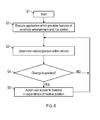
FIG. 6 is a flowchart of a method of controlling operation of a portable user equipment according to various embodiments. - In the drawings, like reference numerals denote like elements. The drawings are to be regarded as schematic representation of embodiments, and elements illustrated in the drawings are not necessarily shown to scale. Rather, the various elements are represented such that their function and general purpose become apparent to a person skilled in the art. Functional blocks or elements may be implemented as hardware, software, firmware, or a combination thereof.
- Hereinafter, various techniques are explained which allow for position-dependent control of a user equipment that is configured to execute an application providing features of in-vehicle entertainment and/or control. Typically, a certain position within the vehicle may be associated with a particular user located at this position. By such means, it is possible to selectively enable or disable user access to at least some of the features in dependence of the particular position of the user equipment and its user within the vehicle (user-dependent access). Certain users may be associated with a particular position within the vehicle; e.g., if the user equipment is located in the front-left side of the vehicle, it may be concluded that the user of the user equipment is the driver of the vehicle; respectively, if the user equipment is positioned in the rear part of the vehicle, it may be concluded that the user of the user equipment is a rear seat passenger. It is then possible to enable or disable user access based on access permissions which are assigned to the respective user associated with the determined position in the vehicle. E.g., due to legal aspects, the driver of the vehicle may only have limited access to entertainment features. Likewise, due to safety reasons, rear seat passengers may only have limited access to vehicle control features.
- In
FIG. 1 , avehicle 100 is illustrated. InFIG. 1 the direction of front movement of thevehicle 100 is illustrated with the full black arrow. A user equipment (UE) 110 is located in the front-right side of thevehicle 100. The respective position 120-2 of theUE 110 is associated with the co-driver of thevehicle 100. TheUE 110 is freely moveable within thevehicle 100 and also outside of thevehicle 100. Other positions hat theUE 110 may assume are associated with the driver 120-1 and the rear-seat passengers 120-3. Further, theUE 110 may assume a position 120-4 outside of thevehicle 100, e.g., close to the doors of the vehicle.. In general, the relative position 120-1 - 120-4 of theUE 110 can be determined within a reference coordinatesystem 150 which is defined with respect to thevehicle 100. While in the scenario ofFIG. 1 the position 120-1 - 120-4 is determined at a comparably low accuracy, respectively high granularity - where it is distinguished only between different seating positions -, it should be understood that, in general, it is also possible that the position 120-1 - 120-4 is determined at a higher accuracy, e.g., on the length scale of centimetres. - Once the relative position 120-1 - 120-4 of the
UE 110 within thevehicle 100 is determined, it becomes possible to provide position-dependent, respectively user-dependent access to features of the respective application executed on theUE 110. E.g., driving related features may be enabled for the driver, i.e., when theUE 110 is located at the respective position 120-1; while such features may be disabled for rear-seat passengers, i.e., when theUE 110 is positioned at the respective position 120-3. - There exist various possibilities of determining the position of the
UE 110. E.g., theUE 110 and / or thevehicle 100 can comprise a positioning unit (not shown inFIG. 1 ) which is configured to determine the relative position 120-1 - 120-4 by determining a signal strength of an electromagnetic field emitted by a transceiver 130-1, 130-2, 130-3 of thevehicle 100. For a larger (smaller) signal strength, it may be concluded that theUE 110 has a smaller (larger) distance to the respective transceiver 130-1 - 130-3. For such purposes, theUE 110 may alternatively or additionally be equipped with a transceiver (not shown inFIG. 1 ). It is also possible that - besides the signal strength-the positioning unit takes into account signal phases of the respective electromagnetic fields emitted by the transceivers 130-1 - 130-3; as shown inFIG. 2 , techniques of triangulation, principally known to a person skilled in the art, may find an application. For this a time-synchronized setup of the transceivers 130-1 - 130-3 may be required. As the transceivers are mounted in different fixed positions within the vehicle, it becomes possible to determine the relative position of theUE 110 within the reference coordinatesystem 150. InFIG.2 , the transceivers 130-1 - 130-3 are situated in substantially opposing solid angles with respect to the UE 110 - this may increase the accuracy in determining the relative position. -
FIG. 3 shows a schematic representation of theUE 110. Shown are thepositioning unit 110b and aprocessor 110a which is configured to execute the application. Further shown is aninterface 110c. Theinterface 110c may establish a wireless and/or fixed-line connection withvehicle 100. E.g., via electrical connectors provided as part of theinterface 110c, a fixed line connection may be established with an inter-related cradle mounted at a fixed position of thevehicle 100. Thepositioning unit 110b can be configured to determine the relative position 120-1 - 120-4 by determining the fixed line connection. E.g., for the various positions 120-1 - 120-4 there may be separate dedicated cradles of thevehicle 100 provided. Then, by connecting theUE 110 with a certain cradle, it may be possible to conclude on the present position of the UE 11). In further scenarios, thepositioning unit 110b can comprise, e.g., an acceleration sensor and can be configured to determine the relative position 120-1 - 120-4 by determining an acceleration of theUE 110 relative to the global acceleration of thevehicle 100. Typically, the acceleration of theUE 110 is a superposition of the global acceleration of thevehicle 100 and theacceleration 110 relative to thevehicle 100 within the reference coordinatesystem 150. - Yet a further scenario of determining the relative position 120-1 - 120-4 is to establish a wireless connection with a NFC transceiver 130-1 - 130-3 of the
vehicle 100. Typically, NFC transceivers 130-1 - 130-3 have a limited range, e.g., on the length scales of a few centimetres. In turn, when a respective wireless communication with a NFC transceiver 130-1 - 130-3 is established, it may be possible to determine the position of theUE 110 at the same length scale. For this, e.g., passive NFC tags may be positioned throughout the vehicle. The NFC tags may have the respective position explicitly or implicitly encoded. In order to gain access to certain features of the application, it may be required that the user brings theUE 110 within the vicinity of such a tag such that the relative position with the reference coordinatesystem 150 may be determined. - Yet a further scenario of determining the relative position 120-1 - 120-4 is to provide optical transceivers 130-1 - 130-3 throughout the
vehicle 100. E.g., the optical transceivers may emit or receive an invisible or visible optical signal. The positingunit 110b of theUE 110 may comprise, e.g., a position-sensitive device which detects such optical signals to determine the relative position 120-1 - 120-4. Additionally or alternatively, it is also possible that theUE 110 emits the visible or invisible optical signals and a position-sensitive device is mounted in the vehicle, i.e., fixed within the reference coordinatesystem 150. In a further scenario, it would be possible that optical cameras mounted within thevehicle 110 monitor the vehicle interior and recognize theUE 110 from image data. Also by such means it is possible to determine the position 120-1 - 120-4 of theUE 110 within thevehicle 100. - In
FIG. 4 , a GUI 200-1 of the application executed by theprocessing unit 110a is shown. The GUI 200-1 is selected if it is determined that theUE 110 is at the co-driver position 120-2 (cf.FIG. 1 ). In particular, the GUI 200-1 offers a number of features 210-1 - 210-6 to the user, i.e., to the co-driver. The features 210-1 - 210-2 relate to entertainment functionality, i.e., to radio and movie playback. The feature 210-3 relates to navigation of the vehicle. The feature 210-4 - which, in the scenario ofFIG. 4 , is shown as currently being activated - relates to in-vehicle climate control. In the scenario ofFIG. 4 , the in-vehicle climate control feature 210-4 allows to set the temperature and the fan speed separately for the front of the vehicle via feature 210-5 and for the rear part of the vehicle via feature 210-6. As a further feature, a current temperature 210-7 is output to the user. - In
FIG. 5 , the GUI 210-2 is shown which is selected if theUE 110 is located in the rear seat passenger position 120-3 (cf.FIG. 1 ). As can be seen from a comparison ofFIGs. 4 and 5 , the features 210-2, 210-3, and 210-5 are disabled. Therefore, if theUE 100 is moved from the position 120-2 of the co-driver to the rear seat passenger position 120-3, the respective user access is dynamically disabled. This may be due to respective access permissions that are assigned to the respective users associated with a determined relative position 120-1 - 120-4. Various scenarios are conceivable on how the access permissions are assigned to the various users associated with the position throughout thevehicle 100 and the respective scenarios are not particularly limited. - In
FIG. 6 , a flowchart illustrates a method of controlling the operation of theUE 110. The method starts with step S1. In step S2, the application is executed which provides features of in-vehicle entertainment and/or control. Next, in step S2, the relative position 120-1 - 120-4 of theUE 110 within the reference coordinatesystem 150, i.e., within thevehicle 100, is determined. In step S3, it is checked whether there is a change in position detected, e.g., if compared to the last determined position. If such a change in position is not detected, e.g., after a certain predefined idle time, step S2 is reexecuted. However, if in step S3 a change in position 120-1 - 120-4 is detected, the method commences with step S4. In step S4, the user access to features 210-1 - 210-6 is adapted in dependence of the new determined relative position 120-1 - 120-4. When executing step S4, it is possible to take into account predefined access permissions assigned to a user associated with a determined relative position 120-1 - 120-4. - Although the invention has been described with respect to certain preferred embodiments, equivalents, combinations and modifications will occur to others skilled in the art upon reading and understand of the specification. The present invention includes all such equivalents, combinations and modifications and it is only limited by the scope of the appended claims.
Claims (15)
- A user equipment (110), comprising:- a positioning unit (110b) configured to determine a relative position (120-1, 120-2, 120-3, 120-4) of the user equipment (110) within a reference coordinate system (150) which is defined with respect to a vehicle (100),- a processing unit (110a) configured to execute an application, the application providing features (210-1 - 210-7) of in-vehicle entertainment and / or control to a user of the user equipment (110),wherein the processing unit (110a) is configured to selectively enable or disable user access to at least some of the features (210-1 - 210-7) of the application in dependence of the determined relative position (120-1, 120-2, 120-3, 120-4).
- The user equipment (110) of claim 1,
wherein the positioning unit (110b) is configured to determine the relative position (120-1, 120-2, 120-3, 120-4) by determining a signal strength of an electromagnetic field emitted by a transceiver (130-1, 130-2, 130-3) of the vehicle (100). - The user equipment (110) of claim 2,
wherein the positioning unit (110b) is configured to determine the relative position (120-1, 120-2, 120-3, 120-4) in dependence of the signal strength of at least two electromagnetic fields emitted by at least two transceivers (130-1, 130-2, 130-3) of the vehicle (100) and further in dependence of signal phases of the at least two electromagnetic fields. - The user equipment (110) of any one of the preceding claims,
wherein the positioning unit (110b) is configured to determine the relative position (120-1, 120-2, 120-3, 120-4) based on control data which is received via a data connection established between the user equipment (110) and a transceiver (130-1, 130-2, 130-3) of the vehicle (100), the control data indicating an occupancy of seating positions of the vehicle (100). - The user equipment (110) of any one of the preceding claims,
wherein the positioning unit (110b) is configured to determine the relative position (120-1, 120-2, 120-3, 120-4) by determining the presence of a fixed line connection between the user equipment (110) and an interface of the vehicle (100). - The user equipment (110) of any one of the preceding claims,
wherein the positioning unit (110b) is configured to determine the relative position (120-1, 120-2, 120-3, 120-4) by determining acceleration of the user equipment (110) relative to acceleration of the vehicle (100). - The user equipment (110) of any one of the preceding claims,
wherein the positioning unit (110b) is configured to determine the relative position (120-1, 120-2, 120-3, 120-4) by establishing a wireless connection with a Near Field Communication transceiver (130-1, 130-2, 130-3) of the vehicle (100). - The user equipment (110) of any one of the preceding claims,
wherein the positioning unit (110b) is configured to determine the relative position (120-1, 120-2, 120-3, 120-4) by receiving invisible or visible optical signals from a transceiver (130-1, 130-2, 130-3) of the vehicle (100). - The user equipment (110) of any one of the preceding claims,
wherein the processing unit (110a) is further configured to select a graphical user interface (200-1, 200-2) of the application in dependence of the relative position (120-1, 120-2, 120-3, 120-4). - The user equipment (110) of any one of the preceding claims,
wherein the processing unit (110a) is configured to selectively enable or disable user access to at least some of the features (210-1 - 210-7) of the application in dependence of access permissions assigned to a user associated with the determined relative position (120-1, 120-2, 120-3, 120-4). - The user equipment (110) of claim 10,
wherein the access permissions of a user located in the driver seat of the vehicle (100) cover features (210-1 - 210-7) selected from the group comprising:- features relevant for navigation of the vehicle (100) such as route planning, route guidance, and range estimation;- features relevant for traffic awareness such as traffic messages, detour planning, traffic delays;- features relevant for vehicle and passenger safety such as emergency functions, locking of doors, panic button;- features relevant for vehicle control such as in-vehicle climate control, engine and gear control, lighting control;- features relevant for communication such as call setup and internet access. - The user equipment (110) of claims 10 or 11,
wherein the access permission of a user located in a rear seat of the vehicle (100) cover features (210-1 - 210-7) selected from the group comprising:- features relevant for rear-seat entertainment;- features relevant for communication such as call setup and internet access. - The user equipment (110) of any one of claims 10 - 12,
wherein the access permissions of a user located outside the vehicle (100) cover features selected form the group comprising:- vehicle access such as locking and unlocking of doors, opening and closing of doors, and emergency lock down;- in-vehicle climate control such as park heating. - The user equipment (110) of any one of the preceding claims,
wherein the positioning unit (110b) is configured to determine the relative position (120-1, 120-2, 120-3, 120-4) in terms of seating positions of the vehicle (100). - A method of controlling operation of a user equipment (110), the user equipment (110) being positioned in a reference coordinate system (150) which is defined with respect to a vehicle (100),
the method comprising:- a positioning unit (110b) determining a relative position (120-1, 120-2, 120-3, 120-4) of the user equipment (110) within the reference coordinate system (150),- a processing unit (110a) executing an application, the application providing features (210-1 - 210-7) of in-vehicle entertainment and / or control to a user of the user equipment (110),- the processing unit (110a) selectively enabling or disabling access to at least some of the features (210-1 - 210-7) of the application in dependence of the determined relative position (120-1, 120-2, 120-3, 120-4).
Priority Applications (2)
| Application Number | Priority Date | Filing Date | Title |
|---|---|---|---|
| EP14172794.1A EP2958349B1 (en) | 2014-06-17 | 2014-06-17 | Control of a user equipment based on in-vehicle position |
| US14/733,868 US9533576B2 (en) | 2014-06-17 | 2015-06-08 | Control of a user equipment based on in-vehicle position |
Applications Claiming Priority (1)
| Application Number | Priority Date | Filing Date | Title |
|---|---|---|---|
| EP14172794.1A EP2958349B1 (en) | 2014-06-17 | 2014-06-17 | Control of a user equipment based on in-vehicle position |
Publications (2)
| Publication Number | Publication Date |
|---|---|
| EP2958349A1 true EP2958349A1 (en) | 2015-12-23 |
| EP2958349B1 EP2958349B1 (en) | 2017-02-01 |
Family
ID=50980939
Family Applications (1)
| Application Number | Title | Priority Date | Filing Date |
|---|---|---|---|
| EP14172794.1A Active EP2958349B1 (en) | 2014-06-17 | 2014-06-17 | Control of a user equipment based on in-vehicle position |
Country Status (2)
| Country | Link |
|---|---|
| US (1) | US9533576B2 (en) |
| EP (1) | EP2958349B1 (en) |
Cited By (2)
| Publication number | Priority date | Publication date | Assignee | Title |
|---|---|---|---|---|
| DE102016216562A1 (en) | 2016-09-01 | 2018-03-01 | Continental Automotive Gmbh | Method and device for locating a mobile terminal, in particular in the form of a mobile station for a particular cellular mobile network by a device on the part of a motor vehicle |
| DE102018111408A1 (en) * | 2018-05-14 | 2019-11-14 | Hochschule Für Technik Und Wirtschaft Berlin | Method for operating a mobile telephone in a vehicle |
Families Citing this family (16)
| Publication number | Priority date | Publication date | Assignee | Title |
|---|---|---|---|---|
| GB2545005B (en) * | 2015-12-03 | 2021-09-08 | Bentley Motors Ltd | Responsive human machine interface |
| US9775100B1 (en) * | 2016-03-22 | 2017-09-26 | Livio, Inc. | Passenger zone detection with signal strength data aided by physical signal barriers |
| US11391810B2 (en) * | 2016-08-31 | 2022-07-19 | Ford Global Technologies, Llc | Method and apparatus for vehicle occupant location detection |
| US10230834B2 (en) | 2017-02-27 | 2019-03-12 | Jonathan William Bachmann | Applications, methods, and systems for preventing a mobile device user from operating functions of a mobile device while operating a motor vehicle |
| DE102017206119A1 (en) * | 2017-04-10 | 2018-10-11 | Bayerische Motoren Werke Aktiengesellschaft | A method, computer readable medium, system, and vehicle comprising the system for determining a location range of a mobile terminal relative to the vehicle |
| JP2019009724A (en) * | 2017-06-28 | 2019-01-17 | 矢崎総業株式会社 | Wireless communication system for vehicles |
| US11188152B2 (en) * | 2017-07-05 | 2021-11-30 | Mitsubishi Electric Corporation | Operation unit control device and operation unit control method |
| US11743806B2 (en) * | 2017-12-05 | 2023-08-29 | Ford Global Technologies, Llc | Method and apparatus for wireless communication suppression |
| US20190053022A1 (en) * | 2017-12-27 | 2019-02-14 | Intel Corporation | Provision of in-vehicle service to a mobile device |
| US11180158B1 (en) * | 2018-07-31 | 2021-11-23 | United Services Automobile Association (Usaa) | Routing or driving systems and methods based on sleep pattern information |
| JP7183830B2 (en) * | 2019-01-31 | 2022-12-06 | 株式会社Soken | Vehicle localization system |
| US11194008B2 (en) | 2019-10-25 | 2021-12-07 | Toyota Motor Engineering And Manufacturing North America, Inc. | Triangulation and calibration of electronic control units |
| US11917094B2 (en) * | 2021-02-01 | 2024-02-27 | Aptiv Technologies Limited | Automatic control of smartphone driver mode using ultra-wideband communication |
| US12570149B2 (en) * | 2023-05-12 | 2026-03-10 | Adeia Guides Inc. | User interface method and apparatus for vehicle display |
| EP4600066A1 (en) * | 2024-02-08 | 2025-08-13 | Valeo Comfort and Driving Assistance | Method and system for controlling a human-machine interface in a vehicle |
| US20260086244A1 (en) * | 2024-09-25 | 2026-03-26 | Zoox, Inc. | Wayfinding using direct wireless interface |
Citations (2)
| Publication number | Priority date | Publication date | Assignee | Title |
|---|---|---|---|---|
| US20110295458A1 (en) * | 2010-05-28 | 2011-12-01 | Verizon Virginia | Systems and Methods for Selectively Disabling One or More Features of a Mobile Access Device and/or a Vehicle Associated with the Mobile Access Device |
| US20120129544A1 (en) * | 2010-11-19 | 2012-05-24 | Illume Software, Inc. | Systems and methods for selectively invoking positioning systems for mobile device control applications using accelerometer measurements |
Family Cites Families (8)
| Publication number | Priority date | Publication date | Assignee | Title |
|---|---|---|---|---|
| US20130150004A1 (en) * | 2006-08-11 | 2013-06-13 | Michael Rosen | Method and apparatus for reducing mobile phone usage while driving |
| US8213962B2 (en) * | 2009-07-21 | 2012-07-03 | Verizon Patent And Licensing Inc. | Vehicle computer link to mobile phone |
| US8315617B2 (en) * | 2009-10-31 | 2012-11-20 | Btpatent Llc | Controlling mobile device functions |
| US8874162B2 (en) * | 2011-12-23 | 2014-10-28 | Microsoft Corporation | Mobile device safe driving |
| US8538402B2 (en) * | 2012-02-12 | 2013-09-17 | Joel Vidal | Phone that prevents texting while driving |
| EP2815593A4 (en) * | 2012-02-17 | 2015-08-12 | Intertrust Tech Corp | Systems and methods for vehicle policy enforcement |
| US20140015683A1 (en) * | 2012-07-11 | 2014-01-16 | Manjunath Bharadwaj Subramanya | Deterring electronic device usage under unsuitable conditions |
| US9198113B2 (en) * | 2013-03-15 | 2015-11-24 | Aswin Rajeevalochana | App for preventing phone functionality while driving |
-
2014
- 2014-06-17 EP EP14172794.1A patent/EP2958349B1/en active Active
-
2015
- 2015-06-08 US US14/733,868 patent/US9533576B2/en active Active
Patent Citations (2)
| Publication number | Priority date | Publication date | Assignee | Title |
|---|---|---|---|---|
| US20110295458A1 (en) * | 2010-05-28 | 2011-12-01 | Verizon Virginia | Systems and Methods for Selectively Disabling One or More Features of a Mobile Access Device and/or a Vehicle Associated with the Mobile Access Device |
| US20120129544A1 (en) * | 2010-11-19 | 2012-05-24 | Illume Software, Inc. | Systems and methods for selectively invoking positioning systems for mobile device control applications using accelerometer measurements |
Cited By (4)
| Publication number | Priority date | Publication date | Assignee | Title |
|---|---|---|---|---|
| DE102016216562A1 (en) | 2016-09-01 | 2018-03-01 | Continental Automotive Gmbh | Method and device for locating a mobile terminal, in particular in the form of a mobile station for a particular cellular mobile network by a device on the part of a motor vehicle |
| US10616855B2 (en) | 2016-09-01 | 2020-04-07 | Continental Automotive Gmbh | Method and apparatus for locating a mobile terminal |
| DE102016216562B4 (en) | 2016-09-01 | 2021-08-12 | Continental Automotive Gmbh | Method and device for locating a mobile terminal, in particular in the form of a mobile radio terminal for an in particular cellular mobile radio network, by a device on the part of a motor vehicle |
| DE102018111408A1 (en) * | 2018-05-14 | 2019-11-14 | Hochschule Für Technik Und Wirtschaft Berlin | Method for operating a mobile telephone in a vehicle |
Also Published As
| Publication number | Publication date |
|---|---|
| EP2958349B1 (en) | 2017-02-01 |
| US20150360564A1 (en) | 2015-12-17 |
| US9533576B2 (en) | 2017-01-03 |
Similar Documents
| Publication | Publication Date | Title |
|---|---|---|
| EP2958349B1 (en) | Control of a user equipment based on in-vehicle position | |
| KR101876010B1 (en) | System and method for determining smartphone location | |
| EP2964479B1 (en) | Method and mobile device for preventing driver distraction | |
| US9751497B2 (en) | Vehicle control apparatus | |
| CN107054290B (en) | Personal device location authentication for secure functionality access | |
| KR101637670B1 (en) | System for recognizing passenger and boarding position in vehicle | |
| US9860710B2 (en) | Symmetrical reference personal device location tracking | |
| US9386136B2 (en) | Automatic device initialization and pairing | |
| US20130015947A1 (en) | Method and system for access authorization | |
| US20170103592A1 (en) | Automated door and gate lock/unlock | |
| US10134271B1 (en) | Vehicle integration with security and/or automation systems | |
| US20150149042A1 (en) | System and method for configuring an interior of a vehicle based on preferences provided with multiple mobile computing devices within the vehicle | |
| EP3466018B1 (en) | Systems and methods for averting unsanctioned access to on-board vehicle networks | |
| CN107521434A (en) | Method and apparatus for the detection of automotive occupant position | |
| WO2016002131A1 (en) | Portable device and position detection system | |
| WO2015077662A1 (en) | System and method for configuring an interior of a vehicle based on preferences provided with multiple mobile computing devices within the vehicle | |
| JP2019059405A (en) | Terminal, vehicle control system, and vehicle control method | |
| US11157758B2 (en) | System and method to restrict device access in vehicles | |
| JP2015134556A (en) | In-vehicle device and method for suppressing operation in in-vehicle device | |
| US10530890B2 (en) | Method for assigning a user profile of a user to a seat in a motor vehicle, mobile unit and motor vehicle | |
| KR20180095223A (en) | Method for visualization of IoT connection information in autonomous vehicle | |
| KR20160121175A (en) | Apparatus for door lock, system and method for controlling door lock using the same | |
| KR101884562B1 (en) | Device, method and computer program for forming groups of appliances through positioning | |
| HK40080866B (en) | Systems and methods for averting unsanctioned access to on-board vehicle networks | |
| CN118102294A (en) | A method and device for logging into a smart cockpit system |
Legal Events
| Date | Code | Title | Description |
|---|---|---|---|
| PUAI | Public reference made under article 153(3) epc to a published international application that has entered the european phase |
Free format text: ORIGINAL CODE: 0009012 |
|
| AK | Designated contracting states |
Kind code of ref document: A1 Designated state(s): AL AT BE BG CH CY CZ DE DK EE ES FI FR GB GR HR HU IE IS IT LI LT LU LV MC MK MT NL NO PL PT RO RS SE SI SK SM TR |
|
| AX | Request for extension of the european patent |
Extension state: BA ME |
|
| 17P | Request for examination filed |
Effective date: 20160623 |
|
| RBV | Designated contracting states (corrected) |
Designated state(s): AL AT BE BG CH CY CZ DE DK EE ES FI FR GB GR HR HU IE IS IT LI LT LU LV MC MK MT NL NO PL PT RO RS SE SI SK SM TR |
|
| RIC1 | Information provided on ipc code assigned before grant |
Ipc: G01C 21/34 20060101ALI20160725BHEP Ipc: B60K 35/00 20060101ALI20160725BHEP Ipc: H04W 4/04 20090101AFI20160725BHEP |
|
| GRAP | Despatch of communication of intention to grant a patent |
Free format text: ORIGINAL CODE: EPIDOSNIGR1 |
|
| INTG | Intention to grant announced |
Effective date: 20160915 |
|
| GRAS | Grant fee paid |
Free format text: ORIGINAL CODE: EPIDOSNIGR3 |
|
| GRAA | (expected) grant |
Free format text: ORIGINAL CODE: 0009210 |
|
| AK | Designated contracting states |
Kind code of ref document: B1 Designated state(s): AL AT BE BG CH CY CZ DE DK EE ES FI FR GB GR HR HU IE IS IT LI LT LU LV MC MK MT NL NO PL PT RO RS SE SI SK SM TR |
|
| REG | Reference to a national code |
Ref country code: GB Ref legal event code: FG4D |
|
| REG | Reference to a national code |
Ref country code: CH Ref legal event code: EP Ref country code: AT Ref legal event code: REF Ref document number: 866397 Country of ref document: AT Kind code of ref document: T Effective date: 20170215 |
|
| REG | Reference to a national code |
Ref country code: IE Ref legal event code: FG4D |
|
| REG | Reference to a national code |
Ref country code: DE Ref legal event code: R096 Ref document number: 602014006486 Country of ref document: DE |
|
| REG | Reference to a national code |
Ref country code: NL Ref legal event code: MP Effective date: 20170201 |
|
| REG | Reference to a national code |
Ref country code: LT Ref legal event code: MG4D |
|
| REG | Reference to a national code |
Ref country code: AT Ref legal event code: MK05 Ref document number: 866397 Country of ref document: AT Kind code of ref document: T Effective date: 20170201 |
|
| PG25 | Lapsed in a contracting state [announced via postgrant information from national office to epo] |
Ref country code: NO Free format text: LAPSE BECAUSE OF FAILURE TO SUBMIT A TRANSLATION OF THE DESCRIPTION OR TO PAY THE FEE WITHIN THE PRESCRIBED TIME-LIMIT Effective date: 20170501 Ref country code: LT Free format text: LAPSE BECAUSE OF FAILURE TO SUBMIT A TRANSLATION OF THE DESCRIPTION OR TO PAY THE FEE WITHIN THE PRESCRIBED TIME-LIMIT Effective date: 20170201 Ref country code: GR Free format text: LAPSE BECAUSE OF FAILURE TO SUBMIT A TRANSLATION OF THE DESCRIPTION OR TO PAY THE FEE WITHIN THE PRESCRIBED TIME-LIMIT Effective date: 20170502 Ref country code: IS Free format text: LAPSE BECAUSE OF FAILURE TO SUBMIT A TRANSLATION OF THE DESCRIPTION OR TO PAY THE FEE WITHIN THE PRESCRIBED TIME-LIMIT Effective date: 20170601 Ref country code: FI Free format text: LAPSE BECAUSE OF FAILURE TO SUBMIT A TRANSLATION OF THE DESCRIPTION OR TO PAY THE FEE WITHIN THE PRESCRIBED TIME-LIMIT Effective date: 20170201 Ref country code: HR Free format text: LAPSE BECAUSE OF FAILURE TO SUBMIT A TRANSLATION OF THE DESCRIPTION OR TO PAY THE FEE WITHIN THE PRESCRIBED TIME-LIMIT Effective date: 20170201 |
|
| PG25 | Lapsed in a contracting state [announced via postgrant information from national office to epo] |
Ref country code: AT Free format text: LAPSE BECAUSE OF FAILURE TO SUBMIT A TRANSLATION OF THE DESCRIPTION OR TO PAY THE FEE WITHIN THE PRESCRIBED TIME-LIMIT Effective date: 20170201 Ref country code: PT Free format text: LAPSE BECAUSE OF FAILURE TO SUBMIT A TRANSLATION OF THE DESCRIPTION OR TO PAY THE FEE WITHIN THE PRESCRIBED TIME-LIMIT Effective date: 20170601 Ref country code: LV Free format text: LAPSE BECAUSE OF FAILURE TO SUBMIT A TRANSLATION OF THE DESCRIPTION OR TO PAY THE FEE WITHIN THE PRESCRIBED TIME-LIMIT Effective date: 20170201 Ref country code: SE Free format text: LAPSE BECAUSE OF FAILURE TO SUBMIT A TRANSLATION OF THE DESCRIPTION OR TO PAY THE FEE WITHIN THE PRESCRIBED TIME-LIMIT Effective date: 20170201 Ref country code: BG Free format text: LAPSE BECAUSE OF FAILURE TO SUBMIT A TRANSLATION OF THE DESCRIPTION OR TO PAY THE FEE WITHIN THE PRESCRIBED TIME-LIMIT Effective date: 20170501 Ref country code: ES Free format text: LAPSE BECAUSE OF FAILURE TO SUBMIT A TRANSLATION OF THE DESCRIPTION OR TO PAY THE FEE WITHIN THE PRESCRIBED TIME-LIMIT Effective date: 20170201 Ref country code: RS Free format text: LAPSE BECAUSE OF FAILURE TO SUBMIT A TRANSLATION OF THE DESCRIPTION OR TO PAY THE FEE WITHIN THE PRESCRIBED TIME-LIMIT Effective date: 20170201 Ref country code: NL Free format text: LAPSE BECAUSE OF NON-PAYMENT OF DUE FEES Effective date: 20170201 Ref country code: PL Free format text: LAPSE BECAUSE OF FAILURE TO SUBMIT A TRANSLATION OF THE DESCRIPTION OR TO PAY THE FEE WITHIN THE PRESCRIBED TIME-LIMIT Effective date: 20170201 |
|
| PG25 | Lapsed in a contracting state [announced via postgrant information from national office to epo] |
Ref country code: SK Free format text: LAPSE BECAUSE OF FAILURE TO SUBMIT A TRANSLATION OF THE DESCRIPTION OR TO PAY THE FEE WITHIN THE PRESCRIBED TIME-LIMIT Effective date: 20170201 Ref country code: IT Free format text: LAPSE BECAUSE OF FAILURE TO SUBMIT A TRANSLATION OF THE DESCRIPTION OR TO PAY THE FEE WITHIN THE PRESCRIBED TIME-LIMIT Effective date: 20170201 Ref country code: RO Free format text: LAPSE BECAUSE OF FAILURE TO SUBMIT A TRANSLATION OF THE DESCRIPTION OR TO PAY THE FEE WITHIN THE PRESCRIBED TIME-LIMIT Effective date: 20170201 Ref country code: CZ Free format text: LAPSE BECAUSE OF FAILURE TO SUBMIT A TRANSLATION OF THE DESCRIPTION OR TO PAY THE FEE WITHIN THE PRESCRIBED TIME-LIMIT Effective date: 20170201 Ref country code: EE Free format text: LAPSE BECAUSE OF FAILURE TO SUBMIT A TRANSLATION OF THE DESCRIPTION OR TO PAY THE FEE WITHIN THE PRESCRIBED TIME-LIMIT Effective date: 20170201 |
|
| REG | Reference to a national code |
Ref country code: DE Ref legal event code: R097 Ref document number: 602014006486 Country of ref document: DE |
|
| REG | Reference to a national code |
Ref country code: DE Ref legal event code: R079 Ref document number: 602014006486 Country of ref document: DE Free format text: PREVIOUS MAIN CLASS: H04W0004040000 Ipc: H04W0004300000 |
|
| PG25 | Lapsed in a contracting state [announced via postgrant information from national office to epo] |
Ref country code: DK Free format text: LAPSE BECAUSE OF FAILURE TO SUBMIT A TRANSLATION OF THE DESCRIPTION OR TO PAY THE FEE WITHIN THE PRESCRIBED TIME-LIMIT Effective date: 20170201 Ref country code: SM Free format text: LAPSE BECAUSE OF FAILURE TO SUBMIT A TRANSLATION OF THE DESCRIPTION OR TO PAY THE FEE WITHIN THE PRESCRIBED TIME-LIMIT Effective date: 20170201 |
|
| PLBE | No opposition filed within time limit |
Free format text: ORIGINAL CODE: 0009261 |
|
| STAA | Information on the status of an ep patent application or granted ep patent |
Free format text: STATUS: NO OPPOSITION FILED WITHIN TIME LIMIT |
|
| 26N | No opposition filed |
Effective date: 20171103 |
|
| PG25 | Lapsed in a contracting state [announced via postgrant information from national office to epo] |
Ref country code: MC Free format text: LAPSE BECAUSE OF FAILURE TO SUBMIT A TRANSLATION OF THE DESCRIPTION OR TO PAY THE FEE WITHIN THE PRESCRIBED TIME-LIMIT Effective date: 20170201 |
|
| REG | Reference to a national code |
Ref country code: CH Ref legal event code: PL |
|
| PG25 | Lapsed in a contracting state [announced via postgrant information from national office to epo] |
Ref country code: SI Free format text: LAPSE BECAUSE OF FAILURE TO SUBMIT A TRANSLATION OF THE DESCRIPTION OR TO PAY THE FEE WITHIN THE PRESCRIBED TIME-LIMIT Effective date: 20170201 |
|
| REG | Reference to a national code |
Ref country code: IE Ref legal event code: MM4A |
|
| REG | Reference to a national code |
Ref country code: FR Ref legal event code: ST Effective date: 20180228 |
|
| PG25 | Lapsed in a contracting state [announced via postgrant information from national office to epo] |
Ref country code: LU Free format text: LAPSE BECAUSE OF NON-PAYMENT OF DUE FEES Effective date: 20170617 Ref country code: IE Free format text: LAPSE BECAUSE OF NON-PAYMENT OF DUE FEES Effective date: 20170617 Ref country code: LI Free format text: LAPSE BECAUSE OF NON-PAYMENT OF DUE FEES Effective date: 20170630 Ref country code: CH Free format text: LAPSE BECAUSE OF NON-PAYMENT OF DUE FEES Effective date: 20170630 |
|
| PG25 | Lapsed in a contracting state [announced via postgrant information from national office to epo] |
Ref country code: FR Free format text: LAPSE BECAUSE OF NON-PAYMENT OF DUE FEES Effective date: 20170630 |
|
| REG | Reference to a national code |
Ref country code: BE Ref legal event code: MM Effective date: 20170630 |
|
| PG25 | Lapsed in a contracting state [announced via postgrant information from national office to epo] |
Ref country code: BE Free format text: LAPSE BECAUSE OF NON-PAYMENT OF DUE FEES Effective date: 20170630 |
|
| PG25 | Lapsed in a contracting state [announced via postgrant information from national office to epo] |
Ref country code: MT Free format text: LAPSE BECAUSE OF NON-PAYMENT OF DUE FEES Effective date: 20170617 |
|
| PG25 | Lapsed in a contracting state [announced via postgrant information from national office to epo] |
Ref country code: HU Free format text: LAPSE BECAUSE OF FAILURE TO SUBMIT A TRANSLATION OF THE DESCRIPTION OR TO PAY THE FEE WITHIN THE PRESCRIBED TIME-LIMIT; INVALID AB INITIO Effective date: 20140617 |
|
| PG25 | Lapsed in a contracting state [announced via postgrant information from national office to epo] |
Ref country code: CY Free format text: LAPSE BECAUSE OF FAILURE TO SUBMIT A TRANSLATION OF THE DESCRIPTION OR TO PAY THE FEE WITHIN THE PRESCRIBED TIME-LIMIT Effective date: 20170201 |
|
| PG25 | Lapsed in a contracting state [announced via postgrant information from national office to epo] |
Ref country code: MK Free format text: LAPSE BECAUSE OF FAILURE TO SUBMIT A TRANSLATION OF THE DESCRIPTION OR TO PAY THE FEE WITHIN THE PRESCRIBED TIME-LIMIT Effective date: 20170201 |
|
| PG25 | Lapsed in a contracting state [announced via postgrant information from national office to epo] |
Ref country code: TR Free format text: LAPSE BECAUSE OF FAILURE TO SUBMIT A TRANSLATION OF THE DESCRIPTION OR TO PAY THE FEE WITHIN THE PRESCRIBED TIME-LIMIT Effective date: 20170201 |
|
| PG25 | Lapsed in a contracting state [announced via postgrant information from national office to epo] |
Ref country code: AL Free format text: LAPSE BECAUSE OF FAILURE TO SUBMIT A TRANSLATION OF THE DESCRIPTION OR TO PAY THE FEE WITHIN THE PRESCRIBED TIME-LIMIT Effective date: 20170201 |
|
| P01 | Opt-out of the competence of the unified patent court (upc) registered |
Effective date: 20230526 |
|
| PGFP | Annual fee paid to national office [announced via postgrant information from national office to epo] |
Ref country code: DE Payment date: 20250520 Year of fee payment: 12 |
|
| PGFP | Annual fee paid to national office [announced via postgrant information from national office to epo] |
Ref country code: GB Payment date: 20250520 Year of fee payment: 12 |