EP2958199A1 - Power adaptor with retractable prongs - Google Patents
Power adaptor with retractable prongs Download PDFInfo
- Publication number
- EP2958199A1 EP2958199A1 EP15169436.1A EP15169436A EP2958199A1 EP 2958199 A1 EP2958199 A1 EP 2958199A1 EP 15169436 A EP15169436 A EP 15169436A EP 2958199 A1 EP2958199 A1 EP 2958199A1
- Authority
- EP
- European Patent Office
- Prior art keywords
- retractable
- housing
- prong
- power adapter
- rotatable shaft
- Prior art date
- Legal status (The legal status is an assumption and is not a legal conclusion. Google has not performed a legal analysis and makes no representation as to the accuracy of the status listed.)
- Granted
Links
Images



Classifications
-
- H—ELECTRICITY
- H01—ELECTRIC ELEMENTS
- H01R—ELECTRICALLY-CONDUCTIVE CONNECTIONS; STRUCTURAL ASSOCIATIONS OF A PLURALITY OF MUTUALLY-INSULATED ELECTRICAL CONNECTING ELEMENTS; COUPLING DEVICES; CURRENT COLLECTORS
- H01R13/00—Details of coupling devices of the kinds covered by groups H01R12/70 or H01R24/00 - H01R33/00
- H01R13/40—Securing contact members in or to a base or case; Insulating of contact members
-
- H—ELECTRICITY
- H01—ELECTRIC ELEMENTS
- H01R—ELECTRICALLY-CONDUCTIVE CONNECTIONS; STRUCTURAL ASSOCIATIONS OF A PLURALITY OF MUTUALLY-INSULATED ELECTRICAL CONNECTING ELEMENTS; COUPLING DEVICES; CURRENT COLLECTORS
- H01R24/00—Two-part coupling devices, or either of their cooperating parts, characterised by their overall structure
- H01R24/66—Two-part coupling devices, or either of their cooperating parts, characterised by their overall structure with pins, blades or analogous contacts and secured to apparatus or structure, e.g. to a wall
- H01R24/68—Two-part coupling devices, or either of their cooperating parts, characterised by their overall structure with pins, blades or analogous contacts and secured to apparatus or structure, e.g. to a wall mounted on directly pluggable apparatus
-
- H—ELECTRICITY
- H01—ELECTRIC ELEMENTS
- H01R—ELECTRICALLY-CONDUCTIVE CONNECTIONS; STRUCTURAL ASSOCIATIONS OF A PLURALITY OF MUTUALLY-INSULATED ELECTRICAL CONNECTING ELEMENTS; COUPLING DEVICES; CURRENT COLLECTORS
- H01R13/00—Details of coupling devices of the kinds covered by groups H01R12/70 or H01R24/00 - H01R33/00
- H01R13/40—Securing contact members in or to a base or case; Insulating of contact members
- H01R13/42—Securing in a demountable manner
- H01R13/428—Securing in a demountable manner by resilient locking means on the contact members; by locking means on resilient contact members
- H01R13/434—Securing in a demountable manner by resilient locking means on the contact members; by locking means on resilient contact members by separate resilient locking means on contact member, e.g. retainer collar or ring around contact member
-
- H—ELECTRICITY
- H01—ELECTRIC ELEMENTS
- H01R—ELECTRICALLY-CONDUCTIVE CONNECTIONS; STRUCTURAL ASSOCIATIONS OF A PLURALITY OF MUTUALLY-INSULATED ELECTRICAL CONNECTING ELEMENTS; COUPLING DEVICES; CURRENT COLLECTORS
- H01R24/00—Two-part coupling devices, or either of their cooperating parts, characterised by their overall structure
- H01R24/28—Coupling parts carrying pins, blades or analogous contacts and secured only to wire or cable
- H01R24/30—Coupling parts carrying pins, blades or analogous contacts and secured only to wire or cable with additional earth or shield contacts
-
- H—ELECTRICITY
- H01—ELECTRIC ELEMENTS
- H01R—ELECTRICALLY-CONDUCTIVE CONNECTIONS; STRUCTURAL ASSOCIATIONS OF A PLURALITY OF MUTUALLY-INSULATED ELECTRICAL CONNECTING ELEMENTS; COUPLING DEVICES; CURRENT COLLECTORS
- H01R13/00—Details of coupling devices of the kinds covered by groups H01R12/70 or H01R24/00 - H01R33/00
- H01R13/02—Contact members
- H01R13/04—Pins or blades for co-operation with sockets
- H01R13/05—Resilient pins or blades
- H01R13/055—Resilient pins or blades co-operating with sockets having a rectangular transverse section
-
- H—ELECTRICITY
- H01—ELECTRIC ELEMENTS
- H01R—ELECTRICALLY-CONDUCTIVE CONNECTIONS; STRUCTURAL ASSOCIATIONS OF A PLURALITY OF MUTUALLY-INSULATED ELECTRICAL CONNECTING ELEMENTS; COUPLING DEVICES; CURRENT COLLECTORS
- H01R2103/00—Two poles
Definitions
- pivot point 198 for line and neutral retractable prongs 105 is proximate a first end 180 of line and neutral slots 115 while pivot point 199 for earth prong 110 is proximate an end of earth slot 120 opposite the first end 180 of the line and neutral slots.
- line and neutral prongs 105 may pivot in an opposite direction as ground prong 110. More specifically, as illustrated in FIG. 2 , when transitioning from the deployed position to the retracted position, line and neutral prongs 105 may pivot up while ground prong 110 may pivot down.
- actuation mechanism 440 may cause first and second retractable prongs 405, 415, respectively to self-actuate (i.e., "snap") to the retracted position.
- self-actuate shall mean that the mechanism is relatively unstable between the first and second detent positions such that when it is in-between the two detent positions it will self-actuate (i.e., move under its own power) towards one or the other points of equilibrium.
- tension spring 445 may be stretched more when in between the retracted and deployed positions such that first and second retractable prongs 405, 415, respectively will be relatively unstable between the retracted and deployed positions and will self-actuate between the two positions, forcing the first and second retractable prongs against the hard stops.
- First hub pin 470 may be axially offset from first rotatable shaft 410 axis of rotation such that first portion 430 of linkage 425 does not interfere with the first rotatable shaft when transitioning between the retracted and the deployed positions.
- second hub pin 480 may be axially offset from second rotatable shaft 420 axis of rotation such that second portion 435 of linkage 425 does not interfere with the second rotatable shaft when transitioning between the retracted and the deployed positions.
- the four linkage members are the housing that is disposed between first rotatable shaft 410 and second rotatable shaft 420, the offset between first rotatable shaft 410 and first hub pin 470, the offset between second rotatable shaft 420 and second hub pin 480, and linkage 425.
- Some embodiments and configurations of the power adapters disclosed herein may include either a linkage or an actuation mechanism, or both. Further, some embodiments may employ different linkage and/or actuation mechanisms than those illustrated herein. The different linkage and actuation mechanisms may be used interchangeably and in different combinations as discussed in more detail below.
- First retractable prong 705 is coupled to a first rotatable shaft (not shown) within housing 702 such that the first retractable prong can be pivoted from a retracted position in which the first retractable prong is positioned adjacent to the housing, to a deployed position in which the first retractable prong extends away from the housing, and can be inserted into an electrical outlet.
- second retractable prong 715 may comprise two adjacent prongs.
- first crank 750 and second crank 755 may rotate approximately 90 degrees between the retracted position and the deployed position.
- First pin 770 may be axially offset from first rotatable shaft (not shown) such that first portion 730 of linkage 725 does not interfere with the first rotatable shaft when transitioning between the retracted and the deployed positions.
- Power adapter 900 includes a first retractable prong 905 and a pair of second retractable prongs 915 (only one of which is shown in FIGS. 9-10 ).
- Housing 902 can be similar to housing 102 shown in FIGS. 1-3 and may include slots (not shown in FIGS. 4-6 ) similar to slots 115, 120 to hide prongs 905, 915 in a retracted position as shown in FIGS. 1-3 .
- First retractable prong 905 is coupled to a first rotatable shaft (not shown) within housing 902 such that the first retractable prong can be pivoted from a retracted position in which the first retractable prong is positioned adjacent to the housing, to a deployed position in which the first retractable prong extends away from the housing, and can be inserted into an electrical outlet.
- second retractable prong 915 may comprise two adjacent prongs.
- Second retractable prong 915 is coupled to a second rotatable shaft (not shown) within housing 902 such that the second retractable prong can be pivoted from a retracted position in which the second retractable prong is positioned adjacent to the housing, to a deployed position in which the second retractable prong extends away from the housing, and can be inserted into an electrical outlet.
- Linkage 925 has a first portion 930 connected to first rotatable shaft (not shown) and second portion 935 connected to second rotatable shaft (not shown) and transfers force such that when first retractable prong 905 is pivoted from the retracted position to the deployed position, second retractable prong 915 is simultaneously pivoted from the retracted position to the deployed position.
- linkage 925 is a pin and slot type with a dual-bar configuration such that it may be attached to a pair of second retractable prongs 915. More specifically, there may be two linkages 925 such that two second retractable prongs 915 may be actuated.
- other types of linkages are within the scope of this disclosure and may be employed in other embodiments.
- First portion 930 of linkage 925 may be coupled to first rotatable shaft (not shown) with a first pin 970 on a first crank 950.
- First pin 970 may be disposed in first slot 990 of linkage 925.
- second portion 935 of linkage 925 may be coupled to second rotatable shaft (not shown) with a second pin 980 on a second crank 955.
- Second pin 980 may be disposed in second slot 995 of linkage 925.
- first crank 950 and second crank 955 may rotate approximately 90 degrees between the retracted position and the deployed position.
- linkage 925 may be in a first position (shown in FIG.
- linkage 925 may be in a second position (shown in FIG. 10 as a "right-most” position) where first and second pins 970, 980, respectively slide in first and second slots, 990, 995, respectively forcing first and second retractable prongs 905, 915, respectively to be in a retracted position.
- linkage 925 may have one or more guides that maintain the linkage in an approximately vertical alignment and don't allow the beam to rotate in plane, as it's illustrated in FIGS 9 and 10 . More specifically, in some embodiments linkage 925 may be constrained to left and right translation only.
- Power adapter 1100 includes a first retractable prong 1105 and a pair of second retractable prongs 1115 (only one of which is shown in FIGS. 11-12 ).
- Housing 1102 can be similar to housing 102 shown in FIGS. 1-3 and may include slots (not shown in FIGS. 11-12 ) similar to slots 115, 120 to hide prongs 1105, 1115 in a retracted position as shown in FIGS. 1-3 .
- First retractable prong 1105 is coupled to a first rotatable shaft 1110 within housing 1102 such that the first retractable prong can be pivoted from a retracted position in which the first retractable prong is positioned adjacent to the housing, to a deployed position in which the first retractable prong extends away from the housing, and can be inserted into an electrical outlet.
- second retractable prong 1115 may comprise two adjacent prongs.
- Second retractable prong 1115 is coupled to a second rotatable shaft 1120 within housing 1102 such that the second retractable prong can be pivoted from a retracted position in which the second retractable prong is positioned adjacent to the housing, to a deployed position in which the second retractable prong extends away from the housing, and can be inserted into an electrical outlet.
- Linkage 1125 has a first portion 1130 connected to first rotatable shaft 1110 and a second portion 1135 connected to second rotatable shaft 1120 and is configured to transfer force such that when first retractable prong 1105 is pivoted from the retracted position to the deployed position, second retractable prong 1115 is simultaneously pivoted in the opposite direction from the retracted position to the deployed position.
- first rotatable shaft 1110 and second rotatable shaft 1120 may rotate approximately 90 degrees between the retracted position and the deployed position.
- linkage 1125 may be in a first position such that when first retractable prong is moved downwards, first rotatable shaft 1110 rotates counterclockwise.
- Flexible band 1126 may be configured to reverse the rotation direction causing second rotatable shaft 1120 to rotate clockwise and second retractable prong 1115 to retract. That is, flexible band 1126 may be formed in a figure-eight shape as illustrated, as opposed to an elongated O- shape which would not reverse the rotation direction.
- FIGS. 13 and 14 show an embodiment of power adapter 1300, in the deployed position and the retracted position, respectively. The following discussion will simultaneously reference FIGS. 13 and 14 .
- Power adapter 1300 has a tension spring actuation mechanism 1340 that may be used in some embodiments.
- Power adapter 1300 includes a first retractable prong 1305 and a pair of second retractable prongs 1315 (only one of which is shown in FIGS. 13-14 ).
- Housing 1302 can be similar to housing 102 shown in FIGS. 1-3 and may include slots (not shown in FIGS. 13-14 ) similar to slots 115, 120 to hide prongs 1305, 1315 in a retracted position as shown in FIGS. 1-3 .
- Linkage 1325 may be similar to the pin and slot linkage mechanism employed in FIGS. 9 and 10 .
- actuation mechanism 1340 may cause first retractable prong 1305 and second retractable prong 1315 to self-actuate to the deployed position. Further, actuation mechanism 1340 may cause first and second retractable prongs 1305, 1315, respectively, to be restrained in the retracted position and the deployed position such that they must be purposefully moved from the detent positions by a user. In some embodiments, restraining first and second retractable prongs 1305, 1315, respectively, in the deployed position may enable a user to easily insert and remove power adapter 1300 from a receptacle connector.
- first tension spring 1345 may be connected between a first pin 1370 and a first spring attachment point 1360.
- First pin 1370 may be mounted on first crank 1350 and coupled to first rotatable shaft (not shown).
- second tension spring 1346 may be connected between a second pin 1380 and a second spring attachment point 1365.
- Second pin 1380 may be mounted on second crank 1355 and coupled to second rotatable shaft (not shown).
- first crank 1350 and second crank 1355 may rotate approximately 90 degrees between the retracted position and the deployed position.
- first crank 1350 may be oriented such that the distance between first pin 1370 and first spring attachment point 1360 is shorter in the retracted and deployed positions than it is in between the retracted and deployed positions.
- second crank 1355 may be oriented such that the distance between second pin 1380 and second spring attachment point 1365 is shorter in the retracted and deployed positions than it is in between the retracted and deployed positions. That is, first and second tension springs 1345, 1346, respectively, may be stretched more when in between the retracted and deployed positions such that first and second retractable prongs 1305, 1315, respectively will be relatively unstable between the retracted and deployed positions and will self-actuate between the two positions, forcing the first and second retractable prongs against hard stops.
- the retracted and deployed positions may be "over center" positions for first and second cranks 1350, 1355, respectively, where the first and second cranks will self-actuate to either the retracted or the deployed position and be held there by the tension in first and second tension springs 1345, 1346, respectively.
- linkage 1325 may have one or more guides that maintain the linkage in an approximately vertical alignment and don't allow the beam to rotate in plane, as it's illustrated in FIGS. 13 and 14 . More specifically, in some embodiments linkage 1325 may be constrained to left and right translation only.
- the inflection point for the mechanism may be designed to be at any location between the retracted and deployed positions.
- the inflection point may be centered between the retracted and deployed positions (e.g., at a rotation of first crank 1350 of 45 degrees). In other embodiments the inflection point may be closer to the retracted position.
- the inflection point is located between 14 degrees and 44 degrees from the retracted position of first crank 1350. In another embodiment the inflection point is located between 24 degrees and 44 degrees from the retracted position. In a further embodiment the inflection point is located between 34 degrees and 44 degrees from the retracted position.
- FIGS. 15 and 16 show an embodiment of power adapter 1500, in the deployed position and the retracted position, respectively. The following discussion will simultaneously reference FIGS. 15 and 16 .
- Power adapter 1500 has a cantilever spring actuation mechanism 1540 that may be used in some embodiments.
- Power adapter 1500 includes a first retractable prong 1505 and a pair of second retractable prongs 1515 (only one of which is shown in FIGS. 15-16 ).
- Housing 1502 can be similar to housing 102 shown in FIGS. 1-3 and may include slots (not shown in FIGS. 15-16 ) similar to slots 115, 120 to hide prongs 1505, 1515 in a retracted position as shown in FIGS. 1-3 .
- Linkage 1525 may be similar to the planar quadrilateral clevis-type linkage mechanism employed in FIGS. 4 through 6 .
- actuation mechanism 1540 may cause first retractable prong 1505 and second retractable prong 1515 to self-actuate (i.e., "snap") to the retracted position.
- first cantilever spring 1545 may be have an attachment end 1548 and an opposite end 1549 placed against first cam 1550 such that first retractable prong 1505 is restrained in the deployed position. Further, when transitioning to the retracted position (see FIG. 16 ) first cantilever spring 1545 may be deflected, applying a resistive force against first cam 1550. Thus, when transitioning from the retracted position to the deployed position, first cantilever spring 1545 may self-actuate when it gets near the deployed position, "snapping" first and second retractable prongs 1505, 1515, respectively into the deployed position.
- power adapter 1500 may be equipped with one or more electrical contacts 1599 that conduct through first or second shafts (not shown). Electrical contact 1599 may be preloaded against second shaft (not shown) such that the electrical contact is always in contact with the second shaft when transitioning between the deployed and retracted positions. Second shaft and second retractable prong 1505 may be made of electrically conductive materials that allow current to pass through electrical contact 1599 to second retractable prong 1515. In some embodiments there may be a pair of second retractable prongs 1515 and each may have a separate electrical contact. Similarly, an electrical contact may be used for first shaft (not shown) and first retractable prong 1505.
- First retractable prong 1705 is coupled to first rotatable shaft 1710 within housing 1702 such that the first retractable prong can be pivoted from a retracted position to a deployed position.
- Magnetic actuation mechanism 1740 is positioned within housing 1702 and is operatively coupled to rotate first retractable prong 1705 between the retracted position and the deployed position.
- Magnetic actuation mechanism 1740 includes a first driver magnet 1745 and a second driver magnet (not shown in FIG. 17 ).
- a first driven magnet 1746 and a second driven magnet (not shown in FIG. 17 ) are attached to first rotatable shaft 1710.
- An actuator such as a depressible button or a slide, for example, may be operatively coupled to magnetic actuation mechanism 1740 to axially move the magnetic drive mechanism from a first position in which first driver magnet 1745 is adjacent first driven magnet 1746 and second driver magnet (not shown in FIG. 17 ) is displaced from second driven magnet (not shown in FIG. 17 ), to a second position in which the second driver magnet (not shown in FIG. 17 ) is adjacent to the second driven magnet (not shown in FIG. 17 ) and the first driver magnet is displaced from the first driven magnet.
- Magnetic actuation mechanism 1740 may have one or more slides 1747 that enable the actuation mechanism to move in a rectilinear motion without rotating.
- Magnetic actuation mechanism 1740 may be magnetically coupled to first rotatable shaft 1710 such that when the magnetic actuation mechanism moves from the first position to the second position, first retractable prong 1705 is pivoted to the retracted position and when the magnetic actuation mechanism moves from the second position to the first position the first retractable prong is pivoted to the deployed position.
- Magnetic actuation mechanism 1740 is further described in United States Patent Application 14/260,090 filed on April 23, 2014 and is herein incorporated by reference in its entirety.
- Power adapter 1800 may be similar to power adapter 400 illustrated in FIGS. 4-6 . More specifically, power adapter 1800 may employ a tension spring mechanism to actuate the power adapter. However, in this embodiment, tension spring 1805 may have a first end cap 1810 and a second end cap 1815. End caps 1810, 1815 may have apertures formed to receive first pin 1820 and second pin 1830, respectively. In one embodiment, end caps 1810, 1815 may be formed from a plastic material. Further, in this embodiment an electrical contact 1835 may be used to form an electrical connection to one or more of second retractable prongs 405, 415.
- linkage mechanisms i.e., quadrilateral with clevis, quadrilateral with dual bar, pin and slot, flexible belt
- actuation mechanisms i.e., tension springs, cantilever springs, magnetic
- power adapter 400 that included the quadrilateral with a clevis linkage mechanism was illustrated with the tension spring actuator, in other embodiments power adapter 400 could include either a cantilever spring actuator or a magnetic actuation as described with respect to FIGS. 15-6 and FIG. 17 , respectively.
- power adapter 700 that included the quadrilateral dual bar linkage mechanism could include either a tension spring actuator, a cantilever spring actuator or a magnetic actuation as described with respect to FIGS.
- power adapter 900 that included the pin and slot linkage mechanism could include either a tension spring actuator, a cantilever spring actuator or a magnetic actuation as described with respect to FIGS. 4-6 , FIGS. 15-6 and FIG. 17 , respectively.
- power adapter 1100 that included the flexible belt linkage mechanism could include either a tension spring actuator, a cantilever spring actuator or a magnetic actuation as described with respect to FIGS. 4-6 , FIGS. 15-6 and FIG. 17 , respectively.
Landscapes
- Details Of Connecting Devices For Male And Female Coupling (AREA)
- Connector Housings Or Holding Contact Members (AREA)
Abstract
Description
- This application claims the benefit of of
U.S. Provisional Application No. 62/013,437, filed June 17, 2014 U.S. Non-Provisional Application No. 14/484,145, filed September 11, 2014 - The described embodiments relate generally to electrical power adapters. More particularly, the present embodiments relate to electrical power adapters for use with standard alternating current (AC) power sockets employed in residential and commercial buildings.
- Electrical power adapters are used for a wide variety of applications, facilitating the supply of electrical power to a myriad of electronic devices including smart-phones, media players, and other personal electronic systems.
- As smart-phones, media players, and other electronic systems become more compact, a limiting factor on the size of the package in which the systems are shipped and sold may be the size of the electrical power adapter used to charge the electronic system. As an example, a portable media player may be packaged along with a BS1363 (Type G) electrical power adapter, used in the United Kingdom, where the media player is actually smaller than the electrical power adapter. Such large power adapters may therefore contribute to increased shipping costs for the electrical systems and may also be difficult for the user to conveniently store and transport.
- New electrical power adapters may require new features to reduce their physical size, enabling reduced shipping costs and added convenience for the user.
- Embodiments of the invention pertain to electrical power adapters for use with a variety of electronic devices. In some embodiments, an electrical power adapter according to the invention includes collapsible prongs configured to provide reduced size and improved usability. A reduction in size allows for a reduction in total packaging, which may enable lower packaging and/or shipping costs.
- Some embodiments of the present invention relate to improved electrical power adapters having retractable prongs that can be inserted into an electrical outlet. The prongs can be pivoted from a retracted position in which the retractable prongs are positioned adjacent to the adapter housing, to a deployed position in which the retractable prongs extend away from the adapter housing, and can be inserted into an electrical outlet. In one embodiment a first retractable prong is coupled to a first rotatable shaft within the housing such that the first retractable prong can be pivoted from the retracted position, to the deployed position, while a second retractable prong may be coupled to a second rotatable shaft within the housing such that the second retractable prong can also be pivoted from a retracted position to a deployed position.
- Further embodiments may include a linkage having a first portion connected to the first rotatable shaft and a second portion connected to the second rotatable shaft and configured to transfer force such that when the first retractable prong is pivoted from the retracted position to the deployed position, the second retractable prong is simultaneously pivoted from the retracted position to the deployed position.
- In some embodiments the linkage may comprise a planar quadrilateral linkage with a clevis-type configuration such that it may be attached to two second retractable prongs. In other embodiments the linkage may comprise a pin and slot configuration while still other embodiments may employ a belt-type linkage.
- Further embodiments may comprise an actuation mechanism that may cause the first rotatable shaft and the second rotatable shaft to have a first detent position aligned with the retracted position and a second detent position aligned with the deployed position. In yet further embodiments, the actuation mechanism may include one or more tension springs that cause the power adapter to self-actuate between the first detent position and the second detent position.
- In other embodiments the actuation mechanism may comprise one or more cantilever springs. One particular embodiment employs a magnetic actuation mechanism positioned within the adapter housing and operatively coupled to rotate the retractable prongs between the retracted position and the deployed position. The magnetic actuation mechanism includes first and second driver magnets spaced a first axial distance apart that interact with first and second driven magnets attached to the first rotatable shaft. The magnetic actuation mechanism is axially displaced by the user from a first position in which the first driver magnet is adjacent to the first driven magnet and the second driver magnet is displaced from the second driven magnet, to a second position in which the second driver magnet is adjacent to the second driven magnet and the first driver magnet is displaced from the first driven magnet. The driver and driven magnets are operatively coupled such that when the magnetic drive mechanism moves from the first position to the second position, the retractable prong is pivoted to the retracted position, and when the magnetic drive mechanism moves from the second position to the first position the retractable prong is pivoted to the deployed position.
- To better understand the nature and advantages of the present invention, reference should be made to the following description and the accompanying figures. It is to be understood, however, that each of the figures is provided for the purpose of illustration only and is not intended as a definition of the limits of the scope of the present invention. Also, as a general rule, and unless it is evident to the contrary from the description, where elements in different figures use identical reference numbers, the elements are generally either identical or at least similar in function or purpose.
-
-
FIG. 1 is a front perspective view of a collapsible power adapter in a deployed position according to an embodiment of the invention; -
FIG. 2 is a front perspective view of the collapsible power adapter shown inFIG. 1 transitioning between a deployed position and a retracted position; -
FIG. 3 is a front perspective view of a collapsible power adapter in a retracted position; -
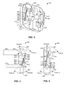
FIG. 4 is a rear perspective view of the collapsible power adapter shown inFIG. 1 having a quadrilateral linkage and a tension spring actuation mechanism in a deployed position with a portion of the housing removed; -
FIG. 5 is a left side plan view of the collapsible power adapter shown inFIG. 4 in a deployed position; -
FIG. 6 is a left side plan view of the collapsible power adapter shown inFIG .4 in a retracted position; -
FIG. 7 is a left side plan view of a collapsible power adapter having a quadrilateral linkage in a deployed position according to an embodiment of the invention; -
FIG. 8 is a left side plan view of the collapsible power adapter shown inFIG. 7 in a retracted position; -
FIG. 9 is a left side plan view of a collapsible power adapter having a pin and slot linkage in a deployed position according to an embodiment of the invention; -
FIG. 10 is a left side plan view of the collapsible power adapter shown inFIG. 9 in a retracted position; -
FIG. 11 is a left side plan view of a collapsible power adapter having a flexible belt linkage in a deployed position according to an embodiment of the invention; -
FIG. 12 is a left side plan view of the collapsible power adapter shown inFIG. 11 in a retracted position; -
FIG. 13 is a left side plan view of a collapsible power adapter having a pin and slot linkage and a tension spring actuation mechanism in a deployed position according to an embodiment of the invention; -
FIG. 14 is a left side plan view of the collapsible power adapter shown inFIG. 13 in a retracted position; -
FIG. 15 is a left side plan view of a collapsible power adapter having a quadrilateral linkage and a cantilever spring actuation mechanism in a deployed position according to an embodiment of the invention; -
FIG. 16 is a left side plan view of the collapsible power adapter shown inFIG. 15 in a retracted position; -
FIG. 17 is a right side perspective view of a collapsible power adapter having a flexible belt linkage and a magnetic actuation mechanism in a deployed position according to an embodiment of the invention; and -
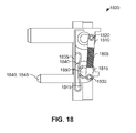
FIG. 18 is a left side plan view of a collapsible power adapter having a modified tension spring and dual electrical contacts according to an embodiment of the invention. - Reference will now be made in detail to representative embodiments illustrated in the accompanying drawings. It should be understood that the following descriptions are not intended to limit the embodiments to one preferred embodiment. To the contrary, it is intended to cover alternatives, modifications, and equivalents as can be included within the spirit and scope of the described embodiments as defined by the appended claims.
- Certain embodiments of the present invention relate to electrical power adapters. While the present invention can be useful for a wide variety of electrical power adapters, some embodiments of the invention are particularly useful for electrical power adapters with collapsible prongs, as described in more detail below. As described herein, some embodiments employ retractable prongs on power adapters that include power conversion circuitry, however some embodiments may also employ retractable prongs on any power plug such as AC plugs for devices that run natively on AC. Retractable prong arrangements/mechanisms as described and/or claimed may be employed on a power plug that does not contain power conversion circuitry within it.
- Many electronic devices such as smart-phones, media players, and tablet computers have electrical power adapters that facilitate battery charging. As an example, a three
prong power adapter 100 compatible with the BS1363 (Type G) standard in the United Kingdom is illustrated inFIG. 1 .Power adapter 100 has three rectangular prongs forming an isosceles triangle and extending away fromhousing 102. Line andneutral prongs 105 are approximately 4 mm by 8 mm and 17.7 mm long, on centers spaced 22.2 mm apart. Earthprong 110 is approximately 4 mm by 8 mm and 22.7 mm long. In other embodiments power adapters having prongs of different physical shapes and dimensions may be used. - In this embodiment,
prongs FIG. 2 illustratesprongs FIG. 3 illustratesprongs adjacent housing 102. Further, inFIG. 3 ,prongs neutral slots 115 andearth slot 120, respectively. Thus,power adapter 100 has reduced physical size inFIG. 3 whereprongs FIG. 1 where the prongs are in the deployed position. As illustrated inFIG. 2 , in some embodiments,pivot point 198 for line and neutralretractable prongs 105 is proximate afirst end 180 of line andneutral slots 115 whilepivot point 199 forearth prong 110 is proximate an end ofearth slot 120 opposite thefirst end 180 of the line and neutral slots. Thus, in some embodiments, line andneutral prongs 105 may pivot in an opposite direction asground prong 110. More specifically, as illustrated inFIG. 2 , when transitioning from the deployed position to the retracted position, line andneutral prongs 105 may pivot up whileground prong 110 may pivot down. -
FIG. 4 illustrates a rear isometric view ofpower adapter 400 with a portion ofhousing 402 removed, showing the internal construction of an embodiment.FIGS. 5 and 6 show the embodiment ofFIG. 4 in the deployed position and the retracted position, respectively. The following discussion will simultaneously referenceFIGS. 4 through 6 . -
Power adapter 400 includes a firstretractable prong 405 and a pair of second retractable prongs 415 (only one of which is shown inFIGS. 4-6 ). Housing 402 can be similar tohousing 102 shown inFIGS. 1-3 and may include slots (not shown inFIGS. 4-6 ) similar toslots prongs FIGS. 1-3 . Firstretractable prong 405 is coupled to a firstrotatable shaft 410 withinhousing 402 such that the first retractable prong can be pivoted from a retracted position in which the first retractable prong is positioned adjacent to the housing to a deployed position in which the first retractable prong extends away from the housing, and can be inserted into an electrical outlet. Secondretractable prong 415 is coupled to a secondrotatable shaft 420 withinhousing 402 such that the second retractable prong can be pivoted from a retracted position in which the second retractable prong is positioned adjacent to the housing, to a deployed position in which the second retractable prong extends away from the housing and can be inserted into an electrical outlet. In some embodiments, secondretractable prong 415 may comprise two adjacent prongs (i.e., a pair of retractable prongs) where each second retractable prong may have a separate rotatable shaft (i.e., a pair of second rotatable shafts). In some embodiments the pair of second rotatable shafts may be axially aligned as illustrated inFIGS. 4-6 . - A
linkage 425 having afirst portion 430 connected to firstrotatable shaft 410 andsecond portion 435 connected to secondrotatable shaft 420 transfers force such that when firstretractable prong 405 is pivoted from the retracted position to the deployed position, secondretractable prong 415 is simultaneously pivoted in the opposite direction from the retracted position to the deployed position. In some embodiments,linkage 425 may be coupled to first and secondrotatable shafts retractable prongs linkage 425 is a planar quadrilateral configuration formed into a clevis such that it may be attached to two secondretractable prongs 415.Linkage 425 will be described in more detail below. Other types of linkages are within the scope of this disclosure and may be employed in other embodiments. Infurther embodiments linkage 425 may be connected to a pair of second rotatable shafts. - In some embodiments,
power adapter 400 may further comprise anactuation mechanism 440 causing firstrotatable shaft 410 and secondrotatable shaft 420 to have a first detent position aligned with the retracted position and a second detent position aligned with the deployed position. As defined herein, a detent position is a point of relative stability or "equilibrium" in the system where the system resists movement. In one embodiment,actuation mechanism 440 may include one or more tension springs 445 that causepower adapter 400 to be relatively unstable between the first detent position and the second detent position such that first and secondretractable prongs retractable prong 405 from the deployed position towards the retracted position,actuation mechanism 440 may cause first and secondretractable prongs - Similarly, when a user rotates first
retractable prong 405 from the retracted position towards the deployed position,actuation mechanism 440 may cause first and secondretractable prongs actuation mechanism 440 may cause first and secondretractable prongs retractable prongs power adapter 400 from a receptacle connector. Similarly, restraining first and secondretractable prongs retractable prongs - As illustrated in
FIGS. 4 through 6 , tension springs 445 may be connected to firstrotatable shaft 410 byfirst crank 450 and to secondrotatable shaft 420 bysecond crank 455. As illustrated inFIGS. 5 and 6 , first crank 450 and second crank 455 may rotate approximately 90 degrees between the retracted position and the deployed position. To create first and second detent positions, first andsecond cranks first pin 460 and asecond pin 465 is shorter in the retracted and deployed positions than it is in between the retracted and deployed positions. That is,tension spring 445 may be stretched more when in between the retracted and deployed positions such that first and secondretractable prongs - As defined herein, the precise position in-between the retracted and deployed positions where the mechanism is bi-stable (i.e., the mechanism is unstable and on the verge of self-actuating to either the retracted or the deployed positions) shall be called the inflection point of the mechanism. Thus, if the mechanism is on the retracted side of the inflection point it will self-actuate towards the retracted position and if it is on the deployed side of the inflection point it will self-actuate towards the deployed position. More specifically, the inflection point is the precise location where the transition from actuating from the retracted position to the deployed position occurs. The inflection point may be designed to be at any location between the retracted and deployed positions. In one embodiment the inflection point may be centered between the retracted and deployed positions (e.g., at a rotation of first crank 450 of 45 degrees). In other embodiments the inflection point may be closer to the retracted position such that the deployed position is more stable and the mechanism doesn't actuate if a user misses the outlet with the plug and moves first and second
retractable prongs first crank 450. In another embodiment the inflection point is located between 24 degrees and 44 degrees from the retracted position. In a further embodiment the inflection point is located between 34 degrees and 44 degrees from the retracted position. - As discussed above,
linkage 425 may be a planar quadrilateral linkage. Planar quadrilateral linkages have four rotating joints and four linkage members. As illustrated inFIGS. 5 and 6 ,first portion 430 oflinkage 425 may be coupled to firstrotatable shaft 410 withfirst hub pin 470 to firstrotatable shaft hub 475. Similarly,second portion 435 oflinkage 425 may be coupled to secondrotatable shaft 420 with asecond hub pin 480 to secondrotatable shaft hub 485. Thus, the four rotating joints are firstrotatable shaft 410,first hub pin 470, secondrotatable shaft 420 andsecond hub pin 480. -
First hub pin 470 may be axially offset from firstrotatable shaft 410 axis of rotation such thatfirst portion 430 oflinkage 425 does not interfere with the first rotatable shaft when transitioning between the retracted and the deployed positions. Similarly,second hub pin 480 may be axially offset from secondrotatable shaft 420 axis of rotation such thatsecond portion 435 oflinkage 425 does not interfere with the second rotatable shaft when transitioning between the retracted and the deployed positions. Thus, the four linkage members are the housing that is disposed between firstrotatable shaft 410 and secondrotatable shaft 420, the offset between firstrotatable shaft 410 andfirst hub pin 470, the offset between secondrotatable shaft 420 andsecond hub pin 480, andlinkage 425. -
Second portion 435 oflinkage 425 may be formed into a clevis and coupled to a pair of secondretractable prongs 415 such the pair of retractable prongs move together. The clevis is a U-shaped member that has holes at the end to acceptsecond hub pin 480. In the embodiment illustrated inFIGS. 4-6 there may be two second hub pins 480, one for each secondretractable prong 415. In other embodiments, there may only be a singlesecond hub pin 480 that connects to both secondretractable prongs 415. In further embodiments,first portion 430 oflinkage 425 may also be formed into a clevis and coupled to a firstretractable prong 405 with firstrotatable shaft hub 475. In other embodiments,first portion 430 oflinkage 425 may not be a clevis and may have only a single member attached to firstrotatable shaft hub 475. - Some embodiments and configurations of the power adapters disclosed herein may include either a linkage or an actuation mechanism, or both. Further, some embodiments may employ different linkage and/or actuation mechanisms than those illustrated herein. The different linkage and actuation mechanisms may be used interchangeably and in different combinations as discussed in more detail below.
- Reference is now made to
FIGS. 7 and 8 that illustrate an embodiment ofpower adapter 700 in the deployed position, and the retracted position, respectively.Power adapter 700 may be similar topower adapter 400 illustrated inFIGS. 4-6 . More specifically,power adapter 700 may employ a quadrilateral linkage mechanism having four rotating joints and four linkage members. The linkage mechanism may include a pair of parallel bars instead of using a clevis. - First
retractable prong 705 is coupled to a first rotatable shaft (not shown) withinhousing 702 such that the first retractable prong can be pivoted from a retracted position in which the first retractable prong is positioned adjacent to the housing, to a deployed position in which the first retractable prong extends away from the housing, and can be inserted into an electrical outlet. In some embodiments secondretractable prong 715 may comprise two adjacent prongs. Secondretractable prong 715 is coupled to a second rotatable shaft (not shown) withinhousing 702 such that the second retractable prong can be pivoted from a retracted position in which the second retractable prong is positioned adjacent to the housing, to a deployed position in which the second retractable prong extends away from the housing, and can be inserted into an electrical outlet. -
Linkage 725 has afirst portion 730 connected to first rotatable shaft (not shown) andsecond portion 735 connected to second rotatable shaft (not shown). More specifically,first portion 730 oflinkage 725 may be coupled to first rotatable shaft (not shown) with afirst pin 770 to first crank 750. Similarly,second portion 735 oflinkage 725 may be coupled to second rotatable shaft (not shown) with asecond pin 780 to second crank 755.Linkage 725 transfers force such that when firstretractable prong 705 is pivoted from the retracted position to the deployed position, secondretractable prong 715 is simultaneously pivoted from the retracted position to the deployed position. In thisembodiment linkage 725 is a planar quadrilateral linkage with a dual-bar configuration such that it may be attached to a pair of secondretractable prongs 415. More specifically, in some embodiments there may be twolinkages 725 such that two secondretractable prongs 715 may be actuated. However, other types of linkages are within the scope of this disclosure and may be employed in further embodiments. - As illustrated, first crank 750 and second crank 755 may rotate approximately 90 degrees between the retracted position and the deployed position.
First pin 770 may be axially offset from first rotatable shaft (not shown) such thatfirst portion 730 oflinkage 725 does not interfere with the first rotatable shaft when transitioning between the retracted and the deployed positions. - Similarly,
second pin 780 may be axially offset from second rotatable shaft (not shown) axis of rotation such thatsecond portion 735 oflinkage 725 does not interfere with the second rotatable shaft when transitioning between the retracted and the deployed positions.Second portion 735 oflinkage 725 may be similarly connected to a pair of secondretractable prongs 715 such the pair of retractable prongs move together. -
FIGS. 9 and 10 show an embodiment ofpower adapter 900, in the deployed position and the retracted position, respectively. The following discussion will simultaneously referenceFIGS. 9 and 10 .Power adapter 900 has a pin andslot linkage mechanism 925 that may be used in some embodiments. -
Power adapter 900 includes a firstretractable prong 905 and a pair of second retractable prongs 915 (only one of which is shown inFIGS. 9-10 ). Housing 902 can be similar tohousing 102 shown inFIGS. 1-3 and may include slots (not shown inFIGS. 4-6 ) similar toslots prongs FIGS. 1-3 . Firstretractable prong 905 is coupled to a first rotatable shaft (not shown) withinhousing 902 such that the first retractable prong can be pivoted from a retracted position in which the first retractable prong is positioned adjacent to the housing, to a deployed position in which the first retractable prong extends away from the housing, and can be inserted into an electrical outlet. In some embodiments secondretractable prong 915 may comprise two adjacent prongs. Secondretractable prong 915 is coupled to a second rotatable shaft (not shown) withinhousing 902 such that the second retractable prong can be pivoted from a retracted position in which the second retractable prong is positioned adjacent to the housing, to a deployed position in which the second retractable prong extends away from the housing, and can be inserted into an electrical outlet. -
Linkage 925 has afirst portion 930 connected to first rotatable shaft (not shown) andsecond portion 935 connected to second rotatable shaft (not shown) and transfers force such that when firstretractable prong 905 is pivoted from the retracted position to the deployed position, secondretractable prong 915 is simultaneously pivoted from the retracted position to the deployed position. In thisembodiment linkage 925 is a pin and slot type with a dual-bar configuration such that it may be attached to a pair of secondretractable prongs 915. More specifically, there may be twolinkages 925 such that two secondretractable prongs 915 may be actuated. However, other types of linkages are within the scope of this disclosure and may be employed in other embodiments. -
First portion 930 oflinkage 925 may be coupled to first rotatable shaft (not shown) with afirst pin 970 on afirst crank 950.First pin 970 may be disposed infirst slot 990 oflinkage 925. Similarly,second portion 935 oflinkage 925 may be coupled to second rotatable shaft (not shown) with asecond pin 980 on asecond crank 955.Second pin 980 may be disposed insecond slot 995 oflinkage 925. As illustrated, first crank 950 and second crank 955 may rotate approximately 90 degrees between the retracted position and the deployed position. As further illustrated inFIG. 9 ,linkage 925 may be in a first position (shown inFIG. 9 as a "left-most" position) where first andsecond pins retractable prongs FIG. 10 ,linkage 925 may be in a second position (shown inFIG. 10 as a "right-most" position) where first andsecond pins retractable prongs linkage 925 may have one or more guides that maintain the linkage in an approximately vertical alignment and don't allow the beam to rotate in plane, as it's illustrated inFIGS 9 and 10 . More specifically, in someembodiments linkage 925 may be constrained to left and right translation only. -
FIGS. 11 and 12 illustrate an embodiment ofpower adapter 1100, in the deployed position and the retracted position, respectively. The following discussion will simultaneously referenceFIGS. 11 and 12 .Power adapter 1100 has aflexible band linkage 1125 mechanism that may be used in some embodiments. -
Power adapter 1100 includes a firstretractable prong 1105 and a pair of second retractable prongs 1115 (only one of which is shown inFIGS. 11-12 ).Housing 1102 can be similar tohousing 102 shown inFIGS. 1-3 and may include slots (not shown inFIGS. 11-12 ) similar toslots prongs FIGS. 1-3 . Firstretractable prong 1105 is coupled to a firstrotatable shaft 1110 withinhousing 1102 such that the first retractable prong can be pivoted from a retracted position in which the first retractable prong is positioned adjacent to the housing, to a deployed position in which the first retractable prong extends away from the housing, and can be inserted into an electrical outlet. In some embodiments secondretractable prong 1115 may comprise two adjacent prongs. Secondretractable prong 1115 is coupled to a secondrotatable shaft 1120 withinhousing 1102 such that the second retractable prong can be pivoted from a retracted position in which the second retractable prong is positioned adjacent to the housing, to a deployed position in which the second retractable prong extends away from the housing, and can be inserted into an electrical outlet. -
Linkage 1125 has afirst portion 1130 connected to firstrotatable shaft 1110 and asecond portion 1135 connected to secondrotatable shaft 1120 and is configured to transfer force such that when firstretractable prong 1105 is pivoted from the retracted position to the deployed position, secondretractable prong 1115 is simultaneously pivoted in the opposite direction from the retracted position to the deployed position. - In some embodiments,
linkage 1125 may comprise one or moreflexible bands 1126.First portion 1130 oflinkage 1125 may be coupled to firstrotatable shaft 1110 withfirst retention feature 1170. Similarly,second portion 1135 oflinkage 1125 may be coupled to secondrotatable shaft 1120 withsecond retention feature 1180. First and second retention features 1170, 1180, respectively may be slots in first and secondrotatable shafts Flexible bands 1126 may be secured with a wedge, a screw, adhesive or any other means.Flexible bands 1126 may be partially wrapped around first and secondrotatable shafts flexible band 1126 with no retention features. As illustrated, firstrotatable shaft 1110 and secondrotatable shaft 1120 may rotate approximately 90 degrees between the retracted position and the deployed position. As further illustrated inFIG. 11 ,linkage 1125 may be in a first position such that when first retractable prong is moved downwards, firstrotatable shaft 1110 rotates counterclockwise.Flexible band 1126 may be configured to reverse the rotation direction causing secondrotatable shaft 1120 to rotate clockwise and secondretractable prong 1115 to retract. That is,flexible band 1126 may be formed in a figure-eight shape as illustrated, as opposed to an elongated O- shape which would not reverse the rotation direction. -
FIGS. 13 and 14 show an embodiment ofpower adapter 1300, in the deployed position and the retracted position, respectively. The following discussion will simultaneously referenceFIGS. 13 and 14 .Power adapter 1300 has a tensionspring actuation mechanism 1340 that may be used in some embodiments. -
Power adapter 1300 includes a firstretractable prong 1305 and a pair of second retractable prongs 1315 (only one of which is shown inFIGS. 13-14 ).Housing 1302 can be similar tohousing 102 shown inFIGS. 1-3 and may include slots (not shown inFIGS. 13-14 ) similar toslots prongs FIGS. 1-3 .Linkage 1325 may be similar to the pin and slot linkage mechanism employed inFIGS. 9 and 10 . However, in this embodiment anactuation mechanism 1340 may also be employed, causing first rotatable shaft (not shown) and second rotatable shaft (not shown) to have a first detent position aligned with the retracted position and a second detent position aligned with the deployed position. In further embodiments,actuation mechanism 1340 may include first and second tension springs 1345, 1346, respectively, thatcause power adapter 1300 to be relatively unstable between the first detent position and the second detent position such that the first and secondretractable prongs retractable prong 1305 from the deployed position towards the retracted position,actuation mechanism 1340 may cause firstretractable prong 1305 and secondretractable prong 1315 to self-actuate (i.e., "snap") to the retracted position. - Similarly, when a user rotates first
retractable prong 1305 from the retracted position towards the deployed position,actuation mechanism 1340 may cause firstretractable prong 1305 and secondretractable prong 1315 to self-actuate to the deployed position. Further,actuation mechanism 1340 may cause first and secondretractable prongs retractable prongs power adapter 1300 from a receptacle connector. Similarly, restraining first and secondretractable prongs retractable prongs - As illustrated in
FIGS. 13 and 14 ,first tension spring 1345 may be connected between afirst pin 1370 and a firstspring attachment point 1360.First pin 1370 may be mounted onfirst crank 1350 and coupled to first rotatable shaft (not shown). Similarly,second tension spring 1346 may be connected between asecond pin 1380 and a secondspring attachment point 1365.Second pin 1380 may be mounted onsecond crank 1355 and coupled to second rotatable shaft (not shown). As further illustrated, first crank 1350 and second crank 1355 may rotate approximately 90 degrees between the retracted position and the deployed position. To create first and second detent positions, first crank 1350 may be oriented such that the distance betweenfirst pin 1370 and firstspring attachment point 1360 is shorter in the retracted and deployed positions than it is in between the retracted and deployed positions. - Similarly, second crank 1355 may be oriented such that the distance between
second pin 1380 and secondspring attachment point 1365 is shorter in the retracted and deployed positions than it is in between the retracted and deployed positions. That is, first and second tension springs 1345, 1346, respectively, may be stretched more when in between the retracted and deployed positions such that first and secondretractable prongs second cranks linkage 1325 may have one or more guides that maintain the linkage in an approximately vertical alignment and don't allow the beam to rotate in plane, as it's illustrated inFIGS. 13 and 14 . More specifically, in someembodiments linkage 1325 may be constrained to left and right translation only. - As discussed above, the inflection point for the mechanism may be designed to be at any location between the retracted and deployed positions. In one embodiment the inflection point may be centered between the retracted and deployed positions (e.g., at a rotation of
first crank 1350 of 45 degrees). In other embodiments the inflection point may be closer to the retracted position. In one embodiment the inflection point is located between 14 degrees and 44 degrees from the retracted position offirst crank 1350. In another embodiment the inflection point is located between 24 degrees and 44 degrees from the retracted position. In a further embodiment the inflection point is located between 34 degrees and 44 degrees from the retracted position. -
FIGS. 15 and 16 show an embodiment ofpower adapter 1500, in the deployed position and the retracted position, respectively. The following discussion will simultaneously referenceFIGS. 15 and 16 .Power adapter 1500 has a cantileverspring actuation mechanism 1540 that may be used in some embodiments. -
Power adapter 1500 includes a firstretractable prong 1505 and a pair of second retractable prongs 1515 (only one of which is shown inFIGS. 15-16 ).Housing 1502 can be similar tohousing 102 shown inFIGS. 1-3 and may include slots (not shown inFIGS. 15-16 ) similar toslots prongs FIGS. 1-3 .Linkage 1525 may be similar to the planar quadrilateral clevis-type linkage mechanism employed inFIGS. 4 through 6 . However, in this embodiment a cantileverspring actuation mechanism 1540 may be employed, causing first rotatable shaft (not shown) and second rotatable shaft (not shown) to have a first detent position aligned with the retracted position and a second detent position aligned with the deployed position. In further embodiments,actuation mechanism 1540 may include first and second cantilever springs 1545, 1546, respectively, thatcause power adapter 1500 to be relatively unstable between the first detent position and the second detent position such that first and secondretractable prongs retractable prong 1505 from the deployed position towards the retracted position,actuation mechanism 1540 may cause firstretractable prong 1505 and secondretractable prong 1515 to self-actuate (i.e., "snap") to the retracted position. - Similarly, when a user rotates first
retractable prong 1505 from the retracted position towards the deployed position,actuation mechanism 1540 may cause firstretractable prong 1505 and secondretractable prong 1515 to self-actuate to the deployed position. Further,actuation mechanism 1540 may cause first and secondretractable prongs retractable prongs power adapter 1500 from a receptacle connector. Similarly, restraining first and secondretractable prongs retractable prongs - As illustrated in
FIGS. 15 and 16 ,first cantilever spring 1545 may be have anattachment end 1548 and anopposite end 1549 placed againstfirst cam 1550 such that firstretractable prong 1505 is restrained in the deployed position. Further, when transitioning to the retracted position (seeFIG. 16 )first cantilever spring 1545 may be deflected, applying a resistive force againstfirst cam 1550. Thus, when transitioning from the retracted position to the deployed position,first cantilever spring 1545 may self-actuate when it gets near the deployed position, "snapping" first and secondretractable prongs - As further illustrated,
second cantilever spring 1546 may be placed againstsecond cam 1555 such that secondretractable prong 1515 is restrained in the deployed and retracted positions.Second cantilever spring 1546 may have adiscontinuity 1547 that interacts withsecond cam 1555 such that when second cam is in the deployed or retracted position, the second cam is restrained (i.e., in a detent). As further illustrated,first cam 1550 andsecond cam 1555 may rotate approximately 90 degrees between the retracted position and the deployed position. - In further embodiments,
power adapter 1500 may be equipped with one or moreelectrical contacts 1599 that conduct through first or second shafts (not shown).Electrical contact 1599 may be preloaded against second shaft (not shown) such that the electrical contact is always in contact with the second shaft when transitioning between the deployed and retracted positions. Second shaft and secondretractable prong 1505 may be made of electrically conductive materials that allow current to pass throughelectrical contact 1599 to secondretractable prong 1515. In some embodiments there may be a pair of secondretractable prongs 1515 and each may have a separate electrical contact. Similarly, an electrical contact may be used for first shaft (not shown) and firstretractable prong 1505. -
FIG. 17 shows an embodiment ofpower adapter 1700, in the deployed position with a portion ofhousing 1702 removed, showing the internal construction.Power adapter 1700 has amagnetic actuation mechanism 1740 that may be used in some embodiments. - First
retractable prong 1705 is coupled to firstrotatable shaft 1710 withinhousing 1702 such that the first retractable prong can be pivoted from a retracted position to a deployed position.Magnetic actuation mechanism 1740 is positioned withinhousing 1702 and is operatively coupled to rotate firstretractable prong 1705 between the retracted position and the deployed position.Magnetic actuation mechanism 1740 includes afirst driver magnet 1745 and a second driver magnet (not shown inFIG. 17 ). A first drivenmagnet 1746 and a second driven magnet (not shown inFIG. 17 ) are attached to firstrotatable shaft 1710. - An actuator (not shown) such as a depressible button or a slide, for example, may be operatively coupled to
magnetic actuation mechanism 1740 to axially move the magnetic drive mechanism from a first position in whichfirst driver magnet 1745 is adjacent first drivenmagnet 1746 and second driver magnet (not shown inFIG. 17 ) is displaced from second driven magnet (not shown inFIG. 17 ), to a second position in which the second driver magnet (not shown inFIG. 17 ) is adjacent to the second driven magnet (not shown inFIG. 17 ) and the first driver magnet is displaced from the first driven magnet. These configurations and others are illustrated in greater detail in United States Patent Application14/260,090 Magnetic actuation mechanism 1740 may have one ormore slides 1747 that enable the actuation mechanism to move in a rectilinear motion without rotating.Magnetic actuation mechanism 1740 may be magnetically coupled to firstrotatable shaft 1710 such that when the magnetic actuation mechanism moves from the first position to the second position, firstretractable prong 1705 is pivoted to the retracted position and when the magnetic actuation mechanism moves from the second position to the first position the first retractable prong is pivoted to the deployed position.Magnetic actuation mechanism 1740 is further described in United States Patent Application14/260,090 filed on April 23, 2014 -
FIG. 17 also illustrates firstrotatable shaft 1710 operably coupled to secondrotatable shaft 1720 with aflexible belt linkage 1725, similar to that illustrated inFIGS. 11 and 12 . One or moreflexible belts 1726 transfer rotational motion from firstrotatable shaft 1710 to secondrotatable shaft 1720, such that when firstretractable prong 1705 moves between the retracted position and the deployed position, secondretractable prong 1715 similarly moves between the retracted position and the deployed position. As illustrated, firstrotatable shaft 1710 and secondrotatable shaft 1720 may rotate approximately 90 degrees between the retracted position and the deployed position. - Reference is now made to
FIG. 18 that illustrates an embodiment ofpower adapter 1800 in the deployed position.Power adapter 1800 may be similar topower adapter 400 illustrated inFIGS. 4-6 . More specifically,power adapter 1800 may employ a tension spring mechanism to actuate the power adapter. However, in this embodiment,tension spring 1805 may have afirst end cap 1810 and asecond end cap 1815. End caps 1810, 1815 may have apertures formed to receivefirst pin 1820 andsecond pin 1830, respectively. In one embodiment,end caps electrical contact 1835 may be used to form an electrical connection to one or more of secondretractable prongs Electrical contact 1835 may have one ormore spring arms rotatable shaft 1850 forming an electrical connection to one or more of secondretractable prongs electrical contact 1835 may be made from a metal or metal alloy that may be plated with one or more metal layers. - The above description discussed four different linkage mechanisms (i.e., quadrilateral with clevis, quadrilateral with dual bar, pin and slot, flexible belt) and three different actuation mechanisms (i.e., tension springs, cantilever springs, magnetic). While
power adapter 400 that included the quadrilateral with a clevis linkage mechanism was illustrated with the tension spring actuator, in otherembodiments power adapter 400 could include either a cantilever spring actuator or a magnetic actuation as described with respect toFIGS. 15-6 andFIG. 17 , respectively. Similarly,power adapter 700 that included the quadrilateral dual bar linkage mechanism could include either a tension spring actuator, a cantilever spring actuator or a magnetic actuation as described with respect toFIGS. 4-6 ,FIGS. 15-6 andFIG. 17 , respectively. Similarly,power adapter 900 that included the pin and slot linkage mechanism could include either a tension spring actuator, a cantilever spring actuator or a magnetic actuation as described with respect toFIGS. 4-6 ,FIGS. 15-6 andFIG. 17 , respectively. Similarly,power adapter 1100 that included the flexible belt linkage mechanism could include either a tension spring actuator, a cantilever spring actuator or a magnetic actuation as described with respect toFIGS. 4-6 ,FIGS. 15-6 andFIG. 17 , respectively. - In the foregoing specification, embodiments of the invention have been described with reference to numerous specific details that may vary from implementation to implementation. The specification and drawings are, accordingly, to be regarded in an illustrative rather than a restrictive sense. The sole and exclusive indicator of the scope of the invention, and what is intended by the applicants to be the scope of the invention, is the literal and equivalent scope of the set of claims that issue from this application, in the specific form in which such claims issue, including any subsequent correction.
Claims (15)
- A power adapter comprising:an adapter housing;a first retractable prong coupled to a first rotatable shaft within the housing such that the first retractable prong can be pivoted from a retracted position in which the first retractable prong is positioned adjacent to the housing, to a deployed position in which the first retractable prong extends away from the housing, and can be inserted into an electrical outlet;a second retractable prong coupled to a second rotatable shaft within the housing such that the second retractable prong can be pivoted from a retracted position in which the second retractable prong is positioned adjacent to the housing, to a deployed position in which the second retractable prong extends away from the housing, and can be inserted into an electrical outlet; anda linkage connected to the first rotatable shaft and to the second rotatable shaft such that when the first retractable prong is pivoted from the retracted position to the deployed position, the second retractable prong is simultaneously pivoted from the retracted position to the deployed position.
- The power adapter of claim 1 wherein the linkage is a planar quadrilateral configuration.
- The power adapter of claim 1 wherein the linkage is a planar quadrilateral configuration formed into a clevis.
- The power adapter of claim 1 wherein the linkage includes one or more flexible belts.
- The power adapter of claim 1 further comprising an actuation mechanism causing the first rotatable shaft and the second rotatable shaft to have a first detent position aligned with the retracted position and a second detent position aligned with the deployed position.
- The power adapter of claim 5 wherein the actuation mechanism includes a tension spring.
- The power adapter of claim 6 wherein the tension spring is connected to the first rotatable shaft by a first crank and is connected to the second rotatable shaft by a crank.
- The power adapter of claim 7 wherein the first crank and the second crank are oriented such that a distance between a first pin disposed in the first crank and a second pin disposed in the second crank is shorter in the retracted and deployed positions than it is when the power adapter is at an inflection point between the retracted and deployed positions.
- The power adapter of claim 5 wherein the actuation mechanism includes a first cantilever spring.
- The power adapter of claim 5 wherein the actuation mechanism includes a magnetic actuation mechanism.
- A collapsible power adapter comprising:a housinga first retractable prong and a pair of second retractable prongs rotatably affixed to the housing;a linkage coupling the first retractable prong to the pair of second retractable prongs such that when the first retractable prong is rotated towards the housing the pair of second retractable prongs simultaneously rotate towards the housing in an opposite direction of the first retractable prong; andan actuation mechanism coupled to the first retractable prong or the pair of second retractable prongs such that the first retractable prong or the pair of second retractable prongs self-actuate to a retracted position or a deployed position.
- The collapsible power adapter of claim 11 wherein the actuation mechanism includes one or more tension springs.
- The collapsible power adapter of claim 11 wherein the first retractable prong rotates about a first shaft and the pair of second retractable prongs rotate about a second shaft.
- The collapsible power adapter of claim 13 wherein the first shaft has a first crank with a first tension spring attachment point and the second shaft has a second crank with a second tension spring attachment point.
- A power adapter comprising:an adapter housing;a first retractable prong coupled to a first rotatable shaft hub within the housing such that the first retractable prong can be pivoted from a retracted position in which the first retractable prong is positioned adjacent to the housing, to a deployed position in which the first retractable prong extends away from the housing, and can be inserted into an electrical outlet;a second retractable prong coupled to a second rotatable shaft hub within the housing such that the second retractable prong can be pivoted from a retracted position in which the second retractable prong is positioned adjacent to the housing, to a deployed position in which the second retractable prong extends away from the housing, and can be inserted into an electrical outlet; anda linkage connected to the first rotatable shaft hub with a first pin that is axially offset from a first rotatable shaft axis and connected to the second rotatable shaft hub with a second pin that is axially offset from a second rotatable shaft axis such that when the first retractable prong is pivoted from the retracted position to the deployed position, the second retractable prong is simultaneously pivoted from the retracted position to the deployed position.
Applications Claiming Priority (2)
| Application Number | Priority Date | Filing Date | Title |
|---|---|---|---|
| US201462013437P | 2014-06-17 | 2014-06-17 | |
| US14/484,145 US9331441B2 (en) | 2014-06-17 | 2014-09-11 | Power adapter with retractable prongs |
Publications (2)
| Publication Number | Publication Date |
|---|---|
| EP2958199A1 true EP2958199A1 (en) | 2015-12-23 |
| EP2958199B1 EP2958199B1 (en) | 2022-02-16 |
Family
ID=53199904
Family Applications (1)
| Application Number | Title | Priority Date | Filing Date |
|---|---|---|---|
| EP15169436.1A Active EP2958199B1 (en) | 2014-06-17 | 2015-05-27 | Power adaptor with retractable prongs |
Country Status (4)
| Country | Link |
|---|---|
| US (1) | US9331441B2 (en) |
| EP (1) | EP2958199B1 (en) |
| GB (2) | GB2550763B (en) |
| HK (1) | HK1215823A1 (en) |
Cited By (1)
| Publication number | Priority date | Publication date | Assignee | Title |
|---|---|---|---|---|
| EP4210178A4 (en) * | 2020-10-28 | 2024-02-28 | Guangdong Oppo Mobile Telecommunications Corp., Ltd. | POWER ADAPTER AND ELECTRONIC DEVICE ASSEMBLY |
Families Citing this family (23)
| Publication number | Priority date | Publication date | Assignee | Title |
|---|---|---|---|---|
| US9331441B2 (en) * | 2014-06-17 | 2016-05-03 | Apple Inc. | Power adapter with retractable prongs |
| USD763794S1 (en) * | 2014-09-05 | 2016-08-16 | Apple Inc. | Adapter |
| HK1197634A2 (en) * | 2014-10-07 | 2015-01-30 | Cord-It Limited | Plug apparatus with movable pin |
| CN204361352U (en) * | 2014-12-19 | 2015-05-27 | 富泰华工业(深圳)有限公司 | Plug |
| TWI559632B (en) * | 2015-01-05 | 2016-11-21 | 勝德國際研發股份有限公司 | A multi-function charger |
| FR3041171A1 (en) * | 2015-09-16 | 2017-03-17 | Gulplug | ELECTRICAL SOCKET BASE WITH RETRACTABLE ELECTRICAL CONTACTS, INCLUDING A SHUTTERING DEVICE |
| US10031536B2 (en) | 2016-01-04 | 2018-07-24 | Gabriel Patent Technologies, Llc | Drift current coulombic storage apparatus |
| CA2961248C (en) * | 2017-03-17 | 2018-05-01 | Cable Gear Holdings Llc | Electrical plug and adapter with retractable prongs |
| US10786129B1 (en) * | 2017-09-15 | 2020-09-29 | Ali Ebrahimi Afrouzi | Recharge station with extendable prongs for mobile robot |
| US10707613B2 (en) * | 2018-09-28 | 2020-07-07 | Dell Products L.P. | Foldable power plug assembly |
| GB201817491D0 (en) * | 2018-10-26 | 2018-12-12 | Design Narrative Ltd | Power adaptor |
| ES2948212T3 (en) * | 2018-12-21 | 2023-09-06 | Worldconnect Ag | Travel adapter and set comprising a travel adapter |
| TWI723674B (en) * | 2019-12-12 | 2021-04-01 | 洋基科技有限公司 | Universal adapter structure |
| US10992093B1 (en) * | 2020-02-21 | 2021-04-27 | Yang Ji Co., Ltd. | Universal adapter structure |
| IT202000016942A1 (en) * | 2020-07-13 | 2022-01-13 | Eggtronic Eng S P A | AN ELECTRIC PLUG |
| CN114421225A (en) * | 2020-10-28 | 2022-04-29 | Oppo广东移动通信有限公司 | Power adapter and electronic equipment assembly |
| CN112864689B (en) * | 2021-01-05 | 2023-06-23 | 深圳市绿联科技股份有限公司 | Storable power plug, patch board and electric appliance |
| USD1009781S1 (en) * | 2021-04-20 | 2024-01-02 | Dongguan Tongqin Electronics Co., Ltd. | Charger |
| USD1016749S1 (en) * | 2021-05-11 | 2024-03-05 | Shenzhen Nearbyexpress Technology Development Company Limited | Charger |
| CN216312188U (en) * | 2021-07-21 | 2022-04-15 | 广东斯泰克电子科技有限公司 | Foldable plug and charger |
| US12224535B2 (en) * | 2022-06-28 | 2025-02-11 | Yang Ji Co., Ltd. | Modularized socket structure |
| TWM636733U (en) * | 2022-07-14 | 2023-01-21 | 勝德國際研發股份有限公司 | Power input device and power module |
| USD1098039S1 (en) * | 2024-06-04 | 2025-10-14 | Baruere Dimirjian | Compact electrical plug |
Citations (8)
| Publication number | Priority date | Publication date | Assignee | Title |
|---|---|---|---|---|
| US4467263A (en) * | 1983-01-31 | 1984-08-21 | Pittway Corporation | Rechargeable battery-powered flashlight system |
| US5628641A (en) * | 1994-02-24 | 1997-05-13 | Asian Micro Sources, Inc. | Collapsible plug device for battery charger |
| US20050239336A1 (en) * | 2004-04-26 | 2005-10-27 | Crupi Theodore P | Electrical multiple outlet device and electrical device having pivotable electrical prongs |
| GB2417141A (en) * | 2004-08-13 | 2006-02-15 | Ridings Ltd | Power plug or adaptor with retractable or foldable pins |
| GB2461324A (en) * | 2008-06-27 | 2009-12-30 | Cheng Uei Prec Ind Co Ltd | Power supply adapter having pivoting pins |
| US20100291779A1 (en) * | 2009-05-18 | 2010-11-18 | Phihong Usa Corporation | Electrical plug device with folding blades |
| US20110097911A1 (en) * | 2009-10-28 | 2011-04-28 | Powertech Industrial Co., Ltd. | Electrical plug |
| US20110097914A1 (en) * | 2009-10-28 | 2011-04-28 | Powertech Industrial Co., Ltd. | Rotatable and foldable electrical plug connector |
Family Cites Families (17)
| Publication number | Priority date | Publication date | Assignee | Title |
|---|---|---|---|---|
| US3025486A (en) * | 1960-02-10 | 1962-03-13 | Falconer John Henry | Three way electric plug |
| US3519914A (en) * | 1966-09-14 | 1970-07-07 | Sony Corp | Charging apparatus for a radio,television receiver or the like |
| GB8801131D0 (en) * | 1988-01-19 | 1988-02-17 | Byford T | Fold down electrical plug |
| GB9119290D0 (en) * | 1991-09-10 | 1991-10-23 | Drewnicki Richard | Electrical adaptor |
| TW255989B (en) * | 1994-02-24 | 1995-09-01 | Asian Micro Sources Inc | Collapsible prong plug device for battery charger |
| JPH11195447A (en) * | 1997-12-26 | 1999-07-21 | Mitsumi Electric Co Ltd | Plug storage type AC adapter |
| US6241538B1 (en) * | 2000-06-08 | 2001-06-05 | Gme-Tech Co., Ltd. | Power supply plug structure for a notebook computer |
| US6939150B1 (en) * | 2002-08-01 | 2005-09-06 | Comarco Wireless Technologies, Inc. | Foldable electrical plug connector |
| TW555262U (en) * | 2002-09-17 | 2003-09-21 | Phihong Entpr Co Ltd | The plug device |
| US6780034B2 (en) * | 2002-11-19 | 2004-08-24 | Shiroshita Industrial Co., Ltd. | Coalescent type power supply conversion plug adapter |
| US7354286B1 (en) * | 2006-12-13 | 2008-04-08 | Xyz Science Co., Ltd. | Adapter for connectors |
| US7614892B2 (en) * | 2007-07-25 | 2009-11-10 | Tung Yan Lau | Electrical plug/socket adaptor |
| US7604492B1 (en) * | 2008-11-21 | 2009-10-20 | Cheng Uei Precision Industry Co., Ltd. | Power supply adapter |
| US8410752B2 (en) * | 2010-10-26 | 2013-04-02 | Research In Motion Limited | Charger device for a portable electronic device |
| US8480416B2 (en) * | 2011-03-29 | 2013-07-09 | Aviiq Ip Inc | Transformable electrical plug devices |
| US9077093B1 (en) * | 2014-04-23 | 2015-07-07 | Apple Inc. | Magnetic rotation actuator |
| US9331441B2 (en) * | 2014-06-17 | 2016-05-03 | Apple Inc. | Power adapter with retractable prongs |
-
2014
- 2014-09-11 US US14/484,145 patent/US9331441B2/en not_active Expired - Fee Related
-
2015
- 2015-05-05 GB GB1712794.5A patent/GB2550763B/en active Active
- 2015-05-05 GB GB1507691.2A patent/GB2522805B/en active Active
- 2015-05-27 EP EP15169436.1A patent/EP2958199B1/en active Active
-
2016
- 2016-04-01 HK HK16103740.9A patent/HK1215823A1/en unknown
Patent Citations (8)
| Publication number | Priority date | Publication date | Assignee | Title |
|---|---|---|---|---|
| US4467263A (en) * | 1983-01-31 | 1984-08-21 | Pittway Corporation | Rechargeable battery-powered flashlight system |
| US5628641A (en) * | 1994-02-24 | 1997-05-13 | Asian Micro Sources, Inc. | Collapsible plug device for battery charger |
| US20050239336A1 (en) * | 2004-04-26 | 2005-10-27 | Crupi Theodore P | Electrical multiple outlet device and electrical device having pivotable electrical prongs |
| GB2417141A (en) * | 2004-08-13 | 2006-02-15 | Ridings Ltd | Power plug or adaptor with retractable or foldable pins |
| GB2461324A (en) * | 2008-06-27 | 2009-12-30 | Cheng Uei Prec Ind Co Ltd | Power supply adapter having pivoting pins |
| US20100291779A1 (en) * | 2009-05-18 | 2010-11-18 | Phihong Usa Corporation | Electrical plug device with folding blades |
| US20110097911A1 (en) * | 2009-10-28 | 2011-04-28 | Powertech Industrial Co., Ltd. | Electrical plug |
| US20110097914A1 (en) * | 2009-10-28 | 2011-04-28 | Powertech Industrial Co., Ltd. | Rotatable and foldable electrical plug connector |
Cited By (1)
| Publication number | Priority date | Publication date | Assignee | Title |
|---|---|---|---|---|
| EP4210178A4 (en) * | 2020-10-28 | 2024-02-28 | Guangdong Oppo Mobile Telecommunications Corp., Ltd. | POWER ADAPTER AND ELECTRONIC DEVICE ASSEMBLY |
Also Published As
| Publication number | Publication date |
|---|---|
| GB2522805B (en) | 2017-09-20 |
| EP2958199B1 (en) | 2022-02-16 |
| US9331441B2 (en) | 2016-05-03 |
| US20150364882A1 (en) | 2015-12-17 |
| GB2550763B (en) | 2019-01-09 |
| GB201507691D0 (en) | 2015-06-17 |
| HK1215823A1 (en) | 2016-09-15 |
| GB2522805A (en) | 2015-08-05 |
| GB2550763A (en) | 2017-11-29 |
| GB201712794D0 (en) | 2017-09-20 |
Similar Documents
| Publication | Publication Date | Title |
|---|---|---|
| US9331441B2 (en) | Power adapter with retractable prongs | |
| US9077093B1 (en) | Magnetic rotation actuator | |
| US8366461B2 (en) | Electrical plug having rotatable prongs | |
| EP2232628B1 (en) | Usb modem devices with a flip antenna and a retractable usb connector | |
| CN103928949B (en) | power adapter | |
| US8491318B2 (en) | Thin socket | |
| US9836087B2 (en) | Flexible display | |
| CN203690534U (en) | Connecting device and portable payment device | |
| US20160197431A1 (en) | Multi-function charger | |
| US20150364873A1 (en) | Reconfigurable plug strip | |
| US9377807B2 (en) | Magnetic connector | |
| US10177490B2 (en) | Magnetic connecting apparatus | |
| JP2012527731A (en) | Power plug device having a folding plug blade | |
| TWI515979B (en) | Power plug device and linkage mechanisum thereof | |
| US20130171864A1 (en) | Cable with multiple, physically selectable connectors | |
| US8105090B1 (en) | Electrical connector assembly | |
| EP2757641A1 (en) | Power device and plug structure thereof | |
| CN102214884A (en) | Charging device | |
| TWI287379B (en) | Sliding mechanism for mobile apparatus, and portable telephone set | |
| JP2004343053A (en) | Transformer equipped with hinge-coupled housing | |
| NL2011791C2 (en) | Electrical connector, connector components of said connector and a device with such a connector component. | |
| US9572274B2 (en) | Securing mechanism | |
| GB2436899A (en) | Electrical plug with movable pin, and two-pin adapter | |
| TWM368925U (en) | Electrical contact and electronic device using the same | |
| EP3051566A1 (en) | Exchange operating mechanism |
Legal Events
| Date | Code | Title | Description |
|---|---|---|---|
| PUAI | Public reference made under article 153(3) epc to a published international application that has entered the european phase |
Free format text: ORIGINAL CODE: 0009012 |
|
| AK | Designated contracting states |
Kind code of ref document: A1 Designated state(s): AL AT BE BG CH CY CZ DE DK EE ES FI FR GB GR HR HU IE IS IT LI LT LU LV MC MK MT NL NO PL PT RO RS SE SI SK SM TR |
|
| AX | Request for extension of the european patent |
Extension state: BA ME |
|
| 17P | Request for examination filed |
Effective date: 20160623 |
|
| RBV | Designated contracting states (corrected) |
Designated state(s): AL AT BE BG CH CY CZ DE DK EE ES FI FR GB GR HR HU IE IS IT LI LT LU LV MC MK MT NL NO PL PT RO RS SE SI SK SM TR |
|
| REG | Reference to a national code |
Ref country code: HK Ref legal event code: DE Ref document number: 1215823 Country of ref document: HK |
|
| STAA | Information on the status of an ep patent application or granted ep patent |
Free format text: STATUS: EXAMINATION IS IN PROGRESS |
|
| 17Q | First examination report despatched |
Effective date: 20170623 |
|
| RAP1 | Party data changed (applicant data changed or rights of an application transferred) |
Owner name: APPLE INC. |
|
| GRAP | Despatch of communication of intention to grant a patent |
Free format text: ORIGINAL CODE: EPIDOSNIGR1 |
|
| STAA | Information on the status of an ep patent application or granted ep patent |
Free format text: STATUS: GRANT OF PATENT IS INTENDED |
|
| INTG | Intention to grant announced |
Effective date: 20211126 |
|
| GRAS | Grant fee paid |
Free format text: ORIGINAL CODE: EPIDOSNIGR3 |
|
| GRAA | (expected) grant |
Free format text: ORIGINAL CODE: 0009210 |
|
| STAA | Information on the status of an ep patent application or granted ep patent |
Free format text: STATUS: THE PATENT HAS BEEN GRANTED |
|
| AK | Designated contracting states |
Kind code of ref document: B1 Designated state(s): AL AT BE BG CH CY CZ DE DK EE ES FI FR GB GR HR HU IE IS IT LI LT LU LV MC MK MT NL NO PL PT RO RS SE SI SK SM TR |
|
| REG | Reference to a national code |
Ref country code: GB Ref legal event code: FG4D |
|
| REG | Reference to a national code |
Ref country code: CH Ref legal event code: EP |
|
| REG | Reference to a national code |
Ref country code: DE Ref legal event code: R096 Ref document number: 602015076905 Country of ref document: DE |
|
| REG | Reference to a national code |
Ref country code: AT Ref legal event code: REF Ref document number: 1469486 Country of ref document: AT Kind code of ref document: T Effective date: 20220315 |
|
| REG | Reference to a national code |
Ref country code: IE Ref legal event code: FG4D |
|
| REG | Reference to a national code |
Ref country code: LT Ref legal event code: MG9D |
|
| REG | Reference to a national code |
Ref country code: NL Ref legal event code: MP Effective date: 20220216 |
|
| REG | Reference to a national code |
Ref country code: AT Ref legal event code: MK05 Ref document number: 1469486 Country of ref document: AT Kind code of ref document: T Effective date: 20220216 |
|
| PG25 | Lapsed in a contracting state [announced via postgrant information from national office to epo] |
Ref country code: SE Free format text: LAPSE BECAUSE OF FAILURE TO SUBMIT A TRANSLATION OF THE DESCRIPTION OR TO PAY THE FEE WITHIN THE PRESCRIBED TIME-LIMIT Effective date: 20220216 Ref country code: RS Free format text: LAPSE BECAUSE OF FAILURE TO SUBMIT A TRANSLATION OF THE DESCRIPTION OR TO PAY THE FEE WITHIN THE PRESCRIBED TIME-LIMIT Effective date: 20220216 Ref country code: PT Free format text: LAPSE BECAUSE OF FAILURE TO SUBMIT A TRANSLATION OF THE DESCRIPTION OR TO PAY THE FEE WITHIN THE PRESCRIBED TIME-LIMIT Effective date: 20220616 Ref country code: NO Free format text: LAPSE BECAUSE OF FAILURE TO SUBMIT A TRANSLATION OF THE DESCRIPTION OR TO PAY THE FEE WITHIN THE PRESCRIBED TIME-LIMIT Effective date: 20220516 Ref country code: NL Free format text: LAPSE BECAUSE OF FAILURE TO SUBMIT A TRANSLATION OF THE DESCRIPTION OR TO PAY THE FEE WITHIN THE PRESCRIBED TIME-LIMIT Effective date: 20220216 Ref country code: LT Free format text: LAPSE BECAUSE OF FAILURE TO SUBMIT A TRANSLATION OF THE DESCRIPTION OR TO PAY THE FEE WITHIN THE PRESCRIBED TIME-LIMIT Effective date: 20220216 Ref country code: HR Free format text: LAPSE BECAUSE OF FAILURE TO SUBMIT A TRANSLATION OF THE DESCRIPTION OR TO PAY THE FEE WITHIN THE PRESCRIBED TIME-LIMIT Effective date: 20220216 Ref country code: ES Free format text: LAPSE BECAUSE OF FAILURE TO SUBMIT A TRANSLATION OF THE DESCRIPTION OR TO PAY THE FEE WITHIN THE PRESCRIBED TIME-LIMIT Effective date: 20220216 Ref country code: BG Free format text: LAPSE BECAUSE OF FAILURE TO SUBMIT A TRANSLATION OF THE DESCRIPTION OR TO PAY THE FEE WITHIN THE PRESCRIBED TIME-LIMIT Effective date: 20220516 |
|
| PG25 | Lapsed in a contracting state [announced via postgrant information from national office to epo] |
Ref country code: PL Free format text: LAPSE BECAUSE OF FAILURE TO SUBMIT A TRANSLATION OF THE DESCRIPTION OR TO PAY THE FEE WITHIN THE PRESCRIBED TIME-LIMIT Effective date: 20220216 Ref country code: LV Free format text: LAPSE BECAUSE OF FAILURE TO SUBMIT A TRANSLATION OF THE DESCRIPTION OR TO PAY THE FEE WITHIN THE PRESCRIBED TIME-LIMIT Effective date: 20220216 Ref country code: GR Free format text: LAPSE BECAUSE OF FAILURE TO SUBMIT A TRANSLATION OF THE DESCRIPTION OR TO PAY THE FEE WITHIN THE PRESCRIBED TIME-LIMIT Effective date: 20220517 Ref country code: FI Free format text: LAPSE BECAUSE OF FAILURE TO SUBMIT A TRANSLATION OF THE DESCRIPTION OR TO PAY THE FEE WITHIN THE PRESCRIBED TIME-LIMIT Effective date: 20220216 Ref country code: AT Free format text: LAPSE BECAUSE OF FAILURE TO SUBMIT A TRANSLATION OF THE DESCRIPTION OR TO PAY THE FEE WITHIN THE PRESCRIBED TIME-LIMIT Effective date: 20220216 |
|
| PG25 | Lapsed in a contracting state [announced via postgrant information from national office to epo] |
Ref country code: IS Free format text: LAPSE BECAUSE OF FAILURE TO SUBMIT A TRANSLATION OF THE DESCRIPTION OR TO PAY THE FEE WITHIN THE PRESCRIBED TIME-LIMIT Effective date: 20220616 |
|
| PG25 | Lapsed in a contracting state [announced via postgrant information from national office to epo] |
Ref country code: SM Free format text: LAPSE BECAUSE OF FAILURE TO SUBMIT A TRANSLATION OF THE DESCRIPTION OR TO PAY THE FEE WITHIN THE PRESCRIBED TIME-LIMIT Effective date: 20220216 Ref country code: SK Free format text: LAPSE BECAUSE OF FAILURE TO SUBMIT A TRANSLATION OF THE DESCRIPTION OR TO PAY THE FEE WITHIN THE PRESCRIBED TIME-LIMIT Effective date: 20220216 Ref country code: RO Free format text: LAPSE BECAUSE OF FAILURE TO SUBMIT A TRANSLATION OF THE DESCRIPTION OR TO PAY THE FEE WITHIN THE PRESCRIBED TIME-LIMIT Effective date: 20220216 Ref country code: EE Free format text: LAPSE BECAUSE OF FAILURE TO SUBMIT A TRANSLATION OF THE DESCRIPTION OR TO PAY THE FEE WITHIN THE PRESCRIBED TIME-LIMIT Effective date: 20220216 Ref country code: DK Free format text: LAPSE BECAUSE OF FAILURE TO SUBMIT A TRANSLATION OF THE DESCRIPTION OR TO PAY THE FEE WITHIN THE PRESCRIBED TIME-LIMIT Effective date: 20220216 Ref country code: CZ Free format text: LAPSE BECAUSE OF FAILURE TO SUBMIT A TRANSLATION OF THE DESCRIPTION OR TO PAY THE FEE WITHIN THE PRESCRIBED TIME-LIMIT Effective date: 20220216 |
|
| REG | Reference to a national code |
Ref country code: DE Ref legal event code: R097 Ref document number: 602015076905 Country of ref document: DE |
|
| PG25 | Lapsed in a contracting state [announced via postgrant information from national office to epo] |
Ref country code: AL Free format text: LAPSE BECAUSE OF FAILURE TO SUBMIT A TRANSLATION OF THE DESCRIPTION OR TO PAY THE FEE WITHIN THE PRESCRIBED TIME-LIMIT Effective date: 20220216 |
|
| PLBE | No opposition filed within time limit |
Free format text: ORIGINAL CODE: 0009261 |
|
| REG | Reference to a national code |
Ref country code: HK Ref legal event code: WD Ref document number: 1215823 Country of ref document: HK |
|
| STAA | Information on the status of an ep patent application or granted ep patent |
Free format text: STATUS: NO OPPOSITION FILED WITHIN TIME LIMIT |
|
| REG | Reference to a national code |
Ref country code: CH Ref legal event code: PL |
|
| REG | Reference to a national code |
Ref country code: BE Ref legal event code: MM Effective date: 20220531 |
|
| 26N | No opposition filed |
Effective date: 20221117 |
|
| GBPC | Gb: european patent ceased through non-payment of renewal fee |
Effective date: 20220527 |
|
| PG25 | Lapsed in a contracting state [announced via postgrant information from national office to epo] |
Ref country code: MC Free format text: LAPSE BECAUSE OF FAILURE TO SUBMIT A TRANSLATION OF THE DESCRIPTION OR TO PAY THE FEE WITHIN THE PRESCRIBED TIME-LIMIT Effective date: 20220216 Ref country code: LU Free format text: LAPSE BECAUSE OF NON-PAYMENT OF DUE FEES Effective date: 20220527 Ref country code: LI Free format text: LAPSE BECAUSE OF NON-PAYMENT OF DUE FEES Effective date: 20220531 Ref country code: CH Free format text: LAPSE BECAUSE OF NON-PAYMENT OF DUE FEES Effective date: 20220531 |
|
| PG25 | Lapsed in a contracting state [announced via postgrant information from national office to epo] |
Ref country code: SI Free format text: LAPSE BECAUSE OF FAILURE TO SUBMIT A TRANSLATION OF THE DESCRIPTION OR TO PAY THE FEE WITHIN THE PRESCRIBED TIME-LIMIT Effective date: 20220216 |
|
| PG25 | Lapsed in a contracting state [announced via postgrant information from national office to epo] |
Ref country code: IE Free format text: LAPSE BECAUSE OF NON-PAYMENT OF DUE FEES Effective date: 20220527 Ref country code: FR Free format text: LAPSE BECAUSE OF NON-PAYMENT OF DUE FEES Effective date: 20220531 |
|
| PG25 | Lapsed in a contracting state [announced via postgrant information from national office to epo] |
Ref country code: GB Free format text: LAPSE BECAUSE OF NON-PAYMENT OF DUE FEES Effective date: 20220527 Ref country code: BE Free format text: LAPSE BECAUSE OF NON-PAYMENT OF DUE FEES Effective date: 20220531 |
|
| P01 | Opt-out of the competence of the unified patent court (upc) registered |
Effective date: 20230526 |
|
| PG25 | Lapsed in a contracting state [announced via postgrant information from national office to epo] |
Ref country code: IT Free format text: LAPSE BECAUSE OF FAILURE TO SUBMIT A TRANSLATION OF THE DESCRIPTION OR TO PAY THE FEE WITHIN THE PRESCRIBED TIME-LIMIT Effective date: 20220216 |
|
| PG25 | Lapsed in a contracting state [announced via postgrant information from national office to epo] |
Ref country code: HU Free format text: LAPSE BECAUSE OF FAILURE TO SUBMIT A TRANSLATION OF THE DESCRIPTION OR TO PAY THE FEE WITHIN THE PRESCRIBED TIME-LIMIT; INVALID AB INITIO Effective date: 20150527 |
|
| PG25 | Lapsed in a contracting state [announced via postgrant information from national office to epo] |
Ref country code: MK Free format text: LAPSE BECAUSE OF FAILURE TO SUBMIT A TRANSLATION OF THE DESCRIPTION OR TO PAY THE FEE WITHIN THE PRESCRIBED TIME-LIMIT Effective date: 20220216 Ref country code: CY Free format text: LAPSE BECAUSE OF FAILURE TO SUBMIT A TRANSLATION OF THE DESCRIPTION OR TO PAY THE FEE WITHIN THE PRESCRIBED TIME-LIMIT Effective date: 20220216 |
|
| PG25 | Lapsed in a contracting state [announced via postgrant information from national office to epo] |
Ref country code: MT Free format text: LAPSE BECAUSE OF FAILURE TO SUBMIT A TRANSLATION OF THE DESCRIPTION OR TO PAY THE FEE WITHIN THE PRESCRIBED TIME-LIMIT Effective date: 20220216 |
|
| PGFP | Annual fee paid to national office [announced via postgrant information from national office to epo] |
Ref country code: DE Payment date: 20250402 Year of fee payment: 11 |
|
| PG25 | Lapsed in a contracting state [announced via postgrant information from national office to epo] |
Ref country code: TR Free format text: LAPSE BECAUSE OF FAILURE TO SUBMIT A TRANSLATION OF THE DESCRIPTION OR TO PAY THE FEE WITHIN THE PRESCRIBED TIME-LIMIT Effective date: 20220216 |