EP2958128A1 - Rotating envelope x-ray tube device - Google Patents
Rotating envelope x-ray tube device Download PDFInfo
- Publication number
- EP2958128A1 EP2958128A1 EP13875076.5A EP13875076A EP2958128A1 EP 2958128 A1 EP2958128 A1 EP 2958128A1 EP 13875076 A EP13875076 A EP 13875076A EP 2958128 A1 EP2958128 A1 EP 2958128A1
- Authority
- EP
- European Patent Office
- Prior art keywords
- envelope
- electrons
- target
- shield ring
- cathode
- Prior art date
- Legal status (The legal status is an assumption and is not a legal conclusion. Google has not performed a legal analysis and makes no representation as to the accuracy of the status listed.)
- Withdrawn
Links
- ZOKXTWBITQBERF-UHFFFAOYSA-N Molybdenum Chemical compound [Mo] ZOKXTWBITQBERF-UHFFFAOYSA-N 0.000 claims description 4
- 229910045601 alloy Inorganic materials 0.000 claims description 4
- 239000000956 alloy Substances 0.000 claims description 4
- 239000000470 constituent Substances 0.000 claims description 4
- 229910052750 molybdenum Inorganic materials 0.000 claims description 4
- 239000011733 molybdenum Substances 0.000 claims description 4
- WFKWXMTUELFFGS-UHFFFAOYSA-N tungsten Chemical compound [W] WFKWXMTUELFFGS-UHFFFAOYSA-N 0.000 claims description 4
- 229910052721 tungsten Inorganic materials 0.000 claims description 4
- 239000010937 tungsten Substances 0.000 claims description 4
- 229910052715 tantalum Inorganic materials 0.000 claims description 3
- GUVRBAGPIYLISA-UHFFFAOYSA-N tantalum atom Chemical compound [Ta] GUVRBAGPIYLISA-UHFFFAOYSA-N 0.000 claims description 3
- 238000002844 melting Methods 0.000 description 12
- 230000008018 melting Effects 0.000 description 12
- 230000000903 blocking effect Effects 0.000 description 7
- 229910052751 metal Inorganic materials 0.000 description 4
- 239000002184 metal Substances 0.000 description 4
- 238000012986 modification Methods 0.000 description 4
- 230000004048 modification Effects 0.000 description 4
- 239000010936 titanium Substances 0.000 description 4
- 238000010276 construction Methods 0.000 description 3
- 238000000034 method Methods 0.000 description 3
- 230000005540 biological transmission Effects 0.000 description 2
- 238000003745 diagnosis Methods 0.000 description 2
- 238000010894 electron beam technology Methods 0.000 description 2
- 239000010935 stainless steel Substances 0.000 description 2
- 229910001220 stainless steel Inorganic materials 0.000 description 2
- RTAQQCXQSZGOHL-UHFFFAOYSA-N Titanium Chemical compound [Ti] RTAQQCXQSZGOHL-UHFFFAOYSA-N 0.000 description 1
- 230000001133 acceleration Effects 0.000 description 1
- 239000000919 ceramic Substances 0.000 description 1
- 230000000694 effects Effects 0.000 description 1
- 230000005684 electric field Effects 0.000 description 1
- 239000011810 insulating material Substances 0.000 description 1
- 230000002093 peripheral effect Effects 0.000 description 1
- 230000001502 supplementing effect Effects 0.000 description 1
- 229910052719 titanium Inorganic materials 0.000 description 1
- 238000002834 transmittance Methods 0.000 description 1
Images


Classifications
-
- H—ELECTRICITY
- H01—ELECTRIC ELEMENTS
- H01J—ELECTRIC DISCHARGE TUBES OR DISCHARGE LAMPS
- H01J35/00—X-ray tubes
- H01J35/02—Details
- H01J35/16—Vessels; Containers; Shields associated therewith
-
- H—ELECTRICITY
- H01—ELECTRIC ELEMENTS
- H01J—ELECTRIC DISCHARGE TUBES OR DISCHARGE LAMPS
- H01J35/00—X-ray tubes
- H01J35/24—Tubes wherein the point of impact of the cathode ray on the anode or anticathode is movable relative to the surface thereof
- H01J35/30—Tubes wherein the point of impact of the cathode ray on the anode or anticathode is movable relative to the surface thereof by deflection of the cathode ray
- H01J35/305—Tubes wherein the point of impact of the cathode ray on the anode or anticathode is movable relative to the surface thereof by deflection of the cathode ray by using a rotating X-ray tube in conjunction therewith
-
- H—ELECTRICITY
- H01—ELECTRIC ELEMENTS
- H01J—ELECTRIC DISCHARGE TUBES OR DISCHARGE LAMPS
- H01J2235/00—X-ray tubes
- H01J2235/16—Vessels
- H01J2235/165—Shielding arrangements
- H01J2235/168—Shielding arrangements against charged particles
Definitions
- This invention relates to an envelope rotation type X-ray tube apparatus having an envelope rotatable with a target.
- a conventional X-ray tube apparatus as shown in Fig. 4 , includes a cathode 105 which releases electrons (also called thermion or electron beams), deflection coils 106 which deflect the electrons released from the cathode 105, a target 107 which generates X-rays (with sign xr in Fig. 4 ) by allowing the electrons deflected by the deflection coils 106 to bombard on its disk peripheries (see Patent Document 1, for example).
- An envelope rotation type X-ray tube 101 has an envelope 102 rotatable about a rotation center line R with the target 107.
- the target 107 is an anode.
- a tube voltage is applied between the cathode 105 and the target 107 which is an anode.
- the tube voltage is a voltage for accelerating the electrons released from the cathode 105.
- An amount of deflection of the electrons deflected by the deflection coils 106 depends on the tube voltage. Therefore, in order to keep constant focal positions for causing the electrons to bombard on positions of the target 107 set beforehand and generate X-rays, an amount of current flowing to the deflection coils 106 is controlled according to variations in the tube voltage.
- Patent Document 2 discloses a construction for supplementing recoil electrons, among electrons having bombarded on a rotating anode target, which repeat scattering without being converted into heat or X-rays.
- control is made to apply the tube voltage, for example, after fixing the current flowing to the deflection coils 106.
- the tube voltage when the tube voltage is low, the amount of deflection of the electrons will become large.
- the electrons will strike outer peripheral parts outward of a focal track of the target 107, or will strike the envelope 102.
- a rise time and a fall time of the tube voltage as shown in Fig. 5 , there inevitably exist periods when the tube voltage is low, though short in time. In such periods, the amount of deflection of the electrons becomes large, causing the electrons to strike the envelope 102.
- the tube voltage is usually controlled to have a predetermined value, but this control may fail to attain perfection when a discharge occurs between the cathode 105 and the target 107 which is an anode. There can also be a case where the tube voltage lowers temporarily. Further, malfunctioning of a high voltage power source can lower the tube voltage below a set value. In such cases, the electrons will strike the envelope 102.
- the envelope 102 may be damaged when the electrons strike the envelope 102.
- the envelope 102 is usually made of stainless steel or a Ti (titanium) alloy, which can melt even with a brief irradiation of electron beam.
- an X-ray emitting window 102b of the envelope 102 is set to a small thickness from the necessity for X-ray transmission. Therefore, when the X-ray emitting window 102b is damaged, there is a possibility of vacuum leakage.
- the envelope 102 When the electrons strike the envelope 102, there is also a possibility of the envelope 102 becoming melted, with constituents of the envelope 102 scattering to the target 107.
- Soft X-rays are included in X-rays which are generated by the electrons accelerated when the tube voltage is low and bombarding on the target 107.
- Soft X-rays have low transmittance with respect to the human body and tend to be absorbed by the human body. This amounts to the patient being irradiated with X-rays not contributing to diagnosis, which results in a disadvantage such as of increasing the patient's exposure to the X-rays. It is therefore desired to reduce the soft X-rays.
- This invention has been made having regard to the state of the art noted above, and its object is to provide an envelope rotation type X-ray tube apparatus which prevents damage to an envelope caused by electron bombardment. A further object is to provide an envelope rotation type X-ray tube apparatus which reduces soft X-rays.
- this invention provides the following construction.
- An envelope rotation type X-ray tube apparatus comprises a cathode for releasing electrons; an electron deflector for deflecting the electrons released from the cathode; a target for generating X-rays by being bombarded with the electrons deflected by the electron deflector; a shield ring, while allowing passage through a ring interior of those of the electrons deflected by the electron deflector that head for an area of the target set beforehand, blocks electrons heading outward of the area; and an envelope containing the cathode, the target and the shield ring, and rotatable with the target.
- the cathode releases electrons, and the electrons released from the cathode are deflected by the electron deflector.
- the target generates X-rays by being bombarded with the electrons deflected by the electron deflector.
- the shield ring allows passage through the ring interior of those of the electrons deflected by the electron deflector that head for the area of the target set beforehand, and blocks the electrons heading outward of that area. Consequently, the electrons are inhibited from bombarding on areas of the target outward of the area and the envelope. This can prevent damage to the envelope.
- the shield ring is rotatable with the envelope and the target. Consequently, even if the shield ring frequently undergoes a bombardment with electrons when blocking the electrons, the electron bombardment is dispersed, thereby to inhibit melting of the shield ring.
- the envelope rotation type X-ray tube apparatus comprises a controller for controlling, in a state of giving an electron deflecting force set beforehand by the electron deflector, to perform one of application of a tube voltage set beforehand between the cathode and the target and removal of the tube voltage applied. Consequently, the electrons at a time of low tube voltage are blocked by the shield ring against bombardment on the target, thereby to be able to reduce soft X-rays included in the generated X-rays. Further, it is not necessary for the controller to control the deflecting force given to the electron deflector according to the tube voltage, which can simplify control of the electron deflector.
- the shield ring is formed of one of tungsten, molybdenum, tantalum, and an alloy having one of these as a main constituent. That is, the shield ring is formed of metal with a high melting point. Therefore, when blocking the electrons with the shield ring, melting of the shield ring is inhibited even under frequent bombardment with the electrons.
- the shield ring is disposed in a portion having the smallest diameter of the envelope. This allows the shield ring to be formed small.
- the shield ring is disposed in a position closer to the target than a portion having the smallest diameter of the envelope. Consequently, the blocking portion of the shield ring has an increased circumference, to be able to receive the electrons in an enlarged area.
- the cathode releases electrons, and the electrons released from the cathode are deflected by the electron deflector.
- the target generates X-rays by being bombarded with the electrons deflected by the electron deflector.
- the shield ring allows passage through the ring interior of those of the electrons deflected by the electron deflector that head for the area of the target set beforehand, and blocks the electrons heading outward of that area. Consequently, the electrons are inhibited from bombarding on areas of the target outward of the area and the envelope. This can prevent damage to the envelope.
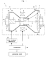
- Fig. 1 is a schematic view of an envelope rotation type X-ray tube apparatus according to the embodiment.
- Fig. 2 is an enlarged view of a portion of Fig. 1 .
- An envelope rotation type X-ray tube apparatus 1 includes an envelope 2 shaped to have a constricted middle portion.
- the envelope 2 has rotary shafts 3a and 3b arranged at opposite ends thereof.
- the rotary shafts 3a and 3b are rotatably supported by bearings 4.
- the envelope 2 has an envelope body 2a, an X-ray emitting window 2b and an insulating wall 2c.
- the envelope body 2a is formed of stainless steel, Ti or the like while the X-ray emitting window 2b is formed of Ti or the like.
- the insulating wall 2c is formed of an insulating material such as ceramics.
- the X-ray emitting window 2b is set to a small thickness from the necessity for X-ray transmission as noted hereinbefore.
- the envelope rotation type X-ray tube apparatus 1 includes a cathode 5 which releases electrons, deflection coils 6 which deflect the electrons released from the cathode 5, and a target 7 which generates X-rays by being bombarded with the electrons deflected by the deflection coils 6.
- the cathode 5 and target 7 are arranged opposite each other on a rotation center line R.
- the cathode 5 releases the electrons toward the target 7 along the rotation center line R.
- the cathode 5 has a disk-shaped electron emission source (emitter) and a converging electrode (neither shown).
- the deflection coils 6 are arranged outside and adjacent the constriction of the envelope 2. Although two deflection coils 6 are arranged opposite each other across the rotation center line R in Fig. 1 , four deflection coils 6 are provided like a quadrupole coil, for example. The four deflection coils 6 can deflect the electrons upward, downward and in the depth directions of the plane of the drawing. The deflection coils 6 correspond to the electron deflector in this invention.
- the target 7 is formed of metal with a high melting point such as tungsten or molybdenum.
- the target 7 serves as an outer wall of the envelope 2 as shown in Fig. 1 , and the rotary shaft 3b is provided on the target 7.
- the envelope 2 instead of the target 7 serving as the outer wall, the envelope 2 may be provided to cover an outer wall adjacent the target 7, with the target 7 attached to this outer wall. The same applies also to the cathode 5.
- an electron accelerating and converging element 8 is provided for accelerating and converging the electrons released from the cathode 5.
- the electron accelerating and converging element 8 is an anode, and not only the electron accelerating and converging element 8, but the envelope body 2a, X-ray emitting window 2b and target 7 are also anodes. That is, the electron accelerating and converging element 8 is at the same potential as the envelope body 2a, X-ray emitting window 2b and target 7.
- the shield ring 11 is a ring-shaped (cylindrical) member, and is attached to the envelope body 2a.
- the shield ring 11 is formed of tungsten, molybdenum or tantalum, or an alloy having one of these as a main constituent. That is, the shield ring 11 is formed of metal with a high melting point. Therefore, when blocking the electrons with the shield ring 11, melting of the shield ring 11 is inhibited even under frequent bombardment with the electrons.
- the shield ring 11 while allowing passage through the ring interior of those of the electrons deflected by the deflection coils 6 that head for an area F (see Fig. 2 ) of the target 7 defining a focal track set beforehand, blocks the electrons heading outward of that area F. That is, the electrons deflected by the deflection coils 6 pass through the ring interior of the shield ring 11, and reach the area F of the target 7 defining the focal track set beforehand. When the amount of deflection of the electrons by the deflection coils 6 is enlarged, the electrons will strike the inner wall of the shield ring 11 to be captured.
- the electrons are therefore prevented from flying to outer peripheries outward of the area F of the target 7 defining the focal track set beforehand, and to the envelope 2 and X-ray emitting window 2a.
- the focal track is a track of focal positions where the electrons bombard to generate X-rays, and is formed to describe a circle on the target 7.
- the side of the shield ring 11 opposed to the target 7 is set such that an outer side of the area F of the target 7 defining the focal track be a boundary.
- the side of the shield ring 11 opposed to the cathode 5 is set to cover a range where bombardments on the envelope 2 are assumed to occur as a result of large deflections by the deflection coils 6.
- the envelope rotation type X-ray tube apparatus 1 has the entire envelope 2 rotated in use. That is, the envelope 2, rotary shafts 3a and 3b, cathode 5, target 7, electron accelerating and converging element 8 and shield ring 11 are integrated, and these integrated envelope 2 and so on are rotated about the rotation center line R by a driver such as a motor not shown.
- the shield ring 11 is therefore constructed to rotate with the envelope 2 and target 7. Consequently, even if the shield ring 11 frequently undergoes a bombardment with electrons when blocking the electrons, the electron bombardment is dispersed, thereby to inhibit melting of the shield ring 11.
- a space surrounded by the envelope 2 and target 7 is in a vacuum state.
- the envelope 2 and so on are contained in a housing 13, and a space between the envelope 2 and so on and the housing 13 is filled with insulating oil.
- the envelope rotation type X-ray tube apparatus 1 includes a controller 15 for performing overall control of the respective components of this apparatus 1, an operating unit 17 for operating the envelope rotation type X-ray tube apparatus 1, and a high voltage generator (high voltage power source) 19 for supplying a tube voltage and a tube current required for X-ray generation.
- the operating unit 17 is made up of switches, a touch panel input unit and so on.
- the controller 15 is formed of a central processing unit (CPU) and so on.
- the controller 15 controls rotation of the envelope 2, controls a power source not shown to supply a current set beforehand to the deflection coils 6, and controls the high voltage generator 19 to supply the tube current and tube voltage between the cathode 5 and the anodes such as the electron accelerating and converging element 8 and so on.
- the controller 15 applies the tube voltage set beforehand between the cathode 5 and the target 7, electron accelerating and converging element 8 and so on. Further, in the state of giving the electron deflecting force set beforehand by the deflection coils 6, the controller 15 removes the applied tube voltage.
- the cathode 5 releases electrons, and the electron accelerating and converging element 8 accelerates and converges the electrons released from the cathode 5.
- the deflection coils 6 deflect the accelerated and converged electrons.
- the deflected electrons pass through the ring interior of the shield ring 11, and bombard on focal positions set beforehand on disk peripheries of the target 7.
- X-rays generate from the focal positions of the target 7 where the electrons have bombarded, and are emitted outward of the envelope rotation type X-ray tube apparatus 1 through the X-ray emitting window 2b.
- the shield ring 11 allows passage through the ring interior of those of the electrons deflected by the deflection coils 6 that head for the area F of the target 7 defining the focal track set beforehand, and blocks the electrons heading outward of that area F. Consequently, the electrons are prevented from striking areas of the target 7 outward of the area F and the envelope 2 such as the X-ray emitting window 2b. Since the shield ring 11 is formed of metal with a high melting point, melting of the shield ring 11 is inhibited even under frequent bombardment with the electrons. Further, since the shield ring 11 rotates with the envelope 2 and target 7, the electron bombardment can be dispersed even if the electrons bombard frequently, thereby to inhibit melting of the shield ring 11.
- the controller 15 In the state of applying the amount of current set beforehand to the deflection coils 6, as shown in Fig. 5 , to give an electron deflecting force set beforehand to the deflection coils 6, the controller 15 generates X-rays by applying the tube voltage set beforehand between the cathode 5 and the target 7, electron accelerating and converging element 8 and so on. Further, in the state of giving the electron deflecting force set beforehand to the deflection coils 6, the controller 15 removes the applied tube voltage to stop the generation of X-rays.
- the controller 15 in the state of applying the amount of current set beforehand to the deflection coils 6 as in this embodiment, selectively performs either application of the tube voltage set beforehand or removal of the applied tube voltage. At this time, those of the electrons deflected by the deflection coils 6 that head for the area of the target 7 set beforehand are allowed to pass through the ring interior of the shield ring 11, and the electrons heading outward of that area are blocked by the shield ring 11. Consequently, the envelope 2 and so on are shielded against the electrons heading therefor, and the electrons at a time of low tube voltage are blocked by the shield ring 11 against bombardment on the target 7, thereby to be able to reduce soft X-rays included in the generated X-rays. Further, it is not necessary for the controller 15 to control the amount of current flowing to the deflection coils 6 according to the tube voltage, which can simplify control of the deflection coils 6.
- the cathode 5 releases electrons, and the electrons released from the cathode 5 are deflected by the deflection coils 6.
- the target 7 generates X-rays by being bombarded with the electrons deflected by the deflection coils 6.
- the shield ring 11 allows passage through the ring interior of those of the electrons deflected by the deflection coils 6 that head for the area F of the target 7 set beforehand, and blocks the electrons heading outward of that area F. Consequently, the electrons are inhibited from bombarding on areas of the target 7 outward of the area F and the envelope 2. This can prevent damage to the envelope 2.
Landscapes
- X-Ray Techniques (AREA)
Abstract
Description
- This invention relates to an envelope rotation type X-ray tube apparatus having an envelope rotatable with a target.
- A conventional X-ray tube apparatus, as shown in
Fig. 4 , includes acathode 105 which releases electrons (also called thermion or electron beams),deflection coils 106 which deflect the electrons released from thecathode 105, atarget 107 which generates X-rays (with sign xr inFig. 4 ) by allowing the electrons deflected by thedeflection coils 106 to bombard on its disk peripheries (seePatent Document 1, for example). An envelope rotationtype X-ray tube 101 has anenvelope 102 rotatable about a rotation center line R with thetarget 107. Thetarget 107 is an anode. - A tube voltage is applied between the
cathode 105 and thetarget 107 which is an anode. The tube voltage is a voltage for accelerating the electrons released from thecathode 105. An amount of deflection of the electrons deflected by thedeflection coils 106 depends on the tube voltage. Therefore, in order to keep constant focal positions for causing the electrons to bombard on positions of thetarget 107 set beforehand and generate X-rays, an amount of current flowing to thedeflection coils 106 is controlled according to variations in the tube voltage. -
Patent Document 2 discloses a construction for supplementing recoil electrons, among electrons having bombarded on a rotating anode target, which repeat scattering without being converted into heat or X-rays. -
- [Patent Document 1]
US 2004/0208287 - [Patent Document 2]
Unexamined Patent Publication No.2011-141956 . - In the
conventional apparatus 101 shown inFig. 4 , control is made to apply the tube voltage, for example, after fixing the current flowing to thedeflection coils 106. At this time, when the tube voltage is low, the amount of deflection of the electrons will become large. When the amount of deflection of the electrons is large, the electrons will strike outer peripheral parts outward of a focal track of thetarget 107, or will strike theenvelope 102. At a rise time and a fall time of the tube voltage, as shown inFig. 5 , there inevitably exist periods when the tube voltage is low, though short in time. In such periods, the amount of deflection of the electrons becomes large, causing the electrons to strike theenvelope 102. - The tube voltage is usually controlled to have a predetermined value, but this control may fail to attain perfection when a discharge occurs between the
cathode 105 and thetarget 107 which is an anode. There can also be a case where the tube voltage lowers temporarily. Further, malfunctioning of a high voltage power source can lower the tube voltage below a set value. In such cases, the electrons will strike theenvelope 102. - The
envelope 102 may be damaged when the electrons strike theenvelope 102. Theenvelope 102 is usually made of stainless steel or a Ti (titanium) alloy, which can melt even with a brief irradiation of electron beam. Particularly anX-ray emitting window 102b of theenvelope 102 is set to a small thickness from the necessity for X-ray transmission. Therefore, when theX-ray emitting window 102b is damaged, there is a possibility of vacuum leakage. When the electrons strike theenvelope 102, there is also a possibility of theenvelope 102 becoming melted, with constituents of theenvelope 102 scattering to thetarget 107. - Numerous soft X-rays are included in X-rays which are generated by the electrons accelerated when the tube voltage is low and bombarding on the
target 107. Soft X-rays have low transmittance with respect to the human body and tend to be absorbed by the human body. This amounts to the patient being irradiated with X-rays not contributing to diagnosis, which results in a disadvantage such as of increasing the patient's exposure to the X-rays. It is therefore desired to reduce the soft X-rays. - This invention has been made having regard to the state of the art noted above, and its object is to provide an envelope rotation type X-ray tube apparatus which prevents damage to an envelope caused by electron bombardment. A further object is to provide an envelope rotation type X-ray tube apparatus which reduces soft X-rays.
- To fulfill the above object, this invention provides the following construction.
- An envelope rotation type X-ray tube apparatus according to this invention comprises a cathode for releasing electrons; an electron deflector for deflecting the electrons released from the cathode; a target for generating X-rays by being bombarded with the electrons deflected by the electron deflector; a shield ring, while allowing passage through a ring interior of those of the electrons deflected by the electron deflector that head for an area of the target set beforehand, blocks electrons heading outward of the area; and an envelope containing the cathode, the target and the shield ring, and rotatable with the target.
- With the envelope rotation type X-ray tube apparatus according to this invention, the cathode releases electrons, and the electrons released from the cathode are deflected by the electron deflector. The target generates X-rays by being bombarded with the electrons deflected by the electron deflector. Here, the shield ring allows passage through the ring interior of those of the electrons deflected by the electron deflector that head for the area of the target set beforehand, and blocks the electrons heading outward of that area. Consequently, the electrons are inhibited from bombarding on areas of the target outward of the area and the envelope. This can prevent damage to the envelope.
- In the envelope rotation type X-ray tube apparatus according this invention, it is preferred that the shield ring is rotatable with the envelope and the target. Consequently, even if the shield ring frequently undergoes a bombardment with electrons when blocking the electrons, the electron bombardment is dispersed, thereby to inhibit melting of the shield ring.
- It is preferred that the envelope rotation type X-ray tube apparatus according to this invention comprises a controller for controlling, in a state of giving an electron deflecting force set beforehand by the electron deflector, to perform one of application of a tube voltage set beforehand between the cathode and the target and removal of the tube voltage applied. Consequently, the electrons at a time of low tube voltage are blocked by the shield ring against bombardment on the target, thereby to be able to reduce soft X-rays included in the generated X-rays. Further, it is not necessary for the controller to control the deflecting force given to the electron deflector according to the tube voltage, which can simplify control of the electron deflector.
- In the envelope rotation type X-ray tube apparatus according this invention, it is preferred that the shield ring is formed of one of tungsten, molybdenum, tantalum, and an alloy having one of these as a main constituent. That is, the shield ring is formed of metal with a high melting point. Therefore, when blocking the electrons with the shield ring, melting of the shield ring is inhibited even under frequent bombardment with the electrons.
- In the envelope rotation type X-ray tube apparatus according this invention, it is preferred that the shield ring is disposed in a portion having the smallest diameter of the envelope. This allows the shield ring to be formed small.
- In the envelope rotation type X-ray tube apparatus according this invention, it is preferred that the shield ring is disposed in a position closer to the target than a portion having the smallest diameter of the envelope. Consequently, the blocking portion of the shield ring has an increased circumference, to be able to receive the electrons in an enlarged area.
- With the envelope rotation type X-ray tube apparatus according to this invention, the cathode releases electrons, and the electrons released from the cathode are deflected by the electron deflector. The target generates X-rays by being bombarded with the electrons deflected by the electron deflector. Here, the shield ring allows passage through the ring interior of those of the electrons deflected by the electron deflector that head for the area of the target set beforehand, and blocks the electrons heading outward of that area. Consequently, the electrons are inhibited from bombarding on areas of the target outward of the area and the envelope. This can prevent damage to the envelope.
-
-
Figure 1 is a schematic view of an envelope rotation type X-ray tube apparatus according to an embodiment; -
Figure 2 is an enlarged fragmentary view of the envelope rotation type X-ray tube apparatus according to the embodiment, showing a way electrons pass through a ring interior of a shield ring and bombard on an area of a target; -
Figure 3 is a schematic view of an envelope rotation type X-ray tube apparatus according to a modification; -
Figure 4 is a schematic view of a conventional envelope rotation type X-ray tube apparatus; and -
Figure 5 is a view showing a relationship between tube voltage and deflecting current, with a horizontal axis representing time. - An embodiment of this invention will be described hereinafter with reference to the drawings.
Fig. 1 is a schematic view of an envelope rotation type X-ray tube apparatus according to the embodiment.Fig. 2 is an enlarged view of a portion ofFig. 1 . - Reference is made to
Fig. 1 . An envelope rotation typeX-ray tube apparatus 1 includes anenvelope 2 shaped to have a constricted middle portion. Theenvelope 2 hasrotary shafts rotary shafts bearings 4. Theenvelope 2 has anenvelope body 2a, anX-ray emitting window 2b and an insulatingwall 2c. Theenvelope body 2a is formed of stainless steel, Ti or the like while theX-ray emitting window 2b is formed of Ti or the like. The insulatingwall 2c is formed of an insulating material such as ceramics. TheX-ray emitting window 2b is set to a small thickness from the necessity for X-ray transmission as noted hereinbefore. - Further, the envelope rotation type
X-ray tube apparatus 1 includes acathode 5 which releases electrons, deflection coils 6 which deflect the electrons released from thecathode 5, and atarget 7 which generates X-rays by being bombarded with the electrons deflected by the deflection coils 6. Thecathode 5 andtarget 7 are arranged opposite each other on a rotation center line R. Thecathode 5 releases the electrons toward thetarget 7 along the rotation center line R. Thecathode 5 has a disk-shaped electron emission source (emitter) and a converging electrode (neither shown). - The deflection coils 6 are arranged outside and adjacent the constriction of the
envelope 2. Although twodeflection coils 6 are arranged opposite each other across the rotation center line R inFig. 1 , fourdeflection coils 6 are provided like a quadrupole coil, for example. The fourdeflection coils 6 can deflect the electrons upward, downward and in the depth directions of the plane of the drawing. The deflection coils 6 correspond to the electron deflector in this invention. - The
target 7 is formed of metal with a high melting point such as tungsten or molybdenum. Thetarget 7 serves as an outer wall of theenvelope 2 as shown inFig. 1 , and therotary shaft 3b is provided on thetarget 7. In this connection, instead of thetarget 7 serving as the outer wall, theenvelope 2 may be provided to cover an outer wall adjacent thetarget 7, with thetarget 7 attached to this outer wall. The same applies also to thecathode 5. - Between the
cathode 5 anddeflection coils 6, an electron accelerating and converging element (also called an anode) 8 is provided for accelerating and converging the electrons released from thecathode 5. The electron accelerating and convergingelement 8 is an anode, and not only the electron accelerating and convergingelement 8, but theenvelope body 2a,X-ray emitting window 2b andtarget 7 are also anodes. That is, the electron accelerating and convergingelement 8 is at the same potential as theenvelope body 2a,X-ray emitting window 2b andtarget 7. - Next, a
shield ring 11 which is the characterizing portion of this invention will be described. Theshield ring 11 is a ring-shaped (cylindrical) member, and is attached to theenvelope body 2a. Theshield ring 11 is formed of tungsten, molybdenum or tantalum, or an alloy having one of these as a main constituent. That is, theshield ring 11 is formed of metal with a high melting point. Therefore, when blocking the electrons with theshield ring 11, melting of theshield ring 11 is inhibited even under frequent bombardment with the electrons. - The
shield ring 11, while allowing passage through the ring interior of those of the electrons deflected by the deflection coils 6 that head for an area F (seeFig. 2 ) of thetarget 7 defining a focal track set beforehand, blocks the electrons heading outward of that area F. That is, the electrons deflected by the deflection coils 6 pass through the ring interior of theshield ring 11, and reach the area F of thetarget 7 defining the focal track set beforehand. When the amount of deflection of the electrons by the deflection coils 6 is enlarged, the electrons will strike the inner wall of theshield ring 11 to be captured. The electrons are therefore prevented from flying to outer peripheries outward of the area F of thetarget 7 defining the focal track set beforehand, and to theenvelope 2 andX-ray emitting window 2a. The focal track is a track of focal positions where the electrons bombard to generate X-rays, and is formed to describe a circle on thetarget 7. - The side of the
shield ring 11 opposed to thetarget 7 is set such that an outer side of the area F of thetarget 7 defining the focal track be a boundary. On the other hand, the side of theshield ring 11 opposed to thecathode 5 is set to cover a range where bombardments on theenvelope 2 are assumed to occur as a result of large deflections by the deflection coils 6. - Incidentally, the envelope rotation type
X-ray tube apparatus 1 has theentire envelope 2 rotated in use. That is, theenvelope 2,rotary shafts cathode 5,target 7, electron accelerating and convergingelement 8 andshield ring 11 are integrated, and theseintegrated envelope 2 and so on are rotated about the rotation center line R by a driver such as a motor not shown. Theshield ring 11 is therefore constructed to rotate with theenvelope 2 andtarget 7. Consequently, even if theshield ring 11 frequently undergoes a bombardment with electrons when blocking the electrons, the electron bombardment is dispersed, thereby to inhibit melting of theshield ring 11. - A space surrounded by the
envelope 2 andtarget 7 is in a vacuum state. Theenvelope 2 and so on are contained in ahousing 13, and a space between theenvelope 2 and so on and thehousing 13 is filled with insulating oil. - Reference is made back to
Fig. 1 . The envelope rotation typeX-ray tube apparatus 1 includes acontroller 15 for performing overall control of the respective components of thisapparatus 1, an operatingunit 17 for operating the envelope rotation typeX-ray tube apparatus 1, and a high voltage generator (high voltage power source) 19 for supplying a tube voltage and a tube current required for X-ray generation. The operatingunit 17 is made up of switches, a touch panel input unit and so on. - The
controller 15 is formed of a central processing unit (CPU) and so on. Thecontroller 15 controls rotation of theenvelope 2, controls a power source not shown to supply a current set beforehand to the deflection coils 6, and controls thehigh voltage generator 19 to supply the tube current and tube voltage between thecathode 5 and the anodes such as the electron accelerating and convergingelement 8 and so on. In a state of applying an amount of current set beforehand to the deflection coils 6 to give an electron deflecting force set beforehand by the deflection coils 6, thecontroller 15 applies the tube voltage set beforehand between thecathode 5 and thetarget 7, electron accelerating and convergingelement 8 and so on. Further, in the state of giving the electron deflecting force set beforehand by the deflection coils 6, thecontroller 15 removes the applied tube voltage. - Next, operation of the envelope rotation type
X-ray tube apparatus 1 will be described. Thecathode 5 releases electrons, and the electron accelerating and convergingelement 8 accelerates and converges the electrons released from thecathode 5. The deflection coils 6 deflect the accelerated and converged electrons. The deflected electrons pass through the ring interior of theshield ring 11, and bombard on focal positions set beforehand on disk peripheries of thetarget 7. X-rays generate from the focal positions of thetarget 7 where the electrons have bombarded, and are emitted outward of the envelope rotation typeX-ray tube apparatus 1 through theX-ray emitting window 2b. - Here, the
shield ring 11 allows passage through the ring interior of those of the electrons deflected by the deflection coils 6 that head for the area F of thetarget 7 defining the focal track set beforehand, and blocks the electrons heading outward of that area F. Consequently, the electrons are prevented from striking areas of thetarget 7 outward of the area F and theenvelope 2 such as theX-ray emitting window 2b. Since theshield ring 11 is formed of metal with a high melting point, melting of theshield ring 11 is inhibited even under frequent bombardment with the electrons. Further, since theshield ring 11 rotates with theenvelope 2 andtarget 7, the electron bombardment can be dispersed even if the electrons bombard frequently, thereby to inhibit melting of theshield ring 11. - In the state of applying the amount of current set beforehand to the deflection coils 6, as shown in
Fig. 5 , to give an electron deflecting force set beforehand to the deflection coils 6, thecontroller 15 generates X-rays by applying the tube voltage set beforehand between thecathode 5 and thetarget 7, electron accelerating and convergingelement 8 and so on. Further, in the state of giving the electron deflecting force set beforehand to the deflection coils 6, thecontroller 15 removes the applied tube voltage to stop the generation of X-rays. - As noted hereinbefore, at the rise and fall of the tube voltage waveform shown in
Fig. 5 , there occur periods when the tube voltage is low. At such times, the amount of deflection of the electrons by the deflection coils 6 will become large, whereby the electrons will head for theenvelope 2 and so on. The electrons heading for theenvelope 2 and so on are blocked by theshield ring 11. There is the following technique also. That is, there is a technique which, when the amount of deflection of the electrons becomes large, controls the amount of current applied to the deflection coils 6 to cause the deflected electrons to head for the area F defining the focal track. This technique would bring about a different problem that numerous soft X-rays not contributing to diagnosis will be included in the X-rays generated by a bombardment resulting from acceleration by a low tube voltage. - However, the
controller 15, in the state of applying the amount of current set beforehand to the deflection coils 6 as in this embodiment, selectively performs either application of the tube voltage set beforehand or removal of the applied tube voltage. At this time, those of the electrons deflected by the deflection coils 6 that head for the area of thetarget 7 set beforehand are allowed to pass through the ring interior of theshield ring 11, and the electrons heading outward of that area are blocked by theshield ring 11. Consequently, theenvelope 2 and so on are shielded against the electrons heading therefor, and the electrons at a time of low tube voltage are blocked by theshield ring 11 against bombardment on thetarget 7, thereby to be able to reduce soft X-rays included in the generated X-rays. Further, it is not necessary for thecontroller 15 to control the amount of current flowing to the deflection coils 6 according to the tube voltage, which can simplify control of the deflection coils 6. - According to this embodiment, the
cathode 5 releases electrons, and the electrons released from thecathode 5 are deflected by the deflection coils 6. Thetarget 7 generates X-rays by being bombarded with the electrons deflected by the deflection coils 6. Here, theshield ring 11 allows passage through the ring interior of those of the electrons deflected by the deflection coils 6 that head for the area F of thetarget 7 set beforehand, and blocks the electrons heading outward of that area F. Consequently, the electrons are inhibited from bombarding on areas of thetarget 7 outward of the area F and theenvelope 2. This can prevent damage to theenvelope 2. - This invention is not limited to the foregoing embodiment, but may be modified as follows:
- (1) In the foregoing embodiment, as shown in
Fig. 1 , theshield ring 11 is disposed in the thinnest portion of theenvelope 2 having a constricted shape. That is, theshield ring 11 is disposed in a portion adjacent the deflection coils 6 with the smallest diameter of theenvelope 2 around the rotation center line R. However, this is not limitative.
As shown inFig. 3 , for example, ashield ring 31 may be disposed in a portion adjacent thetarget 7 with a larger diameter of theenvelope 2 than the portion adjacent the deflection coils 6 with the smallest diameter of theenvelope 2 around the rotation center line R. Since, as a result, theshield ring 31 will block electrons in a position farther away from the rotation center line R than the case of being located adjacent the deflection coils 6, the blocking portion of theshield ring 31 has a longer circumference than that of theshield ring 11 adjacent the deflection coils 6, to be able to receive the electrons in an enlarged area. Therefore, even if theshield ring 31 frequently undergoes a bombardment with the electrons when blocking the electrons, the electron bombardment is further dispersed. This can inhibit melting of theshield ring 31, and can reduce concern about melting.
On the other hand, theshield ring 11 adjacent the deflection coils 6 shown inFig. 1 can be formed small compared with theshield ring 31 adjacent thetarget 7 shown inFig. 3 . The shield rings 11 and 31 may be disposed in any position between the electron accelerating and convergingelement 8 andtarget 7. Specifically, since the electrons are deflected by the deflection coils 6, any position is appropriate as long as it is in a space from ends (sign P inFig. 1 ) opposed to thecathode 5 of the deflection coils 6 to thetarget 7. - (2) In the foregoing embodiment and modification (1), the
shield ring 11 shown inFig. 1 or theshield ring 31 shown inFig. 3 is formed in one piece, but may be formed of a plurality of pieces. For example, theshield ring 11 shown inFig. 1 and theshield ring 31 shown inFig. 3 may be combined. That is, the shield rings 11 and 31 are disposed in the portion with the smallest diameter of theenvelope 2, and in a portion closer to thetarget 7 than the portion with the smallest diameter of theenvelope 2. - (3) In the foregoing embodiment and each modification, the electron accelerating and converging
element 8 is provided as shown inFig. 1 . As shown inFig. 4 , the electron accelerating and convergingelement 8 may be omitted from the construction. - (4) In the foregoing embodiment and each modification, as the electron deflector for deflecting the electrons released from the
cathode 5, the deflection coils 6 are provided which deflect the electrons by means of a magnetic field. For example, the electron deflector may deflect the electrons by means of an electric field. -
- 1
- envelope rotation type X-ray tube apparatus
- 2
- envelope
- 2a
- envelope body
- 2b
- X-ray emitting window
- 5
- cathode
- 6
- deflection coils
- 7
- target
- 11, 31
- shield rings
- 15
- controller
- F
- area
- R
- rotation center line
Claims (6)
- An envelope rotation type X-ray tube apparatus comprising:a cathode for releasing electrons;an electron deflector for deflecting the electrons released from the cathode;a target for generating X-rays by being bombarded with the electron deflected by the electron deflector;a shield ring, while allowing passage through a ring interior of those of the electrons deflected by the electron deflector that head for an area of the target set beforehand, blocks electrons heading outward of the area; andan envelope containing the cathode, the target and the shield ring, and rotatable with the target.
- The envelope rotation type X-ray tube apparatus according to claim 1, wherein the shield ring is rotatable with the envelope and the target.
- The envelope rotation type X-ray tube apparatus according to claim 1 or 2, comprising a controller for controlling, in a state of giving an electron deflecting force set beforehand by the electron deflector, to perform one of application of a tube voltage set beforehand between the cathode and the target and removal of the tube voltage applied.
- The envelope rotation type X-ray tube apparatus according to one of claims 1 to 3, wherein the shield ring is formed of one of tungsten, molybdenum, tantalum, and an alloy having one of these as a main constituent.
- The envelope rotation type X-ray tube apparatus according to one of claims 1 to 4, wherein the shield ring is disposed in a portion having the smallest diameter of the envelope.
- The envelope rotation type X-ray tube apparatus according to one of claims 1 to 5, wherein the shield ring is disposed in a position closer to the target than a portion having the smallest diameter of the envelope.
Applications Claiming Priority (2)
| Application Number | Priority Date | Filing Date | Title |
|---|---|---|---|
| JP2013029186 | 2013-02-18 | ||
| PCT/JP2013/082488 WO2014125702A1 (en) | 2013-02-18 | 2013-12-03 | Rotating envelope x-ray tube device |
Publications (2)
| Publication Number | Publication Date |
|---|---|
| EP2958128A1 true EP2958128A1 (en) | 2015-12-23 |
| EP2958128A4 EP2958128A4 (en) | 2016-04-20 |
Family
ID=51353721
Family Applications (1)
| Application Number | Title | Priority Date | Filing Date |
|---|---|---|---|
| EP13875076.5A Withdrawn EP2958128A4 (en) | 2013-02-18 | 2013-12-03 | Rotating envelope x-ray tube device |
Country Status (4)
| Country | Link |
|---|---|
| US (1) | US9972473B2 (en) |
| EP (1) | EP2958128A4 (en) |
| JP (1) | JP5915810B2 (en) |
| WO (1) | WO2014125702A1 (en) |
Families Citing this family (5)
| Publication number | Priority date | Publication date | Assignee | Title |
|---|---|---|---|---|
| US11282668B2 (en) * | 2016-03-31 | 2022-03-22 | Nano-X Imaging Ltd. | X-ray tube and a controller thereof |
| JP6667366B2 (en) * | 2016-05-23 | 2020-03-18 | キヤノン株式会社 | X-ray generator tube, X-ray generator, and X-ray imaging system |
| CN109564842B (en) | 2016-08-01 | 2021-11-23 | 皇家飞利浦有限公司 | X-ray unit |
| JP7337312B1 (en) | 2022-03-31 | 2023-09-01 | キヤノンアネルバ株式会社 | X-RAY GENERATOR, X-RAY IMAGING DEVICE, AND X-RAY GENERATOR ADJUSTMENT METHOD |
| US12482626B2 (en) * | 2022-08-19 | 2025-11-25 | John Canazon | X-ray tube with corrugated wall |
Family Cites Families (17)
| Publication number | Priority date | Publication date | Assignee | Title |
|---|---|---|---|---|
| NL33344C (en) * | 1929-10-24 | |||
| DE571710C (en) * | 1930-04-24 | 1933-03-03 | Siemens Reiniger Veifa Ges Fue | Facility for operating Roentgen pipes |
| DE19820243A1 (en) * | 1998-05-06 | 1999-11-11 | Siemens Ag | X=ray tube with variable sized X=ray focal spot and focus switching |
| DE19854480A1 (en) * | 1998-11-25 | 2000-06-08 | Siemens Ag | X-ray tube, especially a miniature X-ray tube, has a surface getter produced by getter material transfer from a cathode to the tube interior surface |
| DE19900467A1 (en) * | 1999-01-08 | 2000-04-20 | Siemens Ag | High power rotary anode X-ray tube |
| DE10301068B4 (en) | 2003-01-14 | 2006-09-21 | Siemens Ag | X-ray device with an X-ray tube |
| DE10313897A1 (en) * | 2003-03-27 | 2004-10-28 | Siemens Ag | X-ray tube with radiation emission window and a shield arranged to block an electron beam from the cathode |
| DE102004056110A1 (en) * | 2004-11-19 | 2006-06-01 | Siemens Ag | Rotary piston X-ray radiator used in X-ray medical device comprises X-ray tube having vacuum housing with first partial region rotating with rotating anode |
| JP2009021182A (en) * | 2007-07-13 | 2009-01-29 | Shimadzu Corp | X-ray tube device |
| JP4978695B2 (en) * | 2007-08-09 | 2012-07-18 | 株式会社島津製作所 | X-ray tube device |
| US7835499B2 (en) * | 2007-12-07 | 2010-11-16 | David U. Yu | Compact, short-pulse X-ray and T-ray fused source |
| JP5267202B2 (en) * | 2009-02-23 | 2013-08-21 | 株式会社島津製作所 | X-ray tube device |
| US8565130B2 (en) | 2009-12-16 | 2013-10-22 | Lg Electronics Inc. | Transmitting system and method of processing digital broadcast signal in transmitting system, receiving system and method of receiving digital broadcast signal in receiving system |
| JP5468911B2 (en) | 2010-01-05 | 2014-04-09 | 株式会社日立メディコ | X-ray tube apparatus and X-ray CT apparatus using the same |
| DE102010022595B4 (en) * | 2010-05-31 | 2012-07-12 | Siemens Aktiengesellschaft | X-ray tube with backscatter electron catcher |
| JP5839859B2 (en) * | 2011-06-30 | 2016-01-06 | 株式会社東芝 | X-ray tube device |
| US9208986B2 (en) * | 2012-11-08 | 2015-12-08 | General Electric Company | Systems and methods for monitoring and controlling an electron beam |
-
2013
- 2013-12-03 EP EP13875076.5A patent/EP2958128A4/en not_active Withdrawn
- 2013-12-03 WO PCT/JP2013/082488 patent/WO2014125702A1/en not_active Ceased
- 2013-12-03 JP JP2015500098A patent/JP5915810B2/en active Active
- 2013-12-03 US US14/768,413 patent/US9972473B2/en not_active Expired - Fee Related
Also Published As
| Publication number | Publication date |
|---|---|
| WO2014125702A1 (en) | 2014-08-21 |
| JP5915810B2 (en) | 2016-05-11 |
| EP2958128A4 (en) | 2016-04-20 |
| US20150380201A1 (en) | 2015-12-31 |
| US9972473B2 (en) | 2018-05-15 |
| JPWO2014125702A1 (en) | 2017-02-02 |
Similar Documents
| Publication | Publication Date | Title |
|---|---|---|
| US9972473B2 (en) | Envelope rotation type X-ray tube apparatus | |
| JP6502514B2 (en) | X-ray tube with dual grid and dual filament cathode for electron beam steering and focusing | |
| CN101494149B (en) | Field emitter based electron source for multiple spot x-ray | |
| US20110142193A1 (en) | X-ray tube for microsecond x-ray intensity switching | |
| US8477908B2 (en) | System and method for beam focusing and control in an indirectly heated cathode | |
| EP2869327A1 (en) | X-ray tube | |
| JP2009538500A (en) | X-ray tube where the electron beam is processed simultaneously with the rotating anode motion | |
| US9484179B2 (en) | X-ray tube with adjustable intensity profile | |
| JP5426089B2 (en) | X-ray tube and X-ray CT apparatus | |
| TWI732319B (en) | X-ray generator, X-ray imaging system, and X-ray focus diameter adjustment method | |
| JP2007095689A (en) | X-ray generator with cold electron source | |
| SE424243B (en) | RONTGENROR FOR RONTGENDIAGNOSTIC EQUIPMENT | |
| US9741523B2 (en) | X-ray tube | |
| US9224572B2 (en) | X-ray tube with adjustable electron beam | |
| WO2021246254A1 (en) | Field emission device, field emission method and positioning and fixing method | |
| US20190189384A1 (en) | Bipolar grid for controlling an electron beam in an x-ray tube | |
| US20220406555A1 (en) | Constant discharge current bleeder | |
| JP2018060621A (en) | X-ray tube | |
| JP5267202B2 (en) | X-ray tube device | |
| JP2001273860A (en) | Micro focus x-ray tube device | |
| EP4503086A1 (en) | X-ray generator, x-ray imager, and method for adjusting x-ray generator | |
| EP3226277A1 (en) | Angled flat emitter for high power cathode with electrostatic emission control | |
| EP3518267A1 (en) | X-ray tube | |
| JP2012084400A (en) | Rotating anode x-ray tube and x-ray tube device | |
| US10468222B2 (en) | Angled flat emitter for high power cathode with electrostatic emission control |
Legal Events
| Date | Code | Title | Description |
|---|---|---|---|
| PUAI | Public reference made under article 153(3) epc to a published international application that has entered the european phase |
Free format text: ORIGINAL CODE: 0009012 |
|
| 17P | Request for examination filed |
Effective date: 20150813 |
|
| AK | Designated contracting states |
Kind code of ref document: A1 Designated state(s): AL AT BE BG CH CY CZ DE DK EE ES FI FR GB GR HR HU IE IS IT LI LT LU LV MC MK MT NL NO PL PT RO RS SE SI SK SM TR |
|
| AX | Request for extension of the european patent |
Extension state: BA ME |
|
| A4 | Supplementary search report drawn up and despatched |
Effective date: 20160318 |
|
| RIC1 | Information provided on ipc code assigned before grant |
Ipc: H01J 35/16 20060101AFI20160314BHEP Ipc: H01J 35/26 20060101ALI20160314BHEP Ipc: H01J 35/14 20060101ALI20160314BHEP |
|
| DAX | Request for extension of the european patent (deleted) | ||
| 17Q | First examination report despatched |
Effective date: 20170213 |
|
| GRAP | Despatch of communication of intention to grant a patent |
Free format text: ORIGINAL CODE: EPIDOSNIGR1 |
|
| INTG | Intention to grant announced |
Effective date: 20180514 |
|
| STAA | Information on the status of an ep patent application or granted ep patent |
Free format text: STATUS: THE APPLICATION IS DEEMED TO BE WITHDRAWN |
|
| 18D | Application deemed to be withdrawn |
Effective date: 20180925 |