EP2958101A1 - Methods and apparatus for displaying HDR image on LDR screen - Google Patents
Methods and apparatus for displaying HDR image on LDR screen Download PDFInfo
- Publication number
- EP2958101A1 EP2958101A1 EP14305961.6A EP14305961A EP2958101A1 EP 2958101 A1 EP2958101 A1 EP 2958101A1 EP 14305961 A EP14305961 A EP 14305961A EP 2958101 A1 EP2958101 A1 EP 2958101A1
- Authority
- EP
- European Patent Office
- Prior art keywords
- image
- bit
- ldr
- pixels
- bits
- Prior art date
- Legal status (The legal status is an assumption and is not a legal conclusion. Google has not performed a legal analysis and makes no representation as to the accuracy of the status listed.)
- Withdrawn
Links
- 238000000034 method Methods 0.000 title claims abstract description 78
- 238000005070 sampling Methods 0.000 claims abstract description 99
- 238000006243 chemical reaction Methods 0.000 claims abstract description 41
- 238000013507 mapping Methods 0.000 claims description 7
- 238000004590 computer program Methods 0.000 claims 2
- 238000010586 diagram Methods 0.000 description 5
- 230000000007 visual effect Effects 0.000 description 5
- 230000002146 bilateral effect Effects 0.000 description 3
- 239000003086 colorant Substances 0.000 description 3
- 238000009792 diffusion process Methods 0.000 description 3
- 230000008569 process Effects 0.000 description 3
- 230000008901 benefit Effects 0.000 description 2
- 239000004973 liquid crystal related substance Substances 0.000 description 2
- 238000009877 rendering Methods 0.000 description 2
- 230000007704 transition Effects 0.000 description 2
- 230000003466 anti-cipated effect Effects 0.000 description 1
- 230000003190 augmentative effect Effects 0.000 description 1
- 238000004364 calculation method Methods 0.000 description 1
- 230000002708 enhancing effect Effects 0.000 description 1
- 238000001914 filtration Methods 0.000 description 1
- 238000005259 measurement Methods 0.000 description 1
- 239000000203 mixture Substances 0.000 description 1
- 238000012986 modification Methods 0.000 description 1
- 230000004048 modification Effects 0.000 description 1
- 238000012805 post-processing Methods 0.000 description 1
- 238000012545 processing Methods 0.000 description 1
- 230000009467 reduction Effects 0.000 description 1
Images


Classifications
-
- G—PHYSICS
- G09—EDUCATION; CRYPTOGRAPHY; DISPLAY; ADVERTISING; SEALS
- G09G—ARRANGEMENTS OR CIRCUITS FOR CONTROL OF INDICATING DEVICES USING STATIC MEANS TO PRESENT VARIABLE INFORMATION
- G09G3/00—Control arrangements or circuits, of interest only in connection with visual indicators other than cathode-ray tubes
- G09G3/20—Control arrangements or circuits, of interest only in connection with visual indicators other than cathode-ray tubes for presentation of an assembly of a number of characters, e.g. a page, by composing the assembly by combination of individual elements arranged in a matrix no fixed position being assigned to or needed to be assigned to the individual characters or partial characters
-
- G06T5/92—
-
- G—PHYSICS
- G09—EDUCATION; CRYPTOGRAPHY; DISPLAY; ADVERTISING; SEALS
- G09G—ARRANGEMENTS OR CIRCUITS FOR CONTROL OF INDICATING DEVICES USING STATIC MEANS TO PRESENT VARIABLE INFORMATION
- G09G3/00—Control arrangements or circuits, of interest only in connection with visual indicators other than cathode-ray tubes
- G09G3/20—Control arrangements or circuits, of interest only in connection with visual indicators other than cathode-ray tubes for presentation of an assembly of a number of characters, e.g. a page, by composing the assembly by combination of individual elements arranged in a matrix no fixed position being assigned to or needed to be assigned to the individual characters or partial characters
- G09G3/2007—Display of intermediate tones
- G09G3/2044—Display of intermediate tones using dithering
- G09G3/2051—Display of intermediate tones using dithering with use of a spatial dither pattern
-
- H—ELECTRICITY
- H04—ELECTRIC COMMUNICATION TECHNIQUE
- H04N—PICTORIAL COMMUNICATION, e.g. TELEVISION
- H04N1/00—Scanning, transmission or reproduction of documents or the like, e.g. facsimile transmission; Details thereof
- H04N1/40—Picture signal circuits
- H04N1/40068—Modification of image resolution, i.e. determining the values of picture elements at new relative positions
-
- H—ELECTRICITY
- H04—ELECTRIC COMMUNICATION TECHNIQUE
- H04N—PICTORIAL COMMUNICATION, e.g. TELEVISION
- H04N1/00—Scanning, transmission or reproduction of documents or the like, e.g. facsimile transmission; Details thereof
- H04N1/40—Picture signal circuits
- H04N1/407—Control or modification of tonal gradation or of extreme levels, e.g. background level
-
- H—ELECTRICITY
- H04—ELECTRIC COMMUNICATION TECHNIQUE
- H04N—PICTORIAL COMMUNICATION, e.g. TELEVISION
- H04N19/00—Methods or arrangements for coding, decoding, compressing or decompressing digital video signals
- H04N19/85—Methods or arrangements for coding, decoding, compressing or decompressing digital video signals using pre-processing or post-processing specially adapted for video compression
-
- G—PHYSICS
- G06—COMPUTING; CALCULATING OR COUNTING
- G06T—IMAGE DATA PROCESSING OR GENERATION, IN GENERAL
- G06T2207/00—Indexing scheme for image analysis or image enhancement
- G06T2207/20—Special algorithmic details
- G06T2207/20172—Image enhancement details
- G06T2207/20208—High dynamic range [HDR] image processing
-
- G—PHYSICS
- G09—EDUCATION; CRYPTOGRAPHY; DISPLAY; ADVERTISING; SEALS
- G09G—ARRANGEMENTS OR CIRCUITS FOR CONTROL OF INDICATING DEVICES USING STATIC MEANS TO PRESENT VARIABLE INFORMATION
- G09G2340/00—Aspects of display data processing
- G09G2340/04—Changes in size, position or resolution of an image
- G09G2340/0407—Resolution change, inclusive of the use of different resolutions for different screen areas
- G09G2340/0414—Vertical resolution change
-
- G—PHYSICS
- G09—EDUCATION; CRYPTOGRAPHY; DISPLAY; ADVERTISING; SEALS
- G09G—ARRANGEMENTS OR CIRCUITS FOR CONTROL OF INDICATING DEVICES USING STATIC MEANS TO PRESENT VARIABLE INFORMATION
- G09G2340/00—Aspects of display data processing
- G09G2340/04—Changes in size, position or resolution of an image
- G09G2340/0407—Resolution change, inclusive of the use of different resolutions for different screen areas
- G09G2340/0421—Horizontal resolution change
-
- G—PHYSICS
- G09—EDUCATION; CRYPTOGRAPHY; DISPLAY; ADVERTISING; SEALS
- G09G—ARRANGEMENTS OR CIRCUITS FOR CONTROL OF INDICATING DEVICES USING STATIC MEANS TO PRESENT VARIABLE INFORMATION
- G09G2340/00—Aspects of display data processing
- G09G2340/04—Changes in size, position or resolution of an image
- G09G2340/0407—Resolution change, inclusive of the use of different resolutions for different screen areas
- G09G2340/0428—Gradation resolution change
-
- G—PHYSICS
- G09—EDUCATION; CRYPTOGRAPHY; DISPLAY; ADVERTISING; SEALS
- G09G—ARRANGEMENTS OR CIRCUITS FOR CONTROL OF INDICATING DEVICES USING STATIC MEANS TO PRESENT VARIABLE INFORMATION
- G09G3/00—Control arrangements or circuits, of interest only in connection with visual indicators other than cathode-ray tubes
- G09G3/20—Control arrangements or circuits, of interest only in connection with visual indicators other than cathode-ray tubes for presentation of an assembly of a number of characters, e.g. a page, by composing the assembly by combination of individual elements arranged in a matrix no fixed position being assigned to or needed to be assigned to the individual characters or partial characters
- G09G3/2007—Display of intermediate tones
- G09G3/2059—Display of intermediate tones using error diffusion
-
- G—PHYSICS
- G09—EDUCATION; CRYPTOGRAPHY; DISPLAY; ADVERTISING; SEALS
- G09G—ARRANGEMENTS OR CIRCUITS FOR CONTROL OF INDICATING DEVICES USING STATIC MEANS TO PRESENT VARIABLE INFORMATION
- G09G5/00—Control arrangements or circuits for visual indicators common to cathode-ray tube indicators and other visual indicators
- G09G5/003—Details of a display terminal, the details relating to the control arrangement of the display terminal and to the interfaces thereto
- G09G5/005—Adapting incoming signals to the display format of the display terminal
Definitions
- the present disclosure relates to the technical field of image processing and display, and in particular to methods and apparatus for displaying a High Dynamic Range (HDR) (or Extended Dynamic Range (EDR), which is exchangeable with respect to HDR) image on a Low Dynamic Range (LDR) screen, especially a large LDR screen having a size larger than that of the HDR image.
- HDR High Dynamic Range
- EDR Extended Dynamic Range
- LDR Low Dynamic Range
- the standard High Efficiency Video Coding has adopted a video profile supporting 10-bitss as input video. This format tends to be adopted by many other standardization groups such as Digital Video Broadcasting-Ultra High Definition Television (DVB-UHDTV) and applications.
- DVD-UHDTV Digital Video Broadcasting-Ultra High Definition Television
- most of the existing displays have anticipated the market trend of large images (e.g., 4K) but not the increase of video bit-depth beyond the traditional 8-bits format.
- the dithering technique is used, as shown in Fig. 1 .
- colors that are not available in the palette are approximated by a diffusion of colored pixels from within the available palette (lower bit-depth available color palette).
- the human eye perceives the diffusion as a mixture of the colors within it. Dithered images, particularly those with relatively few colors, can often be distinguished by a characteristic graininess or speckled appearance.
- the dithering process can be modelled locally (assuming a region R(p A ) around a current pixel p A of the original image) as an error minimization problem with 2 terms basically Expression (2), where the first term measures the distance D (e.g., L2 norm) of the converted sample (n right shifted) plus the dither pattern ( dither(p A ) ) (Expression (1)) to the original p A sample value, and the second term evaluate the visual artefact generated by the dithering process.
- imaOut p A p A + n - 1 ⁇ n + ⁇ n ⁇ dither p A min ⁇ p A ⁇ R p A ⁇ D imaOut p A - p A + ⁇ ⁇ visualCost p A
- Fig. 2 illustrates a comparison diagram of four images, including an original image and three images obtained by applying three different dithering methods on the original image.
- the first image is the original image without applying dithering.
- the second to the fourth image are rendered by applying Thresholding dithering (also average dithering), Ordered dithering, and Floyd-Steinberg dithering.
- Floyd-Steinberg dithering is one of the most efficient existing dithering algorithms.
- Floyd-Steinberg dithering is a one pass image algorithm, where rounding errors of samples are distributed to neighboring pixels not yet visited.
- the Floyd-Steinberg error diffusion pattern (Expression (3)) has been chosen carefully so that it produces a checkerboard pattern in areas with intensity of 1 ⁇ 2, it is fairly easy to calculate when the division by 16 is replaced by shifts and it gives subjectively good results in general. 1 16 x 7 3 5 1
- new video formats representing HDR than former LDR ones such as rec.709 are appearing. They allow to represent wider contrast (generally expressed in nits) than it was possible with previous video formats.
- Nit is a unit of visible-light intensity, commonly used to specify the brightness liquid crystal display computer display. One nit is equivalent to one candela per square meter.
- the (augmented contrast ratio) visual experience is mainly characterized in sharper edges, in particular where the contrast ratio is significant.
- Traditional displays are not capable of rendering such HDR content characterized in several thousands of nits.
- the traditional technique used to display a HDR image or video on a LDR screen is to use globally or locally adapted tone mapping algorithms. In that case, the reduction of the contrast ratio removes the HDR visual effect in general.
- the present invention disclosure is provided to solve at least one problem of the prior art.
- the present disclosure will be described in detail with reference to exemplary embodiments. However, the present disclosure is not limited to the embodiments.
- a method for displaying a HDR image on a LDR screen has a size of Nx M pixels and a bit-depth of n bits, and the LDR screen has a size of P ⁇ Q pixels and a bit-depth of m bits, wherein all of N, M, P, Q, n, and m are positive integers, and P>N, Q ⁇ M, and n>m.
- the method comprises: up-sampling the HDR image to obtain an up-sampled HDR image having a size of P ⁇ Q pixels and a bit-depth of n bits; performing bit conversion on the up-sampled HDR image to obtain a LDR image having a size of P ⁇ Q pixels and a bit-depth of m bits; dithering the LDR image based on the HDR image having a size of N ⁇ M pixels and a bit-depth of n bits; and displaying the dithered LDR image on the LDR screen.
- the up-sampling comprises: analyzing local signal characteristics of S ⁇ T pixels in the HDR image, S and T being positive integers, and S ⁇ N and T ⁇ M; selecting one or more up-sampling parameters according to the local signal characteristics; and up-sampling the LDR image by using the selected one or more up-sampling parameters.
- bit conversion is performed by using a tone mapping algorithm.
- the local signal characteristics include a contrast ratio of the HDR image.
- the up-sampling is performed by an up-sampling filter or a sharpen filter.
- a method for displaying a HDR image on a LDR screen has a size of N xM pixels and a bit-depth of n bits, and the LDR screen has a size of P ⁇ Q pixels and a bit-depth of m bits, wherein all of N, M, P, Q, n, and m are positive integers, and P>N, Q ⁇ M, and n>m.
- the method comprises: performing bit conversion on the HDR image to obtain a LDR image having a size of N ⁇ M pixels and a bit-depth of m bits; up-sampling the LDR image to obtain an up-sampled LDR image having a size of P ⁇ Q pixels and a bit-depth of m bits; dithering the up-sampled LDR image based on the HDR image having a size of N ⁇ M pixels and a bit-depth of n bits; and displaying the dithered up-sampled LDR image on the LDR screen.
- a method for displaying a HDR image on a LDR screen has a size of Nx M pixels and a bit-depth of n bits, and the LDR screen has a size of P ⁇ Q pixels and a bit-depth of m bits, wherein all of N, M, P, Q, n, and m are positive integers, and P>N, Q ⁇ M, and n>m.
- the method comprises: up-sampling the HDR image to obtain an up-sampled HDR image having a size of P ⁇ Q pixels and a bit-depth of n bits; performing bit conversion on the up-sampled HDR image to obtain a LDR image having a size of P ⁇ Q pixels and a bit-depth of m bits; and displaying the LDR image on the LDR screen.
- the up-sampling comprises: analyzing local signal characteristics of S ⁇ T pixels in the HDR image, S and T being positive integers, and S ⁇ N and T ⁇ M; selecting one or more up-sampling parameters according to the local signal characteristics; and up-sampling the HDR image by using the selected one or more up-sampling parameters.
- a method for displaying a HDR image on a LDR screen has a size of Nx M pixels and a bit-depth of n bits, and the LDR screen has a size of P ⁇ Q pixels and a bit-depth of m bits, wherein all of N, M, P, Q, n, and m are positive integers, and P>N, Q ⁇ M, and n>m.
- the method comprises: performing bit conversion on the HDR image to obtain a LDR image having a size of N ⁇ M pixels and a bit-depth of m bits; up-sampling the LDR image to obtain an up-sampled LDR image having a size of P ⁇ Q pixels and a bit-depth of m bits; and displaying the up-sampled LDR image on the LDR screen.
- the up-sampling comprises: analyzing local signal characteristics of S ⁇ T pixels in the HDR image, S and T being positive integers, and S ⁇ N and T ⁇ M; selecting one or more up-sampling parameters according to the local signal characteristics; and up-sampling the LDR image by using the selected one or more up-sampling parameters.
- an apparatus for displaying a HDR image on a LDR screen has a size of N xM pixels and a bit-depth of n bits
- the LDR screen has a size of P ⁇ Q pixels and a bit-depth of m bits, wherein all of N, M, P, Q, n, and m are positive integers, and P>N, Q ⁇ M, and n>m.
- the apparatus comprises: an up-sampling unit configured to up-sample the HDR image to obtain an up-sampled HDR image having a size of P ⁇ Q pixels and a bit-depth of n bits; a bit conversion unit configured to perform bit conversion on the up-sampled HDR image to obtain a LDR image having a size of P ⁇ Q pixels and a bit-depth of m bits; a dithering unit configured to dither the LDR image based on the HDR image having a size of N ⁇ M pixels and a bit-depth of n bits; and a displaying unit configured to display the dithered LDR image on the LDR screen.
- an apparatus for displaying a HDR image on a LDR screen has a size of N xM pixels and a bit-depth of n bits
- the LDR screen has a size of P ⁇ Q pixels and a bit-depth of m bits, wherein all of N, M, P, Q, n, and m are positive integers, and P>N, Q ⁇ M, and n>m.
- the apparatus comprises: a bit conversion unit configured to perform bit conversion on the HDR image to obtain a LDR image having a size of N ⁇ M pixels and a bit-depth of m bits; an up-sampling unit configured to up-sample the LDR image to obtain an up-sampled LDR image having a size of P ⁇ Q pixels and a bit-depth of m bits; a dithering unit configured to dither the up-sampled LDR image based on the HDR image having a size of N ⁇ M pixels and a bit-depth of n bits; and a displaying unit configured to display the dithered up-sampled LDR image on the LDR screen.
- an apparatus for displaying a HDR image on a LDR screen has a size of N ⁇ M pixels and a bit-depth of n bits
- the LDR screen has a size of P ⁇ Q pixels and a bit-depth of m bits, wherein all of N, M, P, Q, n, and m are positive integers, and P>N, Q ⁇ M, and n>m.
- the apparatus comprises: an up-sampling unit configured to up-sample the HDR image to obtain an up-sampled HDR image having a size of P ⁇ Q pixels and a bit-depth of n bits; a bit conversion unit configured to perform bit conversion on the up-sampled HDR image to obtain a LDR image having a size of P ⁇ Q pixels and a bit-depth of m bits; and a displaying unit configured to display the LDR image on the LDR screen.
- an up-sampling unit configured to up-sample the HDR image to obtain an up-sampled HDR image having a size of P ⁇ Q pixels and a bit-depth of n bits
- a bit conversion unit configured to perform bit conversion on the up-sampled HDR image to obtain a LDR image having a size of P ⁇ Q pixels and a bit-depth of m bits
- a displaying unit configured to display the LDR image on the LDR screen.
- the up-sampling unit is configured to: analyze local signal characteristics of S ⁇ T pixels in the HDR image, S and T being positive integers, and S ⁇ N and T ⁇ M; select one or more up-sampling parameters according to the local signal characteristics; and up-sample the HDR image by using the selected one or more up-sampling parameters.
- an apparatus for displaying a HDR image on a LDR screen has a size of N ⁇ M pixels and a bit-depth of n bits
- the LDR screen has a size of P ⁇ Q pixels and a bit-depth of m bits, wherein all of N, M, P, Q, n, and m are positive integers, and P>N, Q ⁇ M, and n>m.
- the apparatus comprises: a bit conversion unit configured to perform bit conversion on the HDR image to obtain a LDR image having a size of N ⁇ M pixels and a bit-depth of m bits; an up-sampling unit configured to up-sample the LDR image to obtain an up-sampled LDR image having a size of P ⁇ Q pixels and a bit-depth of m bits; and a displaying unit configured to display the up-sampled LDR image on the LDR screen.
- the up-sampling unit is configured to: analyze local signal characteristics of S ⁇ T pixels in the HDR image, S and T being positive integers, and S ⁇ N and T ⁇ M; select one or more up-sampling parameters according to the local signal characteristics; and up-sample the LDR image by using the selected one or more up-sampling parameters.
- the present invention disclosure allows to display a high bit-depth image on a low bit-depth screen, thereby enabling displaying HDR images on LDR screens.
- low bit depth and high bit depth are used herein to characterize HDR and LDR, respectively. These terms are used to define two different levels of bit depth definition.
- High bit depth is characterized in that it is at a higher bit depth than the low bit depth and, therefore, is a relative term.
- a low bit depth is presumed to be 8 bits, while a high bit depth is presumed to be 10 bits. Due to the relative nature of these terms low bit depth and high bit depth, it is easily seen that the requirement here is that the low bit depth is less than the high bit depth, otherwise the terms are arbitrary.
- the low bit depth may be 4 bit, 6 bit, or for that matter 12 bit, as the only requirement is that the high bit depth envisioned is greater than that of the low bit depth. Therefore, if it is presumed that a bit depth of 12 bits is defined as the low bit depth, then high bit depth may be considered 14 bits, 16 bits, or any other bit depth greater than 12.
- a bit depth of 12 bits is defined as the low bit depth
- high bit depth may be considered 14 bits, 16 bits, or any other bit depth greater than 12.
- the requirement for a high bit depth would be anything greater than 8 bits (10 bits are presumed here for the discussion, but could easily encompass a bit depth of 12 bits, 14 bits, or any other bit depth greater than 8).
- image refers to a still image or a picture from a video sequence.
- Fig. 3 shows a flowchart of a method 300 for displaying a HDR image on a large LDR screen according to a first embodiment of the present disclosure.
- the HDR image has a size of N ⁇ M pixels and a bit-depth of n bits.
- the LDR screen has a size of P ⁇ Q pixels and a bit-depth of m bits. All of N, M, P, Q, n, and m are positive integers, and P>N, Q>M, and n>m.
- the large screen is a relative term here, and the only requirement is that either of horizontal and vertical pixels of the screen is larger than a corresponding one of a target image to be displayed on the screen.
- the HDR image is up-sampled to obtain an up-sampled HDR image having a size of P ⁇ Q pixels and a bit-depth of n bits.
- the up-sampling may be to transform a resolution of the HDR image to that of the large LDR screen.
- the up-sampling in step S310 may include: analyzing local signal characteristics of S ⁇ T pixels in the HDR image, S and T being positive integers, and S ⁇ N and T ⁇ M; selecting one or more up-sampling parameters according to the local signal characteristics; and up-sampling the HDR image by using the selected one or more up-sampling parameters.
- the local signal characteristics may include a contrast ratio of the HDR image.
- the up-sampling in step S310 may be performed by an up-sampling fitter.
- the up-sampling filter includes a bilateral filter and various existing filters capable of achieving up-sampling.
- Parameters used by the up-sampling filter may be locally adapted according to local signal characteristics of the HDR image, e.g., a contrast ratio of the HDR image.
- the up-sampling in step S310 may be further performed by a sharpen fitter.
- the sharpen filter sharpens an image by enhancing color contrast around edges in the image. Such a filter may exaggerate the light and dark edges of the transition improving sharpness by increasing acutance (how quickly image information transitions at an edge).
- the up-sampled HDR image is bit-converted to a LDR image having a size of P ⁇ Q pixels and a bit-depth of m bits.
- various proper techniques such as globally or locally adapted tone mapping algorithms may be applied in the bit-conversion.
- the LDR image is dithered based on the HDR image having a size of N ⁇ M pixels and a bit-depth of n bits.
- the dithering here considers the original image, i.e., the HDR image having a size of N ⁇ M pixels and a bit-depth of n bits.
- the dithering may employ various existing dithering algorithms such as Thresholding dithering, Ordered dithering, Floyd-Steinberg dithering, etc.
- the dithered LDR image is displayed on the LDR screen.
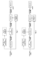
- Fig. 4 schematically illustrates an example procedure of the method 300 according to the first embodiment of the present disclosure.
- the HDR image and the large LDR screen are described as a 10-bitss image having N ⁇ M pixels and a 8-bits screen having 2Nx2M pixels, respectively, it will be appreciated that the present disclosure is not limited to this and various other formats of images and screens are applicable.
- the 10-bitss image having N ⁇ M pixels is firstly up-sampled to a 10-bitss image having 2Nx2M pixels. Then, the 10-bitss image having 2Nx2M pixels is bit-converted to a 8-bits image having 2Nx2M pixels. The 8-bits image having 2Nx2M pixels is then dithered by considering the 10-bitss image having N ⁇ M pixels (i.e., the original image), and thereafter displayed on the LDR screen.
- the original image is considered in the dithering.
- an additional term may be added in the above Expression (2): min ⁇ p A ⁇ R p A ⁇ D ⁇ imaOut p A - p B + ⁇ ⁇ D ⁇ imaOut p A - p A + ⁇ ⁇ visualCost p A
- ⁇ is a down-sampling operator
- (, ) are Lagrangian multipliers.
- the dithering may only consider the original image. For example, ⁇ and/or ⁇ can be set to zero. Setting ⁇ to zero allows to speed-up calculation in the dithering while maintaining the original bit-depth accuracy distribution.
- VisualCost(p A ) may be replaced by VisualCost( ⁇ imaOut(p A )), which means the visual artefacts measurement is performed at the original down-sampled resolution. It should be noted that, depending on the viewing conditions, assessing the visual artefacts at original down-sampled resolution is sufficient (in particular if the viewing distance is above a given threshold, what has been reported in some studies for 4K displays).
- a pattern size of the dithering corresponds to the relative up-sampling ratio between an original image size and a screen rendering size, e.g., 2x2 if performing up-sampling by factor of 2 in both directions (i.e., horizontal pixels and vertical pixels are both up-sampled by a factor of 2).
- the up-sampling may be controlled by locally adapting up-sampling parameters. For example, this may be done by analyzing local signal characteristics of S ⁇ T pixels (S and T are positive integers, and S ⁇ N and T ⁇ M) in the HDR image, selecting one or more up-sampling parameters according to the local signal characteristics, and performing the up-sampling based on the selected on or more up-sampling parameters.
- One major advantage with the method 300 is to allow to display a high bit-depth image on a low bit-depth screen with a large size, thereby enabling displaying HDR images on large LDR screens.
- Fig. 5 shows a flowchart of a method 500 for displaying a HDR image on a large LDR screen according to a second embodiment of the present disclosure.
- the HDR image has a size of N ⁇ M pixels and a bit-depth of n bits.
- the LDR screen has a size of P ⁇ Q pixels and a bit-depth of m bits. All of N, M, P, Q, n, and m are positive integers, and P>N, Q ⁇ M, and n>m.
- bit conversion is performed on the HDR image to obtain a LDR image having a size of N ⁇ M pixels and a bit-depth of m bits.
- the LDR image is up-sampled to obtain an up-sampled LDR image having a size of P ⁇ Q pixels and a bit-depth of m bits.
- the up-sampled LDR image is dithered based on the HDR image having a size of N ⁇ M pixels and a bit-depth of n bits.
- the dithered up-sampled LDR image is displayed on the LDR screen.
- the method 500 mainly differs from the method 300 in that the method 500 firstly performs the bit conversion and then the up-sampling, while it is firstly the up-sampling and then the bit conversion in the method 300. That is, step S510 corresponds to step S320, and the step S520 corresponds to the step S310. Steps 530 and S540 correspond to steps S330 and S340, respectively. In this case, the detailed implementations of steps S510-540 will be similar to those depicted with reference to Fig. 3 , and thus will be omitted here for the sake of brevity.
- Fig. 6 schematically illustrates an example procedure of the method 500 according to the second embodiment of the present disclosure.
- the HDR image and the large LDR screen are described as a 10-bits image having N ⁇ M pixels and a 8-bits screen having 2Nx2M pixels, respectively, it will be appreciated that the present disclosure is not limited to this and various other formats of images and screens are applicable.
- the 10-bits image having N ⁇ M pixels is firstly bit-converted to a 8-bits image having N ⁇ M pixels and then up-sampled to a 8-bits image having 2Nx2M pixels.
- the 8-bits image having 2Nx2M pixels is then dithered by considering the 10-bits image having N ⁇ M pixels (i.e., the original image), and thereafter displayed on the LDR screen.
- Fig. 6 differs from Fig. 4 mainly in swapping bit conversion with up-sampling. So, the detailed implementations described with reference to Fig. 4 may be similarly applied to Fig. 6 .
- Fig. 7 shows a flowchart of a method 700 for displaying a HDR image on a large LDR screen according to a third embodiment of the present disclosure.
- the HDR image has a size of N ⁇ M pixels and a bit-depth of n bits.
- the LDR screen has a size of P ⁇ Q pixels and a bit-depth of m bits. All of N, M, P, Q, n, and m are positive integers, and P>N, Q ⁇ M, and n>m.
- the HDR image is up-sampled to obtain an up-sampled HDR image having a size of P ⁇ Q pixels and a bit-depth of n bits.
- This step is implemented by three sub-steps, i.e., step S711, S 713 and S715.
- step S711 local signal characteristics of S ⁇ T pixels in the HDR image is analyzed.
- S and T are positive integers, and S ⁇ N and T ⁇ M.
- one or more up-sampling parameters are selected according to the local signal characteristics.
- the local signal characteristics may include a contrast ratio of the HDR image.
- the HDR image is up-sampled by using the selected one or more up-sampling parameters.
- bit conversion is performed on the up-sampled HDR image to obtain a LDR image having a size of P ⁇ Q pixels and a bit-depth of m bits. This step is
- the LDR image is displayed on the LDR screen
- Fig. 8 schematically illustrates an example procedure of the method 700 according to the third embodiment of the present disclosure.
- the HDR image and the large LDR screen are described as a 10-bits image having N ⁇ M pixels and a 8-bits screen having 2Nx2M pixels, respectively, it will be appreciated that the present disclosure is not limited to this and various other formats of images and screens are applicable.
- the 10-bits image having N ⁇ M pixels is firstly up-sampled to a 10-bits image having 2Nx2M pixels.
- the up-sampling is controlled by locally adapting up-sampling parameters. To be specific, this is done by analyzing local signal characteristics of S ⁇ T pixels (S and T are positive integers, and S ⁇ N and T ⁇ M) in the HDR image, selecting one or more up-sampling parameters according to the local signal characteristics, and performing the up-sampling based on the selected on or more up-sampling parameters.
- the 10-bits image having 2Nx2M pixels is bit-converted to a 8-bits image having 2Nx2M pixels.
- the 8-bits image having 2Nx2M pixels is finally displayed on the LDR screen.
- the 8-bits image having 2Nx2M pixels may be dithered by considering the original image, i.e., the 10-bits image having N ⁇ M pixels.
- the method 700 differs from the method 300 in that the method 700 compulsorily adapts the up-sampling, while it is only optional in the method 300, and that the method 300 compulsorily applies the dithering, while it is only optional in the method 700.
- the detailed implementations of the method 300 described with reference to Fig 3 and Fig. 4 will be similarly applied to the method 700.
- Fig. 9 shows a flowchart of a method 900 for displaying a HDR image on a large LDR screen according to a fourth embodiment of the present disclosure.
- the HDR image has a size of N ⁇ M pixels and a bit-depth of n bits.
- the LDR screen has a size of P ⁇ Q pixels and a bit-depth of m bits. All of N, M, P, Q, n, and m are positive integers, and P>N, Q ⁇ M, and n>m.
- bit conversion is performed on the HDR image to obtain a LDR image having a size of N ⁇ M pixels and a bit-depth of m bits.
- step S920 the LDR image is up-sampled to obtain an up-sampled LDR image having a size of P ⁇ Q pixels and a bit-depth of m bits.
- This step is implemented by three sub-steps, i.e., step S921, S923 and S925.
- step S921 local signal characteristics of S ⁇ T pixels in the HDR image is analyzed.
- S and T are positive integers, and S ⁇ N and T ⁇ M.
- one or more up-sampling parameters are selected according to the local signal characteristics.
- the local signal characteristics may include a contrast ratio of the HDR image.
- the LDR image is up-sampled by using the selected one or more up-sampling parameters.
- the up-sampled LDR image is displayed on the LDR screen
- the method 900 mainly differs from the method 700 in that the method 900 firstly performs the bit conversion and then the up-sampling, while it is firstly the up-sampling and then the bit conversion in the method 700. That is, step S910 corresponds to step S720, the step S920 corresponds to the step S710, and step 930 corresponds to steps S730. In this case, the detailed implementations of steps S910-930 will be similar to those depicted with reference to Fig. 7 , and thus will be omitted here for the sake of brevity.
- Fig. 10 schematically illustrates an example procedure of the method 900 according to the fourth embodiment of the present disclosure.
- the HDR image and the large LDR screen are described as a 10-bits image having N ⁇ M pixels and a 8-bits screen having 2Nx2M pixels, respectively, it will be appreciated that the present disclosure is not limited to this and various other formats of images and screens are applicable.
- the 10-bits image having N ⁇ M pixels is firstly bit-converted to a 8-bits image having N ⁇ M pixels and then up-sampled to a 8-bits image having 2Nx2M pixels.
- the up-sampling is controlled by locally adapting up-sampling parameters. To be specific, this is done by analyzing local signal characteristics of S ⁇ T pixels (S and T are positive integers, and S ⁇ N and T ⁇ M) in the HDR image, selecting one or more up-sampling parameters according to the local signal characteristics, and performing the up-sampling based on the selected on or more up-sampling parameters.
- the 8-bits image having 2Nx2M pixels is finally displayed on the LDR screen.
- the 8-bits image having 2Nx2M pixels may be dithered by considering the original image, i.e., the 10-bits image having N ⁇ M pixels.
- Fig. 10 differs from Fig. 8 mainly in swapping bit conversion with up-sampling.
- the detailed implementations of the method 700 described with reference to Fig 7 and Fig. 8 will be similarly applied to the method 900.
- the present disclosure allows to display a high bit-depth image on a low bit-depth screen, thereby enabling displaying HDR images on LDR screens.
- Fig. 11 is a schematic block diagram of an apparatus 1100 for displaying a HDR image on a large LDR screen according to some embodiments of the present disclosure.
- the apparatus 1100 is implemented to perform the herein described methods, e.g., the methods 300, 500, 700, or 900.
- the apparatus 1100 may be implemented in a display such as a Liquid Crystal Display (LCD) or Light Emitting Diode (LED) display, a set-top box, or any other appropriate video decoder, or post-processing devices.
- LCD Liquid Crystal Display
- LED Light Emitting Diode
- the arrangement 1100 may include an up-sampling unit 1110, a bit conversion unit 1120, and a displaying unit 1130.
- the apparatus 1100 filter further includes a dithering unit 1140.
- the up-sampling unit 1110 is configured to up-sample the HDR image to obtain an up-sampled HDR image having a size of P ⁇ Q pixels and a bit-depth of n bits.
- the bit conversion unit 1120 is configured to perform bit conversion on the up-sampled HDR image to obtain a LDR image having a size of P ⁇ Q pixels and a bit-depth of m bits.
- the dithering unit 1140 is configured to dither the LDR image based on the HDR image having a size of N ⁇ M pixels and a bit-depth of n bits.
- the displaying unit 1130 is configured to display the dithered LDR image on the LDR screen.
- the apparatus 1100 filter further includes a dithering unit 1140.
- the bit conversion unit 1120 is configured to perform bit conversion on the HDR image to obtain a LDR image having a size of N ⁇ M pixels and a bit-depth of m bits.
- the up-sampling unit is configured to up-sample the LDR image to obtain an up-sampled LDR image having a size of P ⁇ Q pixels and a bit-depth of m bits.
- the dithering unit 1140 is configured to dither the up-sampled LDR image based on the HDR image having a size of N ⁇ M pixels and a bit-depth of n bits.
- the displaying unit 1130 is configured to display the dithered up-sampled LDR image on the LDR screen.
- the up-sampling unit 1110 is configured to up-sample the HDR image to obtain an up-sampled HDR image having a size of P ⁇ Q pixels and a bit-depth of n bits.
- the up-sampling unit 1110 is configured to: analyze local signal characteristics of S ⁇ T pixels in the HDR image, S and T being positive integers, and S ⁇ N and T ⁇ M; select one or more up-sampling parameters according to the local signal characteristics; and up-sample the HDR image by using the selected one or more up-sampling parameters.
- the bit conversion unit 1120 is configured to perform bit conversion on the up-sampled HDR image to obtain a LDR image having a size of P ⁇ Q pixels and a bit-depth of m bits.
- the displaying unit 1130 is configured to display the LDR image on the LDR screen,
- the bit conversion unit 1120 is configured to perform bit conversion on the HDR image to obtain a LDR image having a size of N ⁇ M pixels and a bit-depth of m bits.
- the up-sampling unit 1110 is configured to up-sample the LDR image to obtain an up-sampled LDR image having a size of P ⁇ Q pixels and a bit-depth of m bits.
- the up-sampling unit 1110 is configured to: analyze local signal characteristics of S ⁇ T pixels in the HDR image, S and T being positive integers, and S ⁇ N and T ⁇ M; select one or more up-sampling parameters according to the local signal characteristics; and up-sample the LDR image by using the selected one or more up-sampling parameters.
- the displaying unit 1130 is configured to display the up-sampled LDR image on the LDR screen,
- the bit conversion unit 1120 may be configured to perform the bit conversion by using a tone mapping algorithm such as any appropriate globally or locally adapted tone mapping algorithms.
- the local signal characteristics may include a contrast ratio of the HDR image.
- the up-sampling unit 1110 may be configured to perform the up-sampling by an up-sampling filter or a sharpen filter.
Abstract
Methods and apparatus of displaying a High Dynamic Range (HDR) image on a Low Dynamic Range (LDR) screen are suggested. The suggested method comprises: performing bit conversion on the HDR image to obtain a LDR image; up-sampling the LDR image to obtain an up-sampled LDR image; dithering the up-sampled LDR image based on the HDR image; and displaying the dithered up-sampled LDR image on the LDR screen.
Description
- The present disclosure relates to the technical field of image processing and display, and in particular to methods and apparatus for displaying a High Dynamic Range (HDR) (or Extended Dynamic Range (EDR), which is exchangeable with respect to HDR) image on a Low Dynamic Range (LDR) screen, especially a large LDR screen having a size larger than that of the HDR image.
- Hereinafter, the present disclosure is described with reference to embodiments shown in the attached drawings. However, it is to be understood that those descriptions are just provided for illustrative purpose, rather than limiting the present disclosure. Further, in the following, descriptions of known structures and techniques are omitted so as not to unnecessarily obscure the concept of the present disclosure. Throughout the drawings, solid lines are used to denote compulsory elements or steps, while dotted lines are used to denote optional elements or steps.
- The standard High Efficiency Video Coding (HEVC) has adopted a video profile supporting 10-bitss as input video. This format tends to be adopted by many other standardization groups such as Digital Video Broadcasting-Ultra High Definition Television (DVB-UHDTV) and applications. However, most of the existing displays have anticipated the market trend of large images (e.g., 4K) but not the increase of video bit-depth beyond the traditional 8-bits format.
- Traditionally, to display an input image on a screen with a lower bit-depth than that of the input image, the dithering technique is used, as shown in
Fig. 1 . In the dithering technique, colors that are not available in the palette are approximated by a diffusion of colored pixels from within the available palette (lower bit-depth available color palette). The human eye perceives the diffusion as a mixture of the colors within it. Dithered images, particularly those with relatively few colors, can often be distinguished by a characteristic graininess or speckled appearance. - For example, considering an original image of N bits (imaInA) converted to an output image of M bits (imaOut), with n=(N-M), the dithering process can be modelled locally (assuming a region R(pA) around a current pixel pA of the original image) as an error minimization problem with 2 terms basically Expression (2), where the first term measures the distance D (e.g., L2 norm) of the converted sample (n right shifted) plus the dither pattern (dither(pA)) (Expression (1)) to the original pA sample value, and the second term evaluate the visual artefact generated by the dithering process.


-
Fig. 2 illustrates a comparison diagram of four images, including an original image and three images obtained by applying three different dithering methods on the original image. The first image is the original image without applying dithering. The second to the fourth image are rendered by applying Thresholding dithering (also average dithering), Ordered dithering, and Floyd-Steinberg dithering. - As illustrated in
Fig. 2 , Floyd-Steinberg dithering is one of the most efficient existing dithering algorithms. To be specific, Floyd-Steinberg dithering is a one pass image algorithm, where rounding errors of samples are distributed to neighboring pixels not yet visited. The Floyd-Steinberg error diffusion pattern (Expression (3)) has been chosen carefully so that it produces a checkerboard pattern in areas with intensity of ½, it is fairly easy to calculate when the division by 16 is replaced by shifts and it gives subjectively good results in general.
- However, there is no guarantee that the dithering algorithm would not generate banding artefacts, while it is one of the main reasons why the video producers (e.g., broadcasters) have chosen to adopt a higher bit-depth (e.g., 10-bitss) in new standards rather than to keep the former 8-bits format.
- Moreover, new video formats representing HDR than former LDR ones such as rec.709 are appearing. They allow to represent wider contrast (generally expressed in nits) than it was possible with previous video formats. It should be noted that Nit is a unit of visible-light intensity, commonly used to specify the brightness liquid crystal display computer display. One nit is equivalent to one candela per square meter.
- When displayed on a HDR screen, the (augmented contrast ratio) visual experience is mainly characterized in sharper edges, in particular where the contrast ratio is significant. Traditional displays are not capable of rendering such HDR content characterized in several thousands of nits.
- The traditional technique used to display a HDR image or video on a LDR screen is to use globally or locally adapted tone mapping algorithms. In that case, the reduction of the contrast ratio removes the HDR visual effect in general.
- The present invention disclosure is provided to solve at least one problem of the prior art. The present disclosure will be described in detail with reference to exemplary embodiments. However, the present disclosure is not limited to the embodiments.
- According to a first aspect of the present invention disclosure, there is provided a method for displaying a HDR image on a LDR screen. The HDR image has a size of Nx M pixels and a bit-depth of n bits, and the LDR screen has a size of P×Q pixels and a bit-depth of m bits, wherein all of N, M, P, Q, n, and m are positive integers, and P>N, Q≥M, and n>m. The method comprises: up-sampling the HDR image to obtain an up-sampled HDR image having a size of P×Q pixels and a bit-depth of n bits; performing bit conversion on the up-sampled HDR image to obtain a LDR image having a size of P× Q pixels and a bit-depth of m bits; dithering the LDR image based on the HDR image having a size of N×M pixels and a bit-depth of n bits; and displaying the dithered LDR image on the LDR screen.
- In an embodiment, the up-sampling comprises: analyzing local signal characteristics of S×T pixels in the HDR image, S and T being positive integers, and S≤N and T≤M; selecting one or more up-sampling parameters according to the local signal characteristics; and up-sampling the LDR image by using the selected one or more up-sampling parameters.
- In another embodiment, the bit conversion is performed by using a tone mapping algorithm.
- In still another embodiment, the local signal characteristics include a contrast ratio of the HDR image.
- In yet another embodiment, the up-sampling is performed by an up-sampling filter or a sharpen filter.
- According to a second aspect of the present invention disclosure, there is provided a method for displaying a HDR image on a LDR screen. The HDR image has a size of N xM pixels and a bit-depth of n bits, and the LDR screen has a size of P×Q pixels and a bit-depth of m bits, wherein all of N, M, P, Q, n, and m are positive integers, and P>N, Q≥M, and n>m. The method comprises: performing bit conversion on the HDR image to obtain a LDR image having a size of N×M pixels and a bit-depth of m bits; up-sampling the LDR image to obtain an up-sampled LDR image having a size of P×Q pixels and a bit-depth of m bits; dithering the up-sampled LDR image based on the HDR image having a size of N×M pixels and a bit-depth of n bits; and displaying the dithered up-sampled LDR image on the LDR screen.
- According to a third aspect of the present invention disclosure, there is provided a method for displaying a HDR image on a LDR screen. The HDR image has a size of Nx M pixels and a bit-depth of n bits, and the LDR screen has a size of P×Q pixels and a bit-depth of m bits, wherein all of N, M, P, Q, n, and m are positive integers, and P>N, Q≥M, and n>m. The method comprises: up-sampling the HDR image to obtain an up-sampled HDR image having a size of P×Q pixels and a bit-depth of n bits; performing bit conversion on the up-sampled HDR image to obtain a LDR image having a size of P× Q pixels and a bit-depth of m bits; and displaying the LDR image on the LDR screen. The up-sampling comprises: analyzing local signal characteristics of S×T pixels in the HDR image, S and T being positive integers, and S≤N and T≤M; selecting one or more up-sampling parameters according to the local signal characteristics; and up-sampling the HDR image by using the selected one or more up-sampling parameters.
- According to a fourth aspect of the present invention disclosure, there is provided a method for displaying a HDR image on a LDR screen. The HDR image has a size of Nx M pixels and a bit-depth of n bits, and the LDR screen has a size of P×Q pixels and a bit-depth of m bits, wherein all of N, M, P, Q, n, and m are positive integers, and P>N, Q≥M, and n>m. The method comprises: performing bit conversion on the HDR image to obtain a LDR image having a size of N×M pixels and a bit-depth of m bits; up-sampling the LDR image to obtain an up-sampled LDR image having a size of P×Q pixels and a bit-depth of m bits; and displaying the up-sampled LDR image on the LDR screen. The up-sampling comprises: analyzing local signal characteristics of S×T pixels in the HDR image, S and T being positive integers, and S≤N and T≤M; selecting one or more up-sampling parameters according to the local signal characteristics; and up-sampling the LDR image by using the selected one or more up-sampling parameters.
- According to a fifth aspect of the present invention disclosure, there is provided an apparatus for displaying a HDR image on a LDR screen. The HDR image has a size of N xM pixels and a bit-depth of n bits, and the LDR screen has a size of P×Q pixels and a bit-depth of m bits, wherein all of N, M, P, Q, n, and m are positive integers, and P>N, Q≥M, and n>m. The apparatus comprises: an up-sampling unit configured to up-sample the HDR image to obtain an up-sampled HDR image having a size of P×Q pixels and a bit-depth of n bits; a bit conversion unit configured to perform bit conversion on the up-sampled HDR image to obtain a LDR image having a size of P×Q pixels and a bit-depth of m bits; a dithering unit configured to dither the LDR image based on the HDR image having a size of N×M pixels and a bit-depth of n bits; and a displaying unit configured to display the dithered LDR image on the LDR screen.
- According to a sixth aspect of the present invention disclosure, there is provided an apparatus for displaying a HDR image on a LDR screen. The HDR image has a size of N xM pixels and a bit-depth of n bits, and the LDR screen has a size of P×Q pixels and a bit-depth of m bits, wherein all of N, M, P, Q, n, and m are positive integers, and P>N, Q≥M, and n>m. The apparatus comprises: a bit conversion unit configured to perform bit conversion on the HDR image to obtain a LDR image having a size of N×M pixels and a bit-depth of m bits; an up-sampling unit configured to up-sample the LDR image to obtain an up-sampled LDR image having a size of P×Q pixels and a bit-depth of m bits; a dithering unit configured to dither the up-sampled LDR image based on the HDR image having a size of N×M pixels and a bit-depth of n bits; and a displaying unit configured to display the dithered up-sampled LDR image on the LDR screen.
- According to a seventh aspect of the present invention disclosure, there is provided an apparatus for displaying a HDR image on a LDR screen. The HDR image has a size of N×M pixels and a bit-depth of n bits, and the LDR screen has a size of P×Q pixels and a bit-depth of m bits, wherein all of N, M, P, Q, n, and m are positive integers, and P>N, Q≥M, and n>m. The apparatus comprises: an up-sampling unit configured to up-sample the HDR image to obtain an up-sampled HDR image having a size of P×Q pixels and a bit-depth of n bits; a bit conversion unit configured to perform bit conversion on the up-sampled HDR image to obtain a LDR image having a size of P×Q pixels and a bit-depth of m bits; and a displaying unit configured to display the LDR image on the LDR screen. The up-sampling unit is configured to: analyze local signal characteristics of S×T pixels in the HDR image, S and T being positive integers, and S≤N and T≤M; select one or more up-sampling parameters according to the local signal characteristics; and up-sample the HDR image by using the selected one or more up-sampling parameters.
- According to a eighth aspect of the present invention disclosure, there is provided an apparatus for displaying a HDR image on a LDR screen. The HDR image has a size of N×M pixels and a bit-depth of n bits, and the LDR screen has a size of P×Q pixels and a bit-depth of m bits, wherein all of N, M, P, Q, n, and m are positive integers, and P>N, Q≥M, and n>m. The apparatus comprises: a bit conversion unit configured to perform bit conversion on the HDR image to obtain a LDR image having a size of N×M pixels and a bit-depth of m bits; an up-sampling unit configured to up-sample the LDR image to obtain an up-sampled LDR image having a size of P×Q pixels and a bit-depth of m bits; and a displaying unit configured to display the up-sampled LDR image on the LDR screen. The up-sampling unit is configured to: analyze local signal characteristics of S×T pixels in the HDR image, S and T being positive integers, and S≤N and T≤M; select one or more up-sampling parameters according to the local signal characteristics; and up-sample the LDR image by using the selected one or more up-sampling parameters.
- By using the methods and apparatus according to the first to eighth aspects of the present disclosure, the present invention disclosure allows to display a high bit-depth image on a low bit-depth screen, thereby enabling displaying HDR images on LDR screens.
- The above and other objects, features, and advantages of the present disclosure will become apparent from the following descriptions on embodiments of the present disclosure with reference to the drawings, in which:
-
Fig. 1 is a diagram illustrating a typical dithering process; -
Fig. 2 is a comparison diagram of an original image and three images obtained by applying three different dithering methods on the original image; -
Fig. 3 shows a flowchart of amethod 300 for displaying a HDR image on a large LDR screen according to a first embodiment of the present disclosure; -
Fig. 4 schematically illustrates an example procedure of themethod 300 according to the first embodiment of the present disclosure; -
Fig. 5 shows a flowchart of amethod 500 for displaying a HDR image on a large LDR screen according to a second embodiment of the present disclosure; -
Fig. 6 schematically illustrates an example procedure of themethod 500 according to the second embodiment of the present disclosure; -
Fig. 7 shows a flowchart of amethod 700 for displaying a HDR image on a large LDR screen according to a third embodiment of the present disclosure; -
Fig. 8 schematically illustrates an example procedure of themethod 700 according to the third embodiment of the present disclosure; -
Fig. 9 shows a flowchart of amethod 900 for displaying a HDR image on a large LDR screen according to a fourth embodiment of the present disclosure; -
Fig. 10 schematically illustrates an example procedure of themethod 900 according to the fourth embodiment of the present disclosure; and -
Fig. 11 is a schematic block diagram of anapparatus 1100 for displaying a HDR image on a LDR screen according to some embodiments of the present disclosure. - Hereinafter, the present disclosure is described with reference to embodiments shown in the attached drawings. However, it is to be understood that those descriptions are just provided for illustrative purpose, rather than limiting the present disclosure. Further, in the following, descriptions of known structures and techniques are omitted so as not to unnecessarily obscure the concept of the present disclosure.
- For the purposes of describing the present disclosure as well as the prior art, the terms low bit depth and high bit depth are used herein to characterize HDR and LDR, respectively. These terms are used to define two different levels of bit depth definition. High bit depth is characterized in that it is at a higher bit depth than the low bit depth and, therefore, is a relative term. For purposes of discussion and illustration, a low bit depth is presumed to be 8 bits, while a high bit depth is presumed to be 10 bits. Due to the relative nature of these terms low bit depth and high bit depth, it is easily seen that the requirement here is that the low bit depth is less than the high bit depth, otherwise the terms are arbitrary. Thus, for example, the low bit depth may be 4 bit, 6 bit, or for that matter 12 bit, as the only requirement is that the high bit depth envisioned is greater than that of the low bit depth. Therefore, if it is presumed that a bit depth of 12 bits is defined as the low bit depth, then high bit depth may be considered 14 bits, 16 bits, or any other bit depth greater than 12. Here, where discussion and illustration of the present disclosure presumes a low bit depth is equal to 8 bits, the requirement for a high bit depth would be anything greater than 8 bits (10 bits are presumed here for the discussion, but could easily encompass a bit depth of 12 bits, 14 bits, or any other bit depth greater than 8). Hence, it is to be appreciated that while one or more embodiments of the present disclosure involve the use of a 10-bitss picture as an example for high bit depth, the present disclosure is not limited to the same and, thus, use of the present disclosure involving high bit depth can take on other values (than 10) that are greater than eight including, but not limited to, 12 bit, 14 bit, and so forth.
- Also, as used herein, the word "image" refers to a still image or a picture from a video sequence.
-
Fig. 3 shows a flowchart of amethod 300 for displaying a HDR image on a large LDR screen according to a first embodiment of the present disclosure. The HDR image has a size of N×M pixels and a bit-depth of n bits. The LDR screen has a size of P×Q pixels and a bit-depth of m bits. All of N, M, P, Q, n, and m are positive integers, and P>N, Q>M, and n>m. Hence, it is to be appreciated that the large screen is a relative term here, and the only requirement is that either of horizontal and vertical pixels of the screen is larger than a corresponding one of a target image to be displayed on the screen. - At step S310, the HDR image is up-sampled to obtain an up-sampled HDR image having a size of P×Q pixels and a bit-depth of n bits. For example, the up-sampling may be to transform a resolution of the HDR image to that of the large LDR screen.
- Optionally, the up-sampling in step S310 may include: analyzing local signal characteristics of S×T pixels in the HDR image, S and T being positive integers, and S≤N and T≤M; selecting one or more up-sampling parameters according to the local signal characteristics; and up-sampling the HDR image by using the selected one or more up-sampling parameters. For example, the local signal characteristics may include a contrast ratio of the HDR image.
- The up-sampling in step S310 may be performed by an up-sampling fitter. The up-sampling filter includes a bilateral filter and various existing filters capable of achieving up-sampling.
- Parameters used by the up-sampling filter may be locally adapted according to local signal characteristics of the HDR image, e.g., a contrast ratio of the HDR image.
- For example, as described in J.Kopf, M.F.Cohen, D.Lischinski, M.Uyttendaele, "Joint BilateralUpsampling,"ACM Transactions on Graphics (Proceedings of SIGGRAPH 2007), August 2007, in case of up-sampling by using a bilateral filter (see Expression (4) below), both a spatial (or domain) filter kernel g() (such as a Gaussian centered) and a range filter t() are used. With such non-linear filtering, edges are preserved since the bilateral filter f •g takes smaller values as the range distance and/or the spatial distance increases. One can choose the functions g and f to preserve less or more the edges.

- Alternatively, the up-sampling in step S310 may be further performed by a sharpen fitter. The sharpen filter sharpens an image by enhancing color contrast around edges in the image. Such a filter may exaggerate the light and dark edges of the transition improving sharpness by increasing acutance (how quickly image information transitions at an edge).
- At step S320, the up-sampled HDR image is bit-converted to a LDR image having a size of P×Q pixels and a bit-depth of m bits. Here, various proper techniques such as globally or locally adapted tone mapping algorithms may be applied in the bit-conversion.
- At step S330, the LDR image is dithered based on the HDR image having a size of N×M pixels and a bit-depth of n bits.
- The dithering here considers the original image, i.e., the HDR image having a size of N×M pixels and a bit-depth of n bits. The dithering may employ various existing dithering algorithms such as Thresholding dithering, Ordered dithering, Floyd-Steinberg dithering, etc.
- At step S340, the dithered LDR image is displayed on the LDR screen.
-
Fig. 4 schematically illustrates an example procedure of themethod 300 according to the first embodiment of the present disclosure. - In this example, although the HDR image and the large LDR screen are described as a 10-bitss image having N×M pixels and a 8-bits screen having 2Nx2M pixels, respectively, it will be appreciated that the present disclosure is not limited to this and various other formats of images and screens are applicable.
- As shown in
Fig. 4 , the 10-bitss image having N×M pixels is firstly up-sampled to a 10-bitss image having 2Nx2M pixels. Then, the 10-bitss image having 2Nx2M pixels is bit-converted to a 8-bits image having 2Nx2M pixels. The 8-bits image having 2Nx2M pixels is then dithered by considering the 10-bitss image having N×M pixels (i.e., the original image), and thereafter displayed on the LDR screen. - In this example, the original image is considered in the dithering. For example, an additional term may be added in the above Expression (2):

- In the expression (5), ↓ is a down-sampling operator, and (, ) are Lagrangian multipliers.
- In an implementation, the dithering may only consider the original image. For example, α and/or λ can be set to zero. Setting α to zero allows to speed-up calculation in the dithering while maintaining the original bit-depth accuracy distribution.
- In another implementation, the term VisualCost(pA) may be replaced by VisualCost(↓imaOut(pA)), which means the visual artefacts measurement is performed at the original down-sampled resolution. It should be noted that, depending on the viewing conditions, assessing the visual artefacts at original down-sampled resolution is sufficient (in particular if the viewing distance is above a given threshold, what has been reported in some studies for 4K displays).
- In still another implementation, a pattern size of the dithering (i.e., a size of the region R(pA)) corresponds to the relative up-sampling ratio between an original image size and a screen rendering size, e.g., 2x2 if performing up-sampling by factor of 2 in both directions (i.e., horizontal pixels and vertical pixels are both up-sampled by a factor of 2).
- As denoted by dotted lines in
Fig. 4 , the up-sampling may be controlled by locally adapting up-sampling parameters. For example, this may be done by analyzing local signal characteristics of S×T pixels (S and T are positive integers, and S≤N and T≤M) in the HDR image, selecting one or more up-sampling parameters according to the local signal characteristics, and performing the up-sampling based on the selected on or more up-sampling parameters. - One major advantage with the
method 300 is to allow to display a high bit-depth image on a low bit-depth screen with a large size, thereby enabling displaying HDR images on large LDR screens. -
Fig. 5 shows a flowchart of amethod 500 for displaying a HDR image on a large LDR screen according to a second embodiment of the present disclosure. The HDR image has a size of N×M pixels and a bit-depth of n bits. The LDR screen has a size of P ×Q pixels and a bit-depth of m bits. All of N, M, P, Q, n, and m are positive integers, and P>N, Q≥M, and n>m. - At step S51 0, bit conversion is performed on the HDR image to obtain a LDR image having a size of N×M pixels and a bit-depth of m bits.
- At step S520, the LDR image is up-sampled to obtain an up-sampled LDR image having a size of P×Q pixels and a bit-depth of m bits.
- At step S530, the up-sampled LDR image is dithered based on the HDR image having a size of N×M pixels and a bit-depth of n bits.
- At step S540, the dithered up-sampled LDR image is displayed on the LDR screen.
- The
method 500 mainly differs from themethod 300 in that themethod 500 firstly performs the bit conversion and then the up-sampling, while it is firstly the up-sampling and then the bit conversion in themethod 300. That is, step S510 corresponds to step S320, and the step S520 corresponds to the step S310. Steps 530 and S540 correspond to steps S330 and S340, respectively. In this case, the detailed implementations of steps S510-540 will be similar to those depicted with reference toFig. 3 , and thus will be omitted here for the sake of brevity. -
Fig. 6 schematically illustrates an example procedure of themethod 500 according to the second embodiment of the present disclosure. - In this example, although the HDR image and the large LDR screen are described as a 10-bits image having N×M pixels and a 8-bits screen having 2Nx2M pixels, respectively, it will be appreciated that the present disclosure is not limited to this and various other formats of images and screens are applicable.
- As shown in
Fig. 6 , the 10-bits image having N×M pixels is firstly bit-converted to a 8-bits image having N×M pixels and then up-sampled to a 8-bits image having 2Nx2M pixels. The 8-bits image having 2Nx2M pixels is then dithered by considering the 10-bits image having N×M pixels (i.e., the original image), and thereafter displayed on the LDR screen. -
Fig. 6 differs fromFig. 4 mainly in swapping bit conversion with up-sampling. So, the detailed implementations described with reference toFig. 4 may be similarly applied toFig. 6 . -
Fig. 7 shows a flowchart of amethod 700 for displaying a HDR image on a large LDR screen according to a third embodiment of the present disclosure. The HDR image has a size of N×M pixels and a bit-depth of n bits. The LDR screen has a size of P×Q pixels and a bit-depth of m bits. All of N, M, P, Q, n, and m are positive integers, and P>N, Q≥M, and n>m. - At step S710, the HDR image is up-sampled to obtain an up-sampled HDR image having a size of P×Q pixels and a bit-depth of n bits. This step is implemented by three sub-steps, i.e., step S711, S 713 and S715.
- At step S711, local signal characteristics of S×T pixels in the HDR image is analyzed. S and T are positive integers, and S≤N and T≤M.
- At step S713, one or more up-sampling parameters are selected according to the local signal characteristics. For example, the local signal characteristics may include a contrast ratio of the HDR image.
- At step S715, the HDR image is up-sampled by using the selected one or more up-sampling parameters.
- At step S720, bit conversion is performed on the up-sampled HDR image to obtain a LDR image having a size of P×Q pixels and a bit-depth of m bits. This step is
- At step S730, the LDR image is displayed on the LDR screen,
-
Fig. 8 schematically illustrates an example procedure of themethod 700 according to the third embodiment of the present disclosure. - In this example, although the HDR image and the large LDR screen are described as a 10-bits image having N×M pixels and a 8-bits screen having 2Nx2M pixels, respectively, it will be appreciated that the present disclosure is not limited to this and various other formats of images and screens are applicable.
- As shown in
Fig. 8 , the 10-bits image having N×M pixels is firstly up-sampled to a 10-bits image having 2Nx2M pixels. The up-sampling is controlled by locally adapting up-sampling parameters. To be specific, this is done by analyzing local signal characteristics of S×T pixels (S and T are positive integers, and S≤N and T≤M) in the HDR image, selecting one or more up-sampling parameters according to the local signal characteristics, and performing the up-sampling based on the selected on or more up-sampling parameters. - Then, the 10-bits image having 2Nx2M pixels is bit-converted to a 8-bits image having 2Nx2M pixels. The 8-bits image having 2Nx2M pixels is finally displayed on the LDR screen.
- Optionally, before displaying, the 8-bits image having 2Nx2M pixels may be dithered by considering the original image, i.e., the 10-bits image having N×M pixels.
- After comparing
Fig. 8 withFig. 4 , it can be seen that themethod 700 differs from themethod 300 in that themethod 700 compulsorily adapts the up-sampling, while it is only optional in themethod 300, and that themethod 300 compulsorily applies the dithering, while it is only optional in themethod 700. In this case, the detailed implementations of themethod 300 described with reference toFig 3 andFig. 4 will be similarly applied to themethod 700. -
Fig. 9 shows a flowchart of amethod 900 for displaying a HDR image on a large LDR screen according to a fourth embodiment of the present disclosure. The HDR image has a size of N×M pixels and a bit-depth of n bits. The LDR screen has a size of P ×Q pixels and a bit-depth of m bits. All of N, M, P, Q, n, and m are positive integers, and P>N, Q≥M, and n>m. - At step S91 0, bit conversion is performed on the HDR image to obtain a LDR image having a size of N×M pixels and a bit-depth of m bits.
- At step S920, the LDR image is up-sampled to obtain an up-sampled LDR image having a size of P×Q pixels and a bit-depth of m bits. This step is implemented by three sub-steps, i.e., step S921, S923 and S925.
- At step S921, local signal characteristics of S×T pixels in the HDR image is analyzed. S and T are positive integers, and S≤N and T≤M.
- At step S923, one or more up-sampling parameters are selected according to the local signal characteristics. For example, the local signal characteristics may include a contrast ratio of the HDR image.
- At step S925, the LDR image is up-sampled by using the selected one or more up-sampling parameters.
- At step S930, the up-sampled LDR image is displayed on the LDR screen,
- The
method 900 mainly differs from themethod 700 in that themethod 900 firstly performs the bit conversion and then the up-sampling, while it is firstly the up-sampling and then the bit conversion in themethod 700. That is, step S910 corresponds to step S720, the step S920 corresponds to the step S710, and step 930 corresponds to steps S730. In this case, the detailed implementations of steps S910-930 will be similar to those depicted with reference toFig. 7 , and thus will be omitted here for the sake of brevity. -
Fig. 10 schematically illustrates an example procedure of themethod 900 according to the fourth embodiment of the present disclosure. - In this example, although the HDR image and the large LDR screen are described as a 10-bits image having N×M pixels and a 8-bits screen having 2Nx2M pixels, respectively, it will be appreciated that the present disclosure is not limited to this and various other formats of images and screens are applicable.
- As shown in
Fig. 10 , the 10-bits image having N×M pixels is firstly bit-converted to a 8-bits image having N×M pixels and then up-sampled to a 8-bits image having 2Nx2M pixels. The up-sampling is controlled by locally adapting up-sampling parameters. To be specific, this is done by analyzing local signal characteristics of S×T pixels (S and T are positive integers, and S≤N and T≤M) in the HDR image, selecting one or more up-sampling parameters according to the local signal characteristics, and performing the up-sampling based on the selected on or more up-sampling parameters. - Then, the 8-bits image having 2Nx2M pixels is finally displayed on the LDR screen.
- Optionally, before displaying, the 8-bits image having 2Nx2M pixels may be dithered by considering the original image, i.e., the 10-bits image having N×M pixels.
-
Fig. 10 differs fromFig. 8 mainly in swapping bit conversion with up-sampling. In this case, the detailed implementations of themethod 700 described with reference toFig 7 andFig. 8 will be similarly applied to themethod 900. - By using the methods according to the first to fourth embodiments of the present disclosure, the present disclosure allows to display a high bit-depth image on a low bit-depth screen, thereby enabling displaying HDR images on LDR screens.
-
Fig. 11 is a schematic block diagram of anapparatus 1100 for displaying a HDR image on a large LDR screen according to some embodiments of the present disclosure. - The
apparatus 1100 is implemented to perform the herein described methods, e.g., themethods apparatus 1100 may be implemented in a display such as a Liquid Crystal Display (LCD) or Light Emitting Diode (LED) display, a set-top box, or any other appropriate video decoder, or post-processing devices. - Referring to
Fig. 11 , thearrangement 1100 may include an up-sampling unit 1110, abit conversion unit 1120, and a displayingunit 1130. - According to a fifth embodiment of the present disclosure, the
apparatus 1100 filter further includes adithering unit 1140. In this embodiment, the up-sampling unit 1110 is configured to up-sample the HDR image to obtain an up-sampled HDR image having a size of P×Q pixels and a bit-depth of n bits. Thebit conversion unit 1120 is configured to perform bit conversion on the up-sampled HDR image to obtain a LDR image having a size of P×Q pixels and a bit-depth of m bits. Thedithering unit 1140 is configured to dither the LDR image based on the HDR image having a size of N×M pixels and a bit-depth of n bits. The displayingunit 1130 is configured to display the dithered LDR image on the LDR screen. - According to a sixth embodiment of the present disclosure, the
apparatus 1100 filter further includes adithering unit 1140. In this embodiment, thebit conversion unit 1120 is configured to perform bit conversion on the HDR image to obtain a LDR image having a size of N×M pixels and a bit-depth of m bits. The up-sampling unit is configured to up-sample the LDR image to obtain an up-sampled LDR image having a size of P×Q pixels and a bit-depth of m bits. Thedithering unit 1140 is configured to dither the up-sampled LDR image based on the HDR image having a size of N×M pixels and a bit-depth of n bits. The displayingunit 1130 is configured to display the dithered up-sampled LDR image on the LDR screen. - According to a seventh embodiment of the present disclosure, the up-
sampling unit 1110 is configured to up-sample the HDR image to obtain an up-sampled HDR image having a size of P×Q pixels and a bit-depth of n bits. To be specific, the up-sampling unit 1110 is configured to: analyze local signal characteristics of S×T pixels in the HDR image, S and T being positive integers, and S≤N and T≤M; select one or more up-sampling parameters according to the local signal characteristics; and up-sample the HDR image by using the selected one or more up-sampling parameters. Thebit conversion unit 1120 is configured to perform bit conversion on the up-sampled HDR image to obtain a LDR image having a size of P×Q pixels and a bit-depth of m bits. The displayingunit 1130 is configured to display the LDR image on the LDR screen, - According to a eighth embodiment of the present disclosure, the
bit conversion unit 1120 is configured to perform bit conversion on the HDR image to obtain a LDR image having a size of N×M pixels and a bit-depth of m bits. The up-sampling unit 1110 is configured to up-sample the LDR image to obtain an up-sampled LDR image having a size of P×Q pixels and a bit-depth of m bits. To be specific, the up-sampling unit 1110 is configured to: analyze local signal characteristics of S×T pixels in the HDR image, S and T being positive integers, and S≤N and T≤M; select one or more up-sampling parameters according to the local signal characteristics; and up-sample the LDR image by using the selected one or more up-sampling parameters. The displayingunit 1130 is configured to display the up-sampled LDR image on the LDR screen, - According to either of the fifth to the eighth embodiments, the
bit conversion unit 1120 may be configured to perform the bit conversion by using a tone mapping algorithm such as any appropriate globally or locally adapted tone mapping algorithms. - According to either of the fifth to the eighth embodiments, the local signal characteristics may include a contrast ratio of the HDR image.
- According to either of the fifth to the eighth embodiments, the up-
sampling unit 1110 may be configured to perform the up-sampling by an up-sampling filter or a sharpen filter. - The present disclosure is described above with reference to the embodiments thereof. However, those embodiments are provided just for illustrative purpose, rather than limiting the present disclosure. The scope of the disclosure is defined by the attached claims as well as equivalents thereof. Those skilled in the art can make various alternations and modifications without departing from the scope of the disclosure, which all fall into the scope of the disclosure.
Claims (12)
- A method for displaying a High Dynamic Range (HDR) image on a Low Dynamic Range (LDR) screen, the HDR image having a size of N×M pixels and a bit-depth of n bits, the LDR screen having a size of P×Q pixels and a bit-depth of m bits, all of N, M, P, Q, n, and m being positive integers, and P>N, Q≥M, and n>m, the method comprising:performing bit conversion on the HDR image to obtain a LDR image having a size of N×M pixels and a bit-depth of m bits;up-sampling the LDR image to obtain an up-sampled LDR image having a size of P ×Q pixels and a bit-depth of m bits;dithering the up-sampled LDR image based on the HDR image having a size of Nx M pixels and a bit-depth of n bits; anddisplaying the dithered up-sampled LDR image on the LDR screen.
- The method according to claim 1, wherein the up-sampling comprises:analyzing local signal characteristics of S×T pixels in the HDR image, S and T being positive integers, and S≤N and T≤M;selecting one or more up-sampling parameters according to the local signal characteristics; andperforming the up-sampling by using the selected one or more up-sampling parameters.
- The method according to claim 1 or 2, wherein the bit conversion is performed by using a tone mapping algorithm.
- The method according to any of claims 1 to 3, wherein the local signal characteristics include a contrast ratio of the HDR image.
- The method according to any of claims 1 to 4, wherein the up-sampling is performed by an up-sampling filter or a sharpen filter.
- An apparatus for displaying a High Dynamic Range (HDR) image on a Low Dynamic Range (LDR) screen, the HDR image having a size of N×M pixels and a bit-depth of n bits, the LDR screen having a size of P×Q pixels and a bit-depth of m bits, all of N, M, P, Q, n, and m being positive integers, and P>N, Q≥M, and n>m, the apparatus comprising:a bit conversion unit configured to perform bit conversion on the HDR image to obtain a LDR image having a size of N×M pixels and a bit-depth of m bits;an up-sampling unit configured to up-sample the LDR image to obtain an up-sampled LDR image having a size of P×Q pixels and a bit-depth of m bits;a dithering unit configured to dither the up-sampled LDR image based on the HDR image having a size of N×M pixels and a bit-depth of n bits; anda displaying unit configured to display the dithered up-sampled LDR image on the LDR screen.
- The apparatus according to claim 6, wherein the up-sampling unit is configured to:analyze local signal characteristics of S×T pixels in the HDR image, S and T being positive integers, and S≤N and T≤M;select one or more up-sampling parameters according to the local signal characteristics; andperforming the up-sampling by using the selected one or more up-sampling parameters.
- The apparatus according to claim 6 or 7, wherein the bit conversion unit is configured to perform the bit conversion by using a tone mapping algorithm.
- The apparatus according to any of claims 6 to 8, wherein the local signal characteristics include a contrast ratio of the HDR image.
- The apparatus according to any of claims 6 to 9, wherein the up-sampling unit is configured to perform the up-sampling by an up-sampling filter or a sharpen filter.
- Computer program product downloadable from a communication network and/or recorded on a medium readable by computer and/or executable by a processor, comprising program code instructions for implementing the steps of a method according to at least one of claims 1 to 5.
- Non-transitory computer-readable medium comprising a computer program product recorded thereon and capable of being run by a processor, including program code instructions for implementing the steps of a method according to at least one of claims 1 to 5.
Priority Applications (1)
| Application Number | Priority Date | Filing Date | Title |
|---|---|---|---|
| EP14305961.6A EP2958101A1 (en) | 2014-06-20 | 2014-06-20 | Methods and apparatus for displaying HDR image on LDR screen |
Applications Claiming Priority (1)
| Application Number | Priority Date | Filing Date | Title |
|---|---|---|---|
| EP14305961.6A EP2958101A1 (en) | 2014-06-20 | 2014-06-20 | Methods and apparatus for displaying HDR image on LDR screen |
Publications (1)
| Publication Number | Publication Date |
|---|---|
| EP2958101A1 true EP2958101A1 (en) | 2015-12-23 |
Family
ID=51162638
Family Applications (1)
| Application Number | Title | Priority Date | Filing Date |
|---|---|---|---|
| EP14305961.6A Withdrawn EP2958101A1 (en) | 2014-06-20 | 2014-06-20 | Methods and apparatus for displaying HDR image on LDR screen |
Country Status (1)
| Country | Link |
|---|---|
| EP (1) | EP2958101A1 (en) |
Cited By (3)
| Publication number | Priority date | Publication date | Assignee | Title |
|---|---|---|---|---|
| CN109919841A (en) * | 2019-01-24 | 2019-06-21 | 重庆邮电大学 | A kind of synthetic method of the guiding figure for high dynamic range images joint up-sampling |
| US11010875B2 (en) | 2019-05-29 | 2021-05-18 | Datalogic Ip Tech S.R.L. | Apparatus and method to compute a high dynamic range image from a single acquisition |
| WO2022112775A3 (en) * | 2020-11-27 | 2022-07-21 | V-Nova International Limited | Video decoding using post-processing control |
Citations (2)
| Publication number | Priority date | Publication date | Assignee | Title |
|---|---|---|---|---|
| US20110057970A1 (en) * | 2009-09-10 | 2011-03-10 | Sony Corporation | Image-signal processing device, image-signal processing method, and image display apparatus |
| WO2011097060A2 (en) * | 2010-02-04 | 2011-08-11 | Microsoft Corporation | High dynamic range image generation and rendering |
-
2014
- 2014-06-20 EP EP14305961.6A patent/EP2958101A1/en not_active Withdrawn
Patent Citations (2)
| Publication number | Priority date | Publication date | Assignee | Title |
|---|---|---|---|---|
| US20110057970A1 (en) * | 2009-09-10 | 2011-03-10 | Sony Corporation | Image-signal processing device, image-signal processing method, and image display apparatus |
| WO2011097060A2 (en) * | 2010-02-04 | 2011-08-11 | Microsoft Corporation | High dynamic range image generation and rendering |
Non-Patent Citations (1)
| Title |
|---|
| J.KOPF; M.F.COHEN; D.LISCHINSKI; M.UYTTENDAELE: "Joint BilateralUpsampling", ACM TRANSACTIONS ON GRAPHICS (PROCEEDINGS OF SIGGRAPH 2007, August 2007 (2007-08-01) |
Cited By (5)
| Publication number | Priority date | Publication date | Assignee | Title |
|---|---|---|---|---|
| CN109919841A (en) * | 2019-01-24 | 2019-06-21 | 重庆邮电大学 | A kind of synthetic method of the guiding figure for high dynamic range images joint up-sampling |
| CN109919841B (en) * | 2019-01-24 | 2022-12-27 | 重庆邮电大学 | Synthesis method of guide graph for high dynamic range image joint up-sampling |
| US11010875B2 (en) | 2019-05-29 | 2021-05-18 | Datalogic Ip Tech S.R.L. | Apparatus and method to compute a high dynamic range image from a single acquisition |
| WO2022112775A3 (en) * | 2020-11-27 | 2022-07-21 | V-Nova International Limited | Video decoding using post-processing control |
| GB2601368B (en) * | 2020-11-27 | 2023-09-20 | V Nova Int Ltd | Video decoding using post-processing control |
Similar Documents
| Publication | Publication Date | Title |
|---|---|---|
| KR102157032B1 (en) | Display management for high dynamic range video | |
| EP3072288B1 (en) | Methods and systems for inverse tone mapping | |
| US8860718B2 (en) | Method for converting input image data into output image data, image conversion unit for converting input image data into output image data, image processing apparatus, display device | |
| JP4376912B2 (en) | Color enhancement method and color gamut mapping method | |
| EP2603000B1 (en) | Guided prediction-filtering in layered vdr image coding | |
| US8587606B2 (en) | Apparatus and method for processing image, and apparatus for displaying image | |
| KR20160040959A (en) | Apparatus and method for processing image thereof | |
| Boitard et al. | Zonal brightness coherency for video tone mapping | |
| JP2011107702A (en) | Image processing system of input image, image display system, and image processing method | |
| CN109345490B (en) | Method and system for enhancing real-time video image quality of mobile playing terminal | |
| US9288464B2 (en) | Method for scaling channel of an image | |
| EP2958101A1 (en) | Methods and apparatus for displaying HDR image on LDR screen | |
| KR101215666B1 (en) | Method, system and computer program product for object color correction | |
| KR101279576B1 (en) | Method for generating panorama image within digital image processing apparatus | |
| EP3125191A1 (en) | Image processing device | |
| KR101634652B1 (en) | Method and apparatus for intensificating contrast in image | |
| US9123126B2 (en) | Method for enhancing local contrast of an image | |
| US10349087B2 (en) | Methods, systems, and computer readable media for reconstructing images using blurring and noise-enhanced pixel intensity resampling | |
| JP6484244B2 (en) | Image processing method for maintaining small color / gray difference | |
| JP2009521168A (en) | Reduction of compression artifacts in displayed images | |
| AU2022212809B2 (en) | Banding artifact detection in images and videos | |
| EP4344201A1 (en) | Cross-asset guided chroma reformatting for multi-asset imaging format | |
| WO2022164795A1 (en) | Banding artifact detection in images and videos | |
| WO2023096728A1 (en) | Denoising for sdr-to-hdr local reshaping | |
| EP1906652A2 (en) | Image processing |
Legal Events
| Date | Code | Title | Description |
|---|---|---|---|
| PUAI | Public reference made under article 153(3) epc to a published international application that has entered the european phase |
Free format text: ORIGINAL CODE: 0009012 |
|
| AK | Designated contracting states |
Kind code of ref document: A1 Designated state(s): AL AT BE BG CH CY CZ DE DK EE ES FI FR GB GR HR HU IE IS IT LI LT LU LV MC MK MT NL NO PL PT RO RS SE SI SK SM TR |
|
| AX | Request for extension of the european patent |
Extension state: BA ME |
|
| STAA | Information on the status of an ep patent application or granted ep patent |
Free format text: STATUS: THE APPLICATION IS DEEMED TO BE WITHDRAWN |
|
| 18D | Application deemed to be withdrawn |
Effective date: 20160624 |