EP2957986A1 - Mobile terminal and controlling method thereof - Google Patents
Mobile terminal and controlling method thereof Download PDFInfo
- Publication number
- EP2957986A1 EP2957986A1 EP14004081.7A EP14004081A EP2957986A1 EP 2957986 A1 EP2957986 A1 EP 2957986A1 EP 14004081 A EP14004081 A EP 14004081A EP 2957986 A1 EP2957986 A1 EP 2957986A1
- Authority
- EP
- European Patent Office
- Prior art keywords
- mobile terminal
- controller
- gesture input
- gesture
- input
- Prior art date
- Legal status (The legal status is an assumption and is not a legal conclusion. Google has not performed a legal analysis and makes no representation as to the accuracy of the status listed.)
- Granted
Links
Images


Classifications
-
- G—PHYSICS
- G06—COMPUTING; CALCULATING OR COUNTING
- G06F—ELECTRIC DIGITAL DATA PROCESSING
- G06F3/00—Input arrangements for transferring data to be processed into a form capable of being handled by the computer; Output arrangements for transferring data from processing unit to output unit, e.g. interface arrangements
- G06F3/01—Input arrangements or combined input and output arrangements for interaction between user and computer
- G06F3/017—Gesture based interaction, e.g. based on a set of recognized hand gestures
-
- G—PHYSICS
- G06—COMPUTING; CALCULATING OR COUNTING
- G06F—ELECTRIC DIGITAL DATA PROCESSING
- G06F3/00—Input arrangements for transferring data to be processed into a form capable of being handled by the computer; Output arrangements for transferring data from processing unit to output unit, e.g. interface arrangements
- G06F3/01—Input arrangements or combined input and output arrangements for interaction between user and computer
- G06F3/011—Arrangements for interaction with the human body, e.g. for user immersion in virtual reality
- G06F3/014—Hand-worn input/output arrangements, e.g. data gloves
-
- G—PHYSICS
- G06—COMPUTING; CALCULATING OR COUNTING
- G06F—ELECTRIC DIGITAL DATA PROCESSING
- G06F3/00—Input arrangements for transferring data to be processed into a form capable of being handled by the computer; Output arrangements for transferring data from processing unit to output unit, e.g. interface arrangements
- G06F3/01—Input arrangements or combined input and output arrangements for interaction between user and computer
- G06F3/048—Interaction techniques based on graphical user interfaces [GUI]
- G06F3/0481—Interaction techniques based on graphical user interfaces [GUI] based on specific properties of the displayed interaction object or a metaphor-based environment, e.g. interaction with desktop elements like windows or icons, or assisted by a cursor's changing behaviour or appearance
- G06F3/0482—Interaction with lists of selectable items, e.g. menus
-
- G—PHYSICS
- G06—COMPUTING; CALCULATING OR COUNTING
- G06F—ELECTRIC DIGITAL DATA PROCESSING
- G06F3/00—Input arrangements for transferring data to be processed into a form capable of being handled by the computer; Output arrangements for transferring data from processing unit to output unit, e.g. interface arrangements
- G06F3/01—Input arrangements or combined input and output arrangements for interaction between user and computer
- G06F3/048—Interaction techniques based on graphical user interfaces [GUI]
- G06F3/0484—Interaction techniques based on graphical user interfaces [GUI] for the control of specific functions or operations, e.g. selecting or manipulating an object, an image or a displayed text element, setting a parameter value or selecting a range
- G06F3/0485—Scrolling or panning
-
- H—ELECTRICITY
- H04—ELECTRIC COMMUNICATION TECHNIQUE
- H04L—TRANSMISSION OF DIGITAL INFORMATION, e.g. TELEGRAPHIC COMMUNICATION
- H04L65/00—Network arrangements, protocols or services for supporting real-time applications in data packet communication
- H04L65/40—Support for services or applications
- H04L65/403—Arrangements for multi-party communication, e.g. for conferences
-
- H—ELECTRICITY
- H04—ELECTRIC COMMUNICATION TECHNIQUE
- H04L—TRANSMISSION OF DIGITAL INFORMATION, e.g. TELEGRAPHIC COMMUNICATION
- H04L67/00—Network arrangements or protocols for supporting network services or applications
- H04L67/01—Protocols
- H04L67/12—Protocols specially adapted for proprietary or special-purpose networking environments, e.g. medical networks, sensor networks, networks in vehicles or remote metering networks
- H04L67/125—Protocols specially adapted for proprietary or special-purpose networking environments, e.g. medical networks, sensor networks, networks in vehicles or remote metering networks involving control of end-device applications over a network
-
- H—ELECTRICITY
- H04—ELECTRIC COMMUNICATION TECHNIQUE
- H04M—TELEPHONIC COMMUNICATION
- H04M1/00—Substation equipment, e.g. for use by subscribers
- H04M1/72—Mobile telephones; Cordless telephones, i.e. devices for establishing wireless links to base stations without route selection
- H04M1/724—User interfaces specially adapted for cordless or mobile telephones
- H04M1/72403—User interfaces specially adapted for cordless or mobile telephones with means for local support of applications that increase the functionality
- H04M1/72409—User interfaces specially adapted for cordless or mobile telephones with means for local support of applications that increase the functionality by interfacing with external accessories
- H04M1/72415—User interfaces specially adapted for cordless or mobile telephones with means for local support of applications that increase the functionality by interfacing with external accessories for remote control of appliances
-
- H—ELECTRICITY
- H04—ELECTRIC COMMUNICATION TECHNIQUE
- H04M—TELEPHONIC COMMUNICATION
- H04M1/00—Substation equipment, e.g. for use by subscribers
- H04M1/72—Mobile telephones; Cordless telephones, i.e. devices for establishing wireless links to base stations without route selection
- H04M1/724—User interfaces specially adapted for cordless or mobile telephones
- H04M1/72469—User interfaces specially adapted for cordless or mobile telephones for operating the device by selecting functions from two or more displayed items, e.g. menus or icons
Definitions
- the present invention relates to a mobile terminal, and more particularly, to a mobile terminal and controlling method thereof.
- the present invention is suitable for a wide scope of applications, it is particularly suitable for remotely controlling a mobile terminal of a watch type.
- Terminals may be generally classified as mobile/portable terminals or stationary terminals according to their mobility. Mobile terminals may also be classified as handheld terminals or vehicle mounted terminals according to whether or not a user can directly carry the terminal.
- Mobile terminals have become increasingly more functional. Examples of such functions include data and voice communications, capturing images and video via a camera, recording audio, playing music files via a speaker system, and displaying images and video on a display. Some mobile terminals include additional functionality which supports game playing, while other terminals are configured as multimedia players. More recently, mobile terminals have been configured to receive broadcast and multicast signals which permit viewing of content such as videos and television programs.
- embodiments of the present invention are directed to a mobile terminal and controlling method thereof that substantially obviate one or more problems due to limitations and disadvantages of the related art.
- An object of the present invention is to provide a mobile terminal and controlling method thereof, by which user's convenience can be enhanced.
- one object of the present invention is to provide a mobile terminal and controlling method thereof, by which the mobile terminal can be remotely controlled based on a user's gesture input.
- Another object of the present invention is to provide a mobile terminal and controlling method thereof, by which a user is facilitated to remotely control the mobile terminal in a manner that a gesture input for performing a content change or a mode change and a gesture input for performing a general control operation without the content change or the mode change are discriminated from each other depending on a type of a gesture input.
- a watch type mobile terminal may include a sensor, a display, and a controller configured to identify a first gesture input based on input received from the sensor, wherein the first gesture input is identified when the mobile terminal is moved or rotated, and cause the display to display detailed information of an event at the mobile terminal in response to identifying the first gesture input.
- a method of controlling a watch type mobile terminal may include identifying a first gesture input based on input received from a sensor, where the first gesture input is identified when the mobile terminal is moved or rotated, and displaying detailed information of an event in response to identifying the first gesture input.
- Mobile terminals presented herein may be implemented using a variety of different types of terminals. Examples of such terminals include cellular phones, smart phones, user equipment, laptop computers, digital broadcast terminals, personal digital assistants (PDAs), portable multimedia players (PMPs), navigators, portable computers (PCs), slate PCs, tablet PCs, ultra books, wearable devices (for example, smart watches, smart glasses, head mounted displays (HMDs)), and the like.
- PDAs personal digital assistants
- PMPs portable multimedia players
- PCs portable computers
- slate PCs slate PCs
- tablet PCs tablet PCs
- ultra books ultra books
- wearable devices for example, smart watches, smart glasses, head mounted displays (HMDs)
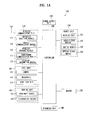
- FIG. 1A is a block diagram of a mobile terminal in accordance with the present disclosure
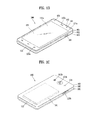
- FIGS. 1B and 1C are conceptual views of one example of the mobile terminal, viewed from different directions.
- the mobile terminal 100 is shown having components such as a wireless communication unit 110, an input unit 120, a sensing unit 140, an output unit 150, an interface unit 160, a memory 170, a controller 180, and a power supply unit 190. It is understood that implementing all of the illustrated components is not a requirement, and that greater or fewer components may alternatively be implemented.
- the mobile terminal 100 is shown having wireless communication unit 110 configured with several commonly implemented components.
- the wireless communication unit 110 typically includes one or more components which permit wireless communication between the mobile terminal 100 and a wireless communication system or network within which the mobile terminal is located.
- the wireless communication unit 110 typically includes one or more modules which permit communications such as wireless communications between the mobile terminal 100 and a wireless communication system, communications between the mobile terminal 100 and another mobile terminal, communications between the mobile terminal 100 and an external server. Further, the wireless communication unit 110 typically includes one or more modules which connect the mobile terminal 100 to one or more networks. To facilitate such communications, the wireless communication unit 110 includes one or more of a broadcast receiving module 111, a mobile communication module 112, a wireless Internet module 113, a short-range communication module 114, and a location information module 115.
- the input unit 120 includes a camera 121 for obtaining images or video, a microphone 122, which is one type of audio input device for inputting an audio signal, and a user input unit 123 (for example, a touch key, a push key, a mechanical key, a soft key, and the like) for allowing a user to input information.
- Data for example, audio, video, image, and the like
- controller 180 may analyze and process data (for example, audio, video, image, and the like) according to device parameters, user commands, and combinations thereof.
- the sensing unit 140 is typically implemented using one or more sensors configured to sense internal information of the mobile terminal, the surrounding environment of the mobile terminal, user information, and the like.
- the sensing unit 140 is shown having a proximity sensor 141 and an illumination sensor 142.
- the sensing unit 140 may alternatively or additionally include other types of sensors or devices, such as a touch sensor, an acceleration sensor, a magnetic sensor, a G-sensor, a gyroscope sensor, a motion sensor, an RGB sensor, an infrared (IR) sensor, a finger scan sensor, a ultrasonic sensor, an optical sensor (for example, camera 121), a microphone 122, a battery gauge, an environment sensor (for example, a barometer, a hygrometer, a thermometer, a radiation detection sensor, a thermal sensor, and a gas sensor, among others), and a chemical sensor (for example, an electronic nose, a health care sensor, a biometric sensor, and the like), to name a few.
- the mobile terminal 100 may be configured to utilize information obtained from sensing unit 140, and in particular, information obtained from one or more sensors of the sensing unit 140, and combinations thereof.
- the output unit 150 is typically configured to output various types of information, such as audio, video, tactile output, and the like.
- the output unit 150 is shown having a display unit 151, an audio output module 152, a haptic module 153, and an optical output module 154.
- the display unit 151 may have an inter-layered structure or an integrated structure with a touch sensor in order to facilitate a touch screen.
- the touch screen may provide an output interface between the mobile terminal 100 and a user, as well as function as the user input unit 123 which provides an input interface between the mobile terminal 100 and the user.
- the interface unit 160 serves as an interface with various types of external devices that can be coupled to the mobile terminal 100.
- the interface unit 160 may include any of wired or wireless ports, external power supply ports, wired or wireless data ports, memory card ports, ports for connecting a device having an identification module, audio input/output (I/O) ports, video I/O ports, earphone ports, and the like.
- the mobile terminal 100 may perform assorted control functions associated with a connected external device, in response to the external device being connected to the interface unit 160.
- the memory 170 is typically implemented to store data to support various functions or features of the mobile terminal 100.
- the memory 170 may be configured to store application programs executed in the mobile terminal 100, data or instructions for operations of the mobile terminal 100, and the like. Some of these application programs may be downloaded from an external server via wireless communication. Other application programs may be installed within the mobile terminal 100 at time of manufacturing or shipping, which is typically the case for basic functions of the mobile terminal 100 (for example, receiving a call, placing a call, receiving a message, sending a message, and the like). It is common for application programs to be stored in the memory 170, installed in the mobile terminal 100, and executed by the controller 180 to perform an operation (or function) for the mobile terminal 100.
- the controller 180 typically functions to control overall operation of the mobile terminal 100, in addition to the operations associated with the application programs.
- the controller 180 may provide or process information or functions appropriate for a user by processing signals, data, information and the like, which are input or output by the various components depicted in Fig. 1A , or activating application programs stored in the memory 170.
- the controller 180 controls some or all of the components illustrated in FIGS. 1A-1C according to the execution of an application program that have been stored in the memory 170.
- the power supply unit 190 can be configured to receive external power or provide internal power in order to supply appropriate power required for operating elements and components included in the mobile terminal 100.
- the power supply unit 190 may include a battery, and the battery may be configured to be embedded in the terminal body, or configured to be detachable from the terminal body.
- the broadcast receiving module 111 is typically configured to receive a broadcast signal and/or broadcast associated information from an external broadcast managing entity via a broadcast channel.
- the broadcast channel may include a satellite channel, a terrestrial channel, or both.
- two or more broadcast receiving modules 111 may be utilized to facilitate simultaneously receiving of two or more broadcast channels, or to support switching among broadcast channels.
- the broadcast managing entity may be implemented using a server or system which generates and transmits a broadcast signal and/or broadcast associated information, or a server which receives a pre-generated broadcast signal and/or broadcast associated information, and sends such items to the mobile terminal.
- the broadcast signal may be implemented using any of a TV broadcast signal, a radio broadcast signal, a data broadcast signal, and combinations thereof, among others.
- the broadcast signal in some cases may further include a data broadcast signal combined with a TV or radio broadcast signal.
- the broadcast signal may be encoded according to any of a variety of technical standards or broadcasting methods (for example, International Organization for Standardization (ISO), International Electrotechnical Commission (IEC), Digital Video Broadcast (DVB), Advanced Television Systems Committee (ATSC), and the like) for transmission and reception of digital broadcast signals.
- the broadcast receiving module 111 can receive the digital broadcast signals using a method appropriate for the transmission method utilized.
- broadcast associated information may include information associated with a broadcast channel, a broadcast program, a broadcast event, a broadcast service provider, or the like.
- the broadcast associated information may also be provided via a mobile communication network, and in this case, received by the mobile communication module 112.
- broadcast associated information may be implemented in various formats.
- broadcast associated information may include an Electronic Program Guide (EPG) of Digital Multimedia Broadcasting (DMB), an Electronic Service Guide (ESG) of Digital Video Broadcast-Handheld (DVB-H), and the like.
- EPG Electronic Program Guide
- ESG Electronic Service Guide
- Broadcast signals and/or broadcast associated information received via the broadcast receiving module 111 may be stored in a suitable device, such as a memory 170.
- the mobile communication module 112 can transmit and/or receive wireless signals to and from one or more network entities.
- a network entity include a base station, an external mobile terminal, a server, and the like.
- Such network entities form part of a mobile communication network, which is constructed according to technical standards or communication methods for mobile communications (for example, Global System for Mobile Communication (GSM), Code Division Multi Access (CDMA), CDMA2000(Code Division Multi Access 2000), EV-DO(Enhanced Voice-Data Optimized or Enhanced Voice-Data Only), Wideband CDMA (WCDMA), High Speed Downlink Packet access (HSDPA), HSUPA(High Speed Uplink Packet Access), Long Term Evolution (LTE), LTE-A(Long Term Evolution-Advanced), and the like).
- Examples of wireless signals transmitted and/or received via the mobile communication module 112 include audio call signals, video (telephony) call signals, or various formats of data to support communication of text and multimedia messages.
- the wireless Internet module 113 is configured to facilitate wireless Internet access. This module may be internally or externally coupled to the mobile terminal 100. The wireless Internet module 113 may transmit and/or receive wireless signals via communication networks according to wireless Internet technologies.
- wireless Internet access examples include Wireless LAN (WLAN), Wireless Fidelity (Wi-Fi), Wi-Fi Direct, Digital Living Network Alliance (DLNA), Wireless Broadband (WiBro), Worldwide Interoperability for Microwave Access (WiMAX), High Speed Downlink Packet Access (HSDPA), HSUPA(High Speed Uplink Packet Access), Long Term Evolution (LTE), LTE-A(Long Term Evolution-Advanced), and the like.
- the wireless Internet module 113 may transmit/receive data according to one or more of such wireless Internet technologies, and other Internet technologies as well.
- the wireless Internet module 113 when the wireless Internet access is implemented according to, for example, WiBro, HSDPA,HSUPA, GSM, CDMA, WCDMA, LTE, LTE-A and the like, as part of a mobile communication network, the wireless Internet module 113 performs such wireless Internet access. As such, the Internet module 113 may cooperate with, or function as, the mobile communication module 112.
- the short-range communication module 114 is configured to facilitate short-range communications. Suitable technologies for implementing such short-range communications include BLUETOOTHTM, Radio Frequency IDentification (RFID), Infrared Data Association (IrDA), Ultra-WideBand (UWB), ZigBee, Near Field Communication (NFC), Wireless-Fidelity (Wi-Fi), Wi-Fi Direct, Wireless USB(Wireless Universal Serial Bus), and the like.
- the short-range communication module 114 in general supports wireless communications between the mobile terminal 100 and a wireless communication system, communications between the mobile terminal 100 and another mobile terminal 100, or communications between the mobile terminal and a network where another mobile terminal 100 (or an external server) is located, via wireless area networks.
- One example of the wireless area networks is a wireless personal area networks.
- another mobile terminal (which may be configured similarly to mobile terminal 100) may be a wearable device, for example, a smart watch, a smart glass or a head mounted display (HMD), which is able to exchange data with the mobile terminal 100 (or otherwise cooperate with the mobile terminal 100).
- the short-range communication module 114 may sense or recognize the wearable device, and permit communication between the wearable device and the mobile terminal 100.
- the controller 180 when the sensed wearable device is a device which is authenticated to communicate with the mobile terminal 100, the controller 180, for example, may cause transmission of data processed in the mobile terminal 100 to the wearable device via the short-range communication module 114.
- a user of the wearable device may use the data processed in the mobile terminal 100 on the wearable device. For example, when a call is received in the mobile terminal 100, the user may answer the call using the wearable device. Also, when a message is received in the mobile terminal 100, the user can check the received message using the wearable device.
- the location information module 115 is generally configured to detect, calculate, derive or otherwise identify a position of the mobile terminal.
- the location information module 115 includes a Global Position System (GPS) module, a Wi-Fi module, or both. If desired, the location information module 115 may alternatively or additionally function with any of the other modules of the wireless communication unit 110 to obtain data related to the position of the mobile terminal.
- GPS Global Position System
- Wi-Fi Wireless Fidelity
- a position of the mobile terminal may be acquired using a signal sent from a GPS satellite.
- a position of the mobile terminal can be acquired based on information related to a wireless access point (AP) which transmits or receives a wireless signal to or from the Wi-Fi module.
- AP wireless access point
- the input unit 120 may be configured to permit various types of input to the mobile terminal 120. Examples of such input include audio, image, video, data, and user input.
- Image and video input is often obtained using one or more cameras 121. Such cameras 121 may process image frames of still pictures or video obtained by image sensors in a video or image capture mode. The processed image frames can be displayed on the display unit 151 or stored in memory 170.
- the cameras 121 may be arranged in a matrix configuration to permit a plurality of images having various angles or focal points to be input to the mobile terminal 100. As another example, the cameras 121 may be located in a stereoscopic arrangement to acquire left and right images for implementing a stereoscopic image.
- the microphone 122 is generally implemented to permit audio input to the mobile terminal 100.
- the audio input can be processed in various manners according to a function being executed in the mobile terminal 100.
- the microphone 122 may include assorted noise removing algorithms to remove unwanted noise generated in the course of receiving the external audio.
- the user input unit 123 is a component that permits input by a user. Such user input may enable the controller 180 to control operation of the mobile terminal 100.
- the user input unit 123 may include one or more of a mechanical input element (for example, a key, a button located on a front and/or rear surface or a side surface of the mobile terminal 100, a dome switch, a jog wheel, a jog switch, and the like), or a touch-sensitive input, among others.
- the touch-sensitive input may be a virtual key or a soft key, which is displayed on a touch screen through software processing, or a touch key which is located on the mobile terminal at a location that is other than the touch screen.
- the virtual key or the visual key may be displayed on the touch screen in various shapes, for example, graphic, text, icon, video, or a combination thereof.
- the sensing unit 140 is generally configured to sense one or more of internal information of the mobile terminal, surrounding environment information of the mobile terminal, user information, or the like.
- the controller 180 generally cooperates with the sending unit 140 to control operation of the mobile terminal 100 or execute data processing, a function or an operation associated with an application program installed in the mobile terminal based on the sensing provided by the sensing unit 140.
- the sensing unit 140 may be implemented using any of a variety of sensors, some of which will now be described in more detail.
- the proximity sensor 141 may include a sensor to sense presence or absence of an object approaching a surface, or an object located near a surface, by using an electromagnetic field, infrared rays, or the like without a mechanical contact.
- the proximity sensor 141 may be arranged at an inner region of the mobile terminal covered by the touch screen, or near the touch screen.
- the proximity sensor 141 may include any of a transmissive type photoelectric sensor, a direct reflective type photoelectric sensor, a mirror reflective type photoelectric sensor, a high-frequency oscillation proximity sensor, a capacitance type proximity sensor, a magnetic type proximity sensor, an infrared rays proximity sensor, and the like.
- the proximity sensor 141 can sense proximity of a pointer relative to the touch screen by changes of an electromagnetic field, which is responsive to an approach of an object with conductivity.
- the touch screen may also be categorized as a proximity sensor.
- proximity touch will often be referred to herein to denote the scenario in which a pointer is positioned to be proximate to the touch screen without contacting the touch screen.
- contact touch will often be referred to herein to denote the scenario in which a pointer makes physical contact with the touch screen.
- the proximity sensor 141 may sense proximity touch, and proximity touch patterns (for example, distance, direction, speed, time, position, moving status, and the like).
- controller 180 processes data corresponding to proximity touches and proximity touch patterns sensed by the proximity sensor 141, and cause output of visual information on the touch screen.
- the controller 180 can control the mobile terminal 100 to execute different operations or process different data according to whether a touch with respect to a point on the touch screen is either a proximity touch or a contact touch.
- a touch sensor can sense a touch applied to the touch screen, such as display unit 151, using any of a variety of touch methods. Examples of such touch methods include a resistive type, a capacitive type, an infrared type, and a magnetic field type, among others.
- the touch sensor may be configured to convert changes of pressure applied to a specific part of the display unit 151, or convert capacitance occurring at a specific part of the display unit 151, into electric input signals.
- the touch sensor may also be configured to sense not only a touched position and a touched area, but also touch pressure and/or touch capacitance.
- a touch object is generally used to apply a touch input to the touch sensor. Examples of typical touch objects include a finger, a touch pen, a stylus pen, a pointer, or the like.
- a touch controller When a touch input is sensed by a touch sensor, corresponding signals may be transmitted to a touch controller.
- the touch controller may process the received signals, and then transmit corresponding data to the controller 180.
- the controller 180 may sense which region of the display unit 151 has been touched.
- the touch controller may be a component separate from the controller 180, the controller 180, and combinations thereof.
- the controller 180 may execute the same or different controls according to a type of touch object that touches the touch screen or a touch key provided in addition to the touch screen. Whether to execute the same or different control according to the object which provides a touch input may be decided based on a current operating state of the mobile terminal 100 or a currently executed application program, for example.
- the touch sensor and the proximity sensor may be implemented individually, or in combination, to sense various types of touches.
- Such touches includes a short (or tap) touch, a long touch, a multi-touch, a drag touch, a flick touch, a pinch-in touch, a pinch-out touch, a swipe touch, a hovering touch, and the like.
- an ultrasonic sensor may be implemented to recognize position information relating to a touch object using ultrasonic waves.
- the controller 180 may calculate a position of a wave generation source based on information sensed by an illumination sensor and a plurality of ultrasonic sensors. Since light is much faster than ultrasonic waves, the time for which the light reaches the optical sensor is much shorter than the time for which the ultrasonic wave reaches the ultrasonic sensor. The position of the wave generation source may be calculated using this fact. For instance, the position of the wave generation source may be calculated using the time difference from the time that the ultrasonic wave reaches the sensor based on the light as a reference signal.
- the camera 121 typically includes at least one a camera sensor (CCD, CMOS etc.), a photo sensor (or image sensors), and a laser sensor.
- a camera sensor CCD, CMOS etc.
- a photo sensor or image sensors
- a laser sensor
- the photo sensor may be laminated on, or overlapped with, the display device.
- the photo sensor may be configured to scan movement of the physical object in proximity to the touch screen.
- the photo sensor may include photo diodes and transistors at rows and columns to scan content received at the photo sensor using an electrical signal which changes according to the quantity of applied light. Namely, the photo sensor may calculate the coordinates of the physical object according to variation of light to thus obtain position information of the physical object.
- the display unit 151 is generally configured to output information processed in the mobile terminal 100.
- the display unit 151 may display execution screen information of an application program executing at the mobile terminal 100 or user interface (UI) and graphic user interface (GUI) information in response to the execution screen information.
- UI user interface
- GUI graphic user interface
- the display unit 151 may be implemented as a stereoscopic display unit for displaying stereoscopic images.
- a typical stereoscopic display unit may employ a stereoscopic display scheme such as a stereoscopic scheme (a glass scheme), an auto-stereoscopic scheme (glassless scheme), a projection scheme (holographic scheme), or the like.
- a 3D stereoscopic image may include a left image (e.g., a left eye image) and a right image (e.g., a right eye image).
- a 3D stereoscopic imaging method can be divided into a top-down method in which left and right images are located up and down in a frame, an L-to-R (left-to-right or side by side) method in which left and right images are located left and right in a frame, a checker board method in which fragments of left and right images are located in a tile form, an interlaced method in which left and right images are alternately located by columns or rows, and a time sequential (or frame by frame) method in which left and right images are alternately displayed on a time basis.
- a left image thumbnail and a right image thumbnail can be generated from a left image and a right image of an original image frame, respectively, and then combined to generate a single 3D thumbnail image.
- thumbnail may be used to refer to a reduced image or a reduced still image.
- a generated left image thumbnail and right image thumbnail may be displayed with a horizontal distance difference there between by a depth corresponding to the disparity between the left image and the right image on the screen, thereby providing a stereoscopic space sense.
- a left image and a right image required for implementing a 3D stereoscopic image may be displayed on the stereoscopic display unit using a stereoscopic processing unit.
- the stereoscopic processing unit can receive the 3D image and extract the left image and the right image, or can receive the 2D image and change it into a left image and a right image.
- the audio output module 152 is generally configured to output audio data. Such audio data may be obtained from any of a number of different sources, such that the audio data may be received from the wireless communication unit 110 or may have been stored in the memory 170. The audio data may be output during modes such as a signal reception mode, a call mode, a record mode, a voice recognition mode, a broadcast reception mode, and the like. The audio output module 152 can provide audible output related to a particular function (e.g., a call signal reception sound, a message reception sound, etc.) performed by the mobile terminal 100. The audio output module 152 may also be implemented as a receiver, a speaker, a buzzer, or the like.
- a haptic module 153 can be configured to generate various tactile effects that a user feels, perceive, or otherwise experience.
- a typical example of a tactile effect generated by the haptic module 153 is vibration.
- the strength, pattern and the like of the vibration generated by the haptic module 153 can be controlled by user selection or setting by the controller. For example, the haptic module 153 may output different vibrations in a combining manner or a sequential manner.
- the haptic module 153 can generate various other tactile effects, including an effect by stimulation such as a pin arrangement vertically moving to contact skin, a spray force or suction force of air through a jet orifice or a suction opening, a touch to the skin, a contact of an electrode, electrostatic force, an effect by reproducing the sense of cold and warmth using an element that can absorb or generate heat, and the like.
- an effect by stimulation such as a pin arrangement vertically moving to contact skin, a spray force or suction force of air through a jet orifice or a suction opening, a touch to the skin, a contact of an electrode, electrostatic force, an effect by reproducing the sense of cold and warmth using an element that can absorb or generate heat, and the like.
- the haptic module 153 can also be implemented to allow the user to feel a tactile effect through a muscle sensation such as the user's fingers or arm, as well as transferring the tactile effect through direct contact. Two or more haptic modules 153 may be provided according to the particular configuration of the mobile terminal 100.
- An optical output module 154 can output a signal for indicating an event generation using light of a light source. Examples of events generated in the mobile terminal 100 may include message reception, call signal reception, a missed call, an alarm, a schedule notice, an email reception, information reception through an application, and the like.
- a signal output by the optical output module 154 may be implemented in such a manner that the mobile terminal emits monochromatic light or light with a plurality of colors.
- the signal output may be terminated as the mobile terminal senses that a user has checked the generated event, for example.
- the interface unit 160 serves as an interface for external devices to be connected with the mobile terminal 100.
- the interface unit 160 can receive data transmitted from an external device, receive power to transfer to elements and components within the mobile terminal 100, or transmit internal data of the mobile terminal 100 to such external device.
- the interface unit 160 may include wired or wireless headset ports, external power supply ports, wired or wireless data ports, memory card ports, ports for connecting a device having an identification module, audio input/output (I/O) ports, video I/O ports, earphone ports, or the like.
- the identification module may be a chip that stores various information for authenticating authority of using the mobile terminal 100 and may include a user identity module (UIM), a subscriber identity module (SIM), a universal subscriber identity module (USIM), and the like.
- the device having the identification module (also referred to herein as an "identifying device") may take the form of a smart card. Accordingly, the identifying device can be connected with the terminal 100 via the interface unit 160.
- the interface unit 160 can serve as a passage to allow power from the cradle to be supplied to the mobile terminal 100 or may serve as a passage to allow various command signals input by the user from the cradle to be transferred to the mobile terminal there through.
- Various command signals or power input from the cradle may operate as signals for recognizing that the mobile terminal is properly mounted on the cradle.
- the memory 170 can store programs to support operations of the controller 180 and store input/output data (for example, phonebook, messages, still images, videos, etc.).
- the memory 170 may store data related to various patterns of vibrations and audio which are output in response to touch inputs on the touch screen.
- the memory 170 may include one or more types of storage mediums including a Flash memory, a hard disk, a solid state disk, a silicon disk, a multimedia card micro type, a card-type memory (e.g., SD or DX memory, etc), a Random Access Memory (RAM), a Static Random Access Memory (SRAM), a Read-Only Memory (ROM), an Electrically Erasable Programmable Read-Only Memory (EEPROM), a Programmable Read-Only memory (PROM), a magnetic memory, a magnetic disk, an optical disk, and the like.
- the mobile terminal 100 may also be operated in relation to a network storage device that performs the storage function of the memory 170 over a network, such as the Internet.
- the controller 180 may typically control the general operations of the mobile terminal 100. For example, the controller 180 may set or release a lock state for restricting a user from inputting a control command with respect to applications when a status of the mobile terminal meets a preset condition.
- the controller 180 can also perform the controlling and processing associated with voice calls, data communications, video calls, and the like, or perform pattern recognition processing to recognize a handwriting input or a picture drawing input performed on the touch screen as characters or images, respectively.
- the controller 180 can control one or a combination of those components in order to implement various exemplary embodiments disclosed herein.
- the power supply unit 190 receives external power or provide internal power and supply the appropriate power required for operating respective elements and components included in the mobile terminal 100.
- the power supply unit 190 may include a battery, which is typically rechargeable or be detachably coupled to the terminal body for charging.
- the power supply unit 190 may include a connection port.
- the connection port may be configured as one example of the interface unit 160 to which an external charger for supplying power to recharge the battery is electrically connected.
- the power supply unit 190 may be configured to recharge the battery in a wireless manner without use of the connection port.
- the power supply unit 190 can receive power, transferred from an external wireless power transmitter, using at least one of an inductive coupling method which is based on magnetic induction or a magnetic resonance coupling method which is based on electromagnetic resonance.
- Various embodiments described herein may be implemented in a computer-readable medium, a machine-readable medium, or similar medium using, for example, software, hardware, or any combination thereof.
- the mobile terminal 100 is described with reference to a bar-type terminal body.
- the mobile terminal 100 may alternatively be implemented in any of a variety of different configurations. Examples of such configurations include watch-type, clip-type, glasses-type, or as a folder-type, flip-type, slide-type, swing-type, and swivel-type in which two and more bodies are combined with each other in a relatively movable manner, and combinations thereof. Discussion herein will often relate to a particular type of mobile terminal (for example, bar-type, watch-type, glasses-type, and the like). However, such teachings with regard to a particular type of mobile terminal will generally apply to other types of mobile terminals as well.
- the mobile terminal 100 will generally include a case (for example, frame, housing, cover, and the like) forming the appearance of the terminal.
- the case is formed using a front case 101 and a rear case 102.
- Various electronic components are incorporated into a space formed between the front case 101 and the rear case 102.
- At least one middle case may be additionally positioned between the front case 101 and the rear case 102.
- the display unit 151 is shown located on the front side of the terminal body to output information. As illustrated, a window 151a of the display unit 151 may be mounted to the front case 101 to form the front surface of the terminal body together with the front case 101.
- electronic components may also be mounted to the rear case 102.
- electronic components include a detachable battery 191, an identification module, a memory card, and the like.
- Rear cover 103 is shown covering the electronic components, and this cover may be detachably coupled to the rear case 102. Therefore, when the rear cover 103 is detached from the rear case 102, the electronic components mounted to the rear case 102 are externally exposed.
- the rear cover 103 when the rear cover 103 is coupled to the rear case 102, a side surface of the rear case 102 is partially exposed. In some cases, upon the coupling, the rear case 102 may also be completely shielded by the rear cover 103. In some embodiments, the rear cover 103 may include an opening for externally exposing a camera 121b or an audio output module 152b.
- the cases 101, 102, 103 may be formed by injection-molding synthetic resin or may be formed of a metal, for example, stainless steel (STS), aluminum (Al), titanium (Ti), or the like.
- STS stainless steel
- Al aluminum
- Ti titanium
- the mobile terminal 100 may be configured such that one case forms the inner space.
- a mobile terminal 100 having a uni-body is formed in such a manner that synthetic resin or metal extends from a side surface to a rear surface.
- the mobile terminal 100 may include a waterproofing unit (not shown) for preventing introduction of water into the terminal body.
- the waterproofing unit may include a waterproofing member which is located between the window 151a and the front case 101, between the front case 101 and the rear case 102, or between the rear case 102 and the rear cover 103, to hermetically seal an inner space when those cases are coupled.
- FIGS. 1B and 1C depict certain components as arranged on the mobile terminal. However, it is to be understood that alternative arrangements are possible and within the teachings of the instant disclosure. Some components may be omitted or rearranged.
- the first manipulation unit 123a may be located on another surface of the terminal body
- the second audio output module 152b may be located on the side surface of the terminal body.
- the display unit 151 outputs information processed in the mobile terminal 100.
- the display unit 151 may be implemented using one or more suitable display devices. Examples of such suitable display devices include a liquid crystal display (LCD), a thin film transistor-liquid crystal display (TFT-LCD), an organic light emitting diode (OLED), a flexible display, a 3-dimensional (3D) display, an e-ink display, and combinations thereof.
- the display unit 151 may be implemented using two display devices, which can implement the same or different display technology. For instance, a plurality of the display units 151 may be arranged on one side, either spaced apart from each other, or these devices may be integrated, or these devices may be arranged on different surfaces.
- the display unit 151 may also include a touch sensor which senses a touch input received at the display unit.
- the touch sensor may be configured to sense this touch and the controller 180, for example, may generate a control command or other signal corresponding to the touch.
- the content which is input in the touching manner may be a text or numerical value, or a menu item which can be indicated or designated in various modes.
- the touch sensor may be configured in a form of a film having a touch pattern, disposed between the window 151a and a display on a rear surface of the window 151a, or a metal wire which is patterned directly on the rear surface of the window 151a.
- the touch sensor may be integrally formed with the display.
- the touch sensor may be disposed on a substrate of the display or within the display.
- the display unit 151 may also form a touch screen together with the touch sensor.
- the touch screen may serve as the user input unit 123 (see FIG. 1A ). Therefore, the touch screen may replace at least some of the functions of the first manipulation unit 123a.
- the first audio output module 152a may be implemented in the form of a speaker to output voice audio, alarm sounds, multimedia audio reproduction, and the like.
- the window 151a of the display unit 151 will typically include an aperture to permit audio generated by the first audio output module 152a to pass.
- One alternative is to allow audio to be released along an assembly gap between the structural bodies (for example, a gap between the window 151a and the front case 101). In this case, a hole independently formed to output audio sounds may not be seen or is otherwise hidden in terms of appearance, thereby further simplifying the appearance and manufacturing of the mobile terminal 100.
- the optical output module 154 can be configured to output light for indicating an event generation. Examples of such events include a message reception, a call signal reception, a missed call, an alarm, a schedule notice, an email reception, information reception through an application, and the like.
- the controller can control the optical output unit 154 to stop the light output.
- the first camera 121a can process image frames such as still or moving images obtained by the image sensor in a capture mode or a video call mode.
- the processed image frames can then be displayed on the display unit 151 or stored in the memory 170.
- the first and second manipulation units 123a and 123b are examples of the user input unit 123, which may be manipulated by a user to provide input to the mobile terminal 100.
- the first and second manipulation units 123a and 123b may also be commonly referred to as a manipulating portion, and may employ any tactile method that allows the user to perform manipulation such as touch, push, scroll, or the like.
- the first and second manipulation units 123a and 123b may also employ any non-tactile method that allows the user to perform manipulation such as proximity touch, hovering, or the like.
- FIG. 1B illustrates the first manipulation unit 123a as a touch key, but possible alternatives include a mechanical key, a push key, a touch key, and combinations thereof.
- Input received at the first and second manipulation units 123a and 123b may be used in various ways.
- the first manipulation unit 123a may be used by the user to provide an input to a menu, home key, cancel, search, or the like
- the second manipulation unit 123b may be used by the user to provide an input to control a volume level being output from the first or second audio output modules 152a or 152b, to switch to a touch recognition mode of the display unit 151, or the like.
- a rear input unit may be located on the rear surface of the terminal body.
- the rear input unit can be manipulated by a user to provide input to the mobile terminal 100.
- the input may be used in a variety of different ways.
- the rear input unit may be used by the user to provide an input for power on/off, start, end, scroll, control volume level being output from the first or second audio output modules 152a or 152b, switch to a touch recognition mode of the display unit 151, and the like.
- the rear input unit may be configured to permit touch input, a push input, or combinations thereof.
- the rear input unit may be located to overlap the display unit 151 of the front side in a thickness direction of the terminal body.
- the rear input unit may be located on an upper end portion of the rear side of the terminal body such that a user can easily manipulate it using a forefinger when the user grabs the terminal body with one hand.
- the rear input unit can be positioned at most any location of the rear side of the terminal body.
- Embodiments that include the rear input unit may implement some or all of the functionality of the first manipulation unit 123a in the rear input unit. As such, in situations where the first manipulation unit 123a is omitted from the front side, the display unit 151 can have a larger screen.
- the mobile terminal 100 may include a finger scan sensor which scans a user's fingerprint.
- the controller 180 can then use fingerprint information sensed by the finger scan sensor as part of an authentication procedure.
- the finger scan sensor may also be installed in the display unit 151 or implemented in the user input unit 123.
- the microphone 122 is shown located at an end of the mobile terminal 100, but other locations are possible. If desired, multiple microphones may be implemented, with such an arrangement permitting the receiving of stereo sounds.
- the interface unit 160 may serve as a path allowing the mobile terminal 100 to interface with external devices.
- the interface unit 160 may include one or more of a connection terminal for connecting to another device (for example, an earphone, an external speaker, or the like), a port for near field communication (for example, an Infrared Data Association (IrDA) port, a Bluetooth port, a wireless LAN port, and the like), or a power supply terminal for supplying power to the mobile terminal 100.
- the interface unit 160 may be implemented in the form of a socket for accommodating an external card, such as Subscriber Identification Module (SIM), User Identity Module (UIM), or a memory card for information storage.
- SIM Subscriber Identification Module
- UIM User Identity Module
- the second camera 121b is shown located at the rear side of the terminal body and includes an image capturing direction that is substantially opposite to the image capturing direction of the first camera unit 121a. If desired, second camera 121a may alternatively be located at other locations, or made to be moveable, in order to have a different image capturing direction from that which is shown.
- the second camera 121b can include a plurality of lenses arranged along at least one line.
- the plurality of lenses may also be arranged in a matrix configuration.
- the cameras may be referred to as an "array camera.”
- the second camera 121b is implemented as an array camera, images may be captured in various manners using the plurality of lenses and images with better qualities.
- a flash 124 is shown adjacent to the second camera 121b.
- the flash 124 may illuminate the subject.
- the second audio output module 152b can be located on the terminal body.
- the second audio output module 152b may implement stereophonic sound functions in conjunction with the first audio output module 152a, and may be also used for implementing a speaker phone mode for call communication.
- At least one antenna for wireless communication may be located on the terminal body.
- the antenna may be installed in the terminal body or formed by the case.
- an antenna which configures a part of the broadcast receiving module 111 may be retractable into the terminal body.
- an antenna may be formed using a film attached to an inner surface of the rear cover 103, or a case that includes a conductive material.
- a power supply unit 190 for supplying power to the mobile terminal 100 may include a battery 191, which is mounted in the terminal body or detachably coupled to an outside of the terminal body.
- the battery 191 may receive power via a power source cable connected to the interface unit 160.
- the battery 191 can be recharged in a wireless manner using a wireless charger. Wireless charging may be implemented by magnetic induction or electromagnetic resonance.
- the rear cover 103 is shown coupled to the rear case 102 for shielding the battery 191, to prevent separation of the battery 191, and to protect the battery 191 from an external impact or from foreign material.
- the rear case 103 may be detachably coupled to the rear case 102.
- An accessory for protecting an appearance or assisting or extending the functions of the mobile terminal 100 can also be provided on the mobile terminal 100.
- a cover or pouch for covering or accommodating at least one surface of the mobile terminal 100 may be provided.
- the cover or pouch may cooperate with the display unit 151 to extend the function of the mobile terminal 100.
- a touch pen for assisting or extending a touch input to a touch screen is another example of the accessory.
- FIG. 2 is a perspective view illustrating one example of a watch-type mobile terminal 200 in accordance with another exemplary embodiment.
- the watch-type mobile terminal 200 includes a main body 201 with a display unit 351 and a band 202 connected to the main body 201 to be wearable on a wrist.
- mobile terminal 200 may be configured to include features that are the same or similar to that of mobile terminal 100 of FIGS. 1A-1C .
- the main body 201 may include a case having a certain appearance. As illustrated, the case may include a first case 201a and a second case 201b cooperatively defining an inner space for accommodating various electronic components. Other configurations are possible. For instance, a single case may alternatively be implemented, with such a case being configured to define the inner space, thereby implementing a mobile terminal 200 with a uni-body.
- the watch-type mobile terminal 200 can perform wireless communication, and an antenna for the wireless communication can be installed in the main body 201.
- the antenna may extend its function using the case.
- a case including a conductive material may be electrically connected to the antenna to extend a ground area or a radiation area.
- the display unit 351 is shown located at the front side of the main body 201 so that displayed information is viewable to a user.
- the display unit 351 includes a touch sensor so that the display unit can function as a touch screen.
- window 351a is positioned on the first case 201a to form a front surface of the terminal body together with the first case 201a.
- the illustrated embodiment includes audio output module 352, a camera 321, a microphone 322, and a user input unit 323 positioned on the main body 201.
- the display unit 351 is implemented as a touch screen, additional function keys may be minimized or eliminated.
- the user input unit 323 may be omitted.
- the band 202 is commonly worn on the user's wrist and may be made of a flexible material for facilitating wearing of the device.
- the band 202 may be made of fur, rubber, silicon, synthetic resin, or the like.
- the band 202 may also be configured to be detachable from the main body 201. Accordingly, the band 202 may be replaceable with various types of bands according to a user's preference.
- the band 202 may be used for extending the performance of the antenna.
- the band may include therein a ground extending portion (not shown) electrically connected to the antenna to extend a ground area.
- the band 202 may include fastener 202a.
- the fastener 202a may be implemented into a buckle type, a snap-fit hook structure, a Velcro® type, or the like, and include a flexible section or material.
- the drawing illustrates an example that the fastener 202a is implemented using a buckle.
- a mobile terminal 100 according to the present invention is the watch type mobile terminal shown in FIG. 2 for example. And, assume that the mobile terminal 100 according to the present invention includes at least one of the components shown in FIGs. 1A to 1C . In particular, the mobile terminal 100 according to the present invention can be assumed as including the wireless communication unit 110, the sensing unit 140, the display unit 151 and the controller 180.
- the mobile terminal 100 can receive a user's gesture input based on a sensing signal of the sensing unit 140. In doing so, the controller 180 is able to determine what kind of a gesture input is received through at least one of factors including a moving distance of the mobile terminal 100, a rotation angle of the mobile terminal 100 and a speed of the mobile terminal 100.
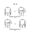
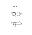
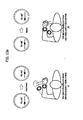
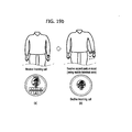
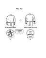
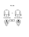
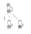
- FIGs. 3A to 3C are diagrams for examples of various gesture inputs.
- the mobile terminal 100 can receive a gesture input performed in a manner that a hand having a watch type mobile terminal worn thereon is stretched toward a floor and then moves by being folded toward a body of a user.
- the mobile terminal 100 can receive a gesture input performed in a manner of stretching out a hand folded toward a user body.
- the mobile terminal 100 can receive a gesture input performed in a manner of twisting a wrist on which a watch type mobile terminal is worn.
- the mobile terminal 100 can receive a gesture input performed in a manner of swinging a hand on which a watch type mobile terminal is worn.
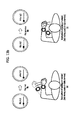
- the mobile terminal 100 can receive a gesture input of moving the mobile terminal 100 in a short distance toward or far away from a user body.
- the mobile terminal 100 can receive a small gesture input by sensing a muscular movement of a wrist part on which the mobile terminal 100 is worn.
- the mobile terminal can include a magnetic sensor configured to sense a magnetic variation in accordance with a movement of muscle, a pressure sensor configured to sense a pressure applied by a muscular movement, a ultrasonic wave sensor configured to sense a muscular movement by emitting ultrasonic waves and then sensing the reflected ultrasonic waves, and the like.
- a magnetic sensor configured to sense a magnetic variation in accordance with a movement of muscle
- a pressure sensor configured to sense a pressure applied by a muscular movement
- a ultrasonic wave sensor configured to sense a muscular movement by emitting ultrasonic waves and then sensing the reflected ultrasonic waves, and the like.
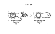
- the mobile terminal 100 can receive a gesture input performed in a manner of spreading two fingers (e.g., a thumb and an index finger, etc.).
- the mobile terminal 100 can receive a gesture input performed in a manner of narrowing two fingers (e.g., a thumb and an index finger, etc.).
- the controller 180 can further consider a moving speed of the mobile terminal 100. In particular, when the mobile terminal 100 is moved or rotated, if a moving speed of the mobile terminal 100 is equal to or higher than a prescribed speed, it can be determined as a gesture input. On the other hand, if a moving speed of the mobile terminal 100 is lower than the prescribed speed, it can be determined as not a gesture input.
- Various gesture inputs shown in FIGs. 3A to 3C can be sorted into a first type gesture and a second type gesture based on at least one of a moving distance of the mobile terminal 100, a rotated angle of the mobile terminal 100 and a moving speed of the mobile terminal 100.
- the first type gesture may include an action of moving the mobile terminal 100 of the watch type worn on a wrist in a distance equal to or greater than a prescribed distance or an action of rotating the mobile terminal 100 of the watch type worn on a wrist at an angle equal to or greater than a prescribed angle while worn on a wrist.
- FIG. 3A the first type gesture may include an action of moving the mobile terminal 100 of the watch type worn on a wrist in a distance equal to or greater than a prescribed distance or an action of rotating the mobile terminal 100 of the watch type worn on a wrist at an angle equal to or greater than a prescribed angle while worn on a wrist.
- the second type gesture may include an action of moving the mobile terminal 100 of the watch type worn on a wrist in a distance smaller than a prescribed distance or an action of rotating the mobile terminal 100 of the watch type worn on a wrist at an angle smaller than a prescribed angle.
- the second type gesture may include an action of moving finger(s) of a hand on which the mobile terminal 100 is worn.
- the mobile terminal 100 can control a displayed content or an operation mode to be changed.
- the controller 180 can change a displayed content in a manner of controlling the display unit 151 to switch to a screen for checking a detailed history of an event in the course of outputting a home screen (or a lock screen), controlling the display unit 151 to output a prescribed application in the course of outputting a home screen (or a lock screen)m controlling the display unit 151 to output a second application in the course outputting a first application, or the like.
- the controller 180 while the controller 180 operates in a read mode for checking an event content by displaying a detailed information of an event, if the first type gesture is inputted, the controller 180 can change an operation mode of the mobile terminal 100 into a call mode or a write mode (e.g., a text inputtable state, etc.).
- a call mode e.g., a text inputtable state, etc.
- the mobile terminal 100 can control a control operation, which is appropriate for a currently running application, to be performed without changing a displayed content.
- FIG. 4 is a flowchart for an operation of a mobile 100 terminal according to the present invention.
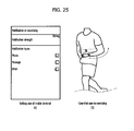
- the controller 180 cancels the power saving mode of the mobile terminal 100 and controls a current time to be outputted through the display unit 151 [S403].
- the power saving mode maintains the display unit 151 in turned-off (OFF) state to reduce a power consumption of the mobile terminal 100.
- the mobile terminal 100 can enter the power saving mode. For instance, if an input is not applied to the mobile terminal 100 for a prescribed time or a user input for entering the power saving mode is received, the mobile terminal 100 can enter the power saving mode. For another instance, if an event occurs in the mobile terminal 100 or a user input for cancelling the power saving mode is received, the power saving mode can be cancelled.
- FIG. 5 is a diagram for one example of cancelling a power saving mode of a mobile terminal if a first type gesture is inputted.
- the display unit 151 maintains an OFF state.
- the controller 180 cancels the power saving mode of the mobile terminal 100 and is able to control a current time information to be displayed through the display unit 151.
- the first type gesture includes an action of pulling up a hand having the mobile terminal 100 worn thereon toward a user body.
- the controller 180 can control a detailed information of the event to be displayed through the display unit 151 [S405].
- the event can include one of a reception of a message (e.g., a text message, an instant message, a push message, etc.), a presence of a missed absent call, a reception of an email, a case of meeting an alarm generation condition (e.g., a case that a current time is an alarm time, a case that a current time is a time for starting a pre-registered schedule, etc.), and the like.
- the detail information (or content) of the event may include one of a detailed content of a message (e.g., a text content of a text message, a text content of an instant message, etc.), a phone number of a missed incoming call, a detailed content of an email, an alarm content (e.g., an alarm time, a detailed content of a pre-registered schedule, etc.), and the like.
- a detailed content of a message e.g., a text content of a text message, a text content of an instant message, etc.
- an alarm content e.g., an alarm time, a detailed content of a pre-registered schedule, etc.
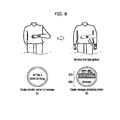
- FIG. 6 is a diagram for one example of displaying detailed information of an event if a first type gesture is inputted.
- an event occurs, like the example shown in FIG. 6 (a) , the controller 180 is able to control a feedback to be outputted while displaying an indicator indicating that an event has occurred.
- an information indicating the occurrence of the event includes a guide text indicating that a message has been received.
- the feedback can be implemented with vibration or sound, by which the present invention is non-limited.
- the controller 180 can control a detailed information of the event to be displayed.
- the first type gesture input includes a user's action of pulling up an arm toward a user's body. As the first type gesture is inputted, the detailed content of the received message is displayed.
- the controller 180 cancels the power saving mode and is also able to control an indicator, which indicates that the event has occurred, to be outputted.
- FIG. 7 is a diagram for one example of outputting an indicator indicating an event occurrence if a first type gesture is inputted.
- the controller 180 If a prescribed time elapses since the occurrence of the vent, like the example shown in FIG. 7 (b) , the controller 180 enters a power saving mode and is then able to turn off the display unit 151. Thereafter, if a first type gesture is inputted, like the example shown in FIG. 7 (c) , the controller 180 can control an indicator, which indicates that the event has occurred, to be outputted.
- the controller 180 may be able to display a detailed information of the event.
- the controller 180 can respond to the occurring event [S407].
- the controller 180 can make a phone call to the corresponding number or can control a message composing screen, which is provided to compose a message to send to the corresponding phone number, to be displayed.
- the controller 180 can control a message composing screen, which is provided to compose a reply to a counterpart having sent the message, to be displayed or can make a phone call to the counterpart having sent the message.
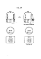
- FIG. 8 is a diagram for an operation of a mobile terminal if a first type gesture is inputted in the course of displaying a detailed information of an event.
- the controller 180 can control a message composing screen, which is provided to compose a reply to a counterpart having sent the message, to be displayed.
- the message composing screen may include a text body region 810 for displaying an inputted content and a keypad region 820 usable for inputting a text, by which the present invention is non-limited.
- a gesture input for composing a message reply may be different from a gesture input for making a phone call.
- the controller 180 can perform a scroll on the display unit 15 to control a content, which was not displayed on the display unit 151 in the detailed content of the event, to be displayed or to control a detailed content of a next event to be displayed.
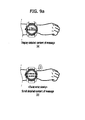
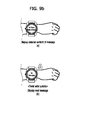
- FIG. 9A and FIG. 9B are diagrams for example of an operation of a mobile terminal if a second type gesture is inputted.
- FIG. 9A (a) and FIG. 9A (b) assume that a detailed content of a message is currently displayed through the display unit 151.
- While the detailed content of the message is displayed, like the example shown in FIG. 9A (b) , if a gesture of twisting a wrist having the mobile terminal 100 worn thereon is inputted and an input speed (e.g., a moving speed of the mobile terminal 100, etc.) of the gesture is smaller than a prescribed speed, the controller 180 can scroll the detailed content of the message in response to the gesture input. If the wrist is twisted in a top direction of the display unit 151, the controller 180 can scroll the detailed content of the message in a bottom direction (or the top direction). If the wrist is twisted in the bottom direction of the display unit 151, the controller 180 can scroll the detailed content of the message in the top direction (or the bottom direction).
- an input speed e.g., a moving speed of the mobile terminal 100, etc.
- While the detailed content of the message is displayed, like the example shown in FIG. 9B (b) , if a gesture of twisting a wrist having the mobile terminal 100 worn thereon is inputted and an input speed of the gesture is equal to or greater than a prescribed speed, the controller 180 can control a detailed content of a next (or previous) message to be displayed in response to the gesture input. If the wrist is twisted in a top direction of the display unit 151, the controller 180 can control the detailed content of the next (ore previous) message to be displayed. If the wrist is twisted in the bottom direction of the display unit 151, the controller 180 can control the detailed content of the previous (or next) message to be displayed.
- the controller 180 can enlarge or reduce an output of the display unit 151.
- FIG. 10 is a diagram for example of an operation of the mobile terminal 100 if a second type gesture is inputted.
- a gesture input of adjusting a distance between two fingers e.g., a thumb and an index finger, etc.
- the controller 180 can control a sound, which corresponds to TTS (text to sound) conversion of the detailed content of the event, to be outputted.
- TTS text to sound
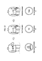
- FIG. 11 is a diagram for example of an operation of a mobile terminal if a second type gesture is inputted.
- FIG. 11 (a) , assume that a detailed content of a message is currently displayed through the display unit 151.
- the controller 180 can control a result from converting the detailed content (e.g., a text, etc.) of the message to a sound to be outputted in response to the gesture input. While the sound is outputted, if a gesture input of folding the fingers is received, the controller 190 can control the sound to stop being outputted.
- the detailed content e.g., a text, etc.
- the controller 180 can control a result from converting a detailed content of a next or previous message to a sound to be outputted while displaying the detailed content of the next or previous message. If the wrist is twisted in a top direction of the display unit 151, the detailed content of the next (or previous) message can be displayed. If the wrist is twisted in a bottom direction of the display unit 151, the detailed content of the previous (or next) message can be displayed.
- an action of twisting a wrist is a gesture input for scrolling or switching a message. And, whether to scroll or switch the message is determined depending on a speed of twisting the wrist. And, it is a matter of course that a gesture different from that shown in FIG. 9A or FIG. 9B can be assigned for scrolling or switching a message.
- FIG. 10 shows that a gesture of adjusting a distance between fingers is assigned to enlarge or reduce an output of the display unit 151, it is a matter of course that a gesture different from that shown in FIG. 10 can be used to enlarge or reduce an output of the display unit 151.
- the present invention is non-limited by the gesture input exemplarily shown in FIG. 11 .
- the controller 180 can run a prescribed application or can control a currently running application to be switched to a prescribed application [S408].
- FIG. 12 is a diagram for one example of running a prescribed application.
- the controller 180 can control a first application to be run [ FIG. 12 (b) ].
- the controller 180 stops running the first application and can control a second application to be run.
- each of the first application and the second application can be determined in order of running an application most recently or in order of being used frequently by a user.
- each of the first application and the second application can be determined in a manner of being randomly designated by a user.
- the controller 180 can perform a running control of the prescribed application in response to the second type gesture.
- the controller 180 can perform such an operation as a fast forward control (or a rewind control), a next/previous file play control, a play/pause control and the like.
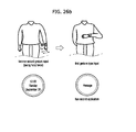
- FIG. 13A and FIG. 13B are diagrams for one example to describe an operation of a mobile terminal if a second type gesture is inputted in the course of running a music application.
- a music file is played, like the example shown in FIG. 13A (a) , if a gesture of shaking a hand having the mobile terminal 100 worn thereon from a user body outward is inputted and an input speed (i.e., a moving speed of the mobile terminal 100) of the gesture is smaller than a prescribed speed, the controller 180 can perform a fast forward operation (or a rewind operation) in response to the gesture input.
- a music file is played, like the example shown in FIG.
- the controller 180 can perform a rewind operation (or a fast forward operation) in response to the gesture input.
- While a music file is played like the example shown in FIG. 13B (a) , if a gesture of shaking a hand having the mobile terminal 100 worn thereon from a user body outward is inputted and an input speed of the gesture is equal to or greater than a prescribed speed, the controller 180 can start to play a next music file (or a previous music file) in response to the gesture input. On the contrary, while a music file is played, like the example shown in FIG.
- the controller 180 can start to play a previous music file (or a next music file) in response to the gesture input.
- the controller 180 can perform a play order shuffle operation.
- an application e.g., a music application, a video application, etc.
- a multimedia file e.g., a music file, a video file
- FIG. 14 is a diagram for one example to describe an operation of the mobile terminal 100 if a second type gesture is inputted in the course of running a music application.
- the controller 180 can change a play order of music file in response to the gesture input [ FIG. 14 (b) ].
- the controller 180 can play a multimedia file or stop (or pause) a play of the multimedia file.
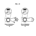
- FIG. 15 is a diagram for example of an operation of the mobile terminal 100 if a second type gesture is inputted.
- the controller 180 can control a multimedia file (e.g., a music file, a video file, etc.) to start to be played in response to the gesture input.
- a multimedia file e.g., a music file, a video file, etc.
- the controller 180 can control a play of the multimedia file to be stopped (or paused) in response to the gesture input.
- an action of shaking a hand from a user body outward or an action of shaking a hand toward a user body inward is to change a play time (i.e., a fast forward or a rewind) or to change a currently played multimedia file.
- a play time i.e., a fast forward or a rewind
- it is able to determine whether to change a play time of a multimedia file or whether to change a multimedia file.
- the present invention is non-limited by the gesture inputs shown in FIG. 13A and FIG. 13B .
- a gesture different from that of the example shown in FIG. 13A or FIG. 13B can be assigned for a multimedia file play time change or a multimedia file change.
- FIG. 16 is a diagram for another example of changing a play time of a multimedia file.
- the controller 180 can perform a fast forward action (or a rewind action).
- the controller 180 can perform a rewind action (or a fast forward action).
- FIG. 14 shows that an action of shaking a hand is a gesture input for shuffling a play order
- another gesture different from that shown in FIG. 14 can be assigned to a gesture input for shuffling a play order.
- a gesture different from that shown in FIG. 15 can be assigned to a gesture input for adjusting a play of a multimedia file.
- the controller 180 can change an operation mode of the mobile terminal 100 (e.g., enter a read mode for displaying a detailed information, switch to an input mode for inputting a text from a read mode, switch to a call mode for sending a call from a read mode, etc.) or can run an application of the mobile terminal 100.
- an operation mode of the mobile terminal 100 e.g., enter a read mode for displaying a detailed information, switch to an input mode for inputting a text from a read mode, switch to a call mode for sending a call from a read mode, etc.
- the controller 180 can control an appropriate control operation to be performed while maintaining a currently display content (i.e., maintaining a display of a detailed information of an event, maintaining a currently running application, etc.).
- the mobile terminal 100 when an event occurs, even if a second type gesture is inputted, the mobile terminal 100 according to the present invention can display a detailed information of the event. As the detailed information of the event is displayed in response to the second type gesture, it is able to prevent a user from inputting a first type gesture repeatedly.
- the controller 180 can cancel the power saving mode of the mobile terminal 100.
- an indicator indicating that the vent has occurred can be outputted together with a current time information as soon as the power saving mode of the mobile terminal 100 is cancelled. While the indicator is outputted, if a user attempts to check a detailed content of the event, as mentioned in the foregoing description with reference to FIG. 6 (a) , it may be necessary to input the first type gesture again.
- the mobile terminal 100 After the mobile terminal 100 has entered the power saving mode, it may be necessary for the user to repeatedly input the first type gesture twice in order to check the detailed content of the event. Yet, since the moving distance of the mobile terminal 100 is relatively long in case of the first type gesture, like the former examples shown in FIG. 3A and FIG. 3B , if the user is forced to input the first type gesture consecutively, it may cause inconvenience to the user.
- the mobile terminal 100 when an event occurs, even if a second type gesture is inputted, the mobile terminal 100 according to the present invention may be able to display a detailed information of the event.
- FIG. 17A and FIG. 17B are diagrams for one example of displaying a detailed information of an event if a second type gesture is inputted.
- the controller 180 can control an indicator indicating an occurrence of an event to be outputted. Thereafter, like the example shown in FIG. 17 (b) , if a gesture of swinging a hand having the mobile terminal 100 worn thereon once is inputted, the controller 180 can control a detailed information of the event to be displayed.
- the controller 180 can control a result from converting the detailed information of the event to audio or sound to be outputted while displaying the detailed information of the event. For instance, while an indicator indicating an occurrence of an event is outputted [ FIG. 17B (a) ], like the example shown in FIG. 17B (b) , if a gesture of swinging a hand having the mobile terminal 100 worn thereon twice is inputted, the controller 180 can control a result from converting a detailed information of the event to sound or audio to be outputted while displaying the detailed information of the event.
- FIG. 17A or FIG. 17B shows one example of displaying a detailed information of an event in response to a gesture of swinging a hand, by which a gesture input for displaying the detailed information of the event is non-limited.
- the mobile terminal 100 can change an operation mode of the mobile terminal 100. As the operation mode of the mobile terminal 100 is switched to a call mode or an input mode by the second type gesture, it is able to prevent a user from inputting a first type gesture repeatedly.
- FIG. 18 is a diagram for one example of changing an operation mode of the mobile terminal 100 if a second type gesture is inputted.
- the controller 180 can make a phone call to a counterpart having sent a message.
- the controller 180 can control a message composing screen for composing a reply to be displayed.
- FIG. 18 shows one example that an operation mode of the mobile terminal 100 is changed in response to a gesture of contacting two fingers with each other, by which a gesture input for changing an operation mode of the mobile terminal 100 is non-limited.
- the mobile terminal 100 can answer or decline the incoming call depending on a user's gesture input. For instance, when an incoming call is received, if a first type gesture is inputted, the controller 180 can answer the incoming call. When an incoming call is received, if a second type gesture is inputted, the controller 180 can decline the incoming call.
- FIGs. 19A to 19C are diagrams for examples of an operation of the mobile terminal 100 if a gesture input is received on receiving an incoming call.
- the controller 180 can control an information (e.g., an information on a counterpart having made the phone call, etc.), which indicates that the incoming call is received, and a feedback (e.g., vibration, sound, etc.) to be outputted. While the incoming call is received, if a gesture of lifting a hand having the mobile terminal 100 worn thereon up toward a user body is inputted, like the example shown in FIG. 19A (b) , the controller 180 can answer the incoming call.
- an information e.g., an information on a counterpart having made the phone call, etc.
- a feedback e.g., vibration, sound, etc.
- the controller 180 can decline the incoming call. As the incoming call is declined, while a presence of a missed call is notified, if a first type gesture (e.g., a gesture of lifting the hand having the mobile terminal 100 worn thereon up toward a user body, etc.) is inputted, like the example shown in FIG. 19B (c) , the controller 180 can control a detailed information of the declined phone call to be displayed.
- the detailed information of the declined phone call may include at least one of a name of counterpart having made the phone call, a phone number of the counterpart having made the phone call, and an information on an incoming call received time.
- the controller 180 can automatically send a message indicating that a user is unable to answer the phone call to the counterpart having made the phone call.
- the controller 180 can automatically send a message to an incoming call declined counterpart while declining the incoming call. Thereafter, if a first type gesture (e.g., a gesture of lifting the hand having the mobile terminal 100 worn thereon up toward a body) is inputted, like the example shown in FIG. 19C (c) , the controller 180 can control a detailed content of the message having sent to the counterpart to be displayed.
- a first type gesture e.g., a gesture of lifting the hand having the mobile terminal 100 worn thereon up toward a body
- the controller 180 can control a detailed content of the message having sent to the counterpart to be displayed.
- the controller 180 can output such an alarm as a vibration, a sound and the like. For instance, if a current time is a preset alarm time or a time at which a pre-registered schedule starts, the controller 180 can control at least one of a vibration, a sound and the like to be outputted.
- the controller 180 can control a detailed content of an alarm occurrence to be displayed. For instance, as a current time is an alarm time, when an alarm is outputted, if a first type gesture is inputted, the controller 180 can control a detailed information, which includes at least one of a name of a set alarm and a set alarm time, to be outputted.
- the controller 180 can control a detailed information, which includes at least one of a name of the pre-registered schedule, a time for starting a schedule and a schedule starting location, to be outputted.
- the controller 180 can end the output of the alarm or postpone the output of the alarm to start after a prescribed time [snooze].
- FIG. 20A and FIG. 20B are diagrams for an operation of a mobile terminal if a second type gesture is inputted on outputting an alarm.
- FIG. 20A as an alarm generation condition is met, while an alarm is outputted [ FIG. 20A (a) ], if a gesture of swinging the mobile terminal 100 is inputted, the controller 180 can control the alarm to stop being outputted [ FIG. 20A (b) ].
- FIG. 20B As an alarm generation condition is met, while an alarm is outputted [ FIG. 20B (a) ], if a gesture of rotating the mobile terminal 100 is inputted, the controller 180 can delay the alarm output after a prescribed time [ FIG. 20B (b) ].
- FIG. 20A and FIG. 20B show examples of controlling an alarm output through a gesture of swinging an arm or a gesture of rotating an arm, by which a gesture for controlling an alarm output is non-limited. For instance, various kinds of gestures can be used to control an alarm output.
- the mobile terminal 100 can change the settings of the mobile terminal 100.
- the controller 180 is able to adjust a vibration mode or an audio output mode in response to a gesture input.
- the controller 180 can adjust a volume or a brightness of the display unit 151 in response to a gesture input.
- FIG. 21 is a diagram for one example of adjusting a vibration mode or an audio output mode by a gesture input.
- the controller 180 can control an audio output mode and a vibration mode to be switched to each other.
- an audio output mode of the mobile terminal 100 is switched to a vibration mode.
- FIG. 22 is a diagram for one example of adjusting a brightness of a display unit.
- the controller 180 can control the brightness of the display unit 151 to increase (or decrease).
- the controller 180 can control the brightness of the display unit 151 to decrease (or increase).
- the controller 180 is able to adjust the settings of the mobile terminal in response to a gesture input.
- the gesture inputs shown in FIG. 21 and FIG. 22 are proposed just for clarity of the descriptions. In particular, it is a matter of course that other gesture inputs different from those shown in the drawings can apply to adjusting the settings of the mobile terminal 100.
- the mobile terminal 100 can unlock the display unit 151 through a user's gesture input.
- the controller 180 can unlock the display unit 151 by considering at least one of a finger motion, a count of a finger wag, and a location of a wagged finger.
- FIG. 23 is a diagram for one example of unlocking the display unit 151.
- an action of wagging an index finger once and then wagging a ring finger twice is set as a password.
- the controller 180 can set a state of the display unit 151 to a locked state until a password for unlocking the display unit 151 is inputted.
- the locked state means a state for authenticating a presence of authority for using the mobile terminal before accessing a content saved in the mobile terminal 100 or an application installed in the mobile terminal 100. If a state of the display unit 151 is set to the locked state, like the example shown in FIG. 23 (a) , the controller 180 can control a locked screen containing a current time information to be displayed.
- the controller 180 can determine whether the gesture input matches a preset password. For instance, if a gesture of wagging a thumb once and then wagging a ring finger twice is inputted, the controller 180 determines that the gesture matching the password is inputted and is then able to unlock the display unit 151. Once the display unit 151 is unlocked, the controller 180 controls an information, which has been displayed before the display unit 151 entered the locked state, to be displayed or, like the example shown in FIG. 23 (c) , can control a home screen to be displayed.
- the controller 180 can control a locked screen, which includes an indicator indicating a current time information and an occurrence of the event, to be displayed. In doing so, when a gesture input of wagging finger(s) is received, if the received gesture input matches a preset password, the controller 180 unlocks the display unit 151 and is also able to control a detailed information of the event to be displayed.
- the controller 180 can control a result from converting the detailed information of the event to audio or sound to be outputted as soon as outputs the detailed information of the event.
- the mobile terminal 100 sets a mode of the mobile terminal 100 to a power saving mode or can control the mobile terminal 100 to enter a normal mode from the power saving mode, through a user's gesture input. This is described in detail with reference to FIG. 24 as follows.
- FIG. 24 is a diagram for one example of switching a mode of a mobile terminal to a power saving mode.
- FIG. 24 assume that an action of wagging one of fingers twice consecutively is a gesture input for a power saving mode switching. While the display unit 151 is turned on, if a gesture input of wagging a random finger twice is received [ FIG. 24 (a) ], the controller 180 controls the mobile terminal 100 to enter a power saving mode and is able to control the display unit 151 to be turned off [ FIG. 24 (b) ].
- the controller 180 cancels the power saving mode and is able to control the display unit 151 to be turned on.
- the mobile terminal 100 can output a feedback in form of at least one of vibration and sound.
- the vibration is outputted in accordance with the event occurrence, if a user is moving vigorously (e.g., a user is exercising), it is difficult for the user to sense the vibration.
- the controller 180 determines that the user is moving vigorously, the controller 180 can control an output strength of the vibration to be automatically raised.
- the controller 180 can determine whether the user is moving vigorously based on such a sensing signal of the sensing unit 140 as a motion of the mobile terminal 100, a moving speed of the mobile terminal 100 and the like.
- the mobile terminal 100 can control a feedback for an event preset by a user to be outputted only.
- a user has preset a feedback to be outputted only if there is an incoming call in the course of exercising.
- the controller 180 output a feedback. If an event (e.g., a reception of a message, etc.) other than the preset event occurs, the controller 180 can skip the feedback output.
- the prescribed application may include a most recently run application or a most frequently used application.
- the controller 180 can determine an application, which is to be run by the first type gesture, based on a type of the second type gesture, a count of inputs of the second type gesture, an inputted duration of the second type gesture and the like.
- FIG. 26A and FIG. 26B are diagrams for one example of adjusting an application to run in response to an input count of a second type gesture.
- the controller 180 can control a first application (e.g., a music application in FIG. 26A ) to be run.
- a first application e.g., a music application in FIG. 26A
- the controller 180 can control a second application (e.g., a message application in FIG. 26B ) to be run.
- a second application e.g., a message application in FIG. 26B
- the controller 180 can determine an application, which is to be run, based on a second type gesture inputted before inputting a first type gesture.
- embodiments of the present invention provide various effects and/or features.
- the present invention provides a mobile terminal and controlling method thereof, by which user's convenience can be enhanced.
- the present invention is to provide a mobile terminal and controlling method thereof, by which the mobile terminal can be remotely controlled based on a user's gesture input.
- a user is facilitated to remotely control a mobile terminal in a manner that a gesture input for performing a content change or a mode change and a gesture input for performing a general control operation without the content change or the mode change are discriminated from each other depending on a type of a gesture input.
- the processor-readable media may include all kinds of recording devices in which data readable by a processor are stored.
- the processor-readable media may include ROM, RAM, CD-ROM, magnetic tapes, floppy discs, optical data storage devices, and the like for example and also include carrier-wave type implementations (e.g., transmission via Internet).
Abstract
Description
- The present invention relates to a mobile terminal, and more particularly, to a mobile terminal and controlling method thereof. Although the present invention is suitable for a wide scope of applications, it is particularly suitable for remotely controlling a mobile terminal of a watch type.
- Terminals may be generally classified as mobile/portable terminals or stationary terminals according to their mobility. Mobile terminals may also be classified as handheld terminals or vehicle mounted terminals according to whether or not a user can directly carry the terminal.
- Mobile terminals have become increasingly more functional. Examples of such functions include data and voice communications, capturing images and video via a camera, recording audio, playing music files via a speaker system, and displaying images and video on a display. Some mobile terminals include additional functionality which supports game playing, while other terminals are configured as multimedia players. More recently, mobile terminals have been configured to receive broadcast and multicast signals which permit viewing of content such as videos and television programs.
- Efforts are ongoing to support and increase the functionality of mobile terminals. Such efforts include software and hardware improvements, as well as changes and improvements in the structural components.
- In order to further enhance mobility and portability of a mobile terminal, many ongoing efforts are made to research and develop a mobile terminal of a wrist-wearable type like a watch. However, since a mobile terminal of a watch type is provided with a display unit in limited size, a user has difficulty in touching a screen of the watch type mobile terminal unlike a conventional mobile terminal. If a new input method for manipulating a mobile terminal of a watch type appropriately is developed, it is able to further facilitate manipulation of the watch type mobile terminal appropriately.
- Accordingly, embodiments of the present invention are directed to a mobile terminal and controlling method thereof that substantially obviate one or more problems due to limitations and disadvantages of the related art.
- An object of the present invention is to provide a mobile terminal and controlling method thereof, by which user's convenience can be enhanced.
- In particular, one object of the present invention is to provide a mobile terminal and controlling method thereof, by which the mobile terminal can be remotely controlled based on a user's gesture input.
- Another object of the present invention is to provide a mobile terminal and controlling method thereof, by which a user is facilitated to remotely control the mobile terminal in a manner that a gesture input for performing a content change or a mode change and a gesture input for performing a general control operation without the content change or the mode change are discriminated from each other depending on a type of a gesture input.
- Additional advantages, objects, and features of the invention will be set forth in the disclosure herein as well as the accompanying drawings. Such aspects may also be appreciated by those skilled in the art based on the disclosure herein.
- To achieve these objects and other advantages and in accordance with the purpose of the invention, as embodied and broadly described herein, a watch type mobile terminal according to the present invention may include a sensor, a display, and a controller configured to identify a first gesture input based on input received from the sensor, wherein the first gesture input is identified when the mobile terminal is moved or rotated, and cause the display to display detailed information of an event at the mobile terminal in response to identifying the first gesture input.
- In another aspect of the present invention, as embodied and broadly described herein, a method of controlling a watch type mobile terminal according to the present invention may include identifying a first gesture input based on input received from a sensor, where the first gesture input is identified when the mobile terminal is moved or rotated, and displaying detailed information of an event in response to identifying the first gesture input.
- Effects obtainable from the present invention may be non-limited by the above mentioned effect. And, other unmentioned effects can be clearly understood from the following description by those having ordinary skill in the technical field to which the present invention pertains.
- It is to be understood that both the foregoing general description and the following detailed description of the present invention are exemplary and explanatory and are intended to provide further explanation of the invention as claimed.
- The present invention will become more fully understood from the detailed description given herein below and the accompanying drawings, which are given by illustration only, and thus are not limitative of the present invention, and wherein:
-
FIG. 1A is a block diagram of a mobile terminal in accordance with the present disclosure; -
FIGS. 1B and 1C are conceptual views of one example of the mobile terminal, viewed from different directions; -
FIG. 2 is a perspective diagram for one example of a watch-type mobile terminal in accordance with another exemplary embodiment; -
FIGs. 3A to 3C are diagrams for examples of various gesture inputs; -
FIG. 4 is a flowchart for an operation of a mobile terminal according to the present invention; -
FIG. 5 is a diagram for one example of cancelling a power saving mode of a mobile terminal if a first type gesture is inputted; -
FIG. 6 is a diagram for one example of displaying detailed information of an event if a first type gesture is inputted; -
FIG. 7 is a diagram for one example of outputting an indicator indicating an event occurrence if a first type gesture is inputted; -
FIG. 8 is a diagram for an operation of a mobile terminal if a first type gesture is inputted in the course of displaying detailed information of an event; -
FIG. 9A andFIG. 9B are diagrams for example of an operation of a mobile terminal if a second type gesture is inputted; -
FIG. 10 is a diagram for example of an operation of a mobile terminal if a second type gesture is inputted; -
FIG. 11 is a diagram for example of an operation of a mobile terminal if a second type gesture is inputted; -
FIG. 12 is a diagram for one example of running a prescribed application; -
FIG. 13A andFIG. 13B are diagrams for one example to describe an operation of a mobile terminal if a second type gesture is inputted in the course of running a music application; -
FIG. 14 is a diagram for one example to describe an operation of a mobile terminal if a second type gesture is inputted in the course of running a music application; -
FIG. 15 is a diagram for example of an operation of a mobile terminal if a second type gesture is inputted; -
FIG. 16 is a diagram for one example of changing a play time of a multimedia file; -
FIG. 17A andFIG. 17B are diagrams for one example of displaying a detailed information of an event if a second type gesture is inputted; -
FIG. 18 is a diagram for one example of changing an operation mode of a mobile terminal if a second type gesture is inputted; -
FIGs. 19A to 19C are diagrams for examples of an operation of a mobile terminal if a gesture input is received on receiving an incoming call; -
FIG. 20A andFIG. 20B are diagrams for an operation of a mobile terminal if a second type gesture is inputted on outputting an alarm; -
FIG. 21 is a diagram for one example of adjusting a vibration mode and an audio output mode by a gesture input; -
FIG. 22 is a diagram for one example of adjusting a brightness of a display unit; -
FIG. 23 is a diagram for one example of unlocking a display unit; -
FIG. 24 is a diagram for one example of switching a mode of a mobile terminal to a power saving mode; -
FIG. 25 is a diagram for one example of adjusting whether to output a feedback depending on a type of an event; and -
FIG. 26A andFIG. 26B are diagrams for one example of adjusting an application to run in response to an input count of a second type gesture. - Description will now be given in detail according to exemplary embodiments disclosed herein, with reference to the accompanying drawings. For the sake of brief description with reference to the drawings, the same or equivalent components may be provided with the same reference numbers, and description thereof will not be repeated. In general, a suffix such as "module" and "unit" may be used to refer to elements or components. Use of such a suffix herein is merely intended to facilitate description of the specification, and the suffix itself is not intended to give any special meaning or function. In the present disclosure, that which is well-known to one of ordinary skill in the relevant art has generally been omitted for the sake of brevity. The accompanying drawings are used to help easily understand various technical features and it should be understood that the embodiments presented herein are not limited by the accompanying drawings. As such, the present disclosure should be construed to extend to any alterations, equivalents and substitutes in addition to those which are particularly set out in the accompanying drawings.
- It will be understood that although the terms first, second, etc. may be used herein to describe various elements, these elements should not be limited by these terms. These terms are generally only used to distinguish one element from another.
- It will be understood that when an element is referred to as being "connected with" another element, the element can be connected with the other element or intervening elements may also be present. In contrast, when an element is referred to as being "directly connected with" another element, there are no intervening elements present.
- A singular representation may include a plural representation unless it represents a definitely different meaning from the context. Terms such as "include" or "has" are used herein and should be understood that they are intended to indicate an existence of several components, functions or steps, disclosed in the specification, and it is also understood that greater or fewer components, functions, or steps may likewise be utilized.
- Mobile terminals presented herein may be implemented using a variety of different types of terminals. Examples of such terminals include cellular phones, smart phones, user equipment, laptop computers, digital broadcast terminals, personal digital assistants (PDAs), portable multimedia players (PMPs), navigators, portable computers (PCs), slate PCs, tablet PCs, ultra books, wearable devices (for example, smart watches, smart glasses, head mounted displays (HMDs)), and the like.
- By way of non-limiting example only, further description will be made with reference to particular types of mobile terminals. However, such teachings apply equally to other types of terminals, such as those types noted above. In addition, these teachings may also be applied to stationary terminals such as digital TV, desktop computers, and the like.
- Reference is now made to
FIGS. 1A-1C , whereFIG. 1A is a block diagram of a mobile terminal in accordance with the present disclosure, andFIGS. 1B and 1C are conceptual views of one example of the mobile terminal, viewed from different directions. - The
mobile terminal 100 is shown having components such as awireless communication unit 110, aninput unit 120, asensing unit 140, anoutput unit 150, aninterface unit 160, amemory 170, acontroller 180, and apower supply unit 190. It is understood that implementing all of the illustrated components is not a requirement, and that greater or fewer components may alternatively be implemented. - Referring now to
FIG. 1A , themobile terminal 100 is shown havingwireless communication unit 110 configured with several commonly implemented components. For instance, thewireless communication unit 110 typically includes one or more components which permit wireless communication between themobile terminal 100 and a wireless communication system or network within which the mobile terminal is located. - The
wireless communication unit 110 typically includes one or more modules which permit communications such as wireless communications between themobile terminal 100 and a wireless communication system, communications between themobile terminal 100 and another mobile terminal, communications between themobile terminal 100 and an external server. Further, thewireless communication unit 110 typically includes one or more modules which connect themobile terminal 100 to one or more networks. To facilitate such communications, thewireless communication unit 110 includes one or more of abroadcast receiving module 111, amobile communication module 112, awireless Internet module 113, a short-range communication module 114, and alocation information module 115. - The
input unit 120 includes acamera 121 for obtaining images or video, amicrophone 122, which is one type of audio input device for inputting an audio signal, and a user input unit 123 (for example, a touch key, a push key, a mechanical key, a soft key, and the like) for allowing a user to input information. Data (for example, audio, video, image, and the like) is obtained by theinput unit 120 and may be analyzed and processed bycontroller 180 according to device parameters, user commands, and combinations thereof. - The
sensing unit 140 is typically implemented using one or more sensors configured to sense internal information of the mobile terminal, the surrounding environment of the mobile terminal, user information, and the like. For example, inFIG. 1A , thesensing unit 140 is shown having aproximity sensor 141 and anillumination sensor 142. - If desired, the
sensing unit 140 may alternatively or additionally include other types of sensors or devices, such as a touch sensor, an acceleration sensor, a magnetic sensor, a G-sensor, a gyroscope sensor, a motion sensor, an RGB sensor, an infrared (IR) sensor, a finger scan sensor, a ultrasonic sensor, an optical sensor (for example, camera 121), amicrophone 122, a battery gauge, an environment sensor (for example, a barometer, a hygrometer, a thermometer, a radiation detection sensor, a thermal sensor, and a gas sensor, among others), and a chemical sensor (for example, an electronic nose, a health care sensor, a biometric sensor, and the like), to name a few. Themobile terminal 100 may be configured to utilize information obtained from sensingunit 140, and in particular, information obtained from one or more sensors of thesensing unit 140, and combinations thereof. - The
output unit 150 is typically configured to output various types of information, such as audio, video, tactile output, and the like. Theoutput unit 150 is shown having adisplay unit 151, anaudio output module 152, ahaptic module 153, and anoptical output module 154. - The
display unit 151 may have an inter-layered structure or an integrated structure with a touch sensor in order to facilitate a touch screen. The touch screen may provide an output interface between themobile terminal 100 and a user, as well as function as theuser input unit 123 which provides an input interface between themobile terminal 100 and the user. - The
interface unit 160 serves as an interface with various types of external devices that can be coupled to themobile terminal 100. Theinterface unit 160, for example, may include any of wired or wireless ports, external power supply ports, wired or wireless data ports, memory card ports, ports for connecting a device having an identification module, audio input/output (I/O) ports, video I/O ports, earphone ports, and the like. In some cases, themobile terminal 100 may perform assorted control functions associated with a connected external device, in response to the external device being connected to theinterface unit 160. - The
memory 170 is typically implemented to store data to support various functions or features of themobile terminal 100. For instance, thememory 170 may be configured to store application programs executed in themobile terminal 100, data or instructions for operations of themobile terminal 100, and the like. Some of these application programs may be downloaded from an external server via wireless communication. Other application programs may be installed within themobile terminal 100 at time of manufacturing or shipping, which is typically the case for basic functions of the mobile terminal 100 (for example, receiving a call, placing a call, receiving a message, sending a message, and the like). It is common for application programs to be stored in thememory 170, installed in themobile terminal 100, and executed by thecontroller 180 to perform an operation (or function) for themobile terminal 100. - The
controller 180 typically functions to control overall operation of themobile terminal 100, in addition to the operations associated with the application programs. Thecontroller 180 may provide or process information or functions appropriate for a user by processing signals, data, information and the like, which are input or output by the various components depicted inFig. 1A , or activating application programs stored in thememory 170. As one example, thecontroller 180 controls some or all of the components illustrated inFIGS. 1A-1C according to the execution of an application program that have been stored in thememory 170. - The
power supply unit 190 can be configured to receive external power or provide internal power in order to supply appropriate power required for operating elements and components included in themobile terminal 100. Thepower supply unit 190 may include a battery, and the battery may be configured to be embedded in the terminal body, or configured to be detachable from the terminal body. - Referring still to
FIG. 1A , various components depicted in this figure will now be described in more detail. Regarding thewireless communication unit 110, thebroadcast receiving module 111 is typically configured to receive a broadcast signal and/or broadcast associated information from an external broadcast managing entity via a broadcast channel. The broadcast channel may include a satellite channel, a terrestrial channel, or both. In some embodiments, two or morebroadcast receiving modules 111 may be utilized to facilitate simultaneously receiving of two or more broadcast channels, or to support switching among broadcast channels. - The broadcast managing entity may be implemented using a server or system which generates and transmits a broadcast signal and/or broadcast associated information, or a server which receives a pre-generated broadcast signal and/or broadcast associated information, and sends such items to the mobile terminal. The broadcast signal may be implemented using any of a TV broadcast signal, a radio broadcast signal, a data broadcast signal, and combinations thereof, among others. The broadcast signal in some cases may further include a data broadcast signal combined with a TV or radio broadcast signal.
- The broadcast signal may be encoded according to any of a variety of technical standards or broadcasting methods (for example, International Organization for Standardization (ISO), International Electrotechnical Commission (IEC), Digital Video Broadcast (DVB), Advanced Television Systems Committee (ATSC), and the like) for transmission and reception of digital broadcast signals. The
broadcast receiving module 111 can receive the digital broadcast signals using a method appropriate for the transmission method utilized. - Examples of broadcast associated information may include information associated with a broadcast channel, a broadcast program, a broadcast event, a broadcast service provider, or the like. The broadcast associated information may also be provided via a mobile communication network, and in this case, received by the
mobile communication module 112. - The broadcast associated information may be implemented in various formats. For instance, broadcast associated information may include an Electronic Program Guide (EPG) of Digital Multimedia Broadcasting (DMB), an Electronic Service Guide (ESG) of Digital Video Broadcast-Handheld (DVB-H), and the like. Broadcast signals and/or broadcast associated information received via the
broadcast receiving module 111 may be stored in a suitable device, such as amemory 170. - The
mobile communication module 112 can transmit and/or receive wireless signals to and from one or more network entities. Typical examples of a network entity include a base station, an external mobile terminal, a server, and the like. Such network entities form part of a mobile communication network, which is constructed according to technical standards or communication methods for mobile communications (for example, Global System for Mobile Communication (GSM), Code Division Multi Access (CDMA), CDMA2000(Code Division Multi Access 2000), EV-DO(Enhanced Voice-Data Optimized or Enhanced Voice-Data Only), Wideband CDMA (WCDMA), High Speed Downlink Packet access (HSDPA), HSUPA(High Speed Uplink Packet Access), Long Term Evolution (LTE), LTE-A(Long Term Evolution-Advanced), and the like). Examples of wireless signals transmitted and/or received via themobile communication module 112 include audio call signals, video (telephony) call signals, or various formats of data to support communication of text and multimedia messages. - The
wireless Internet module 113 is configured to facilitate wireless Internet access. This module may be internally or externally coupled to themobile terminal 100. Thewireless Internet module 113 may transmit and/or receive wireless signals via communication networks according to wireless Internet technologies. - Examples of such wireless Internet access include Wireless LAN (WLAN), Wireless Fidelity (Wi-Fi), Wi-Fi Direct, Digital Living Network Alliance (DLNA), Wireless Broadband (WiBro), Worldwide Interoperability for Microwave Access (WiMAX), High Speed Downlink Packet Access (HSDPA), HSUPA(High Speed Uplink Packet Access), Long Term Evolution (LTE), LTE-A(Long Term Evolution-Advanced), and the like. The
wireless Internet module 113 may transmit/receive data according to one or more of such wireless Internet technologies, and other Internet technologies as well. - In some embodiments, when the wireless Internet access is implemented according to, for example, WiBro, HSDPA,HSUPA, GSM, CDMA, WCDMA, LTE, LTE-A and the like, as part of a mobile communication network, the
wireless Internet module 113 performs such wireless Internet access. As such, theInternet module 113 may cooperate with, or function as, themobile communication module 112. - The short-
range communication module 114 is configured to facilitate short-range communications. Suitable technologies for implementing such short-range communications include BLUETOOTHTM, Radio Frequency IDentification (RFID), Infrared Data Association (IrDA), Ultra-WideBand (UWB), ZigBee, Near Field Communication (NFC), Wireless-Fidelity (Wi-Fi), Wi-Fi Direct, Wireless USB(Wireless Universal Serial Bus), and the like. The short-range communication module 114 in general supports wireless communications between themobile terminal 100 and a wireless communication system, communications between themobile terminal 100 and anothermobile terminal 100, or communications between the mobile terminal and a network where another mobile terminal 100 (or an external server) is located, via wireless area networks. One example of the wireless area networks is a wireless personal area networks. - In some embodiments, another mobile terminal (which may be configured similarly to mobile terminal 100) may be a wearable device, for example, a smart watch, a smart glass or a head mounted display (HMD), which is able to exchange data with the mobile terminal 100 (or otherwise cooperate with the mobile terminal 100). The short-
range communication module 114 may sense or recognize the wearable device, and permit communication between the wearable device and themobile terminal 100. In addition, when the sensed wearable device is a device which is authenticated to communicate with themobile terminal 100, thecontroller 180, for example, may cause transmission of data processed in themobile terminal 100 to the wearable device via the short-range communication module 114. Hence, a user of the wearable device may use the data processed in themobile terminal 100 on the wearable device. For example, when a call is received in themobile terminal 100, the user may answer the call using the wearable device. Also, when a message is received in themobile terminal 100, the user can check the received message using the wearable device. - The
location information module 115 is generally configured to detect, calculate, derive or otherwise identify a position of the mobile terminal. As an example, thelocation information module 115 includes a Global Position System (GPS) module, a Wi-Fi module, or both. If desired, thelocation information module 115 may alternatively or additionally function with any of the other modules of thewireless communication unit 110 to obtain data related to the position of the mobile terminal. - As one example, when the mobile terminal uses a GPS module, a position of the mobile terminal may be acquired using a signal sent from a GPS satellite. As another example, when the mobile terminal uses the Wi-Fi module, a position of the mobile terminal can be acquired based on information related to a wireless access point (AP) which transmits or receives a wireless signal to or from the Wi-Fi module.
- The
input unit 120 may be configured to permit various types of input to themobile terminal 120. Examples of such input include audio, image, video, data, and user input. Image and video input is often obtained using one ormore cameras 121.Such cameras 121 may process image frames of still pictures or video obtained by image sensors in a video or image capture mode. The processed image frames can be displayed on thedisplay unit 151 or stored inmemory 170. In some cases, thecameras 121 may be arranged in a matrix configuration to permit a plurality of images having various angles or focal points to be input to themobile terminal 100. As another example, thecameras 121 may be located in a stereoscopic arrangement to acquire left and right images for implementing a stereoscopic image. - The
microphone 122 is generally implemented to permit audio input to themobile terminal 100. The audio input can be processed in various manners according to a function being executed in themobile terminal 100. If desired, themicrophone 122 may include assorted noise removing algorithms to remove unwanted noise generated in the course of receiving the external audio. - The
user input unit 123 is a component that permits input by a user. Such user input may enable thecontroller 180 to control operation of themobile terminal 100. Theuser input unit 123 may include one or more of a mechanical input element (for example, a key, a button located on a front and/or rear surface or a side surface of themobile terminal 100, a dome switch, a jog wheel, a jog switch, and the like), or a touch-sensitive input, among others. As one example, the touch-sensitive input may be a virtual key or a soft key, which is displayed on a touch screen through software processing, or a touch key which is located on the mobile terminal at a location that is other than the touch screen. On the other hand, the virtual key or the visual key may be displayed on the touch screen in various shapes, for example, graphic, text, icon, video, or a combination thereof. - The
sensing unit 140 is generally configured to sense one or more of internal information of the mobile terminal, surrounding environment information of the mobile terminal, user information, or the like. Thecontroller 180 generally cooperates with the sendingunit 140 to control operation of themobile terminal 100 or execute data processing, a function or an operation associated with an application program installed in the mobile terminal based on the sensing provided by thesensing unit 140. Thesensing unit 140 may be implemented using any of a variety of sensors, some of which will now be described in more detail. - The
proximity sensor 141 may include a sensor to sense presence or absence of an object approaching a surface, or an object located near a surface, by using an electromagnetic field, infrared rays, or the like without a mechanical contact. Theproximity sensor 141 may be arranged at an inner region of the mobile terminal covered by the touch screen, or near the touch screen. - The
proximity sensor 141, for example, may include any of a transmissive type photoelectric sensor, a direct reflective type photoelectric sensor, a mirror reflective type photoelectric sensor, a high-frequency oscillation proximity sensor, a capacitance type proximity sensor, a magnetic type proximity sensor, an infrared rays proximity sensor, and the like. When the touch screen is implemented as a capacitance type, theproximity sensor 141 can sense proximity of a pointer relative to the touch screen by changes of an electromagnetic field, which is responsive to an approach of an object with conductivity. In this case, the touch screen (touch sensor) may also be categorized as a proximity sensor. - The term "proximity touch" will often be referred to herein to denote the scenario in which a pointer is positioned to be proximate to the touch screen without contacting the touch screen. The term "contact touch" will often be referred to herein to denote the scenario in which a pointer makes physical contact with the touch screen. For the position corresponding to the proximity touch of the pointer relative to the touch screen, such position will correspond to a position where the pointer is perpendicular to the touch screen. The
proximity sensor 141 may sense proximity touch, and proximity touch patterns (for example, distance, direction, speed, time, position, moving status, and the like). - In general,
controller 180 processes data corresponding to proximity touches and proximity touch patterns sensed by theproximity sensor 141, and cause output of visual information on the touch screen. In addition, thecontroller 180 can control themobile terminal 100 to execute different operations or process different data according to whether a touch with respect to a point on the touch screen is either a proximity touch or a contact touch. - A touch sensor can sense a touch applied to the touch screen, such as
display unit 151, using any of a variety of touch methods. Examples of such touch methods include a resistive type, a capacitive type, an infrared type, and a magnetic field type, among others. - As one example, the touch sensor may be configured to convert changes of pressure applied to a specific part of the
display unit 151, or convert capacitance occurring at a specific part of thedisplay unit 151, into electric input signals. The touch sensor may also be configured to sense not only a touched position and a touched area, but also touch pressure and/or touch capacitance. A touch object is generally used to apply a touch input to the touch sensor. Examples of typical touch objects include a finger, a touch pen, a stylus pen, a pointer, or the like. - When a touch input is sensed by a touch sensor, corresponding signals may be transmitted to a touch controller. The touch controller may process the received signals, and then transmit corresponding data to the
controller 180. Accordingly, thecontroller 180 may sense which region of thedisplay unit 151 has been touched. Here, the touch controller may be a component separate from thecontroller 180, thecontroller 180, and combinations thereof. - In some embodiments, the
controller 180 may execute the same or different controls according to a type of touch object that touches the touch screen or a touch key provided in addition to the touch screen. Whether to execute the same or different control according to the object which provides a touch input may be decided based on a current operating state of themobile terminal 100 or a currently executed application program, for example. - The touch sensor and the proximity sensor may be implemented individually, or in combination, to sense various types of touches. Such touches includes a short (or tap) touch, a long touch, a multi-touch, a drag touch, a flick touch, a pinch-in touch, a pinch-out touch, a swipe touch, a hovering touch, and the like.
- If desired, an ultrasonic sensor may be implemented to recognize position information relating to a touch object using ultrasonic waves. The
controller 180, for example, may calculate a position of a wave generation source based on information sensed by an illumination sensor and a plurality of ultrasonic sensors. Since light is much faster than ultrasonic waves, the time for which the light reaches the optical sensor is much shorter than the time for which the ultrasonic wave reaches the ultrasonic sensor. The position of the wave generation source may be calculated using this fact. For instance, the position of the wave generation source may be calculated using the time difference from the time that the ultrasonic wave reaches the sensor based on the light as a reference signal. - The
camera 121 typically includes at least one a camera sensor (CCD, CMOS etc.), a photo sensor (or image sensors), and a laser sensor. - Implementing the
camera 121 with a laser sensor may allow detection of a touch of a physical object with respect to a 3D stereoscopic image. The photo sensor may be laminated on, or overlapped with, the display device. The photo sensor may be configured to scan movement of the physical object in proximity to the touch screen. In more detail, the photo sensor may include photo diodes and transistors at rows and columns to scan content received at the photo sensor using an electrical signal which changes according to the quantity of applied light. Namely, the photo sensor may calculate the coordinates of the physical object according to variation of light to thus obtain position information of the physical object. - The
display unit 151 is generally configured to output information processed in themobile terminal 100. For example, thedisplay unit 151 may display execution screen information of an application program executing at themobile terminal 100 or user interface (UI) and graphic user interface (GUI) information in response to the execution screen information. - In some embodiments, the
display unit 151 may be implemented as a stereoscopic display unit for displaying stereoscopic images. A typical stereoscopic display unit may employ a stereoscopic display scheme such as a stereoscopic scheme (a glass scheme), an auto-stereoscopic scheme (glassless scheme), a projection scheme (holographic scheme), or the like. - In general, a 3D stereoscopic image may include a left image (e.g., a left eye image) and a right image (e.g., a right eye image). According to how left and right images are combined into a 3D stereoscopic image, a 3D stereoscopic imaging method can be divided into a top-down method in which left and right images are located up and down in a frame, an L-to-R (left-to-right or side by side) method in which left and right images are located left and right in a frame, a checker board method in which fragments of left and right images are located in a tile form, an interlaced method in which left and right images are alternately located by columns or rows, and a time sequential (or frame by frame) method in which left and right images are alternately displayed on a time basis.
- Also, as for a 3D thumbnail image, a left image thumbnail and a right image thumbnail can be generated from a left image and a right image of an original image frame, respectively, and then combined to generate a single 3D thumbnail image. In general, the term "thumbnail" may be used to refer to a reduced image or a reduced still image. A generated left image thumbnail and right image thumbnail may be displayed with a horizontal distance difference there between by a depth corresponding to the disparity between the left image and the right image on the screen, thereby providing a stereoscopic space sense.
- A left image and a right image required for implementing a 3D stereoscopic image may be displayed on the stereoscopic display unit using a stereoscopic processing unit. The stereoscopic processing unit can receive the 3D image and extract the left image and the right image, or can receive the 2D image and change it into a left image and a right image.
- The
audio output module 152 is generally configured to output audio data. Such audio data may be obtained from any of a number of different sources, such that the audio data may be received from thewireless communication unit 110 or may have been stored in thememory 170. The audio data may be output during modes such as a signal reception mode, a call mode, a record mode, a voice recognition mode, a broadcast reception mode, and the like. Theaudio output module 152 can provide audible output related to a particular function (e.g., a call signal reception sound, a message reception sound, etc.) performed by themobile terminal 100. Theaudio output module 152 may also be implemented as a receiver, a speaker, a buzzer, or the like. - A
haptic module 153 can be configured to generate various tactile effects that a user feels, perceive, or otherwise experience. A typical example of a tactile effect generated by thehaptic module 153 is vibration. The strength, pattern and the like of the vibration generated by thehaptic module 153 can be controlled by user selection or setting by the controller. For example, thehaptic module 153 may output different vibrations in a combining manner or a sequential manner. - Besides vibration, the
haptic module 153 can generate various other tactile effects, including an effect by stimulation such as a pin arrangement vertically moving to contact skin, a spray force or suction force of air through a jet orifice or a suction opening, a touch to the skin, a contact of an electrode, electrostatic force, an effect by reproducing the sense of cold and warmth using an element that can absorb or generate heat, and the like. - The
haptic module 153 can also be implemented to allow the user to feel a tactile effect through a muscle sensation such as the user's fingers or arm, as well as transferring the tactile effect through direct contact. Two or morehaptic modules 153 may be provided according to the particular configuration of themobile terminal 100. - An
optical output module 154 can output a signal for indicating an event generation using light of a light source. Examples of events generated in themobile terminal 100 may include message reception, call signal reception, a missed call, an alarm, a schedule notice, an email reception, information reception through an application, and the like. - A signal output by the
optical output module 154 may be implemented in such a manner that the mobile terminal emits monochromatic light or light with a plurality of colors. The signal output may be terminated as the mobile terminal senses that a user has checked the generated event, for example. - The
interface unit 160 serves as an interface for external devices to be connected with themobile terminal 100. For example, theinterface unit 160 can receive data transmitted from an external device, receive power to transfer to elements and components within themobile terminal 100, or transmit internal data of themobile terminal 100 to such external device. Theinterface unit 160 may include wired or wireless headset ports, external power supply ports, wired or wireless data ports, memory card ports, ports for connecting a device having an identification module, audio input/output (I/O) ports, video I/O ports, earphone ports, or the like. - The identification module may be a chip that stores various information for authenticating authority of using the
mobile terminal 100 and may include a user identity module (UIM), a subscriber identity module (SIM), a universal subscriber identity module (USIM), and the like. In addition, the device having the identification module (also referred to herein as an "identifying device") may take the form of a smart card. Accordingly, the identifying device can be connected with the terminal 100 via theinterface unit 160. - When the
mobile terminal 100 is connected with an external cradle, theinterface unit 160 can serve as a passage to allow power from the cradle to be supplied to themobile terminal 100 or may serve as a passage to allow various command signals input by the user from the cradle to be transferred to the mobile terminal there through. Various command signals or power input from the cradle may operate as signals for recognizing that the mobile terminal is properly mounted on the cradle. - The
memory 170 can store programs to support operations of thecontroller 180 and store input/output data (for example, phonebook, messages, still images, videos, etc.). Thememory 170 may store data related to various patterns of vibrations and audio which are output in response to touch inputs on the touch screen. - The
memory 170 may include one or more types of storage mediums including a Flash memory, a hard disk, a solid state disk, a silicon disk, a multimedia card micro type, a card-type memory (e.g., SD or DX memory, etc), a Random Access Memory (RAM), a Static Random Access Memory (SRAM), a Read-Only Memory (ROM), an Electrically Erasable Programmable Read-Only Memory (EEPROM), a Programmable Read-Only memory (PROM), a magnetic memory, a magnetic disk, an optical disk, and the like. Themobile terminal 100 may also be operated in relation to a network storage device that performs the storage function of thememory 170 over a network, such as the Internet. - The
controller 180 may typically control the general operations of themobile terminal 100. For example, thecontroller 180 may set or release a lock state for restricting a user from inputting a control command with respect to applications when a status of the mobile terminal meets a preset condition. - The
controller 180 can also perform the controlling and processing associated with voice calls, data communications, video calls, and the like, or perform pattern recognition processing to recognize a handwriting input or a picture drawing input performed on the touch screen as characters or images, respectively. In addition, thecontroller 180 can control one or a combination of those components in order to implement various exemplary embodiments disclosed herein. - The
power supply unit 190 receives external power or provide internal power and supply the appropriate power required for operating respective elements and components included in themobile terminal 100. Thepower supply unit 190 may include a battery, which is typically rechargeable or be detachably coupled to the terminal body for charging. - The
power supply unit 190 may include a connection port. The connection port may be configured as one example of theinterface unit 160 to which an external charger for supplying power to recharge the battery is electrically connected. - As another example, the
power supply unit 190 may be configured to recharge the battery in a wireless manner without use of the connection port. In this example, thepower supply unit 190 can receive power, transferred from an external wireless power transmitter, using at least one of an inductive coupling method which is based on magnetic induction or a magnetic resonance coupling method which is based on electromagnetic resonance. - Various embodiments described herein may be implemented in a computer-readable medium, a machine-readable medium, or similar medium using, for example, software, hardware, or any combination thereof.
- Referring now to
FIGS. 1B and 1C , themobile terminal 100 is described with reference to a bar-type terminal body. However, themobile terminal 100 may alternatively be implemented in any of a variety of different configurations. Examples of such configurations include watch-type, clip-type, glasses-type, or as a folder-type, flip-type, slide-type, swing-type, and swivel-type in which two and more bodies are combined with each other in a relatively movable manner, and combinations thereof. Discussion herein will often relate to a particular type of mobile terminal (for example, bar-type, watch-type, glasses-type, and the like). However, such teachings with regard to a particular type of mobile terminal will generally apply to other types of mobile terminals as well. - The
mobile terminal 100 will generally include a case (for example, frame, housing, cover, and the like) forming the appearance of the terminal. In this embodiment, the case is formed using afront case 101 and arear case 102. Various electronic components are incorporated into a space formed between thefront case 101 and therear case 102. At least one middle case may be additionally positioned between thefront case 101 and therear case 102. - The
display unit 151 is shown located on the front side of the terminal body to output information. As illustrated, awindow 151a of thedisplay unit 151 may be mounted to thefront case 101 to form the front surface of the terminal body together with thefront case 101. - In some embodiments, electronic components may also be mounted to the
rear case 102. Examples of such electronic components include adetachable battery 191, an identification module, a memory card, and the like.Rear cover 103 is shown covering the electronic components, and this cover may be detachably coupled to therear case 102. Therefore, when therear cover 103 is detached from therear case 102, the electronic components mounted to therear case 102 are externally exposed. - As illustrated, when the
rear cover 103 is coupled to therear case 102, a side surface of therear case 102 is partially exposed. In some cases, upon the coupling, therear case 102 may also be completely shielded by therear cover 103. In some embodiments, therear cover 103 may include an opening for externally exposing acamera 121b or anaudio output module 152b. - The
cases - As an alternative to the example in which the plurality of cases form an inner space for accommodating components, the
mobile terminal 100 may be configured such that one case forms the inner space. In this example, amobile terminal 100 having a uni-body is formed in such a manner that synthetic resin or metal extends from a side surface to a rear surface. - If desired, the
mobile terminal 100 may include a waterproofing unit (not shown) for preventing introduction of water into the terminal body. For example, the waterproofing unit may include a waterproofing member which is located between thewindow 151a and thefront case 101, between thefront case 101 and therear case 102, or between therear case 102 and therear cover 103, to hermetically seal an inner space when those cases are coupled. -
FIGS. 1B and 1C depict certain components as arranged on the mobile terminal. However, it is to be understood that alternative arrangements are possible and within the teachings of the instant disclosure. Some components may be omitted or rearranged. For example, thefirst manipulation unit 123a may be located on another surface of the terminal body, and the secondaudio output module 152b may be located on the side surface of the terminal body. - The
display unit 151 outputs information processed in themobile terminal 100. Thedisplay unit 151 may be implemented using one or more suitable display devices. Examples of such suitable display devices include a liquid crystal display (LCD), a thin film transistor-liquid crystal display (TFT-LCD), an organic light emitting diode (OLED), a flexible display, a 3-dimensional (3D) display, an e-ink display, and combinations thereof. - The
display unit 151 may be implemented using two display devices, which can implement the same or different display technology. For instance, a plurality of thedisplay units 151 may be arranged on one side, either spaced apart from each other, or these devices may be integrated, or these devices may be arranged on different surfaces. - The
display unit 151 may also include a touch sensor which senses a touch input received at the display unit. When a touch is input to thedisplay unit 151, the touch sensor may be configured to sense this touch and thecontroller 180, for example, may generate a control command or other signal corresponding to the touch. The content which is input in the touching manner may be a text or numerical value, or a menu item which can be indicated or designated in various modes. - The touch sensor may be configured in a form of a film having a touch pattern, disposed between the
window 151a and a display on a rear surface of thewindow 151a, or a metal wire which is patterned directly on the rear surface of thewindow 151a. Alternatively, the touch sensor may be integrally formed with the display. For example, the touch sensor may be disposed on a substrate of the display or within the display. - The
display unit 151 may also form a touch screen together with the touch sensor. Here, the touch screen may serve as the user input unit 123 (seeFIG. 1A ). Therefore, the touch screen may replace at least some of the functions of thefirst manipulation unit 123a. - The first
audio output module 152a may be implemented in the form of a speaker to output voice audio, alarm sounds, multimedia audio reproduction, and the like. - The
window 151a of thedisplay unit 151 will typically include an aperture to permit audio generated by the firstaudio output module 152a to pass. One alternative is to allow audio to be released along an assembly gap between the structural bodies (for example, a gap between thewindow 151a and the front case 101). In this case, a hole independently formed to output audio sounds may not be seen or is otherwise hidden in terms of appearance, thereby further simplifying the appearance and manufacturing of themobile terminal 100. - The
optical output module 154 can be configured to output light for indicating an event generation. Examples of such events include a message reception, a call signal reception, a missed call, an alarm, a schedule notice, an email reception, information reception through an application, and the like. When a user has checked a generated event, the controller can control theoptical output unit 154 to stop the light output. - The
first camera 121a can process image frames such as still or moving images obtained by the image sensor in a capture mode or a video call mode. The processed image frames can then be displayed on thedisplay unit 151 or stored in thememory 170. - The first and
second manipulation units user input unit 123, which may be manipulated by a user to provide input to themobile terminal 100. The first andsecond manipulation units second manipulation units -
FIG. 1B illustrates thefirst manipulation unit 123a as a touch key, but possible alternatives include a mechanical key, a push key, a touch key, and combinations thereof. - Input received at the first and
second manipulation units first manipulation unit 123a may be used by the user to provide an input to a menu, home key, cancel, search, or the like, and thesecond manipulation unit 123b may be used by the user to provide an input to control a volume level being output from the first or secondaudio output modules display unit 151, or the like. - As another example of the
user input unit 123, a rear input unit (not shown) may be located on the rear surface of the terminal body. The rear input unit can be manipulated by a user to provide input to themobile terminal 100. The input may be used in a variety of different ways. For example, the rear input unit may be used by the user to provide an input for power on/off, start, end, scroll, control volume level being output from the first or secondaudio output modules display unit 151, and the like. The rear input unit may be configured to permit touch input, a push input, or combinations thereof. - The rear input unit may be located to overlap the
display unit 151 of the front side in a thickness direction of the terminal body. As one example, the rear input unit may be located on an upper end portion of the rear side of the terminal body such that a user can easily manipulate it using a forefinger when the user grabs the terminal body with one hand. Alternatively, the rear input unit can be positioned at most any location of the rear side of the terminal body. - Embodiments that include the rear input unit may implement some or all of the functionality of the
first manipulation unit 123a in the rear input unit. As such, in situations where thefirst manipulation unit 123a is omitted from the front side, thedisplay unit 151 can have a larger screen. - As a further alternative, the
mobile terminal 100 may include a finger scan sensor which scans a user's fingerprint. Thecontroller 180 can then use fingerprint information sensed by the finger scan sensor as part of an authentication procedure. The finger scan sensor may also be installed in thedisplay unit 151 or implemented in theuser input unit 123. - The
microphone 122 is shown located at an end of themobile terminal 100, but other locations are possible. If desired, multiple microphones may be implemented, with such an arrangement permitting the receiving of stereo sounds. - The
interface unit 160 may serve as a path allowing themobile terminal 100 to interface with external devices. For example, theinterface unit 160 may include one or more of a connection terminal for connecting to another device (for example, an earphone, an external speaker, or the like), a port for near field communication (for example, an Infrared Data Association (IrDA) port, a Bluetooth port, a wireless LAN port, and the like), or a power supply terminal for supplying power to themobile terminal 100. Theinterface unit 160 may be implemented in the form of a socket for accommodating an external card, such as Subscriber Identification Module (SIM), User Identity Module (UIM), or a memory card for information storage. - The
second camera 121b is shown located at the rear side of the terminal body and includes an image capturing direction that is substantially opposite to the image capturing direction of thefirst camera unit 121a. If desired,second camera 121a may alternatively be located at other locations, or made to be moveable, in order to have a different image capturing direction from that which is shown. - The
second camera 121b can include a plurality of lenses arranged along at least one line. The plurality of lenses may also be arranged in a matrix configuration. The cameras may be referred to as an "array camera." When thesecond camera 121b is implemented as an array camera, images may be captured in various manners using the plurality of lenses and images with better qualities. - As shown in
FIG. 1C , aflash 124 is shown adjacent to thesecond camera 121b. When an image of a subject is captured with thecamera 121b, theflash 124 may illuminate the subject. - As shown in
FIG. 1B , the secondaudio output module 152b can be located on the terminal body. The secondaudio output module 152b may implement stereophonic sound functions in conjunction with the firstaudio output module 152a, and may be also used for implementing a speaker phone mode for call communication. - At least one antenna for wireless communication may be located on the terminal body. The antenna may be installed in the terminal body or formed by the case. For example, an antenna which configures a part of the
broadcast receiving module 111 may be retractable into the terminal body. Alternatively, an antenna may be formed using a film attached to an inner surface of therear cover 103, or a case that includes a conductive material. - A
power supply unit 190 for supplying power to themobile terminal 100 may include abattery 191, which is mounted in the terminal body or detachably coupled to an outside of the terminal body. Thebattery 191 may receive power via a power source cable connected to theinterface unit 160. Also, thebattery 191 can be recharged in a wireless manner using a wireless charger. Wireless charging may be implemented by magnetic induction or electromagnetic resonance. - The
rear cover 103 is shown coupled to therear case 102 for shielding thebattery 191, to prevent separation of thebattery 191, and to protect thebattery 191 from an external impact or from foreign material. When thebattery 191 is detachable from the terminal body, therear case 103 may be detachably coupled to therear case 102. - An accessory for protecting an appearance or assisting or extending the functions of the
mobile terminal 100 can also be provided on themobile terminal 100. As one example of an accessory, a cover or pouch for covering or accommodating at least one surface of themobile terminal 100 may be provided. The cover or pouch may cooperate with thedisplay unit 151 to extend the function of themobile terminal 100. Another example of the accessory is a touch pen for assisting or extending a touch input to a touch screen. -
FIG. 2 is a perspective view illustrating one example of a watch-typemobile terminal 200 in accordance with another exemplary embodiment. As illustrated inFIG. 2 , the watch-typemobile terminal 200 includes amain body 201 with a display unit 351 and aband 202 connected to themain body 201 to be wearable on a wrist. In general,mobile terminal 200 may be configured to include features that are the same or similar to that ofmobile terminal 100 ofFIGS. 1A-1C . - The
main body 201 may include a case having a certain appearance. As illustrated, the case may include afirst case 201a and asecond case 201b cooperatively defining an inner space for accommodating various electronic components. Other configurations are possible. For instance, a single case may alternatively be implemented, with such a case being configured to define the inner space, thereby implementing amobile terminal 200 with a uni-body. - The watch-type
mobile terminal 200 can perform wireless communication, and an antenna for the wireless communication can be installed in themain body 201. The antenna may extend its function using the case. For example, a case including a conductive material may be electrically connected to the antenna to extend a ground area or a radiation area. - The display unit 351 is shown located at the front side of the
main body 201 so that displayed information is viewable to a user. In some embodiments, the display unit 351 includes a touch sensor so that the display unit can function as a touch screen. As illustrated, window 351a is positioned on thefirst case 201a to form a front surface of the terminal body together with thefirst case 201a. - The illustrated embodiment includes audio output module 352, a camera 321, a microphone 322, and a user input unit 323 positioned on the
main body 201. When the display unit 351 is implemented as a touch screen, additional function keys may be minimized or eliminated. For example, when the touch screen is implemented, the user input unit 323 may be omitted. - The
band 202 is commonly worn on the user's wrist and may be made of a flexible material for facilitating wearing of the device. As one example, theband 202 may be made of fur, rubber, silicon, synthetic resin, or the like. Theband 202 may also be configured to be detachable from themain body 201. Accordingly, theband 202 may be replaceable with various types of bands according to a user's preference. - In one configuration, the
band 202 may be used for extending the performance of the antenna. For example, the band may include therein a ground extending portion (not shown) electrically connected to the antenna to extend a ground area. - The
band 202 may includefastener 202a. Thefastener 202a may be implemented into a buckle type, a snap-fit hook structure, a Velcro® type, or the like, and include a flexible section or material. The drawing illustrates an example that thefastener 202a is implemented using a buckle. - For clarity and convenience of the following description, assume that a
mobile terminal 100 according to the present invention is the watch type mobile terminal shown inFIG. 2 for example. And, assume that themobile terminal 100 according to the present invention includes at least one of the components shown inFIGs. 1A to 1C . In particular, themobile terminal 100 according to the present invention can be assumed as including thewireless communication unit 110, thesensing unit 140, thedisplay unit 151 and thecontroller 180. - The
mobile terminal 100 according to the present invention can receive a user's gesture input based on a sensing signal of thesensing unit 140. In doing so, thecontroller 180 is able to determine what kind of a gesture input is received through at least one of factors including a moving distance of themobile terminal 100, a rotation angle of themobile terminal 100 and a speed of themobile terminal 100. -
FIGs. 3A to 3C are diagrams for examples of various gesture inputs. Like the example shown inFIG. 3A (a) , themobile terminal 100 can receive a gesture input performed in a manner that a hand having a watch type mobile terminal worn thereon is stretched toward a floor and then moves by being folded toward a body of a user. Like the example shown inFIG. 3A (b) , themobile terminal 100 can receive a gesture input performed in a manner of stretching out a hand folded toward a user body. - Like the example shown in
FIG. 3B (a) , themobile terminal 100 can receive a gesture input performed in a manner of twisting a wrist on which a watch type mobile terminal is worn. Like the example shown inFIG. 3B (b) , themobile terminal 100 can receive a gesture input performed in a manner of swinging a hand on which a watch type mobile terminal is worn. Like the example shown inFIG. 3B (c) or FIG. 3B (d) , themobile terminal 100 can receive a gesture input of moving themobile terminal 100 in a short distance toward or far away from a user body. - The
mobile terminal 100 according to the present invention can receive a small gesture input by sensing a muscular movement of a wrist part on which themobile terminal 100 is worn. To this end, the mobile terminal can include a magnetic sensor configured to sense a magnetic variation in accordance with a movement of muscle, a pressure sensor configured to sense a pressure applied by a muscular movement, a ultrasonic wave sensor configured to sense a muscular movement by emitting ultrasonic waves and then sensing the reflected ultrasonic waves, and the like. When fingers are used, each finger uses a different muscle. Overall muscles used to move a single finger are different from overall muscles used to move several fingers. When the muscles are used to move finger(s), they change differently as well. Hence, based on a sensing signal of thesensing unit 140 configured to sense a change of a muscular movement, thecontroller 180 is able to determine how a specific finger of a user has moved. - For instance, like the example shown in
FIG. 3C (a) , themobile terminal 100 can receive a gesture input performed in a manner of spreading two fingers (e.g., a thumb and an index finger, etc.). For another instance, like the example shown inFIG. 3C (b) , themobile terminal 100 can receive a gesture input performed in a manner of narrowing two fingers (e.g., a thumb and an index finger, etc.). - In doing so, in order to discriminate a movement of a user's arm in everyday working and living environments from a gesture input, the
controller 180 can further consider a moving speed of themobile terminal 100. In particular, when themobile terminal 100 is moved or rotated, if a moving speed of themobile terminal 100 is equal to or higher than a prescribed speed, it can be determined as a gesture input. On the other hand, if a moving speed of themobile terminal 100 is lower than the prescribed speed, it can be determined as not a gesture input. - Various gesture inputs shown in
FIGs. 3A to 3C can be sorted into a first type gesture and a second type gesture based on at least one of a moving distance of themobile terminal 100, a rotated angle of themobile terminal 100 and a moving speed of themobile terminal 100. For instance, like the example shown inFIG. 3A , the first type gesture may include an action of moving themobile terminal 100 of the watch type worn on a wrist in a distance equal to or greater than a prescribed distance or an action of rotating themobile terminal 100 of the watch type worn on a wrist at an angle equal to or greater than a prescribed angle while worn on a wrist. On the other hand, like the example shown inFIG. 3B , the second type gesture may include an action of moving themobile terminal 100 of the watch type worn on a wrist in a distance smaller than a prescribed distance or an action of rotating themobile terminal 100 of the watch type worn on a wrist at an angle smaller than a prescribed angle. Like the example shown inFIG. 3C , the second type gesture may include an action of moving finger(s) of a hand on which themobile terminal 100 is worn. - If the first type gesture is inputted, the
mobile terminal 100 according to the present invention can control a displayed content or an operation mode to be changed. For instance, if the first type gesture is inputted, thecontroller 180 can change a displayed content in a manner of controlling thedisplay unit 151 to switch to a screen for checking a detailed history of an event in the course of outputting a home screen (or a lock screen), controlling thedisplay unit 151 to output a prescribed application in the course of outputting a home screen (or a lock screen)m controlling thedisplay unit 151 to output a second application in the course outputting a first application, or the like. For another instance, while thecontroller 180 operates in a read mode for checking an event content by displaying a detailed information of an event, if the first type gesture is inputted, thecontroller 180 can change an operation mode of themobile terminal 100 into a call mode or a write mode (e.g., a text inputtable state, etc.). - If the second type gesture is inputted, the
mobile terminal 100 can control a control operation, which is appropriate for a currently running application, to be performed without changing a displayed content. - An operation of the
mobile terminal 100 in response to an input of a first/second type gesture is described in detail with reference to the accompanying drawings as follows. -
FIG. 4 is a flowchart for an operation of a mobile 100 terminal according to the present invention. - Referring to
FIG. 4 , when a first type gesture is inputted [S401], if themobile terminal 100 is in power saving mode [S402], thecontroller 180 cancels the power saving mode of themobile terminal 100 and controls a current time to be outputted through the display unit 151 [S403]. In this case, the power saving mode maintains thedisplay unit 151 in turned-off (OFF) state to reduce a power consumption of themobile terminal 100. If a prescribed condition is met, themobile terminal 100 can enter the power saving mode. For instance, if an input is not applied to themobile terminal 100 for a prescribed time or a user input for entering the power saving mode is received, themobile terminal 100 can enter the power saving mode. For another instance, if an event occurs in themobile terminal 100 or a user input for cancelling the power saving mode is received, the power saving mode can be cancelled. -
FIG. 5 is a diagram for one example of cancelling a power saving mode of a mobile terminal if a first type gesture is inputted. - Referring to
FIG. 5 , while themobile terminal 100 is operating in power saving mode, like the example shown inFIG. 5 (a) , thedisplay unit 151 maintains an OFF state. When themobile terminal 100 operates in the power saving mode, if a first type gesture is inputted, like the example shown inFIG. 5 (b) , thecontroller 180 cancels the power saving mode of themobile terminal 100 and is able to control a current time information to be displayed through thedisplay unit 151. In the example shown inFIG. 5 (b) , the first type gesture includes an action of pulling up a hand having themobile terminal 100 worn thereon toward a user body. - Although the
mobile terminal 100 does not operate in the power saving mode, if an event failing to be checked by a user exists in the mobile terminal 100 [S404], thecontroller 180 can control a detailed information of the event to be displayed through the display unit 151 [S405]. In this case, the event can include one of a reception of a message (e.g., a text message, an instant message, a push message, etc.), a presence of a missed absent call, a reception of an email, a case of meeting an alarm generation condition (e.g., a case that a current time is an alarm time, a case that a current time is a time for starting a pre-registered schedule, etc.), and the like. And, the detail information (or content) of the event may include one of a detailed content of a message (e.g., a text content of a text message, a text content of an instant message, etc.), a phone number of a missed incoming call, a detailed content of an email, an alarm content (e.g., an alarm time, a detailed content of a pre-registered schedule, etc.), and the like. -
FIG. 6 is a diagram for one example of displaying detailed information of an event if a first type gesture is inputted. - Referring to
FIG. 6 , if an event occurs, like the example shown inFIG. 6 (a) , thecontroller 180 is able to control a feedback to be outputted while displaying an indicator indicating that an event has occurred. In the example shown inFIG. 6 (a) , an information indicating the occurrence of the event includes a guide text indicating that a message has been received. The feedback can be implemented with vibration or sound, by which the present invention is non-limited. - Subsequently, if a first type gesture input is received in a manner that a user moves a hand having the
mobile terminal 100 worn thereon, like the example shown inFIG. 6 (b) , thecontroller 180 can control a detailed information of the event to be displayed. In the example shown inFIG. 6 (b) , the first type gesture input includes a user's action of pulling up an arm toward a user's body. As the first type gesture is inputted, the detailed content of the received message is displayed. - After the
mobile terminal 100 has entered the power saving mode with the lapse of a prescribed time since the occurrence of the event, if the first type gesture is inputted, thecontroller 180 cancels the power saving mode and is also able to control an indicator, which indicates that the event has occurred, to be outputted. - For instance,
FIG. 7 is a diagram for one example of outputting an indicator indicating an event occurrence if a first type gesture is inputted. - Referring to
FIG. 7 , if an event occurs, like the example shown inFIG. 7 (a) , as mentioned in the foregoing description with reference toFIG. 6 (a) , it is able to output an information indicating that the event has occurred. - If a prescribed time elapses since the occurrence of the vent, like the example shown in
FIG. 7 (b) , thecontroller 180 enters a power saving mode and is then able to turn off thedisplay unit 151. Thereafter, if a first type gesture is inputted, like the example shown inFIG. 7 (c) , thecontroller 180 can control an indicator, which indicates that the event has occurred, to be outputted. - If the indicator is touched or a first type touch gesture is inputted again, the
controller 180 may be able to display a detailed information of the event. - While the detailed information of the event is displayed, if the first type gesture is inputted again [S406], the
controller 180 can respond to the occurring event [S407]. In particular, while a phone number of a missed incoming call is displayed, if the first type gesture is inputted, thecontroller 180 can make a phone call to the corresponding number or can control a message composing screen, which is provided to compose a message to send to the corresponding phone number, to be displayed. While the detailed content of the message is displayed, if the first type gesture is inputted, thecontroller 180 can control a message composing screen, which is provided to compose a reply to a counterpart having sent the message, to be displayed or can make a phone call to the counterpart having sent the message. - For instance,
FIG. 8 is a diagram for an operation of a mobile terminal if a first type gesture is inputted in the course of displaying a detailed information of an event. - Referring to
FIG. 8 , assume that a detailed content of a message is currently displayed [FIG. 8 (a) ]. While the detailed content of the message is displayed, like the example shown inFIG. 8 (b) , if a gesture input of pulling up an arm having themobile terminal 100 worn thereon toward a user's body is received, thecontroller 180 can control a message composing screen, which is provided to compose a reply to a counterpart having sent the message, to be displayed. In this case, the message composing screen may include atext body region 810 for displaying an inputted content and akeypad region 820 usable for inputting a text, by which the present invention is non-limited. - Meanwhile, while the detailed content of the message is displayed, if a first type gesture input is received, the
controller 180 can make a phone call to a counterpart having sent the message [not shown in the drawing]. In doing so, it is a matter of course that a gesture input for composing a message reply may be different from a gesture input for making a phone call. - While the detailed content of the event is displayed, if a second type gesture is inputted, the
controller 180 can perform a scroll on the display unit 15 to control a content, which was not displayed on thedisplay unit 151 in the detailed content of the event, to be displayed or to control a detailed content of a next event to be displayed. - For instance,
FIG. 9A andFIG. 9B are diagrams for example of an operation of a mobile terminal if a second type gesture is inputted. For clarity of the following description, like the examples shown inFIG. 9A (a) and FIG. 9A (b) , assume that a detailed content of a message is currently displayed through thedisplay unit 151. - While the detailed content of the message is displayed, like the example shown in
FIG. 9A (b) , if a gesture of twisting a wrist having themobile terminal 100 worn thereon is inputted and an input speed (e.g., a moving speed of themobile terminal 100, etc.) of the gesture is smaller than a prescribed speed, thecontroller 180 can scroll the detailed content of the message in response to the gesture input. If the wrist is twisted in a top direction of thedisplay unit 151, thecontroller 180 can scroll the detailed content of the message in a bottom direction (or the top direction). If the wrist is twisted in the bottom direction of thedisplay unit 151, thecontroller 180 can scroll the detailed content of the message in the top direction (or the bottom direction). - While the detailed content of the message is displayed, like the example shown in
FIG. 9B (b) , if a gesture of twisting a wrist having themobile terminal 100 worn thereon is inputted and an input speed of the gesture is equal to or greater than a prescribed speed, thecontroller 180 can control a detailed content of a next (or previous) message to be displayed in response to the gesture input. If the wrist is twisted in a top direction of thedisplay unit 151, thecontroller 180 can control the detailed content of the next (ore previous) message to be displayed. If the wrist is twisted in the bottom direction of thedisplay unit 151, thecontroller 180 can control the detailed content of the previous (or next) message to be displayed. - While a detailed content of an event is displayed, if a second type gesture is inputted, the
controller 180 can enlarge or reduce an output of thedisplay unit 151. - For instance,
FIG. 10 is a diagram for example of an operation of themobile terminal 100 if a second type gesture is inputted. - For clarity of the following description, like the examples shown in
FIG. 10 (a) , assume that a detailed content of a message is currently displayed through thedisplay unit 151. - While a detailed content of a message is displayed, like the example shown I
FIG. 10 (b) , if a gesture input of adjusting a distance between two fingers (e.g., a thumb and an index finger, etc.) of a hand having themobile terminal 100 worn thereon is received, thecontroller 180 can enlarge or reduce an output of thedisplay unit 151 in response to the gesture input. If a gesture input of spreading two fingers is received, thecontroller 180 can enlarge (or reduce) the output of thedisplay unit 151. If a gesture input of narrowing two fingers is received, thecontroller 180 can reduce (or enlarge) the output of thedisplay unit 151. - While a detailed content of an event is displayed, if a second type gesture is inputted, the
controller 180 can control a sound, which corresponds to TTS (text to sound) conversion of the detailed content of the event, to be outputted. - For instance,
FIG. 11 is a diagram for example of an operation of a mobile terminal if a second type gesture is inputted. For clarity of the following description, like the example shown inFIG. 11 (a) , assume that a detailed content of a message is currently displayed through thedisplay unit 151. - While a detailed content of a message is displayed, like the example shown in
FIG. 11 (b) , if a gesture input of stretching five fingers is received, thecontroller 180 can control a result from converting the detailed content (e.g., a text, etc.) of the message to a sound to be outputted in response to the gesture input. While the sound is outputted, if a gesture input of folding the fingers is received, thecontroller 190 can control the sound to stop being outputted. - While the result from converting the detailed content of the message is outputted, like the example shown in
FIG. 11 (c) , if a user input of twisting a wrist is received, thecontroller 180 can control a result from converting a detailed content of a next or previous message to a sound to be outputted while displaying the detailed content of the next or previous message. If the wrist is twisted in a top direction of thedisplay unit 151, the detailed content of the next (or previous) message can be displayed. If the wrist is twisted in a bottom direction of thedisplay unit 151, the detailed content of the previous (or next) message can be displayed. - In the examples shown in
FIG. 9A andFIG. 9B , an action of twisting a wrist is a gesture input for scrolling or switching a message. And, whether to scroll or switch the message is determined depending on a speed of twisting the wrist. And, it is a matter of course that a gesture different from that shown inFIG. 9A orFIG. 9B can be assigned for scrolling or switching a message. Moreover, althoughFIG. 10 shows that a gesture of adjusting a distance between fingers is assigned to enlarge or reduce an output of thedisplay unit 151, it is a matter of course that a gesture different from that shown inFIG. 10 can be used to enlarge or reduce an output of thedisplay unit 151. And, the present invention is non-limited by the gesture input exemplarily shown inFIG. 11 . - When the first type gesture is inputted [S401], if the
mobile terminal 100 is not in the power saving state [S402] and an event failing to be checked by a user does not exist in the mobile terminal [S404], thecontroller 180 can run a prescribed application or can control a currently running application to be switched to a prescribed application [S408]. -
FIG. 12 is a diagram for one example of running a prescribed application. - Referring to
FIG. 12 , while a current time is outputted [FIG. 12 (a) ], if a first type gesture is inputted, thecontroller 180 can control a first application to be run [FIG. 12 (b) ]. - While a prescribed application is running, if the first type gesture is inputted again, like the example shown in
FIG. 12 (c) , thecontroller 180 stops running the first application and can control a second application to be run. - In this case, each of the first application and the second application can be determined in order of running an application most recently or in order of being used frequently by a user. Alternatively, each of the first application and the second application can be determined in a manner of being randomly designated by a user.
- Like the example shown in
FIG. 12 , in case that a first type gesture input is received, it is able to raise user's accessibility to a prescribed application by running the prescribed application. - While the prescribed application is running, if a second type gesture is inputted, the
controller 180 can perform a running control of the prescribed application in response to the second type gesture. - For instance, while an application (e.g., a music application, a video application, etc.) for playing a multimedia file (e.g., a music file, a video file) is running, if a second type gesture is inputted, the
controller 180 can perform such an operation as a fast forward control (or a rewind control), a next/previous file play control, a play/pause control and the like. -
FIG. 13A andFIG. 13B are diagrams for one example to describe an operation of a mobile terminal if a second type gesture is inputted in the course of running a music application. - Referring to
FIG. 13A , while a music file is played, like the example shown inFIG. 13A (a) , if a gesture of shaking a hand having themobile terminal 100 worn thereon from a user body outward is inputted and an input speed (i.e., a moving speed of the mobile terminal 100) of the gesture is smaller than a prescribed speed, thecontroller 180 can perform a fast forward operation (or a rewind operation) in response to the gesture input. On the contrary, while a music file is played, like the example shown inFIG. 13A (b) , if a gesture of shaking a hand having themobile terminal 100 worn thereon toward a user body inward is inputted and an input speed (i.e., a moving speed of the mobile terminal 100) of the gesture is smaller than a prescribed speed, thecontroller 180 can perform a rewind operation (or a fast forward operation) in response to the gesture input. - While a music file is played, like the example shown in
FIG. 13B (a) , if a gesture of shaking a hand having themobile terminal 100 worn thereon from a user body outward is inputted and an input speed of the gesture is equal to or greater than a prescribed speed, thecontroller 180 can start to play a next music file (or a previous music file) in response to the gesture input. On the contrary, while a music file is played, like the example shown inFIG. 13B (b) , if a gesture of shaking a hand having themobile terminal 100 worn thereon toward a user body inward is inputted and an input speed of the gesture is equal to or greater than a prescribed speed, thecontroller 180 can start to play a previous music file (or a next music file) in response to the gesture input. - While an application (e.g., a music application, a video application, etc.) for playing a multimedia file (e.g., a music file, a video file) is running, if a second type gesture is inputted, the
controller 180 can perform a play order shuffle operation. -
FIG. 14 is a diagram for one example to describe an operation of themobile terminal 100 if a second type gesture is inputted in the course of running a music application. - Referring to
FIG. 14 , while several music files are set to be played in order, if a gesture of shaking a hand having themobile terminal 100 worn thereon is inputted [FIG. 14 (a) ], thecontroller 180 can change a play order of music file in response to the gesture input [FIG. 14 (b) ]. - In response to a gesture input, the
controller 180 can play a multimedia file or stop (or pause) a play of the multimedia file. -
FIG. 15 is a diagram for example of an operation of themobile terminal 100 if a second type gesture is inputted. - Like the example shown in
FIG. 15 (a) , if a gesture of stretching all fingers of a hand having themobile terminal 100 worn thereon is inputted, thecontroller 180 can control a multimedia file (e.g., a music file, a video file, etc.) to start to be played in response to the gesture input. - Like the example shown in
FIG. 15 (b) , if a gesture of folding all fingers of a hand having themobile terminal 100 worn thereon is inputted in the course of playing a multimedia file, thecontroller 180 can control a play of the multimedia file to be stopped (or paused) in response to the gesture input. - In the examples shown in
FIG. 13A andFIG. 13B , an action of shaking a hand from a user body outward or an action of shaking a hand toward a user body inward is to change a play time (i.e., a fast forward or a rewind) or to change a currently played multimedia file. Moreover, depending on a speed of moving a hand, it is able to determine whether to change a play time of a multimedia file or whether to change a multimedia file. Yet, the present invention is non-limited by the gesture inputs shown inFIG. 13A andFIG. 13B . And, a gesture different from that of the example shown inFIG. 13A orFIG. 13B can be assigned for a multimedia file play time change or a multimedia file change. - For instance,
FIG. 16 is a diagram for another example of changing a play time of a multimedia file. - Referring to
FIG. 16 , while themobile terminal 100 is worn on a wrist, if the wrist is moved to draw a circle clockwise by maintaining a display unit facing direction uniformly (i.e., thedisplay unit 151 is maintained to face upward), like the example shown inFIG. 16 (a) , thecontroller 180 can perform a fast forward action (or a rewind action). On the contrary, while themobile terminal 100 is worn on a wrist, if the wrist is moved to draw a circle counterclockwise by maintaining a display unit facing direction uniformly (i.e., thedisplay unit 151 is maintained to face upward), like the example shown inFIG. 16 (b) , thecontroller 180 can perform a rewind action (or a fast forward action). - Moreover, although
FIG. 14 shows that an action of shaking a hand is a gesture input for shuffling a play order, another gesture different from that shown inFIG. 14 can be assigned to a gesture input for shuffling a play order. - And, it is a matter of course that a gesture different from that shown in
FIG. 15 can be assigned to a gesture input for adjusting a play of a multimedia file. - As mentioned in the foregoing description, if a first type gesture is inputted, depending on a presence or non-presence of an event failing to be checked by a user, the
controller 180 can change an operation mode of the mobile terminal 100 (e.g., enter a read mode for displaying a detailed information, switch to an input mode for inputting a text from a read mode, switch to a call mode for sending a call from a read mode, etc.) or can run an application of themobile terminal 100. - If a second type gesture is inputted, the
controller 180 can control an appropriate control operation to be performed while maintaining a currently display content (i.e., maintaining a display of a detailed information of an event, maintaining a currently running application, etc.). - Unlike the former example mentioned in the foregoing description, when an event occurs, even if a second type gesture is inputted, the
mobile terminal 100 according to the present invention can display a detailed information of the event. As the detailed information of the event is displayed in response to the second type gesture, it is able to prevent a user from inputting a first type gesture repeatedly. - For instance, while the
mobile terminal 100 is operating in power saving mode, if a first type gesture is inputted, as mentioned in the foregoing description with reference toFIG. 5 , thecontroller 180 can cancel the power saving mode of themobile terminal 100. In doing so, if an event failing to be checked by a user exists in themobile terminal 100, an indicator indicating that the vent has occurred can be outputted together with a current time information as soon as the power saving mode of themobile terminal 100 is cancelled. While the indicator is outputted, if a user attempts to check a detailed content of the event, as mentioned in the foregoing description with reference toFIG. 6 (a) , it may be necessary to input the first type gesture again. - Thus, after the
mobile terminal 100 has entered the power saving mode, it may be necessary for the user to repeatedly input the first type gesture twice in order to check the detailed content of the event. Yet, since the moving distance of themobile terminal 100 is relatively long in case of the first type gesture, like the former examples shown inFIG. 3A andFIG. 3B , if the user is forced to input the first type gesture consecutively, it may cause inconvenience to the user. - Therefore, when an event occurs, even if a second type gesture is inputted, the
mobile terminal 100 according to the present invention may be able to display a detailed information of the event. - For instance,
FIG. 17A andFIG. 17B are diagrams for one example of displaying a detailed information of an event if a second type gesture is inputted. - If an event failing to be checked exists, like the example shown in
FIG. 17A (a) , thecontroller 180 can control an indicator indicating an occurrence of an event to be outputted. Thereafter, like the example shown inFIG. 17 (b) , if a gesture of swinging a hand having themobile terminal 100 worn thereon once is inputted, thecontroller 180 can control a detailed information of the event to be displayed. - The
controller 180 can control a result from converting the detailed information of the event to audio or sound to be outputted while displaying the detailed information of the event. For instance, while an indicator indicating an occurrence of an event is outputted [FIG. 17B (a) ], like the example shown inFIG. 17B (b) , if a gesture of swinging a hand having themobile terminal 100 worn thereon twice is inputted, thecontroller 180 can control a result from converting a detailed information of the event to sound or audio to be outputted while displaying the detailed information of the event. -
FIG. 17A orFIG. 17B shows one example of displaying a detailed information of an event in response to a gesture of swinging a hand, by which a gesture input for displaying the detailed information of the event is non-limited. - Due to the above-mentioned reason, while a detailed information of an event is displayed, if a second type gesture is inputted, the
mobile terminal 100 according to the present invention can change an operation mode of themobile terminal 100. As the operation mode of themobile terminal 100 is switched to a call mode or an input mode by the second type gesture, it is able to prevent a user from inputting a first type gesture repeatedly. - For instance,
FIG. 18 is a diagram for one example of changing an operation mode of themobile terminal 100 if a second type gesture is inputted. - Referring to
FIG. 18 (a) , while a detailed information of an event is displayed, if a gesture input of contacting two fingers (e.g., a thumb and an index finger) with each other once is received, thecontroller 180 can make a phone call to a counterpart having sent a message. - Referring to
FIG. 18 (b) , while a detailed information of an event is displayed, if a gesture input of contacting two fingers with each other twice is received, thecontroller 180 can control a message composing screen for composing a reply to be displayed. -
FIG. 18 shows one example that an operation mode of themobile terminal 100 is changed in response to a gesture of contacting two fingers with each other, by which a gesture input for changing an operation mode of themobile terminal 100 is non-limited. - When an incoming call is received, the
mobile terminal 100 according to the present invention can answer or decline the incoming call depending on a user's gesture input. For instance, when an incoming call is received, if a first type gesture is inputted, thecontroller 180 can answer the incoming call. When an incoming call is received, if a second type gesture is inputted, thecontroller 180 can decline the incoming call. -
FIGs. 19A to 19C are diagrams for examples of an operation of themobile terminal 100 if a gesture input is received on receiving an incoming call. - Like the example shown in
FIG. 19A (a) , when an incoming call is received, thecontroller 180 can control an information (e.g., an information on a counterpart having made the phone call, etc.), which indicates that the incoming call is received, and a feedback (e.g., vibration, sound, etc.) to be outputted. While the incoming call is received, if a gesture of lifting a hand having themobile terminal 100 worn thereon up toward a user body is inputted, like the example shown inFIG. 19A (b) , thecontroller 180 can answer the incoming call. - On the other hand, while an incoming call is received, if a gesture of swinging a hand having the
mobile terminal 100 worn thereon is inputted, like the example shown inFIG. 19B (b) , thecontroller 180 can decline the incoming call. As the incoming call is declined, while a presence of a missed call is notified, if a first type gesture (e.g., a gesture of lifting the hand having themobile terminal 100 worn thereon up toward a user body, etc.) is inputted, like the example shown inFIG. 19B (c) , thecontroller 180 can control a detailed information of the declined phone call to be displayed. In this case, the detailed information of the declined phone call may include at least one of a name of counterpart having made the phone call, a phone number of the counterpart having made the phone call, and an information on an incoming call received time. - When the
controller 100 declines the incoming call, thecontroller 180 can automatically send a message indicating that a user is unable to answer the phone call to the counterpart having made the phone call. - For instance, like the example shown in
FIG. 19C (a) , when the incoming call is received, if a gesture of swinging a hand having themobile terminal 100 worn thereon twice is inputted, like the example shown inFIG. 19C (b) , thecontroller 180 can automatically send a message to an incoming call declined counterpart while declining the incoming call. Thereafter, if a first type gesture (e.g., a gesture of lifting the hand having themobile terminal 100 worn thereon up toward a body) is inputted, like the example shown inFIG. 19C (c) , thecontroller 180 can control a detailed content of the message having sent to the counterpart to be displayed. - For clarity of the descriptions with reference to
FIGs. 19A to 19C , in response to a user's gesture of lifting a hand up toward a body or a user's gesture of swinging a hand, an incoming call is answered or declined. Yet, it is a matter of course that another gesture input different from that shown in one of the examples shown inFIGs. 19A to 19C can be assigned to answer or decline an incoming call. - If an alarm generation condition is met, the
controller 180 can output such an alarm as a vibration, a sound and the like. For instance, if a current time is a preset alarm time or a time at which a pre-registered schedule starts, thecontroller 180 can control at least one of a vibration, a sound and the like to be outputted. - As mentioned in the foregoing description with reference to
FIG. 4 , when an alarm generation condition is met, if a first type gesture is inputted, thecontroller 180 can control a detailed content of an alarm occurrence to be displayed. For instance, as a current time is an alarm time, when an alarm is outputted, if a first type gesture is inputted, thecontroller 180 can control a detailed information, which includes at least one of a name of a set alarm and a set alarm time, to be outputted. For another instance, as a current time is a time for starting a pre-registered schedule, when an alarm is outputted, if a first type gesture is inputted, thecontroller 180 can control a detailed information, which includes at least one of a name of the pre-registered schedule, a time for starting a schedule and a schedule starting location, to be outputted. - As an alarm generation condition is met, if a second type gesture is inputted in the course of outputting an alarm, the
controller 180 can end the output of the alarm or postpone the output of the alarm to start after a prescribed time [snooze]. - For instance,
FIG. 20A andFIG. 20B are diagrams for an operation of a mobile terminal if a second type gesture is inputted on outputting an alarm. - Referring to
FIG. 20A , as an alarm generation condition is met, while an alarm is outputted [FIG. 20A (a) ], if a gesture of swinging themobile terminal 100 is inputted, thecontroller 180 can control the alarm to stop being outputted [FIG. 20A (b) ]. - On the other hand, referring to
FIG. 20B , as an alarm generation condition is met, while an alarm is outputted [FIG. 20B (a) ], if a gesture of rotating themobile terminal 100 is inputted, thecontroller 180 can delay the alarm output after a prescribed time [FIG. 20B (b) ]. -
FIG. 20A andFIG. 20B show examples of controlling an alarm output through a gesture of swinging an arm or a gesture of rotating an arm, by which a gesture for controlling an alarm output is non-limited. For instance, various kinds of gestures can be used to control an alarm output. - Based on a user's gesture input, the
mobile terminal 100 according to the present invention can change the settings of themobile terminal 100. In particular, thecontroller 180 is able to adjust a vibration mode or an audio output mode in response to a gesture input. And, thecontroller 180 can adjust a volume or a brightness of thedisplay unit 151 in response to a gesture input. - For instance,
FIG. 21 is a diagram for one example of adjusting a vibration mode or an audio output mode by a gesture input. Like the example shown inFIG. 21 (a) and FIG. 21 (b) , while thedisplay unit 151 of themobile terminal 100 is covered, if a gesture of lifting themobile terminal 100 up in front of a body is inputted, thecontroller 180 can control an audio output mode and a vibration mode to be switched to each other. In the example shown inFIG. 21 (a) and FIG. 21 (b) , an audio output mode of themobile terminal 100 is switched to a vibration mode. -
FIG. 22 is a diagram for one example of adjusting a brightness of a display unit. - Referring to
FIG. 22 , while themobile terminal 100 is worn on a wrist, if the wrist is moved to draw a circle clockwise by maintaining a display unit facing direction uniformly (i.e., thedisplay unit 151 is maintained to face upward), like the example shown inFIG. 22 (a) , thecontroller 180 can control the brightness of thedisplay unit 151 to increase (or decrease). - On the other hand, while the
mobile terminal 100 is worn on a wrist, if the wrist is moved to draw a circle counterclockwise by maintaining a display unit facing direction uniformly (i.e., thedisplay unit 151 is maintained to face upward), like the example shown inFIG. 22 (b) , thecontroller 180 can control the brightness of thedisplay unit 151 to decrease (or increase). - Thus, like the examples shown in
FIG. 21 andFIG. 22 , thecontroller 180 is able to adjust the settings of the mobile terminal in response to a gesture input. Yet, the gesture inputs shown inFIG. 21 andFIG. 22 are proposed just for clarity of the descriptions. In particular, it is a matter of course that other gesture inputs different from those shown in the drawings can apply to adjusting the settings of themobile terminal 100. - The
mobile terminal 100 according to the present invention can unlock thedisplay unit 151 through a user's gesture input. In particular, thecontroller 180 can unlock thedisplay unit 151 by considering at least one of a finger motion, a count of a finger wag, and a location of a wagged finger. - For instance,
FIG. 23 is a diagram for one example of unlocking thedisplay unit 151. For clarity of the following description, assume that an action of wagging an index finger once and then wagging a ring finger twice is set as a password. - Referring to
FIG. 23 , if thedisplay unit 151 is locked, thecontroller 180 can set a state of thedisplay unit 151 to a locked state until a password for unlocking thedisplay unit 151 is inputted. In this case, the locked state means a state for authenticating a presence of authority for using the mobile terminal before accessing a content saved in themobile terminal 100 or an application installed in themobile terminal 100. If a state of thedisplay unit 151 is set to the locked state, like the example shown inFIG. 23 (a) , thecontroller 180 can control a locked screen containing a current time information to be displayed. - While the state of the
display unit 151 is set to the locked state, like the example shown inFIG. 23 (b) , if a gesture input of wagging fingers is received, thecontroller 180 can determine whether the gesture input matches a preset password. For instance, if a gesture of wagging a thumb once and then wagging a ring finger twice is inputted, thecontroller 180 determines that the gesture matching the password is inputted and is then able to unlock thedisplay unit 151. Once thedisplay unit 151 is unlocked, thecontroller 180 controls an information, which has been displayed before thedisplay unit 151 entered the locked state, to be displayed or, like the example shown inFIG. 23 (c) , can control a home screen to be displayed. - While the
mobile terminal 100 is operating in a power saving state or a state of thedisplay unit 151 is set to a locked state, if an event occurs, thecontroller 180 can control a locked screen, which includes an indicator indicating a current time information and an occurrence of the event, to be displayed. In doing so, when a gesture input of wagging finger(s) is received, if the received gesture input matches a preset password, thecontroller 180 unlocks thedisplay unit 151 and is also able to control a detailed information of the event to be displayed. Thecontroller 180 can control a result from converting the detailed information of the event to audio or sound to be outputted as soon as outputs the detailed information of the event. - In addition, the
mobile terminal 100 according to the present invention sets a mode of themobile terminal 100 to a power saving mode or can control themobile terminal 100 to enter a normal mode from the power saving mode, through a user's gesture input. This is described in detail with reference toFIG. 24 as follows. -
FIG. 24 is a diagram for one example of switching a mode of a mobile terminal to a power saving mode. - Referring to
FIG. 24 , assume that an action of wagging one of fingers twice consecutively is a gesture input for a power saving mode switching. While thedisplay unit 151 is turned on, if a gesture input of wagging a random finger twice is received [FIG. 24 (a) ], thecontroller 180 controls themobile terminal 100 to enter a power saving mode and is able to control thedisplay unit 151 to be turned off [FIG. 24 (b) ]. - On the other hand, while the
display unit 151 is turned off, like the example shown inFIG. 24 (b) , if a gesture input of wagging a random finger twice is received, like the example shown inFIG. 24 (a) , thecontroller 180 cancels the power saving mode and is able to control thedisplay unit 151 to be turned on. - In case that an event occurs, the
mobile terminal 100 according to the present invention can output a feedback in form of at least one of vibration and sound. When the vibration is outputted in accordance with the event occurrence, if a user is moving vigorously (e.g., a user is exercising), it is difficult for the user to sense the vibration. Hence, if thecontroller 180 determines that the user is moving vigorously, thecontroller 180 can control an output strength of the vibration to be automatically raised. In particular, thecontroller 180 can determine whether the user is moving vigorously based on such a sensing signal of thesensing unit 140 as a motion of themobile terminal 100, a moving speed of themobile terminal 100 and the like. - For another instance, if a user is moving vigorously, the
mobile terminal 100 according to the present invention can control a feedback for an event preset by a user to be outputted only. For example, like the example shown inFIG. 25 (a) , assume that a user has preset a feedback to be outputted only if there is an incoming call in the course of exercising. Thereafter, like the example shown inFIG. 25 (b) , while a user is moving vigorously (e.g., exercising, etc.), if there is an incoming call that is a preset event, thecontroller 180 output a feedback. If an event (e.g., a reception of a message, etc.) other than the preset event occurs, thecontroller 180 can skip the feedback output. - In the examples shown in
FIG. 4 andFIG. 12 , if a first type gesture is inputted, it is able to run a prescribed application in response to the first type gesture input. Moreover, as mentioned in the foregoing description with reference toFIG. 12 , the prescribed application may include a most recently run application or a most frequently used application. - On the other hand, after a second type gesture has been inputted, if a first type gesture is inputted, the
controller 180 can determine an application, which is to be run by the first type gesture, based on a type of the second type gesture, a count of inputs of the second type gesture, an inputted duration of the second type gesture and the like. - For instance,
FIG. 26A andFIG. 26B are diagrams for one example of adjusting an application to run in response to an input count of a second type gesture. - Like the example shown in
FIG. 26A , after a gesture of swinging a hand having themobile terminal 100 worn thereon once has been inputted, if a gesture of lifting up the hand toward a body is inputted, thecontroller 180 can control a first application (e.g., a music application inFIG. 26A ) to be run. - Like the example shown in
FIG. 26B , after a gesture of swinging a hand having themobile terminal 100 worn thereon twice has been inputted, if a gesture of lifting up the hand toward a body is inputted, thecontroller 180 can control a second application (e.g., a message application inFIG. 26B ) to be run. - Like the examples shown in
FIG. 26A andFIG. 26B , thecontroller 180 can determine an application, which is to be run, based on a second type gesture inputted before inputting a first type gesture. - Accordingly, embodiments of the present invention provide various effects and/or features.
- First of all, the present invention provides a mobile terminal and controlling method thereof, by which user's convenience can be enhanced.
- In particular, the present invention is to provide a mobile terminal and controlling method thereof, by which the mobile terminal can be remotely controlled based on a user's gesture input.
- Moreover, a user is facilitated to remotely control a mobile terminal in a manner that a gesture input for performing a content change or a mode change and a gesture input for performing a general control operation without the content change or the mode change are discriminated from each other depending on a type of a gesture input.
- It will be appreciated by those skilled in the art that the present invention can be specified into other form(s) without departing from the spirit or scope of the inventions.
- In addition, the above-described methods can be implemented in a program recorded medium as processor-readable codes. The processor-readable media may include all kinds of recording devices in which data readable by a processor are stored. The processor-readable media may include ROM, RAM, CD-ROM, magnetic tapes, floppy discs, optical data storage devices, and the like for example and also include carrier-wave type implementations (e.g., transmission via Internet).
- It will be appreciated by those skilled in the art that various modifications and variations can be made in the present invention without departing from the spirit or scope of the inventions. Thus, it is intended that the present invention covers the modifications and variations of this invention provided they come within the scope of the appended claims and their equivalents.
Claims (14)
- A watch-type mobile terminal (200), comprising:a sensor (140);a display (151); anda controller (180) configured to:identify a first gesture input based on input received from the sensor, wherein the first gesture input is identified when the mobile terminal is moved or rotated ; andcause the display to display detailed information of an event at the mobile terminal in response to identifying the first gesture input.
- The watch-type mobile terminal (200) of claim 1, wherein the controller (180) is further configured to:cause the display (151) to display a response screen when another of the first gesture input is identified while the detailed information of the event is displayed.
- The watch-type mobile terminal (200) of claim 2, wherein the response screen comprises a message composing screen when the event is an incoming message.
- The watch-type mobile terminal (200) of claim 1, wherein the controller (180) is further configured to cause the display to display a response screen comprising a telephone call placing screen in response to identifying the first gesture input when the event of an unanswered incoming telephone call exists.
- The watch-type mobile terminal (200) of any one of claims 1 to 4, further comprising an audio output (152), wherein the controller (180) is further configured to:identify a second gesture input based on input received from the sensor while the detailed information of the event is displayed,cause the display (151) to display a scrolling portion of the detailed information;cause the display (151) to display the detailed information in an increased size or a reduced size; orcause the audio output (152) to output the detailed information converted to voice audio.
- The watch-type mobile terminal (200) of any one of claims 1 to 5, wherein if the event at the mobile terminal is not existed, the controller (180) is further configured to:cause a multimedia playback application to be executed in response to identifying the first gesture input;, andidentify a second gesture input based on input received from the sensor;stop playback of a currently playing multimedia file of the multimedia playback application;change a playlist order of the multimedia playback application; orchange a current playback time point of the currently playing multimedia file.
- The watch-type mobile terminal (200) of any one of claims 1 to 6, wherein:if an incoming telephone call is being received at the mobile terminal;the controller (180) is further configured to:accept the incoming telephone call when the first gesture input is identified; anddecline the incoming telephone call when a second gesture input is identified based on input received from the sensor (140).
- The watch-type mobile terminal (200) of claim 7, further comprising a communication unit (110), wherein the controller (180) is further configured to cause the communication unit (110) to send a message to a mobile terminal corresponding to the incoming telephone call when the incoming telephone call is declined.
- The watch-type mobile terminal (200) of claim 8, wherein the controller (180) is further configured to cause the display to display the sent message in response to identifying another first gesture input after the incoming telephone call has been declined.
- The watch-type mobile terminal (200) of any one of claims 1 and 5, wherein:if the event is an alarm, the detailed information includes alarm information or schedule information associated with the alarm; andthe controller (180) is further configured to turn off the alarm or snooze the alarm when the second gesture input is identified based on input received from the sensor (140).
- The watch-type mobile terminal (200) of any one of claims 1 to 10, wherein the controller (180) is configured to cause the display (151) to display second information related to the first information when a second gesture input is identified based on input received from the sensor while the first information is displayed.
- The watch-type mobile terminal (200) of claim 11, wherein:the first gesture input and the second gesture input each comprise a movement of the mobile terminal, wherein the controller is further configured to distinguish between the first gesture input and the second gesture input based on a threshold distance of the movement; orthe first gesture input and the second gesture input each comprise a rotation of the mobile terminal, wherein the controller is further configured to distinguish between the first gesture input and the second gesture input based on a threshold degree of the rotation.
- The watch-type mobile terminal (200) of claim 1, wherein the controller (180) is further configured to:turn off the display while the mobile terminal is in a power save mode; andterminate the power save mode when the first gesture input is identified.
- A method of controlling a watch-type mobile terminal (200), the method comprising:identifying (S401) a first gesture input based on input received from a sensor, where the first gesture input is identified when the mobile terminal is moved or rotated; anddisplaying (S405) detailed information of an event in response to identifying the first gesture input.
Applications Claiming Priority (1)
| Application Number | Priority Date | Filing Date | Title |
|---|---|---|---|
| KR1020140073818A KR20150144668A (en) | 2014-06-17 | 2014-06-17 | Mobile terminal and method for controlling the same |
Publications (2)
| Publication Number | Publication Date |
|---|---|
| EP2957986A1 true EP2957986A1 (en) | 2015-12-23 |
| EP2957986B1 EP2957986B1 (en) | 2019-06-12 |
Family
ID=52102346
Family Applications (1)
| Application Number | Title | Priority Date | Filing Date |
|---|---|---|---|
| EP14004081.7A Not-in-force EP2957986B1 (en) | 2014-06-17 | 2014-12-03 | Mobile terminal and controlling method thereof |
Country Status (5)
| Country | Link |
|---|---|
| US (1) | US10551929B2 (en) |
| EP (1) | EP2957986B1 (en) |
| KR (1) | KR20150144668A (en) |
| CN (1) | CN105282316B (en) |
| FR (1) | FR3022367B1 (en) |
Cited By (55)
| Publication number | Priority date | Publication date | Assignee | Title |
|---|---|---|---|---|
| US10878809B2 (en) | 2014-05-30 | 2020-12-29 | Apple Inc. | Multi-command single utterance input method |
| US10928918B2 (en) | 2018-05-07 | 2021-02-23 | Apple Inc. | Raise to speak |
| US10978090B2 (en) | 2013-02-07 | 2021-04-13 | Apple Inc. | Voice trigger for a digital assistant |
| US10984798B2 (en) | 2018-06-01 | 2021-04-20 | Apple Inc. | Voice interaction at a primary device to access call functionality of a companion device |
| US11009970B2 (en) | 2018-06-01 | 2021-05-18 | Apple Inc. | Attention aware virtual assistant dismissal |
| US11037565B2 (en) | 2016-06-10 | 2021-06-15 | Apple Inc. | Intelligent digital assistant in a multi-tasking environment |
| US11070949B2 (en) | 2015-05-27 | 2021-07-20 | Apple Inc. | Systems and methods for proactively identifying and surfacing relevant content on an electronic device with a touch-sensitive display |
| US11087759B2 (en) | 2015-03-08 | 2021-08-10 | Apple Inc. | Virtual assistant activation |
| US11120372B2 (en) | 2011-06-03 | 2021-09-14 | Apple Inc. | Performing actions associated with task items that represent tasks to perform |
| US11126400B2 (en) | 2015-09-08 | 2021-09-21 | Apple Inc. | Zero latency digital assistant |
| US11133008B2 (en) | 2014-05-30 | 2021-09-28 | Apple Inc. | Reducing the need for manual start/end-pointing and trigger phrases |
| US11152002B2 (en) | 2016-06-11 | 2021-10-19 | Apple Inc. | Application integration with a digital assistant |
| US11237797B2 (en) | 2019-05-31 | 2022-02-01 | Apple Inc. | User activity shortcut suggestions |
| US11257504B2 (en) | 2014-05-30 | 2022-02-22 | Apple Inc. | Intelligent assistant for home automation |
| US11321116B2 (en) | 2012-05-15 | 2022-05-03 | Apple Inc. | Systems and methods for integrating third party services with a digital assistant |
| US11348582B2 (en) | 2008-10-02 | 2022-05-31 | Apple Inc. | Electronic devices with voice command and contextual data processing capabilities |
| US11380310B2 (en) | 2017-05-12 | 2022-07-05 | Apple Inc. | Low-latency intelligent automated assistant |
| US11388291B2 (en) | 2013-03-14 | 2022-07-12 | Apple Inc. | System and method for processing voicemail |
| US11405466B2 (en) | 2017-05-12 | 2022-08-02 | Apple Inc. | Synchronization and task delegation of a digital assistant |
| US11423886B2 (en) | 2010-01-18 | 2022-08-23 | Apple Inc. | Task flow identification based on user intent |
| US11431642B2 (en) | 2018-06-01 | 2022-08-30 | Apple Inc. | Variable latency device coordination |
| US11468282B2 (en) | 2015-05-15 | 2022-10-11 | Apple Inc. | Virtual assistant in a communication session |
| US11467802B2 (en) | 2017-05-11 | 2022-10-11 | Apple Inc. | Maintaining privacy of personal information |
| US11488406B2 (en) | 2019-09-25 | 2022-11-01 | Apple Inc. | Text detection using global geometry estimators |
| US11500672B2 (en) | 2015-09-08 | 2022-11-15 | Apple Inc. | Distributed personal assistant |
| US11516537B2 (en) | 2014-06-30 | 2022-11-29 | Apple Inc. | Intelligent automated assistant for TV user interactions |
| US11526368B2 (en) | 2015-11-06 | 2022-12-13 | Apple Inc. | Intelligent automated assistant in a messaging environment |
| US11532306B2 (en) | 2017-05-16 | 2022-12-20 | Apple Inc. | Detecting a trigger of a digital assistant |
| US11580990B2 (en) | 2017-05-12 | 2023-02-14 | Apple Inc. | User-specific acoustic models |
| US11599331B2 (en) | 2017-05-11 | 2023-03-07 | Apple Inc. | Maintaining privacy of personal information |
| US11656884B2 (en) | 2017-01-09 | 2023-05-23 | Apple Inc. | Application integration with a digital assistant |
| US11657813B2 (en) | 2019-05-31 | 2023-05-23 | Apple Inc. | Voice identification in digital assistant systems |
| US11671920B2 (en) | 2007-04-03 | 2023-06-06 | Apple Inc. | Method and system for operating a multifunction portable electronic device using voice-activation |
| US11675829B2 (en) | 2017-05-16 | 2023-06-13 | Apple Inc. | Intelligent automated assistant for media exploration |
| US11675491B2 (en) | 2019-05-06 | 2023-06-13 | Apple Inc. | User configurable task triggers |
| US11696060B2 (en) | 2020-07-21 | 2023-07-04 | Apple Inc. | User identification using headphones |
| US11705130B2 (en) | 2019-05-06 | 2023-07-18 | Apple Inc. | Spoken notifications |
| US11710482B2 (en) | 2018-03-26 | 2023-07-25 | Apple Inc. | Natural assistant interaction |
| US11727219B2 (en) | 2013-06-09 | 2023-08-15 | Apple Inc. | System and method for inferring user intent from speech inputs |
| US11755276B2 (en) | 2020-05-12 | 2023-09-12 | Apple Inc. | Reducing description length based on confidence |
| US11765209B2 (en) | 2020-05-11 | 2023-09-19 | Apple Inc. | Digital assistant hardware abstraction |
| US11783815B2 (en) | 2019-03-18 | 2023-10-10 | Apple Inc. | Multimodality in digital assistant systems |
| US11790914B2 (en) | 2019-06-01 | 2023-10-17 | Apple Inc. | Methods and user interfaces for voice-based control of electronic devices |
| US11798547B2 (en) | 2013-03-15 | 2023-10-24 | Apple Inc. | Voice activated device for use with a voice-based digital assistant |
| US11809783B2 (en) | 2016-06-11 | 2023-11-07 | Apple Inc. | Intelligent device arbitration and control |
| US11809483B2 (en) | 2015-09-08 | 2023-11-07 | Apple Inc. | Intelligent automated assistant for media search and playback |
| US11838734B2 (en) | 2020-07-20 | 2023-12-05 | Apple Inc. | Multi-device audio adjustment coordination |
| US11853647B2 (en) | 2015-12-23 | 2023-12-26 | Apple Inc. | Proactive assistance based on dialog communication between devices |
| US11854539B2 (en) | 2018-05-07 | 2023-12-26 | Apple Inc. | Intelligent automated assistant for delivering content from user experiences |
| US11853536B2 (en) | 2015-09-08 | 2023-12-26 | Apple Inc. | Intelligent automated assistant in a media environment |
| US11886805B2 (en) | 2015-11-09 | 2024-01-30 | Apple Inc. | Unconventional virtual assistant interactions |
| US11888791B2 (en) | 2019-05-21 | 2024-01-30 | Apple Inc. | Providing message response suggestions |
| US11893992B2 (en) | 2018-09-28 | 2024-02-06 | Apple Inc. | Multi-modal inputs for voice commands |
| US11914848B2 (en) | 2020-05-11 | 2024-02-27 | Apple Inc. | Providing relevant data items based on context |
| US11947873B2 (en) | 2015-06-29 | 2024-04-02 | Apple Inc. | Virtual assistant for media playback |
Families Citing this family (22)
| Publication number | Priority date | Publication date | Assignee | Title |
|---|---|---|---|---|
| WO2015122879A1 (en) * | 2014-02-11 | 2015-08-20 | Bodhi Technology Ventures Llc | Detecting the limb wearing a wearable electronic device |
| US20160188290A1 (en) * | 2014-12-30 | 2016-06-30 | Anhui Huami Information Technology Co., Ltd. | Method, device and system for pushing audio |
| CN105095120A (en) * | 2015-07-03 | 2015-11-25 | 惠州Tcl移动通信有限公司 | Terminal control method and accessory device |
| KR102423830B1 (en) * | 2015-11-10 | 2022-07-22 | 삼성전자주식회사 | Wearable device and control method thereof |
| US10761714B2 (en) * | 2015-11-23 | 2020-09-01 | Google Llc | Recognizing gestures and updating display by coordinator |
| CN105867778B (en) * | 2016-03-28 | 2020-01-31 | 联想(北京)有限公司 | information processing method and electronic equipment |
| KR101687174B1 (en) * | 2016-04-29 | 2016-12-16 | 주식회사 조이펀 | A message display method on virtual reality device according to event occurrence and the message display apparatus by using the same |
| US10638316B2 (en) | 2016-05-25 | 2020-04-28 | Intel Corporation | Wearable computer apparatus with same hand user authentication |
| CN106066695A (en) * | 2016-06-06 | 2016-11-02 | 北京奇虎科技有限公司 | A kind of application program progress control method, device and wearable device |
| US10591730B2 (en) * | 2017-08-25 | 2020-03-17 | II Jonathan M. Rodriguez | Wristwatch based interface for augmented reality eyewear |
| EP3451117B1 (en) | 2017-09-05 | 2023-08-23 | Apple Inc. | Wearable electronic device with electrodes for sensing biological parameters |
| EP3459447A3 (en) | 2017-09-26 | 2019-07-10 | Apple Inc. | Optical sensor subsystem adjacent a cover of an electronic device housing |
| CN110620840A (en) * | 2018-06-20 | 2019-12-27 | 阿里巴巴集团控股有限公司 | Call processing method, device, terminal equipment and storage medium |
| CN108965584A (en) * | 2018-06-21 | 2018-12-07 | 北京百度网讯科技有限公司 | A kind of processing method of voice messaging, device, terminal and storage medium |
| US11099647B2 (en) * | 2018-08-05 | 2021-08-24 | Pison Technology, Inc. | User interface control of responsive devices |
| US10802598B2 (en) * | 2018-08-05 | 2020-10-13 | Pison Technology, Inc. | User interface control of responsive devices |
| US11169612B2 (en) | 2018-11-27 | 2021-11-09 | International Business Machines Corporation | Wearable device control |
| KR20200112378A (en) | 2019-03-22 | 2020-10-05 | 삼성전자주식회사 | Electronic device having two display surfaces and method for operating a display thereof |
| CN110083208B (en) * | 2019-04-29 | 2022-06-10 | 努比亚技术有限公司 | Turnover control method and device and computer readable storage medium |
| US11157086B2 (en) | 2020-01-28 | 2021-10-26 | Pison Technology, Inc. | Determining a geographical location based on human gestures |
| US11199908B2 (en) | 2020-01-28 | 2021-12-14 | Pison Technology, Inc. | Wrist-worn device-based inputs for an operating system |
| US11822736B1 (en) * | 2022-05-18 | 2023-11-21 | Google Llc | Passive-accessory mediated gesture interaction with a head-mounted device |
Citations (4)
| Publication number | Priority date | Publication date | Assignee | Title |
|---|---|---|---|---|
| EP2194698A1 (en) * | 2008-12-04 | 2010-06-09 | Samsung Electronics Co., Ltd. | Watch phone and method for handling an incoming call in the watch phone |
| US20130058197A1 (en) * | 2011-09-07 | 2013-03-07 | Casio Computer Co., Ltd. | Electronic timepiece |
| US20140139454A1 (en) * | 2012-11-20 | 2014-05-22 | Samsung Electronics Company, Ltd. | User Gesture Input to Wearable Electronic Device Involving Movement of Device |
| US20140160078A1 (en) * | 2012-12-10 | 2014-06-12 | Samsung Electronics Co., Ltd. | Mobile device of bangle type, control method thereof, and ui display method |
Family Cites Families (21)
| Publication number | Priority date | Publication date | Assignee | Title |
|---|---|---|---|---|
| US6477117B1 (en) * | 2000-06-30 | 2002-11-05 | International Business Machines Corporation | Alarm interface for a smart watch |
| US20060028429A1 (en) * | 2004-08-09 | 2006-02-09 | International Business Machines Corporation | Controlling devices' behaviors via changes in their relative locations and positions |
| US8768648B2 (en) * | 2010-09-30 | 2014-07-01 | Fitbit, Inc. | Selection of display power mode based on sensor data |
| US20180032997A1 (en) * | 2012-10-09 | 2018-02-01 | George A. Gordon | System, method, and computer program product for determining whether to prompt an action by a platform in connection with a mobile device |
| US8532654B2 (en) * | 2011-11-09 | 2013-09-10 | At&T Intellectual Property I, L.P. | Detecting subscriber input via a wireless communication device for initiating network provisioning of such device |
| US9141194B1 (en) * | 2012-01-04 | 2015-09-22 | Google Inc. | Magnetometer-based gesture sensing with a wearable device |
| US9442570B2 (en) * | 2013-03-13 | 2016-09-13 | Google Technology Holdings LLC | Method and system for gesture recognition |
| US20140267024A1 (en) * | 2013-03-15 | 2014-09-18 | Eric Jeffrey Keller | Computing interface system |
| RU2625952C2 (en) * | 2013-03-15 | 2017-07-19 | Интел Корпорейшн | Mobile computing device technology, and system and methods of using it |
| CN103217895B (en) | 2013-04-07 | 2016-01-20 | 上海与德通讯技术有限公司 | Support electronic wristwatch and the electronics of gesture function |
| DE102013007250A1 (en) * | 2013-04-26 | 2014-10-30 | Inodyn Newmedia Gmbh | Procedure for gesture control |
| CN103442129A (en) | 2013-08-09 | 2013-12-11 | 宇龙计算机通信科技(深圳)有限公司 | Interactive method and system between intelligent watch and mobile terminal |
| US20150065104A1 (en) * | 2013-08-30 | 2015-03-05 | Blackberry Limited | Method and system for status notifications for conferences |
| US9407756B2 (en) * | 2013-09-28 | 2016-08-02 | Intel Corporation | Notification acknowledgement in electronic devices |
| US9400634B2 (en) * | 2013-10-28 | 2016-07-26 | Google Technology Holdings LLC | Systems and methods for communicating notifications and textual data associated with applications |
| KR20150049977A (en) * | 2013-10-31 | 2015-05-08 | 엘지전자 주식회사 | Digital device and method for controlling the same |
| CN103777752A (en) | 2013-11-02 | 2014-05-07 | 上海威璞电子科技有限公司 | Gesture recognition device based on arm muscle current detection and motion sensor |
| US9367086B2 (en) * | 2013-12-10 | 2016-06-14 | Atmel Corporation | Smart watch with adaptive touch screen |
| US9971412B2 (en) * | 2013-12-20 | 2018-05-15 | Lenovo (Singapore) Pte. Ltd. | Enabling device features according to gesture input |
| US20150188861A1 (en) * | 2013-12-26 | 2015-07-02 | Aaren Esplin | Mechanism for facilitating dynamic generation and transmission of canned responses on computing devices |
| US9921658B2 (en) * | 2014-02-06 | 2018-03-20 | Sony Mobile Communications, Inc. | Device and method for detecting gestures on the skin |
-
2014
- 2014-06-17 KR KR1020140073818A patent/KR20150144668A/en active IP Right Grant
- 2014-10-20 US US14/518,952 patent/US10551929B2/en not_active Expired - Fee Related
- 2014-12-03 EP EP14004081.7A patent/EP2957986B1/en not_active Not-in-force
-
2015
- 2015-04-17 CN CN201510184158.3A patent/CN105282316B/en not_active Expired - Fee Related
- 2015-05-13 FR FR1554365A patent/FR3022367B1/en not_active Expired - Fee Related
Patent Citations (4)
| Publication number | Priority date | Publication date | Assignee | Title |
|---|---|---|---|---|
| EP2194698A1 (en) * | 2008-12-04 | 2010-06-09 | Samsung Electronics Co., Ltd. | Watch phone and method for handling an incoming call in the watch phone |
| US20130058197A1 (en) * | 2011-09-07 | 2013-03-07 | Casio Computer Co., Ltd. | Electronic timepiece |
| US20140139454A1 (en) * | 2012-11-20 | 2014-05-22 | Samsung Electronics Company, Ltd. | User Gesture Input to Wearable Electronic Device Involving Movement of Device |
| US20140160078A1 (en) * | 2012-12-10 | 2014-06-12 | Samsung Electronics Co., Ltd. | Mobile device of bangle type, control method thereof, and ui display method |
Non-Patent Citations (1)
| Title |
|---|
| JASON CIPRANI: "How to send a message, set a reminder when declining a call on iOS 6 - CNET", 19 September 2012 (2012-09-19), pages 1 - 2, XP055219499, Retrieved from the Internet <URL:http://www.cnet.com/how-to/how-to-send-a-message-set-a-reminder-when-declining-a-call-on-ios-6/> [retrieved on 20151008] * |
Cited By (80)
| Publication number | Priority date | Publication date | Assignee | Title |
|---|---|---|---|---|
| US11671920B2 (en) | 2007-04-03 | 2023-06-06 | Apple Inc. | Method and system for operating a multifunction portable electronic device using voice-activation |
| US11900936B2 (en) | 2008-10-02 | 2024-02-13 | Apple Inc. | Electronic devices with voice command and contextual data processing capabilities |
| US11348582B2 (en) | 2008-10-02 | 2022-05-31 | Apple Inc. | Electronic devices with voice command and contextual data processing capabilities |
| US11423886B2 (en) | 2010-01-18 | 2022-08-23 | Apple Inc. | Task flow identification based on user intent |
| US11120372B2 (en) | 2011-06-03 | 2021-09-14 | Apple Inc. | Performing actions associated with task items that represent tasks to perform |
| US11321116B2 (en) | 2012-05-15 | 2022-05-03 | Apple Inc. | Systems and methods for integrating third party services with a digital assistant |
| US11557310B2 (en) | 2013-02-07 | 2023-01-17 | Apple Inc. | Voice trigger for a digital assistant |
| US11636869B2 (en) | 2013-02-07 | 2023-04-25 | Apple Inc. | Voice trigger for a digital assistant |
| US11862186B2 (en) | 2013-02-07 | 2024-01-02 | Apple Inc. | Voice trigger for a digital assistant |
| US10978090B2 (en) | 2013-02-07 | 2021-04-13 | Apple Inc. | Voice trigger for a digital assistant |
| US11388291B2 (en) | 2013-03-14 | 2022-07-12 | Apple Inc. | System and method for processing voicemail |
| US11798547B2 (en) | 2013-03-15 | 2023-10-24 | Apple Inc. | Voice activated device for use with a voice-based digital assistant |
| US11727219B2 (en) | 2013-06-09 | 2023-08-15 | Apple Inc. | System and method for inferring user intent from speech inputs |
| US10878809B2 (en) | 2014-05-30 | 2020-12-29 | Apple Inc. | Multi-command single utterance input method |
| US11257504B2 (en) | 2014-05-30 | 2022-02-22 | Apple Inc. | Intelligent assistant for home automation |
| US11670289B2 (en) | 2014-05-30 | 2023-06-06 | Apple Inc. | Multi-command single utterance input method |
| US11133008B2 (en) | 2014-05-30 | 2021-09-28 | Apple Inc. | Reducing the need for manual start/end-pointing and trigger phrases |
| US11699448B2 (en) | 2014-05-30 | 2023-07-11 | Apple Inc. | Intelligent assistant for home automation |
| US11810562B2 (en) | 2014-05-30 | 2023-11-07 | Apple Inc. | Reducing the need for manual start/end-pointing and trigger phrases |
| US11838579B2 (en) | 2014-06-30 | 2023-12-05 | Apple Inc. | Intelligent automated assistant for TV user interactions |
| US11516537B2 (en) | 2014-06-30 | 2022-11-29 | Apple Inc. | Intelligent automated assistant for TV user interactions |
| US11087759B2 (en) | 2015-03-08 | 2021-08-10 | Apple Inc. | Virtual assistant activation |
| US11842734B2 (en) | 2015-03-08 | 2023-12-12 | Apple Inc. | Virtual assistant activation |
| US11468282B2 (en) | 2015-05-15 | 2022-10-11 | Apple Inc. | Virtual assistant in a communication session |
| US11070949B2 (en) | 2015-05-27 | 2021-07-20 | Apple Inc. | Systems and methods for proactively identifying and surfacing relevant content on an electronic device with a touch-sensitive display |
| US11947873B2 (en) | 2015-06-29 | 2024-04-02 | Apple Inc. | Virtual assistant for media playback |
| US11550542B2 (en) | 2015-09-08 | 2023-01-10 | Apple Inc. | Zero latency digital assistant |
| US11500672B2 (en) | 2015-09-08 | 2022-11-15 | Apple Inc. | Distributed personal assistant |
| US11853536B2 (en) | 2015-09-08 | 2023-12-26 | Apple Inc. | Intelligent automated assistant in a media environment |
| US11809483B2 (en) | 2015-09-08 | 2023-11-07 | Apple Inc. | Intelligent automated assistant for media search and playback |
| US11954405B2 (en) | 2015-09-08 | 2024-04-09 | Apple Inc. | Zero latency digital assistant |
| US11126400B2 (en) | 2015-09-08 | 2021-09-21 | Apple Inc. | Zero latency digital assistant |
| US11526368B2 (en) | 2015-11-06 | 2022-12-13 | Apple Inc. | Intelligent automated assistant in a messaging environment |
| US11809886B2 (en) | 2015-11-06 | 2023-11-07 | Apple Inc. | Intelligent automated assistant in a messaging environment |
| US11886805B2 (en) | 2015-11-09 | 2024-01-30 | Apple Inc. | Unconventional virtual assistant interactions |
| US11853647B2 (en) | 2015-12-23 | 2023-12-26 | Apple Inc. | Proactive assistance based on dialog communication between devices |
| US11037565B2 (en) | 2016-06-10 | 2021-06-15 | Apple Inc. | Intelligent digital assistant in a multi-tasking environment |
| US11657820B2 (en) | 2016-06-10 | 2023-05-23 | Apple Inc. | Intelligent digital assistant in a multi-tasking environment |
| US11749275B2 (en) | 2016-06-11 | 2023-09-05 | Apple Inc. | Application integration with a digital assistant |
| US11809783B2 (en) | 2016-06-11 | 2023-11-07 | Apple Inc. | Intelligent device arbitration and control |
| US11152002B2 (en) | 2016-06-11 | 2021-10-19 | Apple Inc. | Application integration with a digital assistant |
| US11656884B2 (en) | 2017-01-09 | 2023-05-23 | Apple Inc. | Application integration with a digital assistant |
| US11467802B2 (en) | 2017-05-11 | 2022-10-11 | Apple Inc. | Maintaining privacy of personal information |
| US11599331B2 (en) | 2017-05-11 | 2023-03-07 | Apple Inc. | Maintaining privacy of personal information |
| US11380310B2 (en) | 2017-05-12 | 2022-07-05 | Apple Inc. | Low-latency intelligent automated assistant |
| US11405466B2 (en) | 2017-05-12 | 2022-08-02 | Apple Inc. | Synchronization and task delegation of a digital assistant |
| US11580990B2 (en) | 2017-05-12 | 2023-02-14 | Apple Inc. | User-specific acoustic models |
| US11837237B2 (en) | 2017-05-12 | 2023-12-05 | Apple Inc. | User-specific acoustic models |
| US11862151B2 (en) | 2017-05-12 | 2024-01-02 | Apple Inc. | Low-latency intelligent automated assistant |
| US11538469B2 (en) | 2017-05-12 | 2022-12-27 | Apple Inc. | Low-latency intelligent automated assistant |
| US11532306B2 (en) | 2017-05-16 | 2022-12-20 | Apple Inc. | Detecting a trigger of a digital assistant |
| US11675829B2 (en) | 2017-05-16 | 2023-06-13 | Apple Inc. | Intelligent automated assistant for media exploration |
| US11710482B2 (en) | 2018-03-26 | 2023-07-25 | Apple Inc. | Natural assistant interaction |
| US11487364B2 (en) | 2018-05-07 | 2022-11-01 | Apple Inc. | Raise to speak |
| US11854539B2 (en) | 2018-05-07 | 2023-12-26 | Apple Inc. | Intelligent automated assistant for delivering content from user experiences |
| US11907436B2 (en) | 2018-05-07 | 2024-02-20 | Apple Inc. | Raise to speak |
| US10928918B2 (en) | 2018-05-07 | 2021-02-23 | Apple Inc. | Raise to speak |
| US11169616B2 (en) | 2018-05-07 | 2021-11-09 | Apple Inc. | Raise to speak |
| US11900923B2 (en) | 2018-05-07 | 2024-02-13 | Apple Inc. | Intelligent automated assistant for delivering content from user experiences |
| US11630525B2 (en) | 2018-06-01 | 2023-04-18 | Apple Inc. | Attention aware virtual assistant dismissal |
| US11009970B2 (en) | 2018-06-01 | 2021-05-18 | Apple Inc. | Attention aware virtual assistant dismissal |
| US11360577B2 (en) | 2018-06-01 | 2022-06-14 | Apple Inc. | Attention aware virtual assistant dismissal |
| US11431642B2 (en) | 2018-06-01 | 2022-08-30 | Apple Inc. | Variable latency device coordination |
| US10984798B2 (en) | 2018-06-01 | 2021-04-20 | Apple Inc. | Voice interaction at a primary device to access call functionality of a companion device |
| US11893992B2 (en) | 2018-09-28 | 2024-02-06 | Apple Inc. | Multi-modal inputs for voice commands |
| US11783815B2 (en) | 2019-03-18 | 2023-10-10 | Apple Inc. | Multimodality in digital assistant systems |
| US11675491B2 (en) | 2019-05-06 | 2023-06-13 | Apple Inc. | User configurable task triggers |
| US11705130B2 (en) | 2019-05-06 | 2023-07-18 | Apple Inc. | Spoken notifications |
| US11888791B2 (en) | 2019-05-21 | 2024-01-30 | Apple Inc. | Providing message response suggestions |
| US11237797B2 (en) | 2019-05-31 | 2022-02-01 | Apple Inc. | User activity shortcut suggestions |
| US11657813B2 (en) | 2019-05-31 | 2023-05-23 | Apple Inc. | Voice identification in digital assistant systems |
| US11790914B2 (en) | 2019-06-01 | 2023-10-17 | Apple Inc. | Methods and user interfaces for voice-based control of electronic devices |
| US11488406B2 (en) | 2019-09-25 | 2022-11-01 | Apple Inc. | Text detection using global geometry estimators |
| US11914848B2 (en) | 2020-05-11 | 2024-02-27 | Apple Inc. | Providing relevant data items based on context |
| US11924254B2 (en) | 2020-05-11 | 2024-03-05 | Apple Inc. | Digital assistant hardware abstraction |
| US11765209B2 (en) | 2020-05-11 | 2023-09-19 | Apple Inc. | Digital assistant hardware abstraction |
| US11755276B2 (en) | 2020-05-12 | 2023-09-12 | Apple Inc. | Reducing description length based on confidence |
| US11838734B2 (en) | 2020-07-20 | 2023-12-05 | Apple Inc. | Multi-device audio adjustment coordination |
| US11750962B2 (en) | 2020-07-21 | 2023-09-05 | Apple Inc. | User identification using headphones |
| US11696060B2 (en) | 2020-07-21 | 2023-07-04 | Apple Inc. | User identification using headphones |
Also Published As
| Publication number | Publication date |
|---|---|
| US10551929B2 (en) | 2020-02-04 |
| FR3022367A1 (en) | 2015-12-18 |
| KR20150144668A (en) | 2015-12-28 |
| EP2957986B1 (en) | 2019-06-12 |
| US20150362999A1 (en) | 2015-12-17 |
| CN105282316B (en) | 2019-02-15 |
| CN105282316A (en) | 2016-01-27 |
| FR3022367B1 (en) | 2018-09-07 |
Similar Documents
| Publication | Publication Date | Title |
|---|---|---|
| EP2957986B1 (en) | Mobile terminal and controlling method thereof | |
| US9928837B2 (en) | Mobile terminal and controlling method thereof | |
| US10917508B2 (en) | Mobile terminal that switches audio paths based on detected movement of the terminal | |
| US20180157395A1 (en) | Mobile terminal and method for controlling the same | |
| US9904438B2 (en) | Mobile terminal and method for controlling the same | |
| US20170139565A1 (en) | Mobile terminal and method for controlling the same | |
| EP3128725A2 (en) | Mobile terminal and controlling method thereof | |
| US20160255268A1 (en) | Mobile terminal and method of controlling the same | |
| US20160286118A1 (en) | Mobile terminal and method for controlling the same | |
| US10261671B2 (en) | Mobile terminal and method for controlling the same | |
| US9645668B2 (en) | Mobile terminal and method for controlling the same | |
| US10788982B2 (en) | Mobile terminal and method for controlling the same | |
| EP3069450B1 (en) | Mobile terminal and method of controlling the same | |
| US10732833B2 (en) | Mobile terminal and method for controlling the same | |
| US20180032226A1 (en) | Mobile terminal and control method therefor | |
| US20180101352A1 (en) | Synchronization system comprising display device and wearable device, and controlling method | |
| US10474892B2 (en) | Mobile terminal and control method therefor | |
| US10346704B2 (en) | Display apparatus | |
| EP3261216A1 (en) | Mobile terminal and controlling method to maintain running service without interruption while swapping the battery | |
| US20180081534A1 (en) | Mobile terminal and method for controlling the same | |
| US10671992B2 (en) | Terminal and controlling method thereof | |
| US20180205820A1 (en) | Mobile terminal and method for controlling same | |
| EP3267667A2 (en) | Mobile terminal and method for controlling the same, display device and method for controlling the same | |
| EP2998847A2 (en) | Mobile terminal and method for displaying icons dependent on the background |
Legal Events
| Date | Code | Title | Description |
|---|---|---|---|
| PUAI | Public reference made under article 153(3) epc to a published international application that has entered the european phase |
Free format text: ORIGINAL CODE: 0009012 |
|
| 17P | Request for examination filed |
Effective date: 20141203 |
|
| AK | Designated contracting states |
Kind code of ref document: A1 Designated state(s): AL AT BE BG CH CY CZ DE DK EE ES FI FR GB GR HR HU IE IS IT LI LT LU LV MC MK MT NL NO PL PT RO RS SE SI SK SM TR |
|
| AX | Request for extension of the european patent |
Extension state: BA ME |
|
| STAA | Information on the status of an ep patent application or granted ep patent |
Free format text: STATUS: EXAMINATION IS IN PROGRESS |
|
| 17Q | First examination report despatched |
Effective date: 20161026 |
|
| GRAP | Despatch of communication of intention to grant a patent |
Free format text: ORIGINAL CODE: EPIDOSNIGR1 |
|
| STAA | Information on the status of an ep patent application or granted ep patent |
Free format text: STATUS: GRANT OF PATENT IS INTENDED |
|
| INTG | Intention to grant announced |
Effective date: 20181121 |
|
| GRAS | Grant fee paid |
Free format text: ORIGINAL CODE: EPIDOSNIGR3 |
|
| GRAJ | Information related to disapproval of communication of intention to grant by the applicant or resumption of examination proceedings by the epo deleted |
Free format text: ORIGINAL CODE: EPIDOSDIGR1 |
|
| GRAL | Information related to payment of fee for publishing/printing deleted |
Free format text: ORIGINAL CODE: EPIDOSDIGR3 |
|
| STAA | Information on the status of an ep patent application or granted ep patent |
Free format text: STATUS: EXAMINATION IS IN PROGRESS |
|
| INTC | Intention to grant announced (deleted) | ||
| GRAR | Information related to intention to grant a patent recorded |
Free format text: ORIGINAL CODE: EPIDOSNIGR71 |
|
| STAA | Information on the status of an ep patent application or granted ep patent |
Free format text: STATUS: GRANT OF PATENT IS INTENDED |
|
| GRAA | (expected) grant |
Free format text: ORIGINAL CODE: 0009210 |
|
| STAA | Information on the status of an ep patent application or granted ep patent |
Free format text: STATUS: THE PATENT HAS BEEN GRANTED |
|
| AK | Designated contracting states |
Kind code of ref document: B1 Designated state(s): AL AT BE BG CH CY CZ DE DK EE ES FI FR GB GR HR HU IE IS IT LI LT LU LV MC MK MT NL NO PL PT RO RS SE SI SK SM TR |
|
| INTG | Intention to grant announced |
Effective date: 20190507 |
|
| REG | Reference to a national code |
Ref country code: GB Ref legal event code: FG4D |
|
| REG | Reference to a national code |
Ref country code: CH Ref legal event code: EP |
|
| REG | Reference to a national code |
Ref country code: AT Ref legal event code: REF Ref document number: 1143417 Country of ref document: AT Kind code of ref document: T Effective date: 20190615 |
|
| REG | Reference to a national code |
Ref country code: DE Ref legal event code: R096 Ref document number: 602014048048 Country of ref document: DE |
|
| REG | Reference to a national code |
Ref country code: IE Ref legal event code: FG4D |
|
| REG | Reference to a national code |
Ref country code: NL Ref legal event code: MP Effective date: 20190612 |
|
| REG | Reference to a national code |
Ref country code: LT Ref legal event code: MG4D |
|
| PG25 | Lapsed in a contracting state [announced via postgrant information from national office to epo] |
Ref country code: NO Free format text: LAPSE BECAUSE OF FAILURE TO SUBMIT A TRANSLATION OF THE DESCRIPTION OR TO PAY THE FEE WITHIN THE PRESCRIBED TIME-LIMIT Effective date: 20190912 Ref country code: FI Free format text: LAPSE BECAUSE OF FAILURE TO SUBMIT A TRANSLATION OF THE DESCRIPTION OR TO PAY THE FEE WITHIN THE PRESCRIBED TIME-LIMIT Effective date: 20190612 Ref country code: LT Free format text: LAPSE BECAUSE OF FAILURE TO SUBMIT A TRANSLATION OF THE DESCRIPTION OR TO PAY THE FEE WITHIN THE PRESCRIBED TIME-LIMIT Effective date: 20190612 Ref country code: AL Free format text: LAPSE BECAUSE OF FAILURE TO SUBMIT A TRANSLATION OF THE DESCRIPTION OR TO PAY THE FEE WITHIN THE PRESCRIBED TIME-LIMIT Effective date: 20190612 Ref country code: HR Free format text: LAPSE BECAUSE OF FAILURE TO SUBMIT A TRANSLATION OF THE DESCRIPTION OR TO PAY THE FEE WITHIN THE PRESCRIBED TIME-LIMIT Effective date: 20190612 Ref country code: SE Free format text: LAPSE BECAUSE OF FAILURE TO SUBMIT A TRANSLATION OF THE DESCRIPTION OR TO PAY THE FEE WITHIN THE PRESCRIBED TIME-LIMIT Effective date: 20190612 |
|
| PG25 | Lapsed in a contracting state [announced via postgrant information from national office to epo] |
Ref country code: GR Free format text: LAPSE BECAUSE OF FAILURE TO SUBMIT A TRANSLATION OF THE DESCRIPTION OR TO PAY THE FEE WITHIN THE PRESCRIBED TIME-LIMIT Effective date: 20190913 Ref country code: LV Free format text: LAPSE BECAUSE OF FAILURE TO SUBMIT A TRANSLATION OF THE DESCRIPTION OR TO PAY THE FEE WITHIN THE PRESCRIBED TIME-LIMIT Effective date: 20190612 Ref country code: RS Free format text: LAPSE BECAUSE OF FAILURE TO SUBMIT A TRANSLATION OF THE DESCRIPTION OR TO PAY THE FEE WITHIN THE PRESCRIBED TIME-LIMIT Effective date: 20190612 Ref country code: BG Free format text: LAPSE BECAUSE OF FAILURE TO SUBMIT A TRANSLATION OF THE DESCRIPTION OR TO PAY THE FEE WITHIN THE PRESCRIBED TIME-LIMIT Effective date: 20190912 |
|
| REG | Reference to a national code |
Ref country code: AT Ref legal event code: MK05 Ref document number: 1143417 Country of ref document: AT Kind code of ref document: T Effective date: 20190612 |
|
| PG25 | Lapsed in a contracting state [announced via postgrant information from national office to epo] |
Ref country code: RO Free format text: LAPSE BECAUSE OF FAILURE TO SUBMIT A TRANSLATION OF THE DESCRIPTION OR TO PAY THE FEE WITHIN THE PRESCRIBED TIME-LIMIT Effective date: 20190612 Ref country code: SK Free format text: LAPSE BECAUSE OF FAILURE TO SUBMIT A TRANSLATION OF THE DESCRIPTION OR TO PAY THE FEE WITHIN THE PRESCRIBED TIME-LIMIT Effective date: 20190612 Ref country code: CZ Free format text: LAPSE BECAUSE OF FAILURE TO SUBMIT A TRANSLATION OF THE DESCRIPTION OR TO PAY THE FEE WITHIN THE PRESCRIBED TIME-LIMIT Effective date: 20190612 Ref country code: NL Free format text: LAPSE BECAUSE OF FAILURE TO SUBMIT A TRANSLATION OF THE DESCRIPTION OR TO PAY THE FEE WITHIN THE PRESCRIBED TIME-LIMIT Effective date: 20190612 Ref country code: PT Free format text: LAPSE BECAUSE OF FAILURE TO SUBMIT A TRANSLATION OF THE DESCRIPTION OR TO PAY THE FEE WITHIN THE PRESCRIBED TIME-LIMIT Effective date: 20191014 Ref country code: AT Free format text: LAPSE BECAUSE OF FAILURE TO SUBMIT A TRANSLATION OF THE DESCRIPTION OR TO PAY THE FEE WITHIN THE PRESCRIBED TIME-LIMIT Effective date: 20190612 Ref country code: EE Free format text: LAPSE BECAUSE OF FAILURE TO SUBMIT A TRANSLATION OF THE DESCRIPTION OR TO PAY THE FEE WITHIN THE PRESCRIBED TIME-LIMIT Effective date: 20190612 |
|
| PG25 | Lapsed in a contracting state [announced via postgrant information from national office to epo] |
Ref country code: IT Free format text: LAPSE BECAUSE OF FAILURE TO SUBMIT A TRANSLATION OF THE DESCRIPTION OR TO PAY THE FEE WITHIN THE PRESCRIBED TIME-LIMIT Effective date: 20190612 Ref country code: SM Free format text: LAPSE BECAUSE OF FAILURE TO SUBMIT A TRANSLATION OF THE DESCRIPTION OR TO PAY THE FEE WITHIN THE PRESCRIBED TIME-LIMIT Effective date: 20190612 Ref country code: IS Free format text: LAPSE BECAUSE OF FAILURE TO SUBMIT A TRANSLATION OF THE DESCRIPTION OR TO PAY THE FEE WITHIN THE PRESCRIBED TIME-LIMIT Effective date: 20191012 Ref country code: ES Free format text: LAPSE BECAUSE OF FAILURE TO SUBMIT A TRANSLATION OF THE DESCRIPTION OR TO PAY THE FEE WITHIN THE PRESCRIBED TIME-LIMIT Effective date: 20190612 |
|
| REG | Reference to a national code |
Ref country code: DE Ref legal event code: R097 Ref document number: 602014048048 Country of ref document: DE |
|
| PG25 | Lapsed in a contracting state [announced via postgrant information from national office to epo] |
Ref country code: TR Free format text: LAPSE BECAUSE OF FAILURE TO SUBMIT A TRANSLATION OF THE DESCRIPTION OR TO PAY THE FEE WITHIN THE PRESCRIBED TIME-LIMIT Effective date: 20190612 |
|
| PLBE | No opposition filed within time limit |
Free format text: ORIGINAL CODE: 0009261 |
|
| STAA | Information on the status of an ep patent application or granted ep patent |
Free format text: STATUS: NO OPPOSITION FILED WITHIN TIME LIMIT |
|
| PG25 | Lapsed in a contracting state [announced via postgrant information from national office to epo] |
Ref country code: DK Free format text: LAPSE BECAUSE OF FAILURE TO SUBMIT A TRANSLATION OF THE DESCRIPTION OR TO PAY THE FEE WITHIN THE PRESCRIBED TIME-LIMIT Effective date: 20190612 Ref country code: PL Free format text: LAPSE BECAUSE OF FAILURE TO SUBMIT A TRANSLATION OF THE DESCRIPTION OR TO PAY THE FEE WITHIN THE PRESCRIBED TIME-LIMIT Effective date: 20190612 |
|
| 26N | No opposition filed |
Effective date: 20200313 |
|
| PG25 | Lapsed in a contracting state [announced via postgrant information from national office to epo] |
Ref country code: SI Free format text: LAPSE BECAUSE OF FAILURE TO SUBMIT A TRANSLATION OF THE DESCRIPTION OR TO PAY THE FEE WITHIN THE PRESCRIBED TIME-LIMIT Effective date: 20190612 Ref country code: IS Free format text: LAPSE BECAUSE OF FAILURE TO SUBMIT A TRANSLATION OF THE DESCRIPTION OR TO PAY THE FEE WITHIN THE PRESCRIBED TIME-LIMIT Effective date: 20200224 |
|
| PG2D | Information on lapse in contracting state deleted |
Ref country code: IS |
|
| REG | Reference to a national code |
Ref country code: CH Ref legal event code: PL |
|
| REG | Reference to a national code |
Ref country code: BE Ref legal event code: MM Effective date: 20191231 |
|
| PG25 | Lapsed in a contracting state [announced via postgrant information from national office to epo] |
Ref country code: MC Free format text: LAPSE BECAUSE OF FAILURE TO SUBMIT A TRANSLATION OF THE DESCRIPTION OR TO PAY THE FEE WITHIN THE PRESCRIBED TIME-LIMIT Effective date: 20190612 |
|
| GBPC | Gb: european patent ceased through non-payment of renewal fee |
Effective date: 20191203 |
|
| PG25 | Lapsed in a contracting state [announced via postgrant information from national office to epo] |
Ref country code: FR Free format text: LAPSE BECAUSE OF NON-PAYMENT OF DUE FEES Effective date: 20191231 Ref country code: LU Free format text: LAPSE BECAUSE OF NON-PAYMENT OF DUE FEES Effective date: 20191203 Ref country code: GB Free format text: LAPSE BECAUSE OF NON-PAYMENT OF DUE FEES Effective date: 20191203 Ref country code: IE Free format text: LAPSE BECAUSE OF NON-PAYMENT OF DUE FEES Effective date: 20191203 |
|
| PG25 | Lapsed in a contracting state [announced via postgrant information from national office to epo] |
Ref country code: CH Free format text: LAPSE BECAUSE OF NON-PAYMENT OF DUE FEES Effective date: 20191231 Ref country code: LI Free format text: LAPSE BECAUSE OF NON-PAYMENT OF DUE FEES Effective date: 20191231 Ref country code: BE Free format text: LAPSE BECAUSE OF NON-PAYMENT OF DUE FEES Effective date: 20191231 |
|
| PGFP | Annual fee paid to national office [announced via postgrant information from national office to epo] |
Ref country code: DE Payment date: 20201106 Year of fee payment: 7 |
|
| PG25 | Lapsed in a contracting state [announced via postgrant information from national office to epo] |
Ref country code: CY Free format text: LAPSE BECAUSE OF FAILURE TO SUBMIT A TRANSLATION OF THE DESCRIPTION OR TO PAY THE FEE WITHIN THE PRESCRIBED TIME-LIMIT Effective date: 20190612 |
|
| PG25 | Lapsed in a contracting state [announced via postgrant information from national office to epo] |
Ref country code: MT Free format text: LAPSE BECAUSE OF FAILURE TO SUBMIT A TRANSLATION OF THE DESCRIPTION OR TO PAY THE FEE WITHIN THE PRESCRIBED TIME-LIMIT Effective date: 20190612 Ref country code: HU Free format text: LAPSE BECAUSE OF FAILURE TO SUBMIT A TRANSLATION OF THE DESCRIPTION OR TO PAY THE FEE WITHIN THE PRESCRIBED TIME-LIMIT; INVALID AB INITIO Effective date: 20141203 |
|
| PG25 | Lapsed in a contracting state [announced via postgrant information from national office to epo] |
Ref country code: MK Free format text: LAPSE BECAUSE OF FAILURE TO SUBMIT A TRANSLATION OF THE DESCRIPTION OR TO PAY THE FEE WITHIN THE PRESCRIBED TIME-LIMIT Effective date: 20190612 |
|
| REG | Reference to a national code |
Ref country code: DE Ref legal event code: R119 Ref document number: 602014048048 Country of ref document: DE |
|
| PG25 | Lapsed in a contracting state [announced via postgrant information from national office to epo] |
Ref country code: DE Free format text: LAPSE BECAUSE OF NON-PAYMENT OF DUE FEES Effective date: 20220701 |