EP2957944A1 - Variable power relay optical system and imaging apparatus - Google Patents
Variable power relay optical system and imaging apparatus Download PDFInfo
- Publication number
- EP2957944A1 EP2957944A1 EP15172104.0A EP15172104A EP2957944A1 EP 2957944 A1 EP2957944 A1 EP 2957944A1 EP 15172104 A EP15172104 A EP 15172104A EP 2957944 A1 EP2957944 A1 EP 2957944A1
- Authority
- EP
- European Patent Office
- Prior art keywords
- lens
- optical system
- image
- lens group
- variable power
- Prior art date
- Legal status (The legal status is an assumption and is not a legal conclusion. Google has not performed a legal analysis and makes no representation as to the accuracy of the status listed.)
- Withdrawn
Links
- 230000003287 optical effect Effects 0.000 title claims abstract description 234
- 238000003384 imaging method Methods 0.000 title claims abstract description 50
- 230000005499 meniscus Effects 0.000 claims description 34
- 230000014509 gene expression Effects 0.000 claims description 15
- 230000004075 alteration Effects 0.000 description 43
- 238000010586 diagram Methods 0.000 description 18
- 206010010071 Coma Diseases 0.000 description 4
- 201000009310 astigmatism Diseases 0.000 description 4
- 230000007423 decrease Effects 0.000 description 3
- 230000000694 effects Effects 0.000 description 2
- 238000009434 installation Methods 0.000 description 2
- 238000000034 method Methods 0.000 description 2
- 238000005452 bending Methods 0.000 description 1
- 238000012986 modification Methods 0.000 description 1
- 230000004048 modification Effects 0.000 description 1
- 210000001747 pupil Anatomy 0.000 description 1
- 238000004904 shortening Methods 0.000 description 1
- 230000001629 suppression Effects 0.000 description 1
Images









Classifications
-
- G—PHYSICS
- G02—OPTICS
- G02B—OPTICAL ELEMENTS, SYSTEMS OR APPARATUS
- G02B21/00—Microscopes
- G02B21/02—Objectives
- G02B21/025—Objectives with variable magnification
-
- G—PHYSICS
- G02—OPTICS
- G02B—OPTICAL ELEMENTS, SYSTEMS OR APPARATUS
- G02B15/00—Optical objectives with means for varying the magnification
- G02B15/14—Optical objectives with means for varying the magnification by axial movement of one or more lenses or groups of lenses relative to the image plane for continuously varying the equivalent focal length of the objective
- G02B15/142—Optical objectives with means for varying the magnification by axial movement of one or more lenses or groups of lenses relative to the image plane for continuously varying the equivalent focal length of the objective having two groups only
- G02B15/1421—Optical objectives with means for varying the magnification by axial movement of one or more lenses or groups of lenses relative to the image plane for continuously varying the equivalent focal length of the objective having two groups only the first group being positive
Definitions
- the present invention relates to a variable power relay optical system and an imaging apparatus that includes the variable power relay optical system.
- a variable power relay optical system is known that is arranged between an imaging optical system (hereinafter referred to as a master optical system) of an imaging apparatus such as a microscope apparatus and an imaging element, and that continuously changes magnification of an optical image projected to the imaging element.
- a master optical system an imaging optical system
- Such a variable power relay optical system is described, for example, in Japanese Laid-open Patent Publication No. 2011-150299 .
- a variable power relay optical system provides a function to continuously change magnification to a microscope apparatus, but extends an optical path length between a sample and an imaging element.
- a distance between a primary image formed by a tube lens and a relay image formed by the variable power optical system is about 400 mm. Therefore, when the variable power optical system disclosed in Japanese Laid-open Patent Publication No. 2011-150299 is added to a microscope apparatus, an optical path length is extended by about 400 mm.
- a ratio of a length of 400 mm to the size of the microscope apparatus is never small. Therefore, when employing a conventional variable power relay optical system in a microscope apparatus, a restriction on installation is likely to arise, and various kinds of efforts are needed to install the conventional variable power relay optical system.
- variable power relay optical system arranged closer to an image side than an imaging optical system
- the variable power relay optical system including, in order from a side of the imaging optical system, a front group that is arranged between the imaging optical system and a position of an image of a sample that is formed by the imaging optical system, the front group forming an intermediate image formed by reducing the image, and a rear group that forms a relay image formed by magnifying the intermediate image, the rear group including a plurality of lens groups that each move along an optical axis so as to change magnification of the rear group without changing a distance from the front group to the relay image.
- Another aspect of the present invention provides an imaging apparatus including the variable power relay optical system according to the aspect above, the imaging optical system, and an imaging element that images the relay image.
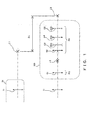
- variable power relay optical systems With reference to FIG. 1 , a configuration that is common to variable power relay optical systems according to respective examples of the present invention is described below.
- a variable power relay optical system 100 is a so-called zoom variable power optical system that is arranged closer to an image side than an imaging optical system (a master optical system 10) of a microscope apparatus, and that continuously changes magnification of an optical image projected to an imaging element of the microscope apparatus.
- the variable power relay optical system 100 is configured of a front group FG that forms an intermediate image I2 formed by reducing an image I1 of a sample to be formed by the master optical system 10, and a rear group RG that forms a relay image I3 formed by magnifying the intermediate image I2 in order from a side of the master optical system 10 (a tube lens 11).
- the front group FG is arranged between the master optical system 10 and a position of the image I1. Further, because the front group FG is configured so as to form the intermediate image I2 formed by reducing the image I1, the intermediate image I2 is formed on an object side from a position in which the image I1 is formed. This allows the variable power relay optical system 100 to suppress the extension of an optical path length, compared with a conventional variable power relay optical system that is arranged behind the image I1 so as to relay the image I1. In FIG. 1 , an optical path length extended by the variable power relay optical system 100 is expressed by ⁇ L.
- the rear group RG is configured of a plurality of lens groups that provide a zoom variable power function.
- the rear group RG includes a plurality of lens groups that each move along an optical axis so as to change a magnification of the rear group RG (and thus a magnification of the variable power relay optical system 100) without changing a distance from the front group FG to the relay image 13.
- the magnification range of the variable power relay optical system is a range of a magnification of the relay image I3 based on the image I1 (an image height of a relay image I3/an image height of an image I1), which can be changed by the variable power relay optical system.
- a high or low magnification is determined in accordance with the magnitude (an absolute value) of magnification.
- the front group FG is constituted of a first lens group G1 having positive power, as illustrated in FIG. 1 , in order to shorten an optical path length by forming the intermediate image 12 on an object side from the image I1, and it is preferable that a magnification ⁇ L1 of the first lens group G1 be smaller than 1 ⁇ .
- the magnification ⁇ L1 of the first lens group G1 is defined by "an image height of an intermediate image I2/an image height of an image I1".
- the most off-axis principal ray that is emitted from the first lens group G1 be emitted in a direction almost in parallel to the optical axis or a slightly diverging direction with respect to the optical axis (a direction apart from the optical axis). Therefore, it is preferable that the first lens group G1 include a meniscus lens with a convex surface facing a side of the master optical system 10, which is expected to have an effect to suppress convergence of the most off-axis principal ray.
- the first lens group G1 satisfy the expression below in addition to the conditions above. 0.7 ⁇ ⁇ L ⁇ 1 ⁇ 0.9
- the variable power relay optical system can obtain a wide magnification range.
- magnification ⁇ L1 exceeds an upper limit of conditional expression (1), the most off-axis principal ray is emitted from the first lens group G1 in a divergence direction, and the height of a ray being incident on the second lens group G2 becomes too great. This leads to an increase in a diameter and thickness of lenses that configure the second lens group G2 (and a third lens group G3). Many lenses are needed to greatly refract a divergent ray, and the number of lenses increases. Further, because the intermediate image I2 is close to the image I1, an effect to shorten an optical path length is also reduced.
- FIG. 2A and FIG. 2B are diagrams explaining the influence of a difference in magnification of the first lens group G1.
- FIG. 2A illustrates an example in which a most off-axis principal ray PR2 is emitted from the first lens group G1 in a direction almost in parallel to the optical axis (a principal ray PR1 on the axis).
- a magnification of the first lens group G1 illustrated in FIG. 2A is 0.71, and is near a lower limit of expression (1).
- FIG. 2B illustrates an example in which the most off-axis principal ray PR2 is emitted from the first lens group G1 in a slightly divergent direction with respect to the optical axis (the principal ray PR1 on the axis).
- FIG. 2A and FIG. 2B respectively illustrate a portion of a variable power relay optical system 1 according to Example 1 described later, and a portion of a variable power relay optical system 3 according to Example 3 described later.
- the rear group RG be configured of a second lens group G2 with positive power that is arranged at a prescribed distance from the front group FG, a third lens group G3 with negative power, which is a moving group movable along the optical axis, a fourth lens group G4 with positive power, which is a moving group movable along the optical axis, and a fifth lens group G5 with positive power, which is a moving group movable along the optical axis, in order from the front group FG.
- the moving group be configured such that a magnification range of the variable power relay optical system includes -1 ⁇ , at which a relay image I3 having the same size as that of the mage I1 is formed. Further, as illustrated in FIG. 3A to FIG. 3C , it is preferable that the moving groups move as described in (A), (B), and (C) below, while the magnitude (i.e., an absolute value) of a magnification of the variable power relay optical system is changed from a low magnification end state in which the magnitude is smallest (see FIG. 3A ) through a state of -1 ⁇ (see FIG. 3B ) to a high magnification end state in which the magnitude is greatest (see FIG. 3C ).
- the magnitude i.e., an absolute value
- the second lens group G2 have a strong positive power in order to shorten an optical path length.
- an angle of an off-axis principal ray emitted from the second lens group G2 increases. Therefore, a range of an off-axis principal ray that is incident on the third lens group G3 is changed by a slight movement of the third lens group G3, and the most off-axis principal ray that configures the relay image I3 is also changed.
- a movement distance of the third lens group G3 that is needed to realize a prescribed magnification range decreases, and therefore the optical path length of the variable power relay optical system can also decrease.
- the second lens group G2 has a function to relay the intermediate image I2 that is formed by the first lens group G1.
- the second lens group G2 In order to relay the intermediate image I2 while suppressing the generation of various aberrations relating to imaging performance, it is preferable that the second lens group G2 have a positive lens closest to the side of the master optical system 10. It is also preferable that the positive lens have a convex surface that has a stronger refractive power than a surface on the side of the master optical system 10 face the side of the relay image 13. Because an image is inverted as a result of relaying, a magnification ⁇ L2 of the second lens group G2 has a negative value.
- the second lens group G2 satisfy the expression below together with the first lens group G1 in order to obtain a high variable power ratio (a ratio of a maximum magnification to a minimum magnification of the variable power relay optical system 1) while suppressing the extension of the optical path length.
- ⁇ L1-2 expresses a comprehensive magnification of the first lens group G1 and the second lens group G2 that is defined by "an image height of a relay image formed by the first lens group G1 and the second lens group G2/an image height of an image II", and has a negative value.
- expresses the magnitude of the comprehensive magnification of the first lens group G1 and the second lens group G2.
- the magnification ⁇ L2 of the second lens group G2 is calculated by ⁇ L1-2/ ⁇ L1. 1.4 ⁇ ⁇ L ⁇ 1 - 2 ⁇ 2.2
- a magnification range of the variable power relay optical system in a magnifying direction namely, in order to enhance a magnification of the variable power relay optical system in the high magnification end state
- a large relay image be formed by using the first lens group G1 and the second lens group G2.
- of the comprehensive magnification is below a lower limit of conditional expression (2), a formed relay image is too small and the magnification of the variable power relay optical system is not sufficiently enhanced, and it is difficult to obtain a great variable power ratio.
- of the comprehensive magnification exceeds an upper limit of conditional expression (2), a position at which a relay image is formed is too far away from the second lens group, and it is difficult to sufficiently suppress the extension of the optical path length.
- the third lens group G3 greatly affects a variable power function of the variable power relay optical system, as described above.
- the third lens group G3 In order to realize a great variable power ratio while shortening a movement distance of the third lens group G3, it is preferable that the third lens group G3 have a strong negative power.
- the third lens group G3 In order to suppress the generation of various aberrations while having a strong negative power, it is preferable that the third lens group G3 include two lenses having concave surfaces facing each other.
- the fourth lens group G4 be a positive lens having a convex surface on the side of the relay image I3.
- the positive lens may be a single lens or a cemented lens.
- the positive lens may be a biconvex lens or a meniscus lens.
- the positive lens it is preferable that the positive lens have a convex surface with a stronger refractive power on the side of the relay image I3.
- the fifth lens group G5 be configured so as to form the relay image I3 at a position at which back focuses that are required by various camera mounts are secured regardless of the magnification of the variable power relay optical system and at a position that is as close as possible to the master optical system 10. It is preferable that a lens that is closest to the side of the relay image I3 in the fifth lens group G5 be a positive lens having a convex surface on the side of the master optical system 10.
- the third lens group and the lens group that follows of the variable power relay optical system may be configured by a lens group with negative power that is a moving group, and a lens group with positive power that is a moving group in order from the side of the front group FG.
- the third lens group and the lens groups that follow may be configured by a lens group with negative power that is a moving group, a lens group with positive power that is a moving group, and a fixed lens group with positive power in order from the side of the front group FG.
- an optical path length ⁇ L extended by the variable power relay optical system is about 190 mm, and the extension of the optical path length can be greatly suppressed, compared with the conventional variable power relay optical system. Accordingly, a restriction on installation is unlikely to arise.
- a distance from the intermediate image I2 to the relay image I3 is about 220 mm, and the distance can be reduced to about 1/2 of the distance of a conventional variable power relay optical system by which almost the same variable power ratio is realized (for example, in Example 2 in Japanese Laid-open Patent Publication No. 2011-150299 , 431 mm).
- a limit of a resolution of a general optical microscope is about 0.2 ⁇ m when using a high-NA 100-power oil-immersed objective lens (e.g., NA1.40), and is about 20 ⁇ m on an image plane. This corresponds to about 3 pixels when performing imaging by using, for example, an imaging element having a pixel pitch of about 6.5 ⁇ m, and therefore it is possible to barely grasp a limit of a resolution of an optical system (namely, that two points have been resolved).
- image resolution namely, the number of pixels with respect to a size of an object to be captured
- an object be further magnified with high power about 3 times or more so as to have a size of about 10 pixels.
- variable power relay optical system By adding the variable power relay optical system according to each of the examples of the present invention to an imaging apparatus, continuous variable magnification can be performed from a magnification at which the image I1 formed by the master optical system 10 is reduced to a magnification at which the image I1 is magnified with high power. Accordingly, the variable power relay optical system according to each of the examples of the present invention can be employed for a "location finding" purpose for observing a sample at a reduction magnification so as to find a specified portion in the sample, a purpose of grasping a limit of a resolution of the master optical system 10, and a purpose of magnifying an image with high power up to a magnification that exceeds the limit.
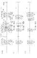
- FIG. 3A to FIG. 3C are sectional views of the variable power relay optical system 1 according to this example.
- FIG. 3A, FIG. 3B, and FIG. 3C illustrate the arrangement of lenses in a low magnification end state, in a state of -1 ⁇ , and in a high magnification end state, respectively.
- the front group FG is configured of a first lens group G1 that includes a meniscus lens (lens L1) with positive power that has a convex surface facing an object side, and a cemented lens CL1 in order from the object side (a side of the master optical system 10 not illustrated).
- the cemented lens CL1 is configured of a meniscus lens (lens L2) with positive power that has a convex surface facing the object side, and a meniscus lens (lens L3) with negative power that has a convex surface facing the object side.
- the rear group RG is configured of a second lens group G2 with positive power, a third lens group G3 with negative power, which is a moving group movable along an optical axis, a fourth lens group G4 with positive power, which is a moving group movable along the optical axis, and a fifth lens group G5 with positive power, which is movable along the optical axis, in order from the object side.
- the second lens group G2 is configured of a biconvex lens (lens L4), and a cemented lens CL2 that is configured of a biconvex lens (lens L5) and a meniscus lens (lens L6) having a concave surface facing the object side, in order from the object side.
- the second lens group G2 is a lens group that is fixed at a fixed position regardless of magnification, as illustrated in FIG. 3A to FIG. 3C .
- the third lens group G3 is configured of a biconvex lens (lens L7), and a cemented lens CL3 that is configured of a biconcave lens (lens L8) and a biconvex lens (lens L9), in order from the object side.
- the third lens group G3 moves from the side of the image I1 (intermediate image I2) to the side of the relay image I3 without reversal while the magnification is changed from the low magnification end state to the high magnification end state, as illustrated in FIG. 3A to FIG. 3C .
- the fourth lens group G4 is configured of a meniscus lens (lens L10) with positive power that has a concave surface facing the object side.
- the fourth lens group G4 moves from the side of the image I1 (intermediate image I2) to the side of the relay image I3 while the magnification is changed from the low magnification end state to the high magnification end state, and is located closer to the relay image I3 in the high magnification end state than in the low magnification end state, as illustrated in FIG. 3A to FIG. 3C .
- the fifth lens group G5 is configured of a cemented lens CL4 that is configured of a biconcave lens (lens L11) and a biconvex lens (lens L12), and a cemented lens CL5 that is configured of a biconvex lens (lens L13) and a meniscus lens (lens L14) having a concave surface facing the object side, in order from the object side.
- the fifth lens group G5 moves to the side of the image I1 (intermediate I2), and then moves to the side of the relay image 13, as illustrated in FIG. 3A to FIG. 3C .
- variable power relay optical system 1 Various kinds of data of the variable power relay optical system 1 are described below.
- a magnification ⁇ L1 of the first lens group, a comprehensive magnification ⁇ L1-2 of the first lens group and the second lens group, a maximum magnification ⁇ MAX, a minimum magnification ⁇ MIN of the variable power relay optical system 1, and an extended optical path length ⁇ L are respectively expressed below.
- the variable power relay optical system 1 satisfies expressions (1) and (2).
- ⁇ L1 0.71
- ⁇ L1-2 -1.44
- ⁇ MAX -3
- ⁇ MIN -0.63
- ⁇ L 186.428 mm
- Variable power relay optical system 1 s r d nd vd 0 INF 0.0 1.0 1 INF -55.239 1.0 2 34.160 4 1.48749 70.23 3 155.399 1 1.0 4 29.929 6 1.49700 81.54 5 179.693 2.7 1.77250 49.
- s expresses a surface number
- r expresses a radius of curvature (mm)
- d expresses a surface spacing (mm)
- nd expresses a refractive index to the d line
- vd expresses an Abbe number.
- Surface numbers s1 and s7 express image plane of the image I1 that the master optical system 10 forms
- surface number s26 expresses an image plane of the relay image I3 that the variable power relay optical system 1 forms.
- Surface spacings d12, d17, d19, and d25 are variable values D1, D2, D3, and D4, which vary in accordance with the variable power operation of the variable power relay optical system 1.
- variable values D1, D2, D3, and D4 in the low magnification end state illustrated in FIG. 3A , in the state of -1 ⁇ illustrated in FIG. 3B , and in the high magnification end state illustrated in FIG. 3C are described below.
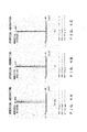
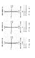
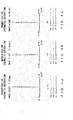
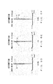
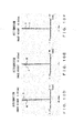
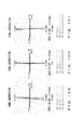
- FIG. 4A to FIG. 4L illustrate aberration of the variable power relay optical system 1.
- FIG. 4A to FIG. 4C respectively illustrate spherical aberration in the low magnification end state, in the state of -lx, and in the high magnification end state.
- FIG. 4D to FIG. 4F respectively illustrate astigmatism in the low magnification end state, in the state of -1 ⁇ , and in the high magnification end state.
- FIG. 4G to FIG. 4I respectively illustrate coma aberration in the low magnification end state, in the state of -1 ⁇ , and in the high magnification end state.
- the respective aberration diagrams illustrate an aberration amount in a case in which backward ray tracing is performed from the relay image I3 to the image I1 so as to set an entrance pupil position to the variable power relay optical system 1 to be at the infinity position.
- An image height in each of the aberration diagrams expresses an image height of the relay image I3.
- the image height is limited by a size of an imaging element, and therefore the image height is the size of the imaging element.
- M in the respective diagrams expresses a meridional component
- S expresses a sagittal component.
- FIG. 5A to FIG. 5C are sectional views of a variable power relay optical system 2 according to this example.
- FIG. 5A, FIG. 5B, and FIG. 5C illustrate the arrangement of lenses in the low magnification end state, in the state of -1 ⁇ , and in the high magnification end state, respectively.
- a front group FG is configured of a first lens group G1 that is configured of a biconvex lens (lens L1) and a cemented lens CL1, in order from an object side.
- the cemented lens CL1 is configured of a meniscus lens (lens L2) with positive power that has a convex surface facing the object side, and a meniscus lens (lens L3) with negative power that has a convex surface facing the object side.
- a rear group RG is configured of a second lens group G2 with positive power, a third lens group G3 with negative power, which is a moving group movable along an optical axis, a fourth lens group G4 with positive power, which is a moving group movable along the optical axis, and a fifth lens group G5 with positive power, which is movable along the optical axis, in order from the object side.
- the second lens group G2 is configured of a biconvex lens (lens L4), and a cemented lens CL 2 that is configured of a biconvex lens (lens L5) and a meniscus lens (lens L6) that has a concave surface facing the object side, in order from the object side.
- the third lens group G3 is configured of a biconcave lens (lens L7), and a cemented lens CL3 that is configured of a biconcave lens (lens L8) and a meniscus lens (lens L9) with positive power that has a convex surface facing the object side, in order from the object side.
- the fourth lens group G4 is configured of a meniscus lens (lens L10) with positive power that has a concave surface facing the object side.
- the fifth lens group G5 is configured of a cemented lens CL4 that is configured of a biconcave lens (lens L11) and a biconvex lens (lens L12), and a cemented lens CL5 that is configured of a biconvex lens (lens L13) and a meniscus lens (lens L14) that has a concave surface facing the object side, in order from the object side.
- the moving groups in the variable power relay optical system 2 move similarly to the moving groups in the variable power relay optical system 1 according to Example 1.
- variable power relay optical system 2 Various kinds of data of the variable power relay optical system 2 are described below.
- a magnification ⁇ L1 of the first lens group, a comprehensive magnification ⁇ L1-2 of the first lens group and the second lens group, a maximum magnification ⁇ MAX and a minimum magnification ⁇ MIN of the variable power relay optical system 2, and an extended optical path length ⁇ L are respectively expressed below.
- the variable power relay optical system 2 satisfies expressions (1) and (2).
- ⁇ L1 0.79
- ⁇ L1-2 -1.98
- ⁇ MAX -3.5
- ⁇ MIN -0.63
- ⁇ L 188.492 mm
- Variable power relay optical system 2 s r d nd vd 0 INF 0.0 1.0 1 INF -57.132 1.0 2 91.042 5.2 1.49700 81.54 3 -455.213 1 1.0 4 23.036 6.8 1.59522 67.74 5 81.428 3.8 1.77250 49.60 6 17.152 25.8 1.0 7 INF 30.921 1.0 8 78.025 5.5 1.59522 67.74 9 -24.876 0.4 1.0 10 28.342 6.5 1.43875 94.93 11 -18.521 2.5 1.80000 29.84 12 -50.476 D1 1.0 13 -23.037 1.4 1.48749 70.23 14 15.605 1.953 1.0 15 -29.071 1.4 1.51633 64.14 16 13.404 3.5 1.70154 41.24 17 98.850 D2 1.0 18 -249.961 4 1.48749 70.23 19 -27.256 D3
- FIG. 6A to FIG. 6L illustrate aberration of the variable power relay optical system 2.
- FIG. 6A to FIG. 6C respectively illustrate spherical aberration in the low magnification end state, in the state of -1 ⁇ , and in the high magnification end state.
- FIG. 6D to FIG. 6F respectively illustrate astigmatism in the low magnification end state, in the state of -1 ⁇ , and in the high magnification end state.
- FIG. 6G to FIG. 6I respectively illustrate coma aberration in the low magnification end state, in the state of -1 ⁇ , and in the high magnification end state.
- FIG. 6L respectively illustrate magnification chromatic aberration in the low magnification end state, in the state of -1 ⁇ , and in the high magnification end state. All of the aberration diagrams illustrate that the aberration has been satisfactorily corrected.
- the respective aberration diagrams are depicted in a form similar to that of the aberration diagrams of the variable power relay optical system 1 according to Example 1 illustrated in FIG. 4A to FIG. 4L .
- FIG. 7A to FIG. 7C are sectional views of a variable power relay optical system 3 according to this example.
- FIG. 7A, FIG. 7B, and FIG. 7C illustrate the arrangement of lenses in the low magnification end state, in the state of -1 ⁇ , and in the high magnification end state, respectively.
- a front group FG is configured of a first lens group G1 that is configured of a meniscus lens (lens L1) with positive power that has a convex surface facing an object side, and a cemented lens CL1, in order from the object side.
- the cemented lens CL1 is configured of a meniscus lens (lens L2) with positive power that has a convex surface facing the object side, and a meniscus lens (lens L3) with negative power that has a convex surface facing the object side.
- a rear group RG is configured of a second lens group G2 with positive power, a third lens group G3 with negative power, which is a moving group movable along an optical axis, a fourth lens group G4 with positive power, which is a moving group movable along the optical axis, and a fifth lens group with positive power, which is movable along the optical axis, in order from the object side.
- the second lens group G2 is configured of a biconvex lens (lens L4), and a cemented lens CL2 that is configured of a biconvex lens (lens L5) and a meniscus lens (lens L6) that has a concave surface facing the object side, in order from the object side.
- the third lens group G3 is configured of a biconcave lens (lens L7), and a cemented lens CL3 that is configured of a biconcave lens (lens L8) and a meniscus lens (lens L9) with positive power that has a convex surface facing the object side, in order from the object side.
- the fourth lens group G4 is configured of a meniscus lens (lens L10) with positive power that has a concave surface facing the object side.
- the fifth lens group G5 is configured of a cemented lens CL4 that is configured of a biconcave lens (lens L11) and a biconvex lens (lens L12), and a cemented lens CL5 that is configured of a biconvex lens (lens L13) and a meniscus lens (lens L14) that has a concave surface facing the object side, in order from the object side.
- the moving groups of the variable power relay optical system 3 move similarly to the moving groups of the variable power relay optical system 1 according to Example 1.
- variable power relay optical system 3 Various kinds of data of the variable power relay optical system 3 are described below.
- a magnification ⁇ L1 of the first lens group, a comprehensive magnification ⁇ L1-2 of the first lens group and the second lens group, a maximum magnification ⁇ MAX and a minimum magnification ⁇ MIN of the variable power relay optical system 3, and an extended optical path length ⁇ L are respectively expressed below.
- the variable power relay optical system 3 satisfies expressions (1) and (2).
- ⁇ L1 0.88
- ⁇ L1-2 -2.12
- ⁇ MAX -3.67
- ⁇ MIN -0.63
- ⁇ L 188.949 mm
- Variable power relay optical system 3 s r d nd vd 0 INF 0.0 1.0 1 INF -53.089 1.0 2 49.394 5.2 1.49700 81.54 3 146.650 1 1.0 4 29.100 6.8 1.59522 67.74 5 77.152 3.8 1.77250 49.60 6 19.149 27.5 1.0 7 INF 30.614 1.0 8 72.475 5.5 1.59522 67.74 9 -26.939 0.4 1.0 10 27.302 6.5 1.43875 94.93 11 -20.622 2.5 1.80000 29.84 12 -56.807 D1 1.0 13 -26.680 1.4 1.48749 70.23 14 14.814 2.199 1.0 15 -23.311 1.4 1.51633 64.14 16 14.478 3.5 1.70154 41.24 17 283.334 D2 1.0 18 -175.313 4 1.48749 70.23 19 -31.830 D3 1.0 20 -20
- FIG. 8A to FIG. 8L illustrate aberration of the variable power relay optical system 3.
- FIG. 8A to FIG. 8C respectively illustrate spherical aberration in the low magnification end state, in the state of -1 ⁇ , and in the high magnification end state.
- FIG. 8D to FIG. 8F respectively illustrate astigmatism in the low magnification end state, in the state of -1 ⁇ , and in the high magnification end state.
- FIG. 8G to FIG. 8I respectively illustrate coma aberration in the low magnification end state, in the state of -1 ⁇ , and in the high magnification end state.
- FIG. 9A to FIG. 9C are sectional views of a variable power relay optical system 4 according to this example.
- FIG. 9A, FIG. 9B, and FIG. 9C illustrate the arrangement of lenses in the low magnification end state, in the state of -1 ⁇ , and in the high magnification end state, respectively.
- a front group FG is configured of a first lens group that is configured of a meniscus lens (lens L1) with positive power that has a convex surface facing an object side, and a cemented lens CL1 in order from the object side.
- the cemented lens CL1 is configured of a meniscus lens (lens L2) with positive power that has a convex surface facing the object side, and a meniscus lens (lens L3) with negative power that has a convex surface facing the object side.
- a rear group RG is configured of a second lens group G2 with positive power, a third lens group G3 with negative power, which is a moving group movable along an optical axis, a fourth lens group G4 with positive power, which is a moving group movable along the optical axis, and a fifth lens group G5 with positive power, which is movable along the optical axis, in order from the object side.
- the second lens group G2 is a plano-convex lens (lens L4) that has a plane surface facing an object side, a biconvex lens (lens L5), and a cemented lens CL2 that is configured of a biconvex lens (lens L6) and a plano-concave lens (lens L7) that has a concave surface facing the object side, in order from the object side.
- the third lens group G3 is configured of a cemented lens CL3 that is configured of a meniscus lens (lens L8) that has a concave surface facing the object side and a biconcave lens (lens L9), and a cemented lens CL4 that is configured of a biconcave lens (lens L10) and a plano-convex lens (lens L11) that has a convex surface facing the object side, in order from the object side.
- a cemented lens CL3 that is configured of a meniscus lens (lens L8) that has a concave surface facing the object side and a biconcave lens (lens L9)
- a cemented lens CL4 that is configured of a biconcave lens (lens L10) and a plano-convex lens (lens L11) that has a convex surface facing the object side, in order from the object side.
- the fourth lens group G4 is configured of a meniscus lens (lens S12) with positive power that has a concave surface facing the object side.
- the fifth lens group G5 is configured of a cemented lens CL5 that is configured of a biconcave lens (lens L13) and a biconvex lens (lens L14), and a cemented lens CL6 that is configured of a biconvex lens (lens L15) and a meniscus lens (lens L16) that has a concave surface facing the object side, in order from the object side.
- the fourth lens group G4 moves to the side of the image I1 (intermediate image I2), and then moves to the side of the relay image I3, while the magnification is changed from the low magnification end state to the high magnification end state, as illustrated in FIG. 9A to FIG. 9C .
- the moving groups of the variable power relay optical system 4 move similarly to the moving groups of the variable power relay optical system 1 according to Example 1.
- variable power relay optical system 4 Various kinds of data of the variable power relay optical system 4 are described below.
- a magnification ⁇ L1 of the first lens group, a comprehensive magnification ⁇ L1-2 of the first lens group and the second lens group, a maximum magnification ⁇ MAX and a minimum magnification ⁇ MIN of the variable power relay optical system 4, and an extended optical path length ⁇ L are respectively expressed below.
- the variable power relay optical system 4 satisfies expressions (1) and (2).
- Variable power relay optical system 4 s r d nd vd 0 INF 0.0 1.0 1 INF -90.429 1.0 2 26.891 6.5 1.43875 94.93 3 58.102 2.5 1.0 4 28.324 10 1.60300 65.44 5 107.961 5.5 1.75500 52.32 6 13.682 34 1.0 7 INF 33 1.0 8 INF 5 1.43875 94.93 9 -33.220 0.3 1.0 10 50.273 5.5 1.43875 94.93 11 -41.888 0.5 1.0 12 31.656 7 1.43875 94.93 13 -31.656 2.5 1.73800 32.26 14 INF D1 1.0 15 -46.096 3 1.75500 52.32 16 -52.382 1.5 1.74100 52.64 17 30.155 1.532 1.0 18 -42.278 1.5 1.59522 67.74 19 20.648 3.2 1.73800 32.26 20 INF D2 1.0 21 -8
- Surface numbers s1 and s7 express image plane of the image I1 that the master optical system 10 forms
- surface number s29 expresses an image plane of the relay image 13 that the variable power relay optical system 4 forms.
- Surface spacings d14, d20, d22, and d28 are variable values D1, D2, D3, and D4, which vary in accordance with the variable power operation of the variable power relay optical system 4.
- variable values D1, D2, D3, and D4 in the low magnification end state illustrated in FIG. 9A , in the state of -1 ⁇ illustrated in FIG. 9B , and in the high magnification end state illustrated in FIG. 9C are described below.
- Magnification -0.63X -1X -3.48X D1 5.133 12.793 52.378 D2 28.580 16.330 2.183 D3 32.378 23.790 12.025 D4 63.796 76.974 63.301
- FIG. 10A to FIG. 10L illustrate aberration of the variable power relay optical system 4.
- FIG. 10A to FIG. 10C respectively illustrate spherical aberration in the low magnification end state, in the state of -1 ⁇ , and in the high magnification end state.
- FIG. 10D to FIG. 10F respectively illustrate astigmatism in the low magnification end state, in the state of -1 ⁇ , and in the high magnification end state.
- FIG. 10G to FIG. 10I respectively illustrate coma aberration in the low magnification end state, in the state of -1 ⁇ , and in the high magnification end state.
- FIG. 11A to FIG. 11C are sectional views of a variable power relay optical system 5 according to this example.
- FIG. 11A, FIG. 11B, and FIG. 11C illustrate the arrangement of lenses in the low magnification end state, in the state of -1 ⁇ , and in the high magnification end state, respectively.
- a front group FG is configured of a first lens group G1 that is configured of a cemented lens CL1 that is configured of a positive lens (lens L1) and a negative lens (lens L2) and that has a meniscus form with a concave surface facing an image side, in order from an object side.
- a cemented lens CL1 that is configured of a positive lens (lens L1) and a negative lens (lens L2) and that has a meniscus form with a concave surface facing an image side, in order from an object side.
- the front group FG is configured of a first lens group G1 that is configured of a cemented lens CL1 that includes a biconvex lens (lens L1) and a biconcave lens (lens L2), in order from the object side.
- a cemented lens CL1 that includes a biconvex lens (lens L1) and a biconcave lens (lens L2), in order from the object side.
- a rear group RG is configured of a second lens group G2 with positive power, a third lens group G3 with negative power, which is a moving group movable along an optical axis, a fourth lens group G4 with positive power, which is a moving group movable along the optical axis, and a fifth lens group G5 with positive power, in order from the object side.
- the second lens group G2 is configured of a meniscus lens (lens L3) with positive power that has a convex surface facing the side of the relay image I3, and a cemented lens that is configured of a positive lens (lens L4) and a negative lens (lens L5) and that has a biconvex shape, in order from the object side.
- the second lens group G2 is configured of a meniscus lens (lens L3) with positive power that has a concave surface facing the object side, and a cemented lens CL2 that is configured of a biconvex lens (lens L4) and a meniscus lens (lens L5) that has a concave surface facing the object side, in order from the object side.
- the second lens group G2 is a lens group that is fixed at a fixed position regardless of magnification, as illustrated in FIG. 11A to FIG. 11C .
- the third lens group G3 is configured of a negative lens (lens L6), and a cemented lens CL3 that is configured of a negative lens (lens L7) and a positive lens (lens L8) and that has a meniscus shape, in order from the object side, and has concave surfaces facing each other.
- the third lens group G3 is configured of a biconcave lens (lens L6), and a cemented lens CL3 that is configured of a biconcave lens (lens L7) and a biconvex lens (lens L8), in order from the object side.
- the third lens group G3 moves from the side of the image I1 (intermediate image I2) to the side of the relay image I3 without reversal while magnification is changed from the low magnification end state in which the magnification is lowest to the high magnification end state in which the magnification is highest, as illustrated in FIG. 11A to FIG. 11C .
- the fourth lens group G4 is configured of a cemented lens CL4 that is configured of a negative lens (lens L9) and a positive lens (lens L10), and that has a convex surface having a stronger refractive power than that of the surface on the side of the master optical system 10 on the side of the relay image I3.
- the fourth lens group G4 is configured of a cemented lens CL4 that is configured of a meniscus lens (lens L9) having a convex surface facing the object side and a biconvex lens (lens L10).
- the fourth lens group G4 moves from the side of the relay image I3 to the side of the image I1 (intermediate image I2) without reversal, while magnification is changed from the low magnification end state in which the magnification is lowest to the high magnification end state in which the magnification is highest, as illustrated in FIG. 11A to FIG. 11C .
- the fifth lens group G5 is configured of a positive lens (lens L11), and a cemented lens CL5 that is configured of a positive lens (lens L12) and a negative lens (lens L13) and that has a convex surface facing the object side, in order from the object side.
- the fifth lens group G5 is configured of a plano-convex lens (lens L11) with a convex surface facing the object side, and a cemented lens CL5 that is configured of a biconvex surface (lens L12) and a plano-concave lens (lens L13) with a concave surface facing the object side, in order from the object side.
- the fifth lens group G5 is a lens group that is fixed at a fixed position regardless of magnification, as illustrated in FIG. 11A to FIG. 11C .
- variable power relay optical system 5 Various kinds of data of the variable power relay optical system 5 are described below.
- a magnification ⁇ L1 of the first lens group, a comprehensive magnification ⁇ L1-2 of the first lens group and the second lens group, a maximum magnification ⁇ MAX and a minimum magnification ⁇ MIN of the variable power relay optical system 5, and an extended optical path length ⁇ L are respectively expressed below.
- the variable power relay optical system 5 satisfies expressions (1) and (2).
- ⁇ L1 0.70
- ⁇ L1-2 -1
- ⁇ MAX -1.25
- ⁇ MIN -0.5
- ⁇ L 222.731 mm
- Variable power relay optical system 5 s r d nd vd 0 INF 0.000 1.0 1 INF -52.832 1.0 2 34.779 5.900 1.60311 60.70 3 -99.220 4.000 1.75520 27.51 4 73.840 30.354 1.0 5 INF 53.640 1.0 6 -149.600 3.400 1.71300 53.84 7 -34.901 0.579 1.0 8 36.574 5.300 1.48749 70.21 9 -29.857 2.400 1.75520 27.51 10 -78.370 D1 1.0 11 -19.110 2.000 1.75520 27.51 12 19.110 3.362 1.0 13 -15.482 2.700 1.53172 48.91 14 27.718 4.600 1.74950 35.27 15 -16.280 D2 1.0 16 150.935 4.000 1.80518 25.43 17 69.577 5.600 1.61800 63.39 18 -94.281 D3 1.0 19 134.080 3.500
- Surface numbers s1 and s5 express image plane of the image I1 that the master optical system 10 forms
- surface number s24 expresses an image plane of the relay image I3 that the variable power relay optical system 5 forms.
- Surface spacings d10, d15, and d18 are variable values D1, D2, and D3, which vary in accordance with the variable power operation of the variable power relay optical system 5.
- variable values D1, D2, and D3 in the low magnification end state illustrated in FIG. 11A , in the state of -1 ⁇ illustrated in FIG. 11B , and in the high magnification end state illustrated in FIG. 11C are described below.
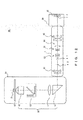
- FIG. 12 illustrates a configuration of an imaging apparatus 50 according to this example.
- the imaging apparatus 50 is a microscope apparatus that includes a microscope body 20 including the master optical system 10, the variable power relay optical system 1 according to Example 1, and a camera 30 including an imaging element 31.
- the master optical system 10 is configured so as to form the image I1 by magnifying light from a sample S arranged on a stage 15 with an objective lens 12 and a tube lens 11 that are arranged respectively on both sides across a mirror unit 13.
- a total reflection prism 14 is means for bending an optical path, and is used so as to compactly configure the entirety of the imaging apparatus 50.
- variable power relay optical system 1 is arranged on an image side of the master optical system 10 and between the microscope body 20 (the master optical system 10) and the camera 30 (the imaging element 31). Details of the variable power relay optical system 1 are omitted because they have been described above in Example 1.
- the camera 30 includes the imaging element 31 that images the relay image I3 that has been relayed by the variable power relay optical system 1.
- FIG. 12 illustrates an example in which the imaging apparatus 50 includes the variable power relay optical system 1 according to Example 1, but the imaging apparatus 50 may include a variable power relay optical system according to another example.
- the imaging apparatus 50 may be configured so as to insert as needed a variable power relay optical system between the microscope body 20 and the camera 30, as illustrated in FIG. 12 and FIG. 13 , or may have a configuration 40 in which the microscope body 20 and a variable power relay optical system are integrated, as illustrated in FIG. 14 .
- variable power relay optical system and the imaging apparatus can be made without departing from the spirit of the present invention specified in the claims.
- a single example may be realized by combining some features in the contexts of individual examples described herein.
Landscapes
- Physics & Mathematics (AREA)
- General Physics & Mathematics (AREA)
- Optics & Photonics (AREA)
- Chemical & Material Sciences (AREA)
- Analytical Chemistry (AREA)
- Lenses (AREA)
- Microscoopes, Condenser (AREA)
- Nonlinear Science (AREA)
Abstract
Description
- The present invention relates to a variable power relay optical system and an imaging apparatus that includes the variable power relay optical system.
- A variable power relay optical system is known that is arranged between an imaging optical system (hereinafter referred to as a master optical system) of an imaging apparatus such as a microscope apparatus and an imaging element, and that continuously changes magnification of an optical image projected to the imaging element. Such a variable power relay optical system is described, for example, in Japanese Laid-open Patent Publication No.
2011-150299 - A variable power relay optical system provides a function to continuously change magnification to a microscope apparatus, but extends an optical path length between a sample and an imaging element. As an example, in a variable power optical system disclosed in Japanese Laid-open Patent Publication No.
2011-150299 2011-150299 - A ratio of a length of 400 mm to the size of the microscope apparatus is never small. Therefore, when employing a conventional variable power relay optical system in a microscope apparatus, a restriction on installation is likely to arise, and various kinds of efforts are needed to install the conventional variable power relay optical system.
- In view of the above, it is an object of the present invention to provide a technique for suppressing an extension of the optical path length by a variable power optical system.
- One aspect of the present invention provides a variable power relay optical system arranged closer to an image side than an imaging optical system, the variable power relay optical system including, in order from a side of the imaging optical system, a front group that is arranged between the imaging optical system and a position of an image of a sample that is formed by the imaging optical system, the front group forming an intermediate image formed by reducing the image, and a rear group that forms a relay image formed by magnifying the intermediate image, the rear group including a plurality of lens groups that each move along an optical axis so as to change magnification of the rear group without changing a distance from the front group to the relay image.
- Another aspect of the present invention provides an imaging apparatus including the variable power relay optical system according to the aspect above, the imaging optical system, and an imaging element that images the relay image.
- According to the present invention, it is possible to provide a technique for suppressing an extension of the optical path length by a variable power optical system.
-
-
FIG. 1 is a diagram explaining a configuration of a variable power relay optical system according to an embodiment of the present invention, and an optical path length extended by the variable power relay optical system. -
FIG. 2A and FIG. 2B are diagrams explaining the influence of a difference in magnification of a first lens group, andFIG. 2A is a ray diagram in a case in which the magnification of the first lens group is low, andFIG. 2B is a ray diagram in a case in which the magnification of the first lens group is high. -
FIG. 3A to FIG. 3C are sectional views of a variable power relay optical system according to Example 1 of the present invention, andFIG. 3A, FIG. 3B, and FIG. 3C illustrate the arrangement of lenses in a low magnification end state, in a state of -1×, and in a high magnification end state, respectively. -
FIG. 4A to FIG. 4L illustrate aberration of the variable power relay optical system according to Example 1 of the present invention. -
FIG. 5A to FIG. 5C are sectional views of a variable power relay optical system according to Example 2 of the present invention, andFIG. 5A, FIG. 5B, and FIG. 5C illustrate the arrangement of lenses in a low magnification end state, in a state of -1×, and in a high magnification end state, respectively. -
FIG. 6A to FIG. 6L illustrate aberration of the variable power relay optical system according to Example 2 of the present invention. -
FIG. 7A to FIG. 7C are sectional views of a variable power relay optical system according to Example 3 of the present invention, andFIG. 7A, FIG. 7B, and FIG. 7C illustrate the arrangement of lenses in a low magnification end state, in a state of -1×, and in a high magnification end state, respectively. -
FIG. 8A to FIG. 8L illustrate aberration of the variable power relay optical system according to Example 3 of the present invention. -
FIG. 9A to FIG. 9C are sectional views of a variable power relay optical system according to Example 4 of the present invention, andFIG. 9A, FIG. 9B, and FIG. 9C illustrate the arrangement of lenses in a low magnification end state, in a state of -1×, and in a high magnification end state, respectively. -
FIG. 10A to FIG. 10L illustrate aberration of the variable power relay optical system according to Example 4 of the present invention. -
FIG. 11A to FIG. 11C are sectional views of a variable power relay optical system according to Example 5 of the present invention, andFIG. 11A, FIG. 11B, and FIG. 11C illustrate the arrangement of lenses in a low magnification end state, in a state of -1×, and in a high magnification end state, respectively. -
FIG. 12 illustrates a configuration of an imaging apparatus according to Example 6 of the present invention. -
FIG. 13 illustrates an example in which a variable power relay optical system and a master optical system are separately configured. -
FIG. 14 illustrates an example in which a variable power relay optical system and a master optical system are integrally configured. - With reference to
FIG. 1 , a configuration that is common to variable power relay optical systems according to respective examples of the present invention is described below. - A variable power relay
optical system 100 is a so-called zoom variable power optical system that is arranged closer to an image side than an imaging optical system (a master optical system 10) of a microscope apparatus, and that continuously changes magnification of an optical image projected to an imaging element of the microscope apparatus. The variable power relayoptical system 100 is configured of a front group FG that forms an intermediate image I2 formed by reducing an image I1 of a sample to be formed by the masteroptical system 10, and a rear group RG that forms a relay image I3 formed by magnifying the intermediate image I2 in order from a side of the master optical system 10 (a tube lens 11). - The front group FG is arranged between the master
optical system 10 and a position of the image I1. Further, because the front group FG is configured so as to form the intermediate image I2 formed by reducing the image I1, the intermediate image I2 is formed on an object side from a position in which the image I1 is formed. This allows the variable power relayoptical system 100 to suppress the extension of an optical path length, compared with a conventional variable power relay optical system that is arranged behind the image I1 so as to relay the image I1. InFIG. 1 , an optical path length extended by the variable power relayoptical system 100 is expressed by ΔL. - The rear group RG is configured of a plurality of lens groups that provide a zoom variable power function. The rear group RG includes a plurality of lens groups that each move along an optical axis so as to change a magnification of the rear group RG (and thus a magnification of the variable power relay optical system 100) without changing a distance from the front group FG to the
relay image 13. - With reference to
FIG. 1 to FIG. 3 , a configuration of a variable power relay optical system that is particularly desirable when suppressing the extension of an optical path length while securing a wide magnification range is described next. Here, the magnification range of the variable power relay optical system is a range of a magnification of the relay image I3 based on the image I1 (an image height of a relay image I3/an image height of an image I1), which can be changed by the variable power relay optical system. A high or low magnification is determined in accordance with the magnitude (an absolute value) of magnification. - The front group FG is constituted of a first lens group G1 having positive power, as illustrated in
FIG. 1 , in order to shorten an optical path length by forming theintermediate image 12 on an object side from the image I1, and it is preferable that a magnification βL1 of the first lens group G1 be smaller than 1×. The magnification βL1 of the first lens group G1 is defined by "an image height of an intermediate image I2/an image height of an image I1". - In order to suppress the generation of various aberrations relating to imaging performance, it is preferable that the most off-axis principal ray that is emitted from the first lens group G1 be emitted in a direction almost in parallel to the optical axis or a slightly diverging direction with respect to the optical axis (a direction apart from the optical axis). Therefore, it is preferable that the first lens group G1 include a meniscus lens with a convex surface facing a side of the master
optical system 10, which is expected to have an effect to suppress convergence of the most off-axis principal ray. - Further, in order to shorten an optical path length while suppressing the generation of various aberrations, it is preferable that the first lens group G1 satisfy the expression below in addition to the conditions above.

- When the magnification βL1 of the first lens group G1 is below a lower limit of conditional expression (1), the most off-axis principal ray is emitted from the first lens group G1 in a convergence direction, and is incident on a second lens group G2 at a low ray height. Therefore, it is difficult to satisfactorily correct aberration. As described later in detail, when the most off-axis principal ray is emitted from the second lens group G2 at a great angle, the variable power relay optical system can obtain a wide magnification range. When the most off-axis principal ray is incident on the second lens group G2 at a low ray height, it is difficult to emit the most off-axis principal ray from the second lens group G2 at a great angle, and therefore it is difficult to obtain a wide magnification range, in particular, a high magnification.
- When the magnification βL1 exceeds an upper limit of conditional expression (1), the most off-axis principal ray is emitted from the first lens group G1 in a divergence direction, and the height of a ray being incident on the second lens group G2 becomes too great. This leads to an increase in a diameter and thickness of lenses that configure the second lens group G2 (and a third lens group G3). Many lenses are needed to greatly refract a divergent ray, and the number of lenses increases. Further, because the intermediate image I2 is close to the image I1, an effect to shorten an optical path length is also reduced.
-
FIG. 2A and FIG. 2B are diagrams explaining the influence of a difference in magnification of the first lens group G1.FIG. 2A illustrates an example in which a most off-axis principal ray PR2 is emitted from the first lens group G1 in a direction almost in parallel to the optical axis (a principal ray PR1 on the axis). A magnification of the first lens group G1 illustrated inFIG. 2A is 0.71, and is near a lower limit of expression (1).FIG. 2B illustrates an example in which the most off-axis principal ray PR2 is emitted from the first lens group G1 in a slightly divergent direction with respect to the optical axis (the principal ray PR1 on the axis). A magnification of the first lens group G1 illustrated inFIG. 2B is 0.88, and is near an upper limit of expression (1).FIG. 2A and FIG. 2B respectively illustrate a portion of a variable power relayoptical system 1 according to Example 1 described later, and a portion of a variable power relayoptical system 3 according to Example 3 described later. - Comparing
FIG. 2A withFIG. 2B , as the magnification of the first lens group G1 decreases, the intermediate image I2 is formed closer to the masteroptical system 10 and the optical path length is shortened, and a tendency that a direction of the most off-axis principal ray PR2 is changed to a convergent direction can be confirmed. - It is preferable that, as illustrated in
FIG. 1 , the rear group RG be configured of a second lens group G2 with positive power that is arranged at a prescribed distance from the front group FG, a third lens group G3 with negative power, which is a moving group movable along the optical axis, a fourth lens group G4 with positive power, which is a moving group movable along the optical axis, and a fifth lens group G5 with positive power, which is a moving group movable along the optical axis, in order from the front group FG. - It is preferable that the moving group be configured such that a magnification range of the variable power relay optical system includes -1×, at which a relay image I3 having the same size as that of the mage I1 is formed. Further, as illustrated in
FIG. 3A to FIG. 3C , it is preferable that the moving groups move as described in (A), (B), and (C) below, while the magnitude (i.e., an absolute value) of a magnification of the variable power relay optical system is changed from a low magnification end state in which the magnitude is smallest (seeFIG. 3A ) through a state of -1× (seeFIG. 3B ) to a high magnification end state in which the magnitude is greatest (seeFIG. 3C ). - (A) The third lens group G3 moves from a side of the intermediate image 12 (image I1) to a side of the relay image I3 without reversal.
- (B) The fourth lens group G4 moves from the side of the intermediate image I2 (image I1) to the side of the relay image I3. The fourth lens group G4 is located closer to the side of the relay image I3 in the high magnification end state than in the low magnification end state.
- (C) The fifth lens group G5 moves to the side of the relay image I3 after moving to the side of the intermediate image 12 (namely, the side of the image I1).
- It is preferable that the second lens group G2 have a strong positive power in order to shorten an optical path length. When the second lens power G2 has a strong positive power, an angle of an off-axis principal ray emitted from the second lens group G2 increases. Therefore, a range of an off-axis principal ray that is incident on the third lens group G3 is changed by a slight movement of the third lens group G3, and the most off-axis principal ray that configures the relay image I3 is also changed. As a result, a movement distance of the third lens group G3 that is needed to realize a prescribed magnification range decreases, and therefore the optical path length of the variable power relay optical system can also decrease.
- The second lens group G2 has a function to relay the intermediate image I2 that is formed by the first lens group G1. In order to relay the intermediate image I2 while suppressing the generation of various aberrations relating to imaging performance, it is preferable that the second lens group G2 have a positive lens closest to the side of the master
optical system 10. It is also preferable that the positive lens have a convex surface that has a stronger refractive power than a surface on the side of the masteroptical system 10 face the side of therelay image 13. Because an image is inverted as a result of relaying, a magnification βL2 of the second lens group G2 has a negative value. - Further, it is preferable that the second lens group G2 satisfy the expression below together with the first lens group G1 in order to obtain a high variable power ratio (a ratio of a maximum magnification to a minimum magnification of the variable power relay optical system 1) while suppressing the extension of the optical path length. βL1-2 expresses a comprehensive magnification of the first lens group G1 and the second lens group G2 that is defined by "an image height of a relay image formed by the first lens group G1 and the second lens group G2/an image height of an image II", and has a negative value. |βL1-2| expresses the magnitude of the comprehensive magnification of the first lens group G1 and the second lens group G2. The magnification βL2 of the second lens group G2 is calculated by βL1-2/βL1.

- In order to widen a magnification range of the variable power relay optical system in a magnifying direction (namely, in order to enhance a magnification of the variable power relay optical system in the high magnification end state), it is preferable that a large relay image be formed by using the first lens group G1 and the second lens group G2. When the magnitude |βL1-2| of the comprehensive magnification is below a lower limit of conditional expression (2), a formed relay image is too small and the magnification of the variable power relay optical system is not sufficiently enhanced, and it is difficult to obtain a great variable power ratio. When the magnitude |βL1-2| of the comprehensive magnification exceeds an upper limit of conditional expression (2), a position at which a relay image is formed is too far away from the second lens group, and it is difficult to sufficiently suppress the extension of the optical path length.
- The third lens group G3 greatly affects a variable power function of the variable power relay optical system, as described above. In order to realize a great variable power ratio while shortening a movement distance of the third lens group G3, it is preferable that the third lens group G3 have a strong negative power. In order to suppress the generation of various aberrations while having a strong negative power, it is preferable that the third lens group G3 include two lenses having concave surfaces facing each other.
- It is preferable that the fourth lens group G4 be a positive lens having a convex surface on the side of the relay image I3. The positive lens may be a single lens or a cemented lens. The positive lens may be a biconvex lens or a meniscus lens. When the positive lens is a biconvex lens, it is preferable that the positive lens have a convex surface with a stronger refractive power on the side of the relay image I3.
- It is preferable that the fifth lens group G5 be configured so as to form the relay image I3 at a position at which back focuses that are required by various camera mounts are secured regardless of the magnification of the variable power relay optical system and at a position that is as close as possible to the master
optical system 10. It is preferable that a lens that is closest to the side of the relay image I3 in the fifth lens group G5 be a positive lens having a convex surface on the side of the masteroptical system 10. - When a request for the suppression of the extension of an optical path length or a request for a high variable power ratio is relatively less strict, the third lens group and the lens group that follows of the variable power relay optical system may be configured by a lens group with negative power that is a moving group, and a lens group with positive power that is a moving group in order from the side of the front group FG. The third lens group and the lens groups that follow may be configured by a lens group with negative power that is a moving group, a lens group with positive power that is a moving group, and a fixed lens group with positive power in order from the side of the front group FG.
- According to a variable power relay optical system according to each of the examples of the present invention, an optical path length ΔL extended by the variable power relay optical system is about 190 mm, and the extension of the optical path length can be greatly suppressed, compared with the conventional variable power relay optical system. Accordingly, a restriction on installation is unlikely to arise. A distance from the intermediate image I2 to the relay image I3 is about 220 mm, and the distance can be reduced to about 1/2 of the distance of a conventional variable power relay optical system by which almost the same variable power ratio is realized (for example, in Example 2 in Japanese Laid-open Patent Publication No.
2011-150299 - A limit of a resolution of a general optical microscope is about 0.2 µm when using a high-NA 100-power oil-immersed objective lens (e.g., NA1.40), and is about 20 µm on an image plane. This corresponds to about 3 pixels when performing imaging by using, for example, an imaging element having a pixel pitch of about 6.5 µm, and therefore it is possible to barely grasp a limit of a resolution of an optical system (namely, that two points have been resolved). However, image resolution (namely, the number of pixels with respect to a size of an object to be captured) is insufficient to grasp a limit of a two-point resolution on an observed image. In the condition above, in order to have an observed image obtain a sufficient resolution, it is preferable that an object be further magnified with high power about 3 times or more so as to have a size of about 10 pixels.
- By adding the variable power relay optical system according to each of the examples of the present invention to an imaging apparatus, continuous variable magnification can be performed from a magnification at which the image I1 formed by the master
optical system 10 is reduced to a magnification at which the image I1 is magnified with high power. Accordingly, the variable power relay optical system according to each of the examples of the present invention can be employed for a "location finding" purpose for observing a sample at a reduction magnification so as to find a specified portion in the sample, a purpose of grasping a limit of a resolution of the masteroptical system 10, and a purpose of magnifying an image with high power up to a magnification that exceeds the limit. - Respective examples are specifically described below. Description of the configuration above that is common to the variable power relay optical systems according to the respective examples is omitted.
-
FIG. 3A to FIG. 3C are sectional views of the variable power relayoptical system 1 according to this example.FIG. 3A, FIG. 3B, and FIG. 3C illustrate the arrangement of lenses in a low magnification end state, in a state of -1×, and in a high magnification end state, respectively. - The front group FG is configured of a first lens group G1 that includes a meniscus lens (lens L1) with positive power that has a convex surface facing an object side, and a cemented lens CL1 in order from the object side (a side of the master
optical system 10 not illustrated). The cemented lens CL1 is configured of a meniscus lens (lens L2) with positive power that has a convex surface facing the object side, and a meniscus lens (lens L3) with negative power that has a convex surface facing the object side. - The rear group RG is configured of a second lens group G2 with positive power, a third lens group G3 with negative power, which is a moving group movable along an optical axis, a fourth lens group G4 with positive power, which is a moving group movable along the optical axis, and a fifth lens group G5 with positive power, which is movable along the optical axis, in order from the object side.
- The second lens group G2 is configured of a biconvex lens (lens L4), and a cemented lens CL2 that is configured of a biconvex lens (lens L5) and a meniscus lens (lens L6) having a concave surface facing the object side, in order from the object side. The second lens group G2 is a lens group that is fixed at a fixed position regardless of magnification, as illustrated in
FIG. 3A to FIG. 3C . - The third lens group G3 is configured of a biconvex lens (lens L7), and a cemented lens CL3 that is configured of a biconcave lens (lens L8) and a biconvex lens (lens L9), in order from the object side. The third lens group G3 moves from the side of the image I1 (intermediate image I2) to the side of the relay image I3 without reversal while the magnification is changed from the low magnification end state to the high magnification end state, as illustrated in
FIG. 3A to FIG. 3C . - The fourth lens group G4 is configured of a meniscus lens (lens L10) with positive power that has a concave surface facing the object side. The fourth lens group G4 moves from the side of the image I1 (intermediate image I2) to the side of the relay image I3 while the magnification is changed from the low magnification end state to the high magnification end state, and is located closer to the relay image I3 in the high magnification end state than in the low magnification end state, as illustrated in
FIG. 3A to FIG. 3C . - The fifth lens group G5 is configured of a cemented lens CL4 that is configured of a biconcave lens (lens L11) and a biconvex lens (lens L12), and a cemented lens CL5 that is configured of a biconvex lens (lens L13) and a meniscus lens (lens L14) having a concave surface facing the object side, in order from the object side. The fifth lens group G5 moves to the side of the image I1 (intermediate I2), and then moves to the side of the
relay image 13, as illustrated inFIG. 3A to FIG. 3C . - Various kinds of data of the variable power relay
optical system 1 are described below. - A magnification βL1 of the first lens group, a comprehensive magnification βL1-2 of the first lens group and the second lens group, a maximum magnification βMAX, a minimum magnification βMIN of the variable power relay
optical system 1, and an extended optical path length ΔL are respectively expressed below. The variable power relayoptical system 1 satisfies expressions (1) and (2).
β L1 = 0.71, βL1-2 = -1.44,
β MAX = -3, βMIN = -0.63,
Δ L = 186.428 mm - Lens data of the variable power relay
optical system 1 is described below.Variable power relay optical system 1 s r d nd vd 0 INF 0.0 1.0 1 INF -55.239 1.0 2 34.160 4 1.48749 70.23 3 155.399 1 1.0 4 29.929 6 1.49700 81.54 5 179.693 2.7 1.77250 49. 60 6 25.036 25.0 1.0 7 INF 32.131 1.0 8 63.954 3.5 1.59522 67.74 9 -25.864 0.4 1.0 10 34.500 4.5 1.49700 81.54 11 -18.473 2 1.80000 29.84 12 -56.514 D1 1.0 13 -22.204 1 1.74951 35.33 14 12.838 2.027 1.0 15 -19.569 1.5 1.43875 94.93 16 16.442 4 1.80000 29.84 17 -92.068 D2 1.0 18 -59.914 3.5 1.59522 67.74 19 -20.465 D3 1.0 20 -227.079 3 1.80810 22.76 21 146.561 7 1.49700 81.54 22 -42.085 1 1.0 23 39.276 9 1.49700 81.54 24 -36.813 3 1.75500 52.32 25 -138.615 D4 1.0 26 INF 0 1.0 - Here, s expresses a surface number, r expresses a radius of curvature (mm), d expresses a surface spacing (mm), nd expresses a refractive index to the d line, and vd expresses an Abbe number. Surface numbers s1 and s7 express image plane of the image I1 that the master
optical system 10 forms, and surface number s26 expresses an image plane of the relay image I3 that the variable power relayoptical system 1 forms. Surface spacings d12, d17, d19, and d25 are variable values D1, D2, D3, and D4, which vary in accordance with the variable power operation of the variable power relayoptical system 1. - The variable values D1, D2, D3, and D4 in the low magnification end state illustrated in
FIG. 3A , in the state of -1× illustrated inFIG. 3B , and in the high magnification end state illustrated inFIG. 3C are described below.Magnification -0.63X -1X -3X D1 3.415 14.801 42.985 D2 10.173 8.351 1.337 D3 36.440 19.189 14.739 D4 75.381 83.068 66.348 -
FIG. 4A to FIG. 4L illustrate aberration of the variable power relayoptical system 1.FIG. 4A to FIG. 4C respectively illustrate spherical aberration in the low magnification end state, in the state of -lx, and in the high magnification end state.FIG. 4D to FIG. 4F respectively illustrate astigmatism in the low magnification end state, in the state of -1×, and in the high magnification end state.FIG. 4G to FIG. 4I respectively illustrate coma aberration in the low magnification end state, in the state of -1×, and in the high magnification end state.FIG. 4J to FIG. 4L respectively illustrate magnification chromatic aberration in the low magnification end state, in the state of -1×, and in the high magnification end state. All of the aberration diagrams illustrate that the aberration has been satisfactorily corrected. In order to compare the extent of aberration in the same-scale regardless of magnification, the respective aberration diagrams illustrate an aberration amount in a case in which backward ray tracing is performed from the relay image I3 to the image I1 so as to set an entrance pupil position to the variable power relayoptical system 1 to be at the infinity position. An image height in each of the aberration diagrams expresses an image height of the relay image I3. In the state of -1× and in the high magnification end state, the image height is limited by a size of an imaging element, and therefore the image height is the size of the imaging element. "M" in the respective diagrams expresses a meridional component, and "S" expresses a sagittal component. -
FIG. 5A to FIG. 5C are sectional views of a variable power relayoptical system 2 according to this example.FIG. 5A, FIG. 5B, and FIG. 5C illustrate the arrangement of lenses in the low magnification end state, in the state of -1×, and in the high magnification end state, respectively. - A front group FG is configured of a first lens group G1 that is configured of a biconvex lens (lens L1) and a cemented lens CL1, in order from an object side. The cemented lens CL1 is configured of a meniscus lens (lens L2) with positive power that has a convex surface facing the object side, and a meniscus lens (lens L3) with negative power that has a convex surface facing the object side.
- A rear group RG is configured of a second lens group G2 with positive power, a third lens group G3 with negative power, which is a moving group movable along an optical axis, a fourth lens group G4 with positive power, which is a moving group movable along the optical axis, and a fifth lens group G5 with positive power, which is movable along the optical axis, in order from the object side.
- The second lens group G2 is configured of a biconvex lens (lens L4), and a cemented
lens CL 2 that is configured of a biconvex lens (lens L5) and a meniscus lens (lens L6) that has a concave surface facing the object side, in order from the object side. - The third lens group G3 is configured of a biconcave lens (lens L7), and a cemented lens CL3 that is configured of a biconcave lens (lens L8) and a meniscus lens (lens L9) with positive power that has a convex surface facing the object side, in order from the object side.
- The fourth lens group G4 is configured of a meniscus lens (lens L10) with positive power that has a concave surface facing the object side.
- The fifth lens group G5 is configured of a cemented lens CL4 that is configured of a biconcave lens (lens L11) and a biconvex lens (lens L12), and a cemented lens CL5 that is configured of a biconvex lens (lens L13) and a meniscus lens (lens L14) that has a concave surface facing the object side, in order from the object side.
- The moving groups in the variable power relay
optical system 2 move similarly to the moving groups in the variable power relayoptical system 1 according to Example 1. - Various kinds of data of the variable power relay
optical system 2 are described below. - A magnification βL1 of the first lens group, a comprehensive magnification βL1-2 of the first lens group and the second lens group, a maximum magnification βMAX and a minimum magnification βMIN of the variable power relay
optical system 2, and an extended optical path length ΔL are respectively expressed below. The variable power relayoptical system 2 satisfies expressions (1) and (2).
β L1 = 0.79, βL1-2 = -1.98,
β MAX = -3.5, βMIN = -0.63,
Δ L = 188.492 mm - Lens data of the variable power relay
optical system 2 is described below.Variable power relay optical system 2 s r d nd vd 0 INF 0.0 1.0 1 INF -57.132 1.0 2 91.042 5.2 1.49700 81.54 3 -455.213 1 1.0 4 23.036 6.8 1.59522 67.74 5 81.428 3.8 1.77250 49.60 6 17.152 25.8 1.0 7 INF 30.921 1.0 8 78.025 5.5 1.59522 67.74 9 -24.876 0.4 1.0 10 28.342 6.5 1.43875 94.93 11 -18.521 2.5 1.80000 29.84 12 -50.476 D1 1.0 13 -23.037 1.4 1.48749 70.23 14 15.605 1.953 1.0 15 -29.071 1.4 1.51633 64.14 16 13.404 3.5 1.70154 41.24 17 98.850 D2 1.0 18 -249.961 4 1.48749 70.23 19 -27.256 D3 1.0 20 -113.791 3 1.80810 22.76 21 294.811 6 1.59522 67.74 22 -49.109 1 1.0 23 48.065 9 1.59522 67.74 24 -29.158 3 1.75500 52.32 25 -89.031 D4 1.0 26 INF 0 1.0 - Variable values D1, D2, D3, and D4 in the low magnification end state illustrated in
FIG. 5A , in the state of -1× illustrated inFIG. 5B , and in the high magnification end state illustrated inFIG. 5C are described below.Magnification -0.63X -1X -3.5X D1 3.403 12.115 48.585 D2 15.855 10.392 2.760 D3 38.414 23.143 9.241 D4 63.278 75.300 60.363 -
FIG. 6A to FIG. 6L illustrate aberration of the variable power relayoptical system 2.FIG. 6A to FIG. 6C respectively illustrate spherical aberration in the low magnification end state, in the state of -1×, and in the high magnification end state.FIG. 6D to FIG. 6F respectively illustrate astigmatism in the low magnification end state, in the state of -1×, and in the high magnification end state.FIG. 6G to FIG. 6I respectively illustrate coma aberration in the low magnification end state, in the state of -1×, and in the high magnification end state.FIG. 6J to FIG. 6L respectively illustrate magnification chromatic aberration in the low magnification end state, in the state of -1×, and in the high magnification end state. All of the aberration diagrams illustrate that the aberration has been satisfactorily corrected. The respective aberration diagrams are depicted in a form similar to that of the aberration diagrams of the variable power relayoptical system 1 according to Example 1 illustrated inFIG. 4A to FIG. 4L . -
FIG. 7A to FIG. 7C are sectional views of a variable power relayoptical system 3 according to this example.FIG. 7A, FIG. 7B, and FIG. 7C illustrate the arrangement of lenses in the low magnification end state, in the state of -1×, and in the high magnification end state, respectively. - A front group FG is configured of a first lens group G1 that is configured of a meniscus lens (lens L1) with positive power that has a convex surface facing an object side, and a cemented lens CL1, in order from the objet side. The cemented lens CL1 is configured of a meniscus lens (lens L2) with positive power that has a convex surface facing the object side, and a meniscus lens (lens L3) with negative power that has a convex surface facing the object side.
- A rear group RG is configured of a second lens group G2 with positive power, a third lens group G3 with negative power, which is a moving group movable along an optical axis, a fourth lens group G4 with positive power, which is a moving group movable along the optical axis, and a fifth lens group with positive power, which is movable along the optical axis, in order from the object side.
- The second lens group G2 is configured of a biconvex lens (lens L4), and a cemented lens CL2 that is configured of a biconvex lens (lens L5) and a meniscus lens (lens L6) that has a concave surface facing the object side, in order from the object side.
- The third lens group G3 is configured of a biconcave lens (lens L7), and a cemented lens CL3 that is configured of a biconcave lens (lens L8) and a meniscus lens (lens L9) with positive power that has a convex surface facing the object side, in order from the object side.
- The fourth lens group G4 is configured of a meniscus lens (lens L10) with positive power that has a concave surface facing the object side.
- The fifth lens group G5 is configured of a cemented lens CL4 that is configured of a biconcave lens (lens L11) and a biconvex lens (lens L12), and a cemented lens CL5 that is configured of a biconvex lens (lens L13) and a meniscus lens (lens L14) that has a concave surface facing the object side, in order from the object side.
- The moving groups of the variable power relay
optical system 3 move similarly to the moving groups of the variable power relayoptical system 1 according to Example 1. - Various kinds of data of the variable power relay
optical system 3 are described below. - A magnification βL1 of the first lens group, a comprehensive magnification βL1-2 of the first lens group and the second lens group, a maximum magnification βMAX and a minimum magnification βMIN of the variable power relay
optical system 3, and an extended optical path length ΔL are respectively expressed below. The variable power relayoptical system 3 satisfies expressions (1) and (2).
β L1 = 0.88, βL1-2 = -2.12,
β MAX = -3.67, βMIN = -0.63,
Δ L = 188.949 mm - Lens data of the variable power relay
optical system 3 is described below.Variable power relay optical system 3 s r d nd vd 0 INF 0.0 1.0 1 INF -53.089 1.0 2 49.394 5.2 1.49700 81.54 3 146.650 1 1.0 4 29.100 6.8 1.59522 67.74 5 77.152 3.8 1.77250 49.60 6 19.149 27.5 1.0 7 INF 30.614 1.0 8 72.475 5.5 1.59522 67.74 9 -26.939 0.4 1.0 10 27.302 6.5 1.43875 94.93 11 -20.622 2.5 1.80000 29.84 12 -56.807 D1 1.0 13 -26.680 1.4 1.48749 70.23 14 14.814 2.199 1.0 15 -23.311 1.4 1.51633 64.14 16 14.478 3.5 1.70154 41.24 17 283.334 D2 1.0 18 -175.313 4 1.48749 70.23 19 -31.830 D3 1.0 20 -204.038 3 1.80810 22.76 21 140.417 6 1.59522 67.74 22 -50.094 1 1.0 23 45.693 9 1.59522 67.74 24 -29.087 3 1.75500 52.32 25 -94.315 D4 1.0 26 INF 0 1.0 - Variable values D1, D2, D3, and D4 in the low magnification end state illustrated in
FIG. 7A , in the state of -1× illustrated inFIG. 7B , and in the high magnification end state illustrated inFIG. 7C are described below.Magnification -0.63X -1X -3.67X D1 4.0804 12.124 48.319 D2 15.4490 10.318 3.114 D3 37.1624 23.270 8.638 D4 61.0335 72.014 57.654 -
FIG. 8A to FIG. 8L illustrate aberration of the variable power relayoptical system 3.FIG. 8A to FIG. 8C respectively illustrate spherical aberration in the low magnification end state, in the state of -1×, and in the high magnification end state.FIG. 8D to FIG. 8F respectively illustrate astigmatism in the low magnification end state, in the state of -1×, and in the high magnification end state.FIG. 8G to FIG. 8I respectively illustrate coma aberration in the low magnification end state, in the state of -1×, and in the high magnification end state.FIG. 8J to FIG. 8L respectively illustrate magnification chromatic aberration in the low magnification end state, in the state of -1×, and in the high magnification end state. All of the aberration diagrams illustrate that the aberration has been satisfactorily corrected. The respective aberration diagrams are depicted in a form similar to that of the aberration diagrams of the variable power relayoptical system 1 according to Example 1 illustrated inFIG. 4A to FIG. 4L . -
FIG. 9A to FIG. 9C are sectional views of a variable power relayoptical system 4 according to this example.FIG. 9A, FIG. 9B, and FIG. 9C illustrate the arrangement of lenses in the low magnification end state, in the state of -1×, and in the high magnification end state, respectively. - A front group FG is configured of a first lens group that is configured of a meniscus lens (lens L1) with positive power that has a convex surface facing an object side, and a cemented lens CL1 in order from the object side. The cemented lens CL1 is configured of a meniscus lens (lens L2) with positive power that has a convex surface facing the object side, and a meniscus lens (lens L3) with negative power that has a convex surface facing the object side.
- A rear group RG is configured of a second lens group G2 with positive power, a third lens group G3 with negative power, which is a moving group movable along an optical axis, a fourth lens group G4 with positive power, which is a moving group movable along the optical axis, and a fifth lens group G5 with positive power, which is movable along the optical axis, in order from the object side.
- The second lens group G2 is a plano-convex lens (lens L4) that has a plane surface facing an object side, a biconvex lens (lens L5), and a cemented lens CL2 that is configured of a biconvex lens (lens L6) and a plano-concave lens (lens L7) that has a concave surface facing the object side, in order from the object side.
- The third lens group G3 is configured of a cemented lens CL3 that is configured of a meniscus lens (lens L8) that has a concave surface facing the object side and a biconcave lens (lens L9), and a cemented lens CL4 that is configured of a biconcave lens (lens L10) and a plano-convex lens (lens L11) that has a convex surface facing the object side, in order from the object side.
- The fourth lens group G4 is configured of a meniscus lens (lens S12) with positive power that has a concave surface facing the object side.
- The fifth lens group G5 is configured of a cemented lens CL5 that is configured of a biconcave lens (lens L13) and a biconvex lens (lens L14), and a cemented lens CL6 that is configured of a biconvex lens (lens L15) and a meniscus lens (lens L16) that has a concave surface facing the object side, in order from the object side.
- The fourth lens group G4 moves to the side of the image I1 (intermediate image I2), and then moves to the side of the relay image I3, while the magnification is changed from the low magnification end state to the high magnification end state, as illustrated in
FIG. 9A to FIG. 9C . In the other points, the moving groups of the variable power relayoptical system 4 move similarly to the moving groups of the variable power relayoptical system 1 according to Example 1. - Various kinds of data of the variable power relay
optical system 4 are described below. - A magnification βL1 of the first lens group, a comprehensive magnification βL1-2 of the first lens group and the second lens group, a maximum magnification βMAX and a minimum magnification βMIN of the variable power relay
optical system 4, and an extended optical path length ΔL are respectively expressed below. The variable power relayoptical system 4 satisfies expressions (1) and (2).
β L1 = 0.81, βL1-2 = -2.10,
β MAX = -3.48, βMIN = -0.63,
Δ L = 187.99 mm - Lens data of the variable power relay
optical system 4 is expressed below.Variable power relay optical system 4 s r d nd vd 0 INF 0.0 1.0 1 INF -90.429 1.0 2 26.891 6.5 1.43875 94.93 3 58.102 2.5 1.0 4 28.324 10 1.60300 65.44 5 107.961 5.5 1.75500 52.32 6 13.682 34 1.0 7 INF 33 1.0 8 INF 5 1.43875 94.93 9 -33.220 0.3 1.0 10 50.273 5.5 1.43875 94.93 11 -41.888 0.5 1.0 12 31.656 7 1.43875 94.93 13 -31.656 2.5 1.73800 32.26 14 INF D1 1.0 15 -46.096 3 1.75500 52.32 16 -52.382 1.5 1.74100 52.64 17 30.155 1.532 1.0 18 -42.278 1.5 1.59522 67.74 19 20.648 3.2 1.73800 32.26 20 INF D2 1.0 21 -8115.610 3.5 1.43875 94.93 22 -44.483 D3 1.0 23 -164.406 2.8 1.73800 32.26 24 55.860 6 1.60300 65.44 25 -55.860 1 1.0 26 48.806 9 1.60300 65.44 27 -31.390 3.2 1.75500 52.32 28 -98.616 D4 1.0 29 INF 0 1.0 - Surface numbers s1 and s7 express image plane of the image I1 that the master
optical system 10 forms, and surface number s29 expresses an image plane of therelay image 13 that the variable power relayoptical system 4 forms. Surface spacings d14, d20, d22, and d28 are variable values D1, D2, D3, and D4, which vary in accordance with the variable power operation of the variable power relayoptical system 4. - The variable values D1, D2, D3, and D4 in the low magnification end state illustrated in
FIG. 9A , in the state of -1× illustrated inFIG. 9B , and in the high magnification end state illustrated inFIG. 9C are described below.Magnification -0.63X -1X -3.48X D1 5.133 12.793 52.378 D2 28.580 16.330 2.183 D3 32.378 23.790 12.025 D4 63.796 76.974 63.301 -
FIG. 10A to FIG. 10L illustrate aberration of the variable power relayoptical system 4.FIG. 10A to FIG. 10C respectively illustrate spherical aberration in the low magnification end state, in the state of -1×, and in the high magnification end state.FIG. 10D to FIG. 10F respectively illustrate astigmatism in the low magnification end state, in the state of -1×, and in the high magnification end state.FIG. 10G to FIG. 10I respectively illustrate coma aberration in the low magnification end state, in the state of -1×, and in the high magnification end state.FIG. 10J to FIG. 10L respectively illustrate magnification chromatic aberration in the low magnification end state, in the state of -1×, and in the high magnification end state. All of the aberration diagrams illustrate that the aberration has been satisfactorily corrected. The respective aberration diagrams are depicted in a form similar to that of the aberration diagrams of the variable power relayoptical system 1 according to Example 1 illustrated inFIG. 4A to FIG. 4L . -
FIG. 11A to FIG. 11C are sectional views of a variable power relayoptical system 5 according to this example.FIG. 11A, FIG. 11B, and FIG. 11C illustrate the arrangement of lenses in the low magnification end state, in the state of -1×, and in the high magnification end state, respectively. - A front group FG is configured of a first lens group G1 that is configured of a cemented lens CL1 that is configured of a positive lens (lens L1) and a negative lens (lens L2) and that has a meniscus form with a concave surface facing an image side, in order from an object side.
- In particular, the front group FG is configured of a first lens group G1 that is configured of a cemented lens CL1 that includes a biconvex lens (lens L1) and a biconcave lens (lens L2), in order from the object side.
- A rear group RG is configured of a second lens group G2 with positive power, a third lens group G3 with negative power, which is a moving group movable along an optical axis, a fourth lens group G4 with positive power, which is a moving group movable along the optical axis, and a fifth lens group G5 with positive power, in order from the object side.
- The second lens group G2 is configured of a meniscus lens (lens L3) with positive power that has a convex surface facing the side of the relay image I3, and a cemented lens that is configured of a positive lens (lens L4) and a negative lens (lens L5) and that has a biconvex shape, in order from the object side.
- In particular, the second lens group G2 is configured of a meniscus lens (lens L3) with positive power that has a concave surface facing the object side, and a cemented lens CL2 that is configured of a biconvex lens (lens L4) and a meniscus lens (lens L5) that has a concave surface facing the object side, in order from the object side. The second lens group G2 is a lens group that is fixed at a fixed position regardless of magnification, as illustrated in
FIG. 11A to FIG. 11C . - The third lens group G3 is configured of a negative lens (lens L6), and a cemented lens CL3 that is configured of a negative lens (lens L7) and a positive lens (lens L8) and that has a meniscus shape, in order from the object side, and has concave surfaces facing each other.
- In particular, the third lens group G3 is configured of a biconcave lens (lens L6), and a cemented lens CL3 that is configured of a biconcave lens (lens L7) and a biconvex lens (lens L8), in order from the object side. The third lens group G3 moves from the side of the image I1 (intermediate image I2) to the side of the relay image I3 without reversal while magnification is changed from the low magnification end state in which the magnification is lowest to the high magnification end state in which the magnification is highest, as illustrated in
FIG. 11A to FIG. 11C . - The fourth lens group G4 is configured of a cemented lens CL4 that is configured of a negative lens (lens L9) and a positive lens (lens L10), and that has a convex surface having a stronger refractive power than that of the surface on the side of the master
optical system 10 on the side of the relay image I3. - In particular, the fourth lens group G4 is configured of a cemented lens CL4 that is configured of a meniscus lens (lens L9) having a convex surface facing the object side and a biconvex lens (lens L10). The fourth lens group G4 moves from the side of the relay image I3 to the side of the image I1 (intermediate image I2) without reversal, while magnification is changed from the low magnification end state in which the magnification is lowest to the high magnification end state in which the magnification is highest, as illustrated in
FIG. 11A to FIG. 11C . - The fifth lens group G5 is configured of a positive lens (lens L11), and a cemented lens CL5 that is configured of a positive lens (lens L12) and a negative lens (lens L13) and that has a convex surface facing the object side, in order from the object side.
- In particular, the fifth lens group G5 is configured of a plano-convex lens (lens L11) with a convex surface facing the object side, and a cemented lens CL5 that is configured of a biconvex surface (lens L12) and a plano-concave lens (lens L13) with a concave surface facing the object side, in order from the object side. The fifth lens group G5 is a lens group that is fixed at a fixed position regardless of magnification, as illustrated in
FIG. 11A to FIG. 11C . - Various kinds of data of the variable power relay
optical system 5 are described below. - A magnification βL1 of the first lens group, a comprehensive magnification βL1-2 of the first lens group and the second lens group, a maximum magnification βMAX and a minimum magnification βMIN of the variable power relay
optical system 5, and an extended optical path length ΔL are respectively expressed below. The variable power relayoptical system 5 satisfies expressions (1) and (2).
β L1 = 0.70, βL1-2 = -1,
β MAX = -1.25, βMIN = -0.5,
Δ L = 222.731 mm - Lens data of the variable power relay
optical system 5 is described below.Variable power relay optical system 5 s r d nd vd 0 INF 0.000 1.0 1 INF -52.832 1.0 2 34.779 5.900 1.60311 60.70 3 -99.220 4.000 1.75520 27.51 4 73.840 30.354 1.0 5 INF 53.640 1.0 6 -149.600 3.400 1.71300 53.84 7 -34.901 0.579 1.0 8 36.574 5.300 1.48749 70.21 9 -29.857 2.400 1.75520 27.51 10 -78.370 D1 1.0 11 -19.110 2.000 1.75520 27.51 12 19.110 3.362 1.0 13 -15.482 2.700 1.53172 48.91 14 27.718 4.600 1.74950 35.27 15 -16.280 D2 1.0 16 150.935 4.000 1.80518 25.43 17 69.577 5.600 1.61800 63.39 18 -94.281 D3 1.0 19 134.080 3.500 1.48749 70.21 20 INF 0.500 1.0 21 54.286 5.700 1.48749 70.21 22 -139.516 3.300 1.75520 27.51 23 INF 70.114 1.0 24 INF 0 1.0 - Surface numbers s1 and s5 express image plane of the image I1 that the master
optical system 10 forms, and surface number s24 expresses an image plane of the relay image I3 that the variable power relayoptical system 5 forms. Surface spacings d10, d15, and d18 are variable values D1, D2, and D3, which vary in accordance with the variable power operation of the variable power relayoptical system 5. - The variable values D1, D2, and D3 in the low magnification end state illustrated in
FIG. 11A , in the state of -1× illustrated inFIG. 11B , and in the high magnification end state illustrated inFIG. 11C are described below.Magnification -0.5X -1X -1.25X D1 16.659 34.385 37.752 D2 46.728 16.115 2.085 D3 1.228 14.115 24.777 -
FIG. 12 illustrates a configuration of animaging apparatus 50 according to this example. Theimaging apparatus 50 is a microscope apparatus that includes amicroscope body 20 including the masteroptical system 10, the variable power relayoptical system 1 according to Example 1, and acamera 30 including animaging element 31. - The master
optical system 10 is configured so as to form the image I1 by magnifying light from a sample S arranged on astage 15 with anobjective lens 12 and atube lens 11 that are arranged respectively on both sides across amirror unit 13. Atotal reflection prism 14 is means for bending an optical path, and is used so as to compactly configure the entirety of theimaging apparatus 50. - The variable power relay
optical system 1 is arranged on an image side of the masteroptical system 10 and between the microscope body 20 (the master optical system 10) and the camera 30 (the imaging element 31). Details of the variable power relayoptical system 1 are omitted because they have been described above in Example 1. - The
camera 30 includes theimaging element 31 that images the relay image I3 that has been relayed by the variable power relayoptical system 1. - The
imaging apparatus 50 with the configuration above enables a zoom variable power function to be provided while suppressing the extension of an optical path length.FIG. 12 illustrates an example in which theimaging apparatus 50 includes the variable power relayoptical system 1 according to Example 1, but theimaging apparatus 50 may include a variable power relay optical system according to another example. Theimaging apparatus 50 may be configured so as to insert as needed a variable power relay optical system between themicroscope body 20 and thecamera 30, as illustrated inFIG. 12 andFIG. 13 , or may have aconfiguration 40 in which themicroscope body 20 and a variable power relay optical system are integrated, as illustrated inFIG. 14 . - The examples described above give specific examples in order to easily understand the invention, and the present invention is not limited to the examples above. Various modifications or variations of the variable power relay optical system and the imaging apparatus can be made without departing from the spirit of the present invention specified in the claims. As an example, a single example may be realized by combining some features in the contexts of individual examples described herein.
Claims (7)
- A variable power relay optical system (1,2,3,4,5,100) arranged closer to an image side than an imaging optical system (10), the variable power relay optical system (1,2,3,4,5,100) comprising in order from a side of the imaging optical system (10) :a front group (FG) that is arranged between the imaging optical system (10) and a position of an image (I1) of a sample that is formed by the imaging optical system (10), the front group forming an intermediate image (I2) formed by reducing the image (I1); anda rear group (RG) that forms a relay image (13) formed by magnifying the intermediate image (I2), the rear group (RG) including a plurality of lens groups (G3, G4, G5) that each move along an optical axis so as to change magnification of the rear group (RG) without changing a distance from the front group (FG) to the relay image (I3).
- The variable power relay optical system (1,2,3,4,100) according to claim 1, wherein
the front group (FG) includes a first lens group (G1) having positive power, and
the rear group (RG) includes in order from the front group (FG):a second lens group (G2) having positive power;a third lens group (G3) having negative power, the third lens group (G3) being movable along the optical axis;a fourth lens group (G4) having positive power, the fourth lens group (G4) being movable along the optical axis; anda fifth lens group (G5) having positive power, the fifth lens group (G5) being movable along the optical axis. - The variable power relay optical system (1,2,3,4,100) according to claim 2, wherein
a range of a magnification of the variable power relay optical system (1,2,3,4,100) includes -1× at which the relay image (13) having the same size as that of the image (I1) formed by the imaging optical system (10) is formed,
while magnitude of the magnification of the variable power relay optical system (1,2,3,4,100) varies from a low magnification end state in which the magnitude is smallest to a high magnification end state in which the magnitude is greatest,
the third lens group (G3) moves from a side of the intermediate image (12) to a side of the relay image (I3), and
the fifth lens group (G5) moves to the side of the relay image (13) after moving to the side of the intermediate image (I2), and
the fourth lens group (G4) is located closer to the side of the relay image (13) in the high magnification end state than in the low magnification end state. - The variable power relay optical system (1,2,3,4,100) according to claim 2 or 3, wherein
the first lens group (G1) includes a meniscus lens having a convex surface facing a side of the imaging optical system (10), and
when a magnification of the first lens group (G1) is βL1, the following conditional expression is satisfied:0.7 ≤ βL1 ≤ 0.9. - The variable power relay optical system (1,2,3,4,100) according to any one of claims 2 through 4, wherein
the second lens group (G2) includes a lens having positive power on a side closest to the imaging optical system (10),
the lens having positive power has a convex surface having a refractive power stronger than that of a surface on a side of the imaging optical system (10) on the side of the relay image (I3), and
when a comprehensive magnification of the first lens group (G1) and the second lens group (G2) is βL1-2, the following conditional expression is satisfied:
- The variable power relay optical system (1,2,3,4,100) according to any one of claims 2 through 5, wherein
the third lens group (G3) includes two lenses having concave surfaces facing each other. - An imaging apparatus (50) comprising:the variable power relay optical system (1,2,3,4,5,100) according to any one of claims 1 through 6;the imaging optical system (10); andan imaging element (31) that images the relay image (I3).
Applications Claiming Priority (1)
| Application Number | Priority Date | Filing Date | Title |
|---|---|---|---|
| JP2014126855A JP6427344B2 (en) | 2014-06-20 | 2014-06-20 | Variable magnification relay optical system and imaging device |
Publications (1)
| Publication Number | Publication Date |
|---|---|
| EP2957944A1 true EP2957944A1 (en) | 2015-12-23 |
Family
ID=53397945
Family Applications (1)
| Application Number | Title | Priority Date | Filing Date |
|---|---|---|---|
| EP15172104.0A Withdrawn EP2957944A1 (en) | 2014-06-20 | 2015-06-15 | Variable power relay optical system and imaging apparatus |
Country Status (3)
| Country | Link |
|---|---|
| US (1) | US9958660B2 (en) |
| EP (1) | EP2957944A1 (en) |
| JP (1) | JP6427344B2 (en) |
Cited By (1)
| Publication number | Priority date | Publication date | Assignee | Title |
|---|---|---|---|---|
| CN108828759A (en) * | 2018-06-01 | 2018-11-16 | 北京理工大学 | A kind of enlargement ratio continues adjustable microscopic imaging device |
Citations (5)
| Publication number | Priority date | Publication date | Assignee | Title |
|---|---|---|---|---|
| US20080174861A1 (en) * | 2007-01-12 | 2008-07-24 | Tsutomu Uzawa | Stereomicroscope |
| EP2184633A1 (en) * | 2007-09-04 | 2010-05-12 | Nikon Corporation | Relay variable magnification optical system and microscope with same |
| DE102009004741A1 (en) * | 2009-01-15 | 2010-07-22 | Carl Zeiss Microlmaging Gmbh | Variable telecentric microscope system |
| JP2011150299A (en) | 2009-12-25 | 2011-08-04 | Nikon Corp | Microscope apparatus |
| US20140168763A1 (en) * | 2012-12-19 | 2014-06-19 | Carl Zeiss Microscopy Gmbh | Variable imaging system with an objective of fixed focal length |
Family Cites Families (9)
| Publication number | Priority date | Publication date | Assignee | Title |
|---|---|---|---|---|
| US3045545A (en) * | 1960-11-10 | 1962-07-24 | Bausch & Lomb | Optical system for sighting instruments |
| US5194886A (en) * | 1990-04-03 | 1993-03-16 | Minolta Camera Kabushiki Kaisha | Finder optical system |
| JP2006171658A (en) * | 2004-12-20 | 2006-06-29 | Olympus Imaging Corp | Finder optical system and imaging apparatus having same |
| JP4742373B2 (en) * | 2008-02-14 | 2011-08-10 | オリンパス株式会社 | Imaging optics and lens barrel |
| JP5858761B2 (en) * | 2011-12-08 | 2016-02-10 | キヤノン株式会社 | Zoom lens and imaging apparatus having the same |
| JP2014048413A (en) * | 2012-08-30 | 2014-03-17 | Olympus Medical Systems Corp | Objective optical system for three-dimensional observation device |
| EP2899581B1 (en) | 2012-09-20 | 2017-08-23 | Nittoh Inc. | Zoom lens system and image-capturing device |
| DE102013006999B4 (en) * | 2013-04-19 | 2022-11-03 | Carl Zeiss Microscopy Gmbh | Telecentric modular zoom system |
| US9910251B2 (en) * | 2014-03-19 | 2018-03-06 | Nittoh Inc. | Lens system and imaging apparatus having a lens at each side of an intermediate image which move in synchronization during focusing |
-
2014
- 2014-06-20 JP JP2014126855A patent/JP6427344B2/en not_active Expired - Fee Related
-
2015
- 2015-06-12 US US14/738,188 patent/US9958660B2/en active Active
- 2015-06-15 EP EP15172104.0A patent/EP2957944A1/en not_active Withdrawn
Patent Citations (5)
| Publication number | Priority date | Publication date | Assignee | Title |
|---|---|---|---|---|
| US20080174861A1 (en) * | 2007-01-12 | 2008-07-24 | Tsutomu Uzawa | Stereomicroscope |
| EP2184633A1 (en) * | 2007-09-04 | 2010-05-12 | Nikon Corporation | Relay variable magnification optical system and microscope with same |
| DE102009004741A1 (en) * | 2009-01-15 | 2010-07-22 | Carl Zeiss Microlmaging Gmbh | Variable telecentric microscope system |
| JP2011150299A (en) | 2009-12-25 | 2011-08-04 | Nikon Corp | Microscope apparatus |
| US20140168763A1 (en) * | 2012-12-19 | 2014-06-19 | Carl Zeiss Microscopy Gmbh | Variable imaging system with an objective of fixed focal length |
Cited By (1)
| Publication number | Priority date | Publication date | Assignee | Title |
|---|---|---|---|---|
| CN108828759A (en) * | 2018-06-01 | 2018-11-16 | 北京理工大学 | A kind of enlargement ratio continues adjustable microscopic imaging device |
Also Published As
| Publication number | Publication date |
|---|---|
| US9958660B2 (en) | 2018-05-01 |
| JP2016006442A (en) | 2016-01-14 |
| JP6427344B2 (en) | 2018-11-21 |
| US20150373271A1 (en) | 2015-12-24 |
Similar Documents
| Publication | Publication Date | Title |
|---|---|---|
| US9244259B2 (en) | Zoom lens and image pickup apparatus including the same | |
| EP2796914B1 (en) | Zoom lens and image pickup device including the same | |
| US10663702B2 (en) | Zoom lens system and imaging apparatus | |
| US10251537B2 (en) | Magnifying endoscope optical system | |
| US9383566B2 (en) | Zoom image-forming optical system and microscope equipped therewith | |
| US10036883B2 (en) | Endoscope magnification optical system and endoscope | |
| JP5893959B2 (en) | Zoom lens | |
| US9804372B2 (en) | Optical system and imaging apparatus including the same | |
| CN112639567B (en) | Wide-angle optical system and imaging device including the same | |
| US7253972B2 (en) | Telephoto lens system | |
| JPH07120677A (en) | Compact three-group zoom lens | |
| JP4944436B2 (en) | Zoom lens and imaging apparatus having the same | |
| JP2004333768A (en) | Zoom lens and imaging device having the same | |
| JP6367707B2 (en) | Zoom lens | |
| JP7148154B2 (en) | Lens system and imaging device | |
| EP3699666A1 (en) | Zoom lens and image pickup apparatus | |
| JP6437017B2 (en) | Zoom imaging device | |
| JP2013054191A (en) | Zoom lens | |
| EP2957944A1 (en) | Variable power relay optical system and imaging apparatus | |
| JP2019003066A (en) | Attachment lens and photographing optical system having the same | |
| WO2017199613A1 (en) | Relay optical system and hard mirror provided therewith | |
| JP6544975B2 (en) | Zoom lens and imaging device | |
| JP2014092681A (en) | Image capturing lens | |
| US20170003480A1 (en) | Zoom lens and image pickup apparatus including the same | |
| JP7187728B2 (en) | REAR ATTACHMENT LENS AND IMAGING OPTICAL SYSTEM USING THE SAME |
Legal Events
| Date | Code | Title | Description |
|---|---|---|---|
| PUAI | Public reference made under article 153(3) epc to a published international application that has entered the european phase |
Free format text: ORIGINAL CODE: 0009012 |
|
| AK | Designated contracting states |
Kind code of ref document: A1 Designated state(s): AL AT BE BG CH CY CZ DE DK EE ES FI FR GB GR HR HU IE IS IT LI LT LU LV MC MK MT NL NO PL PT RO RS SE SI SK SM TR |
|
| AX | Request for extension of the european patent |
Extension state: BA ME |
|
| 17P | Request for examination filed |
Effective date: 20160422 |
|
| RBV | Designated contracting states (corrected) |
Designated state(s): AL AT BE BG CH CY CZ DE DK EE ES FI FR GB GR HR HU IE IS IT LI LT LU LV MC MK MT NL NO PL PT RO RS SE SI SK SM TR |
|
| RAP1 | Party data changed (applicant data changed or rights of an application transferred) |
Owner name: OLYMPUS CORPORATION |
|
| RAP1 | Party data changed (applicant data changed or rights of an application transferred) |
Owner name: OLYMPUS CORPORATION |
|
| RIN1 | Information on inventor provided before grant (corrected) |
Inventor name: HAYASHI, KAZUHIRO |
|
| STAA | Information on the status of an ep patent application or granted ep patent |
Free format text: STATUS: EXAMINATION IS IN PROGRESS |
|
| 17Q | First examination report despatched |
Effective date: 20191211 |
|
| STAA | Information on the status of an ep patent application or granted ep patent |
Free format text: STATUS: THE APPLICATION IS DEEMED TO BE WITHDRAWN |
|
| 18D | Application deemed to be withdrawn |
Effective date: 20200603 |