EP2957904A1 - Device for controlling internal combustion engine - Google Patents
Device for controlling internal combustion engine Download PDFInfo
- Publication number
- EP2957904A1 EP2957904A1 EP13875143.3A EP13875143A EP2957904A1 EP 2957904 A1 EP2957904 A1 EP 2957904A1 EP 13875143 A EP13875143 A EP 13875143A EP 2957904 A1 EP2957904 A1 EP 2957904A1
- Authority
- EP
- European Patent Office
- Prior art keywords
- fuel ratio
- air
- sensor
- output current
- exhaust gas
- Prior art date
- Legal status (The legal status is an assumption and is not a legal conclusion. Google has not performed a legal analysis and makes no representation as to the accuracy of the status listed.)
- Granted
Links
- VDRVYWVREAXLJT-UHFFFAOYSA-N CCC(C)CN=O Chemical compound CCC(C)CN=O VDRVYWVREAXLJT-UHFFFAOYSA-N 0.000 description 1
Images



Classifications
-
- F—MECHANICAL ENGINEERING; LIGHTING; HEATING; WEAPONS; BLASTING
- F02—COMBUSTION ENGINES; HOT-GAS OR COMBUSTION-PRODUCT ENGINE PLANTS
- F02D—CONTROLLING COMBUSTION ENGINES
- F02D41/00—Electrical control of supply of combustible mixture or its constituents
- F02D41/02—Circuit arrangements for generating control signals
- F02D41/14—Introducing closed-loop corrections
- F02D41/1438—Introducing closed-loop corrections using means for determining characteristics of the combustion gases; Sensors therefor
- F02D41/1444—Introducing closed-loop corrections using means for determining characteristics of the combustion gases; Sensors therefor characterised by the characteristics of the combustion gases
- F02D41/1454—Introducing closed-loop corrections using means for determining characteristics of the combustion gases; Sensors therefor characterised by the characteristics of the combustion gases the characteristics being an oxygen content or concentration or the air-fuel ratio
-
- F—MECHANICAL ENGINEERING; LIGHTING; HEATING; WEAPONS; BLASTING
- F02—COMBUSTION ENGINES; HOT-GAS OR COMBUSTION-PRODUCT ENGINE PLANTS
- F02D—CONTROLLING COMBUSTION ENGINES
- F02D41/00—Electrical control of supply of combustible mixture or its constituents
- F02D41/02—Circuit arrangements for generating control signals
- F02D41/14—Introducing closed-loop corrections
- F02D41/1438—Introducing closed-loop corrections using means for determining characteristics of the combustion gases; Sensors therefor
- F02D41/1444—Introducing closed-loop corrections using means for determining characteristics of the combustion gases; Sensors therefor characterised by the characteristics of the combustion gases
- F02D41/1454—Introducing closed-loop corrections using means for determining characteristics of the combustion gases; Sensors therefor characterised by the characteristics of the combustion gases the characteristics being an oxygen content or concentration or the air-fuel ratio
- F02D41/1456—Introducing closed-loop corrections using means for determining characteristics of the combustion gases; Sensors therefor characterised by the characteristics of the combustion gases the characteristics being an oxygen content or concentration or the air-fuel ratio with sensor output signal being linear or quasi-linear with the concentration of oxygen
-
- G—PHYSICS
- G01—MEASURING; TESTING
- G01N—INVESTIGATING OR ANALYSING MATERIALS BY DETERMINING THEIR CHEMICAL OR PHYSICAL PROPERTIES
- G01N27/00—Investigating or analysing materials by the use of electric, electrochemical, or magnetic means
- G01N27/26—Investigating or analysing materials by the use of electric, electrochemical, or magnetic means by investigating electrochemical variables; by using electrolysis or electrophoresis
- G01N27/403—Cells and electrode assemblies
- G01N27/406—Cells and probes with solid electrolytes
- G01N27/407—Cells and probes with solid electrolytes for investigating or analysing gases
- G01N27/409—Oxygen concentration cells
-
- G—PHYSICS
- G01—MEASURING; TESTING
- G01N—INVESTIGATING OR ANALYSING MATERIALS BY DETERMINING THEIR CHEMICAL OR PHYSICAL PROPERTIES
- G01N27/00—Investigating or analysing materials by the use of electric, electrochemical, or magnetic means
- G01N27/26—Investigating or analysing materials by the use of electric, electrochemical, or magnetic means by investigating electrochemical variables; by using electrolysis or electrophoresis
- G01N27/403—Cells and electrode assemblies
- G01N27/406—Cells and probes with solid electrolytes
- G01N27/4065—Circuit arrangements specially adapted therefor
-
- G—PHYSICS
- G01—MEASURING; TESTING
- G01N—INVESTIGATING OR ANALYSING MATERIALS BY DETERMINING THEIR CHEMICAL OR PHYSICAL PROPERTIES
- G01N27/00—Investigating or analysing materials by the use of electric, electrochemical, or magnetic means
- G01N27/26—Investigating or analysing materials by the use of electric, electrochemical, or magnetic means by investigating electrochemical variables; by using electrolysis or electrophoresis
- G01N27/403—Cells and electrode assemblies
- G01N27/406—Cells and probes with solid electrolytes
- G01N27/407—Cells and probes with solid electrolytes for investigating or analysing gases
- G01N27/4071—Cells and probes with solid electrolytes for investigating or analysing gases using sensor elements of laminated structure
- G01N27/4072—Cells and probes with solid electrolytes for investigating or analysing gases using sensor elements of laminated structure characterized by the diffusion barrier
Definitions
- This oxygen concentration sensor generates an output voltage higher than a reference voltage corresponding to a theoretical air-fuel ratio when the air-fuel ratio is lower than the theoretical air-fuel ratio and generates an output voltage lower than the reference voltage when the air-fuel ratio is higher than the theoretical air-fuel ratio. Accordingly, it is determined that the air-fuel ratio is lower than the theoretical air-fuel ratio and the air-fuel ratio is controlled to be increased when the output voltage is higher than the reference voltage. It is determined that the air-fuel ratio is higher than the theoretical air-fuel ratio and the air-fuel ratio is controlled to be decreased when the output voltage is lower than the reference voltage.
- the diffusion velocity layer has the function of controlling the diffusion rate of the exhaust gas. In this oxygen concentration sensor, no voltage is applied between the exhaust gas side electrode and the reference gas side electrode.
- FIG. 6 illustrates the relationship between the output current Ip and the inter-electrode voltage Vs of the downstream side sensor 27d according to the embodiment of the invention at various air-fuel ratios.
- curves Ca, Cb, Cc, Cd, Ce, Cf, Cg, Ch, Ci show the output current Ip in a case where the air-fuel ratio is maintained at 12, 13, 14, theoretical air-fuel ratio (14.6), 15, 18, 25, and 40 each.
- a curve Cj shows the output current Ip in a case where the atmosphere is in contact with the exhaust gas side electrode 55. As seen in FIG. 6 , the output current Ip increases as the air-fuel ratio increases.
- FIG. 11 illustrates a routine for executing air-fuel ratio control according to this another embodiment of the invention.
- the temperature Ts of the downstream side sensor 27d is detected in Step 100a.
- the reference current Is is calculated from the map of FIG. 10 in Step 100b.
- the routine proceeds to Step 102 when Ip is less than Is, and the air-fuel ratio is controlled to be increased.
- the routine proceeds to Step 103 when Ip is equal to or greater than Is, and the air-fuel ratio is controlled to be decreased.
Landscapes
- Engineering & Computer Science (AREA)
- Chemical & Material Sciences (AREA)
- Combustion & Propulsion (AREA)
- Mechanical Engineering (AREA)
- General Engineering & Computer Science (AREA)
- Health & Medical Sciences (AREA)
- Life Sciences & Earth Sciences (AREA)
- Physics & Mathematics (AREA)
- Chemical Kinetics & Catalysis (AREA)
- Electrochemistry (AREA)
- Molecular Biology (AREA)
- Analytical Chemistry (AREA)
- Biochemistry (AREA)
- General Health & Medical Sciences (AREA)
- General Physics & Mathematics (AREA)
- Immunology (AREA)
- Pathology (AREA)
- Electrical Control Of Air Or Fuel Supplied To Internal-Combustion Engine (AREA)
- Combined Controls Of Internal Combustion Engines (AREA)
- Measuring Oxygen Concentration In Cells (AREA)
Abstract
Description
- The invention relates to a control device for an internal combustion engine.
- A control device for an internal combustion engine in which an oxygen concentration sensor that is provided with a solid electrolyte body, an exhaust gas side electrode being disposed on one side of the solid electrolyte body and being in contact with the exhaust gas, a reference gas side electrode being disposed on the other side of the solid electrolyte body and being in contact with reference gas, and a diffusion velocity layer covering the exhaust gas side electrode is arranged in an engine exhaust passage and an air-fuel ratio is controlled based on an output of the oxygen concentration sensor is known (refer to Patent Literature 1). This oxygen concentration sensor generates an output voltage higher than a reference voltage corresponding to a theoretical air-fuel ratio when the air-fuel ratio is lower than the theoretical air-fuel ratio and generates an output voltage lower than the reference voltage when the air-fuel ratio is higher than the theoretical air-fuel ratio. Accordingly, it is determined that the air-fuel ratio is lower than the theoretical air-fuel ratio and the air-fuel ratio is controlled to be increased when the output voltage is higher than the reference voltage. It is determined that the air-fuel ratio is higher than the theoretical air-fuel ratio and the air-fuel ratio is controlled to be decreased when the output voltage is lower than the reference voltage. In this case, the diffusion velocity layer has the function of controlling the diffusion rate of the exhaust gas. In this oxygen concentration sensor, no voltage is applied between the exhaust gas side electrode and the reference gas side electrode.
- Patent Literature 1:
Japanese Patent Application Publication No. 2006-291893 - In
Patent Literature 1, however, the exhaust gas side electrode is covered by a diffusion rate controlling layer, and thus the responsiveness of the oxygen concentration sensor is reduced. As a result, the output voltage of the oxygen concentration sensor is hysteretic. In other words, the output voltage change in a case where the air-fuel ratio increases across the theoretical air-fuel ratio and the output voltage change in a case where the air-fuel ratio decreases across the theoretical air-fuel ratio differ from each other. Accordingly, the output voltage may be lower than the reference voltage as the case may be, especially when the air-fuel ratio is close to the theoretical air-fuel ratio, regardless of the air-fuel ratio being lower than the theoretical air-fuel ratio and the output voltage may be higher than the reference voltage as the case may be regardless of the air-fuel ratio being higher than the theoretical air-fuel ratio. As a result, the air-fuel ratio cannot be accurately detected, and thus the air-fuel ratio may not be accurately controlled. Complex configurations and controls are required in order to address the problem. - The invention provides a control device for an internal combustion engine, in which a sensor for detecting oxygen concentration in exhaust gas or an air-fuel ratio provided with a solid electrolyte body, an exhaust gas side electrode being disposed on one side of the solid electrolyte body and being in contact with the exhaust gas, a reference gas side electrode being disposed on the other side of the solid electrolyte body and being in contact with reference gas, and an electric circuit applying a reference voltage between these electrodes is arranged in an engine exhaust passage, the sensor for detecting the oxygen concentration in the exhaust gas or the air-fuel ratio has a characteristic in which an output current continues to increase without having a limiting current region when the voltage applied between the electrodes is increased while the air-fuel ratio is constant, and the air-fuel ratio is controlled based on the output current of the sensor for detecting the oxygen concentration in the exhaust gas or the air-fuel ratio.
- The air-fuel ratio can be accurately controlled by using a simple configuration.
-
- [
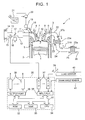
FIG. 1] FIG. 1 is an overall view of an internal combustion engine. - [
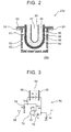
FIG. 2] FIG. 2 is a partially enlarged cross-sectional view of a sensor for detecting oxygen concentration or an air-fuel ratio. - [
FIG. 3] FIG. 3 is a schematic view of an electric circuit of the sensor for detecting oxygen concentration or an air-fuel ratio. - [
FIG. 4] FIG. 4 is a graph illustrating a relationship between an output current and an inter-electrode voltage of a sensor for detecting oxygen concentration or an air-fuel ratio according to an embodiment of the invention. - [
FIG. 5] FIG. 5 is a graph illustrating a relationship between an output current and an inter-electrode voltage of a linear characteristic air-fuel ratio sensor according to the related art. - [
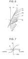
FIG. 6] FIG. 6 is a graph illustrating the relationship between the output current and the inter-electrode voltage of the sensor for detecting oxygen concentration or an air-fuel ratio according to the embodiment of the invention. - [
FIG. 7] FIG. 7 is a graph illustrating a relationship between the output current of the sensor for detecting oxygen concentration or an air-fuel ratio according to the embodiment of the invention and an air-fuel ratio. - [
FIG. 8] FIG. 8 is a flowchart for executing an air-fuel ratio control routine. - [
FIG. 9A] FIG. 9A is a graph illustrating a relationship between an output current of a sensor for detecting oxygen concentration or an air-fuel ratio and an air-fuel ratio. - [
FIG. 9B] FIG. 9B is a graph illustrating a relationship between an output current of a sensor for detecting oxygen concentration or an air-fuel ratio and an air-fuel ratio. - [
FIG. 10] FIG. 10 is a graph illustrating a reference current Is. - [
FIG. 11] FIG. 11 is a flowchart for executing an air-fuel ratio control routine according to another embodiment of the invention. - [
FIG. 12A] FIG. 12A is a graph illustrating a relationship between an output current and an inter-electrode voltage of a sensor for detecting oxygen concentration or an air-fuel ratio. - [
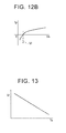
FIG. 12B] FIG. 12B is a graph illustrating a relationship between an output current and an inter-electrode voltage of a sensor for detecting oxygen concentration or an air-fuel ratio. - [
FIG. 13] FIG. 13 is a graph illustrating a reference voltage Vr. - [
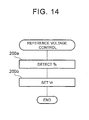
FIG. 14] FIG. 14 is a flowchart for executing a reference voltage control routine. -
FIG. 1 illustrates a case where the invention is applied to a spark-ignited internal combustion engine. However, the invention can also be applied to a compression-ignited internal combustion engine. - Referring to
FIG. 1, 1 represents an engine main body that is provided with, for example, four cylinders, 2 represents a cylinder block, 3 represents a cylinder head, 4 represents a piston, 5 represents a combustion chamber, 6 represents an intake valve, 7 represents an intake port, 8 represents an exhaust valve, 9 represents an exhaust port, and 10 represents a spark plug. Theintake port 7 is connected to asurge tank 12 via a correspondingintake branch pipe 11. Thesurge tank 12 is connected to anair cleaner 14 via anintake duct 13. Anair flow meter 15 for intake air amount detection and athrottle valve 17 that is driven by anactuator 16 are arranged in theintake duct 13. An electronically-controlledfuel injection valve 18 is arranged in each of theintake ports 7. Thefuel injection valves 18 are connected to afuel pump 20 via acommon rail 19 that is common to thefuel injection valves 18. Thefuel pump 20 is connected to afuel tank 21. - The
exhaust port 9 is connected to acatalytic converter 23 that has a relatively small capacity via anexhaust manifold 22. Thecatalytic converter 23 is connected to acatalytic converter 25 that has a relatively large capacity via anexhaust pipe 24. Thecatalytic converter 25 is connected to anexhaust pipe 26. Thecatalytic converters way catalysts sensor 27u for detecting oxygen concentration in exhaust gas or an air-fuel ratio is mounted on theexhaust manifold 22 on an upstream side of the three-way catalyst 23a. Asensor 27d for detecting oxygen concentration in exhaust gas or an air-fuel ratio is mounted on theexhaust pipe 24 on a downstream side of the three-way catalyst 23a. Hereinafter, thesensor 27u will be referred to as an upstream side sensor and thesensor 27d will be referred to as a downstream side sensor. - A digital computer constitutes an
electronic control unit 30. Theelectronic control unit 30 is provided with a read-only memory (ROM) 32, a random access memory (RAM) 33, a microprocessor (CPU) 34, aninput port 35, and anoutput port 36 connected to each other by abidirectional bus 31. Aload sensor 40 for detecting the amount of depression of anaccelerator pedal 39 is mounted on theaccelerator pedal 39. Output signals from theair flow meter 15, thesensor 27u, thesensor 27d, and theload sensor 40 are input to theinput port 35 viaAD converters 37 corresponding respectively thereto. In addition, acrank angle sensor 41, which generates an output pulse every time a crankshaft rotates at a predetermined angle, for example, 30 crank angle, is connected to theinput port 35. TheCPU 34 calculates an engine speed based on the output pulse from thecrank angle sensor 41. Theoutput port 36 is connected to each of thespark plug 10, theactuator 16, thefuel injection valve 18, and thefuel pump 20 via acorresponding drive circuit 38. -
FIG. 2 is a partially enlarged cross-sectional view of thedownstream side sensor 27d. Theupstream side sensor 27u is similar in configuration to thedownstream side sensor 27d. Regarding the upstream side sensor, a sensor that is different in configuration from thedownstream side sensor 27d can constitute 27u. - Referring to
FIG. 2 , 50 represents a housing, 51 represents a sensor element that is held by thehousing 50, and 52 represents a cover that has anopening 53. Thesensor element 51 is provided with a cup-shapedsolid electrolyte body 54, an exhaustgas side electrode 55 that is disposed on an outer surface of thesolid electrolyte body 54, and a referencegas side electrode 56 that is disposed on an inner surface of thesolid electrolyte body 54. Thesensor element 51 and the cover 52 are arranged in aninternal space 24a of theexhaust pipe 24. Accordingly, exhaust gas in theexhaust pipe 24 is introduced around thesensor element 51 via theopening 53 of the cover 52 and the exhaustgas side electrode 55 is in contact with the exhaust gas. Areference gas chamber 57 where reference gas is introduced is formed in an internal space of thesolid electrolyte body 54. Accordingly, the referencegas side electrode 56 is in contact with the reference gas. In the example that is illustrated inFIG. 2 , the reference gas is formed from the atmosphere. Accordingly, the referencegas side electrode 56 will also be referred to as an atmosphere side electrode. In the example that is illustrated inFIG. 2 , a solid electrolyte such as zirconia forms thesolid electrolyte body 54. A precious metal such as platinum forms theelectrodes - The exhaust
gas side electrode 55 is covered by a coating layer 58. The coating layer 58 is covered by a catalyst layer 59. The catalyst layer 59 is covered by atrap layer 60. The coating layer 58 protects the exhaustgas side electrode 55 and is formed of a porous ceramic such as a spinel. The catalyst layer 59 removes hydrogen in exhaust gas and is formed of a precious metal such as platinum supported on a porous ceramic such as alumina. Thetrap layer 60 captures a foreign matter in exhaust gas such as a deposit and is formed of a porous ceramic such as alumina. - As illustrated in
FIG. 3 , thedownstream side sensor 27d is also provided with anelectric circuit 70 that applies a voltage between theelectrodes FIG. 3 , theelectric circuit 70 is provided with an offsetelectric power supply 71 that applies an offset voltage Vo, a referenceelectric power supply 72 that applies a reference voltage Vr, anoperational amplifier 73 to which an electric power supply voltage Vb is applied, anelectric resistor 74 that applies an electric resistance R, and anoutput terminal 75. One side of the offsetelectric power supply 71 is connected to theatmosphere side electrode 56, which is a positive electrode, and the other side of the offsetelectric power supply 71 is connected to the referenceelectric power supply 72. The referenceelectric power supply 72 is connected to a +terminal of theoperational amplifier 73. One side of the exhaustgas side electrode 55, which is a negative electrode, is connected to one terminal of theoperational amplifier 73 and the other side of the exhaustgas side electrode 55 is connected to theoutput terminal 75 via theelectric resistor 74. Theoutput terminal 75 is input to the electronic control unit 30 (FIG. 1 ). Theelectronic control unit 30 detects an output voltage Eo, which is a potential at theoutput terminal 75. - The
electric circuit 70 applies a voltage between theelectrodes electrodes electrodes 
- The Equation (1) can be rewritten as the following Equation (2).
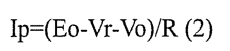
- In the embodiment that is illustrated in
FIG. 3 , the output voltage Eo is detected and the output current Ip is obtained by using the Equation (2). In another embodiment, the output current Ip is directly detected. InFIG. 3 , E and Ri represent an electromotive force and an internal resistance of thesolid electrolyte body 54, respectively (Vs=E+Ip·Ri). - In addition, the
downstream side sensor 27d is provided with a circuit that detects an impedance of thesensor element 51. The impedance of thesensor element 51 represents the temperature of thesensor element 51 or thedownstream side sensor 27d. - As described above, the exhaust gas is in contact with the exhaust
gas side electrode 55. Accordingly, HC and CO in the exhaust gas react with oxygen in the exhaustgas side electrode 55. As a result, the current Ip flows between theelectrodes -
FIG. 4 illustrates a relationship between the inter-electrode voltage Vs and the output current Ip of thedownstream side sensor 27d at a time when an air-fuel ratio is maintained at a theoretical air-fuel ratio. As seen inFIG. 4 , the output current Ip continues to increase as the inter-electrode voltage Vs is increased. - A linear characteristic air-fuel ratio sensor provided with a solid electrolyte body, an exhaust gas side electrode that is disposed on one side of the solid electrolyte body and is in contact with exhaust gas, a reference gas side electrode that is disposed on the other side of the solid electrolyte body and is in contact with reference gas, an electric circuit that applies a voltage between the electrodes, and a diffusion rate controlling layer that covers the exhaust gas side electrode is known.
FIG. 5 illustrates a relationship between an output current Ip' and an inter-electrode voltage Vs' of the linear characteristic air-fuel ratio sensor at a time when an air-fuel ratio is maintained at a theoretical air-fuel ratio. As illustrated inFIG. 5 , the output current Ip' increases as the inter-electrode voltage Vs' increases when the inter-electrode voltage Vs' is low. If the inter-electrode voltage Vs' further increases, the output current Ip' becomes substantially constant. If the inter-electrode voltage Vs' further increases, the output current Ip' increases as the inter-electrode voltage Vs' increases. The voltage region inFIG. 5 where the output current Ip' becomes substantially constant will be referred to as a limiting current region LC. The output current Ip' has the limiting current region LC as described above because the rate of the diffusion of the exhaust gas to the exhaust gas side electrode is controlled by the diffusion rate controlling layer. In a case where the output current Ip' has the limiting current region LC, the responsiveness of the air-fuel ratio sensor decreases and the output current Ip' may be hysteretic. - In contrast, the output current Ip of the
downstream side sensor 27d according to the embodiment of the invention has no limiting current region as illustrated inFIG. 4 . This is because thedownstream side sensor 27d according to the embodiment of the invention is provided with no diffusion rate controlling layer. As a result, the responsiveness of thedownstream side sensor 27d increases. In addition, the reference voltage Vr is applied between theelectrodes gas side electrode 55 is promoted. As a result, the output current Ip is not hysteretic. Accordingly, the air-fuel ratio can be accurately detected. - The coating layer 58 of the
downstream side sensor 27d according to the embodiment of the invention differs in configuration from the diffusion rate controlling layer of the linear characteristic air-fuel ratio sensor in that the output current Ip is formed to have no limiting current region. Specifically, for example, the coating layer 58 has a greater porosity than the diffusion rate controlling layer of the linear characteristic air-fuel ratio sensor. - In the invention, it is determined that the output current has a limiting current region in the event of (Ip(0.7 volt)-Ip(0.45 volt))/Ip(0.45 volt)<0.05 and |Ip(0.2 volt)-Ip(0.45 volt))| /Ip(0.45 volt)<0.05 when the output current Ip at the inter-electrode voltage Vs is represented by Ip(Vs). In contrast, it is determined that the output current has no limiting current region in the event of (Ip(0.7 volt)-Ip(0.45 volt))/Ip(0.45 volt)≥0.05 or |Ip(0.2 volt)-Ip(0.45 volt)) |/Ip(0.45 volt)≥0.05.
-
FIG. 6 illustrates the relationship between the output current Ip and the inter-electrode voltage Vs of thedownstream side sensor 27d according to the embodiment of the invention at various air-fuel ratios. InFIG. 6 , curves Ca, Cb, Cc, Cd, Ce, Cf, Cg, Ch, Ci show the output current Ip in a case where the air-fuel ratio is maintained at 12, 13, 14, theoretical air-fuel ratio (14.6), 15, 18, 25, and 40 each. A curve Cj shows the output current Ip in a case where the atmosphere is in contact with the exhaustgas side electrode 55. As seen inFIG. 6 , the output current Ip increases as the air-fuel ratio increases. -
FIG. 7 illustrates a relationship between an air-fuel ratio AF and the output current Ip of thedownstream side sensor 27d according to the embodiment of the invention in a case where the inter-electrode voltage Vs is maintained at the reference voltage Vr. As seen inFIG. 7 , the output current Ip increases as the air-fuel ratio AF increases. In addition, the output current Ip becomes equal to a reference current Is (>0) when the air-fuel ratio AF is equal to a reference air-fuel ratio. In the example that is illustrated inFIG. 7 , the reference air-fuel ratio is equal to the theoretical air-fuel ratio. - As described above, the oxygen concentration in the exhaust gas or the air-fuel ratio can be detected from the output current Ip of the
downstream side sensor 27d. In the embodiment of the invention, the air-fuel ratio AF is determined to be lower than a theoretical air-fuel ratio AFS, that is, to be richer than the theoretical air-fuel ratio AFS when the output current Ip is less than the reference current Is and the air-fuel ratio AF is determined to be higher than the theoretical air-fuel ratio AFS, that is, to be leaner than the theoretical air-fuel ratio AFS when the output current Ip is greater than the reference current Is. - Then, the air-fuel ratio is controlled based on the determination result. For example, the air-fuel ratio AF is controlled to be increased when the air-fuel ratio AF is determined to be lower than the theoretical air-fuel ratio AFS based on the output current Ip of the
downstream side sensor 27d and the air-fuel ratio AF is controlled to be decreased when the air-fuel ratio AF is determined to be higher than the theoretical air-fuel ratio AFS based on the output current Ip of thedownstream side sensor 27d. In this example, the air-fuel ratio AF is controlled with the theoretical air-fuel ratio AFS, that is, the reference air-fuel ratio being a target value. The air-fuel ratio AF is controlled by, for example, controlling a fuel injection amount or an intake air amount. - The reference voltage Vr is set so that a change in the output current Ip with respect to the air-fuel ratio AF near the reference air-fuel ratio increases. In this case, it can be more accurately detected whether the air-fuel ratio AF is lower or higher than the reference air-fuel ratio.
-
FIG. 8 illustrates a routine for executing the air-fuel ratio control described above. Referring toFIG. 8 , it is determined inStep 101 whether or not the output current Ip of thedownstream side sensor 27d is less than the reference current Is. The routine proceeds to Step 102 when Ip is less than Is, and the air-fuel ratio is controlled to be increased. The routine proceeds to Step 103 when Ip is equal to or greater than Is, and the air-fuel ratio is controlled to be decreased. - Next, another embodiment of the invention will be described. In the following description, differences from the embodiment that is illustrated in
FIGS. 1 to 8 will be described. -
FIG. 9A illustrates the output current Ip at a time when the temperature of thedownstream side sensor 27d is relatively low andFIG. 9B illustrates the output current Ip at a time when the temperature of thedownstream side sensor 27d is relatively high. As seen inFIGS. 9A and9B , the output current Ip increases as the temperature of thedownstream side sensor 27d increases. Accordingly, the detection may be erroneous if the air-fuel ratio is detected based on the constant reference current Is. - In this another embodiment of the invention, the reference current Is is set based on a temperature Ts of the
downstream side sensor 27d. Specifically, the reference current Is is set to increase as the temperature Ts of thedownstream side sensor 27d increases as illustrated inFIG. 10 . As a result, the air-fuel ratio can be accurately detected regardless of the temperature Ts of thedownstream side sensor 27d, and thus the air-fuel ratio can be accurately controlled. The reference current Is is stored in theROM 32 in advance in the form of the map that is illustrated inFIG. 10 . -
FIG. 11 illustrates a routine for executing air-fuel ratio control according to this another embodiment of the invention. Referring toFIG. 11 , the temperature Ts of thedownstream side sensor 27d is detected inStep 100a. Then, the reference current Is is calculated from the map ofFIG. 10 inStep 100b. Then, it is determined inStep 101 whether or not the output current Ip of thedownstream side sensor 27d is less than the reference current Is. The routine proceeds to Step 102 when Ip is less than Is, and the air-fuel ratio is controlled to be increased. The routine proceeds to Step 103 when Ip is equal to or greater than Is, and the air-fuel ratio is controlled to be decreased. - Next, yet another embodiment of the invention will be described. In the following description, differences from the embodiment that is illustrated in
FIGS. 1 to 8 will be described. - In the embodiment described above, the reference voltage Vr is set so that the reference current Is has a positive value. In contrast, the reference voltage Vr is set so that the reference current Is becomes zero in this yet another embodiment of the invention. In this case, a detection error can be reduced.
-
FIG. 12A illustrates a relationship between the output current Ip and the inter-electrode voltage Vs at a time when the temperature Ts of thedownstream side sensor 27d is relatively low andFIG. 12B illustrates a relationship between the output current Ip and the inter-electrode voltage Vs at a time when the temperature of thedownstream side sensor 27d is relatively high. As seen inFIGS. 12A and12B , the reference voltage Vr at which the output current Ip becomes zero decreases when the temperature of thedownstream side sensor 27d increases. Accordingly, the detection may be erroneous if the air-fuel ratio is detected based on the output current Ip detected while applying the constant reference voltage Vr. - In this yet another embodiment of the invention, the reference voltage Vr is set based on the temperature Ts of the
downstream side sensor 27d. Specifically, the reference voltage Vr is set to be decreased as the temperature Ts of thedownstream side sensor 27d increases as illustrated inFIG. 13 . As a result, the air-fuel ratio can be accurately detected regardless of the temperature Ts of thedownstream side sensor 27d, and thus the air-fuel ratio can be accurately controlled. The reference voltage Vr is stored in theROM 32 in advance in the form of the map that is illustrated inFIG. 13 . -
FIG. 14 illustrates a routine for executing reference voltage control according to this yet another embodiment of the invention. Referring toFIG. 14 , the temperature Ts of thedownstream side sensor 27d is detected inStep 200a. Then, the reference voltage Vr is calculated from the map ofFIG. 13 inStep 100b. In thedownstream side sensor 27d, the inter-electrode voltage Vs is maintained at the reference voltage Vr that is calculated in this manner. -
- 1
- Engine main body
- 22
- Exhaust manifold
- 24, 26
- Exhaust pipe
- 23a, 25a
- Three-way catalyst
- 27u, 27d
- Sensor for detecting oxygen concentration or air-fuel ratio
- 54
- Solid electrolyte body
- 55
- Exhaust gas side electrode
- 56
- Reference gas side electrode
- 70
- Electric circuit
Claims (9)
- A control device for an internal combustion engine, in which a sensor for detecting oxygen concentration in exhaust gas or an air-fuel ratio provided with a solid electrolyte body, an exhaust gas side electrode disposed on one side of the solid electrolyte body and being in contact with the exhaust gas, a reference gas side electrode disposed on the other side of the solid electrolyte body and being in contact with reference gas, and an electric circuit applying a reference voltage between the electrodes is arranged in an engine exhaust passage, the sensor for detecting the oxygen concentration or the air-fuel ratio has a characteristic in which an output current continues to increase without having a limiting current region when the voltage applied between the electrodes is increased while the air-fuel ratio is constant, and the air-fuel ratio is controlled based on the output current of the sensor for detecting the oxygen concentration or the air-fuel ratio.
- The control device for an internal combustion engine according to claim 1, wherein the sensor for detecting the oxygen concentration or the air-fuel ratio has a characteristic in which the output current increases as the air-fuel ratio increases.
- The control device for an internal combustion engine according to claim 2, wherein the air-fuel ratio is determined to be lower than a reference air-fuel ratio when the output current is less than a reference current corresponding to the reference air-fuel ratio, the air-fuel ratio is determined to be higher than the reference air-fuel ratio when the output current is greater than the reference current, and the air-fuel ratio is controlled based on the determination result.
- The control device for an internal combustion engine according to claim 3, wherein the reference current is set based on the temperature of the sensor for detecting the oxygen concentration or the air-fuel ratio.
- The control device for an internal combustion engine according to claim 4, wherein the reference current is set to increase as the temperature of the sensor for detecting the oxygen concentration or the air-fuel ratio increases.
- The control device for an internal combustion engine according to any one of claims 3 to 5,
wherein the reference air-fuel ratio is a theoretical air-fuel ratio. - The control device for an internal combustion engine according to any one of claims 3 to 6,
wherein the reference voltage is set so that the reference current has a positive value. - The control device for an internal combustion engine according to any one of claims 3 to 6,
wherein the reference voltage is set so that the reference current becomes zero. - The control device for an internal combustion engine according to any one of claims 1 to 8,
wherein the reference gas is the atmosphere.
Applications Claiming Priority (2)
| Application Number | Priority Date | Filing Date | Title |
|---|---|---|---|
| JP2013029168A JP5440724B1 (en) | 2013-02-18 | 2013-02-18 | Control device for internal combustion engine |
| PCT/JP2013/064524 WO2014125661A1 (en) | 2013-02-18 | 2013-05-24 | Device for controlling internal combustion engine |
Publications (3)
| Publication Number | Publication Date |
|---|---|
| EP2957904A1 true EP2957904A1 (en) | 2015-12-23 |
| EP2957904A4 EP2957904A4 (en) | 2016-12-14 |
| EP2957904B1 EP2957904B1 (en) | 2021-08-04 |
Family
ID=50396744
Family Applications (1)
| Application Number | Title | Priority Date | Filing Date |
|---|---|---|---|
| EP13875143.3A Active EP2957904B1 (en) | 2013-02-18 | 2013-05-24 | Device for controlling an internal combustion engine |
Country Status (8)
| Country | Link |
|---|---|
| US (1) | US10408149B2 (en) |
| EP (1) | EP2957904B1 (en) |
| JP (1) | JP5440724B1 (en) |
| KR (1) | KR101734737B1 (en) |
| CN (1) | CN105164525B (en) |
| BR (1) | BR112015011401A2 (en) |
| RU (1) | RU2603997C1 (en) |
| WO (1) | WO2014125661A1 (en) |
Families Citing this family (1)
| Publication number | Priority date | Publication date | Assignee | Title |
|---|---|---|---|---|
| JP6562047B2 (en) * | 2017-08-10 | 2019-08-21 | トヨタ自動車株式会社 | Exhaust gas purification device for internal combustion engine |
Family Cites Families (37)
| Publication number | Priority date | Publication date | Assignee | Title |
|---|---|---|---|---|
| DE2649272C2 (en) * | 1976-05-22 | 1986-04-03 | Robert Bosch Gmbh, 7000 Stuttgart | Control method and mixture ratio control device for determining the proportions of a fuel-air mixture fed to an internal combustion engine |
| JPS5820379B2 (en) * | 1976-12-28 | 1983-04-22 | 日産自動車株式会社 | Air fuel ratio control device |
| US4212066A (en) * | 1978-06-22 | 1980-07-08 | The Bendix Corporation | Hybrid electronic control unit for fuel management systems |
| JPS56122950A (en) * | 1980-03-03 | 1981-09-26 | Nissan Motor Co Ltd | Supplying circuit for controlling current for oxygen partial pressure on reference pole for oxygen sensor element |
| US4566419A (en) * | 1983-08-20 | 1986-01-28 | Nippondenso Co., Ltd. | Apparatus and method for controlling air-to-fuel ratio for an internal combustion engine |
| JPS6086457A (en) * | 1983-10-19 | 1985-05-16 | Hitachi Ltd | Air fuel ratio sensor for controlling engine |
| CA1223641A (en) * | 1984-03-05 | 1987-06-30 | Olivier De Pous | Device for generating an electric signal linearly dependent upon the oxygen content of a gaseous mixture |
| JPS61164148A (en) * | 1985-01-16 | 1986-07-24 | Japan Electronic Control Syst Co Ltd | Oxygen sensor element |
| JPH0643982B2 (en) * | 1985-10-14 | 1994-06-08 | 株式会社日立製作所 | Internal combustion engine controller |
| JPS62145161A (en) * | 1985-12-19 | 1987-06-29 | Sanyo Electric Co Ltd | Oxygen sensor |
| JPH0760141B2 (en) * | 1988-10-11 | 1995-06-28 | 株式会社日立製作所 | Air-fuel ratio controller for engine |
| JPH0413961A (en) | 1990-05-07 | 1992-01-17 | Toyota Motor Corp | Air/fuel ratio detector |
| JP2880273B2 (en) * | 1990-08-20 | 1999-04-05 | 株式会社日本自動車部品総合研究所 | Oxygen concentration detector |
| JP3467808B2 (en) * | 1992-12-02 | 2003-11-17 | 株式会社デンソー | Oxygen concentration determination device |
| DE4340875A1 (en) * | 1993-12-01 | 1995-06-08 | Bosch Gmbh Robert | Oxygen sensor |
| JP3711582B2 (en) * | 1995-03-31 | 2005-11-02 | 株式会社デンソー | Oxygen concentration detector |
| JP2812247B2 (en) * | 1995-06-01 | 1998-10-22 | トヨタ自動車株式会社 | Active state determination device for air-fuel ratio sensor |
| JP3684686B2 (en) | 1995-12-18 | 2005-08-17 | 株式会社デンソー | Oxygen concentration determination device |
| RU2092827C1 (en) * | 1995-12-29 | 1997-10-10 | Государственное предприятие Техноцентр "Лазерная диагностика и чистые технологии" Научно-исследовательского и конструкторского института энерготехники | Device for measuring of partial pressure of oxygen and process of its manufacture |
| JPH09196889A (en) | 1996-01-16 | 1997-07-31 | Toyota Motor Corp | Air-fuel ratio detector |
| US6055972A (en) | 1996-07-04 | 2000-05-02 | Denso Corporation | Air fuel ratio control apparatus having air-fuel ratio control point switching function |
| JP4051725B2 (en) | 1996-07-19 | 2008-02-27 | 株式会社デンソー | Air-fuel ratio control method |
| US6382015B1 (en) | 1998-06-11 | 2002-05-07 | Toyota Jidosha Kabushiki Kaisha | Air-fuel ratio sensor resistance detecting apparatus |
| JP3646566B2 (en) | 1998-06-11 | 2005-05-11 | トヨタ自動車株式会社 | Resistance detection device for air-fuel ratio sensor |
| JP2000111512A (en) | 1998-10-02 | 2000-04-21 | Fujikura Ltd | Driving method of limiting current type oxygen sensor |
| US6440283B1 (en) * | 1998-12-02 | 2002-08-27 | Georgia Tech Research Corporation | Oxygen sensor and emission control system |
| JP3975599B2 (en) * | 1999-02-19 | 2007-09-12 | 株式会社デンソー | Gas concentration detector |
| JP2002022699A (en) | 2000-07-07 | 2002-01-23 | Unisia Jecs Corp | Device temperature estimation device for air-fuel ratio sensor |
| JP4595264B2 (en) * | 2000-10-05 | 2010-12-08 | 株式会社デンソー | Oxygen sensor element and manufacturing method thereof |
| JP4007385B2 (en) | 2003-09-01 | 2007-11-14 | トヨタ自動車株式会社 | Exhaust gas sensor control device |
| JP4631517B2 (en) | 2005-04-13 | 2011-02-16 | トヨタ自動車株式会社 | Oxygen sensor and air-fuel ratio control system |
| JP4805734B2 (en) | 2006-06-27 | 2011-11-02 | 日本特殊陶業株式会社 | Sensor element deterioration determination device and sensor element deterioration determination method |
| JP4725481B2 (en) | 2006-10-16 | 2011-07-13 | トヨタ自動車株式会社 | Air-fuel ratio control device |
| JP2009121401A (en) | 2007-11-16 | 2009-06-04 | Toyota Motor Corp | The present invention relates to an exhaust temperature estimation device for an internal combustion engine. |
| JP4974936B2 (en) * | 2008-03-05 | 2012-07-11 | 日本特殊陶業株式会社 | Inspection method of gas sensor element |
| JP5166354B2 (en) * | 2009-06-05 | 2013-03-21 | 日本特殊陶業株式会社 | Gas sensor element and gas sensor |
| JP5360312B1 (en) | 2013-01-29 | 2013-12-04 | トヨタ自動車株式会社 | Control device for internal combustion engine |
-
2013
- 2013-02-18 JP JP2013029168A patent/JP5440724B1/en not_active Expired - Fee Related
- 2013-05-24 CN CN201380058124.9A patent/CN105164525B/en not_active Expired - Fee Related
- 2013-05-24 EP EP13875143.3A patent/EP2957904B1/en active Active
- 2013-05-24 US US14/441,681 patent/US10408149B2/en not_active Expired - Fee Related
- 2013-05-24 WO PCT/JP2013/064524 patent/WO2014125661A1/en not_active Ceased
- 2013-05-24 BR BR112015011401A patent/BR112015011401A2/en not_active Application Discontinuation
- 2013-05-24 RU RU2015117035/28A patent/RU2603997C1/en not_active IP Right Cessation
- 2013-05-24 KR KR1020157011289A patent/KR101734737B1/en not_active Expired - Fee Related
Also Published As
| Publication number | Publication date |
|---|---|
| RU2603997C1 (en) | 2016-12-10 |
| EP2957904B1 (en) | 2021-08-04 |
| US20150337752A1 (en) | 2015-11-26 |
| EP2957904A4 (en) | 2016-12-14 |
| CN105164525A (en) | 2015-12-16 |
| BR112015011401A2 (en) | 2017-07-11 |
| JP5440724B1 (en) | 2014-03-12 |
| JP2014156846A (en) | 2014-08-28 |
| US10408149B2 (en) | 2019-09-10 |
| KR101734737B1 (en) | 2017-05-11 |
| WO2014125661A1 (en) | 2014-08-21 |
| CN105164525B (en) | 2018-01-19 |
| KR20150056662A (en) | 2015-05-26 |
Similar Documents
| Publication | Publication Date | Title |
|---|---|---|
| AU2013376226B2 (en) | Control device for internal combustion engine | |
| US10156200B2 (en) | Abnormality diagnosis system of downstream side air-fuel ratio sensor | |
| US8418439B2 (en) | NOx sensor ambient temperature compensation | |
| WO2014118889A1 (en) | Control device for internal combustion engine | |
| CN107110043B (en) | Oil dilution ratio calculation system for internal combustion engine | |
| EP2952714B1 (en) | Control device for internal combustion engine | |
| KR20150099839A (en) | Control device for internal combustion engine | |
| US10001076B2 (en) | Control system of internal combustion engine | |
| US9594049B2 (en) | Gas sensor control apparatus | |
| US10473049B2 (en) | Control system of internal combustion engine | |
| US20180003119A1 (en) | Exhaust sensor | |
| EP2957904B1 (en) | Device for controlling an internal combustion engine | |
| US7275364B2 (en) | Exhaust emission control device of internal combustion engine | |
| JP2015105843A (en) | Gas sensor control device | |
| JP6562047B2 (en) | Exhaust gas purification device for internal combustion engine | |
| JP2020197201A (en) | Air-fuel ratio detection system | |
| JP6734019B2 (en) | Abnormality diagnosis device for downstream air-fuel ratio sensor | |
| JP2017075794A (en) | Sensor control device | |
| JP2018059941A (en) | Gas sensor control device |
Legal Events
| Date | Code | Title | Description |
|---|---|---|---|
| PUAI | Public reference made under article 153(3) epc to a published international application that has entered the european phase |
Free format text: ORIGINAL CODE: 0009012 |
|
| 17P | Request for examination filed |
Effective date: 20150507 |
|
| AK | Designated contracting states |
Kind code of ref document: A1 Designated state(s): AL AT BE BG CH CY CZ DE DK EE ES FI FR GB GR HR HU IE IS IT LI LT LU LV MC MK MT NL NO PL PT RO RS SE SI SK SM TR |
|
| AX | Request for extension of the european patent |
Extension state: BA ME |
|
| DAX | Request for extension of the european patent (deleted) | ||
| A4 | Supplementary search report drawn up and despatched |
Effective date: 20161114 |
|
| RIC1 | Information provided on ipc code assigned before grant |
Ipc: F02D 41/14 20060101ALI20161108BHEP Ipc: G01N 27/409 20060101AFI20161108BHEP Ipc: G01N 27/406 20060101ALN20161108BHEP Ipc: G01N 27/407 20060101ALI20161108BHEP Ipc: G01N 27/41 20060101ALI20161108BHEP |
|
| STAA | Information on the status of an ep patent application or granted ep patent |
Free format text: STATUS: EXAMINATION IS IN PROGRESS |
|
| 17Q | First examination report despatched |
Effective date: 20200430 |
|
| GRAP | Despatch of communication of intention to grant a patent |
Free format text: ORIGINAL CODE: EPIDOSNIGR1 |
|
| STAA | Information on the status of an ep patent application or granted ep patent |
Free format text: STATUS: GRANT OF PATENT IS INTENDED |
|
| RIC1 | Information provided on ipc code assigned before grant |
Ipc: G01N 27/406 20060101ALN20210129BHEP Ipc: G01N 27/41 20060101ALI20210129BHEP Ipc: G01N 27/407 20060101ALI20210129BHEP Ipc: F02D 41/14 20060101ALI20210129BHEP Ipc: G01N 27/409 20060101AFI20210129BHEP |
|
| RIC1 | Information provided on ipc code assigned before grant |
Ipc: G01N 27/41 20060101ALI20210224BHEP Ipc: G01N 27/407 20060101ALI20210224BHEP Ipc: F02D 41/14 20060101ALI20210224BHEP Ipc: G01N 27/406 20060101ALN20210224BHEP Ipc: G01N 27/409 20060101AFI20210224BHEP |
|
| INTG | Intention to grant announced |
Effective date: 20210310 |
|
| GRAS | Grant fee paid |
Free format text: ORIGINAL CODE: EPIDOSNIGR3 |
|
| GRAA | (expected) grant |
Free format text: ORIGINAL CODE: 0009210 |
|
| STAA | Information on the status of an ep patent application or granted ep patent |
Free format text: STATUS: THE PATENT HAS BEEN GRANTED |
|
| AK | Designated contracting states |
Kind code of ref document: B1 Designated state(s): AL AT BE BG CH CY CZ DE DK EE ES FI FR GB GR HR HU IE IS IT LI LT LU LV MC MK MT NL NO PL PT RO RS SE SI SK SM TR |
|
| REG | Reference to a national code |
Ref country code: GB Ref legal event code: FG4D |
|
| REG | Reference to a national code |
Ref country code: AT Ref legal event code: REF Ref document number: 1417474 Country of ref document: AT Kind code of ref document: T Effective date: 20210815 |
|
| REG | Reference to a national code |
Ref country code: CH Ref legal event code: EP |
|
| REG | Reference to a national code |
Ref country code: DE Ref legal event code: R096 Ref document number: 602013078690 Country of ref document: DE |
|
| REG | Reference to a national code |
Ref country code: IE Ref legal event code: FG4D |
|
| REG | Reference to a national code |
Ref country code: LT Ref legal event code: MG9D |
|
| REG | Reference to a national code |
Ref country code: NL Ref legal event code: MP Effective date: 20210804 |
|
| REG | Reference to a national code |
Ref country code: AT Ref legal event code: MK05 Ref document number: 1417474 Country of ref document: AT Kind code of ref document: T Effective date: 20210804 |
|
| PG25 | Lapsed in a contracting state [announced via postgrant information from national office to epo] |
Ref country code: PT Free format text: LAPSE BECAUSE OF FAILURE TO SUBMIT A TRANSLATION OF THE DESCRIPTION OR TO PAY THE FEE WITHIN THE PRESCRIBED TIME-LIMIT Effective date: 20211206 Ref country code: NO Free format text: LAPSE BECAUSE OF FAILURE TO SUBMIT A TRANSLATION OF THE DESCRIPTION OR TO PAY THE FEE WITHIN THE PRESCRIBED TIME-LIMIT Effective date: 20211104 Ref country code: FI Free format text: LAPSE BECAUSE OF FAILURE TO SUBMIT A TRANSLATION OF THE DESCRIPTION OR TO PAY THE FEE WITHIN THE PRESCRIBED TIME-LIMIT Effective date: 20210804 Ref country code: ES Free format text: LAPSE BECAUSE OF FAILURE TO SUBMIT A TRANSLATION OF THE DESCRIPTION OR TO PAY THE FEE WITHIN THE PRESCRIBED TIME-LIMIT Effective date: 20210804 Ref country code: AT Free format text: LAPSE BECAUSE OF FAILURE TO SUBMIT A TRANSLATION OF THE DESCRIPTION OR TO PAY THE FEE WITHIN THE PRESCRIBED TIME-LIMIT Effective date: 20210804 Ref country code: BG Free format text: LAPSE BECAUSE OF FAILURE TO SUBMIT A TRANSLATION OF THE DESCRIPTION OR TO PAY THE FEE WITHIN THE PRESCRIBED TIME-LIMIT Effective date: 20211104 Ref country code: LT Free format text: LAPSE BECAUSE OF FAILURE TO SUBMIT A TRANSLATION OF THE DESCRIPTION OR TO PAY THE FEE WITHIN THE PRESCRIBED TIME-LIMIT Effective date: 20210804 Ref country code: SE Free format text: LAPSE BECAUSE OF FAILURE TO SUBMIT A TRANSLATION OF THE DESCRIPTION OR TO PAY THE FEE WITHIN THE PRESCRIBED TIME-LIMIT Effective date: 20210804 Ref country code: RS Free format text: LAPSE BECAUSE OF FAILURE TO SUBMIT A TRANSLATION OF THE DESCRIPTION OR TO PAY THE FEE WITHIN THE PRESCRIBED TIME-LIMIT Effective date: 20210804 Ref country code: HR Free format text: LAPSE BECAUSE OF FAILURE TO SUBMIT A TRANSLATION OF THE DESCRIPTION OR TO PAY THE FEE WITHIN THE PRESCRIBED TIME-LIMIT Effective date: 20210804 |
|
| PG25 | Lapsed in a contracting state [announced via postgrant information from national office to epo] |
Ref country code: PL Free format text: LAPSE BECAUSE OF FAILURE TO SUBMIT A TRANSLATION OF THE DESCRIPTION OR TO PAY THE FEE WITHIN THE PRESCRIBED TIME-LIMIT Effective date: 20210804 Ref country code: LV Free format text: LAPSE BECAUSE OF FAILURE TO SUBMIT A TRANSLATION OF THE DESCRIPTION OR TO PAY THE FEE WITHIN THE PRESCRIBED TIME-LIMIT Effective date: 20210804 Ref country code: GR Free format text: LAPSE BECAUSE OF FAILURE TO SUBMIT A TRANSLATION OF THE DESCRIPTION OR TO PAY THE FEE WITHIN THE PRESCRIBED TIME-LIMIT Effective date: 20211105 |
|
| PG25 | Lapsed in a contracting state [announced via postgrant information from national office to epo] |
Ref country code: NL Free format text: LAPSE BECAUSE OF FAILURE TO SUBMIT A TRANSLATION OF THE DESCRIPTION OR TO PAY THE FEE WITHIN THE PRESCRIBED TIME-LIMIT Effective date: 20210804 |
|
| PG25 | Lapsed in a contracting state [announced via postgrant information from national office to epo] |
Ref country code: DK Free format text: LAPSE BECAUSE OF FAILURE TO SUBMIT A TRANSLATION OF THE DESCRIPTION OR TO PAY THE FEE WITHIN THE PRESCRIBED TIME-LIMIT Effective date: 20210804 |
|
| REG | Reference to a national code |
Ref country code: DE Ref legal event code: R097 Ref document number: 602013078690 Country of ref document: DE |
|
| PG25 | Lapsed in a contracting state [announced via postgrant information from national office to epo] |
Ref country code: SM Free format text: LAPSE BECAUSE OF FAILURE TO SUBMIT A TRANSLATION OF THE DESCRIPTION OR TO PAY THE FEE WITHIN THE PRESCRIBED TIME-LIMIT Effective date: 20210804 Ref country code: SK Free format text: LAPSE BECAUSE OF FAILURE TO SUBMIT A TRANSLATION OF THE DESCRIPTION OR TO PAY THE FEE WITHIN THE PRESCRIBED TIME-LIMIT Effective date: 20210804 Ref country code: RO Free format text: LAPSE BECAUSE OF FAILURE TO SUBMIT A TRANSLATION OF THE DESCRIPTION OR TO PAY THE FEE WITHIN THE PRESCRIBED TIME-LIMIT Effective date: 20210804 Ref country code: EE Free format text: LAPSE BECAUSE OF FAILURE TO SUBMIT A TRANSLATION OF THE DESCRIPTION OR TO PAY THE FEE WITHIN THE PRESCRIBED TIME-LIMIT Effective date: 20210804 Ref country code: CZ Free format text: LAPSE BECAUSE OF FAILURE TO SUBMIT A TRANSLATION OF THE DESCRIPTION OR TO PAY THE FEE WITHIN THE PRESCRIBED TIME-LIMIT Effective date: 20210804 Ref country code: AL Free format text: LAPSE BECAUSE OF FAILURE TO SUBMIT A TRANSLATION OF THE DESCRIPTION OR TO PAY THE FEE WITHIN THE PRESCRIBED TIME-LIMIT Effective date: 20210804 |
|
| PLBE | No opposition filed within time limit |
Free format text: ORIGINAL CODE: 0009261 |
|
| STAA | Information on the status of an ep patent application or granted ep patent |
Free format text: STATUS: NO OPPOSITION FILED WITHIN TIME LIMIT |
|
| 26N | No opposition filed |
Effective date: 20220506 |
|
| PG25 | Lapsed in a contracting state [announced via postgrant information from national office to epo] |
Ref country code: IT Free format text: LAPSE BECAUSE OF FAILURE TO SUBMIT A TRANSLATION OF THE DESCRIPTION OR TO PAY THE FEE WITHIN THE PRESCRIBED TIME-LIMIT Effective date: 20210804 |
|
| PGFP | Annual fee paid to national office [announced via postgrant information from national office to epo] |
Ref country code: FR Payment date: 20220408 Year of fee payment: 10 Ref country code: DE Payment date: 20220329 Year of fee payment: 10 |
|
| PG25 | Lapsed in a contracting state [announced via postgrant information from national office to epo] |
Ref country code: SI Free format text: LAPSE BECAUSE OF FAILURE TO SUBMIT A TRANSLATION OF THE DESCRIPTION OR TO PAY THE FEE WITHIN THE PRESCRIBED TIME-LIMIT Effective date: 20210804 |
|
| REG | Reference to a national code |
Ref country code: CH Ref legal event code: PL |
|
| REG | Reference to a national code |
Ref country code: BE Ref legal event code: MM Effective date: 20220531 |
|
| GBPC | Gb: european patent ceased through non-payment of renewal fee |
Effective date: 20220524 |
|
| PG25 | Lapsed in a contracting state [announced via postgrant information from national office to epo] |
Ref country code: MC Free format text: LAPSE BECAUSE OF FAILURE TO SUBMIT A TRANSLATION OF THE DESCRIPTION OR TO PAY THE FEE WITHIN THE PRESCRIBED TIME-LIMIT Effective date: 20210804 Ref country code: LU Free format text: LAPSE BECAUSE OF NON-PAYMENT OF DUE FEES Effective date: 20220524 Ref country code: LI Free format text: LAPSE BECAUSE OF NON-PAYMENT OF DUE FEES Effective date: 20220531 Ref country code: CH Free format text: LAPSE BECAUSE OF NON-PAYMENT OF DUE FEES Effective date: 20220531 |
|
| PG25 | Lapsed in a contracting state [announced via postgrant information from national office to epo] |
Ref country code: IE Free format text: LAPSE BECAUSE OF NON-PAYMENT OF DUE FEES Effective date: 20220524 |
|
| PG25 | Lapsed in a contracting state [announced via postgrant information from national office to epo] |
Ref country code: GB Free format text: LAPSE BECAUSE OF NON-PAYMENT OF DUE FEES Effective date: 20220524 Ref country code: BE Free format text: LAPSE BECAUSE OF NON-PAYMENT OF DUE FEES Effective date: 20220531 |
|
| P01 | Opt-out of the competence of the unified patent court (upc) registered |
Effective date: 20230427 |
|
| REG | Reference to a national code |
Ref country code: DE Ref legal event code: R119 Ref document number: 602013078690 Country of ref document: DE |
|
| PG25 | Lapsed in a contracting state [announced via postgrant information from national office to epo] |
Ref country code: HU Free format text: LAPSE BECAUSE OF FAILURE TO SUBMIT A TRANSLATION OF THE DESCRIPTION OR TO PAY THE FEE WITHIN THE PRESCRIBED TIME-LIMIT; INVALID AB INITIO Effective date: 20130524 |
|
| PG25 | Lapsed in a contracting state [announced via postgrant information from national office to epo] |
Ref country code: MK Free format text: LAPSE BECAUSE OF FAILURE TO SUBMIT A TRANSLATION OF THE DESCRIPTION OR TO PAY THE FEE WITHIN THE PRESCRIBED TIME-LIMIT Effective date: 20210804 Ref country code: DE Free format text: LAPSE BECAUSE OF NON-PAYMENT OF DUE FEES Effective date: 20231201 Ref country code: CY Free format text: LAPSE BECAUSE OF FAILURE TO SUBMIT A TRANSLATION OF THE DESCRIPTION OR TO PAY THE FEE WITHIN THE PRESCRIBED TIME-LIMIT Effective date: 20210804 |
|
| PG25 | Lapsed in a contracting state [announced via postgrant information from national office to epo] |
Ref country code: FR Free format text: LAPSE BECAUSE OF NON-PAYMENT OF DUE FEES Effective date: 20230531 |
|
| PG25 | Lapsed in a contracting state [announced via postgrant information from national office to epo] |
Ref country code: TR Free format text: LAPSE BECAUSE OF FAILURE TO SUBMIT A TRANSLATION OF THE DESCRIPTION OR TO PAY THE FEE WITHIN THE PRESCRIBED TIME-LIMIT Effective date: 20210804 |
|
| PG25 | Lapsed in a contracting state [announced via postgrant information from national office to epo] |
Ref country code: MT Free format text: LAPSE BECAUSE OF FAILURE TO SUBMIT A TRANSLATION OF THE DESCRIPTION OR TO PAY THE FEE WITHIN THE PRESCRIBED TIME-LIMIT Effective date: 20210804 |