EP2957896A1 - Dispositif optique de conduite d'un faisceau de rayons et écran destiné à être installé dans celui-ci - Google Patents
Dispositif optique de conduite d'un faisceau de rayons et écran destiné à être installé dans celui-ci Download PDFInfo
- Publication number
- EP2957896A1 EP2957896A1 EP14172737.0A EP14172737A EP2957896A1 EP 2957896 A1 EP2957896 A1 EP 2957896A1 EP 14172737 A EP14172737 A EP 14172737A EP 2957896 A1 EP2957896 A1 EP 2957896A1
- Authority
- EP
- European Patent Office
- Prior art keywords
- diaphragm
- aperture
- passage opening
- mating surface
- opening
- Prior art date
- Legal status (The legal status is an assumption and is not a legal conclusion. Google has not performed a legal analysis and makes no representation as to the accuracy of the status listed.)
- Ceased
Links
Images
Classifications
-
- G—PHYSICS
- G01—MEASURING; TESTING
- G01N—INVESTIGATING OR ANALYSING MATERIALS BY DETERMINING THEIR CHEMICAL OR PHYSICAL PROPERTIES
- G01N21/00—Investigating or analysing materials by the use of optical means, i.e. using sub-millimetre waves, infrared, visible or ultraviolet light
- G01N21/17—Systems in which incident light is modified in accordance with the properties of the material investigated
- G01N21/47—Scattering, i.e. diffuse reflection
- G01N21/49—Scattering, i.e. diffuse reflection within a body or fluid
- G01N21/51—Scattering, i.e. diffuse reflection within a body or fluid inside a container, e.g. in an ampoule
-
- G—PHYSICS
- G02—OPTICS
- G02B—OPTICAL ELEMENTS, SYSTEMS OR APPARATUS
- G02B5/00—Optical elements other than lenses
- G02B5/003—Light absorbing elements
-
- G—PHYSICS
- G02—OPTICS
- G02B—OPTICAL ELEMENTS, SYSTEMS OR APPARATUS
- G02B5/00—Optical elements other than lenses
- G02B5/005—Diaphragms
-
- G—PHYSICS
- G01—MEASURING; TESTING
- G01N—INVESTIGATING OR ANALYSING MATERIALS BY DETERMINING THEIR CHEMICAL OR PHYSICAL PROPERTIES
- G01N21/00—Investigating or analysing materials by the use of optical means, i.e. using sub-millimetre waves, infrared, visible or ultraviolet light
- G01N21/17—Systems in which incident light is modified in accordance with the properties of the material investigated
- G01N21/47—Scattering, i.e. diffuse reflection
- G01N2021/4704—Angular selective
- G01N2021/4707—Forward scatter; Low angle scatter
-
- G—PHYSICS
- G02—OPTICS
- G02B—OPTICAL ELEMENTS, SYSTEMS OR APPARATUS
- G02B7/00—Mountings, adjusting means, or light-tight connections, for optical elements
- G02B7/006—Filter holders
Definitions
- the invention relates to an optical device for guiding a beam, which has a housing with a channel in which the beam path extends, wherein in the beam path, a diaphragm is arranged.
- the channel serves to guide the beam, which is used for optical examination, for example, a sample.
- the invention relates to a diaphragm.
- Such diaphragms are also incorporated in particular in optical devices of the type specified, so that certain light components can be hidden when the beam is conducted.
- Today's analyzers are capable of performing a variety of detection reactions and analyzes on a sample.
- various devices for the spatial transfer of measuring cells, reaction vessels and reagent containers are required, such.
- B. pipetting devices It is also, as in the DE 10 2009 043 524 A1 described, possible to perform the measuring device of the analyzer movable, while the measuring cells remain immovable in their recording devices.
- Suitable devices include a control unit, which is by means of appropriate software to be able to largely independently plan the work steps for the desired analysis and work off.
- a device in the context of this invention, allows a fixation of the measuring cell and on the other hand includes the space required for the measuring cell. Through this space, which is to be understood as part of the recording device, also runs the beam of the measuring light.
- the measuring cell can be exchangeable or permanently fixed in the receiving device. A permanent fixation also allows integration of the measuring cell into the analyzer.
- optical methods enable the qualitative and quantitative detection of analytes, i. the substances or particles to be detected or determined, in samples.
- the determination of clinically relevant parameters, such as the concentration or activity of an analyte is often accomplished by mixing a portion of a sample with one or more test reagents in a reaction vessel, which may also be the measuring cell, thereby obtaining e.g. initiating a biochemical reaction or a specific binding reaction that causes a measurable change in an optical or other physical property of the assay.
- the concentration of finely divided, colloidal particles in liquids or gases can be determined quantitatively: If a suspension of small particles is brought into a light beam, a part of the light of the beam of the light beam is absorbed, another part, also called a primary beam, leaves the suspension unscrewed and another part is scattered laterally to the incoming beam. In nephelometry, this laterally emerging scattered light is measured. As a beam in the context of this application, the light of a laser steel to be understood.
- Nephelometry is used primarily for the quantitative or qualitative detection of analytes, for example proteins, which preferably are obtained by means of a specific binding reaction between two specific binding partners, e.g. by antigen-antibody binding.
- Quantitative detection measures the amount, concentration or activity of the analyte in the sample.
- the term "quantitative detection” also includes semiquantitative methods which can only capture the approximate amount, concentration or activity of the analyte in the sample or can only serve for a relative indication of quantity, concentration or activity.
- qualitative detection is meant detecting the presence of the analyte in the sample at all, or indicating that the amount, concentration or activity of the analyte in the sample is below or above a certain threshold (s).
- a nephelometric system includes, as in the DE 198 49 597 A1 described, usually at least one means for generating a beam comprising a light source, and at least one photodetector and at least one receiving device for a measuring cell.
- the light source, the pickup device and the photodetector may be arranged such that the photodetector detects the scattered light at angles or angular ranges around the propagation direction of the light beam emitted from the light source in which the intensity of the scattered light is relatively high.
- the photodetector not only reaches the scattered light, but also the primary beam.
- an optical aperture is used. This is held by means of thin webs in the beam path and adapted in size and shape so that it hides as much of the primary beam as possible so that as far as possible only stray light strikes the detector. According to the DE 36 08 552 A1 Further apertures can be used to separate the scattered light even better from the light of the primary steel.
- the panels For the panels to work as accurately as possible, they must be aligned very precisely in the housing which provides the channel. This requires a certain manufacturing effort to manufacture the parts and assembly costs when inserting the panel in the housing.
- the object of the invention is to provide the optical device specified at the outset or an aperture suitable for use in this device, with which the manufacturing outlay and the assembly effort can be reduced.
- the housing has a passage opening in a wall defining the channel for guiding the beam, through which the diaphragm can be inserted from outside the channel in this.
- the passage opening has at least one mating surface against which the diaphragm abuts and which defines the position of the diaphragm in a spatial direction. Due to the mating surface, it is advantageously possible to fix the diaphragm in the spatial direction predetermined by the mating surface during assembly, so that clear positioning of the diaphragm results after installation in this spatial direction.
- the passage opening can be introduced into the housing after its production. This can advantageously be done, for example, by cutting methods such as drilling or milling.
- the passage opening can be aligned with the planned beam path of the beam, wherein manufacturing tolerances of the housing are eliminated.
- the beam path of the beam is also guided by other optical devices, such as collection optics. Even with respect to these optical elements a clear alignment is possible, whereby the interaction of all optical devices is ensured.
- the passage opening is made larger than the projection of the aperture in the mounting direction, ie insertion direction of the same. This ensures that the panel can be easily inserted into the passage opening, with only the mating surfaces are designed so that they touch the panel in the installed state.
- the passage opening has a mating surface or two opposing mating surfaces which define the diaphragm perpendicular to the beam axis of the beam path and perpendicular to the insertion direction of the diaphragm (this direction can be defined as the y direction in the Cartesian coordinate system) , By fixing the diaphragm in this direction, it is advantageously achieved that the diaphragm is clearly defined in a spatial direction lateral to the beam alignment.
- the passage opening has a mating surface which defines the aperture in the insertion direction of the diaphragm (defined as x-direction). This mating surface can for example be designed as a stop that limits the insertion movement. As a result, the lateral position of the diaphragm in the beam path in a spatial direction is determined perpendicular to the already specified spatial direction.
- a further opening is provided in the wall delimiting the channel in the insertion direction, wherein the further opening has at least one mating surface against which the diaphragm rests and the position of the diaphragm in one spatial direction sets.
- the additional opening does not have to be a passage opening since the aperture on the opposite side of the channel does not have to protrude out of the wall.
- the bottom of the opening may represent a mating surface in the insertion direction (ie x-direction), as has already been described for the passage opening.
- the further opening can also have a mating surface or two opposing mating surfaces which define the diaphragm perpendicular to the beam axis of the beam path and perpendicular to the insertion direction of the diaphragm (ie in the y direction). With this mating surface and possibly by providing an opening bottom in the further opening, the already described definition of the position of the diaphragm in two mutually perpendicular spatial directions (the xy plane) laterally to the beam path is possible.
- the passage opening has a mating surface or two opposing mating surfaces which define the aperture in the direction of the beam axis of the beam path (ie in the z direction).
- the further opening has a mating surface or two opposing mating surfaces which define the aperture in the direction of the beam axis of the beam path.
- the diaphragm is namely determined in its axial position and can be arranged, for example, exactly in a focal point.
- the exact positioning of the diaphragm makes it possible, especially in this case, that the Aperture advantageously advantageous can be chosen comparatively small.
- the passage opening and / or the further opening are closed with a material.
- This material may be, for example, a potting compound.
- the use of such a material has the advantage that the panel is permanently fixed in this positioning after mounting and alignment with the mating surfaces. In addition, it can be prevented that impurities can pass through the passage opening or further opening into the interior of the channel.
- the passage opening and / or the further opening can advantageously be designed as drilling or milling holes.
- these methods can be advantageously produce mating surfaces that have a sufficiently good surface quality, so that they do not need to be reworked.
- the drilling or milling tools can be approached with sufficient accuracy to the device, so that a closely tolerated production of mating surfaces is possible.
- the intended beam path of the beam is selected as the reference system for the alignment of the tools.
- a mating surfaces can serve the hole walls, which can be obtained in particular by radial guiding a milling head flat surface portions.
- the perforated plates of drilling or milling holes can be used are, since the axial movement of the tools of the subsequent insertion direction of the diaphragm correspond.
- the device can be used advantageously as Streuloismessytem, in particular as Nephelometriecomb.
- the invention is further achieved by the aforementioned aperture.
- This is suitable for installation in an optical device for guiding a beam, as has already been described.
- the panel has at least one reference surface, which is fixed in the installed state by the corresponding mating surface of the housing in at least one spatial direction.
- the diaphragm has a diaphragm surface which is fastened to at least one retaining web, wherein the retaining web is connected to the at least one reference surface.
- the diaphragm surface advantageously determines the optical properties of the diaphragm. The properties are determined on the one hand by the shape of the diaphragm and on the other hand by the surface area of the diaphragm surface.
- the diaphragm surface can be arranged on the holding webs at a certain point of the cross section of the channel. As a diaphragm surface thus the structural unit of the optically effective part of the diaphragm is called.
- the entire component is understood to mean holding web (if present) and at least one reference surface.
- the aperture is plate-shaped.
- a flat and flat component to understand. This can preferably be produced from a plate-shaped semifinished product such as a metal sheet. It is conceivable that the aperture punched or by means of Laser cutting is released from the semi-finished product.
- the diaphragm can be coated after its preparation, in particular with a light-absorbing material to improve their optical properties.
- the at least one reference surface is formed on a widened region at the end of the diaphragm. This area advantageously has sufficient space, so that reference surfaces can be formed.
- the broadening of the ends advantageously causes the corresponding passage openings or openings in the housing are formed sufficiently large, so that the aperture can be easily inserted.
- the insertion of the diaphragm can advantageously also be simplified by insertion bevels on the widened areas.
- a further embodiment of the invention is obtained if recesses are provided for fastening further components in the panel. These may for example consist of slots, with other panels can be inserted in these slots. The attachment of other optical elements is conceivable.
- the slots advantageously allow accurate alignment of the mounted components, since the aperture itself is also aligned exactly in the beam path of the channel.
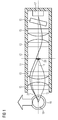
- a device has a housing 11, in which a channel 12 for guiding a beam 13 along a beam axis 14 is provided.
- a channel 12 for guiding a beam 13 along a beam axis 14 is provided on the beam axis 14 optical elements in the form of converging lenses 15, a daylight filter 16 and a photodetector 17 are arranged.
- a measuring cell 18 in the form of a cuvette containing a sample 19.
- the light of a light source is focused in the sample 19 and forms at the exit the beam 13, which is absorbed by a diaphragm 20 as a primary beam.
- the sample 19 contains particles that scatter light from the beam 13, wherein a light beam of the scattered light 21 is shown. This extends in a direction that it passes by the aperture 20 and hits the photodetector 17. Together with other rays of the scattered light, a measurement signal is generated in this way.
- the aperture 20 is mounted in a manner not shown in the housing 11.
- One possibility is, for example, in a montage, such as in FIG. 5 shown.
- the mounting direction of the diaphragm 20 is perpendicular to the plane, for example, in this.
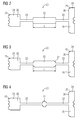
- the aperture 20 according to FIG. 2 has a diaphragm surface 22 which is connected by holding webs 23 with widened regions 24.
- the areas 24 are located at each end of the panel.
- the diaphragm surface 22 has a length L and is rectangular.
- the widened regions 24, with which the diaphragm 20 is fixed in the housing 11, have Ein 1500schrägen 25, which facilitate the threading of the aperture in the housing.
- a plurality of surface portions of the widened portions 24 serve as reference surfaces 26, which, as in FIG. 5 shown correspond with different mating surfaces (eg 32) in the housing and set in this way the position of the diaphragm 20 uniquely.
- the aperture 20 according to FIG. 3 differs from the one according to FIG. 2 only in the form of the diaphragm surface 22, which has rounded portions 27 at the corners.
- the aperture according to FIG. 4 is suitable for hiding the beam in a structure of the device according to FIG. 1 where the aperture lies in the focal point of the beam and therefore only a small aperture area is required.
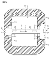
- the housing 11 can be seen in cross section.
- a diaphragm 20 is inserted through a passage opening 28, which additionally has recesses 29 for a component, not shown.
- an opening 30 is provided, in which the aperture 20 is pushed in from the side of the channel 12 from.
- the widened regions 24 of the diaphragm 20 come to lie in the passage opening 28 and the opening 30.
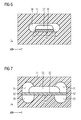
- the arrangement of the mating surfaces can be FIG. 5 in conjunction with the FIGS. 6 and 7 remove.
- the corresponding mating surfaces act, that is, in which spatial direction they define the diaphragm 20.
- the cross section of the channel 12 is according to FIG. 5 in the xy plane, wherein the x-direction corresponds to the mounting direction of the diaphragm 20.
- the z-direction is the beam axis 14 (as FIG. 1 ).
- the assembly movement in the x direction is limited by two mating surfaces 31. These lie in milling holes, which are not through go the entire wall and the hole bottom forms the mating surfaces 31. These two milling holes also form mating surfaces 32 with their elongated, vertically aligned side walls, against which the side edges of the widened region 24 come to lie.
- the passage hole is further formed by a milled slot 33 which passes through the wall and the underlying side wall forms a further mating surface 34, which serves to position the diaphragm 20 in the z-direction. Due to the mutual penetration of the elongated hole 33 and the two lateral cutouts 35, the curves of the elongated hole 33 in the region of the mating surface 34 are removed.
- the opening 30 consists of two penetrating slots 36, 37, both slots do not pass through the entire wall but intersect only in their bottom area.
- Through the slot 36 is in the central region of the long, straight surface a mating surface 38 (see. FIG. 6 ), which ensures a determination of the diaphragm 20 in the z-direction.
- the slot 37 has a straight portion of the wall, which provides as a mating surface 39 for fixing the aperture 20 in the y direction.
- the mating surfaces 32 and 39 are arranged in pairs opposite one another. This prevents movement of the diaphragm 20 in the positive and negative y-direction.
- the mating surfaces 34 and 38 have no opposite counterpart. These determine the position of the diaphragm in the z-direction, but this can move away from the respective mating surface in a positive z-direction.
- the passage opening 28 and the opening 30 can be filled with a potting compound (not shown).
Landscapes
- Physics & Mathematics (AREA)
- General Physics & Mathematics (AREA)
- Optics & Photonics (AREA)
- Health & Medical Sciences (AREA)
- Life Sciences & Earth Sciences (AREA)
- Chemical & Material Sciences (AREA)
- Analytical Chemistry (AREA)
- Biochemistry (AREA)
- General Health & Medical Sciences (AREA)
- Immunology (AREA)
- Pathology (AREA)
- Diaphragms For Cameras (AREA)
Priority Applications (1)
| Application Number | Priority Date | Filing Date | Title |
|---|---|---|---|
| EP14172737.0A EP2957896A1 (fr) | 2014-06-17 | 2014-06-17 | Dispositif optique de conduite d'un faisceau de rayons et écran destiné à être installé dans celui-ci |
Applications Claiming Priority (1)
| Application Number | Priority Date | Filing Date | Title |
|---|---|---|---|
| EP14172737.0A EP2957896A1 (fr) | 2014-06-17 | 2014-06-17 | Dispositif optique de conduite d'un faisceau de rayons et écran destiné à être installé dans celui-ci |
Publications (1)
| Publication Number | Publication Date |
|---|---|
| EP2957896A1 true EP2957896A1 (fr) | 2015-12-23 |
Family
ID=50979556
Family Applications (1)
| Application Number | Title | Priority Date | Filing Date |
|---|---|---|---|
| EP14172737.0A Ceased EP2957896A1 (fr) | 2014-06-17 | 2014-06-17 | Dispositif optique de conduite d'un faisceau de rayons et écran destiné à être installé dans celui-ci |
Country Status (1)
| Country | Link |
|---|---|
| EP (1) | EP2957896A1 (fr) |
Cited By (1)
| Publication number | Priority date | Publication date | Assignee | Title |
|---|---|---|---|---|
| DE102017112613B4 (de) * | 2017-06-08 | 2020-10-01 | Olympus Winter & Ibe Gmbh | Verfahren zum Schwärzen einer Blende, geschwärzte Blende, optisches System und Endoskop mit einer solchen Blende |
Citations (5)
| Publication number | Priority date | Publication date | Assignee | Title |
|---|---|---|---|---|
| GB688653A (en) * | 1949-08-22 | 1953-03-11 | Hans Herman Loeschcke | Improvements relating to photo-electric measuring apparatus |
| DE3608552A1 (de) | 1986-03-14 | 1987-09-17 | Bayer Ag | Nephelometer |
| DE19849597A1 (de) | 1998-10-28 | 2000-05-04 | Dade Behring Marburg Gmbh | Nephelometrische Detektionseinheit mit optischer In-Prozeß-Kontrolle |
| US6817788B1 (en) * | 2003-05-29 | 2004-11-16 | Nihon Seimitsu Sokki Co., Ltd. | Diaphragm device |
| DE102009043524A1 (de) | 2009-09-30 | 2011-03-31 | Siemens Healthcare Diagnostics Products Gmbh | Vorrichtung für die photometrische Untersuchung von Proben |
-
2014
- 2014-06-17 EP EP14172737.0A patent/EP2957896A1/fr not_active Ceased
Patent Citations (5)
| Publication number | Priority date | Publication date | Assignee | Title |
|---|---|---|---|---|
| GB688653A (en) * | 1949-08-22 | 1953-03-11 | Hans Herman Loeschcke | Improvements relating to photo-electric measuring apparatus |
| DE3608552A1 (de) | 1986-03-14 | 1987-09-17 | Bayer Ag | Nephelometer |
| DE19849597A1 (de) | 1998-10-28 | 2000-05-04 | Dade Behring Marburg Gmbh | Nephelometrische Detektionseinheit mit optischer In-Prozeß-Kontrolle |
| US6817788B1 (en) * | 2003-05-29 | 2004-11-16 | Nihon Seimitsu Sokki Co., Ltd. | Diaphragm device |
| DE102009043524A1 (de) | 2009-09-30 | 2011-03-31 | Siemens Healthcare Diagnostics Products Gmbh | Vorrichtung für die photometrische Untersuchung von Proben |
Cited By (1)
| Publication number | Priority date | Publication date | Assignee | Title |
|---|---|---|---|---|
| DE102017112613B4 (de) * | 2017-06-08 | 2020-10-01 | Olympus Winter & Ibe Gmbh | Verfahren zum Schwärzen einer Blende, geschwärzte Blende, optisches System und Endoskop mit einer solchen Blende |
Similar Documents
| Publication | Publication Date | Title |
|---|---|---|
| EP1963821B1 (fr) | Puce de mesure | |
| EP2055371B1 (fr) | Dispositif d'amenée de gaz vers un instrument d'analyse | |
| DE4310583A1 (de) | Teststreifenanalysesystem | |
| EP0488947A1 (fr) | Cellule détectrice | |
| EP2698626A2 (fr) | Récipient réactionnel | |
| EP3329284B1 (fr) | Procede de determination de fibrinogenes | |
| WO2009003714A2 (fr) | Dispositif et procédé pour réaliser des mesures statiques et dynamiques de la lumière diffusée dans des petits volumes | |
| EP2145682A1 (fr) | Elément de test destiné à l'analyse d'un analyte contenu dans un échantillon de liquide corporel, système d'analyse et procédé de commande du mouvement d'un liquide contenu dans un canal d'un élément de test | |
| EP2350676B1 (fr) | Dispositif d'analyse automatisé présentant un dispositif automatique de prélèvement par pipette et un bras de prélèvement par pipette muni d'un détecteur d'impact | |
| EP4091715A1 (fr) | Syst?me de bandelette réactive pourvu de récipients | |
| EP2957896A1 (fr) | Dispositif optique de conduite d'un faisceau de rayons et écran destiné à être installé dans celui-ci | |
| EP2711080A1 (fr) | Aiguille creuse pour pipette de prélèvement | |
| EP1881319B1 (fr) | Procédé et dispositif destinés à mesurer la diffusion de la lumière | |
| DE102013215210B3 (de) | Reaktionsgefäß, Reaktionsgefäßanordnung und Verfahren zur Analyseeiner Substanz | |
| DE4425462C2 (de) | Spektralphotometer-Zelle | |
| DE19849597A1 (de) | Nephelometrische Detektionseinheit mit optischer In-Prozeß-Kontrolle | |
| DE102014113163B3 (de) | Reaktionsgefäß, Reaktionsgefäßanordnung und Verfahren zur Analyse einer Substanz | |
| DE202014104316U1 (de) | Reaktionsgefäß und Reaktionsgefäßanordnung zur Analyse einer Substanz | |
| DE102011008788B3 (de) | Anordnung zur Durchführung einer Einzelprobenanalyse und -manipulation für die Raman-Mikrospektroskopie | |
| EP2957897A1 (fr) | Scatteromètre doté d'un carrousel pour porte-échantillons cylindriques ou anguleux et d'un arrêt de faisceau pour lumière non diffusée qui est élargie de manière à recevoir la lumière non diffusée réfractée par le porte-échantillon | |
| DE102011117320A1 (de) | Vorrichtung und Verfahren zum Nachweis von in biologischen oder chemischen Proben vorliegenden Substanzen | |
| EP2957895A1 (fr) | Système de mesure de lumière diffusée ayant un écran central pour le rayonnement primaire | |
| DE3213533A1 (de) | Infrarot-spektrometer | |
| EP2957894A1 (fr) | Système d'analyse confocal à écran diffusant | |
| DE19800479C2 (de) | Vorrichtung zum Kalibrieren und zur Kalibrierkontrolle für Photometer-Prozeßmeßtechnik |
Legal Events
| Date | Code | Title | Description |
|---|---|---|---|
| PUAI | Public reference made under article 153(3) epc to a published international application that has entered the european phase |
Free format text: ORIGINAL CODE: 0009012 |
|
| AK | Designated contracting states |
Kind code of ref document: A1 Designated state(s): AL AT BE BG CH CY CZ DE DK EE ES FI FR GB GR HR HU IE IS IT LI LT LU LV MC MK MT NL NO PL PT RO RS SE SI SK SM TR |
|
| AX | Request for extension of the european patent |
Extension state: BA ME |
|
| STAA | Information on the status of an ep patent application or granted ep patent |
Free format text: STATUS: THE APPLICATION HAS BEEN REFUSED |
|
| 18R | Application refused |
Effective date: 20160123 |