EP2957871A1 - Method of prediction of an aircraft short term flight path, computer program product, associated prediction device, guidance method, guidance system and aircraft - Google Patents
Method of prediction of an aircraft short term flight path, computer program product, associated prediction device, guidance method, guidance system and aircraft Download PDFInfo
- Publication number
- EP2957871A1 EP2957871A1 EP15170522.5A EP15170522A EP2957871A1 EP 2957871 A1 EP2957871 A1 EP 2957871A1 EP 15170522 A EP15170522 A EP 15170522A EP 2957871 A1 EP2957871 A1 EP 2957871A1
- Authority
- EP
- European Patent Office
- Prior art keywords
- aircraft
- trajectory
- prediction
- short
- date
- Prior art date
- Legal status (The legal status is an assumption and is not a legal conclusion. Google has not performed a legal analysis and makes no representation as to the accuracy of the status listed.)
- Granted
Links
Images


Classifications
-
- G—PHYSICS
- G05—CONTROLLING; REGULATING
- G05D—SYSTEMS FOR CONTROLLING OR REGULATING NON-ELECTRIC VARIABLES
- G05D1/00—Control of position, course or altitude of land, water, air, or space vehicles, e.g. automatic pilot
- G05D1/10—Simultaneous control of position or course in three dimensions
- G05D1/101—Simultaneous control of position or course in three dimensions specially adapted for aircraft
-
- G—PHYSICS
- G01—MEASURING; TESTING
- G01C—MEASURING DISTANCES, LEVELS OR BEARINGS; SURVEYING; NAVIGATION; GYROSCOPIC INSTRUMENTS; PHOTOGRAMMETRY OR VIDEOGRAMMETRY
- G01C23/00—Combined instruments indicating more than one navigational value, e.g. for aircraft; Combined measuring devices for measuring two or more variables of movement, e.g. distance, speed or acceleration
-
- G—PHYSICS
- G08—SIGNALLING
- G08G—TRAFFIC CONTROL SYSTEMS
- G08G5/00—Traffic control systems for aircraft, e.g. air-traffic control [ATC]
- G08G5/0047—Navigation or guidance aids for a single aircraft
Definitions
- the invention also relates to a computer program product comprising software instructions which, when implemented by a computer, implement such a method.
- the invention also relates to a prediction device implementing such a method.
- the invention also relates to a method for guiding an aircraft.
- the invention also relates to a guidance system implementing such a guide method.
- the invention also relates to an aircraft comprising such a device.
- the invention applies to the field of guidance aids of an aircraft, including the prediction of a short-term trajectory.
- Aircraft trajectory is understood to mean a vector comprising at least one of aircraft position, aircraft attitudes and first and second order time derivatives of said positions and attitudes. These derivatives of order 1 and 2 then correspond to translation speeds, angular velocities, accelerations and angular accelerations.
- Prediction of a short-term trajectory means the prediction on a calculation date T of all or part of the components of the vector associated with the trajectory of the aircraft at a prediction date T 'after the date of calculation T, the date of T 'prediction being within a time period of up to 30 seconds from the calculation date T of said trajectory.
- the pilot of an aircraft controls the aircraft using mainly one or more primary control members, generally a handle (or “yoke” in English) or a mini-stick (or “side-stick” in English). ) and / or one or more throttles.
- a primary control member generally a handle (or “yoke” in English) or a mini-stick (or “side-stick” in English).
- the pilot commands a change of attitude of the aircraft, or causes an increase in the thrust of one or more reactors of the aircraft, which has the effect of change the trajectory of the aircraft.
- the pilot uses his own sensations, for example the acceleration he feels during the actuation of the primary control organs or the evolution of his visual references, as well as his flight experience to anticipate the trajectory to come and to rectify this trajectory to bring the aircraft to the desired trajectory.
- the pilot generally has no explicit indication of the short-term consequence, on the flight path of the aircraft, of an action on the primary control members.
- US 8,086,362 B2 describes a method of predicting the trajectory of an aircraft from instructions from a pilot of the aircraft, and display of the predicted trajectory.
- the value of the setpoints for calculating the trajectory is considered constant and equal to the value of the setpoint at a given calculation date.
- An object of the invention is therefore to improve the prediction of the trajectory of the aircraft, in particular the prediction of the short-term trajectory.
- the subject of the invention is a method of the aforementioned type, in which the prediction step furthermore comprises the calculation, from the control signal, of an estimate, between the calculation date and a date of calculation. subsequent prediction of at least one time derivative of at least one predicted component, the or each estimated time derivative depending on the prediction date and the deflection of each primary control member.
- the calculation, from the control signal, of an estimate of the variations over time of a time derivative of the or each predicted component provides a more reliable prediction of the short-term trajectory of the aircraft.
- the invention also relates to a computer program product comprising software instructions which, when implemented by a computer, implement the method as defined above.
- the invention also relates to an aircraft comprising at least one control member and a prediction device as defined above for predicting the short-term trajectory of the aircraft from a command applied by a user to the each control member.
- the aircraft further comprises a servo device for controlling the short-term trajectory of the aircraft relative to the predicted short-term trajectory.
- an aircraft 1 comprises a guidance system 2, primary control members 3 and a plurality of sensors 4.
- the guidance system 2 shown on the figure 1 is adapted to enslave the trajectory of an aircraft 1 relative to a predetermined short-term trajectory.
- the guidance system 2 is embarked on board the aircraft 1.
- the guidance system 2 comprises a device 5 for predicting the short-term trajectory of the aircraft 1, also called a predicted short-term trajectory.
- the guidance system 2 also comprises a device 6 for controlling the trajectory of the aircraft 1 on the short-term trajectory predicted by the prediction device 5.
- the primary control members 3 comprise one or more sleeves or mini-sleeves 8 and one or more thrust control members 10 and optionally the drag of the aircraft 1. Thereafter, the term “sleeve” will designate indifferently a sleeve or a mini-sleeve.
- Each primary control member 3 comprises an acquisition device 11 able to convert a command applied by a user to the primary control member 3 into a control signal representative of the command applied.
- a command is for example a variation control of a component of the trajectory of the aircraft 1.
- Such a system is commonly called "flyby wire”.
- the primary control members 3 are adapted to convert an action exerted by the user on the primary control members 3 into a mechanical action on an actuator of the aircraft 1.
- an actuator is for example an aerodynamic control surface.
- Such a system is commonly called “mechanical flight control”.
- the aircraft 1 then comprises conversion systems (not shown) suitable for converting a command applied by a user to the primary control member 3 into a control signal representative of the command applied.
- the handle 8 is adapted to allow a user to control the attitudes of the aircraft 1, for example by controlling a roll rate and a load factor of the aircraft 1.
- roll rate is meant the angular velocity associated with the roll angle, i.e., the time derivative of the roll angle, the roll angle being defined later.
- Load factor means the ratio between the apparent weight of the aircraft 1 and the standard of its actual weight, projected on a vertical reference axis z 1 defined later.
- the handle is adapted to be operated in transverse movements, longitudinal movements or any combination of transverse and longitudinal movements.
- the handle 8 is adapted to allow a user to control the roll rate by transverse movements of the handle 8.
- the handle 8 is adapted to allow a user to control the load factor by longitudinal movements. of the handle 8.
- control member 10 is adapted to allow the user to set a power via, for example, a thrust level, a motor speed, a fuel flow, a propeller pitch or rotor.
- the thrust control member 10 comprises one or more throttles.
- the sensors 4 are each adapted to provide at least one item relating to the configuration of the aircraft 1 or to the physical parameters of the air in the vicinity of the aircraft 1, for example the temperature of the air, its pressure, or its speed relative to the aircraft 1.
- the sensors 4 comprise sensors capable of providing information relating to the position of the aircraft 1, to the attitudes of the aircraft 1, to the first and second order derivatives with respect to the time of the position and the attitudes of the aircraft. the aircraft 1.
- attitudes is meant in the sense of the invention, the oriented angles taken between predetermined axes of the aircraft 1, said aircraft axes, and their projection on reference planes. Among the attitudes, one distinguishes the angle of roll, pitch angle and heading, known per se and recalled below, with reference to the figure 5 .
- the reference planes are determined from three reference axes.
- the aircraft axes and the reference axes are concurrent at a predetermined point A of the aircraft 1, for example close to the center of gravity of the aircraft 1.
- the reference axes are the axes of the local terrestrial reference frame and comprise a vertical reference axis z 0 , a longitudinal reference axis x 0 and a transverse reference axis y 0 , forming a direct orthonormal basis (x 0 , y 0 , z 0 ) called "reference base”.
- the vertical reference axis z 0 is an axis oriented in the descending direction of the local gravitational field and passing through the predetermined point A of the aircraft 1.
- the longitudinal reference axis x 0 is an axis oriented in a predetermined direction for example towards the magnetic or geographical North, and orthogonal to the vertical reference axis z 0 .
- the transverse reference axis y 0 completes z 0 and x 0 to form the "reference base".
- the vertical reference axes z 0 and longitudinal x 0 form a vertical reference plane.
- the transverse reference axes y 0 and longitudinal x 0 form a horizontal reference plane.
- the aircraft axes comprise a longitudinal aircraft axis x 1 , a vertical aircraft axis z 1 and a transverse aircraft axis y 1 , forming a direct orthonormal base (x 1 , y 1 , z 1 ) called "aircraft base”.
- the longitudinal aircraft axis x 1 is a forward-facing axis of the aircraft 1, passing through the predetermined point A and belonging to a plane of symmetry of the aircraft 1.
- the plane of symmetry of the aircraft 1 is generally related to the geometric definition of the cell of the aircraft 1.
- the transverse aircraft axis y 1 is the axis perpendicular to the plane of symmetry and oriented to the right of the aircraft 1, that is to say the right of an observer aboard the aircraft 1 and looking towards the front of the aircraft 1.
- the vertical aircraft axis z 1 complete y 1 and x 1 to form the "aircraft base".
- the angle ⁇ between the transverse aircraft axis y 1 and the horizontal reference plane is the roll angle.
- the angle ⁇ between the longitudinal aircraft axis x 1 and the reference plane horizontal is the pitch angle.
- the angle ⁇ between the longitudinal aircraft axis x 1 and the vertical reference plane is the heading.
- ⁇ , ⁇ and ⁇ are generally called the Euler angles allowing to pass from the aircraft base to the reference base.
- the sensors 4 also include sensors capable of providing information relating to the position of mechanical elements of the aircraft 1, for example the position of a rudder, the configuration and the state of the engine or engines.
- the sensors 4 furthermore comprise sensors capable of making measurements of the relative air speed of the aircraft 1, such as measurements of the true airspeed (TAS), the conventional speed CAS (of the English “Calibrated Airspeed” or “Computed Airspeed”) Mach speed or altitudes.
- TAS true airspeed
- CAS conventional speed CAS
- Mach speed or altitudes Mach speed or altitudes.
- sensors are, for example, ADU (Air Data Unit) systems.
- the sensors 4 of the aircraft 1 are for example integrated in an AHRS system (of the English “Attitude and Heading Reference System”) or IRS (of the English “Inertial Reference System”).
- AHRS AHRS system
- IRS Integrated Reference System
- these sensors are suitable for measuring the speeds in the reference base as well as the geographical position of the aircraft 1.
- the sensors 4 comprise GPS sensors and / or a radio altimeter.
- the prediction device 5 comprises a memory 12.
- the prediction device 5 also comprises a computer 14 for calculating the short-term trajectory of the aircraft 1 from the action of a user on all or part of the primary control members 3, as well as from data stored in the memory 12 and / or from the or each sensor 4.
- the prediction device 5 further comprises a display 16 adapted to display, advantageously intended for the user, the short-term trajectory predicted by the computer 14.
- the display is distinct from the guidance system 2 or the control device. prediction 5.
- the memory 12 is adapted to store a plurality of data relating to the aircraft 1, for example data relating to the performance of the aircraft 1, or data relating to one or more configurations of the aircraft 1 that are authorized, still called "flight domain".
- the flight range comprises the minimum and maximum allowed roll and pitch angles (defined below) for the aircraft 1 at a given instant.
- the flight range depends, for example, on the flight phase of the aircraft 1, or on the altitude of the aircraft 1.
- the computer 14 is adapted to calculate, on a calculation date T, a prediction of the trajectory of the aircraft 1 on a prediction date T ', after the calculation date T.
- the computer 14 comprises a plurality of prediction modules 22.
- the computer 14 comprises three prediction modules 22.
- the computer 14 comprises a single prediction module 22.
- the display 16 is for example a display or head-up display (HUD or HMD), or any screen of the cockpit (for example a PFD, of the English "Primary Flight Display”).
- HUD head-up display
- PFD Portable Flight Display
- the prediction modules 22 are able to communicate with each other, for example via a shared bus.
- Each prediction module 22 is able to calculate, on the calculation date T, from the control signal or from a control signal transform as defined later, an estimation of the value, on the prediction date T ' subsequent, all or part of the components of the trajectory of the aircraft 1.
- At least one prediction module 22 is able to calculate, from the control signal or from a control signal transform, an estimate of the value, at the later prediction date T ', of at least one time derivative.
- each prediction module 22 is able to calculate, from the control signal, the variation, between the calculation date T and the prediction date T ', of the roll angle, and / or of the slope and / or the air speed module (TAS or CAS or Mach) and / or the ground speed module of the aircraft 1.
- ground speed is meant the projection of the vector-speed of the aircraft 1 on the plane (x 0 , y 0 ) formed by the axes x 0 and y 0 .
- Slope means the angle between the reference horizontal plane and the ground speed vector of the aircraft 1.
- a first prediction module 22 is adapted to calculate an estimate of the variation of the roll angle.
- a second prediction module 22 is adapted to calculate an estimate of the variation of the slope.
- a third prediction module 22 is adapted to calculate an estimate of the variation of the longitudinal velocity.
- each prediction module 22 is able to first calculate a first estimate, called the "preliminary estimate", of the variation over time of the corresponding component of the trajectory of the aircraft 1.
- Each prediction module 22 is then able to calculate, from all or part of the preliminary estimates, a corrected estimate of the corresponding component of the trajectory of the aircraft 1.
- each prediction module 22 is able to convert the control signal into a setpoint, and then to calculate an estimate of the variation of the corresponding component of the trajectory of the aircraft 1 from the setpoint.
- each prediction module 22 is able to convert the control signal into a load factor setpoint and / or roll rate and / or longitudinal acceleration, and then to calculate an estimate of the variation of said component of the control signal. trajectory of the aircraft 1 from said one or more instructions.
- the prediction module 22 is adapted to calculate, from the control signal, an estimate of the variation between the calculation date T and the prediction date T. ', longitudinal acceleration and load factor and roll rate.
- the single prediction module 22 is further adapted to calculate, from the control signal, the variation, between the calculation date T and the prediction date T ', of the longitudinal speed, and / or of the slope and / or the roll angle, respectively from the predicted variation of the longitudinal acceleration and / or the load factor and / or the roll rate.
- each prediction module 22 comprises a memory 24, a processor 26 and a transceiver 28, the memory 24 and the processor 26 forming an information processing unit 30.
- the memory 24 is suitable for storing a software 32 for reading data, a conversion software 34, a processing software 36, an estimation software 38, a software 40 for receiving an estimate, and a software for correction 42.
- the processor 26 is able to load and execute each of the software programs 32, 34, 36, 38, 40, 42.
- the transceiver 28 is capable of transmitting estimates calculated by the corresponding prediction module 22 to another prediction module 22 and / or to the display 16.
- the transceiver 28 is further adapted to receive estimates calculated by other prediction modules 22, and to receive data from the memory 12 and the sensors 4.
- the reading software 32 is adapted to read the data stored in the memory 12 and the data transmitted by the sensors 4, as well as to read the control signal transmitted by each of the primary control members 3.
- the conversion software 34 is suitable for converting each control signal into a setpoint, such as a longitudinal acceleration setpoint, or a load factor setpoint, or a roll rate setpoint, from read data. by the reading software 32 in the memory 12 and / or from the sensors 4.
- the processing software 36 is able to calculate, from the control signal converted by the conversion software 34, an estimate of the variation over time, from the calculation date T to the prediction date T ', the magnitude corresponding to the control signal.
- the processing software 36 is also able to calculate the transformation of the control signal via a predetermined transformation.
- a transformation is intended to provide a signal representative of an estimate in at least one later date T * at the calculation date T, such as at dates before and after the prediction date T ', of the future evolution of the control signal from the value of the control signal in at least one date prior to or equal to the calculation date T.
- a filter is applied to the control signal.
- the filter is a predetermined transfer function linear filter H.
- each sample of the control signal transform is a function of one or more samples of the control signal and one or more preceding samples of the control signal transform.
- the transfer function H is the transfer function of a filter having a positive phase in a predetermined frequency band.
- the transfer function filter H has a positive phase in the frequency band between 0 Hz and 20 Hz, preferably between 0 Hz and 10 Hz, more preferably between 0 Hz and 5 Hz.
- the transfer function H is for example the transfer function of a high-pass filter.
- H p BOY WUT 1 + K ⁇ p
- G, K are the coefficients of the transfer function H.
- the value of all or part of the coefficients G, K of the transfer function H varies as a function of the data provided by the sensors 4.
- the different values allowed for the coefficients G, K are stored in the memory 12.
- the processing software 36 When executed, the processing software 36 is adapted to modify the values of the coefficients G, K according to the data provided by the sensors 4 and read by the reading software 32.
- the processing software 36 is further adapted to calculate a time integral of a signal dependent on the control signal, and to add the value of the calculated integral to the current value of the corresponding magnitude.
- the transmission software 38 is able to send an estimate from the prediction module 22 corresponding to another prediction module 22.
- the software 38 is able to issue a preliminary estimate to the other prediction modules 22.
- the reception software 40 of a given prediction module 22 is able to receive an estimate from another prediction module 22.
- the correction software 42 is adapted to correct the estimate calculated by the processing software 36 of the corresponding prediction module 22, on receipt of an estimate from another prediction module 22.
- a correction notably reflects the variation over time of the angles between the aircraft axes and the reference axes, and therefore the variation over time of the projection of the velocity vectors of the aircraft in the reference base.
- Such a correction also reflects the variation over time of the modules of the speeds of the aircraft 1. For example, such a correction takes into account the relationship between the vertical speed and the slope, and the relationship between the vertical speed and the ground speed.
- Such a correction also reflects, for example, the relationship between the roll angle, the ground speed and a turning radius, the turning radius being a notion known to those skilled in the art.
- the correction software 42 is also adapted to correct the calculated estimate in case of variation of the measured value by one or more predetermined sensors 4.
- the user actuates, during a first step 100, the handle 8 or the thrust control member 10.
- the acquisition device 11 converts the manual control of the user into a control signal.
- the computer 14 calculates at the calculation date T, and from the control signal, a prediction of the short-term trajectory of the aircraft 1 at the subsequent prediction date T '. In particular, the computer 14 calculates a prediction of the longitudinal speed, the slope and the roll angle of the aircraft 1 at the prediction date T '.
- step 105 has a plurality of sub-steps.
- the reading software 32 of each prediction module 22 reads the control signal delivered by the primary control member 3 associated with the prediction module 22.
- the reading software 32 reads the data provided by the sensors 4.
- the reading software 32 then reads in the memory 12 the predetermined coefficients G, K which correspond to the data received since the 4.
- the processing software 34 converts the control signal into a setpoint of the parameter associated with the control signal, that is to say for example a longitudinal acceleration setpoint, or a charge factor setpoint or a setpoint. roll rate.
- the reading software 32 reads from the memory 12 the predetermined coefficients of the transfer function H, corresponding to the data received from the sensors 4 during the step 110.
- the processing software 36 applies, to the setpoint, the predetermined filter, whose coefficients are the coefficients read in the memory 12 by the reading software 32, to calculate an estimate of the variation of the component of the trajectory corresponding to the prediction module 22 among the longitudinal acceleration, the load factor and the roll rate.
- the estimate issuing software 38 transmits the estimate calculated in step 110 to the other prediction modules 22.
- the processing software 36 corrects the previously calculated estimate.
- the processing software 36 calculates the time integral of the estimate of the component of the trajectory corresponding to the prediction module 22 to obtain a longitudinal speed variation. or slope or roll angle.
- the processing software 36 will have calculated the variation of the slope of the aircraft 1 between the date calculation T and the prediction date T '.
- the processing software 36 calculates the estimate of the corresponding component of the trajectory of the aircraft 1 at the prediction date T 'by adding the predicted variation of said component to the value current, at the calculation date T, of the said component.
- the current value of the component corresponding to the prediction module 22 is supplied by the sensors 4 and read by the reading software 32.
- the processing software 36 corrects the value of the predicted variation so that the corresponding predicted component is no longer outside the flight range.
- step 140 the display 16 displays all or part of the predicted short-term trajectory calculated by the computer 14 at the end of step 105.
- the servo-control device 6 controls the aircraft 1 to control its trajectory relative to the predicted trajectory calculated by the computer at the end of step 105.
- the predicted trajectory then forms a guidance instruction intended to be transmitted to the device enslavement 6.
- the predicted trajectory is fixed, that is to say that it is no longer modified, since it forms a guidance instruction.
- the handle 8 comprises a longitudinal neutral zone and a transverse neutral zone.
- the longitudinal neutral zone, or the transverse neutral zone represents a predefined range of deflection of the handle 8 around its equilibrium point in a longitudinal direction, transverse respectively, such that a range of 5 ° centered on the point of equilibrium , that is to say around the position of the handle 8 when no force is exerted on the handle 8.
- the control device 6 controls the aircraft 1 to control the slope with respect to the predicted slope, calculated by the computer at the end of step 105.
- the device servocontrol 6 commands the aircraft 1 to control the roll angle relative to the predicted roll angle, calculated by the computer at the end of step 105.
- the thrust control member 10 comprises a neutral zone.
- the neutral zone represents a predefined range of travel of the control member 10 around a predetermined position, such as a range of 5 ° centered on the predetermined position. If the control member 10 is in the neutral zone, then during the next step 150, the control device 6 controls the aircraft 1 to slave the longitudinal speed with respect to the predicted longitudinal speed, calculated by the calculator at the end of step 105.
- the prediction device 5 again calculates an estimate of the short-term trajectory of the aircraft 1, during the step 105.
- the integration substep 130 precedes the estimation substep 115. Therefore, during the estimation step 115, the processing software 36 applies the filter H to the integral relative to the substep. at the time of the control signal. At the end of the estimation sub-step 115, the processing software 36 will then have calculated the variation of the trajectory of the aircraft 1.
- the integration sub-step 130 precedes the substep 125.
- the calculation, from the control signal, of an estimate of the variations over time of time derivatives of predicted components of the trajectory of the aircraft 1 provides a steering aid and improves the safety of the flight.
- the calculation of an estimate of the variation over time of at least one component among the roll rate, the load factor and the longitudinal acceleration of the aircraft 1 provides an even more reliable prediction in the short run. term, the trajectory being in fact calculated from the predicted variations and not from a constant setpoint as is done in the state of the art.
- control signal for example by a filter whose transfer function has a phase greater than or equal to zero in a frequency band of interest, outputs a signal in advance of phase by report to the control signal. This makes it possible to anticipate the variations of the control signal and leads to a better prediction of the short-term trajectory.
- the transfer function H of the filter varies as a function of time, in particular as a function of parameters depending on the type of the aircraft 1 and / or on the quantities measured by the sensors 4 of the aircraft 1, makes it possible to improve the prediction of the trajectory by adapting the filter to the flight conditions of the aircraft 1.
Abstract
L'invention a pour objet un procédé de prédiction d'une trajectoire court terme d'un aéronef, la trajectoire de l'aéronef étant associée à chaque instant temporel à un vecteur comportant au moins une composante parmi une position de l'aéronef, des attitudes de l'aéronef et les dérivées temporelles d'ordre 1 et 2 desdites position et attitudes, la trajectoire court terme étant la trajectoire de l'aéronef pour une période temporelle allant jusqu'à 30 secondes à compter d'une date de calcul de ladite trajectoire, le procédé comportant : - une étape (100) d'acquisition d'un signal de commande représentatif d'un débattement d'un organe primaire de commande de l'aéronef ; - une étape (105) de prédiction à une date de prédiction ultérieure d'au moins une composante de la trajectoire court terme de l'aéronef, l'étape de prédiction étant effectuée à la date de calcul.The subject of the invention is a method for predicting a short-term trajectory of an aircraft, the trajectory of the aircraft being associated at each time instant with a vector comprising at least one component from a position of the aircraft, aircraft attitudes and time derivatives of orders 1 and 2 of said positions and attitudes, the short-term trajectory being the trajectory of the aircraft for a time period of up to 30 seconds from a date of calculation of said trajectory, the method comprising: a step (100) for acquiring a control signal representing a movement of a primary control member of the aircraft; a step (105) of prediction at a later prediction date of at least one component of the short-term trajectory of the aircraft, the prediction step being carried out at the calculation date.
Description
La présente invention concerne un procédé de prédiction d'une trajectoire court terme d'un aéronef, la trajectoire de l'aéronef étant associée à chaque instant temporel à un vecteur comportant au moins une composante parmi une position de l'aéronef, des attitudes de l'aéronef et les dérivées temporelles d'ordre 1 et 2 desdites position et attitudes, la trajectoire court terme étant la trajectoire de l'aéronef pour une période temporelle allant jusqu'à 30 secondes à compter d'une date de calcul de ladite trajectoire, le procédé comportant :
- une étape d'acquisition d'un signal de commande représentatif d'un débattement d'un organe primaire de commande de l'aéronef ;
- une étape de prédiction à une date de prédiction ultérieure d'au moins une composante de la trajectoire court terme de l'aéronef, l'étape de prédiction étant effectuée à la date de calcul.
- a step of acquiring a control signal representative of a movement of a primary control member of the aircraft;
- a prediction step at a later prediction date of at least one component of the short-term trajectory of the aircraft, the prediction step being performed at the calculation date.
L'invention concerne également un produit programme d'ordinateur comportant des instructions logicielles qui, lorsqu'elles sont mises en oeuvre par un ordinateur, mettent en oeuvre un tel procédé.The invention also relates to a computer program product comprising software instructions which, when implemented by a computer, implement such a method.
L'invention concerne également un dispositif de prédiction mettant en oeuvre un tel procédé.The invention also relates to a prediction device implementing such a method.
L'invention concerne également un procédé de guidage d'un aéronef.The invention also relates to a method for guiding an aircraft.
L'invention concerne également un système de guidage mettant en oeuvre un tel procédé de guidage.The invention also relates to a guidance system implementing such a guide method.
L'invention concerne également un aéronef comportant un tel dispositif.The invention also relates to an aircraft comprising such a device.
L'invention s'applique au domaine de l'aide au guidage d'un aéronef, notamment à la prédiction d'une trajectoire court terme.The invention applies to the field of guidance aids of an aircraft, including the prediction of a short-term trajectory.
Par « trajectoire de l'aéronef », on entend un vecteur comportant au moins une composante parmi une position de l'aéronef, des attitudes de l'aéronef et les dérivées temporelles d'ordre 1 et 2 desdites position et attitudes. Ces dérivées d'ordre 1 et 2 correspondent alors aux vitesses de translation, aux vitesses angulaires, aux accélérations et aux accélérations angulaires."Aircraft trajectory" is understood to mean a vector comprising at least one of aircraft position, aircraft attitudes and first and second order time derivatives of said positions and attitudes. These derivatives of
Par « prédiction d'une trajectoire court terme », on entend la prédiction à une date de calcul T, de tout ou partie des composantes du vecteur associé à la trajectoire de l'aéronef à une date de prédiction T' postérieure à la date de calcul T, la date de prédiction T' étant comprise dans une période temporelle allant jusqu'à 30 secondes à compter de la date de calcul T de ladite trajectoire."Prediction of a short-term trajectory" means the prediction on a calculation date T of all or part of the components of the vector associated with the trajectory of the aircraft at a prediction date T 'after the date of calculation T, the date of T 'prediction being within a time period of up to 30 seconds from the calculation date T of said trajectory.
De façon classique, le pilote d'un aéronef commande l'appareil en utilisant principalement un ou plusieurs organes primaires de commande, généralement un manche (ou « yoke » en anglais) ou un mini-manche (ou « side-stick » en anglais) et/ou une ou plusieurs manettes des gaz. Via l'actionnement du ou de chaque organe primaire de commande, le pilote commande un changement d'attitude de l'aéronef, ou provoque une augmentation de la poussée d'un ou des réacteurs de l'appareil, ce qui a pour effet de modifier la trajectoire de l'aéronef.Conventionally, the pilot of an aircraft controls the aircraft using mainly one or more primary control members, generally a handle (or "yoke" in English) or a mini-stick (or "side-stick" in English). ) and / or one or more throttles. Via the actuation of the or each primary control member, the pilot commands a change of attitude of the aircraft, or causes an increase in the thrust of one or more reactors of the aircraft, which has the effect of change the trajectory of the aircraft.
Généralement, le pilote utilise ses propres sensations, par exemple l'accélération qu'il ressent lors de l'actionnement des organes primaires de commande ou encore l'évolution de ses références visuelles, ainsi que son expérience du vol pour anticiper la trajectoire à venir et pour rectifier cette trajectoire jusqu'à amener l'aéronef vers la trajectoire souhaitée.Generally, the pilot uses his own sensations, for example the acceleration he feels during the actuation of the primary control organs or the evolution of his visual references, as well as his flight experience to anticipate the trajectory to come and to rectify this trajectory to bring the aircraft to the desired trajectory.
Toutefois, le pilote n'a généralement aucune indication explicite concernant la conséquence à court terme, sur la trajectoire de l'aéronef, d'une action sur les organes primaires de commande.However, the pilot generally has no explicit indication of the short-term consequence, on the flight path of the aircraft, of an action on the primary control members.
Durant la mise en oeuvre de ce procédé, la valeur des consignes pour le calcul de la trajectoire est considérée comme constante et égale à la valeur de la consigne à une date de calcul donnée.During the implementation of this method, the value of the setpoints for calculating the trajectory is considered constant and equal to the value of the setpoint at a given calculation date.
Lorsque la manoeuvre n'est pas réalisée à consigne constante, par exemple à roulis constant, la trajectoire prédite diffère parfois de manière importante de la trajectoire réelle à venir.When the maneuver is not performed at constant setpoint, for example constant rolling, the predicted trajectory sometimes differs significantly from the actual trajectory to come.
Un but de l'invention est donc d'améliorer la prédiction de la trajectoire de l'aéronef, notamment la prédiction de la trajectoire court terme.An object of the invention is therefore to improve the prediction of the trajectory of the aircraft, in particular the prediction of the short-term trajectory.
A cet effet, l'invention a pour objet un procédé du type précité, dans lequel l'étape de prédiction comporte en outre le calcul, à partir du signal de commande, d'une estimation, entre la date de calcul et une date de prédiction ultérieure, d'au moins une dérivée temporelle d'au moins une composante prédite, la ou chaque dérivée temporelle estimée dépendant de la date de prédiction ultérieure et du débattement de chaque organe primaire de commande.For this purpose, the subject of the invention is a method of the aforementioned type, in which the prediction step furthermore comprises the calculation, from the control signal, of an estimate, between the calculation date and a date of calculation. subsequent prediction of at least one time derivative of at least one predicted component, the or each estimated time derivative depending on the prediction date and the deflection of each primary control member.
En effet, le calcul, à partir du signal de commande, d'une estimation des variations au cours du temps d'une dérivée temporelle de la ou chaque composante prédite fournit une prédiction plus fiable de la trajectoire court terme de l'aéronef.Indeed, the calculation, from the control signal, of an estimate of the variations over time of a time derivative of the or each predicted component provides a more reliable prediction of the short-term trajectory of the aircraft.
Suivant d'autres aspects avantageux de l'invention, le procédé comporte une ou plusieurs des caractéristiques suivantes, prise(s) isolément ou suivant toute combinaison techniquement possible :
- l'étape de prédiction comporte le calcul d'au moins une composante de la trajectoire court terme de l'aéronef à partir de l'estimation calculée de la ou chaque dérivée temporelle correspondante ;
- l'étape de prédiction comporte en outre le calcul d'une estimation de la variation entre la date de calcul et la date de prédiction, d'au moins une composante parmi l'angle de roulis, la vitesse longitudinale et la vitesse verticale de l'aéronef, et/ou d'au moins une grandeur additionnelle relative à l'aéronef telle qu'un rayon de virage, une vitesse relative à l'air, ou une pente de l'aéronef ;
- l'étape de prédiction comprend la transformation d'un premier signal dépendant du signal de commande en un deuxième signal représentatif d'une estimation de la valeur du premier signal en au moins une date postérieure à la date de calcul, à partir de la valeur du premier signal en au moins une date antérieure ou égale à la date de calcul ;
- la transformation du signal dépendant du signal de commande est l'application audit signal d'un filtre présentant une fonction de transfert dont la phase est supérieure ou égale à zéro dans une bande prédéterminée de fréquences ;
- la fonction de transfert du filtre varie en fonction du temps, de préférence en fonction du type de l'aéronef et/ou de grandeurs dépendant du temps mesurées par au moins un capteur de l'aéronef ;
- l'étape de prédiction comporte la modification de l'estimation de la variation d'au moins une composante de la trajectoire court terme de l'aéronef et/ou d'au moins une grandeur additionnelle, telle qu'un rayon de virage, une vitesse relative à l'air, ou une pente de l'aéronef, en fonction d'au moins une estimation de la variation d'une autre composante de la trajectoire court terme de l'aéronef et/ou d'une autre grandeur additionnelle, telle qu'un rayon de virage, une vitesse relative à l'air, ou une pente de l'aéronef.
- the prediction step comprises calculating at least one component of the short-term trajectory of the aircraft from the calculated estimate of the or each corresponding time derivative;
- the prediction step further comprises calculating an estimate of the variation between the calculation date and the prediction date, of at least one component of the roll angle, the longitudinal velocity and the vertical velocity of the aircraft, and / or at least one additional quantity relating to the aircraft such as a turning radius, a speed relative to the air, or a slope of the aircraft;
- the prediction step comprises transforming a first signal dependent on the control signal into a second signal representative of an estimate of the value of the first signal in at least one date after the calculation date, from the value the first signal in at least one date prior to or equal to the date of calculation;
- the transformation of the signal depending on the control signal is the application to said signal of a filter having a transfer function whose phase is greater than or equal to zero in a predetermined frequency band;
- the filter transfer function varies as a function of time, preferably depending on the type of the aircraft and / or time dependent quantities measured by at least one sensor of the aircraft;
- the prediction step comprises modifying the estimate of the variation of at least one component of the short-term trajectory of the aircraft and / or of at least one additional quantity, such as a turning radius, a relative air speed, or a slope of the aircraft, based on at least one estimate of the variation of another component of the short-term trajectory of the aircraft and / or of another additional magnitude, such as a turning radius, a relative air speed, or a slope of the aircraft.
L'invention a également pour objet un produit programme d'ordinateur comportant des instructions logicielles qui, lorsqu'elles sont mises en oeuvre par un ordinateur, mettent en oeuvre le procédé tel que défini ci-dessus.The invention also relates to a computer program product comprising software instructions which, when implemented by a computer, implement the method as defined above.
L'invention a également pour objet un dispositif de prédiction d'une trajectoire court terme d'un aéronef, la trajectoire de l'aéronef étant associée à chaque instant temporel à un vecteur comportant au moins une composante parmi une position de l'aéronef, des attitudes de l'aéronef et les dérivées temporelles d'ordre 1 et 2 desdites position et attitudes, la trajectoire court terme étant la trajectoire de l'aéronef pour une période temporelle allant jusqu'à 30 secondes à compter d'une date de calcul de ladite trajectoire, le dispositif comportant :
- des moyens d'acquisition d'un signal de commande représentatif d'une commande appliquée par un utilisateur à un organe de commande de l'aéronef ;
- au moins un module de prédiction, à la date de calcul d'au moins une composante de la trajectoire court terme de l'aéronef ;
- means for acquiring a control signal representative of a command applied by a user to a control member of the aircraft;
- at least one prediction module, on the date of calculation of at least one component of the short-term trajectory of the aircraft;
L'invention a également pour objet un procédé de guidage d'un aéronef comportant les étapes suivantes :
- la prédiction d'une trajectoire court terme suivant le procédé tel que défini ci-dessus ;
- l'asservissement d'au moins une composante de la trajectoire de l'aéronef par rapport à la composante correspondante de la trajectoire prédite.
- predicting a short-term trajectory according to the method as defined above;
- the servocontrol of at least one component of the trajectory of the aircraft relative to the corresponding component of the predicted trajectory.
Suivant d'autres aspects avantageux de l'invention, le procédé de guidage comporte une ou plusieurs des caractéristiques suivantes, prise(s) isolément ou suivant toute combinaison techniquement possible :
- la ou chaque composante prédite de la trajectoire n'est plus modifiée durant l'étape d'asservissement et forme alors une consigne destinée à être transmise à un dispositif d'asservissement de la trajectoire de l'aéronef ;
- le ou chaque organe primaire de commande est associé à au moins une composante de la trajectoire, le ou chaque organe primaire de commande présente une zone neutre, la zone neutre représentant une plage prédéfinie de débattement de l'organe primaire de commande autour d'une position prédéterminée de l'organe primaire de commande, et, lorsqu'un organe primaire de commande est positionné en position neutre suivant une ou plusieurs directions, la ou les composantes de la trajectoire de l'aéronef associées auxdites directions sont asservies par rapport à la composante prédite correspondante de la trajectoire court terme.
- the or each predicted component of the trajectory is no longer modified during the servo-control step and then forms a setpoint intended to be transmitted to a device for controlling the trajectory of the aircraft;
- the or each primary control member is associated with at least one component of the trajectory, the or each primary control member has a neutral zone, the neutral zone representing a predefined range of movement of the primary control member around a predetermined position of the primary control member, and, when a primary control member is positioned in a neutral position along one or more directions, the component or components of the trajectory of the aircraft associated with said directions are slaved with respect to the corresponding predicted component of the short-term trajectory.
L'invention a également pour objet un système de guidage d'un aéronef, comportant :
- un dispositif de prédiction tel que défini ci-dessus, propre à prédire une trajectoire court terme de l'aéronef ;
- un dispositif d'asservissement propre à asservir la trajectoire de l'aéronef par rapport à la trajectoire court terme prédite.
- a prediction device as defined above, capable of predicting a short-term trajectory of the aircraft;
- a servo device adapted to enslave the trajectory of the aircraft relative to the predicted short-term trajectory.
L'invention a également pour objet un aéronef comportant au moins un organe de commande et un dispositif de prédiction tel que défini ci-dessus pour prédire la trajectoire court terme de l'aéronef à partir d'une commande appliquée par un utilisateur au ou à chaque organe de commande.The invention also relates to an aircraft comprising at least one control member and a prediction device as defined above for predicting the short-term trajectory of the aircraft from a command applied by a user to the each control member.
Suivant un autre aspect avantageux de l'invention, l'aéronef comporte en outre un dispositif d'asservissement pour asservir la trajectoire court terme de l'aéronef par rapport à la trajectoire court terme prédite.According to another advantageous aspect of the invention, the aircraft further comprises a servo device for controlling the short-term trajectory of the aircraft relative to the predicted short-term trajectory.
L'invention sera mieux comprise à l'aide de la description qui va suivre, donnée uniquement à titre d'exemple non limitatif, et faite en se référant aux dessins annexés sur lesquels :
- la
figure 1 est une représentation schématique d'un système de guidage d'un aéronef selon l'invention, le système de guidage comportant trois modules de prédiction de la trajectoire court terme ; - la
figure 2 est une représentation schématique d'une des modules de prédiction de lafigure 1 ; - la
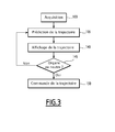
figure 3 est un organigramme d'un procédé de guidage de l'aéronef, mis en oeuvre par le système de lafigure 1 ; - la
figure 4 est un détail d'une étape du procédé de lafigure 3 ; et - la
figure 5 est une représentation schématique des projections des vecteurs d'une base liée à l'aéronef dans une base de référence.
- the
figure 1 is a schematic representation of a guidance system of an aircraft according to the invention, the guidance system comprising three modules for predicting the short-term trajectory; - the
figure 2 is a schematic representation of one of the prediction modules of thefigure 1 ; - the
figure 3 is a flowchart of a method for guiding the aircraft, implemented by the system of thefigure 1 ; - the
figure 4 is a detail of a step in the process of thefigure 3 ; and - the
figure 5 is a schematic representation of the vector projections of a base linked to the aircraft in a reference base.
Sur la
Le système de guidage 2 représenté sur la
De préférence, le système de guidage 2 est embarqué à bord de l'aéronef 1.Preferably, the
Le système de guidage 2 comporte un dispositif 5 de prédiction de la trajectoire court terme de l'aéronef 1, encore appelée trajectoire court terme prédite. Le système de guidage 2 comporte également un dispositif 6 d'asservissement de la trajectoire de l'aéronef 1 sur la trajectoire court terme prédite par le dispositif de prédiction 5.The
Les organes primaires de commande 3 comportent un ou plusieurs manches ou mini-manches 8 et un ou plusieurs organes 10 de commande de la poussée et optionnellement de la trainée de l'aéronef 1. Par la suite, le terme « manche » désignera indifféremment un manche ou un mini-manche.The
Chaque organe primaire de commande 3 comporte un dispositif d'acquisition 11 propre à convertir une commande appliquée par un utilisateur sur l'organe primaire de commande 3 en un signal de commande représentatif de la commande appliquée. Une telle commande est par exemple une commande de variation d'une composante de la trajectoire de l'aéronef 1. Un tel système est communément appelé « commandes de vol électriques » (en anglais « fly by wire »).Each
En variante, les organes primaires de commande 3 sont adaptés pour convertir une action exercée par l'utilisateur sur les organes primaires de commande 3 en une action mécanique sur un actionneur de l'aéronef 1. Un tel actionneur est par exemple une gouverne aérodynamique. Un tel système est communément appelé « commande de vol mécanique ». L'aéronef 1 comporte alors des systèmes de conversion (non représentés) propres à convertir une commande appliquée par un utilisateur sur l'organe primaire de commande 3 en un signal de commande représentatif de la commande appliquée.In a variant, the
Le manche 8 est adapté pour permettre à un utilisateur de piloter les attitudes de l'aéronef 1, par exemple en commandant un taux de roulis et un facteur de charge de l'aéronef 1.The
Par « taux de roulis », on entend la vitesse angulaire associée à l'angle de roulis, c'est-à-dire la dérivée temporelle de l'angle de roulis, l'angle de roulis étant défini ultérieurement.By "roll rate" is meant the angular velocity associated with the roll angle, i.e., the time derivative of the roll angle, the roll angle being defined later.
Par « facteur de charge », on entend le rapport entre le poids apparent de le l'aéronef 1 et la norme de son poids réel, projeté sur un axe de référence vertical z1 défini ultérieurement."Load factor" means the ratio between the apparent weight of the aircraft 1 and the standard of its actual weight, projected on a vertical reference axis z 1 defined later.
De façon classique, le manche est adapté pour être actionné selon des mouvements transversaux, des mouvements longitudinaux ou toute combinaison de mouvements transversaux et longitudinaux.Conventionally, the handle is adapted to be operated in transverse movements, longitudinal movements or any combination of transverse and longitudinal movements.
Plus précisément, le manche 8 est adapté pour permettre à un utilisateur de commander le taux de roulis par des mouvements transversaux du manche 8. En outre, le manche 8 est adapté pour permettre à un utilisateur de commander le facteur de charge par des mouvements longitudinaux du manche 8.More specifically, the
De façon classique, l'organe de commande 10 est adapté pour permettre à l'utilisateur de fixer une puissance via, par exemple, un niveau de poussée, un régime moteur, un débit de combustible, un pas d'hélice ou de rotor. Par exemple, l'organe 10 de commande de la poussée comporte une ou plusieurs manettes des gaz.Conventionally, the
Les capteurs 4 sont chacun propres à fournir au moins une donnée relative à la configuration de l'aéronef 1 ou aux paramètres physiques de l'air à proximité de l'aéronef 1, par exemple la température de l'air, sa pression, ou encore sa vitesse par rapport à l'aéronef 1.The
Avantageusement, les capteurs 4 comprennent des capteurs propres à fournir une information relative à la position de l'aéronef 1, aux attitudes de l'aéronef 1, aux dérivées d'ordre 1 et 2 par rapport au temps de la position et des attitudes de l'aéronef 1.Advantageously, the
Par « attitudes », on entend au sens de l'invention, les angles orientés pris entre des axes prédéterminés de l'aéronef 1, dits axes aéronef, et leur projection sur des plans de référence. Parmi les attitudes, on distingue l'angle de roulis, l'angle de tangage et le cap, connus en soi et rappelés ci-après, en référence à la
Les plans de référence sont déterminés à partir de trois axes de référence.The reference planes are determined from three reference axes.
Les axes aéronef et les axes de référence sont concourants en un point prédéterminé A de l'aéronef 1, par exemple proche du centre de gravité de l'aéronef 1.The aircraft axes and the reference axes are concurrent at a predetermined point A of the aircraft 1, for example close to the center of gravity of the aircraft 1.
Les axes de référence sont les axes du référentiel terrestre local et comprennent un axe de référence vertical z0, un axe de référence longitudinal x0 et un axe de référence transversal y0, formant une base orthonormée directe (x0,y0,z0) dite « base de référence ».The reference axes are the axes of the local terrestrial reference frame and comprise a vertical reference axis z 0 , a longitudinal reference axis x 0 and a transverse reference axis y 0 , forming a direct orthonormal basis (x 0 , y 0 , z 0 ) called "reference base".
L'axe de référence vertical z0 est un axe orienté suivant la direction descendante du champ de pesanteur local et passant par le point prédéterminé A de l'aéronef 1. L'axe de référence longitudinal x0 est un axe orienté dans une direction prédéterminée, par exemple vers le Nord magnétique ou géographique, et orthogonal à l'axe de référence vertical z0. L'axe de référence transversal y0 complète z0 et x0 pour former la « base de référence ».The vertical reference axis z 0 is an axis oriented in the descending direction of the local gravitational field and passing through the predetermined point A of the aircraft 1. The longitudinal reference axis x 0 is an axis oriented in a predetermined direction for example towards the magnetic or geographical North, and orthogonal to the vertical reference axis z 0 . The transverse reference axis y 0 completes z 0 and x 0 to form the "reference base".
Les axes de référence vertical z0 et longitudinal x0 forment un plan de référence vertical. Les axes de référence transversal y0 et longitudinal x0 forment un plan de référence horizontal.The vertical reference axes z 0 and longitudinal x 0 form a vertical reference plane. The transverse reference axes y 0 and longitudinal x 0 form a horizontal reference plane.
Les axes aéronef comprennent un axe aéronef longitudinal x1, un axe aéronef vertical z1 et un axe aéronef transversal y1, formant une base orthonormée directe (x1,y1,z1) dite « base aéronef ».The aircraft axes comprise a longitudinal aircraft axis x 1 , a vertical aircraft axis z 1 and a transverse aircraft axis y 1 , forming a direct orthonormal base (x 1 , y 1 , z 1 ) called "aircraft base".
L'axe aéronef longitudinal x1 est un axe orienté vers l'avant de l'aéronef 1, passant par le point prédéterminé A et appartenant à un plan de symétrie de l'aéronef 1. Le plan de symétrie de l'aéronef 1 est généralement lié à la définition géométrique de la cellule de l'aéronef 1. L'axe aéronef transversal y1 est l'axe perpendiculaire au plan de symétrie et orienté vers la droite de l'aéronef 1, c'est-à-dire la droite d'un observateur à bord de l'aéronef 1 et regardant vers l'avant de l'aéronef 1. L'axe aéronef vertical z1 complète y1 et x1 pour former la « base aéronef ».The longitudinal aircraft axis x 1 is a forward-facing axis of the aircraft 1, passing through the predetermined point A and belonging to a plane of symmetry of the aircraft 1. The plane of symmetry of the aircraft 1 is generally related to the geometric definition of the cell of the aircraft 1. The transverse aircraft axis y 1 is the axis perpendicular to the plane of symmetry and oriented to the right of the aircraft 1, that is to say the right of an observer aboard the aircraft 1 and looking towards the front of the aircraft 1. The vertical aircraft axis z 1 complete y 1 and x 1 to form the "aircraft base".
L'angle Φ entre l'axe aéronef transversal y1 et le plan de référence horizontal est l'angle de roulis. L'angle θ entre l'axe aéronef longitudinal x1 et le plan de référence horizontal est l'angle de tangage. L'angle ψ entre l'axe aéronef longitudinal x1 et le plan de référence vertical est le cap. Φ, θ et ψ sont généralement appelés les angles d'Euler permettant de passer de la base aéronef à la base de référence.The angle Φ between the transverse aircraft axis y 1 and the horizontal reference plane is the roll angle. The angle θ between the longitudinal aircraft axis x 1 and the reference plane horizontal is the pitch angle. The angle ψ between the longitudinal aircraft axis x 1 and the vertical reference plane is the heading. Φ, θ and ψ are generally called the Euler angles allowing to pass from the aircraft base to the reference base.
Avantageusement, les capteurs 4 comprennent également des capteurs propres à fournir une information relative à la position d'éléments mécaniques de l'aéronef 1, par exemple la position d'une gouverne, la configuration et l'état du ou des moteurs.Advantageously, the
Avantageusement, les capteurs 4 comprennent en outre des capteurs propres à réaliser des mesures de la vitesse relative à l'air de l'aéronef 1, telles que des mesures de la vitesse vraie TAS (de l'anglais « True Airspeed »), la vitesse conventionnelle CAS (de l'anglais « Calibrated Airspeed » ou « Computed Airspeed ») la vitesse Mach ou encore les altitudes. De tels capteurs sont par exemple des systèmes ADU (de l'anglais « Air Data Unit »).Advantageously, the
Les capteurs 4 de l'aéronef 1 sont par exemple intégrés dans un système AHRS (de l'anglais « Attitude and Heading Référence System ») ou IRS (de l'anglais « Inertial Référence System »). Avantageusement, ces capteurs sont propres à mesurer les vitesses dans la base de référence ainsi que la position géographique de l'aéronef 1.The
Avantageusement, les capteurs 4 comportent des capteurs GPS et/ou un radioaltimètre.Advantageously, the
Le dispositif de prédiction 5 comporte une mémoire 12. Le dispositif de prédiction 5 comporte également un calculateur 14 pour calculer la trajectoire court terme de l'aéronef 1 à partir de l'action d'un utilisateur sur tout ou partie des organes primaires de commande 3, ainsi qu'à partir de données stockées dans la mémoire 12 et/ou en provenance du ou de chaque capteur 4.The
Le dispositif de prédiction 5 comporte en outre un afficheur 16 propre à afficher, avantageusement à destination de l'utilisateur, la trajectoire court terme prédite par le calculateur 14. En variante, l'afficheur est distinct du système de guidage 2 ou du dispositif de prédiction 5.The
La mémoire 12 est adaptée pour stocker une pluralité de données relatives à l'aéronef 1, par exemple des données relatives aux performances de l'aéronef 1, ou encore des données relatives à une ou plusieurs configurations de l'aéronef 1 qui sont autorisées, encore appelées « domaine de vol ». Par exemple, le domaine de vol comprend les angles de roulis et de tangage (définis ci-après) minimaux et maximaux autorisés pour l'aéronef 1 à un instant donné. Le domaine de vol dépend par exemple de la phase de vol de l'aéronef 1, ou encore de l'altitude de l'aéronef 1.The
Le calculateur 14 est adapté pour calculer, à une date de calcul T, une prédiction de la trajectoire de l'aéronef 1 à une date de prédiction T', postérieure à la date de calcul T.The
Le calculateur 14 comporte une pluralité de modules de prédiction 22. Par exemple, le calculateur 14 comporte trois modules de prédiction 22.The
En variante, le calculateur 14 comporte un unique module de prédiction 22.In a variant, the
L'afficheur 16 est par exemple un afficheur ou viseur tête haute (HUD ou HMD, de l'anglais « Head-Up Display » ou « Helmet Mounted Display »), ou tout écran du cockpit (par exemple un PFD, de l'anglais « Primary Flight Display »).The
Les modules de prédiction 22 sont propres à communiquer entre eux, par exemple via un bus partagé.The
Chaque module de prédiction 22 est propre à calculer, à la date de calcul T, à partir du signal de commande ou d'une transformée du signal de commande telle que définie ultérieurement, une estimation de la valeur, à la date de prédiction T' ultérieure, de toute ou partie des composantes de la trajectoire de l'aéronef 1.Each
Notamment, au moins un module de prédiction 22 est propre à calculer, à partir du signal de commande ou d'une transformée du signal de commande, une estimation de la valeur, à la date de prédiction T' ultérieure, d'au moins une dérivée temporelle.In particular, at least one
De préférence, chaque module de prédiction 22 est propre à calculer, à partir du signal de commande, la variation, entre la date de calcul T et la date de prédiction T', de l'angle de roulis, et/ou de la pente et/ou du module de la vitesse air (TAS ou CAS ou Mach) et/ou le module de la vitesse sol (« ground speed » en anglais) de l'aéronef 1. Par « vitesse sol », on entend la projection du vecteur-vitesse de l'aéronef 1 sur le plan (x0, y0) formé par les axes x0 et y0.Preferably, each
Par « pente », on entend l'angle entre le plan horizontal de référence et le vecteur-vitesse sol de l'aéronef 1."Slope" means the angle between the reference horizontal plane and the ground speed vector of the aircraft 1.
Dans l'exemple de la
Un deuxième module de prédiction 22 est adapté pour calculer une estimation de la variation de la pente.A
Un troisième module de prédiction 22 est adapté pour calculer une estimation de la variation de la vitesse longitudinale.A
De façon optionnelle, chaque module de prédiction 22 est propre à d'abord calculer une première estimation, dite « estimation préliminaire », de la variation au cours du temps de la composante correspondante de la trajectoire de l'aéronef 1.Optionally, each
Chaque module de prédiction 22 est alors propre à calculer, à partir de tout ou partie des estimations préliminaires, une estimation corrigée de la composante correspondante de la trajectoire de l'aéronef 1.Each
Avantageusement, chaque module de prédiction 22 est propre à convertir le signal de commande en une consigne, puis à calculer une estimation de la variation de la composante correspondante de la trajectoire de l'aéronef 1 à partir de la consigne.Advantageously, each
Avantageusement, chaque module de prédiction 22 est propre à convertir le signal de commande en une consigne de facteur de charge et/ou de taux de roulis et/ou d'accélération longitudinale, puis à calculer une estimation de la variation de ladite composante de la trajectoire de l'aéronef 1 à partir de ladite ou desdites consignes.Advantageously, each
Selon la variante où le calculateur 14 comporte un unique module de prédiction 22, le module de prédiction 22 est adapté pour calculer, à partir du signal de commande, une estimation de la variation, entre la date de calcul T et la date de prédiction T', de l'accélération longitudinale et du facteur de charge et du taux de roulis.According to the variant where the
L'unique module de prédiction 22 est en outre adapté pour calculer, à partir du signal de commande, la variation, entre la date de calcul T et la date de prédiction T', de la vitesse longitudinale, et/ou de la pente et/ou de l'angle de roulis, respectivement à partir de la variation prédite de l'accélération longitudinale et/ou du facteur de charge et/ou du taux de roulis.The
Dans l'exemple de réalisation décrit, chaque module de prédiction 22 comporte une mémoire 24, un processeur 26 et un émetteur-récepteur 28, la mémoire 24 et le processeur 26 formant une unité 30 de traitement d'informations.In the embodiment described, each
La mémoire 24 est propre à stocker un logiciel 32 de lecture de données, un logiciel de conversion 34, un logiciel de traitement 36, un logiciel 38 d'émission d'estimation, un logiciel 40 de réception d'estimation, et un logiciel de correction 42.The
Le processeur 26 est propre à charger et à exécuter chacun des logiciels 32, 34, 36, 38, 40, 42.The
L'émetteur-récepteur 28 est propre à émettre des estimations calculées par le module de prédiction 22 correspondant vers un autre module de prédiction 22 et/ou vers l'afficheur 16.The
L'émetteur-récepteur 28 est en outre propre à recevoir des estimations calculées par d'autres modules de prédiction 22, et à recevoir des données en provenance de la mémoire 12 et des capteurs 4.The
Le logiciel de lecture 32 est adapté pour lire les données stockées dans la mémoire 12 et les données émises par les capteurs 4, ainsi que pour lire le signal de commande émis par chacun des organes primaires de commande 3.The
Le logiciel de conversion 34 est propre à convertir chaque signal de commande en une consigne, telle qu'une consigne d'accélération longitudinale, ou en une consigne de facteur de charge, ou en une consigne de taux de roulis, à partir de données lues par le logiciel de lecture 32 dans la mémoire 12 et/ou en provenance des capteurs 4.The
Le logiciel de traitement 36 est propre à calculer, à partir du signal de commande converti par le logiciel de conversion 34, une estimation de la variation au cours du temps, depuis la date de calcul T jusqu'à la date de prédiction T', de la grandeur correspondant au signal de commande.The
Le logiciel de traitement 36 est également propre à calculer la transformée du signal de commande via une transformation prédéterminée. Une telle transformation a pour but de fournir un signal représentatif d'une estimation en au moins une date postérieure T* à la date de calcul T, tel qu'en des dates antérieure et postérieure à la date de prédiction T', de l'évolution future du signal de commande à partir de la valeur du signal de commande en au moins une date antérieure ou égale à la date de calcul T.The
Par exemple, un filtre est appliqué au signal de commande.For example, a filter is applied to the control signal.
Par exemple, dans le cas de signaux continus, le filtre est un filtre linéaire de fonction de transfert H prédéterminée.For example, in the case of continuous signals, the filter is a predetermined transfer function linear filter H.
Par exemple, dans le cas de signaux discrets, chaque échantillon de la transformée du signal de commande est fonction d'un ou de plusieurs échantillons du signal de commande et d'un ou de plusieurs échantillons précédents de la transformée du signal de commande.For example, in the case of discrete signals, each sample of the control signal transform is a function of one or more samples of the control signal and one or more preceding samples of the control signal transform.
Avantageusement, la fonction de transfert H est la fonction de transfert d'un filtre présentant une phase positive dans une bande de fréquences prédéterminée. Avantageusement, le filtre de fonction de transfert H présente une phase positive dans la bande de fréquences comprise entre 0 Hz et 20 Hz, de préférence comprise entre 0 Hz et 10 Hz, de préférence encore comprise entre 0 Hz et 5 Hz.Advantageously, the transfer function H is the transfer function of a filter having a positive phase in a predetermined frequency band. Advantageously, the transfer function filter H has a positive phase in the frequency band between 0 Hz and 20 Hz, preferably between 0 Hz and 10 Hz, more preferably between 0 Hz and 5 Hz.
La fonction de transfert H est par exemple la fonction de transfert d'un filtre passe-haut.The transfer function H is for example the transfer function of a high-pass filter.
Par exemple, dans le cas de signaux continus, dans le domaine de Laplace, une expression simple d'un filtre passe-haut H s'écrit : 
La valeur de tout ou partie des coefficients G, K de la fonction de transfert H varie en fonction des données fournies par les capteurs 4. Les différentes valeurs autorisées pour les coefficients G, K sont stockées dans la mémoire 12.The value of all or part of the coefficients G, K of the transfer function H varies as a function of the data provided by the
Par exemple, pour la prédiction du taux de roulis ou du facteur de charge, la fonction de transfert H s'écrit : ![]()
![]()
Dans le cas de signaux discrets, la relation entre les échantillons en entrée et en sortie du filtre se déduit classiquement des expressions précédentes de la fonction de transfert H.In the case of discrete signals, the relationship between the input and output samples of the filter is conventionally derived from previous expressions of the transfer function H.
Lorsqu'il est exécuté, le logiciel de traitement 36 est adapté pour modifier les valeurs des coefficients G, K en fonction des données fournies par les capteurs 4 et lues par le logiciel de lecture 32.When executed, the
Le logiciel de traitement 36 est en outre adapté pour calculer une intégrale par rapport au temps d'un signal dépendant du signal de commande, et pour ajouter la valeur de l'intégrale calculée à la valeur courante de la grandeur correspondante.The
Le logiciel d'émission 38 est propre à émettre une estimation issue du module de prédiction 22 correspondant vers un autre module de prédiction 22. De préférence, le logiciel 38 est propre à émettre une estimation préliminaire vers les autres modules de prédiction 22.The
Le logiciel de réception 40 d'un module de prédiction 22 donné est propre à recevoir une estimation en provenance d'un autre module de prédiction 22.The
Le logiciel de correction 42 est adapté pour corriger l'estimation calculée par le logiciel de traitement 36 du module de prédiction 22 correspondant, en cas de réception d'une estimation provenant d'un autre module de prédiction 22. Une telle correction traduit notamment la variation au cours du temps des angles entre les axes aéronef et les axes de référence, et donc la variation au cours du temps de la projection des vecteurs-vitesses de l'aéronef dans la base de référence. Une telle correction traduit également la variation au cours du temps des modules des vitesses de l'aéronef 1. Par exemple, une telle correction tient compte de la relation entre la vitesse verticale et la pente, et de la relation entre la vitesse verticale et la vitesse sol. Une telle correction traduit également par exemple la relation entre l'angle de roulis, la vitesse sol et un rayon de virage, le rayon de virage étant une notion connue de l'homme du métier.The
Le logiciel de correction 42 est également adapté pour corriger l'estimation calculée en cas de variation de la valeur mesurée par un ou plusieurs capteurs 4 prédéterminés.The
Le fonctionnement du système de guidage 2 va maintenant être décrit, en référence aux
Durant la phase de vol de l'aéronef 1, l'utilisateur actionne, au cours d'une première étape 100, le manche 8 ou l'organe 10 de commande de la poussée.During the flight phase of the aircraft 1, the user actuates, during a
Le dispositif d'acquisition 11 convertit la commande manuelle de l'utilisateur en un signal de commande.The
Au cours d'une étape suivante 105, le calculateur 14 calcule à la date de calcul T, et à partir du signal de commande, une prédiction de la trajectoire court terme de l'aéronef 1 à la date de prédiction ultérieure T'. Notamment, le calculateur 14 calcule une prédiction de la vitesse longitudinale, de la pente et de l'angle de roulis de l'aéronef 1 à la date de prédiction T'.During a
Comme cela apparaît sur la
Au cours d'une sous-étape 110, le logiciel de lecture 32 de chaque module de prédiction 22 lit le signal de commande délivré par l'organe primaire de commande 3 associé au module de prédiction 22.During a sub-step 110, the
En outre, au cours de la sous-étape 110, le logiciel de lecture 32 lit les données fournies par les capteurs 4. Le logiciel de lecture 32 lit ensuite dans la mémoire 12 les coefficients G, K prédéterminés qui correspondent aux données reçues depuis les capteurs 4. Puis le logiciel de traitement 34 convertit le signal de commande en une consigne du paramètre associé au signal de commande, c'est-à-dire par exemple une consigne d'accélération longitudinale, ou une consigne de facteur de charge ou de taux de roulis.In addition, during the sub-step 110, the
Au cours d'une sous-étape suivante 115, le logiciel de lecture 32 lit dans la mémoire 12 les coefficients prédéterminés de la fonction de transfert H, correspondant aux données reçues depuis les capteurs 4 au cours de l'étape 110.During a
Ensuite, le logiciel de traitement 36 applique, à la consigne, le filtre prédéterminé, dont les coefficients sont les coefficients lus dans la mémoire 12 par le logiciel de lecture 32, pour calculer une estimation de la variation de la composante de la trajectoire correspondant au module de prédiction 22 parmi l'accélération longitudinale, le facteur de charge et le taux de roulis.Then, the
Au cours d'une sous-étape suivante 120, le logiciel 38 d'émission d'estimation émet l'estimation calculée au cours de l'étape 110 à destination des autres modules de prédiction 22.During a
Au cours d'une sous-étape suivante 125, et si le logiciel 40 de réception d'estimation a reçu une estimation provenant d'un autre module de prédiction 22, le logiciel de traitement 36 corrige l'estimation calculée précédemment.During a
Au cours d'une sous-étape suivante 130 d'intégration, le logiciel de traitement 36 calcule l'intégrale par rapport au temps de l'estimation de la composante de la trajectoire correspondant au module de prédiction 22 pour obtenir une variation de vitesse longitudinale ou de pente ou d'angle de roulis.During a
Par exemple, pour le module de prédiction 22 propre à calculer la variation de la pente, à l'issue de la sous-étape 130, le logiciel de traitement 36 aura calculé la variation de la pente de l'aéronef 1 entre de la date de calcul T et la date de prédiction T'.For example, for the
Au cours d'une sous-étape suivante 135, le logiciel de traitement 36 calcule l'estimation de la composante correspondante de la trajectoire de l'aéronef 1 à la date de prédiction T' en additionnant la variation prédite de ladite composante à la valeur courante, à la date de calcul T, de la dite composante. La valeur courante de la composante correspondant au module de prédiction 22 est fournie par les capteurs 4 et lue par le logiciel de lecture 32.During a following
Avantageusement, si la composante prédite est en dehors du domaine de vol, le logiciel de traitement 36 corrige la valeur de la variation prédite pour que la composante prédite correspondante ne soit plus en dehors du domaine de vol.Advantageously, if the predicted component is outside the flight range, the
Au cours d'une étape suivante 140, l'afficheur 16 affiche toute ou partie de la trajectoire court terme prédite calculée par le calculateur 14 à l'issue de l'étape 105.During a
Si, à l'issue de l'étape d'affichage 140, l'utilisateur place, lors d'une étape 145, les organes primaires de commande 3 dans une position neutre prédéterminée, alors, au cours d'une étape suivante 150, le dispositif d'asservissement 6 commande l'aéronef 1 pour asservir sa trajectoire par rapport à la trajectoire prédite calculée par le calculateur à l'issue de l'étape 105. La trajectoire prédite forme alors une consigne de guidage destinée à être transmise au dispositif d'asservissement 6.If, at the end of the
Avantageusement, la trajectoire prédite est figée, c'est-à-dire qu'elle n'est plus modifiée, dès lors qu'elle forme une consigne de guidage.Advantageously, the predicted trajectory is fixed, that is to say that it is no longer modified, since it forms a guidance instruction.
En variante, le manche 8 comporte une zone neutre longitudinale et une zone neutre transversale. La zone neutre longitudinale, respectivement la zone neutre transversale, représente une plage prédéfinie de débattement du manche 8 autour de son point d'équilibre suivant une direction longitudinale, respectivement transversale, telle qu'une plage de 5° centrée sur le point d'équilibre, c'est-à-dire autour de la position du manche 8 lorsqu'aucun effort n'est exercé sur le manche 8. Si le manche 8 est dans la zone neutre longitudinale, alors au cours de l'étape suivante 150, le dispositif d'asservissement 6 commande l'aéronef 1 pour asservir la pente par rapport à la pente prédite, calculée par le calculateur à l'issue de l'étape 105. Si le manche 8 est dans la zone neutre transversale, alors au cours de l'étape suivante 150, le dispositif d'asservissement 6 commande l'aéronef 1 pour asservir l'angle de roulis par rapport à l'angle de roulis prédit, calculé par le calculateur à l'issue de l'étape 105.In a variant, the
En variante, l'organe 10 de commande de la poussée comporte une zone neutre. La zone neutre représente une plage prédéfinie de débattement de l'organe de commande 10 autour d'une position prédéterminée, telle qu'une plage de 5° centrée sur la position prédéterminée. Si l'organe de commande 10 est dans la zone neutre, alors au cours de l'étape suivante 150, le dispositif d'asservissement 6 commande l'aéronef 1 pour asservir la vitesse longitudinale par rapport à la vitesse longitudinale prédite, calculée par le calculateur à l'issue de l'étape 105.In a variant, the
Sinon, le dispositif de prédiction 5 calcule de nouveau une estimation de la trajectoire court terme de l'aéronef 1, lors de l'étape 105.Otherwise, the
En variante, la sous-étape d'intégration 130 précède la sous-étape d'estimation 115. Par conséquent, au cours de l'étape d'estimation 115, le logiciel de traitement 36 applique le filtre H à l'intégrale par rapport au temps du signal de commande. A l'issue de la sous-étape d'estimation 115, le logiciel de traitement 36 aura alors calculé la variation de la trajectoire de l'aéronef 1.Alternatively, the
En variante encore, la sous-étape d'intégration 130 précède la sous-étape 125.In another variant, the
Ainsi, le calcul, à partir du signal de commande, d'une estimation des variations au cours du temps des dérivées temporelles de composantes prédites de la trajectoire de l'aéronef 1 fournit une aide au pilotage et améliore la sécurité du vol.Thus, the calculation, from the control signal, of an estimate of the variations over time of time derivatives of predicted components of the trajectory of the aircraft 1 provides a steering aid and improves the safety of the flight.
En outre, le calcul d'une estimation de la variation au cours du temps d'au moins une composante parmi le taux de roulis, le facteur de charge et l'accélération longitudinale de l'aéronef 1 fournit une prédiction encore plus fiable à court terme, la trajectoire étant en effet calculée à partir des variations prédites et non à partir d'une consigne constante comme cela est fait dans l'état de la technique.In addition, the calculation of an estimate of the variation over time of at least one component among the roll rate, the load factor and the longitudinal acceleration of the aircraft 1 provides an even more reliable prediction in the short run. term, the trajectory being in fact calculated from the predicted variations and not from a constant setpoint as is done in the state of the art.
En outre, le recours à une transformation du signal de commande, par exemple par un filtre dont la fonction de transfert présente une phase supérieure ou égale à zéro dans une bande de fréquence d'intérêt, délivre en sortie un signal en avance de phase par rapport au signal de commande. Ceci permet d'anticiper les variations du signal de commande et conduit à une meilleure prédiction de la trajectoire court terme.In addition, the use of a transformation of the control signal, for example by a filter whose transfer function has a phase greater than or equal to zero in a frequency band of interest, outputs a signal in advance of phase by report to the control signal. This makes it possible to anticipate the variations of the control signal and leads to a better prediction of the short-term trajectory.
En outre, le fait que la fonction de transfert H du filtre varie en fonction du temps, notamment en fonction de paramètres dépendant du type de l'aéronef 1 et/ou de grandeurs mesurées par les capteurs 4 de l'aéronef 1, permet d'améliorer la prédiction de la trajectoire en adaptant le filtre aux conditions de vol de l'aéronef 1.In addition, the fact that the transfer function H of the filter varies as a function of time, in particular as a function of parameters depending on the type of the aircraft 1 and / or on the quantities measured by the
Claims (15)
caractérisé en ce que l'étape de prédiction (105) comporte en outre le calcul (115), à partir du signal de commande, d'une estimation, entre la date de calcul (T) et une date de prédiction (T') ultérieure, d'au moins une dérivée temporelle d'au moins une composante prédite, la ou chaque dérivée temporelle estimée dépendant de la date de prédiction ultérieure (T') et du débattement de chaque organe primaire de commande (3, 8, 10).
characterized in that the step of predicting (105) further comprises calculating (115), from the control signal, an estimate, between the calculation date (T) and a prediction date (T ') subsequent, at least one time derivative of at least one predicted component, the or each estimated time derivative depending on the subsequent prediction date (T ') and the travel of each primary control member (3, 8, 10) .
caractérisé en ce que le ou chaque module de prédiction (22) est adapté en outre pour calculer, à partir du signal de commande, une estimation, entre la date de calcul (T) et une date de prédiction (T') ultérieure, d'au moins une dérivée temporelle de la ou chaque composante prédite, la ou chaque dérivée temporelle estimée dépendant de la date de prédiction ultérieure (T').
characterized in that the or each prediction module (22) is further adapted to calculate, from the control signal, an estimate, between the calculation date (T) and a subsequent prediction date (T '), d at least one time derivative of the or each predicted component, the or each estimated time derivative depending on the subsequent prediction date (T ').
en ce que, lorsqu'un organe primaire de commande (3, 8, 10) est positionné en position neutre suivant une ou plusieurs directions, la ou les composantes de la trajectoire de l'aéronef (1) associées auxdites directions sont asservies par rapport à la composante prédite correspondante de la trajectoire court terme.Method according to Claim 10 or 11, characterized in that the or each primary control element (3, 8, 10) is associated with at least one component of the path, in that the or each primary control element (3, 8, 10) has a neutral zone, the neutral zone representing a predefined range of movement of the primary control member (3, 8, 10) around a predetermined position of the primary control member (3, 8, 10), and
in that , when a primary control member (3, 8, 10) is positioned in a neutral position in one or more directions, the component or components of the flight path of the aircraft (1) associated with said directions are slaved relative to one another. to the corresponding predicted component of the short-term trajectory.
Applications Claiming Priority (1)
| Application Number | Priority Date | Filing Date | Title |
|---|---|---|---|
| FR1401357A FR3022354B1 (en) | 2014-06-16 | 2014-06-16 | METHOD OF PREDICTING A SHORT-TERM TRACK OF AN AIRCRAFT, COMPUTER PROGRAM PRODUCT, PREDICTION AVAILABLE, GUIDING METHOD, GUIDE SYSTEM AND AIRCRAFT |
Publications (2)
| Publication Number | Publication Date |
|---|---|
| EP2957871A1 true EP2957871A1 (en) | 2015-12-23 |
| EP2957871B1 EP2957871B1 (en) | 2017-05-03 |
Family
ID=51894085
Family Applications (1)
| Application Number | Title | Priority Date | Filing Date |
|---|---|---|---|
| EP15170522.5A Active EP2957871B1 (en) | 2014-06-16 | 2015-06-03 | Method of prediction of an aircraft short term flight path, computer program product, associated prediction device, guidance method, guidance system and aircraft |
Country Status (4)
| Country | Link |
|---|---|
| US (1) | US9824594B2 (en) |
| EP (1) | EP2957871B1 (en) |
| CA (1) | CA2893734C (en) |
| FR (1) | FR3022354B1 (en) |
Families Citing this family (10)
| Publication number | Priority date | Publication date | Assignee | Title |
|---|---|---|---|---|
| EP3118578B1 (en) * | 2015-07-14 | 2018-10-03 | The Boeing Company | Method and system for autonomous generation of shortest lateral paths for unmanned aerial systems |
| KR101700535B1 (en) * | 2015-11-10 | 2017-01-26 | 한국항공우주연구원 | Unmanned Aerial Vehicle |
| US10228692B2 (en) | 2017-03-27 | 2019-03-12 | Gulfstream Aerospace Corporation | Aircraft flight envelope protection and recovery autopilot |
| US10693578B1 (en) * | 2017-08-02 | 2020-06-23 | Rockwell Collins, Inc. | Predictive radio tuning systems and methods for aircraft |
| WO2019099534A1 (en) | 2017-11-14 | 2019-05-23 | Gulfstream Aerospace Corporation | Conversion between calibrated airspeed and true airspeed in trajectory modeling |
| US11511879B2 (en) | 2017-11-14 | 2022-11-29 | Gulfstream Aerospace Corporation | Performance capability determination for aircraft |
| CN109191919B (en) * | 2018-08-01 | 2020-12-04 | 清华大学 | Four-dimensional track speed adjusting method and device based on required arrival time limit |
| CN110057353B (en) * | 2019-03-20 | 2023-03-14 | 西安电子科技大学 | Method for interrupting track association based on communication signal assistance |
| US11391218B2 (en) * | 2019-03-22 | 2022-07-19 | Pratt & Whitney Canada Corp. | Method and system for setting power of an aircraft engine |
| CN117075515B (en) * | 2023-09-05 | 2024-04-16 | 江苏芯安集成电路设计有限公司 | Singlechip control system for adjusting flight attitude based on visual analysis |
Citations (4)
| Publication number | Priority date | Publication date | Assignee | Title |
|---|---|---|---|---|
| US5920321A (en) * | 1996-09-30 | 1999-07-06 | Rockwell International Corporation | Flight management system with 3-dimensional flight path display |
| US20080161982A1 (en) * | 2006-12-21 | 2008-07-03 | Thales | Method for improving route and 4d prediction calculations by fms for atc tactical instructions |
| US20110196549A1 (en) * | 2010-02-11 | 2011-08-11 | The Boeing Company | Vertical Situation Awareness System for Aircraft |
| US8086362B2 (en) | 2007-08-22 | 2011-12-27 | Airbus Operations Sas | Method and device for aiding the piloting of an aircraft |
Family Cites Families (5)
| Publication number | Priority date | Publication date | Assignee | Title |
|---|---|---|---|---|
| US5722620A (en) * | 1995-05-15 | 1998-03-03 | The Boeing Company | Aircraft pitch-axis stability and command augmentation |
| EP1409959A2 (en) * | 1999-12-22 | 2004-04-21 | Honeywell International Inc. | Method, apparatus and computer program product for estimating airplane attitude with reduced sensor set |
| US6922631B1 (en) * | 2000-10-06 | 2005-07-26 | Honeywell International Inc. | System and method for textually displaying an original flight plan and a modified flight plan simultaneously |
| US6522958B1 (en) * | 2000-10-06 | 2003-02-18 | Honeywell International Inc. | Logic method and apparatus for textually displaying an original flight plan and a modified flight plan simultaneously |
| FR2945622B1 (en) * | 2009-05-15 | 2012-04-27 | Thales Sa | METHOD FOR SHORT TERM JOINING A RADAR GUIDED FLIGHT PLAN OF AN AIRCRAFT |
-
2014
- 2014-06-16 FR FR1401357A patent/FR3022354B1/en active Active
-
2015
- 2015-06-03 EP EP15170522.5A patent/EP2957871B1/en active Active
- 2015-06-04 CA CA2893734A patent/CA2893734C/en active Active
- 2015-06-15 US US14/739,303 patent/US9824594B2/en active Active
Patent Citations (4)
| Publication number | Priority date | Publication date | Assignee | Title |
|---|---|---|---|---|
| US5920321A (en) * | 1996-09-30 | 1999-07-06 | Rockwell International Corporation | Flight management system with 3-dimensional flight path display |
| US20080161982A1 (en) * | 2006-12-21 | 2008-07-03 | Thales | Method for improving route and 4d prediction calculations by fms for atc tactical instructions |
| US8086362B2 (en) | 2007-08-22 | 2011-12-27 | Airbus Operations Sas | Method and device for aiding the piloting of an aircraft |
| US20110196549A1 (en) * | 2010-02-11 | 2011-08-11 | The Boeing Company | Vertical Situation Awareness System for Aircraft |
Also Published As
| Publication number | Publication date |
|---|---|
| CA2893734A1 (en) | 2015-12-16 |
| CA2893734C (en) | 2022-10-04 |
| US9824594B2 (en) | 2017-11-21 |
| US20150364046A1 (en) | 2015-12-17 |
| EP2957871B1 (en) | 2017-05-03 |
| FR3022354B1 (en) | 2016-07-15 |
| FR3022354A1 (en) | 2015-12-18 |
Similar Documents
| Publication | Publication Date | Title |
|---|---|---|
| EP2957871B1 (en) | Method of prediction of an aircraft short term flight path, computer program product, associated prediction device, guidance method, guidance system and aircraft | |
| EP2693285B1 (en) | Method and device for assisting the flight management of an aircraft | |
| CA2952094C (en) | Method and device for generating a set flight path resulting from an aircraft, and related computer programme product and aircraft | |
| EP2037339B1 (en) | Method and system to control operation of an aircraft using an integrated simulation with a time shift option | |
| FR2988868A1 (en) | METHOD FOR CONTROLLING A MULTI-ROTOR ROTOR SAILING DRONE WITH ESTIMATION AND SIDE WIND COMPENSATION | |
| EP2957975B1 (en) | Method and device for controlling at least one actuator control system of an aircraft, related computer program product and aircraft | |
| FR3022340A1 (en) | METHOD AND DEVICE FOR DETERMINING AN AIRCRAFT CONTROL INSTRUCTION, COMPUTER PROGRAM PRODUCT AND ASSOCIATED AIRCRAFT | |
| EP2722721B1 (en) | Method for piloting an aircraft during landing and assisted-piloting system suitable for carrying out said method | |
| US9815567B2 (en) | Aircraft speed guidance display | |
| US9285387B2 (en) | In-flight pitot-static calibration | |
| FR3031402A1 (en) | METHOD OF AUTOMATICALLY CONTROLLING A ROTARY SAILING DRONE FOR OPERATING CAMERA MOVEMENTS BY AN EMBEDDED CAMERA | |
| EP3323028A1 (en) | Method for automatically assisting with the landing of an aircraft | |
| FR3018364A1 (en) | METHOD OF DETERMINING AN OBSTACLE AVIATION GUIDANCE LAW BY AN AIRCRAFT, COMPUTER PROGRAM PRODUCT, ELECTRONIC SYSTEM AND AIRCRAFT | |
| EP2671796A1 (en) | Method for automated flight controls for a rotorcraft, maintaining the trajectory of the rotorcraft by following manual flight controls | |
| US11874674B2 (en) | Vehicle control and interface system | |
| EP2048475A1 (en) | Method of determining the attitude, position and velocity of a mobile unit | |
| EP3392728A1 (en) | Method for piloting a rotary wing drone, related computer program, electronic apparatus and drone | |
| EP3281871A1 (en) | Method for capturing a video with a fixed-wing drone, related computer program and electronic system | |
| EP3333539A1 (en) | Electronic control device for controlling a drone, related drone, controlling method and computer program | |
| FR2995415A1 (en) | METHOD AND SYSTEM FOR AUTOMATICALLY MANAGING THE SPACING OF AT LEAST ONE REFERENCE AIRCRAFT BEHIND AT LEAST ONE TARGET AIRCRAFT. | |
| FR3038585A1 (en) | AUTOMATIC AIRCRAFT CONTROL SYSTEM AND METHOD THEREOF | |
| EP3070435B1 (en) | Method and device to assist with piloting an aircraft during parabolic flight | |
| WO2018167197A1 (en) | Method for optimizing the flight attitude of a drone, and associated electronic device, electronic apparatus and drone | |
| FR3051264A1 (en) | AUTOMATICALLY CONTROLLED AIRCRAFT WITH DIFFERENT DISCONNECTION | |
| FR3052883A1 (en) | METHOD OF CONTROLLING A FOLLOWING AIRCRAFT IN RELATION TO TOURBILLONS GENERATED BY AN AIRCRAFT AIRCRAFT |
Legal Events
| Date | Code | Title | Description |
|---|---|---|---|
| PUAI | Public reference made under article 153(3) epc to a published international application that has entered the european phase |
Free format text: ORIGINAL CODE: 0009012 |
|
| AK | Designated contracting states |
Kind code of ref document: A1 Designated state(s): AL AT BE BG CH CY CZ DE DK EE ES FI FR GB GR HR HU IE IS IT LI LT LU LV MC MK MT NL NO PL PT RO RS SE SI SK SM TR |
|
| AX | Request for extension of the european patent |
Extension state: BA ME |
|
| RIN1 | Information on inventor provided before grant (corrected) |
Inventor name: BADATCHEFF, ALEXANDRE Inventor name: CLAYBROUGH, MATTHIEU Inventor name: LISSAJOUX, SYLVAIN |
|
| 17P | Request for examination filed |
Effective date: 20160530 |
|
| RBV | Designated contracting states (corrected) |
Designated state(s): AL AT BE BG CH CY CZ DE DK EE ES FI FR GB GR HR HU IE IS IT LI LT LU LV MC MK MT NL NO PL PT RO RS SE SI SK SM TR |
|
| REG | Reference to a national code |
Ref country code: DE Ref legal event code: R079 Ref document number: 602015002502 Country of ref document: DE Free format text: PREVIOUS MAIN CLASS: G01C0023000000 Ipc: G05D0001100000 |
|
| GRAP | Despatch of communication of intention to grant a patent |
Free format text: ORIGINAL CODE: EPIDOSNIGR1 |
|
| RIC1 | Information provided on ipc code assigned before grant |
Ipc: G05D 1/10 20060101AFI20161007BHEP Ipc: G08G 5/00 20060101ALI20161007BHEP Ipc: G01C 23/00 20060101ALI20161007BHEP |
|
| INTG | Intention to grant announced |
Effective date: 20161104 |
|
| GRAS | Grant fee paid |
Free format text: ORIGINAL CODE: EPIDOSNIGR3 |
|
| GRAJ | Information related to disapproval of communication of intention to grant by the applicant or resumption of examination proceedings by the epo deleted |
Free format text: ORIGINAL CODE: EPIDOSDIGR1 |
|
| GRAL | Information related to payment of fee for publishing/printing deleted |
Free format text: ORIGINAL CODE: EPIDOSDIGR3 |
|
| GRAR | Information related to intention to grant a patent recorded |
Free format text: ORIGINAL CODE: EPIDOSNIGR71 |
|
| GRAA | (expected) grant |
Free format text: ORIGINAL CODE: 0009210 |
|
| INTC | Intention to grant announced (deleted) | ||
| INTG | Intention to grant announced |
Effective date: 20170323 |
|
| AK | Designated contracting states |
Kind code of ref document: B1 Designated state(s): AL AT BE BG CH CY CZ DE DK EE ES FI FR GB GR HR HU IE IS IT LI LT LU LV MC MK MT NL NO PL PT RO RS SE SI SK SM TR |
|
| REG | Reference to a national code |
Ref country code: GB Ref legal event code: FG4D Free format text: NOT ENGLISH |
|
| REG | Reference to a national code |
Ref country code: AT Ref legal event code: REF Ref document number: 890654 Country of ref document: AT Kind code of ref document: T Effective date: 20170515 Ref country code: CH Ref legal event code: EP |
|
| REG | Reference to a national code |
Ref country code: IE Ref legal event code: FG4D Free format text: LANGUAGE OF EP DOCUMENT: FRENCH |
|
| REG | Reference to a national code |
Ref country code: DE Ref legal event code: R096 Ref document number: 602015002502 Country of ref document: DE |
|
| REG | Reference to a national code |
Ref country code: FR Ref legal event code: PLFP Year of fee payment: 3 |
|
| REG | Reference to a national code |
Ref country code: NL Ref legal event code: MP Effective date: 20170503 |
|
| REG | Reference to a national code |
Ref country code: AT Ref legal event code: MK05 Ref document number: 890654 Country of ref document: AT Kind code of ref document: T Effective date: 20170503 |
|
| REG | Reference to a national code |
Ref country code: LT Ref legal event code: MG4D |
|
| PG25 | Lapsed in a contracting state [announced via postgrant information from national office to epo] |
Ref country code: AT Free format text: LAPSE BECAUSE OF FAILURE TO SUBMIT A TRANSLATION OF THE DESCRIPTION OR TO PAY THE FEE WITHIN THE PRESCRIBED TIME-LIMIT Effective date: 20170503 Ref country code: HR Free format text: LAPSE BECAUSE OF FAILURE TO SUBMIT A TRANSLATION OF THE DESCRIPTION OR TO PAY THE FEE WITHIN THE PRESCRIBED TIME-LIMIT Effective date: 20170503 Ref country code: ES Free format text: LAPSE BECAUSE OF FAILURE TO SUBMIT A TRANSLATION OF THE DESCRIPTION OR TO PAY THE FEE WITHIN THE PRESCRIBED TIME-LIMIT Effective date: 20170503 Ref country code: GR Free format text: LAPSE BECAUSE OF FAILURE TO SUBMIT A TRANSLATION OF THE DESCRIPTION OR TO PAY THE FEE WITHIN THE PRESCRIBED TIME-LIMIT Effective date: 20170804 Ref country code: LT Free format text: LAPSE BECAUSE OF FAILURE TO SUBMIT A TRANSLATION OF THE DESCRIPTION OR TO PAY THE FEE WITHIN THE PRESCRIBED TIME-LIMIT Effective date: 20170503 Ref country code: FI Free format text: LAPSE BECAUSE OF FAILURE TO SUBMIT A TRANSLATION OF THE DESCRIPTION OR TO PAY THE FEE WITHIN THE PRESCRIBED TIME-LIMIT Effective date: 20170503 Ref country code: NO Free format text: LAPSE BECAUSE OF FAILURE TO SUBMIT A TRANSLATION OF THE DESCRIPTION OR TO PAY THE FEE WITHIN THE PRESCRIBED TIME-LIMIT Effective date: 20170803 |
|
| PG25 | Lapsed in a contracting state [announced via postgrant information from national office to epo] |
Ref country code: LV Free format text: LAPSE BECAUSE OF FAILURE TO SUBMIT A TRANSLATION OF THE DESCRIPTION OR TO PAY THE FEE WITHIN THE PRESCRIBED TIME-LIMIT Effective date: 20170503 Ref country code: RS Free format text: LAPSE BECAUSE OF FAILURE TO SUBMIT A TRANSLATION OF THE DESCRIPTION OR TO PAY THE FEE WITHIN THE PRESCRIBED TIME-LIMIT Effective date: 20170503 Ref country code: SE Free format text: LAPSE BECAUSE OF FAILURE TO SUBMIT A TRANSLATION OF THE DESCRIPTION OR TO PAY THE FEE WITHIN THE PRESCRIBED TIME-LIMIT Effective date: 20170503 Ref country code: PL Free format text: LAPSE BECAUSE OF FAILURE TO SUBMIT A TRANSLATION OF THE DESCRIPTION OR TO PAY THE FEE WITHIN THE PRESCRIBED TIME-LIMIT Effective date: 20170503 Ref country code: NL Free format text: LAPSE BECAUSE OF FAILURE TO SUBMIT A TRANSLATION OF THE DESCRIPTION OR TO PAY THE FEE WITHIN THE PRESCRIBED TIME-LIMIT Effective date: 20170503 Ref country code: BG Free format text: LAPSE BECAUSE OF FAILURE TO SUBMIT A TRANSLATION OF THE DESCRIPTION OR TO PAY THE FEE WITHIN THE PRESCRIBED TIME-LIMIT Effective date: 20170803 Ref country code: IS Free format text: LAPSE BECAUSE OF FAILURE TO SUBMIT A TRANSLATION OF THE DESCRIPTION OR TO PAY THE FEE WITHIN THE PRESCRIBED TIME-LIMIT Effective date: 20170903 |
|
| REG | Reference to a national code |
Ref country code: DE Ref legal event code: R119 Ref document number: 602015002502 Country of ref document: DE |
|
| PG25 | Lapsed in a contracting state [announced via postgrant information from national office to epo] |
Ref country code: DK Free format text: LAPSE BECAUSE OF FAILURE TO SUBMIT A TRANSLATION OF THE DESCRIPTION OR TO PAY THE FEE WITHIN THE PRESCRIBED TIME-LIMIT Effective date: 20170503 Ref country code: RO Free format text: LAPSE BECAUSE OF FAILURE TO SUBMIT A TRANSLATION OF THE DESCRIPTION OR TO PAY THE FEE WITHIN THE PRESCRIBED TIME-LIMIT Effective date: 20170503 Ref country code: CZ Free format text: LAPSE BECAUSE OF FAILURE TO SUBMIT A TRANSLATION OF THE DESCRIPTION OR TO PAY THE FEE WITHIN THE PRESCRIBED TIME-LIMIT Effective date: 20170503 Ref country code: SK Free format text: LAPSE BECAUSE OF FAILURE TO SUBMIT A TRANSLATION OF THE DESCRIPTION OR TO PAY THE FEE WITHIN THE PRESCRIBED TIME-LIMIT Effective date: 20170503 Ref country code: EE Free format text: LAPSE BECAUSE OF FAILURE TO SUBMIT A TRANSLATION OF THE DESCRIPTION OR TO PAY THE FEE WITHIN THE PRESCRIBED TIME-LIMIT Effective date: 20170503 |
|
| PG25 | Lapsed in a contracting state [announced via postgrant information from national office to epo] |
Ref country code: SM Free format text: LAPSE BECAUSE OF FAILURE TO SUBMIT A TRANSLATION OF THE DESCRIPTION OR TO PAY THE FEE WITHIN THE PRESCRIBED TIME-LIMIT Effective date: 20170503 |
|
| PLBE | No opposition filed within time limit |
Free format text: ORIGINAL CODE: 0009261 |
|
| STAA | Information on the status of an ep patent application or granted ep patent |
Free format text: STATUS: NO OPPOSITION FILED WITHIN TIME LIMIT |
|
| REG | Reference to a national code |
Ref country code: IE Ref legal event code: MM4A |
|
| 26N | No opposition filed |
Effective date: 20180206 |
|
| PG25 | Lapsed in a contracting state [announced via postgrant information from national office to epo] |
Ref country code: DE Free format text: LAPSE BECAUSE OF NON-PAYMENT OF DUE FEES Effective date: 20180103 Ref country code: LU Free format text: LAPSE BECAUSE OF NON-PAYMENT OF DUE FEES Effective date: 20170603 Ref country code: IE Free format text: LAPSE BECAUSE OF NON-PAYMENT OF DUE FEES Effective date: 20170603 |
|
| REG | Reference to a national code |
Ref country code: BE Ref legal event code: MM Effective date: 20170630 |
|
| PG25 | Lapsed in a contracting state [announced via postgrant information from national office to epo] |
Ref country code: SI Free format text: LAPSE BECAUSE OF FAILURE TO SUBMIT A TRANSLATION OF THE DESCRIPTION OR TO PAY THE FEE WITHIN THE PRESCRIBED TIME-LIMIT Effective date: 20170503 |
|
| REG | Reference to a national code |
Ref country code: FR Ref legal event code: PLFP Year of fee payment: 4 |
|
| PG25 | Lapsed in a contracting state [announced via postgrant information from national office to epo] |
Ref country code: BE Free format text: LAPSE BECAUSE OF NON-PAYMENT OF DUE FEES Effective date: 20170630 |
|
| PG25 | Lapsed in a contracting state [announced via postgrant information from national office to epo] |
Ref country code: MT Free format text: LAPSE BECAUSE OF FAILURE TO SUBMIT A TRANSLATION OF THE DESCRIPTION OR TO PAY THE FEE WITHIN THE PRESCRIBED TIME-LIMIT Effective date: 20170503 |
|
| REG | Reference to a national code |
Ref country code: CH Ref legal event code: PL |
|
| PG25 | Lapsed in a contracting state [announced via postgrant information from national office to epo] |
Ref country code: CH Free format text: LAPSE BECAUSE OF NON-PAYMENT OF DUE FEES Effective date: 20180630 Ref country code: LI Free format text: LAPSE BECAUSE OF NON-PAYMENT OF DUE FEES Effective date: 20180630 |
|
| PG25 | Lapsed in a contracting state [announced via postgrant information from national office to epo] |
Ref country code: HU Free format text: LAPSE BECAUSE OF FAILURE TO SUBMIT A TRANSLATION OF THE DESCRIPTION OR TO PAY THE FEE WITHIN THE PRESCRIBED TIME-LIMIT; INVALID AB INITIO Effective date: 20150603 Ref country code: MC Free format text: LAPSE BECAUSE OF FAILURE TO SUBMIT A TRANSLATION OF THE DESCRIPTION OR TO PAY THE FEE WITHIN THE PRESCRIBED TIME-LIMIT Effective date: 20170503 |
|
| PG25 | Lapsed in a contracting state [announced via postgrant information from national office to epo] |
Ref country code: CY Free format text: LAPSE BECAUSE OF FAILURE TO SUBMIT A TRANSLATION OF THE DESCRIPTION OR TO PAY THE FEE WITHIN THE PRESCRIBED TIME-LIMIT Effective date: 20170503 |
|
| PG25 | Lapsed in a contracting state [announced via postgrant information from national office to epo] |
Ref country code: MK Free format text: LAPSE BECAUSE OF FAILURE TO SUBMIT A TRANSLATION OF THE DESCRIPTION OR TO PAY THE FEE WITHIN THE PRESCRIBED TIME-LIMIT Effective date: 20170503 |
|
| PG25 | Lapsed in a contracting state [announced via postgrant information from national office to epo] |
Ref country code: TR Free format text: LAPSE BECAUSE OF FAILURE TO SUBMIT A TRANSLATION OF THE DESCRIPTION OR TO PAY THE FEE WITHIN THE PRESCRIBED TIME-LIMIT Effective date: 20170503 |
|
| PG25 | Lapsed in a contracting state [announced via postgrant information from national office to epo] |
Ref country code: PT Free format text: LAPSE BECAUSE OF FAILURE TO SUBMIT A TRANSLATION OF THE DESCRIPTION OR TO PAY THE FEE WITHIN THE PRESCRIBED TIME-LIMIT Effective date: 20170503 |
|
| PG25 | Lapsed in a contracting state [announced via postgrant information from national office to epo] |
Ref country code: AL Free format text: LAPSE BECAUSE OF FAILURE TO SUBMIT A TRANSLATION OF THE DESCRIPTION OR TO PAY THE FEE WITHIN THE PRESCRIBED TIME-LIMIT Effective date: 20170503 |
|
| P01 | Opt-out of the competence of the unified patent court (upc) registered |
Effective date: 20230425 |
|
| PGFP | Annual fee paid to national office [announced via postgrant information from national office to epo] |
Ref country code: IT Payment date: 20230608 Year of fee payment: 9 Ref country code: FR Payment date: 20230622 Year of fee payment: 9 |
|
| PGFP | Annual fee paid to national office [announced via postgrant information from national office to epo] |
Ref country code: GB Payment date: 20230620 Year of fee payment: 9 |