EP2957843B1 - Electrocaloric system with active regeneration - Google Patents
Electrocaloric system with active regeneration Download PDFInfo
- Publication number
- EP2957843B1 EP2957843B1 EP15170173.7A EP15170173A EP2957843B1 EP 2957843 B1 EP2957843 B1 EP 2957843B1 EP 15170173 A EP15170173 A EP 15170173A EP 2957843 B1 EP2957843 B1 EP 2957843B1
- Authority
- EP
- European Patent Office
- Prior art keywords
- capacitor
- electrocaloric
- capacitors
- pyroelectric
- electric field
- Prior art date
- Legal status (The legal status is an assumption and is not a legal conclusion. Google has not performed a legal analysis and makes no representation as to the accuracy of the status listed.)
- Not-in-force
Links
- 230000008929 regeneration Effects 0.000 title description 16
- 238000011069 regeneration method Methods 0.000 title description 16
- 239000003990 capacitor Substances 0.000 claims description 130
- 230000005684 electric field Effects 0.000 claims description 36
- 238000001816 cooling Methods 0.000 claims description 16
- 238000000034 method Methods 0.000 claims description 11
- 230000007423 decrease Effects 0.000 claims description 6
- 230000003247 decreasing effect Effects 0.000 claims description 6
- 239000000314 lubricant Substances 0.000 claims description 5
- 230000000295 complement effect Effects 0.000 claims description 3
- 230000000630 rising effect Effects 0.000 claims 2
- 239000000463 material Substances 0.000 description 24
- 230000000694 effects Effects 0.000 description 5
- 239000002184 metal Substances 0.000 description 5
- 230000008878 coupling Effects 0.000 description 4
- 238000010168 coupling process Methods 0.000 description 4
- 238000005859 coupling reaction Methods 0.000 description 4
- 238000004891 communication Methods 0.000 description 3
- 238000006073 displacement reaction Methods 0.000 description 3
- 238000003306 harvesting Methods 0.000 description 3
- 239000007788 liquid Substances 0.000 description 3
- 239000003921 oil Substances 0.000 description 3
- 229920000642 polymer Polymers 0.000 description 3
- 230000008569 process Effects 0.000 description 3
- 239000007787 solid Substances 0.000 description 3
- 230000001360 synchronised effect Effects 0.000 description 3
- 239000000919 ceramic Substances 0.000 description 2
- 229920001577 copolymer Polymers 0.000 description 2
- 230000004907 flux Effects 0.000 description 2
- 238000010438 heat treatment Methods 0.000 description 2
- 229910052451 lead zirconate titanate Inorganic materials 0.000 description 2
- 238000005057 refrigeration Methods 0.000 description 2
- OKTJSMMVPCPJKN-UHFFFAOYSA-N Carbon Chemical compound [C] OKTJSMMVPCPJKN-UHFFFAOYSA-N 0.000 description 1
- 229920001166 Poly(vinylidene fluoride-co-trifluoroethylene) Polymers 0.000 description 1
- 239000011149 active material Substances 0.000 description 1
- 238000007792 addition Methods 0.000 description 1
- 230000008901 benefit Effects 0.000 description 1
- 229910010293 ceramic material Inorganic materials 0.000 description 1
- 230000008859 change Effects 0.000 description 1
- 239000012141 concentrate Substances 0.000 description 1
- 230000001419 dependent effect Effects 0.000 description 1
- 230000005611 electricity Effects 0.000 description 1
- 239000011888 foil Substances 0.000 description 1
- 229910002804 graphite Inorganic materials 0.000 description 1
- 239000010439 graphite Substances 0.000 description 1
- 239000011810 insulating material Substances 0.000 description 1
- HFGPZNIAWCZYJU-UHFFFAOYSA-N lead zirconate titanate Chemical compound [O-2].[O-2].[O-2].[O-2].[O-2].[Ti+4].[Zr+4].[Pb+2] HFGPZNIAWCZYJU-UHFFFAOYSA-N 0.000 description 1
- 239000010687 lubricating oil Substances 0.000 description 1
- 238000005461 lubrication Methods 0.000 description 1
- 230000007246 mechanism Effects 0.000 description 1
- 238000012986 modification Methods 0.000 description 1
- 230000004048 modification Effects 0.000 description 1
- 239000002245 particle Substances 0.000 description 1
- 238000010248 power generation Methods 0.000 description 1
- 230000003319 supportive effect Effects 0.000 description 1
Images


Classifications
-
- F—MECHANICAL ENGINEERING; LIGHTING; HEATING; WEAPONS; BLASTING
- F25—REFRIGERATION OR COOLING; COMBINED HEATING AND REFRIGERATION SYSTEMS; HEAT PUMP SYSTEMS; MANUFACTURE OR STORAGE OF ICE; LIQUEFACTION SOLIDIFICATION OF GASES
- F25B—REFRIGERATION MACHINES, PLANTS OR SYSTEMS; COMBINED HEATING AND REFRIGERATION SYSTEMS; HEAT PUMP SYSTEMS
- F25B21/00—Machines, plants or systems, using electric or magnetic effects
-
- F—MECHANICAL ENGINEERING; LIGHTING; HEATING; WEAPONS; BLASTING
- F25—REFRIGERATION OR COOLING; COMBINED HEATING AND REFRIGERATION SYSTEMS; HEAT PUMP SYSTEMS; MANUFACTURE OR STORAGE OF ICE; LIQUEFACTION SOLIDIFICATION OF GASES
- F25B—REFRIGERATION MACHINES, PLANTS OR SYSTEMS; COMBINED HEATING AND REFRIGERATION SYSTEMS; HEAT PUMP SYSTEMS
- F25B2321/00—Details of machines, plants or systems, using electric or magnetic effects
- F25B2321/001—Details of machines, plants or systems, using electric or magnetic effects by using electro-caloric effects
-
- Y—GENERAL TAGGING OF NEW TECHNOLOGICAL DEVELOPMENTS; GENERAL TAGGING OF CROSS-SECTIONAL TECHNOLOGIES SPANNING OVER SEVERAL SECTIONS OF THE IPC; TECHNICAL SUBJECTS COVERED BY FORMER USPC CROSS-REFERENCE ART COLLECTIONS [XRACs] AND DIGESTS
- Y02—TECHNOLOGIES OR APPLICATIONS FOR MITIGATION OR ADAPTATION AGAINST CLIMATE CHANGE
- Y02B—CLIMATE CHANGE MITIGATION TECHNOLOGIES RELATED TO BUILDINGS, e.g. HOUSING, HOUSE APPLIANCES OR RELATED END-USER APPLICATIONS
- Y02B30/00—Energy efficient heating, ventilation or air conditioning [HVAC]
Definitions
- the present disclosure is directed to electrocaloric cooling and/or heating, and, more particularly, electrocaloric cooling and/or heating with active regeneration.
- ECE electrocaloric effect
- pyroelectric a change in the temperature of a material associated with a changing electric field.
- Certain materials notably polymers and co-polymers based on P(VDF-TrFE) and ceramic materials such as lead zirconate titanate (PZT), have been shown to have a large ECE. These materials can be used to effect refrigeration by moving heat from a lower to a higher temperature. They can also be used as heat engines by extracting charge associated with the differential in electrical displacement at different temperatures.
- the temperature changes induced by applying electric fields can be synchronized with some means of creating directionality in the heat flux such that heat is extracted from one side of the device and delivered to another.
- some means of doing this is with thermal switches that alternately create high thermal conductance paths on either side of an EC capacitor.
- Another means is with regeneration.
- US 2014/0020405 A1 discloses multistage thermal flow devices and methods effective to transfer thermal energy between a heat source and a heat sink having different surface areas and thermal energy flow characteristics.
- Some example multistage thermal flow devices include multiple stages of heat transfer pumps utilizing electrocaloric effect material with thermal collection devices between stages. The heat flux associated with heat transfer pumps of consecutive stages increases to concentrate the thermal energy through the multistage thermal flow device or may decrease to diffuse the thermal energy through the multistage thermal flow device.
- the method may additionally comprise coupling the first electrocaloric capacitor to a heat source and coupling the second electrocaloric capacitor to a heat sink.
- the motion of the second electrocaloric capacitor and the adjustment of the electric fields may be performed intermittently or continuously.
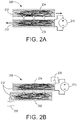
- FIGS. 1(a) - 1(c) a schematic illustrating a system 200 for electrocaloric cooling via active regeneration may be appreciated.
- the system 200 provides a first EC capacitor 202 and a second EC capacitor 204.
- the electric fields applied to this second EC capacitor 204 are complementary to the electric fields applied to the first EC capacitor 202 so that the temperature of the second EC capacitor 204 increases while the temperature of the first EC capacitor 202 decreases, and vice-versa.
- FIG. 1(c) provides a temperature scale to aid in interpreting the temperatures across each of the EC capacitors 202 and 204 during various system phases. It should be noted that while FIGS.
- the sections may indeed be of different EC materials tuned to work optimally at different temperatures or the sections may be of homogeneous EC material with the sections illustrating the temperature gradient across the homogeneous EC material.
- FIG. 1(a) illustrates the regeneration phase of the system 200.
- the first EC capacitor 202 is relatively hot (a high electric field is being applied) while the second EC capacitor 204 is relatively cold (a low electric field is being applied). Heat is transferred from the first EC capacitor 202 to the second EC capacitor 204.
- each of the first and second EC capacitors 202 and 204 comprises a plurality electrocaloric materials 212.
- the plurality of electrocaloric materials 212 are in a series, or side-by-side, orientation, however, the electrocaloric materials may also be layered or otherwise intermixed to produce a desired electrocaloric capacitor with desired electrocaloric function.
- FIG. 1(b) illustrates the heat transfer phase of the system 200.
- the second EC capacitor 204 has been shifted, or displaced, relative to the fixed position of the first EC capacitor 202; either or both of the EC capacitors 202 and 204 may be displaced as appropriate to a specific application.
- the second EC capacitor 204 is relatively hot (a high electric field is being applied) while the first EC capacitor 202 is relatively cold (a low electric field is being applied) so heat is transferred from the second EC capacitor 204 to the first EC capacitor 202.
- the hot side of the second EC capacitor 204 is in contact with a heat sink 206 at a hot temperature, T h
- the cold side of the first EC capacitor 202 is in contact with the object 208 to be cooled at a cold temperature, T c , wherein T c ⁇ T h .
- the vertically-oriented arrows in FIGS. 1(a) and 1(b) indicate the direction of heat flow. It should be noted that the temperatures of the two capacitors 202 and 204 are not constant; there is a temperature gradient across each of capacitors 202 and 204 at all times, i.e., hotter on the right and cooler on the left.
- FIGS. 2(a) and 2(b) similarly illustrate system 200 with first EC capacitor 202 and second EC capacitor 204.
- FIG. 2(a) illustrates the regeneration phase of the system 200 with a voltage source 210 applying a high electric field to the first EC capacitor 202 while the second EC capacitor 204 is submitted to a low electric field, indicated by the absence of a voltage source, keeping the second EC capacitor 204 relatively cool.
- Side arrows indicate displacement motion of the EC capacitor(s) 202 and 204; either or both may be displaced.
- Vertically-oriented arrows indicate the direction of heat transfer from the first EC capacitor 202 to the second EC capacitor 204.
- FIG. 2(b) illustrates the heat transfer phase of the system 200 wherein a high electric field, generated by voltage source 210, is applied to the second EC capacitor 204 and a low electric field, indicated by absence of a voltage source, is applied to the first capacitor 202.
- Heat sink 206 is again provided to the hot side of the second EC capacitor 204 and an object 208 to be cooled is again provided to the cold side of the first EC capacitor 202.
- the vertically-oriented arrows once again indicate the direction of heat transfer.
- FIGS. 2(a) and 2(b) further emphasize that each of the EC capacitors is fabricated from one or more EC materials 212 which may comprise an electrocaloric polymer, an electrocaloric co-polymer and/or an electrocaloric ceramic. Polymers generally have a low elastic modulus while ceramics can be brittle. As such, it may be necessary to reinforce the EC capacitors with metal foil or other supportive material.
- the electrocaloric cooling via active regeneration system 200 of FIGS. 1 and 2 is a four stage cycle: (1) move one direction, e.g., move the second EC capacitor 204 to the left relative to the first EC capacitor 202; (2) increase the first of the two electric fields while keeping the other low, e.g., increase the electric field on the first EC capacitor 202; (3) move the other direction, e.g., move the second EC capacitor 204 to the right relative to the first EC capacitor 202; and (4) increase the second of the two electric field while keeping the other low, e.g., increase the electric field on the second EC capacitor 204.
- Each of the steps provides discrete motion and field changes; however, the system 200 may also be continuous.
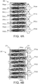
- FIG. 3(a) depicts the waveforms associated with discrete motion and field changes and specifically illustrates the position, the electric field on the first EC capacitor 202, and the electric field on the second EC capacitor 204 relative to time.
- FIG. 3(b) depicts the waveforms associated with continuous motion and field changes and specifically illustrates the position, the electric field on the first EC capacitor 202, and the electric field on the second EC capacitor 204 relative to time. While FIG. 3(b) depicts a ramp waveform, it should be noted that other types of continuous waveforms, e.g., sinusoidal, are also possible as long as the system 200 is properly synchronized.
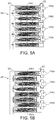
- FIGS. 1 and 2 have illustrated an example embodiment of the system 200 with only two EC capacitor layers (202 and 204), in practice, many layers of EC capacitors may be stacked.
- side arrows indicate the direction of motion and vertically-oriented arrows indicate the direction of heat transfer.
- the heat sink 206 and the object 208 to be cooled are also incorporated in the configuration of FIG. 4(b) . Any number of EC capacitor layers may be used as suitable to a specific application.
- the motion of one or both of the EC capacitors 202 and 204 may be achieved with a motor or other actuator.
- the alternate EC capacitor layers may be attached to one another to provide substantially uniform and simultaneous movement.
- a layer of lubrication may be provided intermediate each EC capacitor layer.
- the lubricant may comprise a thermally conductive oil or, alternatively, may comprise any other suitable oil or liquid lubricant and/or a solid lubricant such as graphite, or an oil containing particles of thermally-conductive or thermally-insulating materials.
- the length of motion (or displacement distance) for the EC capacitance layers, the EC capacitance layer thickness, the electric field generating voltage, etc. are dependent on material and system choices and can thus be selected appropriate to a specific application.
- the heat sink 206 and the object 208 to be cooled may be connected to the system 200 in any manner suitable to a specific application.
- the heat sink 206 and the object 208 may be connected to the system 200 through a liquid loop or other pumped liquid cooling.
- solid coupling such as in the form of metal blocks 222 may be used. See FIG. 5(a) where the EC capacitor layers 202 and 204 are positioned proximate metal blocks 222 and FIG. 5(b) where motion has caused EC capacitors to be in heat transfer contact with the metal blocks 222.
- the metal blocks 222 may, in turn, be coupled to the heat sink and the object to be cooled and/or an air heat exchanger or liquid loop, etc. While examples of system 200 connectors have been described herein, any other suitable heat exchange mechanism may be used to connect to the system 200.
- FIG. 6(a) which illustrates system 200 in a wedge configuration within a heat transfer material 224 where rotational motion is enabled.
- FIG. 6(b) is a sectional view of FIG. 6(a) illustrating the first EC capacitor 202 and the second EC capacitor 204, which is capable of rotational motion relative to the first EC capacitor 202.
- the various embodiments of the system 200 described herein may provide the advantage of higher power density and/or higher temperature lift through more active material volume as well as higher efficiency through more effective heat transfer.
- the core system described above may alternatively be configured as a pyroelectric heat engine.
- a pyroelectric material is substituted for the electrocaloric material.
- the pyroelectric material is selected to optimize heat energy harvesting.
- heat is absorbed by the device at the hot side and rejected at the cold side.
- the high voltage supplies of the cooling configuration are replaced by loads in the heat engine configuration.
- the loads may be passive or active with impedances or voltages synchronized with the motion of the capacitors.
- FIGS. 7(a) - 7(c) illustrate a system 700 for pyroelectric power generation with active regeneration.
- the system 700 provides a first pyroelectric (PE) capacitor 702 and a second PE capacitor 704.
- a heat source 706 and a heat sink 708 are also provided.
- FIG. 7(c) provides a temperature scale to aid in interpreting the temperatures across each of the PE capacitors 702 and 704 during various system phases.
- FIGS. 7(a) - 7(c) illustrate discrete sections within each of capacitors 702 and 704, the sections may indeed be of different PE materials tuned to work optimally at different temperatures or the sections may be of homogeneous PE material with the sections illustrating the temperature gradient across the homogeneous PE material.
- FIG. 7(a) illustrates one phase of a thermodynamic cycle within the pyroelectric heat engine.
- PE capacitor 702 is moved so that its hotter side is in communication with the heat source 706 while its voltage decreased such that it absorbs heat.
- PE capacitor 704, which is in communication with PE capacitor 702 has its voltage increased so that it rejects heat to the PE capacitor 702.
- PE capacitor 702 is moved so that its colder side is in communication with the heat sink 708. Its voltage is increased so that it rejects heat to the heat sink 708 as well as to PE capacitor 704, which has its voltage decreased. Because of the pyroelectric effect, the net electrical energy in terms of charge times voltage put into the system per cycle is less than the energy extracted. In this way, the device operates as a heat engine.
- Other configurations of pyroelectric capacitors, heat sources, and heat sinks are possible, and other pyroelectric energy harvesting cycles are also possible.
- Systems, devices or methods disclosed herein may include one or more of the features structures, methods, or combination thereof described herein.
- a device or method may be implemented to include one or more of the features and/or processes above. It is intended that such device or method need not include all of the features and/or processes described herein, but may be implemented to include selected features and/or processes that provide useful structures and/or functionality.
Landscapes
- Engineering & Computer Science (AREA)
- Physics & Mathematics (AREA)
- Mechanical Engineering (AREA)
- Thermal Sciences (AREA)
- General Engineering & Computer Science (AREA)
- Electric Double-Layer Capacitors Or The Like (AREA)
- Electric Propulsion And Braking For Vehicles (AREA)
Applications Claiming Priority (1)
| Application Number | Priority Date | Filing Date | Title |
|---|---|---|---|
| US14/306,871 US9429344B2 (en) | 2014-06-17 | 2014-06-17 | Electrocaloric system with active regeneration |
Publications (3)
| Publication Number | Publication Date |
|---|---|
| EP2957843A2 EP2957843A2 (en) | 2015-12-23 |
| EP2957843A3 EP2957843A3 (en) | 2016-05-25 |
| EP2957843B1 true EP2957843B1 (en) | 2017-12-27 |
Family
ID=53442479
Family Applications (1)
| Application Number | Title | Priority Date | Filing Date |
|---|---|---|---|
| EP15170173.7A Not-in-force EP2957843B1 (en) | 2014-06-17 | 2015-06-01 | Electrocaloric system with active regeneration |
Country Status (3)
| Country | Link |
|---|---|
| US (1) | US9429344B2 (enExample) |
| EP (1) | EP2957843B1 (enExample) |
| JP (1) | JP6937546B2 (enExample) |
Families Citing this family (52)
| Publication number | Priority date | Publication date | Assignee | Title |
|---|---|---|---|---|
| US10126025B2 (en) | 2013-08-02 | 2018-11-13 | Haier Us Appliance Solutions, Inc. | Magneto caloric assemblies |
| US9851128B2 (en) | 2014-04-22 | 2017-12-26 | Haier Us Appliance Solutions, Inc. | Magneto caloric heat pump |
| US10299655B2 (en) | 2016-05-16 | 2019-05-28 | General Electric Company | Caloric heat pump dishwasher appliance |
| US10281177B2 (en) | 2016-07-19 | 2019-05-07 | Haier Us Appliance Solutions, Inc. | Caloric heat pump system |
| US10274231B2 (en) | 2016-07-19 | 2019-04-30 | Haier Us Appliance Solutions, Inc. | Caloric heat pump system |
| US10006674B2 (en) | 2016-07-19 | 2018-06-26 | Haier Us Appliance Solutions, Inc. | Linearly-actuated magnetocaloric heat pump |
| US10295227B2 (en) | 2016-07-19 | 2019-05-21 | Haier Us Appliance Solutions, Inc. | Caloric heat pump system |
| US10047980B2 (en) | 2016-07-19 | 2018-08-14 | Haier Us Appliance Solutions, Inc. | Linearly-actuated magnetocaloric heat pump |
| US10006675B2 (en) | 2016-07-19 | 2018-06-26 | Haier Us Appliance Solutions, Inc. | Linearly-actuated magnetocaloric heat pump |
| US10047979B2 (en) | 2016-07-19 | 2018-08-14 | Haier Us Appliance Solutions, Inc. | Linearly-actuated magnetocaloric heat pump |
| US9915448B2 (en) | 2016-07-19 | 2018-03-13 | Haier Us Appliance Solutions, Inc. | Linearly-actuated magnetocaloric heat pump |
| US9869493B1 (en) | 2016-07-19 | 2018-01-16 | Haier Us Appliance Solutions, Inc. | Linearly-actuated magnetocaloric heat pump |
| US10006673B2 (en) | 2016-07-19 | 2018-06-26 | Haier Us Appliance Solutions, Inc. | Linearly-actuated magnetocaloric heat pump |
| US10006672B2 (en) | 2016-07-19 | 2018-06-26 | Haier Us Appliance Solutions, Inc. | Linearly-actuated magnetocaloric heat pump |
| US10222101B2 (en) | 2016-07-19 | 2019-03-05 | Haier Us Appliance Solutions, Inc. | Linearly-actuated magnetocaloric heat pump |
| WO2018017759A1 (en) * | 2016-07-21 | 2018-01-25 | Siemens Healthcare Diagnostics Inc. | Temperature controlled transport puck |
| US10443585B2 (en) | 2016-08-26 | 2019-10-15 | Haier Us Appliance Solutions, Inc. | Pump for a heat pump system |
| US9857106B1 (en) | 2016-10-10 | 2018-01-02 | Haier Us Appliance Solutions, Inc. | Heat pump valve assembly |
| US9857105B1 (en) | 2016-10-10 | 2018-01-02 | Haier Us Appliance Solutions, Inc. | Heat pump with a compliant seal |
| US10386096B2 (en) | 2016-12-06 | 2019-08-20 | Haier Us Appliance Solutions, Inc. | Magnet assembly for a magneto-caloric heat pump |
| US10288326B2 (en) | 2016-12-06 | 2019-05-14 | Haier Us Appliance Solutions, Inc. | Conduction heat pump |
| US20180164001A1 (en) * | 2016-12-12 | 2018-06-14 | Palo Alto Research Center Incorporated | Electrocaloric system |
| JP6772878B2 (ja) * | 2017-02-13 | 2020-10-21 | 株式会社村田製作所 | 熱マネジメント方法 |
| US11009282B2 (en) | 2017-03-28 | 2021-05-18 | Haier Us Appliance Solutions, Inc. | Refrigerator appliance with a caloric heat pump |
| US10527325B2 (en) | 2017-03-28 | 2020-01-07 | Haier Us Appliance Solutions, Inc. | Refrigerator appliance |
| US10451320B2 (en) | 2017-05-25 | 2019-10-22 | Haier Us Appliance Solutions, Inc. | Refrigerator appliance with water condensing features |
| US10422555B2 (en) | 2017-07-19 | 2019-09-24 | Haier Us Appliance Solutions, Inc. | Refrigerator appliance with a caloric heat pump |
| US10451322B2 (en) | 2017-07-19 | 2019-10-22 | Haier Us Appliance Solutions, Inc. | Refrigerator appliance with a caloric heat pump |
| US10520229B2 (en) | 2017-11-14 | 2019-12-31 | Haier Us Appliance Solutions, Inc. | Caloric heat pump for an appliance |
| US11022348B2 (en) | 2017-12-12 | 2021-06-01 | Haier Us Appliance Solutions, Inc. | Caloric heat pump for an appliance |
| US10876770B2 (en) | 2018-04-18 | 2020-12-29 | Haier Us Appliance Solutions, Inc. | Method for operating an elasto-caloric heat pump with variable pre-strain |
| US10830506B2 (en) | 2018-04-18 | 2020-11-10 | Haier Us Appliance Solutions, Inc. | Variable speed magneto-caloric thermal diode assembly |
| US10551095B2 (en) | 2018-04-18 | 2020-02-04 | Haier Us Appliance Solutions, Inc. | Magneto-caloric thermal diode assembly |
| US10648705B2 (en) | 2018-04-18 | 2020-05-12 | Haier Us Appliance Solutions, Inc. | Magneto-caloric thermal diode assembly |
| US10648704B2 (en) | 2018-04-18 | 2020-05-12 | Haier Us Appliance Solutions, Inc. | Magneto-caloric thermal diode assembly |
| US10648706B2 (en) | 2018-04-18 | 2020-05-12 | Haier Us Appliance Solutions, Inc. | Magneto-caloric thermal diode assembly with an axially pinned magneto-caloric cylinder |
| US10641539B2 (en) | 2018-04-18 | 2020-05-05 | Haier Us Appliance Solutions, Inc. | Magneto-caloric thermal diode assembly |
| US10557649B2 (en) | 2018-04-18 | 2020-02-11 | Haier Us Appliance Solutions, Inc. | Variable temperature magneto-caloric thermal diode assembly |
| US10782051B2 (en) | 2018-04-18 | 2020-09-22 | Haier Us Appliance Solutions, Inc. | Magneto-caloric thermal diode assembly |
| US11054176B2 (en) | 2018-05-10 | 2021-07-06 | Haier Us Appliance Solutions, Inc. | Magneto-caloric thermal diode assembly with a modular magnet system |
| US11015842B2 (en) | 2018-05-10 | 2021-05-25 | Haier Us Appliance Solutions, Inc. | Magneto-caloric thermal diode assembly with radial polarity alignment |
| US10989449B2 (en) | 2018-05-10 | 2021-04-27 | Haier Us Appliance Solutions, Inc. | Magneto-caloric thermal diode assembly with radial supports |
| US10684044B2 (en) | 2018-07-17 | 2020-06-16 | Haier Us Appliance Solutions, Inc. | Magneto-caloric thermal diode assembly with a rotating heat exchanger |
| US11092364B2 (en) | 2018-07-17 | 2021-08-17 | Haier Us Appliance Solutions, Inc. | Magneto-caloric thermal diode assembly with a heat transfer fluid circuit |
| WO2020106718A1 (en) | 2018-11-19 | 2020-05-28 | Carrier Corporation | Electrocaloric heat transfer system and a method of operating the same |
| US11193697B2 (en) | 2019-01-08 | 2021-12-07 | Haier Us Appliance Solutions, Inc. | Fan speed control method for caloric heat pump systems |
| US11168926B2 (en) | 2019-01-08 | 2021-11-09 | Haier Us Appliance Solutions, Inc. | Leveraged mechano-caloric heat pump |
| US11149994B2 (en) | 2019-01-08 | 2021-10-19 | Haier Us Appliance Solutions, Inc. | Uneven flow valve for a caloric regenerator |
| US11274860B2 (en) | 2019-01-08 | 2022-03-15 | Haier Us Appliance Solutions, Inc. | Mechano-caloric stage with inner and outer sleeves |
| US11112146B2 (en) | 2019-02-12 | 2021-09-07 | Haier Us Appliance Solutions, Inc. | Heat pump and cascaded caloric regenerator assembly |
| US11015843B2 (en) | 2019-05-29 | 2021-05-25 | Haier Us Appliance Solutions, Inc. | Caloric heat pump hydraulic system |
| US11187441B2 (en) * | 2019-10-10 | 2021-11-30 | Palo Alto Research Center Incorporated | Control system for an electrocaloric device |
Family Cites Families (18)
| Publication number | Priority date | Publication date | Assignee | Title |
|---|---|---|---|---|
| DE4242642C2 (de) * | 1992-12-17 | 1996-10-17 | Deutsche Forsch Luft Raumfahrt | Wärmepumpverfahren sowie Wärmepumpe, insbesondere zur Erzeugung kryogener Temperaturen |
| DE4329898A1 (de) * | 1993-09-04 | 1995-04-06 | Marcus Dr Besson | Kabelloses medizinisches Diagnose- und Überwachungsgerät |
| US5644184A (en) * | 1996-02-15 | 1997-07-01 | Thermodyne, Inc. | Piezo-pyroelectric energy converter and method |
| US6856037B2 (en) * | 2001-11-26 | 2005-02-15 | Sony Corporation | Method and apparatus for converting dissipated heat to work energy |
| US6588215B1 (en) * | 2002-04-19 | 2003-07-08 | International Business Machines Corporation | Apparatus and methods for performing switching in magnetic refrigeration systems using inductively coupled thermoelectric switches |
| US6877325B1 (en) * | 2002-06-27 | 2005-04-12 | Ceramphysics, Inc. | Electrocaloric device and thermal transfer systems employing the same |
| WO2008007834A1 (en) * | 2006-07-10 | 2008-01-17 | Daewoo Electronics Corporation | Shuttle type magnetic refrigerator |
| EP2165074B1 (en) * | 2007-06-08 | 2017-03-15 | Carver Scientific, Inc. | Device and method for converting thermal energy into electrical energy |
| GB0720939D0 (en) * | 2007-10-24 | 2007-12-05 | Powell Jude A | Coolign device |
| US20100175392A1 (en) * | 2009-01-15 | 2010-07-15 | Malloy Kevin J | Electrocaloric refrigerator and multilayer pyroelectric energy generator |
| US8344585B2 (en) * | 2009-05-14 | 2013-01-01 | The Neothermal Energy Company | Method and apparatus for conversion of heat to electrical energy using a new thermodynamic cycle |
| US8695353B2 (en) | 2009-12-17 | 2014-04-15 | Empire Technology Development Llc | Electrocaloric cooling |
| US9508913B2 (en) * | 2010-06-18 | 2016-11-29 | Empire Technology Development Llc | Electrocaloric effect materials and thermal diodes |
| GB201111235D0 (en) * | 2011-06-30 | 2011-08-17 | Camfridge Ltd | Multi-Material-Blade for active regenerative magneto-caloric or electro-caloricheat engines |
| WO2013043169A1 (en) | 2011-09-21 | 2013-03-28 | Empire Technology Development Llc | Heterogeneous electrocaloric effect heat transfer |
| KR101887917B1 (ko) * | 2012-01-16 | 2018-09-20 | 삼성전자주식회사 | 자기 냉각 장치 및 그 제어 방법 |
| WO2014014448A1 (en) * | 2012-07-17 | 2014-01-23 | Empire Technology Development Llc | Multistage thermal flow device and thermal energy transfer |
| US9109818B2 (en) * | 2013-09-20 | 2015-08-18 | Palo Alto Research Center Incorporated | Electrocaloric cooler and heat pump |
-
2014
- 2014-06-17 US US14/306,871 patent/US9429344B2/en active Active
-
2015
- 2015-05-27 JP JP2015107143A patent/JP6937546B2/ja active Active
- 2015-06-01 EP EP15170173.7A patent/EP2957843B1/en not_active Not-in-force
Non-Patent Citations (1)
| Title |
|---|
| None * |
Also Published As
| Publication number | Publication date |
|---|---|
| JP2016005429A (ja) | 2016-01-12 |
| US9429344B2 (en) | 2016-08-30 |
| EP2957843A3 (en) | 2016-05-25 |
| JP6937546B2 (ja) | 2021-09-22 |
| EP2957843A2 (en) | 2015-12-23 |
| US20150362225A1 (en) | 2015-12-17 |
Similar Documents
| Publication | Publication Date | Title |
|---|---|---|
| EP2957843B1 (en) | Electrocaloric system with active regeneration | |
| US20230280073A1 (en) | Electrocaloric system | |
| Meng et al. | Electrocaloric cooling over high device temperature span | |
| Zhang et al. | An electrocaloric refrigerator with direct solid to solid regeneration | |
| EP3027980B1 (en) | Method for electrocaloric energy conversion | |
| US10107527B2 (en) | Field-active direct contact regenerator | |
| Ma et al. | Highly efficient electrocaloric cooling with electrostatic actuation | |
| Guo et al. | Design and modeling of a fluid-based micro-scale electrocaloric refrigeration system | |
| Ossmer et al. | Energy-efficient miniature-scale heat pumping based on shape memory alloys | |
| KR102126170B1 (ko) | 전기열량 냉각기 및 히트펌프 | |
| Zabek et al. | A novel pyroelectric generator utilising naturally driven temperature fluctuations from oscillating heat pipes for waste heat recovery and thermal energy harvesting | |
| JP5464614B2 (ja) | 磁気熱量による熱発生器 | |
| Navid et al. | Towards optimization of a pyroelectric energy converter for harvesting waste heat | |
| US20150033762A1 (en) | Regenerative electrocaloric cooling device | |
| JP2016005429A5 (enExample) | ||
| Vanderpool et al. | Simulations of a prototypical device using pyroelectric materials for harvesting waste heat | |
| CN102403925B (zh) | 一种往复式运动活塞泵驱动的热磁发电系统 | |
| Xavier et al. | It’s not about the mass | |
| WO2016089401A1 (en) | Field-active heat pumping using liquid materials | |
| Kholkin et al. | Electrocaloric-based applications: Challenges and perspectives | |
| Novak et al. | Electrocaloric devices using cantilever structures | |
| KR101454107B1 (ko) | 고효율 열전 발전부품 및 그 제조방법 | |
| Vanderpool et al. | Optimum operation of a prototypical pyroelectric energy converter for harvesting waste heat | |
| HK1125164A (en) | Heat exchanger for thermoelectric applications |
Legal Events
| Date | Code | Title | Description |
|---|---|---|---|
| PUAI | Public reference made under article 153(3) epc to a published international application that has entered the european phase |
Free format text: ORIGINAL CODE: 0009012 |
|
| AK | Designated contracting states |
Kind code of ref document: A2 Designated state(s): AL AT BE BG CH CY CZ DE DK EE ES FI FR GB GR HR HU IE IS IT LI LT LU LV MC MK MT NL NO PL PT RO RS SE SI SK SM TR |
|
| AX | Request for extension of the european patent |
Extension state: BA ME |
|
| PUAL | Search report despatched |
Free format text: ORIGINAL CODE: 0009013 |
|
| AK | Designated contracting states |
Kind code of ref document: A3 Designated state(s): AL AT BE BG CH CY CZ DE DK EE ES FI FR GB GR HR HU IE IS IT LI LT LU LV MC MK MT NL NO PL PT RO RS SE SI SK SM TR |
|
| AX | Request for extension of the european patent |
Extension state: BA ME |
|
| RIC1 | Information provided on ipc code assigned before grant |
Ipc: F25B 21/00 20060101AFI20160418BHEP |
|
| 17P | Request for examination filed |
Effective date: 20161125 |
|
| RBV | Designated contracting states (corrected) |
Designated state(s): AL AT BE BG CH CY CZ DE DK EE ES FI FR GB GR HR HU IE IS IT LI LT LU LV MC MK MT NL NO PL PT RO RS SE SI SK SM TR |
|
| 17Q | First examination report despatched |
Effective date: 20170222 |
|
| GRAP | Despatch of communication of intention to grant a patent |
Free format text: ORIGINAL CODE: EPIDOSNIGR1 |
|
| INTG | Intention to grant announced |
Effective date: 20170721 |
|
| GRAS | Grant fee paid |
Free format text: ORIGINAL CODE: EPIDOSNIGR3 |
|
| GRAA | (expected) grant |
Free format text: ORIGINAL CODE: 0009210 |
|
| AK | Designated contracting states |
Kind code of ref document: B1 Designated state(s): AL AT BE BG CH CY CZ DE DK EE ES FI FR GB GR HR HU IE IS IT LI LT LU LV MC MK MT NL NO PL PT RO RS SE SI SK SM TR |
|
| REG | Reference to a national code |
Ref country code: GB Ref legal event code: FG4D |
|
| REG | Reference to a national code |
Ref country code: CH Ref legal event code: EP |
|
| REG | Reference to a national code |
Ref country code: AT Ref legal event code: REF Ref document number: 958639 Country of ref document: AT Kind code of ref document: T Effective date: 20180115 |
|
| REG | Reference to a national code |
Ref country code: IE Ref legal event code: FG4D |
|
| REG | Reference to a national code |
Ref country code: DE Ref legal event code: R096 Ref document number: 602015006952 Country of ref document: DE |
|
| PG25 | Lapsed in a contracting state [announced via postgrant information from national office to epo] |
Ref country code: NO Free format text: LAPSE BECAUSE OF FAILURE TO SUBMIT A TRANSLATION OF THE DESCRIPTION OR TO PAY THE FEE WITHIN THE PRESCRIBED TIME-LIMIT Effective date: 20180327 Ref country code: FI Free format text: LAPSE BECAUSE OF FAILURE TO SUBMIT A TRANSLATION OF THE DESCRIPTION OR TO PAY THE FEE WITHIN THE PRESCRIBED TIME-LIMIT Effective date: 20171227 Ref country code: LT Free format text: LAPSE BECAUSE OF FAILURE TO SUBMIT A TRANSLATION OF THE DESCRIPTION OR TO PAY THE FEE WITHIN THE PRESCRIBED TIME-LIMIT Effective date: 20171227 |
|
| REG | Reference to a national code |
Ref country code: NL Ref legal event code: MP Effective date: 20171227 |
|
| REG | Reference to a national code |
Ref country code: LT Ref legal event code: MG4D |
|
| REG | Reference to a national code |
Ref country code: AT Ref legal event code: MK05 Ref document number: 958639 Country of ref document: AT Kind code of ref document: T Effective date: 20171227 |
|
| PG25 | Lapsed in a contracting state [announced via postgrant information from national office to epo] |
Ref country code: RS Free format text: LAPSE BECAUSE OF FAILURE TO SUBMIT A TRANSLATION OF THE DESCRIPTION OR TO PAY THE FEE WITHIN THE PRESCRIBED TIME-LIMIT Effective date: 20171227 Ref country code: GR Free format text: LAPSE BECAUSE OF FAILURE TO SUBMIT A TRANSLATION OF THE DESCRIPTION OR TO PAY THE FEE WITHIN THE PRESCRIBED TIME-LIMIT Effective date: 20180328 Ref country code: BG Free format text: LAPSE BECAUSE OF FAILURE TO SUBMIT A TRANSLATION OF THE DESCRIPTION OR TO PAY THE FEE WITHIN THE PRESCRIBED TIME-LIMIT Effective date: 20180327 Ref country code: HR Free format text: LAPSE BECAUSE OF FAILURE TO SUBMIT A TRANSLATION OF THE DESCRIPTION OR TO PAY THE FEE WITHIN THE PRESCRIBED TIME-LIMIT Effective date: 20171227 Ref country code: LV Free format text: LAPSE BECAUSE OF FAILURE TO SUBMIT A TRANSLATION OF THE DESCRIPTION OR TO PAY THE FEE WITHIN THE PRESCRIBED TIME-LIMIT Effective date: 20171227 |
|
| REG | Reference to a national code |
Ref country code: FR Ref legal event code: PLFP Year of fee payment: 4 |
|
| PG25 | Lapsed in a contracting state [announced via postgrant information from national office to epo] |
Ref country code: NL Free format text: LAPSE BECAUSE OF FAILURE TO SUBMIT A TRANSLATION OF THE DESCRIPTION OR TO PAY THE FEE WITHIN THE PRESCRIBED TIME-LIMIT Effective date: 20171227 |
|
| PG25 | Lapsed in a contracting state [announced via postgrant information from national office to epo] |
Ref country code: ES Free format text: LAPSE BECAUSE OF FAILURE TO SUBMIT A TRANSLATION OF THE DESCRIPTION OR TO PAY THE FEE WITHIN THE PRESCRIBED TIME-LIMIT Effective date: 20171227 Ref country code: EE Free format text: LAPSE BECAUSE OF FAILURE TO SUBMIT A TRANSLATION OF THE DESCRIPTION OR TO PAY THE FEE WITHIN THE PRESCRIBED TIME-LIMIT Effective date: 20171227 Ref country code: CY Free format text: LAPSE BECAUSE OF FAILURE TO SUBMIT A TRANSLATION OF THE DESCRIPTION OR TO PAY THE FEE WITHIN THE PRESCRIBED TIME-LIMIT Effective date: 20171227 Ref country code: SK Free format text: LAPSE BECAUSE OF FAILURE TO SUBMIT A TRANSLATION OF THE DESCRIPTION OR TO PAY THE FEE WITHIN THE PRESCRIBED TIME-LIMIT Effective date: 20171227 Ref country code: CZ Free format text: LAPSE BECAUSE OF FAILURE TO SUBMIT A TRANSLATION OF THE DESCRIPTION OR TO PAY THE FEE WITHIN THE PRESCRIBED TIME-LIMIT Effective date: 20171227 |
|
| PG25 | Lapsed in a contracting state [announced via postgrant information from national office to epo] |
Ref country code: AT Free format text: LAPSE BECAUSE OF FAILURE TO SUBMIT A TRANSLATION OF THE DESCRIPTION OR TO PAY THE FEE WITHIN THE PRESCRIBED TIME-LIMIT Effective date: 20171227 Ref country code: IT Free format text: LAPSE BECAUSE OF FAILURE TO SUBMIT A TRANSLATION OF THE DESCRIPTION OR TO PAY THE FEE WITHIN THE PRESCRIBED TIME-LIMIT Effective date: 20171227 Ref country code: RO Free format text: LAPSE BECAUSE OF FAILURE TO SUBMIT A TRANSLATION OF THE DESCRIPTION OR TO PAY THE FEE WITHIN THE PRESCRIBED TIME-LIMIT Effective date: 20171227 Ref country code: SM Free format text: LAPSE BECAUSE OF FAILURE TO SUBMIT A TRANSLATION OF THE DESCRIPTION OR TO PAY THE FEE WITHIN THE PRESCRIBED TIME-LIMIT Effective date: 20171227 Ref country code: IS Free format text: LAPSE BECAUSE OF FAILURE TO SUBMIT A TRANSLATION OF THE DESCRIPTION OR TO PAY THE FEE WITHIN THE PRESCRIBED TIME-LIMIT Effective date: 20180427 Ref country code: PL Free format text: LAPSE BECAUSE OF FAILURE TO SUBMIT A TRANSLATION OF THE DESCRIPTION OR TO PAY THE FEE WITHIN THE PRESCRIBED TIME-LIMIT Effective date: 20171227 |
|
| REG | Reference to a national code |
Ref country code: DE Ref legal event code: R097 Ref document number: 602015006952 Country of ref document: DE |
|
| PLBE | No opposition filed within time limit |
Free format text: ORIGINAL CODE: 0009261 |
|
| STAA | Information on the status of an ep patent application or granted ep patent |
Free format text: STATUS: NO OPPOSITION FILED WITHIN TIME LIMIT |
|
| PG25 | Lapsed in a contracting state [announced via postgrant information from national office to epo] |
Ref country code: DK Free format text: LAPSE BECAUSE OF FAILURE TO SUBMIT A TRANSLATION OF THE DESCRIPTION OR TO PAY THE FEE WITHIN THE PRESCRIBED TIME-LIMIT Effective date: 20171227 |
|
| 26N | No opposition filed |
Effective date: 20180928 |
|
| REG | Reference to a national code |
Ref country code: CH Ref legal event code: PL |
|
| PG25 | Lapsed in a contracting state [announced via postgrant information from national office to epo] |
Ref country code: SI Free format text: LAPSE BECAUSE OF FAILURE TO SUBMIT A TRANSLATION OF THE DESCRIPTION OR TO PAY THE FEE WITHIN THE PRESCRIBED TIME-LIMIT Effective date: 20171227 |
|
| REG | Reference to a national code |
Ref country code: BE Ref legal event code: MM Effective date: 20180630 |
|
| REG | Reference to a national code |
Ref country code: IE Ref legal event code: MM4A |
|
| PG25 | Lapsed in a contracting state [announced via postgrant information from national office to epo] |
Ref country code: LU Free format text: LAPSE BECAUSE OF NON-PAYMENT OF DUE FEES Effective date: 20180601 Ref country code: MC Free format text: LAPSE BECAUSE OF FAILURE TO SUBMIT A TRANSLATION OF THE DESCRIPTION OR TO PAY THE FEE WITHIN THE PRESCRIBED TIME-LIMIT Effective date: 20171227 |
|
| PG25 | Lapsed in a contracting state [announced via postgrant information from national office to epo] |
Ref country code: CH Free format text: LAPSE BECAUSE OF NON-PAYMENT OF DUE FEES Effective date: 20180630 Ref country code: LI Free format text: LAPSE BECAUSE OF NON-PAYMENT OF DUE FEES Effective date: 20180630 Ref country code: IE Free format text: LAPSE BECAUSE OF NON-PAYMENT OF DUE FEES Effective date: 20180601 |
|
| PG25 | Lapsed in a contracting state [announced via postgrant information from national office to epo] |
Ref country code: BE Free format text: LAPSE BECAUSE OF NON-PAYMENT OF DUE FEES Effective date: 20180630 |
|
| PG25 | Lapsed in a contracting state [announced via postgrant information from national office to epo] |
Ref country code: MT Free format text: LAPSE BECAUSE OF NON-PAYMENT OF DUE FEES Effective date: 20180601 |
|
| PG25 | Lapsed in a contracting state [announced via postgrant information from national office to epo] |
Ref country code: TR Free format text: LAPSE BECAUSE OF FAILURE TO SUBMIT A TRANSLATION OF THE DESCRIPTION OR TO PAY THE FEE WITHIN THE PRESCRIBED TIME-LIMIT Effective date: 20171227 |
|
| PG25 | Lapsed in a contracting state [announced via postgrant information from national office to epo] |
Ref country code: PT Free format text: LAPSE BECAUSE OF FAILURE TO SUBMIT A TRANSLATION OF THE DESCRIPTION OR TO PAY THE FEE WITHIN THE PRESCRIBED TIME-LIMIT Effective date: 20171227 |
|
| PG25 | Lapsed in a contracting state [announced via postgrant information from national office to epo] |
Ref country code: MK Free format text: LAPSE BECAUSE OF NON-PAYMENT OF DUE FEES Effective date: 20171227 Ref country code: SE Free format text: LAPSE BECAUSE OF FAILURE TO SUBMIT A TRANSLATION OF THE DESCRIPTION OR TO PAY THE FEE WITHIN THE PRESCRIBED TIME-LIMIT Effective date: 20171227 Ref country code: HU Free format text: LAPSE BECAUSE OF FAILURE TO SUBMIT A TRANSLATION OF THE DESCRIPTION OR TO PAY THE FEE WITHIN THE PRESCRIBED TIME-LIMIT; INVALID AB INITIO Effective date: 20150601 |
|
| PG25 | Lapsed in a contracting state [announced via postgrant information from national office to epo] |
Ref country code: AL Free format text: LAPSE BECAUSE OF FAILURE TO SUBMIT A TRANSLATION OF THE DESCRIPTION OR TO PAY THE FEE WITHIN THE PRESCRIBED TIME-LIMIT Effective date: 20171227 |
|
| PGFP | Annual fee paid to national office [announced via postgrant information from national office to epo] |
Ref country code: GB Payment date: 20200525 Year of fee payment: 6 |
|
| GBPC | Gb: european patent ceased through non-payment of renewal fee |
Effective date: 20210601 |
|
| PG25 | Lapsed in a contracting state [announced via postgrant information from national office to epo] |
Ref country code: GB Free format text: LAPSE BECAUSE OF NON-PAYMENT OF DUE FEES Effective date: 20210601 |
|
| PGFP | Annual fee paid to national office [announced via postgrant information from national office to epo] |
Ref country code: FR Payment date: 20220519 Year of fee payment: 8 Ref country code: DE Payment date: 20220518 Year of fee payment: 8 |
|
| REG | Reference to a national code |
Ref country code: DE Ref legal event code: R119 Ref document number: 602015006952 Country of ref document: DE |
|
| PG25 | Lapsed in a contracting state [announced via postgrant information from national office to epo] |
Ref country code: DE Free format text: LAPSE BECAUSE OF NON-PAYMENT OF DUE FEES Effective date: 20240103 |
|
| PG25 | Lapsed in a contracting state [announced via postgrant information from national office to epo] |
Ref country code: FR Free format text: LAPSE BECAUSE OF NON-PAYMENT OF DUE FEES Effective date: 20230630 |