EP2957836B1 - Fixing member, cooktop and cooking range with the same - Google Patents
Fixing member, cooktop and cooking range with the same Download PDFInfo
- Publication number
- EP2957836B1 EP2957836B1 EP15171303.9A EP15171303A EP2957836B1 EP 2957836 B1 EP2957836 B1 EP 2957836B1 EP 15171303 A EP15171303 A EP 15171303A EP 2957836 B1 EP2957836 B1 EP 2957836B1
- Authority
- EP
- European Patent Office
- Prior art keywords
- plate
- bracket
- mounting portion
- segment
- fixing member
- Prior art date
- Legal status (The legal status is an assumption and is not a legal conclusion. Google has not performed a legal analysis and makes no representation as to the accuracy of the status listed.)
- Active
Links
- 238000010411 cooking Methods 0.000 title claims description 12
- 238000010438 heat treatment Methods 0.000 claims description 18
- 238000000034 method Methods 0.000 claims description 12
- 239000012790 adhesive layer Substances 0.000 claims description 3
- 238000009434 installation Methods 0.000 description 4
- 239000000463 material Substances 0.000 description 4
- 238000004519 manufacturing process Methods 0.000 description 3
- 239000011521 glass Substances 0.000 description 2
- 230000003247 decreasing effect Effects 0.000 description 1
- 230000007547 defect Effects 0.000 description 1
- 239000003292 glue Substances 0.000 description 1
- 238000012423 maintenance Methods 0.000 description 1
- 238000003466 welding Methods 0.000 description 1
Images


Classifications
-
- H—ELECTRICITY
- H05—ELECTRIC TECHNIQUES NOT OTHERWISE PROVIDED FOR
- H05B—ELECTRIC HEATING; ELECTRIC LIGHT SOURCES NOT OTHERWISE PROVIDED FOR; CIRCUIT ARRANGEMENTS FOR ELECTRIC LIGHT SOURCES, IN GENERAL
- H05B3/00—Ohmic-resistance heating
- H05B3/68—Heating arrangements specially adapted for cooking plates or analogous hot-plates
- H05B3/74—Non-metallic plates, e.g. vitroceramic, ceramic or glassceramic hobs, also including power or control circuits
-
- F—MECHANICAL ENGINEERING; LIGHTING; HEATING; WEAPONS; BLASTING
- F24—HEATING; RANGES; VENTILATING
- F24C—DOMESTIC STOVES OR RANGES ; DETAILS OF DOMESTIC STOVES OR RANGES, OF GENERAL APPLICATION
- F24C7/00—Stoves or ranges heated by electric energy
- F24C7/06—Arrangement or mounting of electric heating elements
- F24C7/067—Arrangement or mounting of electric heating elements on ranges
-
- F—MECHANICAL ENGINEERING; LIGHTING; HEATING; WEAPONS; BLASTING
- F24—HEATING; RANGES; VENTILATING
- F24C—DOMESTIC STOVES OR RANGES ; DETAILS OF DOMESTIC STOVES OR RANGES, OF GENERAL APPLICATION
- F24C15/00—Details
- F24C15/30—Arrangements for mounting stoves or ranges in particular locations
Definitions
- the present invention relates to a technical field of kitchenware, and more particularly to a fixing member, a cooktop with the fixing member, and a cooking range with the cooktop.
- a fixing member for a heating unit has the following defects: large volume, complicated assembling and in a great quantity (three or more).
- Another objective of the present invention is to provide a cooktop with the above fixing member.
- Another objective of the present invention is to provide a cooking range with the above cooktop.
- the fixing member includes: a base plate defining a mounting hole; a connecting plate comprising a first plate segment connected at a first side of the base plate, a second plate segment, and a third plate segment substantially parallel to the base plate, the second plate segment being connected between the first and third plate segments; and a fixing plate defining a first end connected at a second side of the base plate and perpendicular to the base plate, and a second end having a snapping tongue bent and extended in a direction away from the connecting plate.
- a vertical distance between a free end of the snapping tongue and the base plate is equal to or smaller than that between the third plate segment and the base plate.
- the fixing member according to the embodiments of the present invention is convenient for assembling with a simple structure, and can fix the brackets in the cooktop of the cooking range stably.
- the second plate segment is configured as a sloping plate slantwise extended from the base plate to the third plate segment upwardly.
- the first plate segment is configured as a flat plate perpendicular to the base plate.
- the first plate segment is configured as an arc plate protruded in a direction away from the fixing plate.
- At least one of the first plate segment and the second plate segment is formed with a through-hole.
- a notch is formed at a free end of the third plate segment at a position corresponding to the snapping tongue.
- the fixing plate has a recess extended from an upper end of the fixing plate towards a lower end of the fixing plate, and an extension plate extended in a direction away from the base plate, in which the snapping tongue is disposed at a free end portion of the extension plate.
- the base plate, the connecting plate and the fixing plate are integrally formed via a stamping process.
- a cooktop includes: an annular plate defining an aperture therein and having an annular platform formed at an inner wall of the aperture; a panel fitted within the aperture and supported by the annular platform; a bracket detachably connected with the annular plate and located above the panel; a heating unit disposed between the panel and the bracket, and detachably mounted on the bracket via a fixing member according to the above embodiments; and an indicating lamp holder detachably mounted on the annular plate.
- the cooktop according to the embodiments of the present invention is convenient for assembling and disassembling with a simple structure, and has high efficiency and low cost.
- the fixing member is mounted on the heating unit by a bolt; the bracket has a snapping groove adapted to the snapping tongue.
- An upper surface of the third plate segment abuts against a lower surface of the bracket, and the snapping tongue passes through the snapping groove so as to abut against an upper surface of the bracket, such that the fixing member clamps the bracket.
- the bracket includes a first bracket and a second bracket parallel to each other and extended in a front-and-rear direction.
- a front mounting plate is connected with a front side wall of the aperture, is located below the annular platform, and has a first mounting portion, a second mounting portion and an inserting part between the first mounting portion and the second mounting portion, in which the indicating lamp holder is disposed in the inserting part.
- a rear mounting plate is connected with a rear side wall of the aperture, is located below the annular bearing platform, and has a third mounting portion corresponding to the first mounting portion and a fourth mounting portion corresponding to the second mounting portion.
- First and second ends of the first bracket are detachably connected to the first mounting portion and the third mounting portion respectively; first and second ends of the second bracket are detachably connected to the second mounting portion and the fourth mounting portion respectively.
- the annular plate is integrally formed by a stamping process.
- an adhesive layer is disposed between the panel and the annular platform.
- cooking range range includes the cooktop according to the above embodiments.
- first and second are used herein for purposes of description and are not intended to indicate or imply relative importance or significance or to imply the number of indicated technical features.
- the feature defined with “first” and “second” may explicitly or implicitly includes one or more of this feature.
- the term “a plurality of' means two or more than two, unless specified otherwise.
- the terms “mounted,” “connected,” “coupled” and the like are used broadly, and may be, for example, fixed connections, detachable connections, or integral connections; may also be direct connections or indirect connections via intervening structures, which can be understood by those skilled in the art according to specific situations.
- the fixing member 100 includes a base plate 10, a connecting plate 20 and a fixing plate 30.
- the base plate 10 defines a mounting hole 101.
- the mounting hole 101 may be an oblong hole, which can eliminate assembling errors.
- the connecting plate includes a first plate segment 201 connected at a first side of the base plate 10, a second plate segment 202, and a third plate segment 203 substantially parallel to the base plate 10, the second plate segment 202 being connected between the first and third plate segments.
- the fixing plate 30 defines a first end connected at a second side of the base plate 10 and perpendicular to the base plate 10, and a second end having a snapping tongue 301 bent and extended in a direction away from the connecting plate 20.
- a vertical distance between a free end of the snapping tongue 301 and the base plate 10 is equal to or smaller than that between the third plate segment 203 and the base plate 10.
- the base plate 10 is supposed at a horizontal plane, and the third plate segment 203 extends in a horizontal direction, such that the extension direction of each component is presented in Fig. 1 and Fig. 2 .
- a lower edge of the connecting plate is connected with a right edge of the base plate 10. More specifically, a lower edge of the first plate segment 201 is connected with the right edge of the base plate 10. A lower edge of the second plate segment 202 is connected with an upper edge of the first plate segment 201. A right edge of the third plate segment 203 is connected with an upper edge of the second plate segment 202.
- the first plate segment 201 and the second plate segment 202 both provide an upward elastic force for the third plate segment 203.
- a lower edge of the fixing plate 30 is connected with a left edge of the base plate 10, and an upper edge of the fixing plate 30 defines a snapping tongue 301.
- a horizontal position of a lower edge of the snapping tongue 301 is equal to or lower than an upper surface of the third plate segment 203.
- the bracket 400 has a snapping groove 410 adapted to the snapping tongue 301.
- the upper surface of the third plate segment 203 abuts against a lower surface of the bracket 400, and the snapping tongue 301 passes through the snapping groove 410, such that the lower edge of the snapping tongue 301 abuts against an upper surface of the bracket 400.
- the third plate segment 203 Since the horizontal position of the lower edge of the snapping tongue 301 is equal to or lower than the upper surface of the third plate segment 203, the third plate segment 203 is pressed downwards by the bracket 400, and hence bounces the bracket 400 upwards, but the lower edge of the snapping tongue 301 abuts against the upper surface of the bracket 400, such that the fixing member 100 clamps the bracket 400 elastically.
- the fixing member according to the embodiments of the present invention is convenient for assembling with a simple structure, and can fix the brackets in the cooktop of the cooking range stably.
- the second plate segment 202 is configured as a sloping plate slantwise extended from the base plate 10 to the third plate segment 203 upwardly, as shown in Fig. 1 and Fig. 2 .
- the first plate segment 201 is configured as a flat plate perpendicular to the base plate 10. In an example shown in Fig. 1 , the first plate segment 201 is configured as a flat plate vertically extends upwards. In some other alternative embodiments, as shown in Fig. 2 , the first plate segment 201 is configured as an arc plate protruded in a direction away from the fixing plate 30, such that the fixing member 100 is in a good elasticity.
- the through-hole 2012 can be formed in the first plate segment 201 alone, or in the second plate segment 202 alone, or in both the first plate segment 201 and the second plate segment 202, as shown in Fig. 1 and Fig. 2 .
- a notch 2031 is formed at a free end of the third plate segment 203 at a position corresponding to the snapping tongue 301.
- the fixing plate 30 has a recess 302 extended from an upper end of the fixing plate 30 towards a lower end of the fixing plate 30, and an extension plate 303 extended in a direction away from the base plate 10, in which the snapping tongue 301 is disposed at a free end portion of the extension plate 303, i.e. an upper end portion in Fig. 1 and Fig. 2 .
- the fixing plate 30 cannot only clamp the bracket 400, but also support the bracket 400.
- the base plate10, the connecting plate 20 and the fixing plate 30 are integrally formed.
- the base plate 10, the connecting plate 20 and the fixing plate 30 are integrally formed via a stamping process.
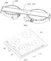
- the cooktop includes an annular plate 200, a panel 300, a bracket 400, a heating unit 500 and an indicating lamp holder 600.
- the annular plate 200 defines an aperture 210 therein and has an annular platform 211 formed at an inner wall of the aperture 210, as shown in Fig. 5 .
- the annular plate 200 is integrally formed by a stamping process.
- the indicating lamp holder 600 is detachably mounted on the annular plate 200.
- the panel 300 is fitted within the aperture 210 and supported by the annular platform 211.
- the panel 300 can be imbedded in the aperture 210 and supported by the annular platform 211, as shown in Fig. 3 and Fig. 8 .
- an adhesive layer is disposed between the panel 300 and the annular platform 211, to connect the panel 300 with the annular plate 200 firmly.
- the bracket 400 is detachably connected with the annular plate 200 and located below the panel 300.
- the bracket 400 may be snap-fitted or screw-connected with the annular plate.
- the heating unit 500 is disposed between the panel 300 and the bracket 400, and is detachably mounted on the bracket 400 via the fixing member according to the above embodiments.
- the cooktop according to the embodiments of the present invention is convenient for assembling and disassembling with a simple structure, and has high efficiency and low cost.
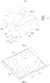
- the fixing member 100 is mounted on the heating unit 500 via a bolt 700, as shown in Fig. 6 .
- the bracket 400 has the snapping groove 410 adapted to the snapping tongue 301.
- the upper surface of the third plate segment 203 abuts against the lower surface of the bracket 400, and the snapping tongue 301 passes through the snapping groove 410, such that the lower edge of the snapping tongue 301 abuts against the upper surface of the bracket 400.
- the bolt 700 passes through the mounting hole 101 of the fixing member 100, so as to fix the fixing member 100 on the heating unit 500.
- the snapping tongue 301 passes through the snapping groove 410, and the lower edge of the snapping tongue 301 abuts against the upper surface of the bracket 400.
- the third plate segment 203 Since the horizontal position of the lower edge of the snapping tongue 301 is equal to or lower than the upper surface of the third plate segment 203, the third plate segment 203 is pressed downwards by the bracket 400, and hence bounces the bracket 400 upwards, but the lower edge of the snapping tongue 301 abuts against the upper surface of the bracket 400, such that the fixing member 100 clamps the bracket 400 elastically.
- the bracket 400 and the heating unit 500 are connected via the fixing member 100.
- the bracket 400 includes a first bracket 421 and a second bracket 422 parallel to each other and extended in a front-and-rear direction.
- a front mounting plate 220 is connected with a front side wall of the aperture 210, is located below the annular platform 211, and has a first mounting portion 221, a second mounting portion 222 and an inserting part 223 between the first mounting portion 221 and the second mounting portion 222.
- the inserting part 223 is configured to mount the indicating lamp holder 600, as shown in Fig. 4 .
- a rear mounting plate 230 is connected with a rear side wall of the aperture 210, is located below the annular bearing platform 211, and has a third mounting portion 231 corresponding to the first mounting portion 221 and a fourth mounting portion 232 corresponding to the second mounting portion 222.
- first and second ends of the first bracket 421 are detachably connected to the first mounting portion 221 and the third mounting portion 231 respectively; first and second ends of the second bracket 422 are detachably connected to the second mounting portion 222 and the fourth mounting portion 232 respectively.
- the front end of the first bracket 421 is detachably connected with the first mounting portion 221, and the rear end thereof is detachably connected with the third mounting portion 231.
- the front end of the second bracket 422 is detachably connected with the second mounting portion 222, and the rear end thereof is detachably connected with the fourth mounting portion 232.
- the detachable connection herein refers to snap joint, screw connection or the like.
- the annular plate can be directly molded, in avoidance of a subsequent welding process, which results in high production conformity and efficiency.
- the installation fixing plate is seldom used, which saves the materials and lowers the cost.
- the use of the bolts is decreased, so as to improve the production efficiency.
- the assembling process is modularized, including preassembled modules of the annular plate and the panel, for example, and preassembled modules of the heating unit, the elastic fixing member and the bracket, which reduce the final assembling procedures, and hence improves the production efficiency.
- the assembling and disassembling are convenient, so as to facilitate the maintenance of the heating unit.
- the present invention further provides cooking range with the above cooktop according to the above embodiments.
- Other components of the cooking range and the operation thereof are known to those skilled in the art, which will not be illustrated in detail.
Landscapes
- Engineering & Computer Science (AREA)
- Chemical & Material Sciences (AREA)
- Combustion & Propulsion (AREA)
- Mechanical Engineering (AREA)
- General Engineering & Computer Science (AREA)
- Ceramic Engineering (AREA)
- Baking, Grill, Roasting (AREA)
Description
- The present invention relates to a technical field of kitchenware, and more particularly to a fixing member, a cooktop with the fixing member, and a cooking range with the cooktop.
- In a cooktop of a current cooking range, a fixing member for a heating unit has the following defects: large volume, complicated assembling and in a great quantity (three or more).
- Moreover, the procedures for assembling the cooktop of the cooking range in the prior art are usually presented as follows. 1. A group of assembling brackets is welded around an inner frame of a cooktop plate; 2. A glass panel is imbedded into the inner frame of the cooktop plate, and fixed all round by a glue; 3. An installation fixing plate is mounted at an inner surface of the glass panel; 4. Each heating unit corresponds to four Z-shape snapping buckles respectively, and is fixed on the installation fixing plate by a bolt; 5. An indicating lamp holder is fixed on the installation fixing plate by a plurality of bolts. This assembling method is material-consuming, and complicated in assembling and maintaining along with many procedures, which affects the cost and quality of the cooking range seriously.
- Documents
US 2010/089640 A1 ,US 4012578 A andUS 4235406 A disclose state of the art relevant to the invention. The present invention seeks to solve at least one of the problems existing in the prior art to at least some extent. Therefore, an objective of the present invention is to provide a fixing member with simple structure and convenient assembly. - Another objective of the present invention is to provide a cooktop with the above fixing member.
- Another objective of the present invention is to provide a cooking range with the above cooktop.
- The fixing member according to the present invention includes: a base plate defining a mounting hole; a connecting plate comprising a first plate segment connected at a first side of the base plate, a second plate segment, and a third plate segment substantially parallel to the base plate, the second plate segment being connected between the first and third plate segments; and a fixing plate defining a first end connected at a second side of the base plate and perpendicular to the base plate, and a second end having a snapping tongue bent and extended in a direction away from the connecting plate. A vertical distance between a free end of the snapping tongue and the base plate is equal to or smaller than that between the third plate segment and the base plate.
- The fixing member according to the embodiments of the present invention is convenient for assembling with a simple structure, and can fix the brackets in the cooktop of the cooking range stably.
- According to the invention, the second plate segment is configured as a sloping plate slantwise extended from the base plate to the third plate segment upwardly.
- In some embodiments, the first plate segment is configured as a flat plate perpendicular to the base plate.
- In some embodiments, the first plate segment is configured as an arc plate protruded in a direction away from the fixing plate.
- In some embodiments, at least one of the first plate segment and the second plate segment is formed with a through-hole.
- In some embodiments, a notch is formed at a free end of the third plate segment at a position corresponding to the snapping tongue.
- In some embodiments, the fixing plate has a recess extended from an upper end of the fixing plate towards a lower end of the fixing plate, and an extension plate extended in a direction away from the base plate, in which the snapping tongue is disposed at a free end portion of the extension plate.
- In some embodiments, the base plate, the connecting plate and the fixing plate are integrally formed via a stamping process.
- According to a second aspect of embodiments of the present invention, a cooktop includes: an annular plate defining an aperture therein and having an annular platform formed at an inner wall of the aperture; a panel fitted within the aperture and supported by the annular platform; a bracket detachably connected with the annular plate and located above the panel; a heating unit disposed between the panel and the bracket, and detachably mounted on the bracket via a fixing member according to the above embodiments; and an indicating lamp holder detachably mounted on the annular plate.
- The cooktop according to the embodiments of the present invention is convenient for assembling and disassembling with a simple structure, and has high efficiency and low cost.
- In some embodiments, the fixing member is mounted on the heating unit by a bolt; the bracket has a snapping groove adapted to the snapping tongue. An upper surface of the third plate segment abuts against a lower surface of the bracket, and the snapping tongue passes through the snapping groove so as to abut against an upper surface of the bracket, such that the fixing member clamps the bracket.
- In some embodiments, the bracket includes a first bracket and a second bracket parallel to each other and extended in a front-and-rear direction.
- In some embodiments, a front mounting plate is connected with a front side wall of the aperture, is located below the annular platform, and has a first mounting portion, a second mounting portion and an inserting part between the first mounting portion and the second mounting portion, in which the indicating lamp holder is disposed in the inserting part. A rear mounting plate is connected with a rear side wall of the aperture, is located below the annular bearing platform, and has a third mounting portion corresponding to the first mounting portion and a fourth mounting portion corresponding to the second mounting portion. First and second ends of the first bracket are detachably connected to the first mounting portion and the third mounting portion respectively; first and second ends of the second bracket are detachably connected to the second mounting portion and the fourth mounting portion respectively.
- In some embodiments, the annular plate is integrally formed by a stamping process.
- In some embodiments, an adhesive layer is disposed between the panel and the annular platform.
- According to a third aspect of embodiments of the present invention, cooking range range includes the cooktop according to the above embodiments.
- Additional aspects and advantages of embodiments of present invention will be given in part in the following descriptions, become apparent in part from the following descriptions, or be learned from the practice of the embodiments of the present invention.
- These and other aspects and advantages of the present invention will become apparent and more readily appreciated from the following descriptions made with reference to the drawings, in which:
-
Fig. 1 is a schematic view of a fixing member according to an embodiment of the present invention; -
Fig. 2 is a schematic view of a fixing member according to another embodiment of the present invention; -
Fig. 3 is a top schematic view of a cooktop according to an embodiment of the present invention; -
Fig. 4 is a bottom schematic view of the cooktop shown inFig. 3 ; -
Fig. 5 is a schematic view of an annular plate of the cooktop shown inFig. 4 ; -
Fig. 6 is a schematic view of assembling a heating module with a fixing member by a bolt in the cooktop shown inFig. 4 ; -
Fig. 7 is a schematic view of assembling the heating module with a bracket by the fixing member shown inFig. 6 ; -
Fig. 8 is a schematic view of the heating module and the bracket assembled according toFig. 7 ; -
Fig. 9 is a top exploded view of the cooktop shown inFig. 3 ; -
Fig. 10 is a bottom schematic view of a cooktop according to another embodiment of the present invention. -
- 100
- fixing member
- 10
- base plate
- 101
- mounting hole
- 20
- connecting plate
- 201
- first plate segment
- 202
- second plate segment
- 203
- third plate segment
- 30
- fixing plate
- 301
- snapping tongue
- 302
- recess
- 303
- extension plate
- 200
- annular plate
- 210
- aperture
- 211
- annular platform
- 220
- front mounting plate
- 221
- first mounting portion
- 221
- second mounting portion
- 223
- inserting part
- 230
- rear mounting plate
- 231
- third mounting portion
- 232
- fourth mounting portion
- 300
- panel
- 400
- bracket
- 410
- snapping groove
- 421
- first bracket
- 422
- second bracket
- 500
- heating unit
- 600
- indicating lamp holder
- 700
- bolt
- Embodiments of the present invention will be described in detail and examples of the embodiments will be illustrated in the drawings, where same or similar reference numerals are used to indicate same or similar members or members with same or similar functions. The embodiments described herein with reference to drawings are explanatory, which are used to illustrate the present invention, but shall not be construed to limit the present invention.
- In the description of the present invention, it is to be understood that terms such as "central," "upper," "lower," "front," "rear," "left," "right," "vertical," "horizontal," "top," "bottom," "inner" and "outer" should be construed to refer to the orientation or position as shown in the drawings under discussion. These relative terms are for convenience of description and do not indicate or imply that the apparatus or members must have a particular orientation or be constructed and operated in a particular orientation. Therefore, these terms shall not be construed to limit the present invention.
- In addition, terms such as "first" and "second" are used herein for purposes of description and are not intended to indicate or imply relative importance or significance or to imply the number of indicated technical features. Thus, the feature defined with "first" and "second" may explicitly or implicitly includes one or more of this feature. In the description of the present invention, the term "a plurality of' means two or more than two, unless specified otherwise.
- In the present invention, unless specified or limited otherwise, the terms "mounted," "connected," "coupled" and the like are used broadly, and may be, for example, fixed connections, detachable connections, or integral connections; may also be direct connections or indirect connections via intervening structures, which can be understood by those skilled in the art according to specific situations.
- In the following, a fixing member according to the embodiments of the present invention will be described with reference to
Fig. 1 to Fig. 2 . - As shown in
Fig. 1 andFig. 2 , the fixingmember 100 according to the embodiments of the present invention includes abase plate 10, a connectingplate 20 and a fixingplate 30. Thebase plate 10 defines a mountinghole 101. Advantageously, the mountinghole 101 may be an oblong hole, which can eliminate assembling errors. - The connecting plate includes a
first plate segment 201 connected at a first side of thebase plate 10, asecond plate segment 202, and athird plate segment 203 substantially parallel to thebase plate 10, thesecond plate segment 202 being connected between the first and third plate segments. The fixingplate 30 defines a first end connected at a second side of thebase plate 10 and perpendicular to thebase plate 10, and a second end having a snappingtongue 301 bent and extended in a direction away from the connectingplate 20. A vertical distance between a free end of the snappingtongue 301 and thebase plate 10 is equal to or smaller than that between thethird plate segment 203 and thebase plate 10. - In the following description on the fixing member, for the convenience of description, the
base plate 10 is supposed at a horizontal plane, and thethird plate segment 203 extends in a horizontal direction, such that the extension direction of each component is presented inFig. 1 andFig. 2 . In other words, as shown inFig. 1 andFig. 2 , a lower edge of the connecting plate is connected with a right edge of thebase plate 10. More specifically, a lower edge of thefirst plate segment 201 is connected with the right edge of thebase plate 10. A lower edge of thesecond plate segment 202 is connected with an upper edge of thefirst plate segment 201. A right edge of thethird plate segment 203 is connected with an upper edge of thesecond plate segment 202. Thefirst plate segment 201 and thesecond plate segment 202 both provide an upward elastic force for thethird plate segment 203. - A lower edge of the fixing
plate 30 is connected with a left edge of thebase plate 10, and an upper edge of the fixingplate 30 defines a snappingtongue 301. A horizontal position of a lower edge of the snappingtongue 301 is equal to or lower than an upper surface of thethird plate segment 203. - Consequently, when the fixing
member 100 needs to fix abracket 400, as shown inFig. 7 andFig. 8 , thebracket 400 has a snappinggroove 410 adapted to the snappingtongue 301. The upper surface of thethird plate segment 203 abuts against a lower surface of thebracket 400, and the snappingtongue 301 passes through the snappinggroove 410, such that the lower edge of the snappingtongue 301 abuts against an upper surface of thebracket 400. Since the horizontal position of the lower edge of the snappingtongue 301 is equal to or lower than the upper surface of thethird plate segment 203, thethird plate segment 203 is pressed downwards by thebracket 400, and hence bounces thebracket 400 upwards, but the lower edge of the snappingtongue 301 abuts against the upper surface of thebracket 400, such that the fixingmember 100 clamps thebracket 400 elastically. - The fixing member according to the embodiments of the present invention is convenient for assembling with a simple structure, and can fix the brackets in the cooktop of the cooking range stably.
- According the present invention, the
second plate segment 202 is configured as a sloping plate slantwise extended from thebase plate 10 to thethird plate segment 203 upwardly, as shown inFig. 1 andFig. 2 . - In some alternative embodiments, the
first plate segment 201 is configured as a flat plate perpendicular to thebase plate 10. In an example shown inFig. 1 , thefirst plate segment 201 is configured as a flat plate vertically extends upwards. In some other alternative embodiments, as shown inFig. 2 , thefirst plate segment 201 is configured as an arc plate protruded in a direction away from the fixingplate 30, such that the fixingmember 100 is in a good elasticity. - In order to save the material and lower the cost, at least one of the
first plate segment 201 and thesecond plate segment 202 is formed with a through-hole 2012. That's to say, the through-hole 2012 can be formed in thefirst plate segment 201 alone, or in thesecond plate segment 202 alone, or in both thefirst plate segment 201 and thesecond plate segment 202, as shown inFig. 1 andFig. 2 . In a further embodiment, as shown inFig. 1 , anotch 2031 is formed at a free end of thethird plate segment 203 at a position corresponding to the snappingtongue 301. - As shown in
Fig. 1 andFig. 2 , the fixingplate 30 has arecess 302 extended from an upper end of the fixingplate 30 towards a lower end of the fixingplate 30, and anextension plate 303 extended in a direction away from thebase plate 10, in which the snappingtongue 301 is disposed at a free end portion of theextension plate 303, i.e. an upper end portion inFig. 1 andFig. 2 . Thus, the fixingplate 30 cannot only clamp thebracket 400, but also support thebracket 400. - Alternatively, the base plate10, the connecting
plate 20 and the fixingplate 30 are integrally formed. For example, thebase plate 10, the connectingplate 20 and the fixingplate 30 are integrally formed via a stamping process. - In the following, a cooktop according to the embodiments of the present invention will be described with reference to
Fig. 3 to Fig. 10 . - As shown in
Fig. 3 andFig. 4 , the cooktop according to the embodiments of the present invention includes anannular plate 200, apanel 300, abracket 400, aheating unit 500 and an indicatinglamp holder 600. Theannular plate 200 defines anaperture 210 therein and has anannular platform 211 formed at an inner wall of theaperture 210, as shown inFig. 5 . Alternatively, theannular plate 200 is integrally formed by a stamping process. The indicatinglamp holder 600 is detachably mounted on theannular plate 200. - The
panel 300 is fitted within theaperture 210 and supported by theannular platform 211. For example, thepanel 300 can be imbedded in theaperture 210 and supported by theannular platform 211, as shown inFig. 3 andFig. 8 . Advantageously, an adhesive layer is disposed between thepanel 300 and theannular platform 211, to connect thepanel 300 with theannular plate 200 firmly. - The
bracket 400 is detachably connected with theannular plate 200 and located below thepanel 300. For example, thebracket 400 may be snap-fitted or screw-connected with the annular plate. Theheating unit 500 is disposed between thepanel 300 and thebracket 400, and is detachably mounted on thebracket 400 via the fixing member according to the above embodiments. - The cooktop according to the embodiments of the present invention is convenient for assembling and disassembling with a simple structure, and has high efficiency and low cost.
- According to an embodiment of the present invention, the fixing
member 100 is mounted on theheating unit 500 via a bolt 700, as shown inFig. 6 . Thebracket 400 has the snappinggroove 410 adapted to the snappingtongue 301. The upper surface of thethird plate segment 203 abuts against the lower surface of thebracket 400, and the snappingtongue 301 passes through the snappinggroove 410, such that the lower edge of the snappingtongue 301 abuts against the upper surface of thebracket 400. In other words, the bolt 700 passes through the mountinghole 101 of the fixingmember 100, so as to fix the fixingmember 100 on theheating unit 500. Preferably, there are two fixingmembers 100 arranged symmetrically on theheating unit 500, as shown inFig. 7 andFig. 8 . The snappingtongue 301 passes through the snappinggroove 410, and the lower edge of the snappingtongue 301 abuts against the upper surface of thebracket 400. - Since the horizontal position of the lower edge of the snapping
tongue 301 is equal to or lower than the upper surface of thethird plate segment 203, thethird plate segment 203 is pressed downwards by thebracket 400, and hence bounces thebracket 400 upwards, but the lower edge of the snappingtongue 301 abuts against the upper surface of thebracket 400, such that the fixingmember 100 clamps thebracket 400 elastically. Thus, thebracket 400 and theheating unit 500 are connected via the fixingmember 100. - As shown in
Fig. 7 andFig. 8 , thebracket 400 includes afirst bracket 421 and asecond bracket 422 parallel to each other and extended in a front-and-rear direction. - As shown in
Fig. 5 , afront mounting plate 220 is connected with a front side wall of theaperture 210, is located below theannular platform 211, and has a first mountingportion 221, a second mountingportion 222 and an insertingpart 223 between the first mountingportion 221 and the second mountingportion 222. The insertingpart 223 is configured to mount the indicatinglamp holder 600, as shown inFig. 4 . - Correspondingly, a
rear mounting plate 230 is connected with a rear side wall of theaperture 210, is located below theannular bearing platform 211, and has a third mountingportion 231 corresponding to the first mountingportion 221 and a fourth mountingportion 232 corresponding to the second mountingportion 222. - Thus, as shown in
Fig. 4 , first and second ends of thefirst bracket 421 are detachably connected to the first mountingportion 221 and the third mountingportion 231 respectively; first and second ends of thesecond bracket 422 are detachably connected to the second mountingportion 222 and the fourth mountingportion 232 respectively. Specifically, the front end of thefirst bracket 421 is detachably connected with the first mountingportion 221, and the rear end thereof is detachably connected with the third mountingportion 231. The front end of thesecond bracket 422 is detachably connected with the second mountingportion 222, and the rear end thereof is detachably connected with the fourth mountingportion 232. The detachable connection herein refers to snap joint, screw connection or the like. - In the cooktop according to the embodiments of the present invention, the annular plate can be directly molded, in avoidance of a subsequent welding process, which results in high production conformity and efficiency. The installation fixing plate is seldom used, which saves the materials and lowers the cost. The use of the bolts is decreased, so as to improve the production efficiency. The assembling process is modularized, including preassembled modules of the annular plate and the panel, for example, and preassembled modules of the heating unit, the elastic fixing member and the bracket, which reduce the final assembling procedures, and hence improves the production efficiency. The assembling and disassembling are convenient, so as to facilitate the maintenance of the heating unit.
- The present invention further provides cooking range with the above cooktop according to the above embodiments. Other components of the cooking range and the operation thereof are known to those skilled in the art, which will not be illustrated in detail.
- Reference throughout this specification to "an embodiment," "some embodiments," "exemplary embodiments," "examples," "specific examples," or "some examples" means that a particular feature, structure, material, or characteristic described in connection with the embodiment or example is included in at least one embodiment or example of the present invention. Thus, these terms throughout this specification do not necessarily refer to the same embodiment or example of the present invention. Furthermore, the particular features, structures, materials, or characteristics may be combined in any suitable manner in one or more embodiments or examples. In addition, those skilled in the art can combine different embodiments or examples described in the specification.
Claims (14)
- A fixing member (100), comprising:a base plate (10) defining a mounting hole (101);a connecting plate (20) comprising a first plate segment (201) connected at a first side of the base plate (10), a second plate segment (202), and a third plate segment (203) substantially parallel to the base plate (10), the second plate segment (202) being connected between the first and third plate segments (203); anda fixing plate (30) defining a first end connected at a second side of the base plate (10) and perpendicular to the base plate (10), and a second end having a snapping tongue (301) bent and extended in a direction away from the connecting plate (20), a vertical distance between a free end of the snapping tongue (301) and the base plate (10) being equal to or smaller than that between the third plate segment (203) and the base plate (10),
characterized in that: the second plate segment (202) is configured as a sloping plate slantwise extended from the base plate (10) to the third plate segment (203) upwardly, the second plate segment (202) has a first end connected to the third plate segment (203) and a second end connected to the first plate segment (201), and the first end of the second plate segment (202) is closer to the fixing plate (30) than the second end of the second plate segment (202). - The fixing member (100) according to claim 1, wherein the first plate segment (201) is configured as a flat plate perpendicular to the base plate (10).
- The fixing member (100) according to claim 1, wherein the first plate segment (201) is configured as an arc plate protruded in a direction away from the fixing plate (30).
- The fixing member (100) according to claim 1, wherein at least one of the first plate segment (201) and the second plate segment (202) is formed with a through-hole.
- The fixing member (100) according to claim 1, wherein a notch is formed at a free end of the third plate segment (203) at a position corresponding to the snapping tongue (301).
- The fixing member (100) according to claim 1, wherein the fixing plate (30) has a recess extended from an upper end of the fixing plate (30) towards a lower end of the fixing plate (30), and an extension plate extended in a direction away from the base plate,
wherein the snapping tongue (301) is disposed at a free end portion of the extension plate (303). - The fixing member (100) according to claim 1, wherein the base plate (10), the connecting plate (20) and the fixing plate (30) are integrally formed via a stamping process.
- A cooktop, comprising:a fixing member (100) according to any one of claims 1-7;an annular plate (200) defining an aperture (210) therein and having an annular platform (211) formed at an inner wall of the aperture (210);a panel (300) fitted within the aperture (210) and supported by the annular platform (211);a bracket (400) detachably connected with the annular plate (200) and located above the panel (300);a heating unit (500) disposed between the panel (300) and the bracket (400), and detachably mounted on the bracket (400) via said fixing member (100); andan indicating lamp holder (600) detachably mounted on the annular plate (200).
- The cooktop according to claim 8, wherein the fixing member (100) is mounted on the heating unit (500) by a bolt;
wherein the bracket (400) has a snapping groove (410) adapted to the snapping tongue (301), an upper surface of the third plate segment (203) abutting against a lower surface of the bracket (400), and
wherein the snapping tongue (301) passes through the snapping groove (410) so as to abut against an upper surface of the bracket (400), such that the fixing member (100) clamps the bracket (400). - The cooktop according to claim 8, wherein the bracket (400) comprises a first bracket (421) and a second bracket (422) parallel to each other and extended in a front-and-rear direction.
- The cooktop according to claim 10, wherein a front mounting plate (220) is connected with a front side wall of the aperture (210), is located below the annular platform (211), and has a first mounting portion (221), a second mounting portion (222) and an inserting part (223) between the first mounting portion (221) and the second mounting portion (222),
wherein the indicating lamp holder (600) is disposed in the inserting part (223);
wherein a rear mounting plate (230) is connected with a rear side wall of the aperture (210), is located below the annular platform (211), and has a third mounting portion (231) corresponding to the first mounting portion (221) and a fourth mounting portion (232) corresponding to the second mounting portion (222);
wherein first and second ends of the first bracket (421) are detachably connected to the first mounting portion (221) and the third mounting portion (231) respectively; first and second ends of the second bracket (422) are detachably connected to the second mounting portion (222) and the fourth mounting portion (232) respectively. - The cooktop according to claim 8, wherein the annular plate (200) is integrally formed by a stamping process.
- The cooktop according to claim 8, wherein an adhesive layer is disposed between the panel (300) and the annular platform (211).
- A cooking range, comprising a cooktop according to claim 8.
Applications Claiming Priority (6)
| Application Number | Priority Date | Filing Date | Title |
|---|---|---|---|
| CN201420330759.1U CN203953380U (en) | 2014-06-19 | 2014-06-19 | Stationary fixture and for the heat generating component of baking box |
| CN201410276168.5A CN104665613A (en) | 2014-06-19 | 2014-06-19 | Cooker |
| CN201420329526.XU CN203953376U (en) | 2014-06-19 | 2014-06-19 | The kitchen range top |
| CN201410276374.6A CN104665614B (en) | 2014-06-19 | 2014-06-19 | Stationary fixture and the heat generating component for baking box |
| PCT/CN2014/086415 WO2015192495A1 (en) | 2014-06-19 | 2014-09-12 | Cooking bench |
| PCT/CN2014/086408 WO2015192494A1 (en) | 2014-06-19 | 2014-09-12 | Fixing clamp and heating component for oven |
Publications (2)
| Publication Number | Publication Date |
|---|---|
| EP2957836A1 EP2957836A1 (en) | 2015-12-23 |
| EP2957836B1 true EP2957836B1 (en) | 2018-11-28 |
Family
ID=53723978
Family Applications (1)
| Application Number | Title | Priority Date | Filing Date |
|---|---|---|---|
| EP15171303.9A Active EP2957836B1 (en) | 2014-06-19 | 2015-06-10 | Fixing member, cooktop and cooking range with the same |
Country Status (2)
| Country | Link |
|---|---|
| US (1) | US9918357B2 (en) |
| EP (1) | EP2957836B1 (en) |
Families Citing this family (2)
| Publication number | Priority date | Publication date | Assignee | Title |
|---|---|---|---|---|
| CN106099307B (en) * | 2016-06-20 | 2018-09-11 | 北京无线电测量研究所 | A kind of general fastening of radar antenna base and debugging device |
| KR20210115330A (en) * | 2020-03-12 | 2021-09-27 | 엘지전자 주식회사 | Electric range |
Citations (3)
| Publication number | Priority date | Publication date | Assignee | Title |
|---|---|---|---|---|
| US4012578A (en) * | 1975-07-02 | 1977-03-15 | Eaton Corporation | One piece connector for flexible conduit |
| US4235406A (en) * | 1978-11-22 | 1980-11-25 | Hunter Douglas International N.V. | Support bracket for a venetian blind |
| US20100089640A1 (en) * | 2008-10-15 | 2010-04-15 | Thomas & Betts International, Inc. | Plastic cable clamps designs in steel outlet boxes |
Family Cites Families (18)
| Publication number | Priority date | Publication date | Assignee | Title |
|---|---|---|---|---|
| DE3037965C2 (en) * | 1980-10-08 | 1982-10-28 | Blanc Gmbh & Co, 7519 Oberderdingen | Cooking hob with a glass ceramic plate forming the cooking surface |
| DE8229638U1 (en) | 1982-10-22 | 1982-12-23 | E.G.O. Elektro-Geräte Blanc u. Fischer, 7519 Oberderdingen | DEVICE FOR FASTENING AN ELECTRIC RADIATOR |
| US5106586A (en) * | 1990-05-23 | 1992-04-21 | Eastman Kodak Company | J-shaped spring used in incubator |
| DE4329956C2 (en) | 1993-09-04 | 1996-08-14 | Schott Glaswerke | Arrangement for holding a built-in hob |
| AU8415298A (en) | 1997-01-26 | 1998-09-29 | Brighton, Barry David | Spider mounting |
| DE19835971C2 (en) | 1998-08-08 | 2001-10-18 | Aeg Hausgeraete Gmbh | Holding arrangement for radiant heaters in a glass ceramic cooktop |
| US6341754B1 (en) | 1999-10-04 | 2002-01-29 | Hp Intellectual Corp. | Small appliance modular hanger system |
| KR100658839B1 (en) * | 2004-08-12 | 2006-12-15 | 엘지전자 주식회사 | Mounting structure of heating element |
| KR100771628B1 (en) | 2006-05-11 | 2007-10-31 | 엘지전자 주식회사 | Electricity oven |
| DE102006026909A1 (en) | 2006-06-09 | 2007-12-13 | BSH Bosch und Siemens Hausgeräte GmbH | Sensor device for baking-oven, has attachment unit for attaching sensor unit within area of oven illumination unit and for fastening sensor unit, where attachment unit has attachment part for hanging up illumination unit |
| WO2009083389A1 (en) | 2007-12-31 | 2009-07-09 | Arcelik Anonim Sirketi | A cooktop |
| CN101749769A (en) | 2008-12-02 | 2010-06-23 | 乐金电子(天津)电器有限公司 | Support structure of microwave oven grill |
| ES2377693B1 (en) | 2009-12-23 | 2013-02-13 | BSH Electrodomésticos España S.A. | HOLDING DEVICE FOR A SUPPORT OF A HEATING BODY OF A COOKING FIELD, AND COOKING FIELD, IN SPECIAL, INDUCTION COOKING FIELD. |
| WO2012062881A1 (en) | 2010-11-12 | 2012-05-18 | Arcelik Anonim Sirketi | A cooking device |
| DE102011056304A1 (en) | 2011-12-12 | 2013-06-13 | Paul Hettich Gmbh & Co. Kg | Fastener and side rails |
| CN203493460U (en) | 2013-08-07 | 2014-03-26 | 广东美的厨房电器制造有限公司 | Baking oven and bracket assembly thereof |
| CN203413690U (en) | 2013-08-22 | 2014-01-29 | 广东奥特龙电器制造有限公司 | Embedded stove fixing device |
| CN203953380U (en) | 2014-06-19 | 2014-11-26 | 广东美的厨房电器制造有限公司 | Stationary fixture and for the heat generating component of baking box |
-
2015
- 2015-06-10 EP EP15171303.9A patent/EP2957836B1/en active Active
- 2015-06-10 US US14/735,538 patent/US9918357B2/en active Active
Patent Citations (3)
| Publication number | Priority date | Publication date | Assignee | Title |
|---|---|---|---|---|
| US4012578A (en) * | 1975-07-02 | 1977-03-15 | Eaton Corporation | One piece connector for flexible conduit |
| US4235406A (en) * | 1978-11-22 | 1980-11-25 | Hunter Douglas International N.V. | Support bracket for a venetian blind |
| US20100089640A1 (en) * | 2008-10-15 | 2010-04-15 | Thomas & Betts International, Inc. | Plastic cable clamps designs in steel outlet boxes |
Also Published As
| Publication number | Publication date |
|---|---|
| US9918357B2 (en) | 2018-03-13 |
| EP2957836A1 (en) | 2015-12-23 |
| US20150373785A1 (en) | 2015-12-24 |
Similar Documents
| Publication | Publication Date | Title |
|---|---|---|
| US7614596B2 (en) | Stand for display device | |
| EP2957836B1 (en) | Fixing member, cooktop and cooking range with the same | |
| WO2013071644A1 (en) | Locking accessory, backlight module and liquid crystal display device | |
| US8695584B2 (en) | Oven, especially domestic oven | |
| CN205139528U (en) | Backlight unit and television | |
| US10731667B2 (en) | Rear grill assembly for box fan | |
| AU2015203222B2 (en) | Fixing member, cooking range and oven with the same | |
| US8611100B2 (en) | Display device back panel with adjustable PCB mounting seat | |
| CN2899339Y (en) | Suspending holder of panel TV-set | |
| CN208339298U (en) | A kind of connector and the showing stand frame assembly with it | |
| JP2013111362A (en) | Two member connecting device | |
| CN101998810B (en) | Radiating device | |
| CN210124309U (en) | Frame construction of food printer | |
| CN211820039U (en) | Supporting assembly and fan | |
| CN205407680U (en) | A solar panel installation component for iron sheet roof | |
| CN211195886U (en) | New forms of energy electric automobile battery package backplate mounting structure | |
| CN204827727U (en) | Fixed bolster of empty filter of car | |
| EP2436989A1 (en) | Cooker bottom case and cooker having the same | |
| KR20220069918A (en) | Bezel Connection Structure and Display | |
| CN221678637U (en) | General electric appliance structure and vehicle | |
| CN210075410U (en) | External wall hanging structure of liquid crystal display television | |
| CN205439990U (en) | Instrument lamp box rack covers subassembly that constitutes with back | |
| CN202753794U (en) | Installation structure of instrument board lower skirt board | |
| CN106123291B (en) | Mounting hole adjusting device and method | |
| CN204894341U (en) | Work -clamping means |
Legal Events
| Date | Code | Title | Description |
|---|---|---|---|
| PUAI | Public reference made under article 153(3) epc to a published international application that has entered the european phase |
Free format text: ORIGINAL CODE: 0009012 |
|
| 17P | Request for examination filed |
Effective date: 20150610 |
|
| AK | Designated contracting states |
Kind code of ref document: A1 Designated state(s): AL AT BE BG CH CY CZ DE DK EE ES FI FR GB GR HR HU IE IS IT LI LT LU LV MC MK MT NL NO PL PT RO RS SE SI SK SM TR |
|
| AX | Request for extension of the european patent |
Extension state: BA ME |
|
| RAP3 | Party data changed (applicant data changed or rights of an application transferred) |
Owner name: MIDEA GROUP CO., LTD. Owner name: GUANGDONG MIDEA KITCHEN APPLIANCES |
|
| STAA | Information on the status of an ep patent application or granted ep patent |
Free format text: STATUS: EXAMINATION IS IN PROGRESS |
|
| 17Q | First examination report despatched |
Effective date: 20170602 |
|
| REG | Reference to a national code |
Ref country code: DE Ref legal event code: R079 Ref document number: 602015020280 Country of ref document: DE Free format text: PREVIOUS MAIN CLASS: F24C0015100000 Ipc: F24C0015300000 |
|
| GRAP | Despatch of communication of intention to grant a patent |
Free format text: ORIGINAL CODE: EPIDOSNIGR1 |
|
| STAA | Information on the status of an ep patent application or granted ep patent |
Free format text: STATUS: GRANT OF PATENT IS INTENDED |
|
| RIC1 | Information provided on ipc code assigned before grant |
Ipc: F24C 7/06 20060101ALI20180517BHEP Ipc: H05B 3/74 20060101ALI20180517BHEP Ipc: F24C 15/30 20060101AFI20180517BHEP |
|
| INTG | Intention to grant announced |
Effective date: 20180608 |
|
| GRAS | Grant fee paid |
Free format text: ORIGINAL CODE: EPIDOSNIGR3 |
|
| GRAA | (expected) grant |
Free format text: ORIGINAL CODE: 0009210 |
|
| STAA | Information on the status of an ep patent application or granted ep patent |
Free format text: STATUS: THE PATENT HAS BEEN GRANTED |
|
| AK | Designated contracting states |
Kind code of ref document: B1 Designated state(s): AL AT BE BG CH CY CZ DE DK EE ES FI FR GB GR HR HU IE IS IT LI LT LU LV MC MK MT NL NO PL PT RO RS SE SI SK SM TR |
|
| REG | Reference to a national code |
Ref country code: CH Ref legal event code: EP |
|
| REG | Reference to a national code |
Ref country code: AT Ref legal event code: REF Ref document number: 1070677 Country of ref document: AT Kind code of ref document: T Effective date: 20181215 |
|
| REG | Reference to a national code |
Ref country code: DE Ref legal event code: R096 Ref document number: 602015020280 Country of ref document: DE |
|
| REG | Reference to a national code |
Ref country code: IE Ref legal event code: FG4D |
|
| REG | Reference to a national code |
Ref country code: NL Ref legal event code: MP Effective date: 20181128 |
|
| REG | Reference to a national code |
Ref country code: LT Ref legal event code: MG4D |
|
| REG | Reference to a national code |
Ref country code: AT Ref legal event code: MK05 Ref document number: 1070677 Country of ref document: AT Kind code of ref document: T Effective date: 20181128 |
|
| PG25 | Lapsed in a contracting state [announced via postgrant information from national office to epo] |
Ref country code: IS Free format text: LAPSE BECAUSE OF FAILURE TO SUBMIT A TRANSLATION OF THE DESCRIPTION OR TO PAY THE FEE WITHIN THE PRESCRIBED TIME-LIMIT Effective date: 20190328 Ref country code: ES Free format text: LAPSE BECAUSE OF FAILURE TO SUBMIT A TRANSLATION OF THE DESCRIPTION OR TO PAY THE FEE WITHIN THE PRESCRIBED TIME-LIMIT Effective date: 20181128 Ref country code: NO Free format text: LAPSE BECAUSE OF FAILURE TO SUBMIT A TRANSLATION OF THE DESCRIPTION OR TO PAY THE FEE WITHIN THE PRESCRIBED TIME-LIMIT Effective date: 20190228 Ref country code: LT Free format text: LAPSE BECAUSE OF FAILURE TO SUBMIT A TRANSLATION OF THE DESCRIPTION OR TO PAY THE FEE WITHIN THE PRESCRIBED TIME-LIMIT Effective date: 20181128 Ref country code: BG Free format text: LAPSE BECAUSE OF FAILURE TO SUBMIT A TRANSLATION OF THE DESCRIPTION OR TO PAY THE FEE WITHIN THE PRESCRIBED TIME-LIMIT Effective date: 20190228 Ref country code: HR Free format text: LAPSE BECAUSE OF FAILURE TO SUBMIT A TRANSLATION OF THE DESCRIPTION OR TO PAY THE FEE WITHIN THE PRESCRIBED TIME-LIMIT Effective date: 20181128 Ref country code: AT Free format text: LAPSE BECAUSE OF FAILURE TO SUBMIT A TRANSLATION OF THE DESCRIPTION OR TO PAY THE FEE WITHIN THE PRESCRIBED TIME-LIMIT Effective date: 20181128 Ref country code: LV Free format text: LAPSE BECAUSE OF FAILURE TO SUBMIT A TRANSLATION OF THE DESCRIPTION OR TO PAY THE FEE WITHIN THE PRESCRIBED TIME-LIMIT Effective date: 20181128 Ref country code: FI Free format text: LAPSE BECAUSE OF FAILURE TO SUBMIT A TRANSLATION OF THE DESCRIPTION OR TO PAY THE FEE WITHIN THE PRESCRIBED TIME-LIMIT Effective date: 20181128 |
|
| PG25 | Lapsed in a contracting state [announced via postgrant information from national office to epo] |
Ref country code: SE Free format text: LAPSE BECAUSE OF FAILURE TO SUBMIT A TRANSLATION OF THE DESCRIPTION OR TO PAY THE FEE WITHIN THE PRESCRIBED TIME-LIMIT Effective date: 20181128 Ref country code: RS Free format text: LAPSE BECAUSE OF FAILURE TO SUBMIT A TRANSLATION OF THE DESCRIPTION OR TO PAY THE FEE WITHIN THE PRESCRIBED TIME-LIMIT Effective date: 20181128 Ref country code: AL Free format text: LAPSE BECAUSE OF FAILURE TO SUBMIT A TRANSLATION OF THE DESCRIPTION OR TO PAY THE FEE WITHIN THE PRESCRIBED TIME-LIMIT Effective date: 20181128 Ref country code: GR Free format text: LAPSE BECAUSE OF FAILURE TO SUBMIT A TRANSLATION OF THE DESCRIPTION OR TO PAY THE FEE WITHIN THE PRESCRIBED TIME-LIMIT Effective date: 20190301 Ref country code: PT Free format text: LAPSE BECAUSE OF FAILURE TO SUBMIT A TRANSLATION OF THE DESCRIPTION OR TO PAY THE FEE WITHIN THE PRESCRIBED TIME-LIMIT Effective date: 20190328 |
|
| PG25 | Lapsed in a contracting state [announced via postgrant information from national office to epo] |
Ref country code: NL Free format text: LAPSE BECAUSE OF FAILURE TO SUBMIT A TRANSLATION OF THE DESCRIPTION OR TO PAY THE FEE WITHIN THE PRESCRIBED TIME-LIMIT Effective date: 20181128 |
|
| PG25 | Lapsed in a contracting state [announced via postgrant information from national office to epo] |
Ref country code: IT Free format text: LAPSE BECAUSE OF FAILURE TO SUBMIT A TRANSLATION OF THE DESCRIPTION OR TO PAY THE FEE WITHIN THE PRESCRIBED TIME-LIMIT Effective date: 20181128 Ref country code: DK Free format text: LAPSE BECAUSE OF FAILURE TO SUBMIT A TRANSLATION OF THE DESCRIPTION OR TO PAY THE FEE WITHIN THE PRESCRIBED TIME-LIMIT Effective date: 20181128 Ref country code: PL Free format text: LAPSE BECAUSE OF FAILURE TO SUBMIT A TRANSLATION OF THE DESCRIPTION OR TO PAY THE FEE WITHIN THE PRESCRIBED TIME-LIMIT Effective date: 20181128 Ref country code: CZ Free format text: LAPSE BECAUSE OF FAILURE TO SUBMIT A TRANSLATION OF THE DESCRIPTION OR TO PAY THE FEE WITHIN THE PRESCRIBED TIME-LIMIT Effective date: 20181128 |
|
| REG | Reference to a national code |
Ref country code: DE Ref legal event code: R097 Ref document number: 602015020280 Country of ref document: DE |
|
| PG25 | Lapsed in a contracting state [announced via postgrant information from national office to epo] |
Ref country code: SM Free format text: LAPSE BECAUSE OF FAILURE TO SUBMIT A TRANSLATION OF THE DESCRIPTION OR TO PAY THE FEE WITHIN THE PRESCRIBED TIME-LIMIT Effective date: 20181128 Ref country code: SK Free format text: LAPSE BECAUSE OF FAILURE TO SUBMIT A TRANSLATION OF THE DESCRIPTION OR TO PAY THE FEE WITHIN THE PRESCRIBED TIME-LIMIT Effective date: 20181128 Ref country code: EE Free format text: LAPSE BECAUSE OF FAILURE TO SUBMIT A TRANSLATION OF THE DESCRIPTION OR TO PAY THE FEE WITHIN THE PRESCRIBED TIME-LIMIT Effective date: 20181128 Ref country code: RO Free format text: LAPSE BECAUSE OF FAILURE TO SUBMIT A TRANSLATION OF THE DESCRIPTION OR TO PAY THE FEE WITHIN THE PRESCRIBED TIME-LIMIT Effective date: 20181128 |
|
| PLBE | No opposition filed within time limit |
Free format text: ORIGINAL CODE: 0009261 |
|
| STAA | Information on the status of an ep patent application or granted ep patent |
Free format text: STATUS: NO OPPOSITION FILED WITHIN TIME LIMIT |
|
| PG25 | Lapsed in a contracting state [announced via postgrant information from national office to epo] |
Ref country code: SI Free format text: LAPSE BECAUSE OF FAILURE TO SUBMIT A TRANSLATION OF THE DESCRIPTION OR TO PAY THE FEE WITHIN THE PRESCRIBED TIME-LIMIT Effective date: 20181128 |
|
| 26N | No opposition filed |
Effective date: 20190829 |
|
| PG25 | Lapsed in a contracting state [announced via postgrant information from national office to epo] |
Ref country code: MC Free format text: LAPSE BECAUSE OF FAILURE TO SUBMIT A TRANSLATION OF THE DESCRIPTION OR TO PAY THE FEE WITHIN THE PRESCRIBED TIME-LIMIT Effective date: 20181128 |
|
| REG | Reference to a national code |
Ref country code: CH Ref legal event code: PL |
|
| REG | Reference to a national code |
Ref country code: BE Ref legal event code: MM Effective date: 20190630 |
|
| PG25 | Lapsed in a contracting state [announced via postgrant information from national office to epo] |
Ref country code: TR Free format text: LAPSE BECAUSE OF FAILURE TO SUBMIT A TRANSLATION OF THE DESCRIPTION OR TO PAY THE FEE WITHIN THE PRESCRIBED TIME-LIMIT Effective date: 20181128 |
|
| PG25 | Lapsed in a contracting state [announced via postgrant information from national office to epo] |
Ref country code: IE Free format text: LAPSE BECAUSE OF NON-PAYMENT OF DUE FEES Effective date: 20190610 |
|
| PG25 | Lapsed in a contracting state [announced via postgrant information from national office to epo] |
Ref country code: BE Free format text: LAPSE BECAUSE OF NON-PAYMENT OF DUE FEES Effective date: 20190630 Ref country code: CH Free format text: LAPSE BECAUSE OF NON-PAYMENT OF DUE FEES Effective date: 20190630 Ref country code: LU Free format text: LAPSE BECAUSE OF NON-PAYMENT OF DUE FEES Effective date: 20190610 Ref country code: LI Free format text: LAPSE BECAUSE OF NON-PAYMENT OF DUE FEES Effective date: 20190630 |
|
| PG25 | Lapsed in a contracting state [announced via postgrant information from national office to epo] |
Ref country code: CY Free format text: LAPSE BECAUSE OF FAILURE TO SUBMIT A TRANSLATION OF THE DESCRIPTION OR TO PAY THE FEE WITHIN THE PRESCRIBED TIME-LIMIT Effective date: 20181128 |
|
| PG25 | Lapsed in a contracting state [announced via postgrant information from national office to epo] |
Ref country code: HU Free format text: LAPSE BECAUSE OF FAILURE TO SUBMIT A TRANSLATION OF THE DESCRIPTION OR TO PAY THE FEE WITHIN THE PRESCRIBED TIME-LIMIT; INVALID AB INITIO Effective date: 20150610 Ref country code: MT Free format text: LAPSE BECAUSE OF FAILURE TO SUBMIT A TRANSLATION OF THE DESCRIPTION OR TO PAY THE FEE WITHIN THE PRESCRIBED TIME-LIMIT Effective date: 20181128 |
|
| PG25 | Lapsed in a contracting state [announced via postgrant information from national office to epo] |
Ref country code: MK Free format text: LAPSE BECAUSE OF FAILURE TO SUBMIT A TRANSLATION OF THE DESCRIPTION OR TO PAY THE FEE WITHIN THE PRESCRIBED TIME-LIMIT Effective date: 20181128 |
|
| P01 | Opt-out of the competence of the unified patent court (upc) registered |
Effective date: 20230526 |
|
| PGFP | Annual fee paid to national office [announced via postgrant information from national office to epo] |
Ref country code: DE Payment date: 20230628 Year of fee payment: 9 |
|
| PGFP | Annual fee paid to national office [announced via postgrant information from national office to epo] |
Ref country code: GB Payment date: 20240624 Year of fee payment: 10 |
|
| PGFP | Annual fee paid to national office [announced via postgrant information from national office to epo] |
Ref country code: FR Payment date: 20240621 Year of fee payment: 10 |