EP2957799A1 - Solenoid valve - Google Patents
Solenoid valve Download PDFInfo
- Publication number
- EP2957799A1 EP2957799A1 EP14751349.3A EP14751349A EP2957799A1 EP 2957799 A1 EP2957799 A1 EP 2957799A1 EP 14751349 A EP14751349 A EP 14751349A EP 2957799 A1 EP2957799 A1 EP 2957799A1
- Authority
- EP
- European Patent Office
- Prior art keywords
- valve
- pilot
- passage
- main
- orifice
- Prior art date
- Legal status (The legal status is an assumption and is not a legal conclusion. Google has not performed a legal analysis and makes no representation as to the accuracy of the status listed.)
- Granted
Links
- 239000006096 absorbing agent Substances 0.000 description 35
- 230000035939 shock Effects 0.000 description 35
- 238000013016 damping Methods 0.000 description 24
- 239000010720 hydraulic oil Substances 0.000 description 15
- 238000011144 upstream manufacturing Methods 0.000 description 10
- 125000006850 spacer group Chemical group 0.000 description 8
- 230000000149 penetrating effect Effects 0.000 description 5
- 230000008602 contraction Effects 0.000 description 4
- 230000002159 abnormal effect Effects 0.000 description 3
- 230000006835 compression Effects 0.000 description 3
- 238000007906 compression Methods 0.000 description 3
- 239000012530 fluid Substances 0.000 description 3
- 230000001902 propagating effect Effects 0.000 description 3
- 230000015556 catabolic process Effects 0.000 description 1
- 239000012141 concentrate Substances 0.000 description 1
- 230000007423 decrease Effects 0.000 description 1
- 238000006731 degradation reaction Methods 0.000 description 1
- 230000003111 delayed effect Effects 0.000 description 1
- 238000010586 diagram Methods 0.000 description 1
- 230000004907 flux Effects 0.000 description 1
- 239000007788 liquid Substances 0.000 description 1
- 239000000463 material Substances 0.000 description 1
- 229920003002 synthetic resin Polymers 0.000 description 1
- 239000000057 synthetic resin Substances 0.000 description 1
Images


Classifications
-
- F—MECHANICAL ENGINEERING; LIGHTING; HEATING; WEAPONS; BLASTING
- F16—ENGINEERING ELEMENTS AND UNITS; GENERAL MEASURES FOR PRODUCING AND MAINTAINING EFFECTIVE FUNCTIONING OF MACHINES OR INSTALLATIONS; THERMAL INSULATION IN GENERAL
- F16K—VALVES; TAPS; COCKS; ACTUATING-FLOATS; DEVICES FOR VENTING OR AERATING
- F16K31/00—Actuating devices; Operating means; Releasing devices
- F16K31/12—Actuating devices; Operating means; Releasing devices actuated by fluid
- F16K31/42—Actuating devices; Operating means; Releasing devices actuated by fluid by means of electrically-actuated members in the supply or discharge conduits of the fluid motor
-
- F—MECHANICAL ENGINEERING; LIGHTING; HEATING; WEAPONS; BLASTING
- F16—ENGINEERING ELEMENTS AND UNITS; GENERAL MEASURES FOR PRODUCING AND MAINTAINING EFFECTIVE FUNCTIONING OF MACHINES OR INSTALLATIONS; THERMAL INSULATION IN GENERAL
- F16F—SPRINGS; SHOCK-ABSORBERS; MEANS FOR DAMPING VIBRATION
- F16F9/00—Springs, vibration-dampers, shock-absorbers, or similarly-constructed movement-dampers using a fluid or the equivalent as damping medium
- F16F9/32—Details
- F16F9/34—Special valve constructions; Shape or construction of throttling passages
-
- F—MECHANICAL ENGINEERING; LIGHTING; HEATING; WEAPONS; BLASTING
- F16—ENGINEERING ELEMENTS AND UNITS; GENERAL MEASURES FOR PRODUCING AND MAINTAINING EFFECTIVE FUNCTIONING OF MACHINES OR INSTALLATIONS; THERMAL INSULATION IN GENERAL
- F16F—SPRINGS; SHOCK-ABSORBERS; MEANS FOR DAMPING VIBRATION
- F16F9/00—Springs, vibration-dampers, shock-absorbers, or similarly-constructed movement-dampers using a fluid or the equivalent as damping medium
- F16F9/32—Details
- F16F9/44—Means on or in the damper for manual or non-automatic adjustment; such means combined with temperature correction
- F16F9/46—Means on or in the damper for manual or non-automatic adjustment; such means combined with temperature correction allowing control from a distance, i.e. location of means for control input being remote from site of valves, e.g. on damper external wall
- F16F9/465—Means on or in the damper for manual or non-automatic adjustment; such means combined with temperature correction allowing control from a distance, i.e. location of means for control input being remote from site of valves, e.g. on damper external wall using servo control, the servo pressure being created by the flow of damping fluid, e.g. controlling pressure in a chamber downstream of a pilot passage
-
- F—MECHANICAL ENGINEERING; LIGHTING; HEATING; WEAPONS; BLASTING
- F16—ENGINEERING ELEMENTS AND UNITS; GENERAL MEASURES FOR PRODUCING AND MAINTAINING EFFECTIVE FUNCTIONING OF MACHINES OR INSTALLATIONS; THERMAL INSULATION IN GENERAL
- F16F—SPRINGS; SHOCK-ABSORBERS; MEANS FOR DAMPING VIBRATION
- F16F9/00—Springs, vibration-dampers, shock-absorbers, or similarly-constructed movement-dampers using a fluid or the equivalent as damping medium
- F16F9/32—Details
- F16F9/50—Special means providing automatic damping adjustment, i.e. self-adjustment of damping by particular sliding movements of a valve element, other than flexions or displacement of valve discs; Special means providing self-adjustment of spring characteristics
-
- F—MECHANICAL ENGINEERING; LIGHTING; HEATING; WEAPONS; BLASTING
- F16—ENGINEERING ELEMENTS AND UNITS; GENERAL MEASURES FOR PRODUCING AND MAINTAINING EFFECTIVE FUNCTIONING OF MACHINES OR INSTALLATIONS; THERMAL INSULATION IN GENERAL
- F16K—VALVES; TAPS; COCKS; ACTUATING-FLOATS; DEVICES FOR VENTING OR AERATING
- F16K31/00—Actuating devices; Operating means; Releasing devices
- F16K31/02—Actuating devices; Operating means; Releasing devices electric; magnetic
- F16K31/06—Actuating devices; Operating means; Releasing devices electric; magnetic using a magnet, e.g. diaphragm valves, cutting off by means of a liquid
- F16K31/0686—Braking, pressure equilibration, shock absorbing
- F16K31/0693—Pressure equilibration of the armature
Definitions
- This invention relates to a solenoid valve.
- a solenoid valve is used as a controllable damping valve capable of controlling a damping force of a shock absorber interposed between a chassis and an axle of a vehicle.
- JP 2009-222136 A there is discussed such a solenoid valve.
- the solenoid valve includes an annular valve seat provided in a main flow passage connected from a cylinder of the shock absorber to a reservoir, a main valve body seated on or unseated from the annular valve seat to open or close the main flow passage, a pilot passage branching from the main flow passage, an orifice provided in the pilot passage, a back-pressure chamber provided in a rear face side of the main valve body opposite to the valve seat side, a pilot valve provided in a downstream of the pilot passage, and a solenoid configured to control a valve opening pressure of the pilot valve.
- a secondary pressure downstream from the orifice in the pilot passage is introduced into the back-pressure chamber, and the main valve body is pressed by the secondary pressure. Since the pilot valve is provided downstream from the back-pressure chamber, the secondary pressure introduced into the back-pressure chamber is controlled by the valve opening pressure of the pilot valve by adjusting the valve opening pressure of the pilot valve using a thrust force of the solenoid.
- the secondary pressure is applied to the rear face of the main valve body to exert a force such that the main valve body is pressed toward the valve seat side.
- a pressure is applied from the upstream of the main flow passage to the front face of the main valve body to exert a force such that the main valve body is flexed and is unseated from the valve seat. Therefore, the main valve body is opened when the force of unseating the main valve body from the valve seat by virtue of the pressure from the upstream side of the main flow passage exceeds the force of pressing the main valve body to the valve seat by virtue of the secondary pressure.
- the solenoid valve can change resistance to the liquid flow passing through the main flow passage by adjusting the valve opening pressure of the pilot valve using the solenoid so that a desired damping force can be generated in the shock absorber.
- the solenoid valve of the prior art described above is provided with a spring for biasing the pilot valve to open the pilot passage.
- the solenoid exerts a thrust force for closing the pilot passage toward the pilot valve. That is, the valve opening pressure of the pilot valve is adjusted by changing the electric current amount applied to the solenoid.
- the solenoid valve releases the pressure of the upstream side of the pilot passage to the reservoir.
- the back-pressure chamber is controlled by the valve opening pressure of the pilot valve.
- the internal pressure of the back-pressure chamber rises over the valve opening pressure of the pilot valve only for an instant. Then, as the pilot valve is opened, and the pressure is released, the pressure of the back-pressure chamber decreases to the valve opening pressure.
- a solenoid valve includes a valve seat provided in a main flow passage, a main valve body seated on or unseated from the valve seat to open or close the main flow passage, a pilot passage that branches from the main flow passage, an orifice provided in the pilot passage, a back-pressure chamber connected to the pilot passage downstream from the orifice, the back-pressure chamber being configured to bias the main valve body to a closing direction by virtue of an internal pressure, a pilot valve disposed in the pilot passage downstream from a connection point to the back-pressure chamber, the pilot valve being configured to control an internal pressure of the back-pressure chamber, a solenoid configured to control a valve opening pressure of the pilot valve, and a second orifice provided between the back-pressure chamber and the pilot valve.
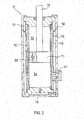
- FIG. 1 is a cross-sectional view illustrating a solenoid valve V1 according to this embodiment.
- the solenoid valve V1 includes a valve seat 2 provided in the main flow passage 1, an annular leaf valve 3 seated on or unseated from the valve seat 2 to serve as a main valve body for opening or closing the main flow passage 1, a pilot passage 4 branching from the main flow passage 1, an orifice 5 provided in the pilot passage 4, a back-pressure chamber P connected to the pilot passage 4 downstream from the orifice 5 to bias the leaf valve 3 to a closing direction using an internal pressure, a pilot valve 6 disposed in the pilot passage 4 downstream from a connection point to the back-pressure chamber P to control an internal pressure of the back-pressure chamber P, a solenoid Sol configured to adjust the valve opening pressure of the pilot valve 6, and a second orifice 7 provided between the back-pressure chamber P and the pilot valve 6.
- FIG. 2 is a cross-sectional view illustrating a shock absorber D provided with the solenoid valve V1 of FIG. 1 .
- the shock absorber D usually generates a damping force by applying resistance to a fluid passing through the main flow passage 1 in the event of expansion or contraction.
- the shock absorber D includes a cylinder 10, a piston 11 slidably inserted into the cylinder 10, a rod 12 movably inserted into the cylinder 10 and connected to the piston 11, a rod-side chamber 13 and a piston-side chamber 14 partitioned by the piston 11 inside the cylinder 10, a pipe 16 that covers the outer circumference of the cylinder 10 to form a discharge passage 15 with the cylinder 10, and an outer tube 18 that covers the outer circumference of the pipe 16 to form a reservoir 17 with the pipe 16.
- Hydraulic oil as a fluid is filled in the rod-side chamber 13, the piston-side chamber 14, and the reservoir 17 while the reservoir 17 is filled with gas in addition to the hydraulic oil.
- the fluid may include any material other than the hydraulic oil if it can exert a damping force.
- the shock absorber D further includes an inlet passage 19 that allows only for a flow of the hydraulic oil directed from the reservoir 17 to the piston-side chamber 14, and a piston passage 20 provided in the piston 11 to allow only for a flow of the hydraulic oil directed from the piston-side chamber 14 to the rod-side chamber 13.
- the discharge passage 15 causes the rod-side chamber 13 and the reservoir 17 to communicate with each other.
- the solenoid valve V1 is provided in the discharge passage 15 such that the main flow passage 1 is connected to the discharge passage 15 ( FIG. 1 ).
- the shock absorber D When the shock absorber D is operated to expand or contract, the hydraulic oil is necessarily discharged from the cylinder 10 to the reservoir 17 via the discharge passage 15. That is, the shock absorber D is a uni-flow type shock absorber in which the hydraulic oil is circulated in a unidirectional manner in the order of the piston-side chamber 14, the rod-side chamber 13, and the reservoir 17 and generates both expansive and contractive damping forces by virtue of a single solenoid valve V1.
- the cross-sectional area of the rod 12 is set to a half of the cross-sectional area of the piston 11, the amount of the hydraulic oil discharged from the cylinder 10 can be set to be the same between expansion and contraction with the same amplitude. Therefore, if the resistance to the flow caused by the solenoid valve V1 becomes constant, it is possible to set the expansive and contractive damping forces to the same value.
- the solenoid valve V1 includes a seat member 21 that is fitted to a sleeve 16a provided in an opening of the pipe 16 and has a main flow passage 1, an annular valve seat 2, and an orifice 5, a leaf valve 3 mounted to an outer circumference of the seat member 21 and seated on or unseated from the valve seat 2 to serve as a main valve body, a valve housing 22 connected to the seat member 21 to form a cavity, a pilot valve 6 inserted into the valve housing 22 movably along an axial direction, a solenoid Sol that exerts a thrust force to the pilot valve body 38 in the pilot valve 6, and a main spool 23 that is slidably mounted to an outer circumference of the valve housing 22 and abuts on the rear face of the leaf valve 3 (the right face of FIG. 1 ) to define the back-pressure chamber P in the rear face side of the leaf valve 3.
- the pilot passage 4 is formed in the seat member 21 and the inside of the valve housing 2.
- the seat member 21 includes a large-diameter basal portion 21a fitted to the sleeve 16a, a shaft portion 21b protruding to the right side of FIG. 1 from the basal portion 21a, a cavity 21c formed to penetrate through the basal portion 21a and the shaft portion 21b in an axial direction to form a part of the pilot passage 4, a second orifice 7 that is opened on the outer circumferential surface of the shaft portion 21b and communicates with the cavity 21c, an orifice 5 provided in the discharge passage 15 side upstream from the connection point of the second orifice 7 in the cavity 21c, a main flow passage 1 provided with a plurality of ports perforating through the basal portion 21a from the left end to the right end of FIG. 1 , and an annular valve seat 2 provided in an exit of the main flow passage 1 which is the right end of the basal portion 21a in FIG. 1 .
- the main flow passage 1 penetrates through the basal portion 21a.
- the opening of the main flow passage 1 provided in the left end side of the basal portion 21a in FIG. 1 communicates with the rod-side chamber 13 via the discharge passage 15 formed with the pipe 16.
- the opening of the main flow passage 1 in the right end side of the basal portion 21a in FIG. 1 communicates with the reservoir 17. Similar to the main flow passage 1, the opening of the cavity 21c in the left end side of FIG. 1 communicates with the rod-side chamber 13 via the discharge passage 15.
- a seal ring 24 is mounted to an outer circumference of the basal portion 21a of the seat member 21. As a result, a gap between the outer circumference of the basal portion 21a and the inner circumference of the sleeve 16a is sealed, so that the discharge passage 15 is prevented from communicating with the reservoir 17 via the outer circumference of the basal portion 21a.
- the annular leaf valve 3 seated on or unseated from the valve seat 2 to open or close the main flow passage 1 is stacked.
- the inner circumference of the leaf valve 3 is interposed between the basal portion 21a and the valve housing 22 and is fixed to the outer circumference of the shaft portion 21b. Therefore, the outer circumference of the leaf valve 3 can be flexed as a free end. As the leaf valve 3 is flexed by receiving a pressure applied to the front face (the left face in FIG. 1 ) from the upstream of the main flow passage 1, the leaf valve 3 is unseated from the valve seat 2 to open the main flow passage 1.
- the leaf valve 3 is a layered leaf valve obtained by stacking a plurality of annular sheets, and the number of the annular sheets may be arbitrarily set.
- a cutout orifice 3a is provided in the outer circumference of the annular sheet seated on the valve seat 2.
- the valve housing 22 having a tubular shape has an annular pilot valve seat 22a formed as a small diameter portion provided in the center inner circumference.
- the valve housing 22 is connected to the seat member 21 by inserting and screwing the shaft portion 21b of the seat member 21 into the left side from the pilot valve seat 22a in FIG. 1 .
- the inner circumference of the leaf valve 3 is interposed between the basal portion 21a of the seat member 21 and the left end of the valve housing 22 in FIG. 1 .
- the outer diameter of the valve housing 22 in the left end of FIG. 1 is formed to have a small diameter not to hinder the leaf valve 3 from being flexed.
- the inner diameter of the left-end opening of the valve housing 22 in FIG. 1 is larger than the diameter of the portion where the shaft portion 21b is screwed.
- An annular gap R is formed between the seat member 21 and the valve housing 22 when the shaft portion 21b of the seat member 21 is inserted.
- a cutout trench 22e extending in a radial direction is provided, so that the outer circumferential side of the valve housing 22 communicates with the annular gap R via the cutout trench 22e when the left end of the valve housing 22 abuts on the leaf valve 3.
- the annular gap R also communicates with the second orifice 7 formed in the shaft portion 21b of the seat member 21.
- the cutout trench 22e is a trench formed in the left end of the valve housing 22 in FIG. 1 , any other configuration such as a hole penetrating through the valve housing 22 may also be possible instead.
- the valve housing 22 is provided with a flange 22b in the outer circumference.
- the flange 22b is fitted to the inner circumference of the tube 18b provided in the opening 18a formed in the lateral side of the outer tube 18 and abuts on the step portion 18c provided in the inner circumference of the tube 18b.
- the tube 18b is provided with a thread portion (not illustrated) in the outer circumference of the edge.
- a bottomed tubular casing 25 including the solenoid Sol is screwed to the tube 18b. As the casing 25 is screwed to the tube 18b, the flange 22b of the valve housing 22 is fixed to the tube 18b, and the seat member 21 screwed to the valve housing 22 is also fixed to a predetermined position of the tube 18b.
- the valve housing 22 has a through-hole 22c provided in a radial direction in the right side of FIG. 1 from the flange 22b and the pilot valve seat 22a to cause the inside and the outside to communicate with each other.
- the outer circumference of the valve housing 22 in the right side of FIG. 1 from the through-hole 22c is provided with a flange-like sliding contact portion 22d where a failsafe valve body 42 of a tubular failsafe valve 26 is slidably mounted.
- the flange 22b is provided with a through-hole 22f penetrating in the axial direction so that the space of the right side of FIG. 1 from the flange 22b communicates with the reservoir 17 of the left side.
- the inside of the valve housing 22 communicates with the discharge passage 15 via the cavity 21c provided in the seat member 21 and with the rod-side chamber 13 via the discharge passage 15.
- the inside of the valve housing 22 communicates with the reservoir 17 via the through-holes 22c and 22f. That is, the valve housing 22 forms the pilot passage 4 branching from the main flow passage 1 and causing the rod-side chamber 13 and the reservoir 17 to communicate with each other in combination with the cavity 21c of the seat member 21.
- a tubular main spool 23 having a brim 23a in its outer circumference is slidably mounted to the outer circumference of the valve housing 22 in the left side of FIG. 1 from the flange 22b.
- a spring 27 serving as a biasing mechanism is interposed between the brim 23a of the main spool 23 and the flange 22b. The spring 27 biases the main spool 23 toward the leaf valve 3 in the left side of FIG. 1 and causes the main spool 23 to abut on the right face of FIG. 1 (the rear face of the leaf valve 3).
- the biasing mechanism may include various springs such as a coil spring or a disc spring or an elastic body such as rubber capable of exerting a resilient force against compression.
- the back-pressure chamber P is defined in the rear face of the leaf valve 3 by virtue of the main spool 23.
- the back-pressure chamber P communicates with the cavity 21c of the pilot passage 4 via the cutout trench 22e, the annular gap R, and the second orifice 7 described above.
- the cutout trench 22e, the annular gap R, and the second orifice 7 constitute a communication passage Pr.
- the internal pressure of the pilot passage 4 propagates to the back-pressure chamber P via the communication passage Pr. Since the communication passage Pr is provided with the second orifice 7, even an abrupt pressure change occurring in the pilot passage 4 does not easily propagate to the back-pressure chamber P.
- the cutout trench 22e may also serve as the second orifice.
- the seat member 21 may be provided with a simple hole that causes the annular gap R and the cavity 21c to communicate with each other.
- the annular gap R is provided to cause the second orifice 7 and the cutout trench 22e to reliably communicate with each other even when the second orifice 7 and the cutout trench 22e do not face each other in the radial direction.
- the annular gap R may be omitted if the second orifice 7 and the cutout trench 22e face each other in the radial direction.
- the internal pressure of the back-pressure chamber P is also applied to the rear face of the leaf valve 3 in addition to the biasing force for biasing the main spool 23 by the spring 27, so that the leaf valve 3 is biased toward the valve seat 2. That is, when the shock absorber D is operated to expand or contract, the internal pressure of the rod-side chamber 13 is applied to the leaf valve 3 from the front face side via the main flow passage 1, so that both the internal pressure of the back-pressure chamber P and the biasing force of the spring 27 are applied to the leaf valve 3 from the rear face side.
- the casing 25 includes a tubular portion 25a, a bottom portion 25b caulked to the opening end of the tubular portion 25a, and an annular stopper 25c fixed to the inner circumference side of the tubular portion 25a to hold a solenoid bobbin 29 where the coil 28 of the solenoid Sol is wound.
- the flange 22b of the valve housing 22 and a nonmagnetic spacer 35 are interposed using the stopper 25c and the step portion 18c of the tube 18b.
- the valve housing 22 and the seat member 21 are fixed to the shock absorber D. It is noted that, since the flange 22b is provided with a through-hole 22f, the pilot passage 4 and the reservoir 17 remain to communicate with each other.
- the solenoid Sol includes a casing 25 having a bottomed tubular shape, an annular solenoid bobbin 29 fixed to the bottom of the casing 25, where coil 28 is wound, a first stator 30 that has a bottomed tubular shape and is fitted to the inner circumference of the solenoid bobbin 29, a second stator 31 that has a tubular shape and is fitted to the inner circumference of the solenoid bobbin 29, a nonmagnetic ring 32 fitted to the inner circumference of the solenoid bobbin 29 and interposed between the first and second stators 30 and 31, a rotor 33 that has a bottomed tubular shape and is disposed in the inner circumferential side of the first stator 30, and a tubular failsafe valve 26 slidably mounted to the outer circumference of the sliding contact portion 22d of the valve housing 22 to serve as a rotor as well.
- An opening end side of the rotor 33 having a bottomed tubular shape is slidably inserted into the inner circumference of the first stator 30 to face the inside of the first stator 30.
- the dimension of the rotor 33 is set such that the bottom side face in the left side of FIG. 1 faces or is arranged in the vicinity of the inner circumference of the second stator 31 even when it enters the inside of the first stator 30 until it abuts on a nonmagnetic washer 34 provided in the bottom of the first stator 30.
- the tube of the rotor 33 is provided with a communication hole 33a formed in an axial direction, and the spaces partitioned by the first stator 30 and the rotor 33 communicate with each other via the communication hole 33a.
- a spring 36 is interposed between the rotor 33 and the first stator 30.
- the rotor 33 receives a thrust force from the spring 36 to retreat from the first stator 30.
- the spring 36 is supported by a spring bearing 37a provided in a leading end of a spring force adjustment screw 37 whose right end of FIG. 1 is screwed to the axial core of the first stator 30.
- the support position of the spring 36 may change across the left and right sides of FIG. 1 by advancing or retreating the spring force adjustment screw 37 against the first stator 30. It is noted that, according to this embodiment, manipulation of the spring force adjustment screw 37 is prohibited after the bottom portion 25b of the casing 25 is caulked to the opening end of the tubular portion 25a. However, by fixing the bottom portion 25b to the tubular portion 25a in a detachable manner, manipulation of the spring force adjustment screw 37 may be allowed even after the bottom portion 25b is fixed to the tubular portion 25a.
- the second stator 31 has a tubular shape.
- the opening end of the second stator 31 in the first stator 30 side is formed in a tapered shape such that its diameter is reduced toward the first stator 30 side.
- a magnetic flux generated when the electric current flows to the coil 28 concentrates on the right-end inner circumference side of the second stator 31.
- the shape of the left end of FIG. 1 of the nonmagnetic ring 32 interposed between the first and second stators 30 and 31 matches the shape of the tapered end of the second stator 31.
- a magnetic path is formed by the first and second stators 30 and 31, and the rotor 33.
- the rotor 33 neighboring to the first stator 30 is attracted to the second stator 31 side, so that a thrust force is applied to the rotor 33 toward the left side of FIG. 1 .
- the bottom of the rotor 33 abuts on the pilot valve body 38 of the pilot valve 6 such that the thrust force of the spring 36 is transmitted to the pilot valve body 38.
- the solenoid Sol is magnetically excited, a thrust force directed to the left side of FIG. 1 is applied to the pilot valve body 38 by virtue of the attracted rotor 33.
- the washer 34 is formed of synthetic resin or the like, it is possible to suppress impact or noise when the rotor 33 collides.
- the pilot valve body 38 includes a large-diameter portion 38a making sliding contact with the right-end inner circumference of the valve housing 22 in FIG. 1 , and a cylindrical small-diameter portion 38b extending from the left end of the large-diameter portion 38a and facing the through-hole 22c of the valve housing 22.
- the pilot valve body 38 is a flat valve for opening or closing the pilot passage 4 by seating or unseating the left-end outer circumference of the small-diameter portion 38b of FIG. 1 on or from the pilot valve seat 22a provided in the inner circumference of the valve housing 22. Since the small-diameter portion 38b is spaced from the inner circumference of the valve housing 22, the pilot valve body 38 does not block the through-hole 22c.
- a spring 40 is interposed between the left end of the large-diameter portion 38a of the pilot valve body 38 and the outer circumferential side of the pilot valve seat 22a of the valve housing 22.
- the spring 40 exerts a thrust force such that the pilot valve body 38 retreats from the pilot valve seat 22a so as to maximize the flow area of the pilot passage 4.
- the pilot valve body 38 is inserted between the springs 36 and 40 by interposing the rotor 33.
- a thrust force is applied to the pilot valve body 38 from the spring 40 so as to maximize the flow area of the pilot passage 4.
- a thrust force is applied through the rotor 33 from the spring 36 so as to reduce the flow area of the pilot passage 4.
- the pilot valve 6 includes a pilot valve seat 22a, a pilot valve body 38 seated on or unseated from the pilot valve seat 22a, and springs 36 and 40 that interpose the pilot valve body 38.
- the pilot valve 6 is provided downstream from a portion where the second orifice 7 and the cavity 21c intersect, which is the connection point where the back-pressure chamber P of the pilot passage 4 is connected.
- the springs 40 and 36 are arranged in series, it is possible to change a compression length of the spring 40 as well as a compression length of the spring 36, which is the length in a compressed state, by adjusting the support position of the spring 36 using the spring force adjustment screw 37. That is, it is possible to adjust initial loads of the springs 36 and 40 applied to the pilot valve body 38. By adjusting the initial loads, it is possible to adjust the valve opening pressure of the pilot valve 6 against the electric current amount supplied to the solenoid Sol. For the adjustment of the initial loads, any configuration other than the spring force adjustment screw 37 may also be employed if it can adjust the support position of the spring 36 in the axial direction.
- the second stator 31 of the solenoid Sol protrudes to the left side in FIG. 1 from the solenoid bobbin 29.
- a spacer 35 is fitted to the left-end outer circumference of the second stator 31.
- the spacer 35 has a tubular shape and has a flange 35a in the right-end inner circumference.
- the inner circumference of the flange 35a is fitted to the outer circumference of the second stator 31.
- the spacer 35 is also fitted to the inner circumference of the tube 18b provided in the outer tube 18.
- a gap between the spacer 35 and the tube 18b is sealed with a seal ring 41 mounted to the outer circumference of the spacer 35.
- the failsafe valve 26 includes a failsafe valve body 42 slidably mounted to the outer circumference of the sliding contact portion 22d of the valve housing 22 and a spring 43 interposed between the failsafe valve body 42 and the flange 35a of the spacer 35.
- the failsafe valve body 42 having a tubular shape includes a brim 42a provided in the outer circumference side, an annular protrusion 42b facing the right-end face of the flange 22b of the valve housing 22 in FIG. 1 , an orifice passage 42c that causes the inner and outer circumferences of the failsafe valve body 42 to communicate with each other, and a communication hole 42d that is opened from the right end of FIG. 1 and communicates with the orifice passage 42c.
- a spring 43 is interposed between the brim 42a and the flange 35a of the spacer 35, so that the failsafe valve body 42 receives a thrust force exerted toward the flange 22b side of the valve housing 22 from the spring 43 at all times.
- the right end of the failsafe valve body 42 faces the left end of the second stator 31, and a magnetic path is formed by the second stator 31, the failsafe valve body 42, the valve housing 22, the tube 18b, and the casing 25.
- the failsafe valve body 42 is attracted to the second stator 31, so that a thrust force is exerted to the failsafe valve body 42 toward the right side of FIG. 1 . If the electric current supplied to the solenoid Sol exceeds a predetermined value I1, the thrust force applied to the failsafe valve body 42 from the solenoid Sol exceeds the thrust force of the spring 43. As a result, the failsafe valve body 42 abuts on the second stator 31, and the pilot passage 4 is fully opened.
- the thrust force applied to the failsafe valve body 42 from the solenoid Sol is weaker than the thrust force of the spring 43.
- the failsafe valve body 42 moves to a failure position where the annular protrusion 42b abuts on the flange 22b of the valve housing 22 so that the flow area of the pilot passage 4 is restricted.
- the orifice passage 42c of the failsafe valve body 42 faces the pilot passage 4, so that the pilot passage 4 communicates only via the orifice passage 42c. Therefore, the flow area of the pilot passage 4 is restricted by the flow area of the orifice passage 42c.
- the failsafe valve 26 moves to an open position where the pilot passage 4 is opened. If the electric current supplied to the solenoid Sol is equal to or lower than the predetermined value I1, the failsafe valve 26 moves to the failure position where the pilot passage 4 communicates only via the orifice passage 42c.
- the communication hole 42d is not blocked by the end portion of the second stator 31 and remains in the communication state even when the failsafe valve body 42 abuts on the second stator 31.
- the space where the rotor 33 is housed is not blocked.
- the pilot valve body 38 is not locked, and its movement is not prohibited.
- the electric current is supplied to the solenoid Sol ranging from the electric current value I2 higher than the predetermined value I1 to the electric current value I3.
- the electric current supplied to the solenoid Sol stops.
- the pilot valve body 38 of the pilot valve 6 is pressed to the pilot valve seat 22a resisting to the biasing force of the spring 40 by virtue of the thrust force of the solenoid Sol and the biasing force of the spring 36.
- the pilot valve 6 When the pressure of the upstream side of the pilot passage 4 is applied to the pilot valve body 38, and a resultant force between the force of unseating the pilot valve body 38 from the pilot valve seat 22a and the biasing force of the spring 40 exceeds a resultant force between the thrust force of the solenoid Sol and the biasing force of the spring 36, the pilot valve 6 is opened, so that the pilot passage 4 is opened accordingly. That is, when the pressure of the upstream side of the pilot passage 4 reaches the valve opening pressure, the pilot valve 6 is opened, so that the pilot passage 4 is opened accordingly.
- the solenoid valve V1 when the solenoid valve V1 is operated normally, the electric current ranging between the electric current values I2 and I3 higher than the predetermined value I1 is supplied to the solenoid Sol. As a result, the valve opening pressure of the pilot valve 6 is controlled, and the failsafe valve 26 causes the pilot passage 4 to remain in the opened state.
- the upper limitation I3 of the electric current value for a normal operation is defined by the specification of the solenoid Sol.
- the lower limitation of the electric current value for a normal operation is set to the electric current value I2 higher than the predetermined value I1 where the failsafe valve 26 switches to the failure position.
- Such a setting is to prevent the failsafe valve 26 from switching to the failure position when a normal operation is desired due to a change of the electric current supplied to the solenoid Sol or a shortage of the electric current caused by fluctuation of a power voltage or noise. Therefore, a margin is provided between the predetermined value I1 and the lower limitation I2 of the electric current value for a normal operation such that an erroneous operation can be prevented.
- the valve opening pressure in the main valve including the leaf valve 3 and the valve seat 2 is adjusted by the electric current amount supplied to the solenoid Sol.
- the shock absorber D expands, the internal pressure of the rod-side chamber 13 can be controlled to the valve opening pressure of the main valve including the leaf valve 3 and the valve seat 2.
- the shock absorber D contracts, the internal pressure of the cylinder 10 can be controlled to the valve opening pressure of the main valve including the leaf valve 3 and the valve seat 2.
- the shock absorber D When the electric current supplied to the solenoid Sol is set to the electric current value I2, the valve opening pressure of the pilot valve 6 is minimized, and the valve opening pressure of the main valve is also minimized. In this case, the shock absorber D generates a minimum soft damping force.
- the electric current supplied to the solenoid Sol is set to the electric current value I3
- the valve opening pressure of the pilot valve 6 is maximized, so that the valve opening pressure of the main valve is maximized.
- the shock absorber D generates a maximum hard damping force. As a result, it is possible to adjust the damping force of the shock absorber D steplessly from the soft level to the hard level by changing the electric current amount supplied to the solenoid Sol.
- the solenoid valve V1 is provided with the second orifice 7 between the pilot valve 6 and the back-pressure chamber P, a delay is generated in the valve opening response of the pilot valve 6, so that, even when the internal pressure of the pilot passage 4 between the orifice 5 and the pilot valve 6 instantaneously becomes equal to or higher than the valve opening pressure, the second orifice 7 prevents such an instantaneous pressure rise from propagating to the back-pressure chamber P. Therefore, it is possible to suppress the influence on the valve opening pressure of the main valve including the leaf valve 3 and the valve seat 2 and stabilize the opening level of the main flow passage 1 of the leaf valve 3. As a result, it is possible to prevent an abrupt change of the damping force generated by the shock absorber D.
- the solenoid valve V1 is used in the shock absorber D in this manner, it is possible to suppress vibration or abnormal noise in a chassis. Therefore, it is possible to improve a vehicle ride quality without making passengers feel discomfort.
- pilot passage 4 causes the rod-side chamber 13 and the reservoir 17 to communicate with each other only via the orifice 5 without the second orifice 7
- resistance caused by the second orifice 7 is not added to the pressure loss generated by the main valve. Therefore, it is possible to suppress degradation of controllability of the damping force of the shock absorber D.
- FIG. 1 which is the contact surface of the valve seat 2 where the leaf valve 3 is seated or unseated, is roughened.
- the leaf valve 3 is prevented from adhering to the valve seat 2 and make the leaf valve 3 easy to open. Therefore, even when a slight pressure change occurs in the back-pressure chamber P due to an opening delay of the pilot valve 6, it is possible to alleviate the delay of the valve open timing of the main valve and further alleviate an abrupt change of the damping force of the shock absorber D.
- the pilot valve 6 opens the pilot passage 4, and the failsafe valve 26 restricts the flow area of the pilot passage 4 to the flow area of the orifice passage 42c.
- the internal pressure of the back-pressure chamber P is defined by resistances of the orifice 5, the second orifice 7, and the orifice passage 42c.
- the failsafe valve 26 is in the open position, and only the pilot valve 6 is operated. Therefore, it is possible to independently adjust the valve opening pressure of the pilot valve 6 by excluding influence of the failsafe valve 26. In addition, during a failure, the flow area is restricted only by the failsafe valve 26 without restricting the pilot passage 4 using the pilot valve 6.
- the solenoid valve V1 according to the first embodiment is provided with the second orifice 7 in the communication passage Pr that connects the back-pressure chamber P and the pilot passage 4.
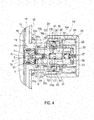
- a solenoid valve V2 according to this embodiment is provided with a second orifice 50 between the orifice 5 and the pilot valve 6 in the pilot passage 4 as illustrated in FIG. 4 .
- the seat member 51 of the solenoid valve V2 includes a basal portion 51a fitted to the sleeve 16a with a large diameter, a shaft portion 51b protruding to the right side of FIG. 4 from the basal portion 51a, a cavity 51c formed to penetrate through the basal portion 51a and the shaft portion 51b in an axial direction to form a part of the pilot passage 4, a penetrating hole 51d that is opened from the outer circumference of the shaft portion 51b and communicates with the cavity 51c, an orifice 5 provided in the discharge passage 15 side upstream from the connection point of the penetrating hole 51d in the cavity 51c, a main flow passage 1 including a plurality of ports penetrating through the basal portion 51a from the left end of FIG. 4 to the right end, and an annular valve seat 2 provided in the outer circumference side of the exit of the main flow passage 1 which is the right end of FIG. 5 of the basal portion 51a.
- a plug 52 having the second orifice 50 is screwed to the right-end inner circumference of FIG. 4 of the shaft portion 51b of the seat member 51.
- the pressure between the orifice 5 and the second orifice 50 is guided to the back-pressure chamber P.
- the orifice 5 and the second orifice 50 are arranged in series between the pilot valve 6 and the rod-side chamber 13 in the upstream side.
- the internal pressure of the back-pressure chamber P is controlled by the valve opening pressure by adjusting the valve opening pressure of the pilot valve 6.
- this abrupt pressure change is suppressed from propagating to the back-pressure chamber P because the second orifice 50 is arranged between the back-pressure chamber P and the pilot valve 6.
- the orifice 5 and the second orifice 50 are arranged in series in the pilot passage 4 connected to the pilot valve 6, the flow rate passing through the pilot passage 4 is reduced. As a result, it is possible to reduce a pressure rise level in the pilot passage 4 between the second orifice 50 and the pilot valve 6 generated by an opening delay of the pilot valve 6. Accordingly, it is possible to further reduce influence on the valve opening pressure of the main valve.
- shock absorber D is provided with the solenoid valve V2, it is possible to alleviate an abrupt change of the damping force of the shock absorber D. Therefore, it is possible to suppress vibration of a chassis or abnormal noise and improve a vehicle ride quality without making passengers feel discomfort.
- the main valve body of the main valve is a thin leaf valve 3
- valve bodies such as a spool or a poppet valve may be employed as the main valve body without limiting to the leaf valve if it can adjust the valve opening pressure with the internal pressure of the back-pressure chamber P applied to the rear face of the main valve body.
- the failsafe valve 26 has the orifice passage 42c that faces the pilot passage 4 to restrict the pilot passage 4 as it switches to the failure position, it is possible to simplify the structure of the solenoid valve V1 without necessity of arranging a subsidiary flow passage having a separate orifice in parallel in the pilot passage 4.
- a subsidiary flow passage having an orifice may be provided in parallel with the pilot passage 4 such that the pilot passage 4 is perfectly blocked by the failsafe valve 26, and only the subsidiary flow passage works in the event of a failure.
- valves such as a choke valve may also be employed to restrict the flow area of the pilot passage 4 by the failsafe valve 26 instead of the orifice passage 42c.
- the failsafe valve 26 may be omitted.
- other types of solenoids Sol can be employed without limiting to the configuration, the structure, and the magnetic path described above if it can drive the pilot valve 6.
Abstract
Description
- This invention relates to a solenoid valve.
- It is known that a solenoid valve is used as a controllable damping valve capable of controlling a damping force of a shock absorber interposed between a chassis and an axle of a vehicle. In
JP 2009-222136 A - A secondary pressure downstream from the orifice in the pilot passage is introduced into the back-pressure chamber, and the main valve body is pressed by the secondary pressure. Since the pilot valve is provided downstream from the back-pressure chamber, the secondary pressure introduced into the back-pressure chamber is controlled by the valve opening pressure of the pilot valve by adjusting the valve opening pressure of the pilot valve using a thrust force of the solenoid.
- The secondary pressure is applied to the rear face of the main valve body to exert a force such that the main valve body is pressed toward the valve seat side. A pressure is applied from the upstream of the main flow passage to the front face of the main valve body to exert a force such that the main valve body is flexed and is unseated from the valve seat. Therefore, the main valve body is opened when the force of unseating the main valve body from the valve seat by virtue of the pressure from the upstream side of the main flow passage exceeds the force of pressing the main valve body to the valve seat by virtue of the secondary pressure.
- That is, it is possible to adjust the valve opening pressure of the main valve body by controlling the secondary pressure. Therefore, the solenoid valve can change resistance to the liquid flow passing through the main flow passage by adjusting the valve opening pressure of the pilot valve using the solenoid so that a desired damping force can be generated in the shock absorber.
- The solenoid valve of the prior art described above is provided with a spring for biasing the pilot valve to open the pilot passage. The solenoid exerts a thrust force for closing the pilot passage toward the pilot valve. That is, the valve opening pressure of the pilot valve is adjusted by changing the electric current amount applied to the solenoid.
- As the pilot valve is opened, the solenoid valve releases the pressure of the upstream side of the pilot passage to the reservoir. As a result, the back-pressure chamber is controlled by the valve opening pressure of the pilot valve. However, since a delay occurs when the pilot valve is opened from the closed state, the internal pressure of the back-pressure chamber rises over the valve opening pressure of the pilot valve only for an instant. Then, as the pilot valve is opened, and the pressure is released, the pressure of the back-pressure chamber decreases to the valve opening pressure.
- In this manner, since the opening level of the main flow passage of the main valve body abruptly changes due to an abrupt change of the internal pressure of the back-pressure chamber at the time of opening the pilot valve, the damping force generated by the shock absorber also abruptly changes. As a result, vibration of a chassis or abnormal noise in a cabin may be generated.
- In view of the aforementioned problems, it is therefore an object of this invention to provide a solenoid valve capable of alleviating an abrupt change of the damping force.
- According to one aspect of the present invention, a solenoid valve includes a valve seat provided in a main flow passage, a main valve body seated on or unseated from the valve seat to open or close the main flow passage, a pilot passage that branches from the main flow passage, an orifice provided in the pilot passage, a back-pressure chamber connected to the pilot passage downstream from the orifice, the back-pressure chamber being configured to bias the main valve body to a closing direction by virtue of an internal pressure, a pilot valve disposed in the pilot passage downstream from a connection point to the back-pressure chamber, the pilot valve being configured to control an internal pressure of the back-pressure chamber, a solenoid configured to control a valve opening pressure of the pilot valve, and a second orifice provided between the back-pressure chamber and the pilot valve.
-
-
FIG. 1 is a cross-sectional view illustrating a solenoid valve according to a first embodiment of this invention; -
FIG. 2 is a cross-sectional view illustrating a shock absorber provided with the solenoid valve ofFIG. 1 ; -
FIG. 3 is a diagram illustrating a relationship between the electric current supplied to the solenoid and the damping force of the shock absorber provided with the solenoid valve; and -
FIG. 4 is a cross-sectional view illustrating the solenoid valve according to a second embodiment of this invention. - A description will now be made for embodiments of this invention with reference to the accompanying drawings.
- First, a first embodiment will be described.
-
FIG. 1 is a cross-sectional view illustrating a solenoid valve V1 according to this embodiment. The solenoid valve V1 includes avalve seat 2 provided in themain flow passage 1, anannular leaf valve 3 seated on or unseated from thevalve seat 2 to serve as a main valve body for opening or closing themain flow passage 1, apilot passage 4 branching from themain flow passage 1, anorifice 5 provided in thepilot passage 4, a back-pressure chamber P connected to thepilot passage 4 downstream from theorifice 5 to bias theleaf valve 3 to a closing direction using an internal pressure, apilot valve 6 disposed in thepilot passage 4 downstream from a connection point to the back-pressure chamber P to control an internal pressure of the back-pressure chamber P, a solenoid Sol configured to adjust the valve opening pressure of thepilot valve 6, and asecond orifice 7 provided between the back-pressure chamber P and thepilot valve 6. -
FIG. 2 is a cross-sectional view illustrating a shock absorber D provided with the solenoid valve V1 ofFIG. 1 . The shock absorber D usually generates a damping force by applying resistance to a fluid passing through themain flow passage 1 in the event of expansion or contraction. - The shock absorber D includes a
cylinder 10, apiston 11 slidably inserted into thecylinder 10, arod 12 movably inserted into thecylinder 10 and connected to thepiston 11, a rod-side chamber 13 and a piston-side chamber 14 partitioned by thepiston 11 inside thecylinder 10, apipe 16 that covers the outer circumference of thecylinder 10 to form adischarge passage 15 with thecylinder 10, and anouter tube 18 that covers the outer circumference of thepipe 16 to form areservoir 17 with thepipe 16. - Hydraulic oil as a fluid is filled in the rod-
side chamber 13, the piston-side chamber 14, and thereservoir 17 while thereservoir 17 is filled with gas in addition to the hydraulic oil. It is noted that the fluid may include any material other than the hydraulic oil if it can exert a damping force. - The shock absorber D further includes an
inlet passage 19 that allows only for a flow of the hydraulic oil directed from thereservoir 17 to the piston-side chamber 14, and apiston passage 20 provided in thepiston 11 to allow only for a flow of the hydraulic oil directed from the piston-side chamber 14 to the rod-side chamber 13. Thedischarge passage 15 causes the rod-side chamber 13 and thereservoir 17 to communicate with each other. The solenoid valve V1 is provided in thedischarge passage 15 such that themain flow passage 1 is connected to the discharge passage 15 (FIG. 1 ). - When the shock absorber D is operated to contract, the
piston 11 moves downward inFIG. 2 so that the piston-side chamber 14 is compressed, and the hydraulic oil of the piston-side chamber 14 moves to the rod-side chamber 13 via thepiston passage 20. During the contraction, since therod 12 intrudes into thecylinder 10, the amount of the hydraulic oil becomes excessive as much as the volume of the rod intruding into thecylinder 10. Therefore, the excessive hydraulic oil is extruded from thecylinder 10 and is discharged to thereservoir 17 via thedischarge passage 15. Since the shock absorber D applies resistance to the flow of the hydraulic oil moving to thereservoir 17 via thedischarge passage 15 by virtue of the solenoid valve V1, the internal pressure of thecylinder 10 increases, and a contractive damping force is exerted. - When the shock absorber D is operated to expand, the
piston 11 moves upward inFIG. 2 , so that the rod-side chamber 13 is compressed, and the hydraulic oil of the rod-side chamber 13 moves to thereservoir 17 via thedischarge passage 15. During the expansion, thepiston 11 moves upward, and the volume of the piston-side chamber 14 increases. Therefore, the hydraulic oil is supplied from thereservoir 17 via theinlet passage 19 as much as the volume increases. Since the shock absorber D applies resistance to the flow of the hydraulic oil moving to thereservoir 17 via thedischarge passage 15 by virtue of the solenoid valve V1, the internal pressure of the rod-side chamber 13 increases, and an expansive damping force is exerted. - When the shock absorber D is operated to expand or contract, the hydraulic oil is necessarily discharged from the
cylinder 10 to thereservoir 17 via thedischarge passage 15. That is, the shock absorber D is a uni-flow type shock absorber in which the hydraulic oil is circulated in a unidirectional manner in the order of the piston-side chamber 14, the rod-side chamber 13, and thereservoir 17 and generates both expansive and contractive damping forces by virtue of a single solenoid valve V1. - It is noted that, if the cross-sectional area of the
rod 12 is set to a half of the cross-sectional area of thepiston 11, the amount of the hydraulic oil discharged from thecylinder 10 can be set to be the same between expansion and contraction with the same amplitude. Therefore, if the resistance to the flow caused by the solenoid valve V1 becomes constant, it is possible to set the expansive and contractive damping forces to the same value. - The solenoid valve V1 includes a
seat member 21 that is fitted to asleeve 16a provided in an opening of thepipe 16 and has amain flow passage 1, anannular valve seat 2, and anorifice 5, aleaf valve 3 mounted to an outer circumference of theseat member 21 and seated on or unseated from thevalve seat 2 to serve as a main valve body, avalve housing 22 connected to theseat member 21 to form a cavity, apilot valve 6 inserted into thevalve housing 22 movably along an axial direction, a solenoid Sol that exerts a thrust force to thepilot valve body 38 in thepilot valve 6, and amain spool 23 that is slidably mounted to an outer circumference of thevalve housing 22 and abuts on the rear face of the leaf valve 3 (the right face ofFIG. 1 ) to define the back-pressure chamber P in the rear face side of theleaf valve 3. Thepilot passage 4 is formed in theseat member 21 and the inside of thevalve housing 2. - The
seat member 21 includes a large-diameterbasal portion 21a fitted to thesleeve 16a, ashaft portion 21b protruding to the right side ofFIG. 1 from thebasal portion 21a, a cavity 21c formed to penetrate through thebasal portion 21a and theshaft portion 21b in an axial direction to form a part of thepilot passage 4, asecond orifice 7 that is opened on the outer circumferential surface of theshaft portion 21b and communicates with the cavity 21c, anorifice 5 provided in thedischarge passage 15 side upstream from the connection point of thesecond orifice 7 in the cavity 21c, amain flow passage 1 provided with a plurality of ports perforating through thebasal portion 21a from the left end to the right end ofFIG. 1 , and anannular valve seat 2 provided in an exit of themain flow passage 1 which is the right end of thebasal portion 21a inFIG. 1 . - The
main flow passage 1 penetrates through thebasal portion 21a. The opening of themain flow passage 1 provided in the left end side of thebasal portion 21a inFIG. 1 communicates with the rod-side chamber 13 via thedischarge passage 15 formed with thepipe 16. The opening of themain flow passage 1 in the right end side of thebasal portion 21a inFIG. 1 communicates with thereservoir 17. Similar to themain flow passage 1, the opening of the cavity 21c in the left end side ofFIG. 1 communicates with the rod-side chamber 13 via thedischarge passage 15. - It is noted that a
seal ring 24 is mounted to an outer circumference of thebasal portion 21a of theseat member 21. As a result, a gap between the outer circumference of thebasal portion 21a and the inner circumference of thesleeve 16a is sealed, so that thedischarge passage 15 is prevented from communicating with thereservoir 17 via the outer circumference of thebasal portion 21a. - In the right end of the
basal portion 21a of theseat member 21 inFIG. 1 , theannular leaf valve 3 seated on or unseated from thevalve seat 2 to open or close themain flow passage 1 is stacked. The inner circumference of theleaf valve 3 is interposed between thebasal portion 21a and thevalve housing 22 and is fixed to the outer circumference of theshaft portion 21b. Therefore, the outer circumference of theleaf valve 3 can be flexed as a free end. As theleaf valve 3 is flexed by receiving a pressure applied to the front face (the left face inFIG. 1 ) from the upstream of themain flow passage 1, theleaf valve 3 is unseated from thevalve seat 2 to open themain flow passage 1. It is noted that theleaf valve 3 is a layered leaf valve obtained by stacking a plurality of annular sheets, and the number of the annular sheets may be arbitrarily set. In addition, acutout orifice 3a is provided in the outer circumference of the annular sheet seated on thevalve seat 2. - The
valve housing 22 having a tubular shape has an annularpilot valve seat 22a formed as a small diameter portion provided in the center inner circumference. Thevalve housing 22 is connected to theseat member 21 by inserting and screwing theshaft portion 21b of theseat member 21 into the left side from thepilot valve seat 22a inFIG. 1 . As a result, the inner circumference of theleaf valve 3 is interposed between thebasal portion 21a of theseat member 21 and the left end of thevalve housing 22 inFIG. 1 . It is noted that the outer diameter of thevalve housing 22 in the left end ofFIG. 1 is formed to have a small diameter not to hinder theleaf valve 3 from being flexed. - The inner diameter of the left-end opening of the
valve housing 22 inFIG. 1 is larger than the diameter of the portion where theshaft portion 21b is screwed. An annular gap R is formed between theseat member 21 and thevalve housing 22 when theshaft portion 21b of theseat member 21 is inserted. In the left end of thevalve housing 22 ofFIG. 1 , acutout trench 22e extending in a radial direction is provided, so that the outer circumferential side of thevalve housing 22 communicates with the annular gap R via thecutout trench 22e when the left end of thevalve housing 22 abuts on theleaf valve 3. The annular gap R also communicates with thesecond orifice 7 formed in theshaft portion 21b of theseat member 21. It is noted that, although thecutout trench 22e is a trench formed in the left end of thevalve housing 22 inFIG. 1 , any other configuration such as a hole penetrating through thevalve housing 22 may also be possible instead. - The
valve housing 22 is provided with aflange 22b in the outer circumference. Theflange 22b is fitted to the inner circumference of thetube 18b provided in theopening 18a formed in the lateral side of theouter tube 18 and abuts on thestep portion 18c provided in the inner circumference of thetube 18b. It is noted that thetube 18b is provided with a thread portion (not illustrated) in the outer circumference of the edge. A bottomedtubular casing 25 including the solenoid Sol is screwed to thetube 18b. As thecasing 25 is screwed to thetube 18b, theflange 22b of thevalve housing 22 is fixed to thetube 18b, and theseat member 21 screwed to thevalve housing 22 is also fixed to a predetermined position of thetube 18b. - It is noted that a gap between the
sleeve 16a and theseat member 21 is sealed by theseal ring 24 mounted in the outer circumference of theseat member 21, so that thebasal portion 21a of theseat member 21 is inserted into thesleeve 16a with a margin. As a result, even when there is a deviation of the axial center between thetube 18a and thesleeve 16a, it is possible to easily fit theflange 22b of thevalve housing 22 into thetube 18b. - The
valve housing 22 has a through-hole 22c provided in a radial direction in the right side ofFIG. 1 from theflange 22b and thepilot valve seat 22a to cause the inside and the outside to communicate with each other. The outer circumference of thevalve housing 22 in the right side ofFIG. 1 from the through-hole 22c is provided with a flange-like slidingcontact portion 22d where afailsafe valve body 42 of a tubularfailsafe valve 26 is slidably mounted. Theflange 22b is provided with a through-hole 22f penetrating in the axial direction so that the space of the right side ofFIG. 1 from theflange 22b communicates with thereservoir 17 of the left side. - The inside of the
valve housing 22 communicates with thedischarge passage 15 via the cavity 21c provided in theseat member 21 and with the rod-side chamber 13 via thedischarge passage 15. The inside of thevalve housing 22 communicates with thereservoir 17 via the through-holes 22c and 22f. That is, thevalve housing 22 forms thepilot passage 4 branching from themain flow passage 1 and causing the rod-side chamber 13 and thereservoir 17 to communicate with each other in combination with the cavity 21c of theseat member 21. - A tubular
main spool 23 having abrim 23a in its outer circumference is slidably mounted to the outer circumference of thevalve housing 22 in the left side ofFIG. 1 from theflange 22b. Aspring 27 serving as a biasing mechanism is interposed between thebrim 23a of themain spool 23 and theflange 22b. Thespring 27 biases themain spool 23 toward theleaf valve 3 in the left side ofFIG. 1 and causes themain spool 23 to abut on the right face ofFIG. 1 (the rear face of the leaf valve 3). It is noted that the biasing mechanism may include various springs such as a coil spring or a disc spring or an elastic body such as rubber capable of exerting a resilient force against compression. - While the
main spool 23 abuts on the rear face of theleaf valve 3, the back-pressure chamber P is defined in the rear face of theleaf valve 3 by virtue of themain spool 23. The back-pressure chamber P communicates with the cavity 21c of thepilot passage 4 via thecutout trench 22e, the annular gap R, and thesecond orifice 7 described above. Thecutout trench 22e, the annular gap R, and thesecond orifice 7 constitute a communication passage Pr. The internal pressure of thepilot passage 4 propagates to the back-pressure chamber P via the communication passage Pr. Since the communication passage Pr is provided with thesecond orifice 7, even an abrupt pressure change occurring in thepilot passage 4 does not easily propagate to the back-pressure chamber P. - It is noted that the
cutout trench 22e may also serve as the second orifice. In this case, theseat member 21 may be provided with a simple hole that causes the annular gap R and the cavity 21c to communicate with each other. In addition, the annular gap R is provided to cause thesecond orifice 7 and thecutout trench 22e to reliably communicate with each other even when thesecond orifice 7 and thecutout trench 22e do not face each other in the radial direction. However, the annular gap R may be omitted if thesecond orifice 7 and thecutout trench 22e face each other in the radial direction. - The internal pressure of the back-pressure chamber P is also applied to the rear face of the
leaf valve 3 in addition to the biasing force for biasing themain spool 23 by thespring 27, so that theleaf valve 3 is biased toward thevalve seat 2. That is, when the shock absorber D is operated to expand or contract, the internal pressure of the rod-side chamber 13 is applied to theleaf valve 3 from the front face side via themain flow passage 1, so that both the internal pressure of the back-pressure chamber P and the biasing force of thespring 27 are applied to theleaf valve 3 from the rear face side. - In this case, if the force of flexing the outer circumference of the
leaf valve 3 toward the right side ofFIG. 1 by virtue of the internal pressure of the rod-side chamber 13 exceeds a sum of flexural rigidity of theleaf valve 3, the force obtained by multiplying the internal pressure of the back-pressure chamber P by the pressure-receiving area of theleaf valve 3 for receiving the internal pressure, and the biasing force of thespring 27, thespring 27 is compressed, themain spool 23 retreats from thebasal portion 21a, and theleaf valve 3 is flexed, so that themain flow passage 1 is opened. - The
casing 25 includes atubular portion 25a, abottom portion 25b caulked to the opening end of thetubular portion 25a, and anannular stopper 25c fixed to the inner circumference side of thetubular portion 25a to hold asolenoid bobbin 29 where thecoil 28 of the solenoid Sol is wound. Theflange 22b of thevalve housing 22 and anonmagnetic spacer 35 are interposed using thestopper 25c and thestep portion 18c of thetube 18b. As a result, thevalve housing 22 and theseat member 21 are fixed to the shock absorber D. It is noted that, since theflange 22b is provided with a through-hole 22f, thepilot passage 4 and thereservoir 17 remain to communicate with each other. - The solenoid Sol includes a
casing 25 having a bottomed tubular shape, anannular solenoid bobbin 29 fixed to the bottom of thecasing 25, wherecoil 28 is wound, afirst stator 30 that has a bottomed tubular shape and is fitted to the inner circumference of thesolenoid bobbin 29, asecond stator 31 that has a tubular shape and is fitted to the inner circumference of thesolenoid bobbin 29, anonmagnetic ring 32 fitted to the inner circumference of thesolenoid bobbin 29 and interposed between the first andsecond stators rotor 33 that has a bottomed tubular shape and is disposed in the inner circumferential side of thefirst stator 30, and a tubularfailsafe valve 26 slidably mounted to the outer circumference of the slidingcontact portion 22d of thevalve housing 22 to serve as a rotor as well. - An opening end side of the
rotor 33 having a bottomed tubular shape is slidably inserted into the inner circumference of thefirst stator 30 to face the inside of thefirst stator 30. The dimension of therotor 33 is set such that the bottom side face in the left side ofFIG. 1 faces or is arranged in the vicinity of the inner circumference of thesecond stator 31 even when it enters the inside of thefirst stator 30 until it abuts on anonmagnetic washer 34 provided in the bottom of thefirst stator 30. The tube of therotor 33 is provided with acommunication hole 33a formed in an axial direction, and the spaces partitioned by thefirst stator 30 and therotor 33 communicate with each other via thecommunication hole 33a. - A
spring 36 is interposed between therotor 33 and thefirst stator 30. Therotor 33 receives a thrust force from thespring 36 to retreat from thefirst stator 30. Thespring 36 is supported by aspring bearing 37a provided in a leading end of a springforce adjustment screw 37 whose right end ofFIG. 1 is screwed to the axial core of thefirst stator 30. The support position of thespring 36 may change across the left and right sides ofFIG. 1 by advancing or retreating the springforce adjustment screw 37 against thefirst stator 30. It is noted that, according to this embodiment, manipulation of the springforce adjustment screw 37 is prohibited after thebottom portion 25b of thecasing 25 is caulked to the opening end of thetubular portion 25a. However, by fixing thebottom portion 25b to thetubular portion 25a in a detachable manner, manipulation of the springforce adjustment screw 37 may be allowed even after thebottom portion 25b is fixed to thetubular portion 25a. - The
second stator 31 has a tubular shape. The opening end of thesecond stator 31 in thefirst stator 30 side is formed in a tapered shape such that its diameter is reduced toward thefirst stator 30 side. As a result, a magnetic flux generated when the electric current flows to thecoil 28 concentrates on the right-end inner circumference side of thesecond stator 31. The shape of the left end ofFIG. 1 of thenonmagnetic ring 32 interposed between the first andsecond stators second stator 31. - In the solenoid Sol, a magnetic path is formed by the first and
second stators rotor 33. As thecoil 28 is magnetically excited, therotor 33 neighboring to thefirst stator 30 is attracted to thesecond stator 31 side, so that a thrust force is applied to therotor 33 toward the left side ofFIG. 1 . - The bottom of the
rotor 33 abuts on thepilot valve body 38 of thepilot valve 6 such that the thrust force of thespring 36 is transmitted to thepilot valve body 38. When the solenoid Sol is magnetically excited, a thrust force directed to the left side ofFIG. 1 is applied to thepilot valve body 38 by virtue of the attractedrotor 33. It is noted that, if thewasher 34 is formed of synthetic resin or the like, it is possible to suppress impact or noise when therotor 33 collides. - The
pilot valve body 38 includes a large-diameter portion 38a making sliding contact with the right-end inner circumference of thevalve housing 22 inFIG. 1 , and a cylindrical small-diameter portion 38b extending from the left end of the large-diameter portion 38a and facing the through-hole 22c of thevalve housing 22. Thepilot valve body 38 is a flat valve for opening or closing thepilot passage 4 by seating or unseating the left-end outer circumference of the small-diameter portion 38b ofFIG. 1 on or from thepilot valve seat 22a provided in the inner circumference of thevalve housing 22. Since the small-diameter portion 38b is spaced from the inner circumference of thevalve housing 22, thepilot valve body 38 does not block the through-hole 22c. - A
spring 40 is interposed between the left end of the large-diameter portion 38a of thepilot valve body 38 and the outer circumferential side of thepilot valve seat 22a of thevalve housing 22. Thespring 40 exerts a thrust force such that thepilot valve body 38 retreats from thepilot valve seat 22a so as to maximize the flow area of thepilot passage 4. - The
pilot valve body 38 is inserted between thesprings rotor 33. A thrust force is applied to thepilot valve body 38 from thespring 40 so as to maximize the flow area of thepilot passage 4. In addition, a thrust force is applied through therotor 33 from thespring 36 so as to reduce the flow area of thepilot passage 4. - While no electric current flows to the
coil 28 of the solenoid Sol, the thrust force of thespring 40 is equal to or stronger than that of thespring 36, and therotor 33 is forcibly inserted into thefirst stator 30 until therotor 33 abuts on thewasher 34. As a result, thepilot valve body 38 retreats from thepilot valve seat 22a to the position where the flow area of thepilot passage 4 is maximized. While an electric current flows to thecoil 28 of the solenoid Sol, therotor 33 is attracted, so that thepilot valve body 38 is seated on thepilot valve seat 22a resisting to the biasing force of thespring 40. That is, by adjusting the electric current amount flowing to the solenoid Sol, it is possible to adjust the thrust force applied to thepilot valve body 38 and control the valve opening pressure of thepilot valve 6. - The
pilot valve 6 includes apilot valve seat 22a, apilot valve body 38 seated on or unseated from thepilot valve seat 22a, and springs 36 and 40 that interpose thepilot valve body 38. Thepilot valve 6 is provided downstream from a portion where thesecond orifice 7 and the cavity 21c intersect, which is the connection point where the back-pressure chamber P of thepilot passage 4 is connected. - Since the
springs spring 40 as well as a compression length of thespring 36, which is the length in a compressed state, by adjusting the support position of thespring 36 using the springforce adjustment screw 37. That is, it is possible to adjust initial loads of thesprings pilot valve body 38. By adjusting the initial loads, it is possible to adjust the valve opening pressure of thepilot valve 6 against the electric current amount supplied to the solenoid Sol. For the adjustment of the initial loads, any configuration other than the springforce adjustment screw 37 may also be employed if it can adjust the support position of thespring 36 in the axial direction. - The
second stator 31 of the solenoid Sol protrudes to the left side inFIG. 1 from thesolenoid bobbin 29. Aspacer 35 is fitted to the left-end outer circumference of thesecond stator 31. Thespacer 35 has a tubular shape and has aflange 35a in the right-end inner circumference. The inner circumference of theflange 35a is fitted to the outer circumference of thesecond stator 31. Thespacer 35 is also fitted to the inner circumference of thetube 18b provided in theouter tube 18. A gap between thespacer 35 and thetube 18b is sealed with aseal ring 41 mounted to the outer circumference of thespacer 35. - The
failsafe valve 26 includes afailsafe valve body 42 slidably mounted to the outer circumference of the slidingcontact portion 22d of thevalve housing 22 and aspring 43 interposed between thefailsafe valve body 42 and theflange 35a of thespacer 35. - The
failsafe valve body 42 having a tubular shape includes abrim 42a provided in the outer circumference side, anannular protrusion 42b facing the right-end face of theflange 22b of thevalve housing 22 inFIG. 1 , anorifice passage 42c that causes the inner and outer circumferences of thefailsafe valve body 42 to communicate with each other, and acommunication hole 42d that is opened from the right end ofFIG. 1 and communicates with theorifice passage 42c. Aspring 43 is interposed between thebrim 42a and theflange 35a of thespacer 35, so that thefailsafe valve body 42 receives a thrust force exerted toward theflange 22b side of thevalve housing 22 from thespring 43 at all times. - The right end of the
failsafe valve body 42 faces the left end of thesecond stator 31, and a magnetic path is formed by thesecond stator 31, thefailsafe valve body 42, thevalve housing 22, thetube 18b, and thecasing 25. As described above, as thecoil 28 is magnetically excited, thefailsafe valve body 42 is attracted to thesecond stator 31, so that a thrust force is exerted to thefailsafe valve body 42 toward the right side ofFIG. 1 . If the electric current supplied to the solenoid Sol exceeds a predetermined value I1, the thrust force applied to thefailsafe valve body 42 from the solenoid Sol exceeds the thrust force of thespring 43. As a result, thefailsafe valve body 42 abuts on thesecond stator 31, and thepilot passage 4 is fully opened. - If the electric current supplied to the solenoid Sol is equal to or lower than the predetermined value I1, the thrust force applied to the
failsafe valve body 42 from the solenoid Sol is weaker than the thrust force of thespring 43. As a result, thefailsafe valve body 42 moves to a failure position where theannular protrusion 42b abuts on theflange 22b of thevalve housing 22 so that the flow area of thepilot passage 4 is restricted. In the failure position, theorifice passage 42c of thefailsafe valve body 42 faces thepilot passage 4, so that thepilot passage 4 communicates only via theorifice passage 42c. Therefore, the flow area of thepilot passage 4 is restricted by the flow area of theorifice passage 42c. - Therefore, if the electric current supplied to the solenoid Sol exceeds the predetermined value I1, the
failsafe valve 26 moves to an open position where thepilot passage 4 is opened. If the electric current supplied to the solenoid Sol is equal to or lower than the predetermined value I1, thefailsafe valve 26 moves to the failure position where thepilot passage 4 communicates only via theorifice passage 42c. - It is noted that the
communication hole 42d is not blocked by the end portion of thesecond stator 31 and remains in the communication state even when thefailsafe valve body 42 abuts on thesecond stator 31. In addition, even when thefailsafe valve body 42 abuts on thesecond stator 31, the space where therotor 33 is housed is not blocked. As a result, thepilot valve body 38 is not locked, and its movement is not prohibited. - As illustrated in
FIG. 3 , during a normal operation in which the electric current can be supplied to the solenoid Sol, the electric current is supplied to the solenoid Sol ranging from the electric current value I2 higher than the predetermined value I1 to the electric current value I3. During a failure, the electric current supplied to the solenoid Sol stops. When the electric current ranging from the electriccurrent value 12 to the electric current value I3 is supplied to the solenoid Sol, thepilot valve body 38 of thepilot valve 6 is pressed to thepilot valve seat 22a resisting to the biasing force of thespring 40 by virtue of the thrust force of the solenoid Sol and the biasing force of thespring 36. - When the pressure of the upstream side of the
pilot passage 4 is applied to thepilot valve body 38, and a resultant force between the force of unseating thepilot valve body 38 from thepilot valve seat 22a and the biasing force of thespring 40 exceeds a resultant force between the thrust force of the solenoid Sol and the biasing force of thespring 36, thepilot valve 6 is opened, so that thepilot passage 4 is opened accordingly. That is, when the pressure of the upstream side of thepilot passage 4 reaches the valve opening pressure, thepilot valve 6 is opened, so that thepilot passage 4 is opened accordingly. - In this manner, when the electric current ranging from the electric current value I2 to the electric
current value 13 higher than the predetermined value I1 is supplied to the solenoid Sol, it is possible to adjust the valve opening pressure of thepilot valve 6 by adjusting the thrust force of the solenoid Sol based on the amount of the electric current. As thepilot valve 6 is opened, the pressure of thepilot passage 4 upstream from thepilot valve 6 becomes equal to the valve opening pressure of thepilot valve 6. Therefore, the pressure of the back-pressure chamber P is also controlled by the valve opening pressure. - As described above, when the solenoid valve V1 is operated normally, the electric current ranging between the electric current values I2 and I3 higher than the predetermined value I1 is supplied to the solenoid Sol. As a result, the valve opening pressure of the
pilot valve 6 is controlled, and thefailsafe valve 26 causes thepilot passage 4 to remain in the opened state. - In comparison, during a failure in which supply of the electric current is naturally prohibited, the electric current is not supplied to the solenoid Sol even when the electric current can be supplied. In addition, the upper limitation I3 of the electric current value for a normal operation is defined by the specification of the solenoid Sol. The lower limitation of the electric current value for a normal operation is set to the electric current value I2 higher than the predetermined value I1 where the
failsafe valve 26 switches to the failure position. Such a setting is to prevent thefailsafe valve 26 from switching to the failure position when a normal operation is desired due to a change of the electric current supplied to the solenoid Sol or a shortage of the electric current caused by fluctuation of a power voltage or noise. Therefore, a margin is provided between the predetermined value I1 and the lower limitation I2 of the electric current value for a normal operation such that an erroneous operation can be prevented. - Next, a description will be made for operation of the solenoid valve V1.
- When the solenoid valve V1 is normally operated, the electric current ranging from the electric current value I2 to the electric current value I3 is supplied to the solenoid Sol, so that the valve opening pressure of the
pilot valve 6 is adjusted. As a result, a pressure of thepilot passage 4 between theorifice 5 and thepilot valve 6 is guided to the back-pressure chamber P via thesecond orifice 7. - In this manner, it is possible to adjust the internal pressure of the back-pressure chamber P and the pressure applied to the rear face of the
leaf valve 3 by adjusting the valve opening pressure of thepilot valve 6. Therefore, it is possible to control the valve opening pressure for opening themain flow passage 1 of theleaf valve 3. - That is, the valve opening pressure in the main valve including the
leaf valve 3 and thevalve seat 2 is adjusted by the electric current amount supplied to the solenoid Sol. When the shock absorber D expands, the internal pressure of the rod-side chamber 13 can be controlled to the valve opening pressure of the main valve including theleaf valve 3 and thevalve seat 2. When the shock absorber D contracts, the internal pressure of thecylinder 10 can be controlled to the valve opening pressure of the main valve including theleaf valve 3 and thevalve seat 2. - When the electric current supplied to the solenoid Sol is set to the electric current value I2, the valve opening pressure of the
pilot valve 6 is minimized, and the valve opening pressure of the main valve is also minimized. In this case, the shock absorber D generates a minimum soft damping force. On the contrary, when the electric current supplied to the solenoid Sol is set to the electric current value I3, the valve opening pressure of thepilot valve 6 is maximized, so that the valve opening pressure of the main valve is maximized. In this case, the shock absorber D generates a maximum hard damping force. As a result, it is possible to adjust the damping force of the shock absorber D steplessly from the soft level to the hard level by changing the electric current amount supplied to the solenoid Sol. - Since the solenoid valve V1 is provided with the
second orifice 7 between thepilot valve 6 and the back-pressure chamber P, a delay is generated in the valve opening response of thepilot valve 6, so that, even when the internal pressure of thepilot passage 4 between theorifice 5 and thepilot valve 6 instantaneously becomes equal to or higher than the valve opening pressure, thesecond orifice 7 prevents such an instantaneous pressure rise from propagating to the back-pressure chamber P. Therefore, it is possible to suppress the influence on the valve opening pressure of the main valve including theleaf valve 3 and thevalve seat 2 and stabilize the opening level of themain flow passage 1 of theleaf valve 3. As a result, it is possible to prevent an abrupt change of the damping force generated by the shock absorber D. - If the solenoid valve V1 is used in the shock absorber D in this manner, it is possible to suppress vibration or abnormal noise in a chassis. Therefore, it is possible to improve a vehicle ride quality without making passengers feel discomfort.
- In addition, since the
pilot passage 4 causes the rod-side chamber 13 and thereservoir 17 to communicate with each other only via theorifice 5 without thesecond orifice 7, resistance caused by thesecond orifice 7 is not added to the pressure loss generated by the main valve. Therefore, it is possible to suppress degradation of controllability of the damping force of the shock absorber D. - Furthermore, the right-end face of
FIG. 1 , which is the contact surface of thevalve seat 2 where theleaf valve 3 is seated or unseated, is roughened. As a result, it is possible to prevent theleaf valve 3 from adhering to thevalve seat 2 and make theleaf valve 3 easy to open. Therefore, even when a slight pressure change occurs in the back-pressure chamber P due to an opening delay of thepilot valve 6, it is possible to alleviate the delay of the valve open timing of the main valve and further alleviate an abrupt change of the damping force of the shock absorber D. - Moreover, using the solenoid valve V1, it is possible to control an internal pressure of the back-pressure chamber P and adjust the valve opening pressure of the main valve by applying the thrust force corresponding to the electric current supplied to the solenoid Sol to the
pilot valve 6. As a result, it is possible to adjust the internal pressure of the back-pressure chamber P to a desired value without depending on the flow rate of thepilot passage 4. Even when the expanding or contracting rate of the shock absorber D is at a low rate area, it is possible to nearly linearly change the damping force against the electric current supplied to the solenoid Sol and improve controllability. In addition, since the internal pressure of the back-pressure chamber P applied to the rear face of theleaf valve 3 is controlled by applying the thrust force to thepilot valve 6 depending on the electric current supplied to the solenoid Sol, it is possible to reduce a deviation of the damping force. - Since no electric current flows to the solenoid Sol during a failure, the
pilot valve 6 opens thepilot passage 4, and thefailsafe valve 26 restricts the flow area of thepilot passage 4 to the flow area of theorifice passage 42c. - As the shock absorber D is operated to expand or contract in this state, the internal pressure of the back-pressure chamber P is defined by resistances of the
orifice 5, thesecond orifice 7, and theorifice passage 42c. As a result, it is possible to set a characteristic of the internal pressure of the back-pressure chamber P against the expansion or contraction rate of the shock absorber D for a failure in advance and set the valve opening pressure of the main valve to an arbitrary value. - During a normal operation, as the damping force of the shock absorber D is adjusted by adjusting the valve opening pressure of the main valve, the
failsafe valve 26 is in the open position, and only thepilot valve 6 is operated. Therefore, it is possible to independently adjust the valve opening pressure of thepilot valve 6 by excluding influence of thefailsafe valve 26. In addition, during a failure, the flow area is restricted only by thefailsafe valve 26 without restricting thepilot passage 4 using thepilot valve 6. - Therefore, there is no influence on the
failsafe valve 26 even when the initial loads of thesprings pilot valve body 38 of thepilot valve 6 is adjusted in order to correct a deviation between products caused by their allowances and the like. Therefore, since there is no influence on the damping force during a failure, it is possible to remove a deviation between products during both a failure and a normal operation. - Next, a description will be made for a second embodiment.
- The solenoid valve V1 according to the first embodiment is provided with the
second orifice 7 in the communication passage Pr that connects the back-pressure chamber P and thepilot passage 4. However, a solenoid valve V2 according to this embodiment is provided with asecond orifice 50 between theorifice 5 and thepilot valve 6 in thepilot passage 4 as illustrated inFIG. 4 . - Hereinafter, a description will be made for differences between the solenoid valve V2 according to this embodiment and the solenoid valve V1 according to the first embodiment. For the components having the same configurations as those of the solenoid valve V1 according to the first embodiment, like reference numerals denote like elements, and they will not be described in detail herein.
- Referring to
FIG. 4 , theseat member 51 of the solenoid valve V2 includes a basal portion 51a fitted to thesleeve 16a with a large diameter, ashaft portion 51b protruding to the right side ofFIG. 4 from the basal portion 51a, acavity 51c formed to penetrate through the basal portion 51a and theshaft portion 51b in an axial direction to form a part of thepilot passage 4, a penetratinghole 51d that is opened from the outer circumference of theshaft portion 51b and communicates with thecavity 51c, anorifice 5 provided in thedischarge passage 15 side upstream from the connection point of the penetratinghole 51d in thecavity 51c, amain flow passage 1 including a plurality of ports penetrating through the basal portion 51a from the left end ofFIG. 4 to the right end, and anannular valve seat 2 provided in the outer circumference side of the exit of themain flow passage 1 which is the right end of FIG. 5 of the basal portion 51a. - A
plug 52 having thesecond orifice 50 is screwed to the right-end inner circumference ofFIG. 4 of theshaft portion 51b of theseat member 51. The pressure between theorifice 5 and thesecond orifice 50 is guided to the back-pressure chamber P. - As seen from the
pilot valve 6, theorifice 5 and thesecond orifice 50 are arranged in series between thepilot valve 6 and the rod-side chamber 13 in the upstream side. The internal pressure of the back-pressure chamber P is controlled by the valve opening pressure by adjusting the valve opening pressure of thepilot valve 6. However, even when the pressure between thepilot valve 6 and thesecond orifice 50 abruptly changes, this abrupt pressure change is suppressed from propagating to the back-pressure chamber P because thesecond orifice 50 is arranged between the back-pressure chamber P and thepilot valve 6. - In the solenoid valve V2, even when a valve opening response of the
pilot valve 6 is delayed, and the internal pressure of thepilot passage 4 between thesecond orifice 50 and thepilot valve 6 rises over the valve opening pressure for an instant, it is possible to prevent the instantaneous pressure rise in thepilot passage 4 between thesecond orifice 50 and thepilot valve 6 from propagating to the back-pressure chamber P by virtue of thesecond orifice 50. As a result, the valve opening pressure of the main valve including theleaf valve 3 and thevalve seat 2 is stabilized, and the opening level of themain flow passage 1 of theleaf valve 3 is stabilized accordingly. Therefore, it is possible to prevent an abrupt change of the damping force generated by the shock absorber D. - Since the
orifice 5 and thesecond orifice 50 are arranged in series in thepilot passage 4 connected to thepilot valve 6, the flow rate passing through thepilot passage 4 is reduced. As a result, it is possible to reduce a pressure rise level in thepilot passage 4 between thesecond orifice 50 and thepilot valve 6 generated by an opening delay of thepilot valve 6. Accordingly, it is possible to further reduce influence on the valve opening pressure of the main valve. - If the shock absorber D is provided with the solenoid valve V2, it is possible to alleviate an abrupt change of the damping force of the shock absorber D. Therefore, it is possible to suppress vibration of a chassis or abnormal noise and improve a vehicle ride quality without making passengers feel discomfort.
- Furthermore, in the solenoid valves V1 and V2, since the main valve body of the main valve is a
thin leaf valve 3, it is possible to prevent the sizes of the solenoid valves V1 and V2 from increasing in the axial direction. It is noted that other types of valve bodies such as a spool or a poppet valve may be employed as the main valve body without limiting to the leaf valve if it can adjust the valve opening pressure with the internal pressure of the back-pressure chamber P applied to the rear face of the main valve body. - Furthermore, since the
failsafe valve 26 has theorifice passage 42c that faces thepilot passage 4 to restrict thepilot passage 4 as it switches to the failure position, it is possible to simplify the structure of the solenoid valve V1 without necessity of arranging a subsidiary flow passage having a separate orifice in parallel in thepilot passage 4. - It is noted that, instead of the
orifice passage 42c, a subsidiary flow passage having an orifice may be provided in parallel with thepilot passage 4 such that thepilot passage 4 is perfectly blocked by thefailsafe valve 26, and only the subsidiary flow passage works in the event of a failure. - Other types of valves such as a choke valve may also be employed to restrict the flow area of the
pilot passage 4 by thefailsafe valve 26 instead of theorifice passage 42c. - The
failsafe valve 26 may be omitted. In addition, other types of solenoids Sol can be employed without limiting to the configuration, the structure, and the magnetic path described above if it can drive thepilot valve 6. - Embodiments of the present invention were described above, but the above embodiments are merely examples of applications of the present invention, and the technical scope of the present invention is not limited to the specific constitutions of the above embodiments.
- This application claims priority based on Japanese Patent Application No.
2013-027393 filed with the Japan Patent Office on February 15, 2013
Claims (5)
- A solenoid valve comprising:a valve seat provided in a main flow passage;a main valve body seated on or unseated from the valve seat to open or close the main flow passage;a pilot passage that branches from the main flow passage;an orifice provided in the pilot passage;a back-pressure chamber connected to the pilot passage downstream from the orifice, the back-pressure chamber being configured to bias the main valve body to a closing direction by virtue of an internal pressure;a pilot valve disposed in the pilot passage downstream from a connection point to the back-pressure chamber, the pilot valve being configured to control an internal pressure of the back-pressure chamber;a solenoid configured to control a valve opening pressure of the pilot valve; anda second orifice provided between the back-pressure chamber and the pilot valve.
- The solenoid valve according to claim 1, wherein the second orifice is provided in a communication passage that communicates the back-pressure chamber to the pilot passage.
- The solenoid valve according to claim 1, wherein the second orifice is provided between the connection point of the back-pressure chamber and the pilot valve in the pilot passage.
- The solenoid valve according to claim 1, wherein a contact surface of the valve seat where the main valve body is seated is roughened.
- The solenoid valve according to claim 1, further comprising:a main spool having a tubular shape, the main spool abutting on a rear face of the main valve body, the main spool being configured to define the back-pressure chamber in a rear face side of the main valve body; anda biasing mechanism that biases the main spool toward the main valve body,wherein the main valve body is an annular leaf valve.
Applications Claiming Priority (2)
| Application Number | Priority Date | Filing Date | Title |
|---|---|---|---|
| JP2013027393A JP6093587B2 (en) | 2013-02-15 | 2013-02-15 | Solenoid valve |
| PCT/JP2014/052668 WO2014125974A1 (en) | 2013-02-15 | 2014-02-05 | Solenoid valve |
Publications (3)
| Publication Number | Publication Date |
|---|---|
| EP2957799A1 true EP2957799A1 (en) | 2015-12-23 |
| EP2957799A4 EP2957799A4 (en) | 2016-11-02 |
| EP2957799B1 EP2957799B1 (en) | 2019-10-16 |
Family
ID=51353981
Family Applications (1)
| Application Number | Title | Priority Date | Filing Date |
|---|---|---|---|
| EP14751349.3A Active EP2957799B1 (en) | 2013-02-15 | 2014-02-05 | Solenoid valve |
Country Status (7)
| Country | Link |
|---|---|
| US (1) | US10458506B2 (en) |
| EP (1) | EP2957799B1 (en) |
| JP (1) | JP6093587B2 (en) |
| KR (1) | KR101756569B1 (en) |
| CN (1) | CN104981639B (en) |
| ES (1) | ES2755131T3 (en) |
| WO (1) | WO2014125974A1 (en) |
Families Citing this family (13)
| Publication number | Priority date | Publication date | Assignee | Title |
|---|---|---|---|---|
| JP6114667B2 (en) * | 2013-09-17 | 2017-04-12 | Kyb株式会社 | Damping valve |
| JP6101179B2 (en) * | 2013-09-17 | 2017-03-22 | Kyb株式会社 | Damping valve |
| JP6339919B2 (en) * | 2014-10-06 | 2018-06-06 | Kyb株式会社 | Shock absorber |
| CN104455584A (en) * | 2014-11-25 | 2015-03-25 | 大连大高阀门股份有限公司 | Main water feed check valve |
| US10300760B1 (en) | 2015-03-18 | 2019-05-28 | Apple Inc. | Fully-actuated suspension system |
| CN105114383B (en) * | 2015-07-30 | 2018-03-27 | 河北华北石油荣盛机械制造有限公司 | A kind of new type of deep-water solenoid electric valve |
| JP6154874B2 (en) * | 2015-10-27 | 2017-06-28 | Kyb株式会社 | valve |
| CN109340403B (en) * | 2018-12-17 | 2023-10-20 | 成都汉兴科技有限公司 | Electric valve |
| JP7175208B2 (en) * | 2019-01-31 | 2022-11-18 | 川崎重工業株式会社 | Solenoid valve for gas |
| JP7266415B2 (en) * | 2019-01-31 | 2023-04-28 | 川崎重工業株式会社 | Solenoid valve for gas |
| TWI722441B (en) * | 2019-05-27 | 2021-03-21 | 陳旺松 | Combined hinge and hydraulic device |
| KR20220142709A (en) | 2021-04-15 | 2022-10-24 | 한화에어로스페이스 주식회사 | Solenoid valve with explosion-proof construction, fuel feeding system and manufacturing method for the solenoid valve with explosion-proof construction |
| US20230107524A1 (en) * | 2021-10-01 | 2023-04-06 | Beijingwest Industries Co., Ltd. | Solenoid assembly |
Family Cites Families (31)
| Publication number | Priority date | Publication date | Assignee | Title |
|---|---|---|---|---|
| US2103835A (en) * | 1936-01-17 | 1937-12-28 | Vapor Car Heating Co Inc | Steam heating system |
| US2573369A (en) * | 1946-09-09 | 1951-10-30 | Max E Snoddy | Fluid control valve |
| US3799496A (en) * | 1971-04-22 | 1974-03-26 | H Esten | Pilot operated control valve |
| JPS5850132Y2 (en) * | 1975-12-10 | 1983-11-15 | カヤバ工業株式会社 | hydraulic shock absorber |
| JPS62147181A (en) * | 1985-12-19 | 1987-07-01 | Nippon Denso Co Ltd | Solenoid proportional type pressure control valve |
| DE3609862A1 (en) * | 1986-03-22 | 1987-10-01 | Boge Gmbh | ADJUSTABLE SHOCK ABSORBER |
| JPS6448498U (en) * | 1987-09-19 | 1989-03-24 | ||
| US5316113A (en) * | 1987-11-19 | 1994-05-31 | Atsugi Motor Parts Company Ltd. | Hydraulic shock absorber |
| JP2839252B2 (en) * | 1987-11-19 | 1998-12-16 | 株式会社ユニシアジェックス | Hydraulic shock absorber |
| JP2649091B2 (en) * | 1989-09-05 | 1997-09-03 | 株式会社 豊田中央研究所 | High pressure liquid supply device |
| JPH03168431A (en) * | 1989-11-28 | 1991-07-22 | Kayaba Ind Co Ltd | Valve device of hydraulic shock absorber |
| JP2542932Y2 (en) * | 1990-07-26 | 1997-07-30 | 株式会社ユニシアジェックス | Variable damping force type hydraulic shock absorber |
| US5282645A (en) * | 1992-11-25 | 1994-02-01 | General Motors Corporation | Electro-hydraulic pressure regulating valve assembly mounted in a valve boss on a hydraulic damper |
| JP2594407Y2 (en) | 1993-08-26 | 1999-04-26 | カヤバ工業株式会社 | Oil damper |
| KR100204944B1 (en) * | 1995-12-20 | 1999-06-15 | 다가야 레이지 | Adjustable damping force hydrauric shock absorber |
| JP3602252B2 (en) * | 1996-04-03 | 2004-12-15 | 東京瓦斯株式会社 | Pressure fluctuation absorber |
| JPH10259801A (en) * | 1997-03-19 | 1998-09-29 | Seirei Ind Co Ltd | Hydraulic operation transmission device |
| JP4048512B2 (en) * | 1998-03-31 | 2008-02-20 | 株式会社日立製作所 | Damping force adjustable hydraulic shock absorber |
| JP4147502B2 (en) | 1998-06-26 | 2008-09-10 | 株式会社日立製作所 | Damping force adjustable hydraulic shock absorber |
| JP4403475B2 (en) * | 1999-02-26 | 2010-01-27 | 日立オートモティブシステムズ株式会社 | Suspension device |
| JP2001041271A (en) * | 1999-07-28 | 2001-02-13 | Tokico Ltd | Hydraulic buffer |
| JP2001311448A (en) * | 2000-04-28 | 2001-11-09 | Tokico Ltd | Damping force adjustable hydraulic shock absorber |
| JP2004232764A (en) * | 2003-01-31 | 2004-08-19 | Kayaba Ind Co Ltd | Pilot type selector valve |
| JP2004239344A (en) * | 2003-02-05 | 2004-08-26 | Showa Corp | Valve device of hydraulic shock absorber |
| JP4761474B2 (en) * | 2007-09-06 | 2011-08-31 | カヤバ工業株式会社 | Buffer valve structure |
| WO2009102046A1 (en) * | 2008-02-13 | 2009-08-20 | Kayaba Industry Co., Ltd. | Damping-force generating mechanism for fluid pressure buffer |
| JP5308695B2 (en) * | 2008-03-17 | 2013-10-09 | カヤバ工業株式会社 | Damping valve |
| JP5120629B2 (en) * | 2008-03-31 | 2013-01-16 | 日立オートモティブシステムズ株式会社 | Damping force adjustable shock absorber and suspension control device using the same |
| KR101568042B1 (en) * | 2008-03-31 | 2015-11-10 | 가부시끼가이샤 히다치 세이사꾸쇼 | Damper of damping force adjusting type |
| JP5387841B2 (en) * | 2009-09-30 | 2014-01-15 | 日立オートモティブシステムズ株式会社 | Damping force adjustable shock absorber |
| JP5468465B2 (en) | 2010-05-28 | 2014-04-09 | 日立オートモティブシステムズ株式会社 | Shock absorber |
-
2013
- 2013-02-15 JP JP2013027393A patent/JP6093587B2/en active Active
-
2014
- 2014-02-05 EP EP14751349.3A patent/EP2957799B1/en active Active
- 2014-02-05 ES ES14751349T patent/ES2755131T3/en active Active
- 2014-02-05 WO PCT/JP2014/052668 patent/WO2014125974A1/en active Application Filing
- 2014-02-05 CN CN201480007943.5A patent/CN104981639B/en active Active
- 2014-02-05 KR KR1020157021746A patent/KR101756569B1/en active IP Right Grant
- 2014-02-05 US US14/768,197 patent/US10458506B2/en active Active
Also Published As
| Publication number | Publication date |
|---|---|
| EP2957799A4 (en) | 2016-11-02 |
| JP2014156883A (en) | 2014-08-28 |
| EP2957799B1 (en) | 2019-10-16 |
| KR20150107812A (en) | 2015-09-23 |
| WO2014125974A1 (en) | 2014-08-21 |
| KR101756569B1 (en) | 2017-07-10 |
| ES2755131T3 (en) | 2020-04-21 |
| US20160025176A1 (en) | 2016-01-28 |
| US10458506B2 (en) | 2019-10-29 |
| CN104981639B (en) | 2018-04-17 |
| JP6093587B2 (en) | 2017-03-08 |
| CN104981639A (en) | 2015-10-14 |
Similar Documents
| Publication | Publication Date | Title |
|---|---|---|
| EP2957799B1 (en) | Solenoid valve | |
| EP2957800B1 (en) | Solenoid valve | |
| US9599183B2 (en) | Damping valve | |
| EP2975291B1 (en) | Damping valve | |
| EP3054189B1 (en) | Hydraulic shock absorber | |
| US9810280B2 (en) | Damping valve | |
| US10132378B2 (en) | Damping valve | |
| KR20180038053A (en) | Damping valve and shock absorber | |
| CN111742158A (en) | Valve arrangement and method for controlling pilot pressure in a valve arrangement | |
| JP6018517B2 (en) | Solenoid valve | |
| JP6059549B2 (en) | Solenoid valve | |
| JP6059548B2 (en) | Solenoid valve |
Legal Events
| Date | Code | Title | Description |
|---|---|---|---|
| PUAI | Public reference made under article 153(3) epc to a published international application that has entered the european phase |
Free format text: ORIGINAL CODE: 0009012 |
|
| 17P | Request for examination filed |
Effective date: 20150915 |
|
| AK | Designated contracting states |
Kind code of ref document: A1 Designated state(s): AL AT BE BG CH CY CZ DE DK EE ES FI FR GB GR HR HU IE IS IT LI LT LU LV MC MK MT NL NO PL PT RO RS SE SI SK SM TR |
|
| AX | Request for extension of the european patent |
Extension state: BA ME |
|
| RAP1 | Party data changed (applicant data changed or rights of an application transferred) |
Owner name: KYB CORPORATION |
|
| DAX | Request for extension of the european patent (deleted) | ||
| A4 | Supplementary search report drawn up and despatched |
Effective date: 20161005 |
|
| RIC1 | Information provided on ipc code assigned before grant |
Ipc: F16F 9/34 20060101ALI20160928BHEP Ipc: F16F 9/50 20060101ALI20160928BHEP Ipc: F16K 31/06 20060101AFI20160928BHEP Ipc: F16K 47/02 20060101ALI20160928BHEP Ipc: F16K 31/42 20060101ALI20160928BHEP |
|
| STAA | Information on the status of an ep patent application or granted ep patent |
Free format text: STATUS: EXAMINATION IS IN PROGRESS |
|
| 17Q | First examination report despatched |
Effective date: 20180907 |
|
| GRAP | Despatch of communication of intention to grant a patent |
Free format text: ORIGINAL CODE: EPIDOSNIGR1 |
|
| STAA | Information on the status of an ep patent application or granted ep patent |
Free format text: STATUS: GRANT OF PATENT IS INTENDED |
|
| RIC1 | Information provided on ipc code assigned before grant |
Ipc: F16K 31/06 20060101AFI20190607BHEP Ipc: F16F 9/34 20060101ALI20190607BHEP Ipc: F16F 9/46 20060101ALI20190607BHEP Ipc: F16K 47/02 20060101ALI20190607BHEP Ipc: F16K 31/42 20060101ALI20190607BHEP Ipc: F16F 9/50 20060101ALI20190607BHEP |
|
| INTG | Intention to grant announced |
Effective date: 20190628 |
|
| GRAS | Grant fee paid |
Free format text: ORIGINAL CODE: EPIDOSNIGR3 |
|
| GRAA | (expected) grant |
Free format text: ORIGINAL CODE: 0009210 |
|
| STAA | Information on the status of an ep patent application or granted ep patent |
Free format text: STATUS: THE PATENT HAS BEEN GRANTED |
|
| RIN1 | Information on inventor provided before grant (corrected) |
Inventor name: HAGIDAIRA, SHINICHI Inventor name: KAMAKURA, RYOSUKE Inventor name: ABE, TOMOYASU Inventor name: KOBAYASHI, YOSHIFUMI Inventor name: MORI, TOSHIHIRO Inventor name: INAGAKI, YASUHIRO Inventor name: CHIKAMATSU, SATOSHI |
|
| AK | Designated contracting states |
Kind code of ref document: B1 Designated state(s): AL AT BE BG CH CY CZ DE DK EE ES FI FR GB GR HR HU IE IS IT LI LT LU LV MC MK MT NL NO PL PT RO RS SE SI SK SM TR |
|
| REG | Reference to a national code |
Ref country code: GB Ref legal event code: FG4D |
|
| REG | Reference to a national code |
Ref country code: CH Ref legal event code: EP |
|
| REG | Reference to a national code |
Ref country code: DE Ref legal event code: R096 Ref document number: 602014055259 Country of ref document: DE |
|
| REG | Reference to a national code |
Ref country code: IE Ref legal event code: FG4D |
|
| REG | Reference to a national code |
Ref country code: AT Ref legal event code: REF Ref document number: 1191605 Country of ref document: AT Kind code of ref document: T Effective date: 20191115 |
|
| REG | Reference to a national code |
Ref country code: NL Ref legal event code: MP Effective date: 20191016 |
|
| REG | Reference to a national code |
Ref country code: LT Ref legal event code: MG4D |
|
| REG | Reference to a national code |
Ref country code: AT Ref legal event code: MK05 Ref document number: 1191605 Country of ref document: AT Kind code of ref document: T Effective date: 20191016 |
|
| REG | Reference to a national code |
Ref country code: ES Ref legal event code: FG2A Ref document number: 2755131 Country of ref document: ES Kind code of ref document: T3 Effective date: 20200421 |
|
| PG25 | Lapsed in a contracting state [announced via postgrant information from national office to epo] |
Ref country code: NL Free format text: LAPSE BECAUSE OF FAILURE TO SUBMIT A TRANSLATION OF THE DESCRIPTION OR TO PAY THE FEE WITHIN THE PRESCRIBED TIME-LIMIT Effective date: 20191016 Ref country code: AT Free format text: LAPSE BECAUSE OF FAILURE TO SUBMIT A TRANSLATION OF THE DESCRIPTION OR TO PAY THE FEE WITHIN THE PRESCRIBED TIME-LIMIT Effective date: 20191016 Ref country code: LT Free format text: LAPSE BECAUSE OF FAILURE TO SUBMIT A TRANSLATION OF THE DESCRIPTION OR TO PAY THE FEE WITHIN THE PRESCRIBED TIME-LIMIT Effective date: 20191016 Ref country code: GR Free format text: LAPSE BECAUSE OF FAILURE TO SUBMIT A TRANSLATION OF THE DESCRIPTION OR TO PAY THE FEE WITHIN THE PRESCRIBED TIME-LIMIT Effective date: 20200117 Ref country code: PL Free format text: LAPSE BECAUSE OF FAILURE TO SUBMIT A TRANSLATION OF THE DESCRIPTION OR TO PAY THE FEE WITHIN THE PRESCRIBED TIME-LIMIT Effective date: 20191016 Ref country code: BG Free format text: LAPSE BECAUSE OF FAILURE TO SUBMIT A TRANSLATION OF THE DESCRIPTION OR TO PAY THE FEE WITHIN THE PRESCRIBED TIME-LIMIT Effective date: 20200116 Ref country code: NO Free format text: LAPSE BECAUSE OF FAILURE TO SUBMIT A TRANSLATION OF THE DESCRIPTION OR TO PAY THE FEE WITHIN THE PRESCRIBED TIME-LIMIT Effective date: 20200116 Ref country code: FI Free format text: LAPSE BECAUSE OF FAILURE TO SUBMIT A TRANSLATION OF THE DESCRIPTION OR TO PAY THE FEE WITHIN THE PRESCRIBED TIME-LIMIT Effective date: 20191016 Ref country code: LV Free format text: LAPSE BECAUSE OF FAILURE TO SUBMIT A TRANSLATION OF THE DESCRIPTION OR TO PAY THE FEE WITHIN THE PRESCRIBED TIME-LIMIT Effective date: 20191016 Ref country code: SE Free format text: LAPSE BECAUSE OF FAILURE TO SUBMIT A TRANSLATION OF THE DESCRIPTION OR TO PAY THE FEE WITHIN THE PRESCRIBED TIME-LIMIT Effective date: 20191016 Ref country code: PT Free format text: LAPSE BECAUSE OF FAILURE TO SUBMIT A TRANSLATION OF THE DESCRIPTION OR TO PAY THE FEE WITHIN THE PRESCRIBED TIME-LIMIT Effective date: 20200217 |
|
| PG25 | Lapsed in a contracting state [announced via postgrant information from national office to epo] |
Ref country code: HR Free format text: LAPSE BECAUSE OF FAILURE TO SUBMIT A TRANSLATION OF THE DESCRIPTION OR TO PAY THE FEE WITHIN THE PRESCRIBED TIME-LIMIT Effective date: 20191016 Ref country code: IS Free format text: LAPSE BECAUSE OF FAILURE TO SUBMIT A TRANSLATION OF THE DESCRIPTION OR TO PAY THE FEE WITHIN THE PRESCRIBED TIME-LIMIT Effective date: 20200224 Ref country code: RS Free format text: LAPSE BECAUSE OF FAILURE TO SUBMIT A TRANSLATION OF THE DESCRIPTION OR TO PAY THE FEE WITHIN THE PRESCRIBED TIME-LIMIT Effective date: 20191016 |
|
| PG25 | Lapsed in a contracting state [announced via postgrant information from national office to epo] |
Ref country code: AL Free format text: LAPSE BECAUSE OF FAILURE TO SUBMIT A TRANSLATION OF THE DESCRIPTION OR TO PAY THE FEE WITHIN THE PRESCRIBED TIME-LIMIT Effective date: 20191016 |
|
| REG | Reference to a national code |
Ref country code: DE Ref legal event code: R097 Ref document number: 602014055259 Country of ref document: DE |
|
| PG2D | Information on lapse in contracting state deleted |
Ref country code: IS |
|
| PG25 | Lapsed in a contracting state [announced via postgrant information from national office to epo] |
Ref country code: CZ Free format text: LAPSE BECAUSE OF FAILURE TO SUBMIT A TRANSLATION OF THE DESCRIPTION OR TO PAY THE FEE WITHIN THE PRESCRIBED TIME-LIMIT Effective date: 20191016 Ref country code: RO Free format text: LAPSE BECAUSE OF FAILURE TO SUBMIT A TRANSLATION OF THE DESCRIPTION OR TO PAY THE FEE WITHIN THE PRESCRIBED TIME-LIMIT Effective date: 20191016 Ref country code: EE Free format text: LAPSE BECAUSE OF FAILURE TO SUBMIT A TRANSLATION OF THE DESCRIPTION OR TO PAY THE FEE WITHIN THE PRESCRIBED TIME-LIMIT Effective date: 20191016 Ref country code: DK Free format text: LAPSE BECAUSE OF FAILURE TO SUBMIT A TRANSLATION OF THE DESCRIPTION OR TO PAY THE FEE WITHIN THE PRESCRIBED TIME-LIMIT Effective date: 20191016 Ref country code: IS Free format text: LAPSE BECAUSE OF FAILURE TO SUBMIT A TRANSLATION OF THE DESCRIPTION OR TO PAY THE FEE WITHIN THE PRESCRIBED TIME-LIMIT Effective date: 20200216 |
|
| PLBE | No opposition filed within time limit |
Free format text: ORIGINAL CODE: 0009261 |
|
| STAA | Information on the status of an ep patent application or granted ep patent |
Free format text: STATUS: NO OPPOSITION FILED WITHIN TIME LIMIT |
|
| PG25 | Lapsed in a contracting state [announced via postgrant information from national office to epo] |
Ref country code: IT Free format text: LAPSE BECAUSE OF FAILURE TO SUBMIT A TRANSLATION OF THE DESCRIPTION OR TO PAY THE FEE WITHIN THE PRESCRIBED TIME-LIMIT Effective date: 20191016 Ref country code: SM Free format text: LAPSE BECAUSE OF FAILURE TO SUBMIT A TRANSLATION OF THE DESCRIPTION OR TO PAY THE FEE WITHIN THE PRESCRIBED TIME-LIMIT Effective date: 20191016 Ref country code: SK Free format text: LAPSE BECAUSE OF FAILURE TO SUBMIT A TRANSLATION OF THE DESCRIPTION OR TO PAY THE FEE WITHIN THE PRESCRIBED TIME-LIMIT Effective date: 20191016 |
|
| 26N | No opposition filed |
Effective date: 20200717 |
|
| REG | Reference to a national code |
Ref country code: CH Ref legal event code: PL |
|
| GBPC | Gb: european patent ceased through non-payment of renewal fee |
Effective date: 20200205 |
|
| REG | Reference to a national code |
Ref country code: BE Ref legal event code: MM Effective date: 20200229 |
|
| PG25 | Lapsed in a contracting state [announced via postgrant information from national office to epo] |
Ref country code: LU Free format text: LAPSE BECAUSE OF NON-PAYMENT OF DUE FEES Effective date: 20200205 Ref country code: MC Free format text: LAPSE BECAUSE OF FAILURE TO SUBMIT A TRANSLATION OF THE DESCRIPTION OR TO PAY THE FEE WITHIN THE PRESCRIBED TIME-LIMIT Effective date: 20191016 |
|
| PG25 | Lapsed in a contracting state [announced via postgrant information from national office to epo] |
Ref country code: CH Free format text: LAPSE BECAUSE OF NON-PAYMENT OF DUE FEES Effective date: 20200229 Ref country code: SI Free format text: LAPSE BECAUSE OF FAILURE TO SUBMIT A TRANSLATION OF THE DESCRIPTION OR TO PAY THE FEE WITHIN THE PRESCRIBED TIME-LIMIT Effective date: 20191016 Ref country code: LI Free format text: LAPSE BECAUSE OF NON-PAYMENT OF DUE FEES Effective date: 20200229 |
|
| PG25 | Lapsed in a contracting state [announced via postgrant information from national office to epo] |
Ref country code: IE Free format text: LAPSE BECAUSE OF NON-PAYMENT OF DUE FEES Effective date: 20200205 Ref country code: GB Free format text: LAPSE BECAUSE OF NON-PAYMENT OF DUE FEES Effective date: 20200205 |
|
| PG25 | Lapsed in a contracting state [announced via postgrant information from national office to epo] |
Ref country code: BE Free format text: LAPSE BECAUSE OF NON-PAYMENT OF DUE FEES Effective date: 20200229 |
|
| PG25 | Lapsed in a contracting state [announced via postgrant information from national office to epo] |
Ref country code: TR Free format text: LAPSE BECAUSE OF FAILURE TO SUBMIT A TRANSLATION OF THE DESCRIPTION OR TO PAY THE FEE WITHIN THE PRESCRIBED TIME-LIMIT Effective date: 20191016 Ref country code: MT Free format text: LAPSE BECAUSE OF FAILURE TO SUBMIT A TRANSLATION OF THE DESCRIPTION OR TO PAY THE FEE WITHIN THE PRESCRIBED TIME-LIMIT Effective date: 20191016 Ref country code: CY Free format text: LAPSE BECAUSE OF FAILURE TO SUBMIT A TRANSLATION OF THE DESCRIPTION OR TO PAY THE FEE WITHIN THE PRESCRIBED TIME-LIMIT Effective date: 20191016 |
|
| PG25 | Lapsed in a contracting state [announced via postgrant information from national office to epo] |
Ref country code: MK Free format text: LAPSE BECAUSE OF FAILURE TO SUBMIT A TRANSLATION OF THE DESCRIPTION OR TO PAY THE FEE WITHIN THE PRESCRIBED TIME-LIMIT Effective date: 20191016 |
|
| PGFP | Annual fee paid to national office [announced via postgrant information from national office to epo] |
Ref country code: FR Payment date: 20230221 Year of fee payment: 10 |
|
| PGFP | Annual fee paid to national office [announced via postgrant information from national office to epo] |
Ref country code: DE Payment date: 20220620 Year of fee payment: 10 |
|
| PGFP | Annual fee paid to national office [announced via postgrant information from national office to epo] |
Ref country code: ES Payment date: 20230427 Year of fee payment: 10 |
|
| PGFP | Annual fee paid to national office [announced via postgrant information from national office to epo] |
Ref country code: ES Payment date: 20240325 Year of fee payment: 11 |