EP2957776B1 - Accumulator - Google Patents
Accumulator Download PDFInfo
- Publication number
- EP2957776B1 EP2957776B1 EP13875034.4A EP13875034A EP2957776B1 EP 2957776 B1 EP2957776 B1 EP 2957776B1 EP 13875034 A EP13875034 A EP 13875034A EP 2957776 B1 EP2957776 B1 EP 2957776B1
- Authority
- EP
- European Patent Office
- Prior art keywords
- seal
- accumulator
- seal member
- bellows
- pressure
- Prior art date
- Legal status (The legal status is an assumption and is not a legal conclusion. Google has not performed a legal analysis and makes no representation as to the accuracy of the status listed.)
- Active
Links
- 239000007788 liquid Substances 0.000 claims description 100
- 230000002093 peripheral effect Effects 0.000 claims description 39
- 230000003213 activating effect Effects 0.000 claims description 13
- 230000000717 retained effect Effects 0.000 claims description 7
- 238000005192 partition Methods 0.000 claims 1
- 239000007789 gas Substances 0.000 description 66
- 239000011248 coating agent Substances 0.000 description 9
- 238000000576 coating method Methods 0.000 description 9
- 239000002184 metal Substances 0.000 description 9
- 239000004033 plastic Substances 0.000 description 9
- 238000013016 damping Methods 0.000 description 6
- 239000012530 fluid Substances 0.000 description 6
- 238000007789 sealing Methods 0.000 description 6
- 238000004891 communication Methods 0.000 description 5
- ZZUFCTLCJUWOSV-UHFFFAOYSA-N furosemide Chemical compound C1=C(Cl)C(S(=O)(=O)N)=CC(C(O)=O)=C1NCC1=CC=CO1 ZZUFCTLCJUWOSV-UHFFFAOYSA-N 0.000 description 5
- 230000000630 rising effect Effects 0.000 description 5
- 238000007667 floating Methods 0.000 description 3
- 238000004519 manufacturing process Methods 0.000 description 3
- 230000009467 reduction Effects 0.000 description 3
- 230000004913 activation Effects 0.000 description 2
- 230000003247 decreasing effect Effects 0.000 description 2
- 230000007246 mechanism Effects 0.000 description 2
- 230000010349 pulsation Effects 0.000 description 2
- 238000004904 shortening Methods 0.000 description 2
- 239000010409 thin film Substances 0.000 description 2
- IJGRMHOSHXDMSA-UHFFFAOYSA-N Atomic nitrogen Chemical compound N#N IJGRMHOSHXDMSA-UHFFFAOYSA-N 0.000 description 1
- 229910001873 dinitrogen Inorganic materials 0.000 description 1
- 230000000694 effects Effects 0.000 description 1
- 230000006872 improvement Effects 0.000 description 1
- 238000003825 pressing Methods 0.000 description 1
- 239000011347 resin Substances 0.000 description 1
- 229920005989 resin Polymers 0.000 description 1
- 238000004073 vulcanization Methods 0.000 description 1
- 238000003466 welding Methods 0.000 description 1
Images


Classifications
-
- F—MECHANICAL ENGINEERING; LIGHTING; HEATING; WEAPONS; BLASTING
- F15—FLUID-PRESSURE ACTUATORS; HYDRAULICS OR PNEUMATICS IN GENERAL
- F15B—SYSTEMS ACTING BY MEANS OF FLUIDS IN GENERAL; FLUID-PRESSURE ACTUATORS, e.g. SERVOMOTORS; DETAILS OF FLUID-PRESSURE SYSTEMS, NOT OTHERWISE PROVIDED FOR
- F15B1/00—Installations or systems with accumulators; Supply reservoir or sump assemblies
- F15B1/02—Installations or systems with accumulators
- F15B1/04—Accumulators
- F15B1/08—Accumulators using a gas cushion; Gas charging devices; Indicators or floats therefor
- F15B1/10—Accumulators using a gas cushion; Gas charging devices; Indicators or floats therefor with flexible separating means
- F15B1/103—Accumulators using a gas cushion; Gas charging devices; Indicators or floats therefor with flexible separating means the separating means being bellows
-
- F—MECHANICAL ENGINEERING; LIGHTING; HEATING; WEAPONS; BLASTING
- F15—FLUID-PRESSURE ACTUATORS; HYDRAULICS OR PNEUMATICS IN GENERAL
- F15B—SYSTEMS ACTING BY MEANS OF FLUIDS IN GENERAL; FLUID-PRESSURE ACTUATORS, e.g. SERVOMOTORS; DETAILS OF FLUID-PRESSURE SYSTEMS, NOT OTHERWISE PROVIDED FOR
- F15B20/00—Safety arrangements for fluid actuator systems; Applications of safety devices in fluid actuator systems; Emergency measures for fluid actuator systems
- F15B20/007—Overload
-
- F—MECHANICAL ENGINEERING; LIGHTING; HEATING; WEAPONS; BLASTING
- F15—FLUID-PRESSURE ACTUATORS; HYDRAULICS OR PNEUMATICS IN GENERAL
- F15B—SYSTEMS ACTING BY MEANS OF FLUIDS IN GENERAL; FLUID-PRESSURE ACTUATORS, e.g. SERVOMOTORS; DETAILS OF FLUID-PRESSURE SYSTEMS, NOT OTHERWISE PROVIDED FOR
- F15B2201/00—Accumulators
- F15B2201/30—Accumulator separating means
- F15B2201/315—Accumulator separating means having flexible separating means
- F15B2201/3153—Accumulator separating means having flexible separating means the flexible separating means being bellows
-
- F—MECHANICAL ENGINEERING; LIGHTING; HEATING; WEAPONS; BLASTING
- F15—FLUID-PRESSURE ACTUATORS; HYDRAULICS OR PNEUMATICS IN GENERAL
- F15B—SYSTEMS ACTING BY MEANS OF FLUIDS IN GENERAL; FLUID-PRESSURE ACTUATORS, e.g. SERVOMOTORS; DETAILS OF FLUID-PRESSURE SYSTEMS, NOT OTHERWISE PROVIDED FOR
- F15B2201/00—Accumulators
- F15B2201/30—Accumulator separating means
- F15B2201/315—Accumulator separating means having flexible separating means
- F15B2201/3157—Sealings for the flexible separating means
-
- F—MECHANICAL ENGINEERING; LIGHTING; HEATING; WEAPONS; BLASTING
- F15—FLUID-PRESSURE ACTUATORS; HYDRAULICS OR PNEUMATICS IN GENERAL
- F15B—SYSTEMS ACTING BY MEANS OF FLUIDS IN GENERAL; FLUID-PRESSURE ACTUATORS, e.g. SERVOMOTORS; DETAILS OF FLUID-PRESSURE SYSTEMS, NOT OTHERWISE PROVIDED FOR
- F15B2211/00—Circuits for servomotor systems
- F15B2211/80—Other types of control related to particular problems or conditions
- F15B2211/865—Prevention of failures
Definitions
- the present invention relates to an accumulator which is used as a pressure accumulator or a pulsation pressure damping device.
- the accumulator according to the present invention is used, for example, for a hydraulic piping in a vehicle such as a motor vehicle.
- an accumulator which is structured such that an internal space of an accumulator housing 2 is partitioned into a gas chamber 11 to which a high pressure gas is sealed and a liquid chamber 12 which is communicated with a port hole 5, by arranging a bellows 9 and a bellows cap 10 in an inner portion of the accumulator housing 2 having the port hole 5 connected to a pressure piping of a device, as shown in Fig. 12 .
- the liquid (the oil) within the liquid chamber 12 is discharged little by little from the port hole 5
- the bellows 9 is accordingly elongated little by little due to the charged gas pressure
- the bellows cap 10 comes into contact with a seal portion 15 so as to form a so-called zero-down state.
- the seal portion 15 is constructed by a lip seal which is provided in an inner opening peripheral edge portion of the port hole 5.
- each of the liquid and the charged gas confined in the liquid chamber 12 is thermally inflated, and the pressure rises.
- a rising degree of the pressure is greater in the liquid in comparison with the charged gas, however, since a pressure receiving area in the bellows cap 10 is set to be smaller than that in the charged gas side, the bellows cap 10 does not move until the liquid pressure becomes significantly greater than the gas pressure, and the bellows cap 10 does move away from the seal portion 15.
- a seal member 31 is retained to the port hole 5 side of the bellows cap 10 via a seal holder 21, and the seal member 31 comes into contact with the seal portion 15 at the zero-down time.
- the seal member 31 is constructed by a discoid rigid plate, and an outer diameter thereof is set to be larger than an inner diameter of a flange portion 21b of the seal holder 21. Therefore, the seal member 31 is retained by the seal holder 21.
- a thickness of the seal member 31 is set to be smaller than a distance between the flange portion 21b and the bellows cap 10, the seal member 31 can relatively move in relation to the seal holder 21 and the bellows cap 10 within a range of a dimensional difference. Further, since a spring member 41 pressing the seal member 31 is embedded between the flange portion 21b and the seal member 31, the seal member 31 is pressed to the bellows cap 10 in an initial state.
- the accumulator is connected to a pressure piping of the device and is activated as follows.
- the port hole 5 which is open to an inner peripheral side of the seal portion 15 is open. Therefore, the port hole 5 is communicated with the liquid chamber 12. Accordingly, since the liquid having a pressure at any given time is introduced to the liquid chamber 12 from the port hole 5, the bellows cap 10 moves at pleasure together with the seal member 31 in such a manner that the liquid pressure and the charged gas pressure are balanced with each other.
- the seal member 31 is structured such as to relatively move in relation to the seal holder 21 and the bellows cap 10, and an allowance dimension for relatively moving the seal member 31 is set in the seal holder 21 for enabling the relative movement.
- a distance between the flange portion 21b of the seal holder 21 and the bellows cap 10 is set to be greater than a thickness of the seal member 31, and the spring member 41 is embedded between the flange portion 21b and the seal member 31 under the condition.
- the parts are large scaled and the number of the parts is large.
- the pressure difference reducing mechanism can be made further useful by making the parts compact and reducing the number of the parts.
- Patent Document 1 Japanese Unexamined Patent Publication No. 2009-092145
- Non pre-published EP 2 860 406 A1 relates to an accumulator which is used as a pressure accumulator or a pulsation pressure damping device comprising an accumulator housing 2 which is provided with an oil port 3 connected to a pressure piping in one end and is provided with a gas filling port 4 in the other end.
- a bellows 10 and a bellows cap 11 are arranged in an inner portion of the housing 2 sectioning an inner portion of the housing 2 into a gas chamber 12 and into a fluid chamber 13 which is communicated with the oil port 3.
- the housing is constructed by a closed-and cylindrical shell 5, and an end cover 6 which is fixed to one end opening portion of the shell.
- the end cover 6 is provided with the gas filling port 4 which is closed by a gas plug 7 after being filled with the gas.
- the bellows 10 is structured such that a fixed end 10a is fixed to the end cover 6, and a discoid bellows cap 11 is fixed to a floating end 10b.
- a damping ring 14 is attached to an outer peripheral portion of the bellows cap 11 so as to prevent the bellows 10 and the bellows cap 11 from coming into contact with the inner surface of the housing 2.
- a pressure decreasing time safety mechanism 21 is structured such that a seal 23 seats on a seat surface 8 in the inner portion of the housing in the case that the pressure of the fluid chamber 13 is decreased together with the pressure decrease of the pressure piping, thereby sealing the fluid chamber 13 and trapping the partial liquid in the fluid chamber 13.
- the present invention is made by taking the above points into consideration, and an object of the present invention is to provide an accumulator which can reduce a pressure difference generated by a difference of coefficient of thermal expansion in the case that the liquid and the charged gas confined in the liquid chamber thermally expands at the zero-down time, can accordingly inhibit the plastic deformation from being generated in the bellows, and is structured such that parts are compact and the number of the parts is small.
- an accumulator according to claim 1.
- an accumulator according to a second aspect of the present invention is the accumulator described in the first aspect mentioned above, wherein a circumferentially continuous or discontinuous outer peripheral projection is provided in one surface in a thickness direction of the flexible portion, the outer peripheral projection coming into contact with the flange portion provided in the seal holder.
- an accumulator according to a third aspect of the present invention is the accumulator described in the first or second aspect mentioned above, wherein a groove portion is provided in both surfaces or one surface in a thickness direction of the flexible portion, the groove portion thinning the flexible portion at a part in a diametrical direction.
- an accumulator according to a fourth aspect of the present invention is the accumulator described in the first, second or third aspect mentioned above, wherein a seal projection is provided in one surface in a thickness direction of the rigid plate, the seal projection being constructed by a rubber-like elastic body coming into contact with the seal portion, and the seal projection is formed integrally with the flexible portion.
- the seal member is obtained by attaching the flexible portion constructed by the rubber-like elastic body to the outer peripheral surface of the rigid plate, and the flexible portion allows the relative movement of the bellows cap by the shear deformation on the basis of the engagement with the seal holder. Therefore, the seal holder and the bellows cap relatively move in relation to the seal member by the shear deformation of the seal member. As a result, it is not necessary to set the allowance dimension for the relative movement in the seal holder as is different from the prior art shown in Fig. 13 mentioned above, and it is not necessary to embed the spring member in the seal holder. Accordingly, it is possible to downsize the parts by shortening the length of the seal holder in relation to the prior art shown in Fig. 13 mentioned above, and it is possible to reduce the parts number by omitting the spring member.
- the accumulator according to the present invention having the structure mentioned above is connected to the pressure piping of the device, and is activated as follows.
- the port hole is communicated with the liquid chamber. Therefore, since the liquid having a pressure at any given time is introduced to the liquid chamber from the port hole at pleasure, the bellows cap moves at pleasure together with the seal member in such a manner that the liquid pressure and the charged gas pressure are balanced with each other.
- the pressure difference is generated since the rising degree of the pressure is greater in the liquid than in the gas.
- the bellows cap moves toward a direction that the bellows cap moves away from the seal portion on the basis of the pressure difference. Accordingly, since the state in which the liquid pressure and the charged gas pressure are balanced is maintained, the pressure difference is not generated in the inner and outer sides of the bellows. As a result, it is possible to inhibit the plastic deformation from being generated in the bellows.
- the seal member since the pressure receiving area of the seal member in the state in which the seal member is in contact with the seal portion is greater in the surface close to the bellows cap side than the surface close to the seal portion side, the seal member does not move while being in contact with the seal portion on the basis of the difference of the pressure receiving area in both the surfaces. Therefore, the port hole is kept closed. Further, since the seal member is structured such that the flexible portion constructed by the rubber-like elastic body is attached to the outer peripheral surface of the rigid plate as mentioned above, the flexible portion shear deforms on the basis of the engagement with the seal holder so as to allow the relative movement of the bellows cap. In other words, the seal holder and the bellows cap move toward the direction that the seal holder and the bellows cap move away from the seal portion while shear deforming the flexible portion.
- the seal member is preferably structured such that the outer diameter of the rigid plate is set to be smaller than the inner diameter of the flange portion provided in the seal holder, and the outer diameter of the flexible portion is set to be larger than the inner diameter of the flange portion. According to this structure, the flexible portion is easily shear deformed on the basis of the engagement with the seal holder.
- the circumferentially continuous or discontinuous outer peripheral projection is provided in one surface in the thickness direction of the flexible portion, the outer peripheral projection coming into contact with the flange portion provided in the seal holder, or the groove portion is provided in both the surfaces or one surface in the thickness direction of the flexible portion, the groove portion partly thinning the flexible portion in the diametrical direction.
- the seal member may be structured such that the seal projection constructed by the rubber-like elastic body coming into contact with the seal portion is provided in one surface in the thickness direction of the rigid plate. According to this structure, it is possible to sufficiently secure a sealing performance in relation to the liquid, even in the case that the seal portion is constructed by a metal surface such as an end surface portion of a stay or an end surface portion of an oil port. Further, in this case, an elastic body forming frequency can be reduced at the parts manufacturing time by integrally forming the seal projection and the flexible portion.
- the seal member is obtained by attaching the flexible portion constructed by the rubber-like elastic body to the outer peripheral surface of the rigid plate, and the flexible portion allows the relative movement of the bellows cap by the shear deformation on the basis of the engagement with the seal holder. Therefore, it is not necessary to set the allowance dimension for relatively moving the seal member in the seal holder, and it is not necessary to embed the spring member in the seal holder. Accordingly, it is possible to downsize the parts by shortening the length of the seal holder, and it is possible to reduce the parts number by omitting the spring member.
- the seal member since the seal member does not move while keeping the contact with the seal portion and only the bellows cap moves, it is additionally possible to reduce the pressure difference which is generated in the case that the liquid and the charged gas confined in the liquid chamber thermally expand at the zero-down time. Therefore, according to an initial object of the present invention, it is possible to inhibit the plastic deformation from being generated in the bellows when the liquid and the charged gas confined in the liquid chamber thermally expand at the zero-down time, and it is further possible to provide the accumulator structured such that the parts are downsized and the parts number is reduced.
- the flexible portion tends to shear deform in the case that the flexible portion engages with the seal holder, by setting the outer diameter of the flexible portion larger than the inner diameter of the flange portion as well as setting the outer diameter of the rigid plate smaller than the inner diameter of the flange portion provided in the seal holder, and it is possible to increase the amount of the relative movement between the seal member, and the seal holder and the bellow cap by the provision of the outer peripheral projection or the groove in the flexible portion.
- the pressure difference generated in the case that the liquid and the charged gas confined in the liquid chamber thermally expand is great at the zero-down time, it is possible to quickly reduce the pressure difference.
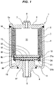
- Figs. 1 to 5 show an accumulator 1 according to a first embodiment of the present invention.
- the accumulator 1 according to the embodiment is a metal bellows type accumulator which employs a metal bellows as a bellows 9, and is structured as follows.
- an accumulator housing 2 is provided so as to have a port hole 5 which is connected to a pressure piping of a device (not shown), a bellows 9 and a bellows cap 10 are arranged in an inner portion of the housing 2, and an internal space of the housing 2 is partitioned into a gas chamber 11 in which a high-pressure gas (for example, a nitrogen gas) is charged, and a liquid chamber 12 which is communicated with the port hole 5.
- a high-pressure gas for example, a nitrogen gas
- the housing 2 is drawn as a housing constructed by a combination of a shell 3 which is formed into a closed-end cylindrical shape, an oil port 4 which is fixed (welded) to the center of a bottom portion of the shell 3 and is provided with the port hole 5 mentioned above, and a gas end cover 6 which is fixed (welded) to an upper end opening portion of the shell 3, however, a parts allocation structure of the housing 2 is not particularly limited.
- the shell 3 and the oil port 4 may be integrated, and the shell 3 and the gas end cover 6 may be integrated.
- a gas inlet port 7 for injecting the gas to the gas chamber 11 is provided in the gas end cover 6 or a corresponding part, and the gas inlet port 7 is closed by a gas plug 8 after injecting the gas.
- the bellows 9 is structured such that a fixed end 9a thereof is fixed (welded) to an inner surface of the gas end cover 6 which is an inner surface in an opposite port side of the housing 2, and a discoid bellows cap 10 is fixed (welded) to a floating end 9b thereof.
- the accumulator 1 is constructed as an internal gas type accumulator in which the gas chamber 11 is set in an inner peripheral side of the bellows 9 and the liquid chamber 12 is arranged in an outer peripheral side of the bellows 9.
- a vibration damping ring 13 is attached to an outer peripheral portion of the bellows cap 10 so as to prevent the bellows 9 and the bellows cap 10 from coming into contact with the inner surface of the housing 2, however, the vibration damping ring 13 does not achieve a sealing function.
- Reference numeral 14 denotes a protection ring.
- a seal holder 21 is fixed to a surface close to the port side in the bellows cap 10, and a discoid seal member 31 is retained by the seal holder 21.
- the seal holder 21 is obtained by integrally forming an annular flange portion 21b in an end portion close to the port side of a tubular portion 21a toward an inner side in a diametrical direction, and is fixed (by welding or fitting) to the bellows cap 10 by an end portion opposite to the port side of the tubular portion 21a.
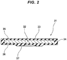
- the seal member 31 is obtained by attaching (vulcanization bonding) a rubber-like elastic body 33 to a surface of a discoid rigid plate 32 which is made of a metal or a hard resin, as shown by a single part drawing in Fig. 2 , an annular flexible portion 34, an opposite port side coating portion 35 and a port side coating portion 36 are integrally formed by the rubber-like elastic body 33, the annular flexible portion 34 being attached to an outer peripheral surface of the rigid plate 32, the opposite port side coating portion 35 being attached to an end surface opposite to the port in the rigid plate 32 and being formed into a thin film, and the port side coating portion 36 being attached to an end surface close to the port side in the rigid plate 32 and being formed into a thin film in the same manner, and an annular seal projection 37 is integrally formed so as to be positioned in the end surface close to the port side in the rigid plate 32.
- the seal projection 37 comes into contact with an inside end surface of the oil port 4 serving as the seal portion 15 of the accumulator 1 so as to be
- each of dimensional data is set as follows.
- an outer diameter of the rigid plate 32 is set to be smaller than an inner diameter of the seal holder 21, that is, an inner diameter of the flange portion 21b.
- an outer diameter of the flexible portion 34 that is, an outer diameter of the seal member 31 is set to be equal or approximately equal to an inner diameter of the tubular portion 21a in the seal holder and be somewhat smaller than the inner diameter, and is also set to be larger than the inner diameter of the seal holder 21, that is, the inner diameter of the flange portion 21b.
- a thickness of the flexible portion 34 is set to be equal or approximately equal to sum of a thickness of the rigid plate 32, a thickness of the opposite port side coating portion 35 and a thickness of the port side coating portion 36. Further, each of the sum of the thickness of the rigid plate 32, the thickness of the opposite port side coating portion 35 and the thickness of the port side coating portion 36 and the thickness of the flexible portion 34 is set to be equal to or approximately equal to a distance between the flange portion 21b and the bellows cap 10, however, since it is necessary to make the pressure of the liquid confined in the liquid chamber 12 at the zero-down time act on each of the port side end surface of the bellows cap 10 and the opposite port side end surface of the seal member 31, these thicknesses are preferably set to be somewhat smaller than the distance between the flange portion 21b and the bellows cap 10 for forming a small gap c1 ( Fig. 3 ) between the bellows cap 10 and the seal member 31.
- a communication path communicating the liquid chamber 12 and the gap c1 is provided for intruding the pressure of the liquid confined in the liquid chamber 12 at the zero-down time to the gap c1 between the bellows cap 10 and the seal member 31.
- the communication path may be constructed by the gap between the flexible portion 34 and the seal holder 21 (a communication path running into the gap c1 between the bellows cap 10 and the seal member 31 from the liquid chamber 12 via the gap between the flexible portion 34 and the flange portion 21b and the gap between the flexible portion 34 and the tubular portion 21a), however, the communication path is insufficient, the communication path may be formed by a notch which is provided partly on a circumference of the seal holder 21, a notch which is provided partly on a circumference of the flexible portion 34 or a through hole which is provided so as to pass through the seal member 31 in a thickness direction, each of which is not illustrated.
- the seal holder 21 retains only the seal member 31, and the seal holder 21 does not retain any kind of spring member (including a spring constructed by a rubber-like elastic body in addition to a spring made of a metal).
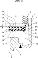
- Fig. 3 shows a state of the accumulator 1 at the steady activating time.
- the port hole 5 is connected to a pressure piping of a device (not shown).
- the seal member 31 is away from the seal portion 15 by moving together with the bellows cap 10 in a state in which the seal member 31 is retained by the seal holder 21. Accordingly, the port hole 5 is communicated with the liquid chamber 12. Therefore, since the liquid having a pressure at any given time is introduced to the liquid chamber 12 from the port hole 5 at pleasure, the bellows cap 10 moves at pleasure together with the seal member 31 in such a manner that the liquid pressure and the charged gas pressure are balanced with each other.
- the liquid within the liquid chamber 12 is discharged little by little from the port hole 5, and the bellows cap 10 is accordingly moved on the basis of the charged gas pressure in such a direction that the bellows cap 10 comes close to the seal portion 15, as shown in Fig 4 .
- the seal member 31 comes into contact with the seal portion 15 by the seal projection 37 so as to form the so-called zero-down state. Therefore, since the liquid chamber 12 is occluded and the partial liquid is confined in the liquid chamber 12, any further pressure reduction is not generated in the liquid chamber 12. Therefore, there is achieved a state in which the liquid pressure and the charged gas pressure are balanced in the inner and outer sides of the bellows 9.
- the liquid confined in the liquid chamber 12 may be called as a backup fluid (BF).
- the seal member 31 is obtained by attaching the flexible portion 34 constructed by the rubber-like elastic body to the outer peripheral surface of the rigid plate 32, and the flexible portion 34 allows the relative movement of the bellows cap 10 by shear deforming on the basis of the engagement with the seal holder 21, it is not necessary to set the allowance dimension for relatively moving the seal member 31 in the seal holder 21, and it is not necessary embed the spring member 41. Therefore, since the length of the seal holder 21 can be reduced in comparison with the prior art in Fig. 13 , it is possible to downsize the parts. Further, since the spring member 41 can be omitted, it is possible to reduce the parts number.
- the seal member 31 since the seal member 31 does not move while being in contact with the seal portion 15, but only the bellows cap 10 moves, it is possible to reduce the pressure difference generated when the liquid and the charged gas confined in the liquid chamber 12 at the zero-down time thermally expand.
- the seal projection 37 is attached to the rigid plate 32, it is possible to sufficiently secure the sealing performance even in the case that the seal portion 15 is constructed by the metal surface such as the end surface portion of the stay or the end surface portion of the oil port 4. Further, since the seal projection 37 and the flexible portion 34 are integrally formed, it is possible to facilitate the manufacturing process of the parts.
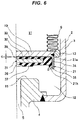
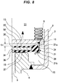
- an outer peripheral projection 38 is integrally formed in the port side end surface of the flexible portion 34 in the seal member 31, the outer peripheral projection 38 coming into contact with and engaging with the inside end surface of the flange portion 21b of the seal holder 21, as shown in Figs. 6 to 8 .
- the outer peripheral projection 38 is provided in an outermost peripheral portion of the port side end surface of the flexible portion 34.
- the outer peripheral projection 38 is provided circumferentially continuous (annular), however, may be provided circumferentially discontinuous.
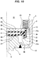
- a groove portion 39 is provided in each of the port side end surface and the opposite port side end surface of the flexible portion 34 in the seal member 31, the groove portion 39 being obtained by thinning the thickness of the flexible portion 34 partially in the diametrical direction, as shown in Figs. 9 to 11 .
- the groove portion 39 is provided in an inner peripheral side of the outer peripheral projection 38 in the port side end surface.
- the groove portion 39 is provided circumferentially continuous (annular), however, may be provided circumferentially discontinuous.
- the groove portion 39 may be provided only in any one of the port side end surface and the opposite port side end surface of the flexible portion 34.
- the accumulator 1 is constructed by the internal gas type accumulator in which the gas chamber 11 is set to the inner peripheral side of the bellows 9, and the liquid chamber 12 is arranged in the outer peripheral side of the bellows 9, however, the accumulator 1 may be constructed by an external gas type accumulator in which the gas chamber 11 is set to the outer peripheral side of the bellows 9 and the liquid chamber 12 is arranged in the inner peripheral side of the bellows 9 as shown in Fig. 13 mentioned above.
- the internal gas type accumulator and the external gas type accumulator are both included in the present invention.
- the seal portion 14 with which the seal member 31 comes into contact so as to be close to and away from is constructed by the inside end surface of the oil port 4, however, may be constructed by a lip seal which is formed by a rubber-like elastic body provided in a peripheral edge portion of an inside opening of the port hole as shown in Fig. 13 mentioned above.
- a stay member may be installed to an inner peripheral side of the bellows 9 in an inner side (close to the bellows cap side) of the oil port 4 for leveling up the height position of the seal portion 15, however, the seal portion 15 may be constructed by the end surface portion of the stay member in this case.
- the seal member 31 may be structured such that the rigid plate 32 comes into direct contact with the lip seal.
Description
- The present invention relates to an accumulator which is used as a pressure accumulator or a pulsation pressure damping device. The accumulator according to the present invention is used, for example, for a hydraulic piping in a vehicle such as a motor vehicle.
- There has been conventionally know an accumulator which is structured such that an internal space of an
accumulator housing 2 is partitioned into agas chamber 11 to which a high pressure gas is sealed and aliquid chamber 12 which is communicated with aport hole 5, by arranging abellows 9 and abellows cap 10 in an inner portion of theaccumulator housing 2 having theport hole 5 connected to a pressure piping of a device, as shown inFig. 12 . In the accumulator, in the case that the operation of the device stops and the pressure within the pressure piping is lowered, the liquid (the oil) within theliquid chamber 12 is discharged little by little from theport hole 5, thebellows 9 is accordingly elongated little by little due to the charged gas pressure, and thebellows cap 10 comes into contact with aseal portion 15 so as to form a so-called zero-down state. Theseal portion 15 is constructed by a lip seal which is provided in an inner opening peripheral edge portion of theport hole 5. Further, in this zero-down state, theliquid chamber 12 is occluded on the basis of the contact of thebellows cap 10 with theseal portion 15, the liquid is partially confined in theliquid chamber 12, and the pressure of the confined liquid is balanced with the gas pressure of thegas chamber 11. As a result, any excessive stress is not applied to thebellows 9, and it is accordingly possible to inhibit plastic deformation from being generated in the bellows 9 (refer toFig. 6 of patent document 1). - However, in the case that the zero-down state due to the operation stop of the device is generated under a low temperature condition, and the temperature rises thereafter, each of the liquid and the charged gas confined in the
liquid chamber 12 is thermally inflated, and the pressure rises. In this case, a rising degree of the pressure is greater in the liquid in comparison with the charged gas, however, since a pressure receiving area in thebellows cap 10 is set to be smaller than that in the charged gas side, thebellows cap 10 does not move until the liquid pressure becomes significantly greater than the gas pressure, and thebellows cap 10 does move away from theseal portion 15. Therefore, a pressure difference stretching for about several MPa may be generated between the liquid pressure and the gas pressure in inner and outer sides of thebellows 9, and there is a risk that the plastic deformation is generated in thebellows 9 if the great pressure difference is generated as mentioned above. - In order to dissolve the disadvantage mentioned above, the inventors of the present invention have proposed previously an accumulator which is provided with the following countermeasures.
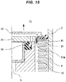
- More specifically, as shown in
Fig. 13 , in the accumulator, aseal member 31 is retained to theport hole 5 side of thebellows cap 10 via aseal holder 21, and theseal member 31 comes into contact with theseal portion 15 at the zero-down time. Theseal member 31 is constructed by a discoid rigid plate, and an outer diameter thereof is set to be larger than an inner diameter of aflange portion 21b of theseal holder 21. Therefore, theseal member 31 is retained by theseal holder 21. Further, since a thickness of theseal member 31 is set to be smaller than a distance between theflange portion 21b and thebellows cap 10, theseal member 31 can relatively move in relation to theseal holder 21 and thebellows cap 10 within a range of a dimensional difference. Further, since aspring member 41 pressing theseal member 31 is embedded between theflange portion 21b and theseal member 31, theseal member 31 is pressed to thebellows cap 10 in an initial state. - The accumulator is connected to a pressure piping of the device and is activated as follows.
- Since the
seal member 31 is away from theseal portion 15 by moving together with thebellows cap 10 in a state in which theseal member 31 is retained by theseal holder 21 at the steady activating time of the accumulator as shown inFig. 13 , theport hole 5 which is open to an inner peripheral side of theseal portion 15 is open. Therefore, theport hole 5 is communicated with theliquid chamber 12. Accordingly, since the liquid having a pressure at any given time is introduced to theliquid chamber 12 from theport hole 5, thebellows cap 10 moves at pleasure together with theseal member 31 in such a manner that the liquid pressure and the charged gas pressure are balanced with each other. - In the case that the operation of the device stops and the pressure within the pressure piping is lowered, the liquid within the
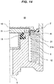
liquid chamber 12 is discharged little by little from theport hole 5, and thebellows cap 10 is accordingly moved on the basis of the charged gas pressure in such a direction that thebellows cap 10 comes close to theseal portion 15. As a result, theseal member 31 comes into contact with theseal portion 15 as shown inFig. 14 so as to form the zero-down state. Therefore, since theliquid chamber 12 is occluded and the partial liquid is confined in theliquid chamber 12, any further pressure reduction is not generated in the liquid chamber. Therefore, there is achieved a state in which the liquid pressure and the charged gas pressure are balanced in the inner and outer sides of thebellows 9. - In the case that the liquid and the charged gas confined in the
liquid chamber 12 are thermally expanded due to the rise of the atmosphere temperature in the zero-down state, that is, the state in which theseal member 31 comes into contact with theseal portion 15 and theliquid chamber 12 is occluded, the pressure difference is generated since the rising degree of the pressure is greater in the liquid than in the gas. However, in the accumulator, thebellows cap 10 moves toward a direction that thebellows cap 10 moves away from theseal portion 15 while compressing thespring member 41, on the basis of the pressure difference, as shown inFig. 15 . Accordingly, since the state in which the liquid pressure and the charged gas pressure are balanced is maintained, the pressure difference is not generated in the inner and outer sides of thebellows 9. As a result, it is possible to inhibit the plastic deformation from being generated in thebellows 9. At this time, since the pressure receiving area of theseal member 31 in the state in which theseal member 31 is in contact with theseal portion 15 is greater in the surface close to thebellows cap 10 side than the surface close to theseal portion 15 side, theseal member 31 does not move while being in contact with theseal portion 15 on the basis of the difference of the pressure receiving area in both the surfaces. Therefore, theport hole 5 open to the inner peripheral side of theseal portion 15 is kept closed. - As described above, according to the accumulator in
Fig. 13 , it is possible to reduce the pressure difference generated by the difference of coefficient of thermal expansion in the case that the liquid and the charged gas confined in theliquid chamber 12 thermally expands at the zero-down time. As a result, it is possible to inhibit the plastic deformation from being generated in the bellows 9 (refer toFigs. 1 to 3 of the patent document 1). - However, there has been room for improvement in the following points, in the accumulator shown in
Fig. 13 . - More specifically, since the accumulator shown in
Fig. 13 mentioned above reduces the pressure difference which is generated by the difference of coefficient of thermal expansion in the case that the liquid and the charged gas confined in theliquid chamber 12 thermally expands at the zero-down time, there occurs such an activation that theseal member 31 does not move while being in contact with theseal portion 15 and only thebellows cap 10 moves in the direction that thebellows cap 10 moves away from theseal portion 15. Therefore, theseal member 31 is structured such as to relatively move in relation to theseal holder 21 and thebellows cap 10, and an allowance dimension for relatively moving theseal member 31 is set in theseal holder 21 for enabling the relative movement. In other words, a distance between theflange portion 21b of theseal holder 21 and thebellows cap 10 is set to be greater than a thickness of theseal member 31, and thespring member 41 is embedded between theflange portion 21b and theseal member 31 under the condition. - Therefore, according to the accumulator in
Fig. 13 mentioned above, since it is necessary to embed thespring member 41 together with theseal member 31 within theseal holder 21 while setting a length of theseal holder 21 to be larger than the thickness of theseal member 31, the parts are large scaled and the number of the parts is large. On the contrary, the pressure difference reducing mechanism can be made further useful by making the parts compact and reducing the number of the parts. - Patent Document 1: Japanese Unexamined Patent Publication No.
2009-092145 - Non
pre-published EP 2 860 406 A1 relates to an accumulator which is used as a pressure accumulator or a pulsation pressure damping device comprising anaccumulator housing 2 which is provided with anoil port 3 connected to a pressure piping in one end and is provided with agas filling port 4 in the other end. Abellows 10 and abellows cap 11 are arranged in an inner portion of thehousing 2 sectioning an inner portion of thehousing 2 into agas chamber 12 and into afluid chamber 13 which is communicated with theoil port 3. The housing is constructed by a closed-andcylindrical shell 5, and an end cover 6 which is fixed to one end opening portion of the shell. The end cover 6 is provided with thegas filling port 4 which is closed by agas plug 7 after being filled with the gas. Thebellows 10 is structured such that a fixed end 10a is fixed to the end cover 6, and adiscoid bellows cap 11 is fixed to a floating end 10b. Adamping ring 14 is attached to an outer peripheral portion of thebellows cap 11 so as to prevent thebellows 10 and thebellows cap 11 from coming into contact with the inner surface of thehousing 2. Further, a pressure decreasingtime safety mechanism 21 is structured such that a seal 23 seats on aseat surface 8 in the inner portion of the housing in the case that the pressure of thefluid chamber 13 is decreased together with the pressure decrease of the pressure piping, thereby sealing thefluid chamber 13 and trapping the partial liquid in thefluid chamber 13. - The present invention is made by taking the above points into consideration, and an object of the present invention is to provide an accumulator which can reduce a pressure difference generated by a difference of coefficient of thermal expansion in the case that the liquid and the charged gas confined in the liquid chamber thermally expands at the zero-down time, can accordingly inhibit the plastic deformation from being generated in the bellows, and is structured such that parts are compact and the number of the parts is small.
- In order to achieve the object mentioned above, according to a first aspect of the present invention, there is provided an accumulator according to claim 1.
- Further, an accumulator according to a second aspect of the present invention is the accumulator described in the first aspect mentioned above, wherein a circumferentially continuous or discontinuous outer peripheral projection is provided in one surface in a thickness direction of the flexible portion, the outer peripheral projection coming into contact with the flange portion provided in the seal holder.
- Further, an accumulator according to a third aspect of the present invention is the accumulator described in the first or second aspect mentioned above, wherein a groove portion is provided in both surfaces or one surface in a thickness direction of the flexible portion, the groove portion thinning the flexible portion at a part in a diametrical direction.
- Further, an accumulator according to a fourth aspect of the present invention is the accumulator described in the first, second or third aspect mentioned above, wherein a seal projection is provided in one surface in a thickness direction of the rigid plate, the seal projection being constructed by a rubber-like elastic body coming into contact with the seal portion, and the seal projection is formed integrally with the flexible portion.
- In the accumulator according to the present invention having the structure mentioned above, the seal member is obtained by attaching the flexible portion constructed by the rubber-like elastic body to the outer peripheral surface of the rigid plate, and the flexible portion allows the relative movement of the bellows cap by the shear deformation on the basis of the engagement with the seal holder. Therefore, the seal holder and the bellows cap relatively move in relation to the seal member by the shear deformation of the seal member. As a result, it is not necessary to set the allowance dimension for the relative movement in the seal holder as is different from the prior art shown in
Fig. 13 mentioned above, and it is not necessary to embed the spring member in the seal holder. Accordingly, it is possible to downsize the parts by shortening the length of the seal holder in relation to the prior art shown inFig. 13 mentioned above, and it is possible to reduce the parts number by omitting the spring member. - Further, the accumulator according to the present invention having the structure mentioned above is connected to the pressure piping of the device, and is activated as follows.
- Since the seal member is away from the seal portion by moving together with the bellows cap in a state in which the seal member is retained by the seal holder at the steady activating time of the accumulator, the port hole is communicated with the liquid chamber. Therefore, since the liquid having a pressure at any given time is introduced to the liquid chamber from the port hole at pleasure, the bellows cap moves at pleasure together with the seal member in such a manner that the liquid pressure and the charged gas pressure are balanced with each other.
- In the case that the operation of the device stops and the pressure within the pressure piping is lowered, the liquid within the liquid chamber is discharged little by little from the port hole, and the bellows cap is accordingly moved on the basis of the charged gas pressure in such a direction that the bellows cap comes close to the seal portion. As a result, the seal member comes into contact with the seal portion so as to form the so-called zero-down state. Therefore, since the liquid chamber is occluded and the partial liquid is confined in the liquid chamber, any further pressure reduction is not generated in the liquid chamber. Therefore, there is achieved a state in which the liquid pressure and the charged gas pressure are balanced in the inner and outer sides of the bellows.
- In the case that the liquid and the charged gas confined in the liquid chamber are thermally expanded due to the rise of the atmosphere temperature in the zero-down state, that is, the state in which the seal member comes into contact with the seal portion and the liquid chamber is occluded, the pressure difference is generated since the rising degree of the pressure is greater in the liquid than in the gas. However, in the accumulator, the bellows cap moves toward a direction that the bellows cap moves away from the seal portion on the basis of the pressure difference. Accordingly, since the state in which the liquid pressure and the charged gas pressure are balanced is maintained, the pressure difference is not generated in the inner and outer sides of the bellows. As a result, it is possible to inhibit the plastic deformation from being generated in the bellows. At this time, since the pressure receiving area of the seal member in the state in which the seal member is in contact with the seal portion is greater in the surface close to the bellows cap side than the surface close to the seal portion side, the seal member does not move while being in contact with the seal portion on the basis of the difference of the pressure receiving area in both the surfaces. Therefore, the port hole is kept closed. Further, since the seal member is structured such that the flexible portion constructed by the rubber-like elastic body is attached to the outer peripheral surface of the rigid plate as mentioned above, the flexible portion shear deforms on the basis of the engagement with the seal holder so as to allow the relative movement of the bellows cap. In other words, the seal holder and the bellows cap move toward the direction that the seal holder and the bellows cap move away from the seal portion while shear deforming the flexible portion.
- The seal member is preferably structured such that the outer diameter of the rigid plate is set to be smaller than the inner diameter of the flange portion provided in the seal holder, and the outer diameter of the flexible portion is set to be larger than the inner diameter of the flange portion. According to this structure, the flexible portion is easily shear deformed on the basis of the engagement with the seal holder.
- Further, in order to easily shear deform the flexible portion, it is preferable that the circumferentially continuous or discontinuous outer peripheral projection is provided in one surface in the thickness direction of the flexible portion, the outer peripheral projection coming into contact with the flange portion provided in the seal holder, or the groove portion is provided in both the surfaces or one surface in the thickness direction of the flexible portion, the groove portion partly thinning the flexible portion in the diametrical direction. According to these structures, it is possible to increase an amount of shear deformation of the flexible portion, and t is possible to increase the amount of relative movement between the seal member, and the seal holder and the bellows cap.
- Further, the seal member may be structured such that the seal projection constructed by the rubber-like elastic body coming into contact with the seal portion is provided in one surface in the thickness direction of the rigid plate. According to this structure, it is possible to sufficiently secure a sealing performance in relation to the liquid, even in the case that the seal portion is constructed by a metal surface such as an end surface portion of a stay or an end surface portion of an oil port. Further, in this case, an elastic body forming frequency can be reduced at the parts manufacturing time by integrally forming the seal projection and the flexible portion.
- As described above, according to the present invention, the seal member is obtained by attaching the flexible portion constructed by the rubber-like elastic body to the outer peripheral surface of the rigid plate, and the flexible portion allows the relative movement of the bellows cap by the shear deformation on the basis of the engagement with the seal holder. Therefore, it is not necessary to set the allowance dimension for relatively moving the seal member in the seal holder, and it is not necessary to embed the spring member in the seal holder. Accordingly, it is possible to downsize the parts by shortening the length of the seal holder, and it is possible to reduce the parts number by omitting the spring member. Further, according to the present invention, since the seal member does not move while keeping the contact with the seal portion and only the bellows cap moves, it is additionally possible to reduce the pressure difference which is generated in the case that the liquid and the charged gas confined in the liquid chamber thermally expand at the zero-down time. Therefore, according to an initial object of the present invention, it is possible to inhibit the plastic deformation from being generated in the bellows when the liquid and the charged gas confined in the liquid chamber thermally expand at the zero-down time, and it is further possible to provide the accumulator structured such that the parts are downsized and the parts number is reduced.
- Further, the flexible portion tends to shear deform in the case that the flexible portion engages with the seal holder, by setting the outer diameter of the flexible portion larger than the inner diameter of the flange portion as well as setting the outer diameter of the rigid plate smaller than the inner diameter of the flange portion provided in the seal holder, and it is possible to increase the amount of the relative movement between the seal member, and the seal holder and the bellow cap by the provision of the outer peripheral projection or the groove in the flexible portion. As a result, even in the case that the pressure difference generated in the case that the liquid and the charged gas confined in the liquid chamber thermally expand is great at the zero-down time, it is possible to quickly reduce the pressure difference.
- Further, it is possible to sufficiently secure the sealing performance by the provision of the seal projection in the rigid plate even in the case that the seal portion is constructed by the metal surface such as the end surface portion of the stay or the end surface portion of the oil port, and it is possible to facilitate the manufacturing process of the parts by integrally forming the seal projection and the flexible portion.
-
-
Fig. 1 is a cross sectional view of an accumulator according to a first embodiment of the present invention; -
Fig. 2 is an enlarged cross sectional view of a seal member which is provided in the accumulator; -
Fig. 3 is an enlarged cross sectional view of a substantial part and shows a state of the accumulator at the steady activating time; -
Fig. 4 is an enlarged cross sectional view of a substantial part and shows a state of the accumulator at the zero-down time; -
Fig. 5 is an enlarged cross sectional view of a substantial part and shows a state of the accumulator at the thermal expanding time in a zero-down state; -
Fig. 6 is a cross sectional view of a substantial part and shows a state of an accumulator according to a second embodiment of the present invention at the steady activating time; -
Fig. 7 is a cross sectional view of a substantial part and shows a state of the accumulator at the zero-down time; -
Fig. 8 is a cross sectional view of a substantial part and shows a state of the accumulator at the thermal expanding time in a zero-down state; -
Fig. 9 is a cross sectional view of a substantial part and shows a state of an accumulator according to a third embodiment of the present invention at the steady activating time; -
Fig. 10 is a cross sectional view of a substantial part and shows a state of the accumulator at the zero-down time; -
Fig. 11 is a cross sectional view of a substantial part and shows a state of the accumulator at the thermal expanding time in a zero-down state; -
Fig. 12 is a cross sectional view of an accumulator according to a prior art; -
Fig. 13 is a cross sectional view of a substantial part and shows a state of an accumulator according to the other prior art at the steady activating time; -
Fig. 14 is a cross sectional view of a substantial part and shows a state of the accumulator at the zero-down time; and -
Fig. 15 is a cross sectional view of a substantial part and shows a state of the accumulator at the thermal expanding time in a zero-down state. - The following embodiments are included in the present invention.
- (1) A seal member is provided in a bellows cap side for sealing the liquid (the backup fluid (BF)) which is confined in the liquid chamber, at the zero-down time.
- (2) A gasket seal having a rubber portion (an elastic body portion) in an outer peripheral portion of a metal plate is used as the seal member.
- (3) The gasket seal is provided between the bellows cap and the seal holder, and the rubber portion in the outer peripheral portion of the seal is deformed by the seal holder at the temperature rising time in the zero-down state. On the basis of the deformation, the seal holder and the bellows cap bonded by the seal holder displace in a direction of contracting the bellows, and enlarge a volumetric capacity of the BF.
- (4) A seal projection may be provided in one surface of the metal plate.
- (5) A rubber (an elastic body) projection or/and a groove portion may be provided in the rubber portion in the outer peripheral portion of the seal.
- Next, a description will be given of embodiments according to the present invention with reference to the accompanying drawings.
-
Figs. 1 to 5 show an accumulator 1 according to a first embodiment of the present invention. The accumulator 1 according to the embodiment is a metal bellows type accumulator which employs a metal bellows as abellows 9, and is structured as follows. - More specifically, as shown in
Fig. 1 , anaccumulator housing 2 is provided so as to have aport hole 5 which is connected to a pressure piping of a device (not shown), abellows 9 and abellows cap 10 are arranged in an inner portion of thehousing 2, and an internal space of thehousing 2 is partitioned into agas chamber 11 in which a high-pressure gas (for example, a nitrogen gas) is charged, and aliquid chamber 12 which is communicated with theport hole 5. Thehousing 2 is drawn as a housing constructed by a combination of ashell 3 which is formed into a closed-end cylindrical shape, anoil port 4 which is fixed (welded) to the center of a bottom portion of theshell 3 and is provided with theport hole 5 mentioned above, and a gas end cover 6 which is fixed (welded) to an upper end opening portion of theshell 3, however, a parts allocation structure of thehousing 2 is not particularly limited. For example, theshell 3 and theoil port 4 may be integrated, and theshell 3 and the gas end cover 6 may be integrated. In any event, agas inlet port 7 for injecting the gas to thegas chamber 11 is provided in the gas end cover 6 or a corresponding part, and thegas inlet port 7 is closed by agas plug 8 after injecting the gas. - The
bellows 9 is structured such that afixed end 9a thereof is fixed (welded) to an inner surface of the gas end cover 6 which is an inner surface in an opposite port side of thehousing 2, and a discoid bellowscap 10 is fixed (welded) to a floatingend 9b thereof. As a result, the accumulator 1 is constructed as an internal gas type accumulator in which thegas chamber 11 is set in an inner peripheral side of thebellows 9 and theliquid chamber 12 is arranged in an outer peripheral side of thebellows 9. Avibration damping ring 13 is attached to an outer peripheral portion of the bellows cap 10 so as to prevent thebellows 9 and the bellows cap 10 from coming into contact with the inner surface of thehousing 2, however, thevibration damping ring 13 does not achieve a sealing function.Reference numeral 14 denotes a protection ring. - A
seal holder 21 is fixed to a surface close to the port side in the bellows cap 10, and adiscoid seal member 31 is retained by theseal holder 21. - The
seal holder 21 is obtained by integrally forming anannular flange portion 21b in an end portion close to the port side of atubular portion 21a toward an inner side in a diametrical direction, and is fixed (by welding or fitting) to the bellows cap 10 by an end portion opposite to the port side of thetubular portion 21a. - The
seal member 31 is obtained by attaching (vulcanization bonding) a rubber-likeelastic body 33 to a surface of a discoidrigid plate 32 which is made of a metal or a hard resin, as shown by a single part drawing inFig. 2 , an annularflexible portion 34, an opposite portside coating portion 35 and a portside coating portion 36 are integrally formed by the rubber-likeelastic body 33, the annularflexible portion 34 being attached to an outer peripheral surface of therigid plate 32, the opposite portside coating portion 35 being attached to an end surface opposite to the port in therigid plate 32 and being formed into a thin film, and the portside coating portion 36 being attached to an end surface close to the port side in therigid plate 32 and being formed into a thin film in the same manner, and anannular seal projection 37 is integrally formed so as to be positioned in the end surface close to the port side in therigid plate 32. Theseal projection 37 comes into contact with an inside end surface of theoil port 4 serving as theseal portion 15 of the accumulator 1 so as to be close to and away from the inside end surface. Therigid plate 32 is coated its whole surface by the rubber-likeelastic body 33. - In the
seal holder 21 and theseal member 31, each of dimensional data is set as follows. - More specifically, first of all, in the dimensions in the diametrical direction, an outer diameter of the
rigid plate 32 is set to be smaller than an inner diameter of theseal holder 21, that is, an inner diameter of theflange portion 21b. On the contrary, an outer diameter of theflexible portion 34, that is, an outer diameter of theseal member 31 is set to be equal or approximately equal to an inner diameter of thetubular portion 21a in the seal holder and be somewhat smaller than the inner diameter, and is also set to be larger than the inner diameter of theseal holder 21, that is, the inner diameter of theflange portion 21b. - Further, in the dimensions in a thickness direction, a thickness of the
flexible portion 34 is set to be equal or approximately equal to sum of a thickness of therigid plate 32, a thickness of the opposite portside coating portion 35 and a thickness of the portside coating portion 36. Further, each of the sum of the thickness of therigid plate 32, the thickness of the opposite portside coating portion 35 and the thickness of the portside coating portion 36 and the thickness of theflexible portion 34 is set to be equal to or approximately equal to a distance between theflange portion 21b and the bellows cap 10, however, since it is necessary to make the pressure of the liquid confined in theliquid chamber 12 at the zero-down time act on each of the port side end surface of the bellows cap 10 and the opposite port side end surface of theseal member 31, these thicknesses are preferably set to be somewhat smaller than the distance between theflange portion 21b and the bellows cap 10 for forming a small gap c1 (Fig. 3 ) between the bellows cap 10 and theseal member 31. - Further, in conjunction with this, a communication path communicating the
liquid chamber 12 and the gap c1 is provided for intruding the pressure of the liquid confined in theliquid chamber 12 at the zero-down time to the gap c1 between the bellows cap 10 and theseal member 31. The communication path may be constructed by the gap between theflexible portion 34 and the seal holder 21 (a communication path running into the gap c1 between the bellows cap 10 and theseal member 31 from theliquid chamber 12 via the gap between theflexible portion 34 and theflange portion 21b and the gap between theflexible portion 34 and thetubular portion 21a), however, the communication path is insufficient, the communication path may be formed by a notch which is provided partly on a circumference of theseal holder 21, a notch which is provided partly on a circumference of theflexible portion 34 or a through hole which is provided so as to pass through theseal member 31 in a thickness direction, each of which is not illustrated. - The
seal holder 21 retains only theseal member 31, and theseal holder 21 does not retain any kind of spring member (including a spring constructed by a rubber-like elastic body in addition to a spring made of a metal). - Next, a description will be given of an activation of the accumulator 1 having the structure mentioned above.
-
Fig. 3 shows a state of the accumulator 1 at the steady activating time. Theport hole 5 is connected to a pressure piping of a device (not shown). At this steady activating time, theseal member 31 is away from theseal portion 15 by moving together with the bellows cap 10 in a state in which theseal member 31 is retained by theseal holder 21. Accordingly, theport hole 5 is communicated with theliquid chamber 12. Therefore, since the liquid having a pressure at any given time is introduced to theliquid chamber 12 from theport hole 5 at pleasure, the bellows cap 10 moves at pleasure together with theseal member 31 in such a manner that the liquid pressure and the charged gas pressure are balanced with each other. - In the case that the operation of the device stops and the pressure within the pressure piping is lowered from the state in
Fig. 3 , the liquid within theliquid chamber 12 is discharged little by little from theport hole 5, and the bellows cap 10 is accordingly moved on the basis of the charged gas pressure in such a direction that the bellows cap 10 comes close to theseal portion 15, as shown inFig 4 . As a result, theseal member 31 comes into contact with theseal portion 15 by theseal projection 37 so as to form the so-called zero-down state. Therefore, since theliquid chamber 12 is occluded and the partial liquid is confined in theliquid chamber 12, any further pressure reduction is not generated in theliquid chamber 12. Therefore, there is achieved a state in which the liquid pressure and the charged gas pressure are balanced in the inner and outer sides of thebellows 9. The liquid confined in theliquid chamber 12 may be called as a backup fluid (BF). - In the case that the liquid and the charged gas confined in the
liquid chamber 12 are thermally expanded due to the rise of the atmosphere temperature in the zero-down state inFig. 4 , that is, the state in which theseal member 31 comes into contact with theseal portion 15 and theliquid chamber 12 is occluded, the pressure difference is generated since the rising degree of the pressure is greater in the liquid than in the gas. However, in the accumulator 1, the bellows cap 10 moves toward a direction that the bellows cap 10 moves away from theseal portion 15 on the basis of the pressure difference while shear deforming theflexible portion 34. Accordingly, since the state in which the liquid pressure and the charged gas pressure are balanced is maintained, the pressure difference is not generated in the inner and outer sides of thebellows 9. As a result, it is possible to inhibit the plastic deformation from being generated in thebellows 9. At this time, since the pressure receiving area of theseal member 31 in the state in which theseal member 31 is in contact with theseal portion 15 is greater in the surface close to the bellows cap 10 side than the surface close to theseal portion 15 side (this is because the portion closer to the inner peripheral side than theseal projection 37 does not act as the pressure receiving surface on the surface close to theseal portion 15 side), theseal member 31 does not move while being in contact with theseal portion 15 on the basis of the difference of the pressure receiving area in both the surfaces. Therefore, theport hole 5 is kept closed, and the gap between the bellows cap 10 and theseal member 31 is enlarged its magnitude (c1 < c2). - In the case that the operation of the device is restarted and the pressure within the pressure piping rises from the state in
Fig. 4 orFig. 5 , the pressure acts on theseal member 31 from theport hole 5 so as to move theseal member 31 away from theseal portion 15. Therefore, theport hole 5 is opened, the liquid is introduced to theliquid chamber 12, and the state returns to the state at the steady activating time inFig. 3 . - According to the accumulator 1 having the structure mentioned above, since the
seal member 31 is obtained by attaching theflexible portion 34 constructed by the rubber-like elastic body to the outer peripheral surface of therigid plate 32, and theflexible portion 34 allows the relative movement of the bellows cap 10 by shear deforming on the basis of the engagement with theseal holder 21, it is not necessary to set the allowance dimension for relatively moving theseal member 31 in theseal holder 21, and it is not necessary embed thespring member 41. Therefore, since the length of theseal holder 21 can be reduced in comparison with the prior art inFig. 13 , it is possible to downsize the parts. Further, since thespring member 41 can be omitted, it is possible to reduce the parts number. - Further, according to the accumulator 1 having the structure mentioned above, since the
seal member 31 does not move while being in contact with theseal portion 15, but only the bellows cap 10 moves, it is possible to reduce the pressure difference generated when the liquid and the charged gas confined in theliquid chamber 12 at the zero-down time thermally expand. - Therefore, according to the above, it is possible to inhibit the plastic deformation from being generated in the bellows as originally intended when the liquid and the charged gas confined in the
liquid chamber 12 at the zero-down time thermally expand. Further, it is possible to provide the accumulator structured such that the parts are downsized and the parts number is reduced. Further, since theseal projection 37 is attached to therigid plate 32, it is possible to sufficiently secure the sealing performance even in the case that theseal portion 15 is constructed by the metal surface such as the end surface portion of the stay or the end surface portion of theoil port 4. Further, since theseal projection 37 and theflexible portion 34 are integrally formed, it is possible to facilitate the manufacturing process of the parts. - In the accumulator 1 according to the first embodiment mentioned above, there can be thought that the structures are added and changed as follows.
- As a second embodiment, an outer
peripheral projection 38 is integrally formed in the port side end surface of theflexible portion 34 in theseal member 31, the outerperipheral projection 38 coming into contact with and engaging with the inside end surface of theflange portion 21b of theseal holder 21, as shown inFigs. 6 to 8 . According to the structure, it is possible to increase a deforming amount of the shear deformation of theflexible portion 34, and it is possible to increase the amount of the relative movement between theseal member 31 and theseal holder 21, further between theseal member 31 and the bellows cap 10. The outerperipheral projection 38 is provided in an outermost peripheral portion of the port side end surface of theflexible portion 34. The outerperipheral projection 38 is provided circumferentially continuous (annular), however, may be provided circumferentially discontinuous. - As a third embodiment, a
groove portion 39 is provided in each of the port side end surface and the opposite port side end surface of theflexible portion 34 in theseal member 31, thegroove portion 39 being obtained by thinning the thickness of theflexible portion 34 partially in the diametrical direction, as shown inFigs. 9 to 11 . According to the structure, in the same manner as the second embodiment mentioned above, it is possible to increase the deforming amount of the shear deformation of theflexible portion 34, and it is possible to increase the amount of the relative movement between theseal member 31 and theseal holder 21, further between theseal member 31 and the bellows cap 10. Since the outerperipheral projection 38 according to the second embodiment is provided in the port side end surface of theflexible portion 34 in the drawing, thegroove portion 39 is provided in an inner peripheral side of the outerperipheral projection 38 in the port side end surface. Thegroove portion 39 is provided circumferentially continuous (annular), however, may be provided circumferentially discontinuous. Thegroove portion 39 may be provided only in any one of the port side end surface and the opposite port side end surface of theflexible portion 34. - In the first embodiment, the accumulator 1 is constructed by the internal gas type accumulator in which the
gas chamber 11 is set to the inner peripheral side of thebellows 9, and theliquid chamber 12 is arranged in the outer peripheral side of thebellows 9, however, the accumulator 1 may be constructed by an external gas type accumulator in which thegas chamber 11 is set to the outer peripheral side of thebellows 9 and theliquid chamber 12 is arranged in the inner peripheral side of thebellows 9 as shown inFig. 13 mentioned above. In other words, the internal gas type accumulator and the external gas type accumulator are both included in the present invention. - In the first embodiment mentioned above, the
seal portion 14 with which theseal member 31 comes into contact so as to be close to and away from is constructed by the inside end surface of theoil port 4, however, may be constructed by a lip seal which is formed by a rubber-like elastic body provided in a peripheral edge portion of an inside opening of the port hole as shown inFig. 13 mentioned above. Further, in the external gas type accumulator, a stay member may be installed to an inner peripheral side of thebellows 9 in an inner side (close to the bellows cap side) of theoil port 4 for leveling up the height position of theseal portion 15, however, theseal portion 15 may be constructed by the end surface portion of the stay member in this case. Further, in the case that theseal portion 15 is constructed by the lip seal, theseal member 31 may be structured such that therigid plate 32 comes into direct contact with the lip seal. -
- 1 accumulator
- 2 housing
- 3 shell
- 4 oil port
- 5 port hole
- 6 gas end cover
- 7 gas inlet port
- 8 gas plug
- 9 bellows
- 9a fixed end
- 9b floating end
- 10 bellows cap
- 11 gas chamber
- 12 liquid chamber
- 13 vibration damping ring
- 14 protection ring
- 15 seal portion
- 21 seal holder
- 21a tubular portion
- 21b flange portion
- 31 seal member
- 32 rigid plate
- 33 rubber-like elastic body
- 34 flexible portion
- 35, 36 coating portion
- 37 seal projection
- 38 outer peripheral projection
- 39 groove portion
Claims (4)
- An accumulator comprising:an accumulator housing (2) which has a port hole (5) connectable to a pressure piping of a device;a bellows (9) and a bellows cap (10) which is arranged in an inner portion of said housing so as to partition an internal space of said housing into a gas chamber (11) to which a high-pressure gas is charged and a liquid chamber (12) which is communicated with said port hole; anda seal member (31) which is retained to the port hole side of said bellows cap via a seal holder (21),wherein said seal member (31) moves together with said bellows cap (10) at a steady activating time, said seal member comes into contact with a seal portion (15) which is provided in an inner portion of said housing so as to occlude said liquid chamber (12) in the case that an operation of said device stops and the pressure within said pressure piping is lowered, whereinsaid seal member (31) is obtained by attaching a flexible portion (34) constructed by a rubber-like elastic body to an outer peripheral surface of a rigid plate (32), such that said rigid plate (32) is set so that an outer diameter is smaller than an inner diameter of a flange portion (21b) provided in said seal holder (21), andsaid flexible portion (34) is set so that an outer diameter is larger than the inner diameter of said flange portion, wherein said flexible portion allows relative movement of said bellows cap by shear deformation on the basis of engagement with said seal holder, whensaid bellows cap (10) moves away from said seal portion (15) while the seal member (31) is in contact with said seal portion (15) in the case that the liquid confined in said liquid chamber thermally expands in a state in which said liquid chamber is occluded.
- The accumulator according to claim 1, wherein a circumferentially continuous or discontinuous outer peripheral projection (38) is provided in one surface in a thickness direction of said flexible portion (34), the outer peripheral projection coming into contact with the flange portion (21) provided in said seal holder.
- The accumulator according to claim 1 or 2, wherein a groove portion (39) is provided in both surfaces or one surface in a thickness direction of said flexible portion, the groove portion thinning said flexible portion at a part in a diametrical direction.
- The accumulator according to claim 1, 2 or 3, wherein a seal projection (37) is provided in one surface in a thickness direction of said rigid plate (32), the seal projection being constructed by a rubber-like elastic body coming into contact with said seal portion (15), and said seal projection is formed integrally with said flexible portion (34).
Applications Claiming Priority (2)
| Application Number | Priority Date | Filing Date | Title |
|---|---|---|---|
| JP2013027631 | 2013-02-15 | ||
| PCT/JP2013/082656 WO2014125703A1 (en) | 2013-02-15 | 2013-12-05 | Accumulator |
Publications (3)
| Publication Number | Publication Date |
|---|---|
| EP2957776A1 EP2957776A1 (en) | 2015-12-23 |
| EP2957776A4 EP2957776A4 (en) | 2016-02-24 |
| EP2957776B1 true EP2957776B1 (en) | 2018-09-19 |
Family
ID=51353722
Family Applications (1)
| Application Number | Title | Priority Date | Filing Date |
|---|---|---|---|
| EP13875034.4A Active EP2957776B1 (en) | 2013-02-15 | 2013-12-05 | Accumulator |
Country Status (5)
| Country | Link |
|---|---|
| US (1) | US9328746B2 (en) |
| EP (1) | EP2957776B1 (en) |
| JP (1) | JP6165833B2 (en) |
| CN (1) | CN104583606B (en) |
| WO (1) | WO2014125703A1 (en) |
Families Citing this family (15)
| Publication number | Priority date | Publication date | Assignee | Title |
|---|---|---|---|---|
| EP3118463B1 (en) * | 2014-03-11 | 2020-04-29 | Eagle Industry Co., Ltd. | Accumulator |
| JP6754762B2 (en) | 2015-06-22 | 2020-09-16 | イーグル工業株式会社 | accumulator |
| EP3404271B1 (en) * | 2016-01-13 | 2021-01-27 | Eagle Industry Co., Ltd. | Accumulator |
| US10907657B2 (en) | 2016-12-02 | 2021-02-02 | Eagle Industry Co., Ltd. | Accumulator |
| CN106523569B (en) * | 2017-01-12 | 2019-06-25 | 常州万安汽车部件科技有限公司 | Oil gas shock mitigation system |
| WO2018143065A1 (en) | 2017-02-03 | 2018-08-09 | イーグル工業株式会社 | Accumulator |
| US10914323B2 (en) | 2017-02-03 | 2021-02-09 | Eagle Industry Co., Ltd. | Accumulator |
| CN106764222B (en) * | 2017-02-03 | 2018-09-14 | 北京华德创业环保设备有限公司 | Shell and tube fluid flow straightener |
| WO2018143030A1 (en) | 2017-02-03 | 2018-08-09 | イーグル工業株式会社 | Accumulator |
| DE102018007279A1 (en) * | 2018-09-14 | 2020-03-19 | Hydac Technology Gmbh | Bellows accumulator |
| CN109505809A (en) * | 2018-12-28 | 2019-03-22 | 中国航空工业集团公司西安飞行自动控制研究所 | A kind of pressure hull structure of bellows accumulator |
| CN111140557A (en) * | 2019-12-19 | 2020-05-12 | 安徽威迈光机电科技有限公司 | S-shaped bellows type energy accumulator with novel structure |
| JP7373453B2 (en) | 2020-04-10 | 2023-11-02 | 株式会社Ihiエアロスペース | Liquid propellant supply system and satellite propulsion system |
| CN112879485B (en) * | 2020-04-27 | 2022-11-25 | 北京京西重工有限公司 | Air suspension assembly and bellows for an air suspension assembly |
| CN112535913B (en) * | 2020-11-19 | 2022-06-03 | 无锡市添彩环保科技有限公司 | Explosion-proof dust remover with explosion-proof function and explosion-proof control method thereof |
Family Cites Families (11)
| Publication number | Priority date | Publication date | Assignee | Title |
|---|---|---|---|---|
| JPH1026173A (en) * | 1996-07-08 | 1998-01-27 | Nobuyuki Kobayashi | Damper for vibration damping |
| JP4718129B2 (en) * | 2003-07-30 | 2011-07-06 | 日本発條株式会社 | Brake system parts for vehicles |
| JP5102576B2 (en) | 2007-10-10 | 2012-12-19 | Nok株式会社 | accumulator |
| JP5016453B2 (en) * | 2007-11-20 | 2012-09-05 | Nok株式会社 | accumulator |
| JP5201722B2 (en) * | 2008-03-26 | 2013-06-05 | イーグル工業株式会社 | Metal bellows type accumulator |
| JP5474333B2 (en) * | 2008-11-05 | 2014-04-16 | イーグル工業株式会社 | accumulator |
| JP5108733B2 (en) | 2008-11-27 | 2012-12-26 | Nok株式会社 | accumulator |
| JP2010151286A (en) * | 2008-12-26 | 2010-07-08 | Nok Corp | Metallic bellows type accumulator |
| JP5374435B2 (en) * | 2010-04-20 | 2013-12-25 | イーグル工業株式会社 | accumulator |
| JP5872342B2 (en) | 2012-03-22 | 2016-03-01 | イーグル工業株式会社 | accumulator |
| US9188139B2 (en) * | 2012-06-11 | 2015-11-17 | Eagle Industry Co., Ltd. | Accumulator |
-
2013
- 2013-12-05 CN CN201380042811.1A patent/CN104583606B/en active Active
- 2013-12-05 EP EP13875034.4A patent/EP2957776B1/en active Active
- 2013-12-05 JP JP2015500099A patent/JP6165833B2/en active Active
- 2013-12-05 US US14/421,167 patent/US9328746B2/en active Active
- 2013-12-05 WO PCT/JP2013/082656 patent/WO2014125703A1/en active Application Filing
Non-Patent Citations (1)
| Title |
|---|
| None * |
Also Published As
| Publication number | Publication date |
|---|---|
| WO2014125703A1 (en) | 2014-08-21 |
| US9328746B2 (en) | 2016-05-03 |
| EP2957776A4 (en) | 2016-02-24 |
| CN104583606A (en) | 2015-04-29 |
| EP2957776A1 (en) | 2015-12-23 |
| JP6165833B2 (en) | 2017-07-19 |
| CN104583606B (en) | 2017-03-29 |
| US20150204357A1 (en) | 2015-07-23 |
| JPWO2014125703A1 (en) | 2017-02-02 |
Similar Documents
| Publication | Publication Date | Title |
|---|---|---|
| EP2957776B1 (en) | Accumulator | |
| US7770599B2 (en) | Accumulator | |
| US8096324B2 (en) | Accumulator | |
| US8371336B2 (en) | Accumulator | |
| US9027600B2 (en) | Accumulator | |
| US9188139B2 (en) | Accumulator | |
| CN107532615B (en) | Accumulator | |
| US7810522B1 (en) | Accumulator | |
| EP3306109B1 (en) | Metal bellows-type accumulator | |
| EP3306108B1 (en) | Metal bellows-type accumulator | |
| JP5374435B2 (en) | accumulator | |
| US10077787B2 (en) | Accumulator | |
| JP6979071B2 (en) | accumulator | |
| US9689405B1 (en) | Hydraulic accumulator | |
| US9512835B2 (en) | High pressure bellows assembly | |
| EP3252318B1 (en) | Hydraulic accumulator | |
| JP6470995B2 (en) | accumulator | |
| JPH11230102A (en) | Accumulator |
Legal Events
| Date | Code | Title | Description |
|---|---|---|---|
| PUAI | Public reference made under article 153(3) epc to a published international application that has entered the european phase |
Free format text: ORIGINAL CODE: 0009012 |
|
| 17P | Request for examination filed |
Effective date: 20150220 |
|
| AK | Designated contracting states |
Kind code of ref document: A1 Designated state(s): AL AT BE BG CH CY CZ DE DK EE ES FI FR GB GR HR HU IE IS IT LI LT LU LV MC MK MT NL NO PL PT RO RS SE SI SK SM TR |
|
| AX | Request for extension of the european patent |
Extension state: BA ME |
|
| A4 | Supplementary search report drawn up and despatched |
Effective date: 20160126 |
|
| RIC1 | Information provided on ipc code assigned before grant |
Ipc: F15B 1/08 20060101AFI20160120BHEP |
|
| DAX | Request for extension of the european patent (deleted) | ||
| GRAP | Despatch of communication of intention to grant a patent |
Free format text: ORIGINAL CODE: EPIDOSNIGR1 |
|
| STAA | Information on the status of an ep patent application or granted ep patent |
Free format text: STATUS: GRANT OF PATENT IS INTENDED |
|
| INTG | Intention to grant announced |
Effective date: 20180409 |
|
| GRAS | Grant fee paid |
Free format text: ORIGINAL CODE: EPIDOSNIGR3 |
|
| GRAA | (expected) grant |
Free format text: ORIGINAL CODE: 0009210 |
|
| STAA | Information on the status of an ep patent application or granted ep patent |
Free format text: STATUS: THE PATENT HAS BEEN GRANTED |
|
| AK | Designated contracting states |
Kind code of ref document: B1 Designated state(s): AL AT BE BG CH CY CZ DE DK EE ES FI FR GB GR HR HU IE IS IT LI LT LU LV MC MK MT NL NO PL PT RO RS SE SI SK SM TR |
|
| REG | Reference to a national code |
Ref country code: GB Ref legal event code: FG4D |
|
| REG | Reference to a national code |
Ref country code: CH Ref legal event code: EP |
|
| REG | Reference to a national code |
Ref country code: AT Ref legal event code: REF Ref document number: 1043581 Country of ref document: AT Kind code of ref document: T Effective date: 20181015 |
|
| REG | Reference to a national code |
Ref country code: IE Ref legal event code: FG4D |
|
| REG | Reference to a national code |
Ref country code: DE Ref legal event code: R096 Ref document number: 602013044052 Country of ref document: DE |
|
| REG | Reference to a national code |
Ref country code: NL Ref legal event code: MP Effective date: 20180919 |
|
| PG25 | Lapsed in a contracting state [announced via postgrant information from national office to epo] |
Ref country code: LT Free format text: LAPSE BECAUSE OF FAILURE TO SUBMIT A TRANSLATION OF THE DESCRIPTION OR TO PAY THE FEE WITHIN THE PRESCRIBED TIME-LIMIT Effective date: 20180919 Ref country code: BG Free format text: LAPSE BECAUSE OF FAILURE TO SUBMIT A TRANSLATION OF THE DESCRIPTION OR TO PAY THE FEE WITHIN THE PRESCRIBED TIME-LIMIT Effective date: 20181219 Ref country code: SE Free format text: LAPSE BECAUSE OF FAILURE TO SUBMIT A TRANSLATION OF THE DESCRIPTION OR TO PAY THE FEE WITHIN THE PRESCRIBED TIME-LIMIT Effective date: 20180919 Ref country code: NO Free format text: LAPSE BECAUSE OF FAILURE TO SUBMIT A TRANSLATION OF THE DESCRIPTION OR TO PAY THE FEE WITHIN THE PRESCRIBED TIME-LIMIT Effective date: 20181219 Ref country code: FI Free format text: LAPSE BECAUSE OF FAILURE TO SUBMIT A TRANSLATION OF THE DESCRIPTION OR TO PAY THE FEE WITHIN THE PRESCRIBED TIME-LIMIT Effective date: 20180919 Ref country code: RS Free format text: LAPSE BECAUSE OF FAILURE TO SUBMIT A TRANSLATION OF THE DESCRIPTION OR TO PAY THE FEE WITHIN THE PRESCRIBED TIME-LIMIT Effective date: 20180919 Ref country code: GR Free format text: LAPSE BECAUSE OF FAILURE TO SUBMIT A TRANSLATION OF THE DESCRIPTION OR TO PAY THE FEE WITHIN THE PRESCRIBED TIME-LIMIT Effective date: 20181220 |
|
| REG | Reference to a national code |
Ref country code: LT Ref legal event code: MG4D |
|
| PG25 | Lapsed in a contracting state [announced via postgrant information from national office to epo] |
Ref country code: HR Free format text: LAPSE BECAUSE OF FAILURE TO SUBMIT A TRANSLATION OF THE DESCRIPTION OR TO PAY THE FEE WITHIN THE PRESCRIBED TIME-LIMIT Effective date: 20180919 Ref country code: LV Free format text: LAPSE BECAUSE OF FAILURE TO SUBMIT A TRANSLATION OF THE DESCRIPTION OR TO PAY THE FEE WITHIN THE PRESCRIBED TIME-LIMIT Effective date: 20180919 Ref country code: AL Free format text: LAPSE BECAUSE OF FAILURE TO SUBMIT A TRANSLATION OF THE DESCRIPTION OR TO PAY THE FEE WITHIN THE PRESCRIBED TIME-LIMIT Effective date: 20180919 |
|
| REG | Reference to a national code |
Ref country code: AT Ref legal event code: MK05 Ref document number: 1043581 Country of ref document: AT Kind code of ref document: T Effective date: 20180919 |
|
| PG25 | Lapsed in a contracting state [announced via postgrant information from national office to epo] |
Ref country code: RO Free format text: LAPSE BECAUSE OF FAILURE TO SUBMIT A TRANSLATION OF THE DESCRIPTION OR TO PAY THE FEE WITHIN THE PRESCRIBED TIME-LIMIT Effective date: 20180919 Ref country code: CZ Free format text: LAPSE BECAUSE OF FAILURE TO SUBMIT A TRANSLATION OF THE DESCRIPTION OR TO PAY THE FEE WITHIN THE PRESCRIBED TIME-LIMIT Effective date: 20180919 Ref country code: ES Free format text: LAPSE BECAUSE OF FAILURE TO SUBMIT A TRANSLATION OF THE DESCRIPTION OR TO PAY THE FEE WITHIN THE PRESCRIBED TIME-LIMIT Effective date: 20180919 Ref country code: IS Free format text: LAPSE BECAUSE OF FAILURE TO SUBMIT A TRANSLATION OF THE DESCRIPTION OR TO PAY THE FEE WITHIN THE PRESCRIBED TIME-LIMIT Effective date: 20190119 Ref country code: PL Free format text: LAPSE BECAUSE OF FAILURE TO SUBMIT A TRANSLATION OF THE DESCRIPTION OR TO PAY THE FEE WITHIN THE PRESCRIBED TIME-LIMIT Effective date: 20180919 Ref country code: NL Free format text: LAPSE BECAUSE OF FAILURE TO SUBMIT A TRANSLATION OF THE DESCRIPTION OR TO PAY THE FEE WITHIN THE PRESCRIBED TIME-LIMIT Effective date: 20180919 Ref country code: AT Free format text: LAPSE BECAUSE OF FAILURE TO SUBMIT A TRANSLATION OF THE DESCRIPTION OR TO PAY THE FEE WITHIN THE PRESCRIBED TIME-LIMIT Effective date: 20180919 Ref country code: EE Free format text: LAPSE BECAUSE OF FAILURE TO SUBMIT A TRANSLATION OF THE DESCRIPTION OR TO PAY THE FEE WITHIN THE PRESCRIBED TIME-LIMIT Effective date: 20180919 Ref country code: IT Free format text: LAPSE BECAUSE OF FAILURE TO SUBMIT A TRANSLATION OF THE DESCRIPTION OR TO PAY THE FEE WITHIN THE PRESCRIBED TIME-LIMIT Effective date: 20180919 |
|
| PG25 | Lapsed in a contracting state [announced via postgrant information from national office to epo] |
Ref country code: SM Free format text: LAPSE BECAUSE OF FAILURE TO SUBMIT A TRANSLATION OF THE DESCRIPTION OR TO PAY THE FEE WITHIN THE PRESCRIBED TIME-LIMIT Effective date: 20180919 Ref country code: PT Free format text: LAPSE BECAUSE OF FAILURE TO SUBMIT A TRANSLATION OF THE DESCRIPTION OR TO PAY THE FEE WITHIN THE PRESCRIBED TIME-LIMIT Effective date: 20190119 Ref country code: SK Free format text: LAPSE BECAUSE OF FAILURE TO SUBMIT A TRANSLATION OF THE DESCRIPTION OR TO PAY THE FEE WITHIN THE PRESCRIBED TIME-LIMIT Effective date: 20180919 |
|
| REG | Reference to a national code |
Ref country code: DE Ref legal event code: R097 Ref document number: 602013044052 Country of ref document: DE |
|
| PLBE | No opposition filed within time limit |
Free format text: ORIGINAL CODE: 0009261 |
|
| STAA | Information on the status of an ep patent application or granted ep patent |
Free format text: STATUS: NO OPPOSITION FILED WITHIN TIME LIMIT |
|
| PG25 | Lapsed in a contracting state [announced via postgrant information from national office to epo] |
Ref country code: DK Free format text: LAPSE BECAUSE OF FAILURE TO SUBMIT A TRANSLATION OF THE DESCRIPTION OR TO PAY THE FEE WITHIN THE PRESCRIBED TIME-LIMIT Effective date: 20180919 |
|
| REG | Reference to a national code |
Ref country code: CH Ref legal event code: PL |
|
| 26N | No opposition filed |
Effective date: 20190620 |
|
| GBPC | Gb: european patent ceased through non-payment of renewal fee |
Effective date: 20181219 |
|
| PG25 | Lapsed in a contracting state [announced via postgrant information from national office to epo] |
Ref country code: MC Free format text: LAPSE BECAUSE OF FAILURE TO SUBMIT A TRANSLATION OF THE DESCRIPTION OR TO PAY THE FEE WITHIN THE PRESCRIBED TIME-LIMIT Effective date: 20180919 Ref country code: LU Free format text: LAPSE BECAUSE OF NON-PAYMENT OF DUE FEES Effective date: 20181205 |
|
| REG | Reference to a national code |
Ref country code: IE Ref legal event code: MM4A |
|
| REG | Reference to a national code |
Ref country code: BE Ref legal event code: MM Effective date: 20181231 |
|
| PG25 | Lapsed in a contracting state [announced via postgrant information from national office to epo] |
Ref country code: SI Free format text: LAPSE BECAUSE OF FAILURE TO SUBMIT A TRANSLATION OF THE DESCRIPTION OR TO PAY THE FEE WITHIN THE PRESCRIBED TIME-LIMIT Effective date: 20180919 Ref country code: IE Free format text: LAPSE BECAUSE OF NON-PAYMENT OF DUE FEES Effective date: 20181205 Ref country code: FR Free format text: LAPSE BECAUSE OF NON-PAYMENT OF DUE FEES Effective date: 20181231 |
|
| PG25 | Lapsed in a contracting state [announced via postgrant information from national office to epo] |
Ref country code: BE Free format text: LAPSE BECAUSE OF NON-PAYMENT OF DUE FEES Effective date: 20181231 |
|
| PG25 | Lapsed in a contracting state [announced via postgrant information from national office to epo] |
Ref country code: GB Free format text: LAPSE BECAUSE OF NON-PAYMENT OF DUE FEES Effective date: 20181219 Ref country code: CH Free format text: LAPSE BECAUSE OF NON-PAYMENT OF DUE FEES Effective date: 20181231 Ref country code: LI Free format text: LAPSE BECAUSE OF NON-PAYMENT OF DUE FEES Effective date: 20181231 |
|
| PG25 | Lapsed in a contracting state [announced via postgrant information from national office to epo] |
Ref country code: MT Free format text: LAPSE BECAUSE OF NON-PAYMENT OF DUE FEES Effective date: 20181205 |
|
| PG25 | Lapsed in a contracting state [announced via postgrant information from national office to epo] |
Ref country code: TR Free format text: LAPSE BECAUSE OF FAILURE TO SUBMIT A TRANSLATION OF THE DESCRIPTION OR TO PAY THE FEE WITHIN THE PRESCRIBED TIME-LIMIT Effective date: 20180919 |
|
| PG25 | Lapsed in a contracting state [announced via postgrant information from national office to epo] |
Ref country code: HU Free format text: LAPSE BECAUSE OF FAILURE TO SUBMIT A TRANSLATION OF THE DESCRIPTION OR TO PAY THE FEE WITHIN THE PRESCRIBED TIME-LIMIT; INVALID AB INITIO Effective date: 20131205 Ref country code: CY Free format text: LAPSE BECAUSE OF FAILURE TO SUBMIT A TRANSLATION OF THE DESCRIPTION OR TO PAY THE FEE WITHIN THE PRESCRIBED TIME-LIMIT Effective date: 20180919 Ref country code: MK Free format text: LAPSE BECAUSE OF NON-PAYMENT OF DUE FEES Effective date: 20180919 |
|
| PGFP | Annual fee paid to national office [announced via postgrant information from national office to epo] |
Ref country code: DE Payment date: 20231031 Year of fee payment: 11 |