EP2957758A1 - Sensoreinrichtung, Filteranordnung und Verfahren zum herstellen derselben - Google Patents
Sensoreinrichtung, Filteranordnung und Verfahren zum herstellen derselben Download PDFInfo
- Publication number
- EP2957758A1 EP2957758A1 EP15164792.2A EP15164792A EP2957758A1 EP 2957758 A1 EP2957758 A1 EP 2957758A1 EP 15164792 A EP15164792 A EP 15164792A EP 2957758 A1 EP2957758 A1 EP 2957758A1
- Authority
- EP
- European Patent Office
- Prior art keywords
- fire protection
- filter
- sensor element
- sensor
- sensor device
- Prior art date
- Legal status (The legal status is an assumption and is not a legal conclusion. Google has not performed a legal analysis and makes no representation as to the accuracy of the status listed.)
- Withdrawn
Links
- 238000004519 manufacturing process Methods 0.000 title claims description 6
- 239000000463 material Substances 0.000 claims abstract description 77
- XLYOFNOQVPJJNP-UHFFFAOYSA-N water Substances O XLYOFNOQVPJJNP-UHFFFAOYSA-N 0.000 claims abstract description 27
- 239000012530 fluid Substances 0.000 claims description 11
- 238000000034 method Methods 0.000 claims description 7
- 239000007788 liquid Substances 0.000 claims description 6
- 238000001914 filtration Methods 0.000 claims description 5
- 238000005266 casting Methods 0.000 claims description 4
- 239000002657 fibrous material Substances 0.000 claims description 4
- 238000005187 foaming Methods 0.000 claims description 3
- 229920002635 polyurethane Polymers 0.000 claims 2
- 239000004814 polyurethane Substances 0.000 claims 2
- 239000006260 foam Substances 0.000 description 23
- 239000000446 fuel Substances 0.000 description 12
- 238000011045 prefiltration Methods 0.000 description 7
- 239000000919 ceramic Substances 0.000 description 6
- 238000007789 sealing Methods 0.000 description 6
- OKTJSMMVPCPJKN-UHFFFAOYSA-N Carbon Chemical compound [C] OKTJSMMVPCPJKN-UHFFFAOYSA-N 0.000 description 4
- 239000002283 diesel fuel Substances 0.000 description 4
- 239000004744 fabric Substances 0.000 description 4
- 239000010439 graphite Substances 0.000 description 4
- 229910002804 graphite Inorganic materials 0.000 description 4
- 229910052751 metal Inorganic materials 0.000 description 4
- 239000002184 metal Substances 0.000 description 4
- 239000007769 metal material Substances 0.000 description 4
- 239000004033 plastic Substances 0.000 description 4
- 229920003023 plastic Polymers 0.000 description 4
- 229910001220 stainless steel Inorganic materials 0.000 description 4
- 239000010935 stainless steel Substances 0.000 description 4
- 229910010293 ceramic material Inorganic materials 0.000 description 3
- 150000001875 compounds Chemical class 0.000 description 3
- 239000000835 fiber Substances 0.000 description 3
- 239000007789 gas Substances 0.000 description 3
- VNWKTOKETHGBQD-UHFFFAOYSA-N methane Chemical compound C VNWKTOKETHGBQD-UHFFFAOYSA-N 0.000 description 3
- 238000004382 potting Methods 0.000 description 3
- 230000008569 process Effects 0.000 description 3
- 238000000926 separation method Methods 0.000 description 3
- 230000007704 transition Effects 0.000 description 3
- UQSXHKLRYXJYBZ-UHFFFAOYSA-N Iron oxide Chemical compound [Fe]=O UQSXHKLRYXJYBZ-UHFFFAOYSA-N 0.000 description 2
- 229920005830 Polyurethane Foam Polymers 0.000 description 2
- 239000000654 additive Substances 0.000 description 2
- 238000004378 air conditioning Methods 0.000 description 2
- BRPQOXSCLDDYGP-UHFFFAOYSA-N calcium oxide Chemical compound [O-2].[Ca+2] BRPQOXSCLDDYGP-UHFFFAOYSA-N 0.000 description 2
- 239000000292 calcium oxide Substances 0.000 description 2
- ODINCKMPIJJUCX-UHFFFAOYSA-N calcium oxide Inorganic materials [Ca]=O ODINCKMPIJJUCX-UHFFFAOYSA-N 0.000 description 2
- 238000002485 combustion reaction Methods 0.000 description 2
- 229910052593 corundum Inorganic materials 0.000 description 2
- 239000010431 corundum Substances 0.000 description 2
- 230000008878 coupling Effects 0.000 description 2
- 238000010168 coupling process Methods 0.000 description 2
- 238000005859 coupling reaction Methods 0.000 description 2
- 230000001934 delay Effects 0.000 description 2
- 238000011156 evaluation Methods 0.000 description 2
- 239000003063 flame retardant Substances 0.000 description 2
- 238000002347 injection Methods 0.000 description 2
- 239000007924 injection Substances 0.000 description 2
- 229910052500 inorganic mineral Inorganic materials 0.000 description 2
- 238000009434 installation Methods 0.000 description 2
- 238000002955 isolation Methods 0.000 description 2
- 238000002844 melting Methods 0.000 description 2
- 230000008018 melting Effects 0.000 description 2
- 239000000203 mixture Substances 0.000 description 2
- 229920002239 polyacrylonitrile Polymers 0.000 description 2
- 239000011496 polyurethane foam Substances 0.000 description 2
- 238000012360 testing method Methods 0.000 description 2
- RNFJDJUURJAICM-UHFFFAOYSA-N 2,2,4,4,6,6-hexaphenoxy-1,3,5-triaza-2$l^{5},4$l^{5},6$l^{5}-triphosphacyclohexa-1,3,5-triene Chemical compound N=1P(OC=2C=CC=CC=2)(OC=2C=CC=CC=2)=NP(OC=2C=CC=CC=2)(OC=2C=CC=CC=2)=NP=1(OC=1C=CC=CC=1)OC1=CC=CC=C1 RNFJDJUURJAICM-UHFFFAOYSA-N 0.000 description 1
- TVTJUIAKQFIXCE-HUKYDQBMSA-N 2-amino-9-[(2R,3S,4S,5R)-4-fluoro-3-hydroxy-5-(hydroxymethyl)oxolan-2-yl]-7-prop-2-ynyl-1H-purine-6,8-dione Chemical compound NC=1NC(C=2N(C(N(C=2N=1)[C@@H]1O[C@@H]([C@H]([C@H]1O)F)CO)=O)CC#C)=O TVTJUIAKQFIXCE-HUKYDQBMSA-N 0.000 description 1
- 229920000049 Carbon (fiber) Polymers 0.000 description 1
- 229920000742 Cotton Polymers 0.000 description 1
- 239000004952 Polyamide Substances 0.000 description 1
- 229910000831 Steel Inorganic materials 0.000 description 1
- LSNNMFCWUKXFEE-UHFFFAOYSA-N Sulfurous acid Chemical compound OS(O)=O LSNNMFCWUKXFEE-UHFFFAOYSA-N 0.000 description 1
- LEHOTFFKMJEONL-UHFFFAOYSA-N Uric Acid Chemical compound N1C(=O)NC(=O)C2=C1NC(=O)N2 LEHOTFFKMJEONL-UHFFFAOYSA-N 0.000 description 1
- TVWHNULVHGKJHS-UHFFFAOYSA-N Uric acid Natural products N1C(=O)NC(=O)C2NC(=O)NC21 TVWHNULVHGKJHS-UHFFFAOYSA-N 0.000 description 1
- 230000001133 acceleration Effects 0.000 description 1
- 230000009471 action Effects 0.000 description 1
- 238000007792 addition Methods 0.000 description 1
- 230000032683 aging Effects 0.000 description 1
- 229910052782 aluminium Inorganic materials 0.000 description 1
- XAGFODPZIPBFFR-UHFFFAOYSA-N aluminium Chemical compound [Al] XAGFODPZIPBFFR-UHFFFAOYSA-N 0.000 description 1
- 230000000712 assembly Effects 0.000 description 1
- 238000000429 assembly Methods 0.000 description 1
- 239000011324 bead Substances 0.000 description 1
- 230000008901 benefit Effects 0.000 description 1
- 230000005540 biological transmission Effects 0.000 description 1
- 229940043430 calcium compound Drugs 0.000 description 1
- 150000001674 calcium compounds Chemical class 0.000 description 1
- 239000004917 carbon fiber Substances 0.000 description 1
- 239000003575 carbonaceous material Substances 0.000 description 1
- 229940125851 compound 27 Drugs 0.000 description 1
- 238000010276 construction Methods 0.000 description 1
- 230000006378 damage Effects 0.000 description 1
- 230000001419 dependent effect Effects 0.000 description 1
- 238000013461 design Methods 0.000 description 1
- 230000001066 destructive effect Effects 0.000 description 1
- 238000001514 detection method Methods 0.000 description 1
- 238000004049 embossing Methods 0.000 description 1
- 238000005516 engineering process Methods 0.000 description 1
- 239000011152 fibreglass Substances 0.000 description 1
- 230000009970 fire resistant effect Effects 0.000 description 1
- 238000010304 firing Methods 0.000 description 1
- 239000006261 foam material Substances 0.000 description 1
- 239000003502 gasoline Substances 0.000 description 1
- 239000011521 glass Substances 0.000 description 1
- 239000003365 glass fiber Substances 0.000 description 1
- 238000010438 heat treatment Methods 0.000 description 1
- 238000009413 insulation Methods 0.000 description 1
- 239000010410 layer Substances 0.000 description 1
- 239000000314 lubricant Substances 0.000 description 1
- 239000000395 magnesium oxide Substances 0.000 description 1
- CPLXHLVBOLITMK-UHFFFAOYSA-N magnesium oxide Inorganic materials [Mg]=O CPLXHLVBOLITMK-UHFFFAOYSA-N 0.000 description 1
- AXZKOIWUVFPNLO-UHFFFAOYSA-N magnesium;oxygen(2-) Chemical compound [O-2].[Mg+2] AXZKOIWUVFPNLO-UHFFFAOYSA-N 0.000 description 1
- 239000011707 mineral Substances 0.000 description 1
- 239000002557 mineral fiber Substances 0.000 description 1
- 239000003345 natural gas Substances 0.000 description 1
- TWNQGVIAIRXVLR-UHFFFAOYSA-N oxo(oxoalumanyloxy)alumane Chemical compound O=[Al]O[Al]=O TWNQGVIAIRXVLR-UHFFFAOYSA-N 0.000 description 1
- 239000002245 particle Substances 0.000 description 1
- 229920002647 polyamide Polymers 0.000 description 1
- 229920000728 polyester Polymers 0.000 description 1
- -1 polytetrafluoroethylene Polymers 0.000 description 1
- 229920001343 polytetrafluoroethylene Polymers 0.000 description 1
- 239000004810 polytetrafluoroethylene Substances 0.000 description 1
- 238000010248 power generation Methods 0.000 description 1
- 238000012545 processing Methods 0.000 description 1
- 239000011241 protective layer Substances 0.000 description 1
- 239000011819 refractory material Substances 0.000 description 1
- 239000000523 sample Substances 0.000 description 1
- 239000005368 silicate glass Substances 0.000 description 1
- 239000008247 solid mixture Substances 0.000 description 1
- 239000000243 solution Substances 0.000 description 1
- 239000007858 starting material Substances 0.000 description 1
- 239000010959 steel Substances 0.000 description 1
- 239000000126 substance Substances 0.000 description 1
- 229920002994 synthetic fiber Polymers 0.000 description 1
- 239000012209 synthetic fiber Substances 0.000 description 1
- 230000008646 thermal stress Effects 0.000 description 1
- 229940116269 uric acid Drugs 0.000 description 1
- 229920002554 vinyl polymer Polymers 0.000 description 1
Images



Classifications
-
- G—PHYSICS
- G01—MEASURING; TESTING
- G01N—INVESTIGATING OR ANALYSING MATERIALS BY DETERMINING THEIR CHEMICAL OR PHYSICAL PROPERTIES
- G01N33/00—Investigating or analysing materials by specific methods not covered by groups G01N1/00 - G01N31/00
- G01N33/26—Oils; Viscous liquids; Paints; Inks
- G01N33/28—Oils, i.e. hydrocarbon liquids
- G01N33/2835—Specific substances contained in the oils or fuels
- G01N33/2847—Water in oils
-
- B—PERFORMING OPERATIONS; TRANSPORTING
- B01—PHYSICAL OR CHEMICAL PROCESSES OR APPARATUS IN GENERAL
- B01D—SEPARATION
- B01D35/00—Filtering devices having features not specifically covered by groups B01D24/00 - B01D33/00, or for applications not specifically covered by groups B01D24/00 - B01D33/00; Auxiliary devices for filtration; Filter housing constructions
- B01D35/005—Filters specially adapted for use in internal-combustion engine lubrication or fuel systems
-
- B—PERFORMING OPERATIONS; TRANSPORTING
- B01—PHYSICAL OR CHEMICAL PROCESSES OR APPARATUS IN GENERAL
- B01D—SEPARATION
- B01D35/00—Filtering devices having features not specifically covered by groups B01D24/00 - B01D33/00, or for applications not specifically covered by groups B01D24/00 - B01D33/00; Auxiliary devices for filtration; Filter housing constructions
- B01D35/12—Devices for taking out of action one or more units of multi- unit filters, e.g. for regeneration
-
- B—PERFORMING OPERATIONS; TRANSPORTING
- B01—PHYSICAL OR CHEMICAL PROCESSES OR APPARATUS IN GENERAL
- B01D—SEPARATION
- B01D35/00—Filtering devices having features not specifically covered by groups B01D24/00 - B01D33/00, or for applications not specifically covered by groups B01D24/00 - B01D33/00; Auxiliary devices for filtration; Filter housing constructions
- B01D35/30—Filter housing constructions
- B01D35/31—Filter housing constructions including arrangements for environmental protection, e.g. pressure resisting features
-
- B—PERFORMING OPERATIONS; TRANSPORTING
- B01—PHYSICAL OR CHEMICAL PROCESSES OR APPARATUS IN GENERAL
- B01D—SEPARATION
- B01D36/00—Filter circuits or combinations of filters with other separating devices
- B01D36/003—Filters in combination with devices for the removal of liquids
- B01D36/005—Liquid level sensing means, e.g. for water in gasoil-filters
-
- B—PERFORMING OPERATIONS; TRANSPORTING
- B29—WORKING OF PLASTICS; WORKING OF SUBSTANCES IN A PLASTIC STATE IN GENERAL
- B29C—SHAPING OR JOINING OF PLASTICS; SHAPING OF MATERIAL IN A PLASTIC STATE, NOT OTHERWISE PROVIDED FOR; AFTER-TREATMENT OF THE SHAPED PRODUCTS, e.g. REPAIRING
- B29C45/00—Injection moulding, i.e. forcing the required volume of moulding material through a nozzle into a closed mould; Apparatus therefor
- B29C45/14—Injection moulding, i.e. forcing the required volume of moulding material through a nozzle into a closed mould; Apparatus therefor incorporating preformed parts or layers, e.g. injection moulding around inserts or for coating articles
- B29C45/14819—Injection moulding, i.e. forcing the required volume of moulding material through a nozzle into a closed mould; Apparatus therefor incorporating preformed parts or layers, e.g. injection moulding around inserts or for coating articles the inserts being completely encapsulated
-
- B—PERFORMING OPERATIONS; TRANSPORTING
- B60—VEHICLES IN GENERAL
- B60R—VEHICLES, VEHICLE FITTINGS, OR VEHICLE PARTS, NOT OTHERWISE PROVIDED FOR
- B60R13/00—Elements for body-finishing, identifying, or decorating; Arrangements or adaptations for advertising purposes
- B60R13/08—Insulating elements, e.g. for sound insulation
- B60R13/0869—Insulating elements, e.g. for sound insulation for protecting heat sensitive parts, e.g. electronic components
-
- F—MECHANICAL ENGINEERING; LIGHTING; HEATING; WEAPONS; BLASTING
- F02—COMBUSTION ENGINES; HOT-GAS OR COMBUSTION-PRODUCT ENGINE PLANTS
- F02M—SUPPLYING COMBUSTION ENGINES IN GENERAL WITH COMBUSTIBLE MIXTURES OR CONSTITUENTS THEREOF
- F02M37/00—Apparatus or systems for feeding liquid fuel from storage containers to carburettors or fuel-injection apparatus; Arrangements for purifying liquid fuel specially adapted for, or arranged on, internal-combustion engines
- F02M37/22—Arrangements for purifying liquid fuel specially adapted for, or arranged on, internal-combustion engines, e.g. arrangements in the feeding system
- F02M37/24—Arrangements for purifying liquid fuel specially adapted for, or arranged on, internal-combustion engines, e.g. arrangements in the feeding system characterised by water separating means
- F02M37/26—Arrangements for purifying liquid fuel specially adapted for, or arranged on, internal-combustion engines, e.g. arrangements in the feeding system characterised by water separating means with water detection means
-
- F—MECHANICAL ENGINEERING; LIGHTING; HEATING; WEAPONS; BLASTING
- F02—COMBUSTION ENGINES; HOT-GAS OR COMBUSTION-PRODUCT ENGINE PLANTS
- F02M—SUPPLYING COMBUSTION ENGINES IN GENERAL WITH COMBUSTIBLE MIXTURES OR CONSTITUENTS THEREOF
- F02M37/00—Apparatus or systems for feeding liquid fuel from storage containers to carburettors or fuel-injection apparatus; Arrangements for purifying liquid fuel specially adapted for, or arranged on, internal-combustion engines
- F02M37/22—Arrangements for purifying liquid fuel specially adapted for, or arranged on, internal-combustion engines, e.g. arrangements in the feeding system
- F02M37/32—Arrangements for purifying liquid fuel specially adapted for, or arranged on, internal-combustion engines, e.g. arrangements in the feeding system characterised by filters or filter arrangements
-
- B—PERFORMING OPERATIONS; TRANSPORTING
- B29—WORKING OF PLASTICS; WORKING OF SUBSTANCES IN A PLASTIC STATE IN GENERAL
- B29K—INDEXING SCHEME ASSOCIATED WITH SUBCLASSES B29B, B29C OR B29D, RELATING TO MOULDING MATERIALS OR TO MATERIALS FOR MOULDS, REINFORCEMENTS, FILLERS OR PREFORMED PARTS, e.g. INSERTS
- B29K2075/00—Use of PU, i.e. polyureas or polyurethanes or derivatives thereof, as moulding material
-
- B—PERFORMING OPERATIONS; TRANSPORTING
- B29—WORKING OF PLASTICS; WORKING OF SUBSTANCES IN A PLASTIC STATE IN GENERAL
- B29K—INDEXING SCHEME ASSOCIATED WITH SUBCLASSES B29B, B29C OR B29D, RELATING TO MOULDING MATERIALS OR TO MATERIALS FOR MOULDS, REINFORCEMENTS, FILLERS OR PREFORMED PARTS, e.g. INSERTS
- B29K2995/00—Properties of moulding materials, reinforcements, fillers, preformed parts or moulds
- B29K2995/0012—Properties of moulding materials, reinforcements, fillers, preformed parts or moulds having particular thermal properties
- B29K2995/0016—Non-flammable or resistant to heat
-
- B—PERFORMING OPERATIONS; TRANSPORTING
- B29—WORKING OF PLASTICS; WORKING OF SUBSTANCES IN A PLASTIC STATE IN GENERAL
- B29L—INDEXING SCHEME ASSOCIATED WITH SUBCLASS B29C, RELATING TO PARTICULAR ARTICLES
- B29L2031/00—Other particular articles
- B29L2031/34—Electrical apparatus, e.g. sparking plugs or parts thereof
-
- F—MECHANICAL ENGINEERING; LIGHTING; HEATING; WEAPONS; BLASTING
- F02—COMBUSTION ENGINES; HOT-GAS OR COMBUSTION-PRODUCT ENGINE PLANTS
- F02M—SUPPLYING COMBUSTION ENGINES IN GENERAL WITH COMBUSTIBLE MIXTURES OR CONSTITUENTS THEREOF
- F02M37/00—Apparatus or systems for feeding liquid fuel from storage containers to carburettors or fuel-injection apparatus; Arrangements for purifying liquid fuel specially adapted for, or arranged on, internal-combustion engines
- F02M37/22—Arrangements for purifying liquid fuel specially adapted for, or arranged on, internal-combustion engines, e.g. arrangements in the feeding system
- F02M37/30—Arrangements for purifying liquid fuel specially adapted for, or arranged on, internal-combustion engines, e.g. arrangements in the feeding system characterised by heating means
Definitions
- the present invention relates to a sensor device for a filter assembly, such as for a resource filter in a vehicle. Furthermore, the invention relates to a method for producing such a sensor device.
- the automatic detection of the separated substances is desired.
- fuel filters such as from WO2012 / 025405A1 known, especially for diesel injection engines
- water components from the diesel fuel deposited or filtered are usually collected and detected its level by means of a moisture sensor or water sensor.
- a reliable function of the filter assembly and / or the corresponding sensor even under special operating conditions is desired.
- the sensors or sensor devices are usually provided separately from the actual filter element.
- a sensor with a measuring sensor extending into the interior of the filter element can be fluid-tightly connected to the filter element, so that operating parameters of the filter element can be detected during operation.
- the actual sensor device is arranged outside the filter element, for example screwed, flanged or plugged.
- the present invention has the object to provide an improved sensor device.
- a sensor device for a filter arrangement which has at least one sensor element for detecting an operating parameter for the filter arrangement and a fire protection material which at least partially surrounds the sensor element.
- the fire protection material protects, for example, the sensor element from high temperatures, which may affect an operation of the sensor element or a coupling of the sensor element with the filter assembly.
- the fire protection material completely or largely surrounds the sensor element.
- the fire protection material may also be shaped to include a receiving area for the sensor element.
- a fire protection material shields flames or heat acting on the outside of the filter arrangement as a result of a fire on the sensor element in such a way that at a predetermined period and at predetermined flame temperatures, the function of the sensor element and / or a seal of the sensor element with the filter used remains unaffected.
- An operating parameter is, for example, the presence of water in or on the filter arrangement.
- the sensor element for detecting fluids, such as gases or liquids, temperatures, pressures, electrical conductivities or the like.
- the sensor element is in particular a water sensor.
- the sensor device is particularly suitable for a filter arrangement, which is used for filtering equipment in vehicles, such as motor vehicles, watercraft, rail vehicles. stationary generators or aircraft.
- the sensor device is in particular mounted in or on a filter such as a fuel filter, a diesel fuel filter for diesel injection engines.
- a filter such as a fuel filter, a diesel fuel filter for diesel injection engines.
- pre-filters or pre-filters which are configured as an exchange filter for particle and water separation of fuels.
- a replaceable filter as a whole are interchangeably referred to a filter head mountable filter with a closed, usually made of metal housing and a filter body arranged therein.
- These filters are also known as spin-on filters, since they are usually mounted by means of a thread to the filter head.
- the fire protection material comprises an intumescent material.
- Intumescent materials expand under thermal stress or foam and form a thick heat and flame insulating protective layer.
- Intumescent materials are also known as fire protection foams.
- a fire protection material is in particular a polyurethane foam in question, which is mixed with fire protection additives.
- the fire protection material may be present as a molded part in a suitable geometry in the sensor device. It is also possible that the sensor element is foamed with appropriate foam material.
- the intumescent material has a density of less than 1000 kg / m 3 , more preferably less than 400 kg / m 3 .
- the fire protection material comprises a flame resistant fiber material.
- glass filament fabrics are known which can be used as heat shields.
- the fire protection material may comprise, for example, silicate glass fibers having filament diameters> 6 ⁇ m.
- mineral or glass fiber materials are temperature resistant, usually up to 1000 ° C, and have good insulating properties.
- needle mats as fire protection materials are non-flammable and have good vibration resistance.
- a fiber material comprehensive fire protection material may be manufactured as a molded part to the respective sensor element. It is possible to attach the fire protection material with fastening means, such as clamps, housing parts, nets or other spatial fixing enabling means on or around the sensor element.
- the fire protection material may further comprise a ceramic material.
- Ceramic can be used, for example, as a potting compound and at least partially enclose the sensor element.
- the ceramic material has in particular an aluminum and / or calcium compound. Suitable ceramic materials are: corundum with calcium aluminate bond, aluminum oxide, calcium oxide, magnesium oxide, iron oxide and mixtures of the abovementioned materials.
- the fire protection material is a stainless steel material which forms the housing of the sensor element and completely surrounds it. Heat acting on the housing can be partially dissipated via the sensor element to the water located in the interior of the filter and the sensor, which delays the warm-up in case of fire.
- the housing is preferably provided in the region adjacent to the filter with an annular disc-shaped projection which protrudes radially (i.e., at least 5 mm, and preferably at least 10 mm) radially beyond the connection region of the sensor element with connecting thread and seal. In this way, flames can be deflected, so that the risk of direct contact of the connection area with flames is significantly reduced.
- At least one cover plate is attached to the fire protection material.
- the fire protection material may be arranged between two cover plates.
- a cover plate material a carbon material can be used.
- carbon fiber or polyacrylonitrile (PAN) fiber materials are suitable as cover plate material.
- the thickness of the cover plate is for example between 1 and 3 mm.
- the fire protection material and / or the cover plate material comprises an expandable graphite.
- a cylindrical fire protection material is provided between two cover plates which form the cover surfaces.
- the sensor element is surrounded by an enclosing fire protection housing.
- the fire protection housing is configured to receive the fire protection material around the sensor element.
- the sensor element may, on the one hand, adjoin the filter arrangement or a filter and, on the other hand, be surrounded by a fire protection housing, which offers protection from the outside in the event of a flame.
- the fire protection housing can be made of a metal material.
- the fire enclosure is equipped, for example, with a handling section to form a unit of the sensor element, the fire protection material and the housing to be separated from the filter of the filter assembly.
- the housing has openings. Through the openings, for example, in the event of fire, foaming material can emerge under an increase in volume and thus better protect the sensor element. It is also possible that within the fire protection housing, the sensor element and the fire protection material are connected to each other such that a non-destructive solvability of the parts is impossible from each other.
- a cavity is provided between the fire protection material and the sensor element. This cavity or a gap between the outer surface of the sensor element and the fire protection material leads to an improved isolation to the outside.
- the sensor device may comprise a sensor element, in which at least one connecting line is provided for transmitting sensor signals.
- the connection line is at least partially guided by the fire protection material to the outside.
- the connection line is for example a metal wire, which is provided with a plastic insulation.
- the connecting cable is in particular a flame retardant cable.
- the cable preferably complies with DIN 5510 with fire protection level 1, 2, 3 or 4.
- the sensor device is equipped with a fire protection material in such a way that the sensor element resists flaming of the sensor device over a predetermined period of time at a predetermined temperature.
- the predetermined period is at least 20, preferably at least 30 minutes and more preferably 40 minutes.
- the flame temperature is, for example, at least 700 ° C, preferably 800 ° C, and more preferably 900 ° C.
- the sensor device is set up to pass a fire resistance test according to ISO 7840, ISO 19 921 or according to the regulations of the shipping classification societies.
- the sensor device for the filter arrangement is configured in particular such that no leakage occurs at a connection between the sensor element and the filter arrangement, such as, for example, a filter or replaceable filter.
- a coupling between the filter arrangement and the sensor element is preferably fluid-tight in such a way that no leakage occurs in the case of pressure differences in the single-digit bar range.
- a filter arrangement with a filter in particular an exchangeable filter, for filtering a fluid with a sensor device as described above.
- the sensor element is attached to the filter in a fluid-tight manner.
- a sealing device for example in the manner of a sealing ring, is provided between the sensor element and the filter.
- the filter arrangement is designed in particular for use in water and rail vehicles and for filtering fuel for an internal combustion engine.
- the sensor element serves to detect water in a receiving space of the filter or the filter arrangement.
- the filter assembly may include a retainer for the filter, the fire enclosure, and / or an expanding fire retardant.
- a holding device in particular clamps, webs, beads, gutters, openings or undercuts in question.
- a fire protection housing for the sensor element by means of a clamp and one or more retaining tabs on the filter and / or be attached to the filter head.
- a method for manufacturing a sensor device as described above is proposed.
- a sensor element with a (initially) fluid fire protection material is at least partially encased.
- the fire protection material is intumescent in a set solidified state.
- the method is particularly suitable for the simple production of sensor devices that meet the requirements of fire-resistant systems, especially in water and rail vehicles.
- the sensor element is encapsulated or overmolded with a fire protection foam. It is conceivable to keep ready a cup-shaped fire protection housing, which is filled with unbound fire protection material and the sensor element is inserted. Furthermore, it is conceivable to have a casting mold ready, to position the sensor in the mold and then to introduce fire protection foam mass into the casting mold, which surrounds the sensor element and particularly preferably also the region of a connection cable and a water drain pipe for water separated in the filter during foaming, and particularly preferably connects with these.
- the fire protection foam is preferably torque-tight (for torques usually occurring during manual operation) connected to the sensor element in such a way that the sensor element can be screwed into a thread provided for this purpose on the (interchangeable) filter by rotation on the fire protection foam.
- positive-locking elements may be provided on the sensor element outside.
- the sensor element on its outer side have a polygonal shape or be provided with ribs, knurls or other structures suitable for torque transmission, which are surrounded by the fire protection foam form-fitting.
- the water drain pipe protrudes spatially down from the fire protection foam. This facilitates both operation and production.
- the filter has an inlet and an outlet and is for filtering resources for internal combustion engines.
- the filter may have a cylindrical shape and in the intended installation on its underside a water outlet opening and a connection for a sensor element.
- a housing of the replaceable filter, or of the filter for example, made of refractory material having a melting point greater than 900 ° C, such as a metal material.
- the filter arrangement can be designed, for example, in the manner of a prefilter system with a filter head which optionally comprises a pump, a heating element and hose connections for inlet and outlet.
- the filter arrangement fulfills in particular a prefilter function with a water separation.
- the filter assembly is operated at an operating pressure of -1 to 7 bar or 3 to 5 bar. Accordingly, fluid-tight transitions between filter, filter head and the connected sensor element are designed for overpressure or underpressure up to 8 bar.
- a corresponding filter is equipped with a filter body of a filter medium.
- the filter medium may be a sheet material which is folded or wavy. As convolutions zigzag or W-folds are known, for example.
- the filter medium can be embossed and then folded sharp-edged at embossing edges to form folding edges.
- As a starting material can serve a flat filter material sheet, which is transformed accordingly. It can be formed a continuous bellows.
- the filter medium is, for example, a filter fabric, a filter fabric or a filter fabric.
- the filter medium can be produced in a spunbond or meltblown process. Further, the filter medium may be felted or needled.
- the filter medium may include natural fibers such as cotton or synthetic fibers such as polyester, polyvinyl sulfite or polytetrafluoroethylene. The fibers may be oriented in, skewed and / or transversely to the machine direction during processing.
- the filter medium can be single or multi-layered.
- the medium to be filtered is, for example, air.
- a gaseous medium or air here also includes gas or air solid mixtures and / or gas or air-liquid mixtures.
- operating fluids such as fuels, lubricants, uric acid solutions and the like are conceivable, which are to be cleaned.
- the filter can be found in passenger cars, trucks, construction machinery, watercraft, rail vehicles, aircraft and in general in the air conditioning, especially in air conditioning appliances, in household appliances, in fuel cells or in building services application. These vehicles can be operated electrically and / or by means of fuel (in particular gasoline, diesel or natural gas). In terms of building technology, in particular stationary systems for the treatment of air, for example for stationary power generation come into consideration.
- Embodiments of filter assemblies and sensor devices based on diesel fuel prefilters will now be described.
- a water sensor is specified as the sensor element.
- other filter arrangements with different resources, filter media or sensors can be used.
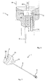
- Fig. 1-3 show schematic sectional and perspective views of a first embodiment of a sensor device 1.
- Die Fig. 1 shows a sectional view through a sensor device 1, which is coupled to a trained as an alternating filter fluid filter 4.
- the Fig. 2 shows a section through an acting as a fire protection housing portion on the sensor device, and Fig. 3 a perspective view of the same.
- FIG. 1 In the upper area of the Fig. 1 schematically an exchange filter 4 is shown.
- the replaceable filter 4 is cylindrical and has in the orientation in Fig. 1 which the typical installation situation below, an opening 5 for connection of a sensor element 2.
- the replaceable filter 4 has, for example, a filter pot made of a metal material.
- the replaceable filter 4 serves to filter fuel and the separation of water from the fuel.
- a sensor device 2 is provided in order to detect the level or the presence of water.
- the sensor device 2 is housed in a usually made of plastic sensor housing 3 and extends with a probe 26 into the interior of the filter cup of the element. 4
- the sensor element 2 is fluid-tightly connected to the housing of the replaceable filter 4.
- a sealing ring 7 is provided, which in particular extends an axial sealing action along the central axis A of the resulting filter arrangement with the sensor device 1.
- a threaded piece 6 may be provided or other connecting means, which are not shown here.
- the sensor element 3 supplies sensor signals to an evaluation device via a connection cable 8, which extends laterally outwards here, and a plug connector 9 connected thereto.
- a connection cable 8 which extends laterally outwards here, and a plug connector 9 connected thereto.
- This can be, for example, a vehicle electronics or evaluation circuit. It is also conceivable that the sensor device 1 supplies signals to a vehicle bus, such as a CAN bus.
- the sensor element 2 is surrounded to the outside by a fire protection housing 10, which is designed sleeve or cup-shaped.
- the housing is in Fig. 3 shown in perspective and includes a lower fire protection housing part 10 which is configured cup or cup-shaped.
- An upper transition piece 18 is provided with a passage 19 for the connection cable 8 and conforms to the contour of the lower region of the replaceable filter 4. This can be seen in particular in Fig. 1 ,
- the fire protection housing 10 is fastened with a clamp 15 and one or two holding strips 17 to the replaceable filter 4.
- a clamp 15 designed as a hose clamp clamp 15 is fastened with a screw 16.
- a drain or drain pipe 14 is provided on the underside, can run through the present in the interior of the fire enclosure 10 liquid.
- the process 14 is designed bent away laterally bent. As a result, flames can hardly or not penetrate through the bent pipe or the drain 14.
- Fig. 1 dashed a view is indicated in the fire protection housing 10.
- the Fig. 2 shows a longitudinal section through the fire protection housing 10, in which the sensor element 2 is received.
- the fire protection housing 10 is provided with a fire protection material 11 which surrounds the sensor element 2 in the manner of a cup.
- the fire protection material 11 adjoins the underside of the replaceable filter 4.
- a cavity 13 is present between the sensor housing 3 and the inside 12 of the fire protection housing 10.
- the cavity 13 or gap serves in case of fire as further isolation.
- the fire protection material 11 which is shown hatched, includes, for example, a mineral, a ceramic potting compound or fiberglass material, which withstands high temperatures and flames. One can also speak of a Flammtikumhüllung the sensor element 2.
- the fire protection material 11 may comprise a fire protection foam, which swells or expands when exposed to heat and thus keeps away from the outside entering flames or heat from the sensor element or the seal 7.
- the sensor device 1 is in particular encased in such a way with the fire protection housing 10 that a flame retardance test according to the above-mentioned regulations is passed. In other words, no filter fluid will escape from the interior of the replaceable filter 4 even after 30 minutes of flame exposure or an increase in temperature to above 850 ° C.
- materials having a melting point of less than about 930 ° C are coated with the fire protection material.
- the elements of the sensor device 1, which serve for fastening the fire protection material 11, are made for example of a metal material. These are in particular the clamp 15, the holding strips 19, the fire protection housing pot 10 and the discharge pipe 14.
- the proposed sensor device 1 makes it possible to operate appropriately equipped pre-filter arrangements for diesel engines in marine applications in watercraft.
- the actual sensor 2 can be made with a sensor housing 3 made of a polyamide material.
- Fig. 4 to 7 show schematic sectional and perspective views of an embodiment of a filter assembly and elements therein. It shows Fig. 4 a perspective view of the filter assembly, Fig. 5 a sectional view of the filter assembly, Fig. 6 a sectional arrangement of the sensor device used and Fig. 7 a perspective view of the embodiment of the sensor device.
- the in the Fig. 1-3 described elements of the sensor device can be used the same or similar here.
- the Fig. 4 shows a perspective view of a pre-filter assembly 100, in particular for use in diesel engines in or on watercraft.
- the filter arrangement 100 is equipped as a double filter with two exchangeable filters 4, 4 '.
- the filter arrangement has a filter head 27, which in particular comprises an inlet 20 for fluid to be cleaned, such as diesel fuel, and an outlet for purified fuel 21.
- a filter head 27 At the filter head 27 various fittings and fittings for the replaceable filters 4, 4 'are provided, which will not be discussed further below.
- a lever 23 allows the switching on and off of the two replaceable filters 4, 4 'independently. For example, in the lever position 23 to the left (see. Fig. 5 ) the left replaceable filter 4 is disconnected from the fuel and filter circuit and replaced.
- an exchange of individual replaceable filters can take place during the operation of the filter or the filter arrangement 100, without interrupting the operation.
- individual arrangements with or without a stopcock are also conceivable.
- replaceable filters are with the help of sealing rings 22, as in Fig. 5 is indicated, fluid-tightly connected to the filter head 27.
- sealing rings 22 as in Fig. 5 is indicated, fluid-tightly connected to the filter head 27.
- a fire protection foam 25 (shown in hatched form) surrounded, in particular embedded in the fire protection foam 25 recorded sensor element 2, which is coupled via a seal 7 to the replaceable filter 4.
- the fire protection foam 25 is preferably formed as intrinsically stable molded body.
- the fire protection foam is surrounded radially on the outside by a tubular housing designed as a fire protection housing 10, for example made of sheet steel, in particular stainless steel sheet.
- the fire protection housing 10 is connected to the replaceable filter 4, 4 'and slightly (about 0.3-2 mm) from the fire protection foam, so that it can be rotatably disposed within the fire protection housing 10.
- the rotation is desirable for mounting the fire protection foam sensor element unit and required for the regular discharge of the deposited in the replaceable filter 4 water, which takes place by dissolving the sensor element.
- the fire protection housing 10 is attached via a clamp 15 and screws 16 to the replaceable filter 4.
- the fire protection material 25 is a polyurethane foam, which is mixed, for example, with halogen-free fire protection additives such as Clariant Exolit OP 560 or Lanxess Uniplex FRP and has intumescent properties.
- the fire protection foam expands and deforms through the openings 24 provided in the fire protection housing 10. Due to the volume increase, the expanded fire protection foam protects the inner sensor element 2 from destruction for a certain period of time or burning. Before a flame reaches the sensor element 2 and the seal 7, the expanded fire protection foam 25 first burns off.
- a broken window is shown in dashed lines at the bottom left of the sensor device 1.
- the sensor element 2 comprises a connecting cable 8, which is guided eccentrically to the central axis A of the filter assembly 100 and the sensor element 2 down through the fire protection foam 25. Furthermore, a water or liquid drainage channel 14 is also guided eccentrically to the central axis A.
- a section of the left sensor and filter device 1 is shown in section.
- the sensor element 2 is equipped with a measuring sensor 26 which extends into the interior of the replaceable filter 4.
- the connection between the interior of the replaceable filter 4 and the sensor element 2 is fluid-tight.
- a water drainage channel 14 can be guided through the area of the fire protection material 25 to the outside.
- the fire protection material 25 catches, for example, when expanding to the in Fig. 5
- other means such as rough surfaces, projections or protruding sheet metal areas may be provided below the opening 24, which impedes falling or dripping of leaked fire protection foam.
- the Fig. 7 shows a perspective view of the sensor device 1, as in the embodiment of the filter assembly according to the 4 and 5 is used.
- the pot-shaped or cup-shaped, for example made of sheet metal fire protection housing 10 is preferably filled with the fire protection foam 25. Emerging from the field of fire protection foam can be seen in Fig. 7 the connection cable 8 with a connector 9 and the water drain 14th
- the center or symmetry axis A of the filter arrangement 100 and / or the sensor device 1 points vertically downwards, that is to say along the gravitational acceleration. This allows water to escape down through the drain 14. Due to the flame or fire protection material around the sensor device or the sensor element 3, which is usually made of plastic materials, a reliable operation can still be ensured over a certain period of time when a fire occurs in the vicinity of the filter arrangement 100.
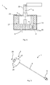
- the Fig. 7 and 8th show a third embodiment of a sensor device.
- 1 Fig. 8 is similar to a longitudinal section through the sensor device Fig. 6
- Fig. 9 is a perspective view of the sensor device.
- the fire protection casing of Sensor element 2 is effected by a ceramic potting compound 27, such as a refractory casting compound based on corundum with Kalziumaluminatitati.
- the fire protection material 27 has a weight fraction between 95% and 99% and a calcium oxide proportion between 1% and 5%.
- the ceramic fire protection material 27 is provided between two cover plates 29 made of an expanded graphite.
- the sensor arrangement 1 has no fire protection housing, but the ceramic fire protection material 27 stably holds on the sensor element 3, and is glued to the top and bottom, each with a cover plate 29.
- the cover plates have a thickness between 1 and 3 mm and the cylindrical fire protection ceramic has a height between 40 and 60 mm.
- the connection cable 8 and the connector 9 are sufficient, for example, DIN 5510, so that use of the sensor device 1 and the coupled thereto (not shown here) filter device can be used in particular in applications with special security requirements.
- the fire protection material is a stainless steel stainless steel material, which forms the housing 10 of the sensor element and this completely surrounds. Heat acting on the housing 10 can be dissipated partly via the sensor element to the operating fluid located in the interior of the filter 4 and the sensor, which delays the warm-up process in the event of a fire.
- the housing 10 is preferably provided in the region adjacent to the filter with an annular disc-shaped projection 111, the radial (ie at least 5 mm and preferably at least 10 mm) over the connection portion 112 of the sensor element with connecting thread (not shown) and seal 113 for sealing protrudes beyond the replaceable filter 4. In this way, flames reaching down from the bottom of the sensor arrangement can be deflected, so that the danger of direct contact of the connection area 113 with flames is markedly reduced.
- the proposed PreLine or pre-filter for fuels can be used.
- the filter arrangement, and in particular the sensor arrangement preferably corresponds to the fire resistance requirements set out in DIN EN ISO 7840 and / or ISO 19 921.
- a fluid-tightness at the transition between the sensor element 2 and the replaceable filter 4 over at least 30 minutes at a flame temperature of 700 - 900 ° C is achieved.
Landscapes
- Engineering & Computer Science (AREA)
- Chemical & Material Sciences (AREA)
- Chemical Kinetics & Catalysis (AREA)
- Mechanical Engineering (AREA)
- Combustion & Propulsion (AREA)
- Physics & Mathematics (AREA)
- Life Sciences & Earth Sciences (AREA)
- Health & Medical Sciences (AREA)
- General Engineering & Computer Science (AREA)
- General Physics & Mathematics (AREA)
- Oil, Petroleum & Natural Gas (AREA)
- Immunology (AREA)
- General Chemical & Material Sciences (AREA)
- Environmental & Geological Engineering (AREA)
- Pathology (AREA)
- Food Science & Technology (AREA)
- Medicinal Chemistry (AREA)
- Analytical Chemistry (AREA)
- Biochemistry (AREA)
- General Health & Medical Sciences (AREA)
- Acoustics & Sound (AREA)
- Manufacturing & Machinery (AREA)
- Filtering Materials (AREA)
- General Life Sciences & Earth Sciences (AREA)
- Geophysics (AREA)
- Fluid Mechanics (AREA)
- Investigating Or Analyzing Materials By The Use Of Fluid Adsorption Or Reactions (AREA)
- Fire Alarms (AREA)
Abstract
Description
- Die vorliegende Erfindung betrifft eine Sensoreinrichtung für eine Filteranordnung, wie für ein Betriebsmittelfilter in einem Fahrzeug. Ferner betrifft die Erfindung ein Verfahren zum Herstellen einer derartigen Sensoreinrichtung.
- In bestimmten Filteranwendungen ist die automatische Erfassung der voneinander getrennten Stoffe gewünscht. Beispielsweise werden bei Kraftstofffiltern, wie aus der
WO2012/025405A1 bekannt, insbesondere für Dieseleinspritzmotoren, Wasserbestandteile aus dem Dieselkraftstoff abgeschieden bzw. gefiltert. Das abgeschiedene Wasser wird in der Regel aufgefangen und dessen Füllstand mit Hilfe eines Feuchtigkeitssensors oder Wassersensors erkannt. Eine zuverlässige Funktion der Filteranordnung und/oder des entsprechenden Sensors auch unter besonderen Betriebsbedingungen ist dabei gewünscht. Die Sensoren oder Sensoreinrichtungen sind in der Regel getrennt von dem eigentlichen Filterelement vorgesehen. Beispielsweise kann ein Sensor mit einem in den Innenraum des Filterelements reichenden Messfühler mit dem Filterelement fluiddicht verbunden werden, so dass während des Betriebs Betriebsparameter des Filterelements erfasst werden können. Die eigentliche Sensoreinrichtung ist dabei außerhalb des Filterelementes angeordnet, beispielsweise angeschraubt, angeflanscht oder gesteckt. - Vor diesem Hintergrund liegt der vorliegenden Erfindung die Aufgabe zugrunde, eine verbesserte Sensoreinrichtung zu schaffen.
- Demgemäß wird eine Sensoreinrichtung für eine Filteranordnung vorgeschlagen, welche mindestens ein Sensorelement zum Erfassen eines Betriebsparameters für die Filteranordnung und ein Brandschutzmaterial, welches das Sensorelement zumindest teilweise umgibt, aufweist.
- Das Brandschutzmaterial schützt zum Beispiel das Sensorelement vor hohen Temperaturen, die eine Funktionsweise des Sensorelementes oder eine Ankopplung des Sensorelements mit der Filteranordnung beeinträchtigen können. In Ausführungsformen umgibt das Brandschutzmaterial das Sensorelement vollständig oder zu großen Teilen. Das Brandschutzmaterial kann auch so geformt sein, dass es einen Aufnahmebereich für das Sensorelement umfasst.
- Ein Brandschutzmaterial schirmt dabei von außen auf die Filteranordnung einwirkende Flammen oder Hitze in Folge eines Brandes auf das Sensorelement derart ab, dass bei einem vorgegebenen Zeitraum und bei vorgegebenen Flammtemperaturen die Funktion des Sensorelements und/oder eine Abdichtung des Sensorelements mit dem eingesetzten Filter unbeeinträchtigt bleibt. Ein Betriebsparameter ist beispielsweise das Vorliegen von Wasser in oder an der Filteranordnung. Denkbar ist jedoch auch die Ausgestaltung des Sensorelements zum Erfassen von Fluiden, wie Gasen oder Flüssigkeiten, Temperaturen, Drücken, elektrischen Leitwerten oder dgl.. Das Sensorelement ist insbesondere ein Wassersensor.
- In Ausführungsformen eignet sich die Sensoreinrichtung insbesondere für eine Filteranordnung, die zum Filtern von Betriebsmitteln in Fahrzeugen, wie Kraftfahrzeugen, Wasserfahrzeugen, Schienenfahrzeugen. stationären Stromerzeugern oder Fluggeräten, eingerichtet sind. Die Sensoreinrichtung ist insbesondere in oder an einem Filter wie einem Kraftstofffilter, einem Diesel-Kraftstofffilter für Diesel-Einspritzmotoren, angebracht. Man kann auch von Preline- oder Vorfiltern sprechen, die als Wechselfilter zur Partikel- und Wasserabscheidung von Kraftstoffen ausgestaltet sind. Als Wechselfilter werden im Ganzen austauschbar an einen Filterkopf montierbare Filter mit einem geschlossenen, meist aus Metall ausgeführten Gehäuse und einem darin angeordneten Filterkörper bezeichnet. Diese Filter sind auch als Spin-On Filter bekannt, da sie meist mittels eines Gewindes an den Filterkopf montierbar sind.
- In Ausführungsformen umfasst das Brandschutzmaterial ein intumeszierendes Material. Intumeszierende Materialien expandieren bei thermischer Beanspruchung bzw. schäumen auf und bilden eine dicke wärme- und flammenisolierende Schutzschicht. Intumeszierende Materialien sind auch als Brandschutzschäume bekannt. Als Brandschutzmaterial kommt insbesondere ein Polyurethanschaum in Frage, welcher mit Brandschutzadditiven versetzt ist. Das Brandschutzmaterial kann als Formteil in einer geeigneten Geometrie in der Sensoreinrichtung vorliegen. Es ist auch möglich, dass das Sensorelement mit entsprechendem Schaummaterial umschäumt ist. Bevorzugt weist das intumeszierende Material eine Dichte von kleiner 1000 kg/m3, besonders bevorzugt kleiner 400 kg/m3 auf.
- In weiteren Ausführungsformen umfasst das Brandschutzmaterial ein flammbeständiges Faser-material. Es sind beispielsweise Glasfilamentgewebe bekannt, die als Hitzeschilde verwendet werden können. Das Brandschutzmaterial kann zum Beispiel Silikatglasfasern umfassen, die Filamentdurchmesser von > 6 µm haben. Insbesondere Mineral- oder Glasfasermaterialien sind temperaturbeständig, in der Regel bis zu 1.000°C, und haben gute Isoliereigenschaften. Insbesondere Nadelmatten als Brandschutzmaterialien sind nicht brennbar und haben eine gute Vibrationsbeständigkeit. Ein Fasermaterial umfassendes Brandschutzmaterial kann als Formteil um das jeweilige Sensorelement gefertigt sein. Es ist möglich, das Brandschutzmaterial mit Befestigungsmitteln, wie Schellen, Gehäuseteilen, Netzen oder anderen ein räumliches Fixieren ermöglichenden Mitteln an oder um das Sensorelement zu befestigen.
- Das Brandschutzmaterial kann ferner ein Keramikmaterial aufweisen. Keramik kann beispielsweise als Vergussmasse eingesetzt werden und das Sensorelement zumindest teilweise umschließen. Das Keramikmaterial weist insbesondere eine Aluminium- und/ oder Kalziumverbindung auf. Als Keramikmaterialien kommen in Frage: Korund mit Kalziumaluminatbindung, Aluminiumoxid, Kalziumoxid, Magnesiumoxid, Eisenoxid sowie Mischungen der vorgenannten Materialien.
- In einer Ausführungsform ist das Brandschutzmaterial ein Edelstahlmaterial, welches das Gehäuse des Sensorelementes bildet und dieses vollständig umgibt. Auf das Gehäuse einwirkende Wärme kann teilweise über das Sensorelement an das im Inneren des Filters und des Sensors befindliche Wasser abgeführt werden, was den Aufwärmvorgang im Brandfalle verzögert. Das Gehäuse ist dabei bevorzugt im an den Filter angrenzenden Bereich mit einer ringscheibenförmigen Auskragung versehen, die radial deutlich (d.h. mindestens 5 mm und bevorzugt mindestens 10 mm) über den Anschlussbereich des Sensorelementes mit Anschlussgewinde und Dichtung hinausragt. Auf diese Weise können Flammen abgelenkt werden, so dass die Gefahr eines direkten Kontaktes des Anschlussbereiches mit Flammen deutlich verringert wird.
- In Ausführungsformen ist an das Brandschutzmaterial wenigstens eine Deckplatte angebracht, Beispielsweise kann das Brandschutzmaterial zwischen zwei Deckplatten angeordnet sein. Als Deckplattenmaterial kann ein Kohlenstoffmaterial eingesetzt werden. Es kommen insbesondere Carbonfaser- oder Polyacrylnitril-(PAN)-Fasermaterialien als Deckplattenmaterial in Frage. Die Dicke der Deckplatte ist beispielsweise zwischen 1 und 3 mm. Blähgraphit schäumt zum Beispiel bereits ab 145°C auf und expandiert. Graphit hat insbesondere den Vorteil, dass es alterungsbeständig, wasserbeständig und UV-beständig ist.
- In weiteren Ausführungsformen umfasst das Brandschutzmaterial und/oder das Deckplattenmaterial ein Blähgraphit.
- In Ausführungsformen ist ein zylinderförmiges Brandschutzmaterial zwischen zwei Deckplatten, die die Deckflächen bilden vorgesehen.
- In Ausführungsbeispielen ist das Sensorelement von einem umschließenden Brandschutzgehäuse umgeben. Das Brandschutzgehäuse ist zur Aufnahme des Brandschutzmaterials um das Sensorelement herum ausgestaltet. Beispielsweise kann das Sensorelement einerseits an die Filteranordnung oder einen Filter grenzen und andererseits von einem Brandschutzgehäuse umgeben sein, welches im Falle einer Flammeneinwirkung von außen Schutz bietet. Das Brandschutzgehäuse kann aus einem Metallwerkstoff gefertigt sein. Das Brandschutzgehäuse ist zum Beispiel mit einem Handhabungsabschnitt ausgestattet, um eine Einheit aus dem Sensorelement, dem Brandschutzmaterial und dem Gehäuse von dem Filter der Filteranordnung zu trennen.
- In Ausführungsformen hat das Gehäuse Öffnungen. Durch die Öffnungen kann beispielsweise im Brandfall aufschäumendes Material unter einer Volumenvergrößerung heraustreten und somit das Sensorelement besser schützen. Es ist auch möglich, dass innerhalb des Brandschutzgehäuses das Sensorelement und das Brandschutzmaterial derart miteinander verbunden sind, dass eine zerstörungsfreie Lösbarkeit der Teile voneinander unmöglich ist.
- In Ausführungsformen der Sensoreinrichtung ist zwischen dem Brandschutzmaterial und dem Sensorelement ein Hohlraum vorgesehen. Dieser Hohlraum oder ein Spalt zwischen der äußeren Oberfläche des Sensorelements und dem Brandschutzmaterial führt zu einer verbesserten Isolation nach außen hin.
- Die Sensoreinrichtung kann in Ausführungsformen ein Sensorelement umfassen, bei dem mindestens eine Anschlussleitung zum Übermitteln von Sensorsignalen vorgesehen ist. Die Anschlussleitung ist dabei wenigstens teilweise durch das Brandschutzmaterial nach außen geführt. Die Anschlussleitung ist beispielsweise ein Metalldraht, der mit einer Kunststoffisolation versehen ist. Die Anschlussleitung ist insbesondere ein Kabel in flammgeschützter Ausführung. Vorzugsweise entspricht das Kabel DIN 5510 mit Brandschutzstufe 1, 2, 3 oder 4.
- Die Sensoreinrichtung ist in Ausführungsformen derart mit einem Brandschutzmaterial ausgestattet, dass das Sensorelement einer Beflammung der Sensoreinrichtung über einen vorgegebenen Zeitraum bei einer vorgegebenen Temperatur widersteht. Denkbar ist beispielsweise, dass der vorgegebene Zeitraum mindestens 20, vorzugsweise mindestens 30 Minuten und noch bevorzugter 40 Minuten beträgt. Die Flammtemperatur ist beispielsweise mindestens 700°C, vorzugsweise 800°C und weiter bevorzugt 900°C. Es ist insbesondere denkbar, dass die Sensoreinrichtung eingerichtet ist, eine Feuerwiderstandsprüfung nach ISO 7840, ISO 19 921 oder nach Vorschriften der Schifffahrts-Klassifikationsgesellschaften zu bestehen.
- Die Sensoreinrichtung für die Filteranordnung ist dabei insbesondere derart ausgestaltet, dass an einer Verbindung zwischen dem Sensorelement und der Filteranordnung, wie beispielsweise einem Filter oder Wechselfilter, keine Undichtigkeit auftritt. Eine Kopplung zwischen der Filteranordnung und dem Sensorelement ist vorzugsweise derart fluiddicht, dass bei Druckunterschieden im einstelligen bar-Bereich keine Leckage auftritt.
- Es wird ferner eine Filteranordnung mit einem Filter, insbesondere einem Wechselfilter, zum Filtern eines Fluids mit einer, wie vorbeschriebenen Sensoreinrichtung vorgeschlagen. Das Sensorelement ist dabei fluiddicht an dem Filter angebracht.
- Vorzugsweise ist eine Dichtungseinrichtung, beispielsweise in der Art eines Dichtungsrings, zwischen dem Sensorelement und dem Filter vorgesehen.
- Die Filteranordnung ist insbesondere zum Einsatz in Wasser- und Schienenfahrzeugen und zum Filtern von Kraftstoff für einen Verbrennungsmotor ausgestaltet. Das Sensorelement dient dabei dem Detektieren von Wasser in einem Aufnahmeraum des Filters oder der Filteranordnung.
- Die Filteranordnung kann in Ausführungsformen eine Halteeinrichtung für den Filter, das Brandschutzgehäuse und/oder eines expandierenden Brandschutzmittels umfassen. Als Halteeinrichtung kommen insbesondere Schellen, Stege, Wülste, Rinnen, Öffnungen oder Hinterschnitte in Frage. Beispielsweise kann ein Brandschutzgehäuse für das Sensorelement mit Hilfe einer Schelle und einem oder mehreren Haltelaschen am Filter und/oder am Filterkopf befestigt sein.
- Schließlich wird ein Verfahren zum Herstellen einer Sensoreinrichtung, wie zuvor beschrieben, vorgeschlagen. Dabei wird ein Sensorelement mit einem (zunächst) fluiden Brandschutzmaterial wenigstens teilweise ummantelt. Das Brandschutzmaterial ist in einem abgebundenen verfestigten Zustand intumeszierend.
- Das Verfahren eignet sich insbesondere zum einfachen Herstellen von Sensoreinrichtungen, die Anforderungen an feuerwiderstandsfähige Systeme, insbesondere in Wasser- und Schienenfahrzeugen, genügen. In Ausführungsformen wird beispielsweise das Sensorelement mit einem Brandschutzschaum umgossen oder umspritzt. Denkbar ist das Bereithalten eines becherförmigen Brandschutzgehäuses, welches mit nicht abgebundenem Brandschutzmaterial verfüllt ist und das Sensorelement hineingesteckt wird. Ferner ist denkbar, eine Gießform bereitzuhalten, den Sensor in der Form zu positionieren und anschließend Brandschutzschaummasse in die Gießform einzudosieren, der beim Aufschäumen das Sensorelement sowie besonders bevorzugt auch den an das Sensorelement angrenzenden Bereich eines Anschlusskabels und eines Wasserablaufrohrs für im Filter abgeschiedenes Wasser umschließt und sich mit diesen verbindet. Bevorzugt ist der Brandschutzschaum nach dem Aushärten derart drehmomentfest (für bei Handbedienung üblicherweise auftretende Momente) mit dem Sensorelement verbunden, dass das Sensorelement durch Drehung am Brandschutzschaum in ein dafür am (Wechsel-)filter vorgesehenes Gewinde einschraubbar ist. Dazu können am Sensorelement außen bevorzugt Formschlusselemente vorgesehen sein. Beispielsweise kann das Sensorelement an seiner Außenseite (radial außen in Bezug auf die Mittelachse) eine polygonale Form aufweisen oder mit Rippen, Rändeln oder sonstigen zur Drehmomentübertragung geeigneten Strukturen versehen sein, die vom Brandschutzschaum formschlüssig umgeben sind. Bevorzugt ragt das Wasserablaufrohr räumlich unten aus dem Brandschutzschaum heraus. Dies erleichtert sowohl Bedienung als auch Herstellung.
- In Ausführungsformen der Filteranordnung hat der Filter einen Einlass und einen Auslass und dient dem Filtern von Betriebsmitteln für Verbrennungsmotoren. Das der Filter kann eine zylinderförmige Form haben und in bestimmungsgemäßem Einbau an seiner Unterseite eine Wasserablassöffnung sowie einen Anschluss für ein Sensorelement.
- Ein Gehäuse des Wechselfilters, bzw. des Filters ist beispielsweise aus feuerfestem Material mit einem Schmelzpunkt größer 900°C, wie einem Metallwerkstoff, gefertigt. Darüber hinaus kann die Filteranordnung beispielsweise in der Art eines Vorfiltersystems mit einem Filterkopf, der optional eine Pumpe, einen Heizelement und Schlauchanschlüsse für Ein- und Auslass umfasst, ausgeführt sein. Die Filteranordnung erfüllt insbesondere eine Vorfilterfunktion mit einer Wasserabscheidung. Die Filteranordnung wird mit einem Betriebsdruck von -1 bis 7 bar oder 3 bis 5 bar betrieben. Dementsprechend sind fluiddichte Übergänge zwischen Filter, Filterkopf und dem angeschlossenen Sensorelement für Über- oder Unterdrücke bis 8 bar ausgelegt.
- Ein entsprechender Filter ist mit einem Filterkörper aus einem Filtermedium ausgestattet. Das Filtermedium kann ein flächiges Material sein, das gefaltet oder wellenförmig ausgebildet ist. Als Faltungen sind beispielsweise Zickzack- oder W-Faltungen bekannt. Das Filtermedium kann geprägt und anschließend an Prägekanten unter Ausbildung von Faltkanten scharfkantig gefaltet sein. Als Ausgangsmaterial kann ein flächiger Filtermaterialbogen dienen, welcher entsprechend umgeformt wird. Es kann ein Endlosfaltenbalg ausgebildet sein.
- Das Filtermedium ist beispielsweise ein Filtergewebe, ein Filtergelege oder ein Filtervlies. Insbesondere kann das Filtermedium in einem Spinnvlies- oder Meltblown-Verfahren hergestellt sein. Weiter kann das Filtermedium verfilzt oder genadelt sein. Das Filtermedium kann Naturfasern, wie Baumwolle, oder Kunstfasern, beispielsweise aus Polyester, Polyvinylsulfit oder Polytetrafluorethylen, aufweisen. Die Fasern können bei der Verarbeitung in, schräg und/oder quer zur Maschinenrichtung orientiert sein. Das Filtermedium kann ein- oder mehrlagig sein. Das zu filternde Medium ist beispielsweise Luft. Ein gasförmiges Medium bzw. Luft umfasst hier auch Gas- bzw. Luftfeststoffgemische und/oder Gas- bzw. Luft-Flüssigkeitsgemische. Genauso sind Betriebsflüssigkeiten, wie Kraftstoffe, Schmiermittel, Harnsäurelösungen und dgl. denkbar, die zu reinigen sind.
- Der Filter kann in Personenkraftwägen, Lastkraftwägen, Baumaschinen, Wasserfahrzeugen, Schienenfahrzeugen, Luftfahrzeugen sowie allgemein in der Klimatechnik, insbesondere in Heiz-Klimageräten, in Haushaltsgeräten, in Brennstoffzellen oder in der Gebäudetechnik Anwendung finden. Diese Fahrzeuge können elektrisch und/oder mittels Kraftstoff (insbesondere Benzin, Diesel oder Erdgas) betrieben werden. Im Hinblick auf die Gebäudetechnik kommen insbesondere stationäre Anlagen zur Behandlung von Luft, beispielsweise für die stationäre Stromerzeugung in Betracht.
- Weitere mögliche Implementierungen der Erfindung umfassen auch nicht explizit genannte Kombinationen von zuvor oder im Folgenden bezüglich der Ausführungsbeispiele beschriebenen Merkmale oder Verfahrensschritte. Dabei wird der Fachmann auch Einzelaspekte als Verbesserungen oder Ergänzungen zu der jeweiligen Grundform der Sensoreinrichtung oder des Filters hinzufügen.
- Weitere Ausgestaltungen der Erfindung sind Gegenstand der Unteransprüche sowie der im Folgenden beschriebenen Ausführungsbeispiele. Im Weiteren wird die Erfindung anhand von Ausführungsbeispielen unter Bezugnahme auf die beigelegten Figuren näher erläutert.
- Es zeigt dabei:
- Fig. 1 - 3:
- schematische Schnitt- und Perspektivdarstellungen einer ersten Ausführungsform einer Sensoreinrichtung;
- Fig. 4 - 7:
- schematische Schnitt- und Perspektivdarstellungen einer Ausführungsform einer Filteranordnung mit einer zweiten Ausführungsform einer Sensoreinrichtung;
- Fig. 8 und 9:
- schematische Schnitt- und Perspektivdarstellungen einer dritten Ausführungsform einer Sensoreinrichtung; und
- Fig. 10
- eine schematische Teil-Schnittdarstellung einer vierten Ausführungsform einer Sensoreinrichtung.
- Im Folgenden werden Ausführungsformen von Filteranordnungen und Sensoreinrichtungen anhand von Vorfiltern für Dieselkraftstoff beschrieben. Dabei ist insbesondere ein Wassersensor als Sensorelement angegeben. An die Ausführungsbeispiele angelehnt können andere Filteranordnungen mit abweichenden Betriebsmitteln, Filtermedien oder Sensoren eingesetzt werden.
-
Fig. 1 - 3 zeigen schematische Schnitt- und Perspektivdarstellungen einer ersten Ausführungsform einer Sensoreinrichtung 1. DieFig. 1 zeigt dabei eine Schnittansicht durch eine Sensoreinrichtung 1, welche an einen als Wechselfilter ausgebildeten Fluidfilter 4 gekoppelt ist. DieFig. 2 zeigt einen Schnitt durch einen als Brandschutzgehäuse wirkenden Abschnitt an der Sensoreinrichtung, undFig. 3 eine perspektivische Darstellung desselben. - Im oberen Bereich der
Fig. 1 ist schematisch ein Wechselfilter 4 dargestellt. Der Wechselfilter 4 ist zylindrisch ausgeführt und hat in der Orientierung inFig. 1 , welche die typische Einbausituation widerspiegelt, unten eine Öffnung 5 zum Anschluss eines Sensorelements 2. Der Wechselfilter 4 hat dabei beispielsweise einen Filtertopf aus einem Metallwerkstoff. Das Wechselfilter4 dient dabei dem Filtern von Kraftstoff und dem Abscheiden von Wasser aus dem Kraftstoff. - Beim Betrieb des Wechselfilter4 sammelt sich im unteren Bereich abgeschiedenes Wasser als Flüssigkeit. Um den Füllstand bzw. das Vorliegen von Wasser zu erkennen, ist eine Sensoreinrichtung 2 vorgesehen. Die Sensoreinrichtung 2 ist in einem meist aus Kunststoff gefertigten Sensorgehäuse 3 untergebracht und reicht mit einem Messfühler 26 in den Innenraum des Filtertopfes des Elementes 4.
- Das Sensorelement 2 ist fluiddicht mit dem Gehäuse des Wechselfilters 4 verbunden. Dazu ist ein Dichtring 7 vorgesehen, der insbesondere eine axiale Dichtwirkung entlang der Mittelachse A der sich ergebenden Filteranordnung mit der Sensoreinrichtung 1 erstreckt. Alternativ kann auch eine Dichtung in radialer Richtung oder schräg mit radialem und axialem Anteil erfolgen. Zum Verbinden des Sensorelementes 2 mit dem Wechselfilter4 kann ein Gewindestück 6 vorgesehen sein oder andere Verbindungsmittel, die hier nicht weiter dargestellt sind. Beim Betrieb des Filters bzw. Wechselfilters 4 entstehen Drücke von bis zu 8 bar, d.h. der Abschluss des Wechselfilters 4 an der Öffnung 5 mit Hilfe des Sensorelements 2 widersteht diesen Drücken.
- Das Sensorelement 3 liefert über ein Anschlusskabel 8, das hier seitlich nach außen reicht, und einem daran angeschlossenen Steckverbinder 9 Sensorsignale an eine Auswerteeinrichtung. Dies kann beispielsweise eine Fahrzeugelektronik oder Auswerteschaltung sein. Es ist auch denkbar, dass die Sensoreinrichtung 1 Signale an einen Fahrzeugbus, wie beispielsweise einen CAN-Bus, liefert.
- Das Sensorelement 2 ist nach außen von einem Brandschutzgehäuse 10 umgeben, das hülsen- oder topfförmig ausgestaltet ist. Das Gehäuse ist in
Fig. 3 perspektivisch dargestellt und umfasst einen unteren Brandschutzgehäuseteil 10, der becher- oder topfförmig ausgestaltet ist. Ein oberes Übergangsstück 18 ist mit einem Durchgang 19 für das Anschlusskabel 8 versehen und schmiegt sich an die Kontur des unteren Bereichs des Wechselfilters 4 an. Dies erkennt man insbesondere inFig. 1 . - Das Brandschutzgehäuse 10 ist mit einer Schelle 15 und einem bzw. zwei Haltestreifen 17 an das Wechselfilter 4 befestigt. Dazu wird die als Schlauchschelle ausgestaltete Schelle 15 mit einem Schraubmittel 16 befestigt. An dem Brandschutzgehäusetopf 10 ist unterseitig ein Ablauf oder Ablaufrohr 14 vorgesehen, durch den im Inneren des Brandschutzgehäuses 10 vorliegende Flüssigkeit ablaufen kann. Der Ablauf 14 ist dabei gekröpft seitlich weggebogen gestaltet. Dadurch können potenziell Flammen kaum oder nicht durch die gekröpfte Rohrleitung bzw. den Abfluss 14 eindringen.
- In
Fig. 1 ist gestrichelt eine Sicht in das Brandschutzgehäuse 10 angedeutet. DieFig. 2 zeigt einen Längsschnitt durch das Brandschutzgehäuse 10, in dem das Sensorelement 2 aufgenommen ist. Das Brandschutzgehäuse 10 ist dabei mit einem Brandschutzmaterial 11 versehen, das in der Art eines Bechers das Sensorelement 2 umschließt. Oberseitig grenzt das Brandschutzmaterial 11 an die Unterseite des Wechselfilters 4. Im eingebauten Zustand erkennt man inFig. 1 , dass ein Hohlraum 13 zwischen dem Sensorgehäuse 3 und der Innenseite 12 des Brandschutzgehäuses 10 vorliegt. Der Hohlraum 13 oder Spalt dient im Brandfall als weitere Isolation. - Das Brandschutzmaterial 11, welches schraffiert dargestellt ist, umfasst beispielsweise ein Mineral, eine keramische Vergussmasse oder Glasfasermaterial, welches hohen Temperaturen und Beflammungen widersteht. Man kann auch von einer Flammschutzumhüllung des Sensorelementes 2 sprechen.
- Alternativ oder zusätzlich kann das Brandschutzmaterial 11 einen Brandschutzschaum umfassen, der bei Wärmeeinwirkung aufquillt bzw. expandiert und damit von außen eintretende Flammen bzw. Hitze von dem Sensorelement bzw. der Dichtung 7 fernhält. Die Sensoreinrichtung 1 ist insbesondere derart mit dem Brandschutzgehäuse 10 ummantelt, dass eine Flammschutzprüfung nach den oben genannten Vorschriften bestanden wird. D.h., aus dem Inneren des Wechselfilters 4 tritt auch nach 30-minütiger Flammeneinwirkung bzw. einer Temperaturerhöhung auf über 850°C keine Filterfluid aus.
- Bei den Ausführungsformen sind insbesondere Materialien, die einen Schmelzpunkt von kleiner als etwa 930°C haben, mit dem Brandschutzmaterial ummantelt. Die Elemente der Sensoreinrichtung 1, welche zum Befestigen des Brandschutzmaterials 11 dienen, sind beispielsweise aus einem Metallwerkstoff gefertigt. Dies sind insbesondere die Schelle 15, der Haltestreifen 19, der Brandschutzgehäusetopf 10 sowie das Ablassrohr 14.
- Die vorgeschlagene Sensoreinrichtung 1 ermöglicht insbesondere einen Betrieb entsprechend ausgestatteter Vorfilteranordnungen für Dieselmotoren in Marineanwendungen in Wasserfahrzeugen. Der eigentliche Sensor 2 kann dabei mit einem Sensorgehäuse 3 aus einem Polyamidmaterial gefertigt sein.
-
Fig. 4 bis 7 zeigen schematische Schnitt- und Perspektivdarstellungen einer Ausführungsform einer Filteranordnung und Elemente darin. Dabei zeigtFig. 4 eine perspektivische Ansicht der Filteranordnung,Fig. 5 eine Schnittansicht der Filteranordnung,Fig. 6 eine Schnittanordnung der eingesetzten Sensoreinrichtung undFig. 7 eine perspektivische Ansicht der Ausführungsform der Sensoreinrichtung. Die in denFig. 1 -3 beschriebenen Elemente der Sensoreinrichtung können gleich oder ähnlich auch hier eingesetzt werden. - Die
Fig. 4 zeigt eine perspektivische Darstellung einer Vorfilteranordnung 100, insbesondere zum Einsatz für Dieselmotoren in oder auf Wasserfahrzeugen. Die Filteranordnung 100 ist als Doppelfilter mit zwei Wechselfiltern 4, 4' ausgestattet. Die Filteranordnung hat dabei einen Filterkopf 27, der insbesondere einen Einlass 20 für zu reinigendes Fluid, wie Dieselkraftstoff, und einen Auslass für gereinigten Kraftstoff 21 umfasst. An dem Filterkopf 27 sind verschiedene Armaturen und Anschlussstücke für die Wechselfiltere 4, 4' vorgesehen, auf die im Folgenden nicht weiter eingegangen wird. - Ein Hebel 23 ermöglicht das Zu- und Abschalten der beiden Wechselfilter 4, 4' unabhängig voneinander. Beispielsweise kann bei der Hebelstellung 23 nach links (vgl.
Fig. 5 ) der linke Wechselfilter 4 vom Kraftstoff und Filterkreislauf abgekoppelt und ausgetauscht werden. Durch die zwei unabhängig voneinander betreibbaren Wechselfilter 4, 4' kann während des Betriebs des Filters bzw. der Filteranordnung 100 ein Austausch einzelner Wechselfilter erfolgen, ohne den Betrieb zu unterbrechen. Es sind jedoch auch Einzelanordnungen mit oder ohne Absperrhahn denkbar. - Die Wechselfilter sind mit Hilfe von Dichtringen 22, wie in
Fig. 5 angedeutet ist, an den Filterkopf 27 fluiddicht verbunden. Im Folgenden wird im Wesentlichen auf die linke mit dem Bezugszeichen 4 versehene Kombination aus Wechselfilter4 und Sensoreinrichtung 1 eingegangen. - In
Fig. 5 erkennt man ein von einem Brandschutzschaum 25 (schraffiert dargestelt) umgebenes, insbesondere in dem Brandschutzschaum 25 eingebettet aufgenommenes Sensorelement 2, das über eine Dichtung 7 an den Wechselfilter 4 gekoppelt ist. Der Brandschutzschaum 25 ist bevorzugt als eigenstabiler Formkörper ausgebildet. Der Brandschutzschaum ist radial außen von einem als Rohrzylinder ausgebildeten Brandschutzgehäuse 10, beispielsweise aus Stahlblech, insbesondere aus rostfreiem Edelstahlblech, umgeben. Das Brandschutzgehäuse 10 ist mit dem Wechselfilter 4, 4` verbunden und leicht (ca. 0,3-2 mm) vom Brandschutzschaum beabstandet, so dass dieser innerhalb des Brandschutzgehäuses 10 drehbar angeordnet werden kann. Die Drehbarkeit ist zur Montage der Brandschutzschaum-Sensorelement-Einheit wünschenswert und für das regelmäßige Ablassen des im Wechselfilter 4 abgeschiedenen Wassers erforderlich, welches durch Anlösen des Sensorelements erfolgt. Das Brandschutzgehäuse 10 ist über eine Schelle 15 und Schrauben 16 an den Wechselfilter 4 befestigt. Das Brandschutzmaterial 25 ist dabei ein Polyurethanschaum, der beispielsweise mit halogenfreien Brandschutzadditiven wie Clariant Exolit OP 560 oder Lanxess Uniplex FRP versetzt ist und intumeszierende Eigenschaften hat. Bei einer Beflammung von außen dehnt sich der Brandschutzschaum aus und verformt sich durch die im Brandschutzgehäuse 10 vorgesehenen Öffnungen 24 hinaus. Aufgrund der Volumenzunahme schützt der expandierte Brandschutzschaum das innenliegende Sensorelement 2 über einen gewissen Zeitraum vor Zerstörung bzw. Verbrennen. Bevor eine Flamme das Sensorelement 2 und die Dichtung 7 erreicht, brennt zunächst der expandierte Brandschutzschaum 25 ab. - In
Fig. 5 ist ein aufgebrochenes Fenster gestrichpunktet unten links an der Sensoreinrichtung 1 dargestellt. Das Sensorelement 2 umfasst ein Anschlusskabel 8, das exzentrisch zur Mittelachse A der Filteranordnung 100 und des Sensorelements 2 nach unten durch den Brandschutzschaum 25 geführt ist. Ferner ist ein Wasser- bzw. Flüssigkeitsablasskanal 14 ebenfalls exzentrisch zur Mittelachse A geführt. - In
Fig. 6 ist ein Ausschnitt der linken Sensor- und Filtereinrichtung 1 im Schnitt dargestellt. Das Sensorelement 2 ist mit einem Messfühler 26, der in den Innenraum des Wechselfilters 4 reicht, ausgestattet. Die Verbindung zwischen dem Innenraum des Wechselfilters 4 und dem Sensorelement 2 ist fluiddicht. Seitlich vom Sensorelement 2 kann ein Wasserablasskanal 14 durch den Bereich des Brandschutzmaterials 25 hindurch nach außen geführt sein. Das Brandschutzmaterial 25 verfängt sich beispielsweise beim Expandieren an den inFig. 5 als 24 bezeichneten Öffnungen des Brandschutzgehäuses 10. Ferner können weitere Mittel, wie beispielsweise raue Oberflächen, Auskragungen oder abstehende Blechbereiche unterhalb der Öffnung 24 vorgesehen sein, die ein Herabfallen oder Abtropfen von ausgetretenem Brandschutzschaum behindert. - Die
Fig. 7 zeigt eine perspektivische Darstellung der Sensoreinrichtung 1, wie sie im Ausführungsbeispiel für die Filteranordnung nach denFig. 4 und 5 eingesetzt ist. Das topf- oder becherförmige, beispielsweise aus Blech gefertigte Brandschutzgehäuse 10 ist vorzugsweise mit dem Brandschutzschaum 25 verfüllt. Aus dem Bereich des Brandschutzschaumes austretend sieht man inFig. 7 das Anschlusskabel 8 mit einem Steckverbinder 9 sowie den Wasserablass 14. - Bei bestimmungsgemäßem Gebrauch weist die Mittel- oder Symmetrieachse A der Filteranordnung 100 und/oder der Sensoreinrichtung 1 vertikal nach unten, also entlang der Erdbeschleunigung. Dadurch kann Wasser nach unten durch den Ablass 14 austreten. Aufgrund des Flamm- oder Brandschutzmaterials um die Sensoreinrichtung bzw. das meist aus Kunststoffmaterialien gebaute Sensorelement 3 kann über einen gewissen Zeitraum bei Auftreten eines Brandes in der Nähe der Filteranordnung 100 ein zuverlässiger Betrieb noch gewährleistet werden.
- Die
Fig. 7 und8 zeigen eine dritte Ausführungsform einer Sensoreinrichtung 1.Fig. 8 ist ein Längsschnitt durch die Sensoreinrichtung ähnlichFig. 6 , undFig. 9 ist eine perspektivische Darstellung der Sensoreinrichtung. Es sind im Wesentlichen die gleichen Elemente wie in der ersten und zweiten Ausführungsform vorhanden und mit den gleichen Bezugszeichen versehen, worauf hier nicht mehr explizit eingegangen wird. Die Brandschutzummantelung des Sensorelements 2 erfolgt durch eine keramische Vergussmasse 27, wie eine feuerfeste Gießmasse auf Basis von Korund mit Kalziumaluminatbindung. Das Brandschutzmaterial 27 hat zum Beispiel einen Gewichtsanteil zwischen 95% und 99% und einen Kalziumoxidanteil zwischen 1 % und 5%. Das keramische Brandschutzmaterial 27 ist zwischen zwei Deckplatten 29 aus einem Blähgraphit vorgesehen. - Die Sensoranordnung 1 hat kein Brandschutzgehäuse, sondern das keramische Brandschutzmaterial 27 hält stabil an dem Sensorelement 3, und ist nach oben und unten mit jeweils einer Deckplatte 29 beklebt. Die Deckplatten haben zum Beispiel eine Dicke zwischen 1 und 3 mm und die zylinderförmige Brandschutzkeramik hat eine Höhe zwischen 40 und 60 mm. Das Anschlusskabel 8 und der Steckverbinder 9 genügen zum Beispiel der DIN 5510, so dass ein Einsatz der Sensoreinrichtung 1 und der daran angekoppelten (hier nicht dargestellten) Filtereinrichtung in besonders in Anwendungen mit speziellen Sicherheitsanforderungen eingesetzt werden kann.
- In der in
Figur 10 gezeigten Ausführungsform einer Sensoranordnung 1 ist das Brandschutzmaterial ein rostfreies Edelstahlmaterial, welches das Gehäuse 10 des Sensorelementes bildet und dieses vollständig umgibt. Auf das Gehäuse 10 einwirkende Wärme kann teilweise über das Sensorelement an die im Inneren des Filters 4 und des Sensors befindliche Betriebsflüssigkeit abgeführt werden, was den Aufwärmvorgang im Brandfalle verzögert. Das Gehäuse 10 ist dabei bevorzugt im an den Filter angrenzenden Bereich mit einer ringscheibenförmigen Auskragung 111 versehen, die radial deutlich (d.h. mindestens 5 mm und bevorzugt mindestens 10 mm) über den Anschlussbereich 112 des Sensorelementes mit Anschlussgewinde (nicht gezeigt) und Dichtung 113 zur Abdichtung gegenüber dem Wechselfilter 4 hinausragt. Auf diese Weise können von räumlich unten an die Sensoranordnung heranreichende Flammen abgelenkt werden, so dass die Gefahr eines direkten Kontaktes des Anschlussbereiches 113 mit Flammen deutlich verringert wird. - Entgegen üblichen aus Kunststoff gefertigten Sensoren ergibt sich durch die Ummantelung mit einer Brandschutzschicht oder einem Brandschutzmaterial eine erweiterte Einsatzmöglichkeit. Insbesondere in Anwendungen, bei denen besondere Brandschutzanforderungen bestehen, wie beispielsweise im Marinebereich auf Schiffen, kann der vorgeschlagene PreLine- oder Vorfilter für Kraftstoffe eingesetzt werden. Die Filteranordnung, und insbesondere die Sensoranordnung, entspricht dabei vorzugsweise den in der DIN EN ISO 7840 und/oder ISO 19 921 dargelegten Anforderungen an die Feuerwiderstandsfähigkeit. Es wird insbesondere eine Fluiddichtigkeit am Übergang zwischen dem Sensorelement 2 und dem Wechselfilter 4 über wenigstens 30 min bei einer Flammtemperatur von 700 - 900°C erreicht.
- Obwohl die vorliegende Erfindung anhand bevorzugter Ausführungsbeispiele näher erläutert wurde, ist sie nicht darauf beschränkt, sondern vielfältig modifizierbar. "Ein" schließt vorliegend keine Vielzahl aus.
Claims (11)
- Sensoreinrichtung (1) für eine Filteranordnung (100), mit mindestens einem Sensorelement (2) zum Erfassen eines Betriebsparameters für die Filteranordnung (100), insbesondere zum Detektieren von Wasser, und mit einem Brandschutzmaterial (11, 25), welches das Sensorelement (2) zumindest teilweise umgibt.
- Sensoreinrichtung (1) nach Anspruch 1, wobei das Brandschutzmaterial (25) ein intumeszierendes Material umfasst.
- Sensoreinrichtung (1) nach Anspruch 1 oder 2, wobei das Brandschutzmaterial (11) ein flammbeständiges Fasermaterial umfasst.
- Sensoreinrichtung (1) nach einem der Ansprüche 1 bis 3, ferner mit einem das Sensorelement (2) umschließenden Brandschutzgehäuse (10) zur Aufnahme des Brandschutzmaterials (11, 25) um das Sensorelement (2) herum.
- Sensoreinrichtung (1) nach einem der Ansprüche 1 bis 4, wobei zwischen dem Brandschutzmaterial (11) und dem Sensorelement (2) ein Hohlraum (13) vorgesehen ist.
- Sensoreinrichtung (1) nach einem der Ansprüche 1 bis 5, wobei das Sensorelement (2) mindestens eine Anschlussleitung (8) zum Übermitteln von Sensorsignalen aufweist, wobei die Anschlussleitung (8) wenigstens teilweise durch das Brandschutzmaterial (11, 25) nach außen geführt ist.
- Sensoreinrichtung (1) nach einem der Ansprüche 1 bis 6, wobei das Brandschutzmaterial (11, 25) derart ausgestaltet ist, dass das Sensorelement (2) einer Beflammung der Sensoreinrichtung (1) über mindestens dreißig Minuten bei mindestens 800 °C widersteht.
- Filteranordnung (100) mit einem Filterelement (4) zum Filtern eines Fluids und einer Sensoreinrichtung (1) nach einem der Ansprüche 1 bis 7, wobei das Sensorelement (2), insbesondere mit Hilfe einer Dichtung (7), fluiddicht an das Filterelement (4) angebracht ist.
- Filteranordnung nach Anspruch 8, ferner mit einer Halteeinrichtung (15, 17) für das Filterelement (4), das Brandschutzgehäuse (10) und/oder eines expandierenden Brandschutzmaterials (11, 25).
- Verfahren zum Herstellen einer Sensoreinrichtung (1) nach einem der Ansprüche 1 bis 7, wobei ein Sensorelement (1) mit einem fluiden Brandschutzmaterial (25) wenigstens teilweise ummantelt wird, und das Brandschutzmaterial (25) in einem abgebundenen verfestigten Zustand intumeszierend ist.
- Verfahren nach Anspruch 10, wobei das fluide Brandschutzmaterial (25) ein Polyurethan-Werkstoff ist, der in flüssiger Form in einer Gießschale eindosiert wird, in welcher bereits das Sensorelement positioniert ist, wobei der Polyurethanwerkstoff beim Eindosieren und/oder beim Aufschäumen das Sensorelement umschließt und anschließend aushärtet, so dass das Sensorelement (1) formschlüssig und insbesondere Drehmomentfest ummantelt ist.
Applications Claiming Priority (1)
| Application Number | Priority Date | Filing Date | Title |
|---|---|---|---|
| DE102014008830.8A DE102014008830A1 (de) | 2014-06-20 | 2014-06-20 | Sensoreinrichtung, Filteranordnung und Verfahren zum Herstellen derselben |
Publications (1)
| Publication Number | Publication Date |
|---|---|
| EP2957758A1 true EP2957758A1 (de) | 2015-12-23 |
Family
ID=53002550
Family Applications (1)
| Application Number | Title | Priority Date | Filing Date |
|---|---|---|---|
| EP15164792.2A Withdrawn EP2957758A1 (de) | 2014-06-20 | 2015-04-23 | Sensoreinrichtung, Filteranordnung und Verfahren zum herstellen derselben |
Country Status (4)
| Country | Link |
|---|---|
| US (1) | US20150369788A1 (de) |
| EP (1) | EP2957758A1 (de) |
| KR (1) | KR20150146430A (de) |
| DE (1) | DE102014008830A1 (de) |
Families Citing this family (5)
| Publication number | Priority date | Publication date | Assignee | Title |
|---|---|---|---|---|
| CN110170199B (zh) * | 2014-07-23 | 2022-10-25 | 康明斯滤清系统知识产权公司 | 入口旁路流动管理系统和方法 |
| US11097210B2 (en) | 2017-09-20 | 2021-08-24 | Neapco Intellectual Property Holdings, Llc | Disposable filter including an integrated sensor assembly |
| US12072269B2 (en) * | 2019-03-29 | 2024-08-27 | Rosemount Inc. | Self-contained calibration apparatus for gas sensor |
| CN111766376B (zh) * | 2020-09-01 | 2021-02-26 | 东营玺诺石油科技有限公司 | 一种油田原油水含量检测用溶剂油加注器 |
| CN116141575B (zh) * | 2023-04-19 | 2023-09-19 | 西安感崆电子信息科技有限公司 | 一种线束传感器注塑模具及其制造方法 |
Citations (5)
| Publication number | Priority date | Publication date | Assignee | Title |
|---|---|---|---|---|
| US5599460A (en) * | 1993-08-13 | 1997-02-04 | Van Schoiack; Michael | Water/glycol sensor for use in oil systems |
| EP1277948A2 (de) * | 2001-07-20 | 2003-01-22 | Robert Bosch Gmbh | Kraftstofffilter |
| DE102007000045A1 (de) * | 2006-01-30 | 2007-09-13 | Denso Corp., Kariya | Gassensor mit verbesserter Hitzebeständigkeit |
| WO2012025405A1 (de) | 2010-08-26 | 2012-03-01 | Mann+Hummel Gmbh | Filter und verfahren zum herstellen desselben |
| WO2013135440A1 (de) * | 2012-03-16 | 2013-09-19 | Mann+Hummel Gmbh | Kraftstofffilter einer brennkraftmaschine und heiz-sensor-modul eines kraftstofffilters |
Family Cites Families (5)
| Publication number | Priority date | Publication date | Assignee | Title |
|---|---|---|---|---|
| DE10007980B4 (de) * | 2000-02-22 | 2007-07-12 | Hilti Ag | Zweikomponenten-Ortschaumsystem und dessen Verwendung zum Ausschäumen von Öffnungen zum Zwecke des Brandschutzes |
| ITMI20052378A1 (it) * | 2005-12-13 | 2007-06-14 | Controlcavi Ind S R L | Cavo elettrico resistente al fuoco con caratteristiche di sicurezza totale di funzionamento |
| DE102008034904A1 (de) * | 2008-07-26 | 2010-01-28 | Mahle International Gmbh | Moduleinsatz zum Einbau in einen Flüssigkeitsfilter |
| US20100117842A1 (en) * | 2008-11-13 | 2010-05-13 | Warning, Sa | Contaminant Detection Unit |
| FR2951452B1 (fr) * | 2009-10-16 | 2012-07-27 | Rhodia Operations | Article moule ignifuge a base de polyamide comprenant un revetement intumescent |
-
2014
- 2014-06-20 DE DE102014008830.8A patent/DE102014008830A1/de not_active Withdrawn
-
2015
- 2015-04-23 EP EP15164792.2A patent/EP2957758A1/de not_active Withdrawn
- 2015-06-17 US US14/742,161 patent/US20150369788A1/en not_active Abandoned
- 2015-06-18 KR KR1020150086576A patent/KR20150146430A/ko not_active Withdrawn
Patent Citations (5)
| Publication number | Priority date | Publication date | Assignee | Title |
|---|---|---|---|---|
| US5599460A (en) * | 1993-08-13 | 1997-02-04 | Van Schoiack; Michael | Water/glycol sensor for use in oil systems |
| EP1277948A2 (de) * | 2001-07-20 | 2003-01-22 | Robert Bosch Gmbh | Kraftstofffilter |
| DE102007000045A1 (de) * | 2006-01-30 | 2007-09-13 | Denso Corp., Kariya | Gassensor mit verbesserter Hitzebeständigkeit |
| WO2012025405A1 (de) | 2010-08-26 | 2012-03-01 | Mann+Hummel Gmbh | Filter und verfahren zum herstellen desselben |
| WO2013135440A1 (de) * | 2012-03-16 | 2013-09-19 | Mann+Hummel Gmbh | Kraftstofffilter einer brennkraftmaschine und heiz-sensor-modul eines kraftstofffilters |
Also Published As
| Publication number | Publication date |
|---|---|
| DE102014008830A1 (de) | 2015-12-24 |
| US20150369788A1 (en) | 2015-12-24 |
| KR20150146430A (ko) | 2015-12-31 |
Similar Documents
| Publication | Publication Date | Title |
|---|---|---|
| DE102014008830A1 (de) | Sensoreinrichtung, Filteranordnung und Verfahren zum Herstellen derselben | |
| EP2607761A1 (de) | Brandschutzmanschette | |
| WO2014029828A1 (de) | Filtereinrichtung, insbesondere zur gasfiltration | |
| DE202009019120U1 (de) | Hitzeschutz für temperaturempfindliche Bauteile | |
| EP1831511B1 (de) | Wabenkörper mit zumindest teilweise keramischer wabenstruktur und aufnahme für messfühler und verfahren zur herstellung eines solchen wabenkörpers | |
| WO2009019244A1 (de) | Filterelement, filtergehäuse und filteranordnung | |
| EP1648583A1 (de) | Ölfilteranordnung und filterelement | |
| DE102016202692A1 (de) | Verschlusssystem für einen Behälter | |
| DE102016010523B4 (de) | Filtergehäuse eines austauschbaren Filters, Filter und Filtervorrichtung | |
| DE102017206251B3 (de) | Wassertankeinrichtung für eine Brennkraftmaschine mit Wassereinspritzung | |
| WO2021009094A1 (de) | Fluidfilter für einen kraftwagen und filterkartusche für einen fluidfilter | |
| DE202005021558U1 (de) | Sammler für die flüssige Phase des Arbeitsmediums einer Klimaanlage | |
| EP1453574B1 (de) | Brandschutzablauf | |
| EP2953702B1 (de) | Flüssigkeitsfilter | |
| WO2018054862A1 (de) | Schraubenkompressor für ein nutzfahrzeug | |
| DE102013004865B4 (de) | Filtereinrichtung mit einem ringförmigen Filterelement | |
| DE102014015613A1 (de) | Hohlfilterelement und Filter mit einem Hohlfilterelement | |
| DE102016224139B4 (de) | Rundluftfilter und Luftreinigeranordnung für ein Fahrzeug mit dem Luftfilter | |
| DE102014005348B4 (de) | Filterelement eines Filters und Filter | |
| WO2002023019A1 (de) | Einrichtung zum behandeln von abgasen aus technischen verbrennungsprozessen | |
| DE102014002805A1 (de) | Fehlbetankungsschutz | |
| DE102008034435A1 (de) | Flammschutzeinrichtung für eine Rohrkupplung und Rohrkupplung | |
| DE102009029775B4 (de) | Abstandshalter für Filtertöpfe | |
| DE20019636U1 (de) | Airbagbaueinheit | |
| DE202014103537U1 (de) | Sensorvorrichtung zur Erfassung von Eigenschaften fluider Medien |
Legal Events
| Date | Code | Title | Description |
|---|---|---|---|
| PUAI | Public reference made under article 153(3) epc to a published international application that has entered the european phase |
Free format text: ORIGINAL CODE: 0009012 |
|
| AK | Designated contracting states |
Kind code of ref document: A1 Designated state(s): AL AT BE BG CH CY CZ DE DK EE ES FI FR GB GR HR HU IE IS IT LI LT LU LV MC MK MT NL NO PL PT RO RS SE SI SK SM TR |
|
| AX | Request for extension of the european patent |
Extension state: BA ME |
|
| 17P | Request for examination filed |
Effective date: 20160304 |
|
| RBV | Designated contracting states (corrected) |
Designated state(s): AL AT BE BG CH CY CZ DE DK EE ES FI FR GB GR HR HU IE IS IT LI LT LU LV MC MK MT NL NO PL PT RO RS SE SI SK SM TR |
|
| 17Q | First examination report despatched |
Effective date: 20160720 |
|
| STAA | Information on the status of an ep patent application or granted ep patent |
Free format text: STATUS: THE APPLICATION IS DEEMED TO BE WITHDRAWN |
|
| 18D | Application deemed to be withdrawn |
Effective date: 20161201 |