EP2957647A2 - Steel for cold working tool - Google Patents
Steel for cold working tool Download PDFInfo
- Publication number
- EP2957647A2 EP2957647A2 EP15171821.0A EP15171821A EP2957647A2 EP 2957647 A2 EP2957647 A2 EP 2957647A2 EP 15171821 A EP15171821 A EP 15171821A EP 2957647 A2 EP2957647 A2 EP 2957647A2
- Authority
- EP
- European Patent Office
- Prior art keywords
- steel
- die
- cold working
- working tool
- less
- Prior art date
- Legal status (The legal status is an assumption and is not a legal conclusion. Google has not performed a legal analysis and makes no representation as to the accuracy of the status listed.)
- Granted
Links
Images
Classifications
-
- C—CHEMISTRY; METALLURGY
- C22—METALLURGY; FERROUS OR NON-FERROUS ALLOYS; TREATMENT OF ALLOYS OR NON-FERROUS METALS
- C22C—ALLOYS
- C22C38/00—Ferrous alloys, e.g. steel alloys
- C22C38/18—Ferrous alloys, e.g. steel alloys containing chromium
- C22C38/40—Ferrous alloys, e.g. steel alloys containing chromium with nickel
- C22C38/42—Ferrous alloys, e.g. steel alloys containing chromium with nickel with copper
-
- C—CHEMISTRY; METALLURGY
- C21—METALLURGY OF IRON
- C21D—MODIFYING THE PHYSICAL STRUCTURE OF FERROUS METALS; GENERAL DEVICES FOR HEAT TREATMENT OF FERROUS OR NON-FERROUS METALS OR ALLOYS; MAKING METAL MALLEABLE, e.g. BY DECARBURISATION OR TEMPERING
- C21D1/00—General methods or devices for heat treatment, e.g. annealing, hardening, quenching or tempering
- C21D1/84—Controlled slow cooling
-
- C—CHEMISTRY; METALLURGY
- C21—METALLURGY OF IRON
- C21D—MODIFYING THE PHYSICAL STRUCTURE OF FERROUS METALS; GENERAL DEVICES FOR HEAT TREATMENT OF FERROUS OR NON-FERROUS METALS OR ALLOYS; MAKING METAL MALLEABLE, e.g. BY DECARBURISATION OR TEMPERING
- C21D6/00—Heat treatment of ferrous alloys
- C21D6/002—Heat treatment of ferrous alloys containing Cr
-
- C—CHEMISTRY; METALLURGY
- C22—METALLURGY; FERROUS OR NON-FERROUS ALLOYS; TREATMENT OF ALLOYS OR NON-FERROUS METALS
- C22C—ALLOYS
- C22C38/00—Ferrous alloys, e.g. steel alloys
- C22C38/001—Ferrous alloys, e.g. steel alloys containing N
-
- C—CHEMISTRY; METALLURGY
- C22—METALLURGY; FERROUS OR NON-FERROUS ALLOYS; TREATMENT OF ALLOYS OR NON-FERROUS METALS
- C22C—ALLOYS
- C22C38/00—Ferrous alloys, e.g. steel alloys
- C22C38/002—Ferrous alloys, e.g. steel alloys containing In, Mg, or other elements not provided for in one single group C22C38/001 - C22C38/60
-
- C—CHEMISTRY; METALLURGY
- C22—METALLURGY; FERROUS OR NON-FERROUS ALLOYS; TREATMENT OF ALLOYS OR NON-FERROUS METALS
- C22C—ALLOYS
- C22C38/00—Ferrous alloys, e.g. steel alloys
- C22C38/02—Ferrous alloys, e.g. steel alloys containing silicon
-
- C—CHEMISTRY; METALLURGY
- C22—METALLURGY; FERROUS OR NON-FERROUS ALLOYS; TREATMENT OF ALLOYS OR NON-FERROUS METALS
- C22C—ALLOYS
- C22C38/00—Ferrous alloys, e.g. steel alloys
- C22C38/04—Ferrous alloys, e.g. steel alloys containing manganese
-
- C—CHEMISTRY; METALLURGY
- C22—METALLURGY; FERROUS OR NON-FERROUS ALLOYS; TREATMENT OF ALLOYS OR NON-FERROUS METALS
- C22C—ALLOYS
- C22C38/00—Ferrous alloys, e.g. steel alloys
- C22C38/06—Ferrous alloys, e.g. steel alloys containing aluminium
-
- C—CHEMISTRY; METALLURGY
- C22—METALLURGY; FERROUS OR NON-FERROUS ALLOYS; TREATMENT OF ALLOYS OR NON-FERROUS METALS
- C22C—ALLOYS
- C22C38/00—Ferrous alloys, e.g. steel alloys
- C22C38/18—Ferrous alloys, e.g. steel alloys containing chromium
- C22C38/40—Ferrous alloys, e.g. steel alloys containing chromium with nickel
- C22C38/44—Ferrous alloys, e.g. steel alloys containing chromium with nickel with molybdenum or tungsten
-
- C—CHEMISTRY; METALLURGY
- C22—METALLURGY; FERROUS OR NON-FERROUS ALLOYS; TREATMENT OF ALLOYS OR NON-FERROUS METALS
- C22C—ALLOYS
- C22C38/00—Ferrous alloys, e.g. steel alloys
- C22C38/18—Ferrous alloys, e.g. steel alloys containing chromium
- C22C38/40—Ferrous alloys, e.g. steel alloys containing chromium with nickel
- C22C38/46—Ferrous alloys, e.g. steel alloys containing chromium with nickel with vanadium
-
- C—CHEMISTRY; METALLURGY
- C22—METALLURGY; FERROUS OR NON-FERROUS ALLOYS; TREATMENT OF ALLOYS OR NON-FERROUS METALS
- C22C—ALLOYS
- C22C38/00—Ferrous alloys, e.g. steel alloys
- C22C38/18—Ferrous alloys, e.g. steel alloys containing chromium
- C22C38/40—Ferrous alloys, e.g. steel alloys containing chromium with nickel
- C22C38/48—Ferrous alloys, e.g. steel alloys containing chromium with nickel with niobium or tantalum
-
- C—CHEMISTRY; METALLURGY
- C22—METALLURGY; FERROUS OR NON-FERROUS ALLOYS; TREATMENT OF ALLOYS OR NON-FERROUS METALS
- C22C—ALLOYS
- C22C38/00—Ferrous alloys, e.g. steel alloys
- C22C38/18—Ferrous alloys, e.g. steel alloys containing chromium
- C22C38/40—Ferrous alloys, e.g. steel alloys containing chromium with nickel
- C22C38/50—Ferrous alloys, e.g. steel alloys containing chromium with nickel with titanium or zirconium
-
- C—CHEMISTRY; METALLURGY
- C21—METALLURGY OF IRON
- C21D—MODIFYING THE PHYSICAL STRUCTURE OF FERROUS METALS; GENERAL DEVICES FOR HEAT TREATMENT OF FERROUS OR NON-FERROUS METALS OR ALLOYS; MAKING METAL MALLEABLE, e.g. BY DECARBURISATION OR TEMPERING
- C21D1/00—General methods or devices for heat treatment, e.g. annealing, hardening, quenching or tempering
- C21D1/18—Hardening; Quenching with or without subsequent tempering
- C21D1/25—Hardening, combined with annealing between 300 degrees Celsius and 600 degrees Celsius, i.e. heat refining ("Vergüten")
-
- C—CHEMISTRY; METALLURGY
- C21—METALLURGY OF IRON
- C21D—MODIFYING THE PHYSICAL STRUCTURE OF FERROUS METALS; GENERAL DEVICES FOR HEAT TREATMENT OF FERROUS OR NON-FERROUS METALS OR ALLOYS; MAKING METAL MALLEABLE, e.g. BY DECARBURISATION OR TEMPERING
- C21D1/00—General methods or devices for heat treatment, e.g. annealing, hardening, quenching or tempering
- C21D1/26—Methods of annealing
- C21D1/32—Soft annealing, e.g. spheroidising
-
- C—CHEMISTRY; METALLURGY
- C21—METALLURGY OF IRON
- C21D—MODIFYING THE PHYSICAL STRUCTURE OF FERROUS METALS; GENERAL DEVICES FOR HEAT TREATMENT OF FERROUS OR NON-FERROUS METALS OR ALLOYS; MAKING METAL MALLEABLE, e.g. BY DECARBURISATION OR TEMPERING
- C21D2211/00—Microstructure comprising significant phases
- C21D2211/001—Austenite
-
- C—CHEMISTRY; METALLURGY
- C21—METALLURGY OF IRON
- C21D—MODIFYING THE PHYSICAL STRUCTURE OF FERROUS METALS; GENERAL DEVICES FOR HEAT TREATMENT OF FERROUS OR NON-FERROUS METALS OR ALLOYS; MAKING METAL MALLEABLE, e.g. BY DECARBURISATION OR TEMPERING
- C21D6/00—Heat treatment of ferrous alloys
- C21D6/02—Hardening by precipitation
Definitions
- the present invention relates to a steel for cold working tool, and in particular, relates to a steel for cold working tool, which is preferable for forming a high tensile steel plate.
- steel for cold working tool represented by SKD11 is usually used at approximately HRC 60 to HRC 63 after being subjected to a quenching treatment at a temperature higher than or equal to 1,000°C and then being subjected to a tempering treatment at a temperature higher than or equal to 450°C.
- a die for cold pressing and a die for cold forging are exemplified.
- Patent Document 1 discloses a steel for cold working tool which achieves high hardness and high toughness by improving the size and the distribution of carbide.
- the high tensile steel plate is also called "High Tensile Strength Steel Sheets", and indicates a steel plate having a high tensile strength.
- the common steel plate has tensile strength greater than or equal to 270 MPa, whereas a steel plate having tensile strength of 340 MPa to 790 MPa is generally defined as the high tensile steel plate.
- a steel plate having tensile strength greater than or equal to 1,000 MPa is particularly called a super high tensile steel plate.
- Patent Document 1 JP-A-H02-277745
- the cold working die when focused on a manufacturing process of the cold working die, the cold working die is usually machined at room temperature and is finished into a final shape.
- This machining process is a repetition of a rupture due to shear deformation of a die material (steel for cold working tool) and abrasion of ruptured swarf and the tool, and a temperature on a machined surface of the die material temporarily and instantaneously increases. If the die is difficult to be deformed at this high temperature, that is, if hardness at a high temperature increases, machinability decreases. That is, a load for the tool machining the die increases (a tool abrasion amount increases), and thus the cost of a machine tool and the time for manufacturing the die increase, and productivity of the die decreases.
- the present invention was made in consideration of the circumstances described above, and is to solve the above-described problem by providing a steel for cold working tool, which can improve productivity of a die while ensuring necessary hardness and a necessary impact value of the die.
- a first aspect of the present invention is a steel for cold working tool, which contains, on a % by mass basis:
- a second aspect of the present invention is the steel for cold working tool according to the first aspect, which further contains, on a % by mass basis, at least one of the following:
- a third aspect of the present invention is the steel for cold working tool according to the first or the second aspect, which has an amount of retaining austenite after quenching being less than or equal to 25 vol%.
- a fourth aspect of the present invention is the steel for cold working tool according to any one of the first, the second and the third aspects, which has a highest hardness after a tempering treatment at a temperature higher than or equal to 450°C being greater than or equal to 64 HRC.
- the present invention ensures the hardness and impact value necessary for a die by adjusting C, Si, Cr, Mo, W, and V to be in a predetermined range.
- a balance among Mo, W, and V is optimized, and a relational expression of 1.66 (Mo + 1/2W) + V ⁇ 5.7% is specified in order to improve productivity of the die.
- the die is machined at room temperature, and the temperature of the die is temporarily and instantaneously increased by machining heat during the machining. In this case, when focused on hardness of the die, the hardness is highest at room temperature and decreases as the temperature rises.
- the steel for cold working tool disclosed in Patent Document 1 described above realizes high hardness and high toughness by improving the size and the distribution of carbide, but does not have the characteristics of the present invention and thus has completely different technical concepts.
- the steel for cold working tool according to one embodiment of the present invention (hereinafter, referred to as the steel for cold working tool of this embodiment) will be described in detail.
- the steel for cold working tool of this embodiment is able to be applied to a forming die for a high tensile steel plate, a punch and die for cold forging, a bending die, a die for cold forging, a die for swaging, a die for thread rolling, a punch member, a slitter knife, a die for punching a lead frame, a gauge, a deep drawing punch, a bending punch, a shear blade, a bending die for stainless steel, a drawing die, a tool for plastic working such as heading, a punch for a gear, a cam component, a die for press punching, a die for progressive punching, a seal plate for a sediment transport device, a screw member, a rotary plate for a concrete spraying machine, a die for sealing an IC, and a precision
- the steel for cold working tool of this embodiment is also able to be used for various cold metal dice used after performing a surface treatment such as a CVD treatment, a PVD treatment, and a TD treatment. Among them, it is particularly preferable to be used for a super high tensile steel plate having tensile strength greater than or equal to 1,000 MPa.
- C is a necessary element for ensuring strength and abrasion resistance, and forms a carbide by being bonded to a carbide forming element such as Cr, Mo, W, V, and Nb.
- C is also necessary for ensuring hardness by being dissolved into a matrix phase to form a solid solution at the time of quenching to thereby form a martensite structure.
- a lower limit of the content of C is set to be 0.70%.
- the carbide forming element and C are bonded to form a coarse carbide and thus an impact value may decrease.
- hot workability at the time of performing hot forging with respect to an ingot after casting may decrease.
- an upper limit of the content of C is set to be 0.90%. From the viewpoints described above, a more preferred range of the content of C is 0.75% to 0.85%.
- Si is dissolved into a matrix phase to form a solid solution, can accelerate precipitation of other carbides, and can contribute to secondary hardening.
- a lower limit of the content of Si is set to be 0.60%.
- an upper limit of the content of Si is set to be 0.80%.
- Mn is added for improving quenching properties and stabilizing austenite.
- Mn forms MnS when S is inevitably contained, and can prevent a decrease in an impact value caused by a distortion (facilitation of anisotropy) due to a heat treatment.
- a lower limit of the content of Mn is set to be 0.30%.
- an upper limit of the content of Mn is set to be 0.50%.
- P is inevitably contained in steel. P is easily segregated on a crystal grain boundary and may cause a decrease in toughness. For this reason, an upper limit of the content of P is set to be 0.3%.
- MnS can be formed by adding S to prevent a decrease in an impact value caused by a distortion (facilitation of anisotropy) due to a heat treatment, and thus the content of S is limited to be less than or equal to 0.03%.
- Cu is an element stabilizing austenite.
- the content of Cu is set to be 0.01% to 0.25%.
- Ni is an element stabilizing austenite.
- the content of Ni is set to be 0.01% to 0.25%.
- Cr is an element improving corrosion resistance.
- a lower limit of the content of Cr is set to be 6.0%.
- an upper limit of the content of Cr is set to be 7.0%.
- Mo and W form fine carbides, and are important elements contributing to secondary hardening.
- a total amount of a content of Mo and 1/2 of a content of W is limited.
- a lower limit of the content of Mo + 1/2W is set to be 2.50%.
- an upper limit of the content of Mo + 1/2W is set to be 3.00%.
- V 0.70% to 0.85%
- V can be bonded to C to form a carbide.
- the carbide can contribute to suppression of coarsening in a crystal grain diameter.
- a lower limit of the content of V is set to be 0.70%.
- an upper limit of the content of V is set to be 0.85%.
- N is an interstitial type element and can contribute to an increase in hardness of a martensite structure. N has a stronger y stabilizing ability compared to carbon which is the same interstitial type element. However, when the content of N is excessively large, nitrogen in a steel material may concentrate during solidification to exceed a limit of nitrogen gas ejection, and thus voids easily occur in an ingot. For this reason, an upper limit of the content of N is set to be 0.020%.
- O is an element which is inevitably contained in molten steel.
- O may be bonded to Si and Al to form coarse oxides which become an inclusion, and thus toughness may decrease.
- an upper limit of the content of O is set to be 0.0100%.
- Al is an element which is added as a deoxidizing agent.
- Al may be bonded to O to form a coarse oxide and it may become a starting point of a crack.
- an upper limit of the content of Al is set to be 0.100%.
- the steel for cold working tool of this embodiment may optionally contain one or more kinds of elements selected from the elements described below in addition to the above-described essential elements. That is, the steel for cold working tool of this embodiment may consist only of, on a % by mass basis: 0.70 ⁇ C ⁇ 0.90; 0.60 ⁇ Si ⁇ 0.80; 0.30 ⁇ Mn ⁇ 0.50; P ⁇ 0.30; S ⁇ 0.030; 0.01 ⁇ Cu ⁇ 0.25; 0.01 ⁇ Ni ⁇ 0.25; 6.0 ⁇ Cr ⁇ 7.0; 2.50 ⁇ Mo + 1/2W ⁇ 3.00; 0.70 ⁇ V ⁇ 0.85; N ⁇ 0.020; 0 ⁇ 0.0100; and A1 ⁇ 0.100, with the balance being Fe and inevitable impurities in which 1.66 (Mo + 1/2W) + V ⁇ 5.7% is satisfied, but it may optionally contain one or more kinds of elements selected from the elements with its contents as described below.
- Nb 0.001% to 0.30%
- Ta 0.001% to 0.30%
- Ti 0.20% or less
- Zr 0.001% to 0.30%
- Nb, Ta, Ti, and Zr are elements which are bonded to C and N to form carbonitrides, and may contribute to suppression of coarsening in a crystal grain.
- machinability at the time of finishing may decrease, and thus productivity of a die may decrease. For these reason, a content of each element is set to be in the range described above.
- an amount of retaining austenite after quenching is less than or equal to 25 vol%. This is because when the amount of retaining austenite after quenching increases, a change in dimension of a die due to an amount of retaining austenite to be decomposed after tempering may increase, and thus it may take time to perform precision machining with respect to the die. Furthermore, it is preferable that the quenching temperature is 1,000°C to 1,100°C.
- the highest hardness after a tempering treatment at a temperature greater than or equal to 450°C is greater than or equal to 64 HRC.
- the steel for cold working tool of this embodiment is used as a cold working die for a high tensile steel plate, it is necessary to ensure hardness and an impact value by applying secondary hardening.
- a cubic test piece of which a side was 10 mm was cut out from the rod material after the heat treatment described above and was treated in heat treatment conditions shown in Table 3 (a quenching temperature and a tempering temperature).
- a measuring surface and a grounding surface of the cubic test piece were ground up to #400.
- hardness of the cubic test piece was measured by using a Rockwell C Scale. The hardness indicates the highest hardness in the case where a tempering treatment has been conducted at a temperature higher than or equal to 450°C.
- a 10R-notch Charpy test piece in which a notch of 2 mm having a depth of 10R was formed in a square rod material of 10 mm x 10 mm x 55 mm cut out from the rod material of 60 mm square described above was prepared.
- the 10R-notch Charpy test piece was subjected to a quenching treatment and a tempering treatment at a temperature shown in Table 3, and then an impact value thereof was measured at room temperature. The impact value was obtained as an average value of three test pieces.
- Test Piece 55 mm x 55 mm x 200 mm Machining Tool: a square end mill of super hard M20 ( ⁇ 10 mm) Machining Distance: 10m Machining Speed: 100 m/min Transport Speed per Revolution: 0.2 mm/rev Cutout Width (Horizontal Direction): 0.5 mm Cutout Height (Vertical Direction): 0.5 mm Machine Oil: none
- the end mill was detached from a holder after machining of 10 m, and the maximum abrasion amount of a corner portion of the square end mill was measured.
- the maximum abrasion amount of the corner portion of the square end mill was measured by real measurement using a CCD camera of 3 magnifications.
- the "maximum abrasion amount of the corner portion of the square end mill” indicates a maximum value of a distance from a tip of the corner portion of the square end mill to a position where peeling and abrasion are able to be confirmed.
- a square rod material of 10 mm x 10 mm x 2 mm which was cut out from the rod material of 60 mm square was maintained at the quenching temperature shown in Table 3 for 30 minutes, and then was cooled at an average cooling speed of 50°C/min.
- a measuring surface of the square rod material (test piece) was ground up to #800 defined by JIS-R6001 (1998), and was measured by an X-ray diffraction device.
- a peak intensity of (200) and (211) of ferrite and a peak intensity of (200), (220) and (311) of austenite were obtained by X-ray measurement, and then an amount of retaining austenite (vol%) was calculated from a peak intensity ratio.
- Tables 1 and 2 chemical compositions of the invention steels and steels of Comparative Examples are shown.
- Table 3 heat treatment conditions and test results of the invention steels and the Comparative steels are shown.
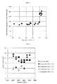
- FIG. 1 a relationship between a tool abrasion amount (machinability) and addition amounts of Mo, W and V of the invention steels and the Comparative steels are shown.
- FIG. 2 a relationship between an impact value and a numerical value of hardness of the invention steels and the Comparative steels are shown.
- Comparative steel 14 With reference to Table 1, Table 2 and Table 3, since the contents of Mo and V were below the lower limit of the limited range of the present invention and the content of Cr exceeded the upper limit of the limited range of the present invention, the Comparative steel 14 could not achieve a sufficient hardness. In addition, since the content of C exceeded the upper limit of the limited range of the present invention, the Comparative steel 14 had a low impact value.
- Comparative steel 16 in Table 3 is an example in which a test was performed in a condition of a composition identical to that of Comparative steel 14 in Table 2, and a tempering temperature and a quenching temperature different from that of Comparative steel 14 in Table 3.
- the Invention steels achieved excellent results in any test result of the hardness measurement test, the Charpy impact test, the machinability test, and the measurement test of the amount of retaining austenite, compared to these Comparative steels. From the results described above, according to the steel for cold working tool of the present embodiment, it is possible to improve productivity of the die while ensuring necessary hardness and a necessary impact value of the die.
Abstract
Description
- The present invention relates to a steel for cold working tool, and in particular, relates to a steel for cold working tool, which is preferable for forming a high tensile steel plate.
- In general, steel for cold working tool, represented by SKD11 is usually used at approximately HRC 60 to HRC 63 after being subjected to a quenching treatment at a temperature higher than or equal to 1,000°C and then being subjected to a tempering treatment at a temperature higher than or equal to 450°C. As a principal use of this steel for cold working tool, a die for cold pressing and a die for cold forging are exemplified. For example,
Patent Document 1 discloses a steel for cold working tool which achieves high hardness and high toughness by improving the size and the distribution of carbide. - On the other hand, recently, in the automobile industry, a countermeasure to global warming issues has been required, and as the most effective solution, many companies have focused on a reduction in weight of vehicle body. It is known that when the reduction in vehicle body weight is advanced, an amount of carbon dioxide discharged from the vehicle is able to be reduced. For this reason, a material which can provide strength identical to that of a common steel plate usually adopted as a material of a vehicle body even when used in a thinner thickness than the common one, is used as an automobile body or a structural component. Such a material is called a high tensile steel plate.
- The high tensile steel plate is also called "High Tensile Strength Steel Sheets", and indicates a steel plate having a high tensile strength. The common steel plate has tensile strength greater than or equal to 270 MPa, whereas a steel plate having tensile strength of 340 MPa to 790 MPa is generally defined as the high tensile steel plate. In addition, a steel plate having tensile strength greater than or equal to 1,000 MPa is particularly called a super high tensile steel plate.
- Patent Document 1:
JP-A-H02-277745 - From a demand for a reduction in weight of vehicle body of an automobile, steel for cold working tool (a cold working die) has been increasingly applied for the processing of the super high tensile steel plate. For this reason, when the super high tensile steel plate is formed by using a cold working die, a load for the cold working die has been increased. If the cold working die cannot be resistant to the load, the cold working die is deformed and thus dimensional accuracy of the automobile body or the structural component is degraded. In order to obtain sufficient load resistance, it is necessary to ensure hardness and an impact value of the cold working die. In order to obtain high hardness while considering resource saving, it is effective that a larger amount of carbon is dissolved into a material steel to form a solid solution in a quenching treatment, and then secondary hardening is performed by a tempering treatment.
- As a method for increasing the dissolved amount of carbon in the solid solution, a method of increasing a quenching temperature is exemplified. However, when the quenching temperature is increased, there may be a problem in that crystal grains in steel are coarsened. The coarsened crystal grains lead to the decrease in the impact value of the die steel. Therefore, it is necessary to contain a carbide such as VC which prevents the coarsening of the crystal grain at the quenching temperature, but when an amount of the carbide which prevents the coarsening of the crystal grain excessively increases, the impact value also decreases. In addition, when an element such as Mo and V is added, an improvement in hardness due to the secondary hardening is expected.
- On the other hand, when focused on a manufacturing process of the cold working die, the cold working die is usually machined at room temperature and is finished into a final shape. This machining process is a repetition of a rupture due to shear deformation of a die material (steel for cold working tool) and abrasion of ruptured swarf and the tool, and a temperature on a machined surface of the die material temporarily and instantaneously increases. If the die is difficult to be deformed at this high temperature, that is, if hardness at a high temperature increases, machinability decreases. That is, a load for the tool machining the die increases (a tool abrasion amount increases), and thus the cost of a machine tool and the time for manufacturing the die increase, and productivity of the die decreases.
- The present invention was made in consideration of the circumstances described above, and is to solve the above-described problem by providing a steel for cold working tool, which can improve productivity of a die while ensuring necessary hardness and a necessary impact value of the die.
- As a result of intensive studies, the present inventors found that the above-described problem can be solved. Specific means for solving the problem are as follows.
- A first aspect of the present invention is a steel for cold working tool, which contains, on a % by mass basis:
- C: 0.70% to 0.90%;
- Si: 0.60% to 0.80%;
- Mn: 0.30% to 0.50%;
- P: 0.30% or less;
- S: 0.030% or less;
- Cu: 0.01% to 0.25%;
- Ni: 0.01% to 0.25%;
- Cr: 6.0% to 7.0%;
- Mo + 1/2W: 2.50% to 3.00%;
- V: 0.70% to 0.85%;
- N: 0.020% or less;
- O:0.0100% or less; and
- Al: 0.100% or less,
- A second aspect of the present invention is the steel for cold working tool according to the first aspect, which further contains, on a % by mass basis, at least one of the following:
- Nb: 0.001% to 0.30%,
- Ta: 0.001% to 0.30%,
- Ti: 0.20% or less, and
- Zr: 0.001% to 0.30%.
- A third aspect of the present invention is the steel for cold working tool according to the first or the second aspect, which has an amount of retaining austenite after quenching being less than or equal to 25 vol%.
- A fourth aspect of the present invention is the steel for cold working tool according to any one of the first, the second and the third aspects, which has a highest hardness after a tempering treatment at a temperature higher than or equal to 450°C being greater than or equal to 64 HRC.
- The present invention ensures the hardness and impact value necessary for a die by adjusting C, Si, Cr, Mo, W, and V to be in a predetermined range. In addition, in the present invention, a balance among Mo, W, and V is optimized, and a relational expression of 1.66 (Mo + 1/2W) + V < 5.7% is specified in order to improve productivity of the die. Usually, the die is machined at room temperature, and the temperature of the die is temporarily and instantaneously increased by machining heat during the machining. In this case, when focused on hardness of the die, the hardness is highest at room temperature and decreases as the temperature rises. As a result of intensive studies of the present inventors, it is found that in the case where the temperature of the die is temporarily and instantaneously increased by the machining, in particular, if a larger amount of each element of Mo, W, and V than a predetermined addition amount has been added, machinability is impaired and thus machining efficiency is degraded. That is, they concluded that the element addition amount of Mo, W, and V is one factor of decreasing productivity of the die.
- Incidentally, the steel for cold working tool disclosed in
Patent Document 1 described above realizes high hardness and high toughness by improving the size and the distribution of carbide, but does not have the characteristics of the present invention and thus has completely different technical concepts. - As described above, according to the steel for cold working tool of the present invention, it is possible to improve productivity of a die while ensuring the hardness and impact value necessary for the die.
-
-
FIG. 1 is a diagram showing a relationship between a tool abrasion amount (machinability) and an addition amount of Mo, W and V. -
FIG. 2 is a diagram showing a relationship between an impact value and a numerical value of hardness of the invention steels and the Comparative steels. - The steel for cold working tool according to one embodiment of the present invention (hereinafter, referred to as the steel for cold working tool of this embodiment) will be described in detail. The steel for cold working tool of this embodiment is able to be applied to a forming die for a high tensile steel plate, a punch and die for cold forging, a bending die, a die for cold forging, a die for swaging, a die for thread rolling, a punch member, a slitter knife, a die for punching a lead frame, a gauge, a deep drawing punch, a bending punch, a shear blade, a bending die for stainless steel, a drawing die, a tool for plastic working such as heading, a punch for a gear, a cam component, a die for press punching, a die for progressive punching, a seal plate for a sediment transport device, a screw member, a rotary plate for a concrete spraying machine, a die for sealing an IC, and a precision press die requiring high dimensional accuracy. In addition, the steel for cold working tool of this embodiment is also able to be used for various cold metal dice used after performing a surface treatment such as a CVD treatment, a PVD treatment, and a TD treatment. Among them, it is particularly preferable to be used for a super high tensile steel plate having tensile strength greater than or equal to 1,000 MPa.
- The steel for cold working tool of this embodiment contains the following elements. A kind of added element, an added range thereof, and a reason for limiting the range thereof are explained as follows.
- C is a necessary element for ensuring strength and abrasion resistance, and forms a carbide by being bonded to a carbide forming element such as Cr, Mo, W, V, and Nb. In addition, C is also necessary for ensuring hardness by being dissolved into a matrix phase to form a solid solution at the time of quenching to thereby form a martensite structure. In order to obtain such an effect in the steel for cold working tool, a lower limit of the content of C is set to be 0.70%. In contrast, when the content of C is excessively large, the carbide forming element and C are bonded to form a coarse carbide and thus an impact value may decrease. In addition, hot workability at the time of performing hot forging with respect to an ingot after casting may decrease. For these reasons, an upper limit of the content of C is set to be 0.90%. From the viewpoints described above, a more preferred range of the content of C is 0.75% to 0.85%.
- Si is dissolved into a matrix phase to form a solid solution, can accelerate precipitation of other carbides, and can contribute to secondary hardening. In order to obtain these effects, a lower limit of the content of Si is set to be 0.60%. In contrast, when Si is excessively added, quenching properties may decrease. For this reason, an upper limit of the content of Si is set to be 0.80%.
- Mn is added for improving quenching properties and stabilizing austenite. In particular, when the quenching properties decrease, a variation in hardness increases at a micro-level. In addition, Mn forms MnS when S is inevitably contained, and can prevent a decrease in an impact value caused by a distortion (facilitation of anisotropy) due to a heat treatment. For these reasons, a lower limit of the content of Mn is set to be 0.30%. In contrast, when the content of Mn is excessively large, hot workability at the time of performing hot forging with respect to an ingot after casting may decrease. For this reason, an upper limit of the content of Mn is set to be 0.50%.
- P is inevitably contained in steel. P is easily segregated on a crystal grain boundary and may cause a decrease in toughness. For this reason, an upper limit of the content of P is set to be 0.3%.
- S is inevitably contained in steel. Usually, S is positively added in order to improve machinability. In the present invention, MnS can be formed by adding S to prevent a decrease in an impact value caused by a distortion (facilitation of anisotropy) due to a heat treatment, and thus the content of S is limited to be less than or equal to 0.03%.
- Cu is an element stabilizing austenite. However, when the content of Cu is excessively large, an amount of retaining austenite may increase and thus a change in dimension over time may occur. In addition, when Cu is excessively added, hot workability at the time of performing hot forging with respect to an ingot after casting may decrease. For these reasons, the content of Cu is set to be 0.01% to 0.25%.
- Ni is an element stabilizing austenite. However, when the content of Ni is excessively large, an amount of retaining austenite may increase and thus a change in dimension over time may occur. For this reason, the content of Ni is set to be 0.01% to 0.25%.
- Cr is an element improving corrosion resistance. In order to obtain this effect, a lower limit of the content of Cr is set to be 6.0%. When the content of Cr is excessively large, the amount of C dissolved into an austenite structure to form a solid solution may decrease, and thus sufficient hardness may not be obtained. For this reason, an upper limit of the content of Cr is set to be 7.0%.
- Mo and W form fine carbides, and are important elements contributing to secondary hardening. In order to obtain the same effect as that of Mo, it is necessary to add a double amount W, and thus in the present invention, a total amount of a content of Mo and 1/2 of a content of W is limited. In order to obtain the effect of the secondary hardening, a lower limit of the content of Mo + 1/2W is set to be 2.50%. In contrast, when the contents of Mo and W are excessively large, an amount of carbides retaining at the time of quenching may increase, and thus an upper limit of the content of Mo + 1/2W is set to be 3.00%.
- V can be bonded to C to form a carbide. The carbide can contribute to suppression of coarsening in a crystal grain diameter. In order to obtain this effect, a lower limit of the content of V is set to be 0.70%. When the content of V is excessively large, a carbonitride of V may easily be crystallized to decrease an impact value. For this reason, an upper limit of the content of V is set to be 0.85%.
- N is an interstitial type element and can contribute to an increase in hardness of a martensite structure. N has a stronger y stabilizing ability compared to carbon which is the same interstitial type element. However, when the content of N is excessively large, nitrogen in a steel material may concentrate during solidification to exceed a limit of nitrogen gas ejection, and thus voids easily occur in an ingot. For this reason, an upper limit of the content of N is set to be 0.020%.
- O is an element which is inevitably contained in molten steel. However, when the content of O is excessively large, O may be bonded to Si and Al to form coarse oxides which become an inclusion, and thus toughness may decrease. From a viewpoint of preventing this, an upper limit of the content of O is set to be 0.0100%.
- Al is an element which is added as a deoxidizing agent. However, when the content of Al is excessively large, Al may be bonded to O to form a coarse oxide and it may become a starting point of a crack. For this reason, an upper limit of the content of Al is set to be 0.100%.
- In order to increase secondary hardening, it is necessary to add Mo + 1/2W and V. In contrast, when a total content thereof is excessively large, even if the temperature of a die is increased by machining resistance or a machining heat at the time of machining, hardness of the die may not decrease, and thus machinability may be degraded. For this reason, the total content thereof is specified so as to satisfy 1.66 (Mo + 1/2W) + V < 5.7.
- The steel for cold working tool of this embodiment may optionally contain one or more kinds of elements selected from the elements described below in addition to the above-described essential elements. That is, the steel for cold working tool of this embodiment may consist only of, on a % by mass basis: 0.70 ≤ C ≤ 0.90; 0.60 ≤ Si ≤ 0.80; 0.30 ≤ Mn ≤ 0.50; P ≤ 0.30; S ≤ 0.030; 0.01 ≤ Cu ≤ 0.25; 0.01 ≤ Ni ≤ 0.25; 6.0 ≤ Cr ≤ 7.0; 2.50 ≤ Mo + 1/2W ≤ 3.00; 0.70 ≤ V ≤ 0.85; N ≤ 0.020; 0 ≤ 0.0100; and A1 ≤ 0.100, with the balance being Fe and inevitable impurities in which 1.66 (Mo + 1/2W) + V < 5.7% is satisfied, but it may optionally contain one or more kinds of elements selected from the elements with its contents as described below.
- Nb, Ta, Ti, and Zr are elements which are bonded to C and N to form carbonitrides, and may contribute to suppression of coarsening in a crystal grain. In contrast, when Nb, Ta, Ti, and Zr are excessively added, machinability at the time of finishing may decrease, and thus productivity of a die may decrease. For these reason, a content of each element is set to be in the range described above.
- In addition, in the steel for cold working tool of this embodiment, it is preferable that an amount of retaining austenite after quenching is less than or equal to 25 vol%. This is because when the amount of retaining austenite after quenching increases, a change in dimension of a die due to an amount of retaining austenite to be decomposed after tempering may increase, and thus it may take time to perform precision machining with respect to the die. Furthermore, it is preferable that the quenching temperature is 1,000°C to 1,100°C.
- In addition, in the steel for cold working tool of this embodiment, it is preferable that the highest hardness after a tempering treatment at a temperature greater than or equal to 450°C is greater than or equal to 64 HRC. In particular, when the steel for cold working tool of this embodiment is used as a cold working die for a high tensile steel plate, it is necessary to ensure hardness and an impact value by applying secondary hardening.
- Hereinafter, the present invention will be described in detail with reference to examples.
- Steels each having chemical composition (mass%) shown in Tables 1 and 2 were melted in a vacuum induction furnace, and casted into respective ingots having 50 kg of weight. These ingots after the casting were subjected to hot forging and formed into respective rod materials of 60 mm square. After the hot forging, these rod materials were subjected to spheroidizing annealing in which the materials were slowly cooled at a cooling speed of 7°C/hr from 880°C. Each obtained steel material was evaluated for a hardness measurement test, a Charpy impact test, a machinability test, and a measurement test of an amount of retaining austenite.
- A cubic test piece of which a side was 10 mm was cut out from the rod material after the heat treatment described above and was treated in heat treatment conditions shown in Table 3 (a quenching temperature and a tempering temperature). A measuring surface and a grounding surface of the cubic test piece were ground up to #400. And then, hardness of the cubic test piece was measured by using a Rockwell C Scale. The hardness indicates the highest hardness in the case where a tempering treatment has been conducted at a temperature higher than or equal to 450°C.
- A 10R-notch Charpy test piece in which a notch of 2 mm having a depth of 10R was formed in a square rod material of 10 mm x 10 mm x 55 mm cut out from the rod material of 60 mm square described above was prepared. The 10R-notch Charpy test piece was subjected to a quenching treatment and a tempering treatment at a temperature shown in Table 3, and then an impact value thereof was measured at room temperature. The impact value was obtained as an average value of three test pieces.
- The machinability test was performed with respect to the following test piece which was cut out from a steel material after annealing. Test conditions are as follows.
Test Piece: 55 mm x 55 mm x 200 mm
Machining Tool: a square end mill of super hard M20 (φ 10 mm)
Machining Distance: 10m
Machining Speed: 100 m/min
Transport Speed per Revolution: 0.2 mm/rev
Cutout Width (Horizontal Direction): 0.5 mm
Cutout Height (Vertical Direction): 0.5 mm
Machine Oil: none - In the evaluation, the end mill was detached from a holder after machining of 10 m, and the maximum abrasion amount of a corner portion of the square end mill was measured. The maximum abrasion amount of the corner portion of the square end mill was measured by real measurement using a CCD camera of 3 magnifications. Here, the "maximum abrasion amount of the corner portion of the square end mill" indicates a maximum value of a distance from a tip of the corner portion of the square end mill to a position where peeling and abrasion are able to be confirmed.
- A square rod material of 10 mm x 10 mm x 2 mm which was cut out from the rod material of 60 mm square was maintained at the quenching temperature shown in Table 3 for 30 minutes, and then was cooled at an average cooling speed of 50°C/min. Next, a measuring surface of the square rod material (test piece) was ground up to #800 defined by JIS-R6001 (1998), and was measured by an X-ray diffraction device. A peak intensity of (200) and (211) of ferrite and a peak intensity of (200), (220) and (311) of austenite were obtained by X-ray measurement, and then an amount of retaining austenite (vol%) was calculated from a peak intensity ratio.
- In Tables 1 and 2, chemical compositions of the invention steels and steels of Comparative Examples are shown. In Table 3, heat treatment conditions and test results of the invention steels and the Comparative steels are shown. In addition, in
FIG. 1 , a relationship between a tool abrasion amount (machinability) and addition amounts of Mo, W and V of the invention steels and the Comparative steels are shown. InFIG. 2 , a relationship between an impact value and a numerical value of hardness of the invention steels and the Comparative steels are shown.[Table 1] Steel Type C Si Mn P S Cu Ni Cr Mo W Mo +1/2W V N O Al Others 1.66 (Mo + 1/2W) + V Invention Steel 1 0.82 0.68 0.37 0.11 0.012 0.09 0.11 6.67 2.62 - 2.62 0.82 0.012 0.0052 0.064 - 5.17 Invention Steel 2 0.72 0.60 0.36 0.16 0.021 0.13 0.09 6.48 2.91 - 2.91 0.75 0.007 0.0096 0.052 Nb = 0.038 5.58 Invention Steel 3 0.78 0.71 0.48 0.19 0.022 0.04 0.05 6.23 2.73 - 2.73 0.79 0.014 0.0021 0.074 - 5.32 Invention Steel 4 0.85 0.63 0.42 0.02 0.014 0.21 0.17 6.56 2.65 - 2.65 0.77 0.018 0.0063 0.088 - 5.17 Invention Steel 5 0.88 0.74 0.30 0.04 0.016 0.07 0.15 6.92 2.83 - 2.83 0.73 0.020 0.0081 0.091 Ta = 0.012 5.43 Invention Steel 6 0.76 0.65 0.44 0.08 0.018 0.05 0.07 6.07 2.96 - 2.96 0.74 0.019 0.0014 0.068 - 5.65 Invention Steel 7 0.86 0.76 0.32 0.26 0.007 0.16 0.14 6.84 2.76 - 2.76 0.84 0.004 0.0073 0.043 - 5.42 Invention Steel 8 0.71 0.64 0.33 0.23 0.005 0.02 0.21 6.51 2.52 - 2.52 0.76 0.003 0.0007 0.032 Ti = 0.05 4.94 Invention Steel 9 0.75 0.78 0.39 0.12 0.025 0.24 0.24 6.16 2.85 - 2.85 0.71 0.015 0.0046 0.021 - 5.44 Invention Steel 10 0.81 0.79 0.46 0.28 0.027 0.18 0.02 6.35 0.08 5.83 3.00 0.85 0.017 0.0032 0.011 Zr = 0.03 5.65 [Table 2] Steel Type C Si Mn P S Cu Ni Cr Mo W Mo +1/2W V N O Al Others 1.66 (Mo + 1/2W) + V Comp. Steel 10.83 0.62 0.48 0.22 0.004 0.25 0.12 6.54 2.96 - 2.96 0.83 0.003 0.0033 0.036 - 5.74 Comp. Steel 2 0.73 0.70 0.35 0.13 0.018 0.07 0.19 6.34 2.95 - 2.95 0.84 0.019 0.0084 0.085 - 5.74 Comp. Steel 3 0.86 0.75 0.38 0.15 0.026 0.03 0.23 6.28 2.98 - 2.98 0.82 0.011 0.0068 0.062 - 5.77 Comp. Steel 4 0.80 0.73 0.32 0.29 0.011 0.11 0.03 6.46 2.94 - 2.94 0.85 0.014 0.0006 0.013 - 5.73 Comp. Steel 5 0.90 0.61 0.46 0.03 0.021 0.21 0.15 6.54 2.97 - 2.97 0.83 0.013 0.0098 0.055 - 5.76 Comp. Steel 6 0.75 0.66 0.36 0.04 0.030 0.16 0.25 6.25 0.15 5.82 3.06 0.84 0.002 0.0028 0.024 - 5.75 Comp. Steel 7 0.89 0.79 0.30 0.12 0.034 0.01 0.07 6.52 2.68 - 2.68 0.94 0.008 0.0057 0.073 - 5.39 Comp. Steel 8 0.81 0.74 0.42 0.09 0.038 0.24 0.21 6.31 2.93 - 2.93 0.83 0.005 0.0013 0.096 - 5.69 Comp. Steel 9 0.71 0.64 0.34 0.17 0.026 0.04 0.13 6.38 2.54 - 2.54 0.88 0.017 0.0076 0.031 - 5.10 Comp. Steel 100.84 0.76 0.49 0.26 0.036 0.18 0.17 6.41 2.73 - 2.73 0.82 0.015 0.0048 0.048 - 5.35 Comp. Steel 11 0.77 0.80 0.37 0.14 0.032 0.08 0.15 6.35 2.81 - 2.81 0.89 0.009 0.0065 0.067 - 5.55 Comp. Steel 12 0.88 0.67 0.44 0.08 0.028 0.12 0.18 6.76 0.10 5.73 2.965 0.95 0.008 0.0062 0.056 - 5.70 Comp. Steel 13 1.52 0.26 0.43 0.13 0.016 0.06 0.13 12.06 1.09 - 1.09 0.24 0.017 0.0086 0.022 - 2.05 Comp. Steel 14 1.04 1.02 0.41 0.11 0.004 0.07 0.11 8.09 2.11 - 2.11 0.23 0.016 0.0054 0.046 - 3.73 Comp. Steel 150.65 1.99 0.91 0.08 0.072 0.08 0.08 6.66 1.46 - 1.46 0.11 0.006 0.0032 0.072 - 2.53 [Table 3] Steel Type Quenching Temperature (°C) Tempering Temperature (°C) Highest Hardness (HRC) Impact Value (J/cm2) Tool Abrasion Amount (µm) Retaining γ Amount (Vol%) Invention Steel 11085 535 64.4 17 126 22.7 Invention Steel 2 1090 550 64.3 21 131 19.8 Invention Steel 3 1085 540 64.7 23 121 21.6 Invention Steel 4 1100 530 64.5 16 128 23.7 Invention Steel 5 1080 545 64.8 23 127 24.5 Invention Steel 6 1095 535 64.2 24 123 21.0 Invention Steel 7 1075 540 64.7 21 135 23.9 Invention Steel 8 1070 555 64.5 18 124 19.4 Invention Steel 9 1080 525 64.3 19 129 20.6 Invention Steel 101075 560 64.2 22 138 24.3 Comp. Steel 11075 545 64.6 16 212 23.1 Comp. Steel 2 1085 550 64.8 18 232 20.1 Comp. Steel 3 1080 540 64.4 21 225 24.9 Comp. Steel 4 1090 555 64.6 18 234 24.1 Comp. Steel 5 1085 560 64.5 16 254 25.3 Comp. Steel 6 1100 545 64.7 18 235 20.7 Comp. Steel 7 1070 550 64.2 9 119 24.8 Comp. Steel 8 1080 540 64.3 11 142 22.5 Comp. Steel 9 1075 535 64.5 12 114 19.4 Comp. Steel 101085 545 64.6 10 116 23.5 Comp. Steel 11 1090 530 64.4 8 118 21.3 Comp. Steel 12 1080 525 64.2 11 223 24.6 Comp. Steel 13 1020 500 60.2 7 121 41.3 Comp. Steel 14 1030 520 62.9 9 114 21.2 Comp. Steel 151030 500 62.1 20 88 21.1 Comp. Steel 16 1080 540 63.6 6 109 29.6 - Comparing Table 1, Table 2, Table 3,
FIG. 1, and FIG. 2 , the following facts can be found. First, in Comparative steels 1 to 6, 1.66 (Mo + 1/2W) + V was greater than or equal to 5.7. For this reason, the tool abrasion amount increases, and productivity of the die decreases. Specifically, with reference toFIG. 1 , a plot in which 1.66 (Mo + 1/2W) is greater than or equal to 5.7 indicatesComparative steels 1 to 6. In contrast, a plot in which 1.66 (Mo + 1/2W) is less than 5.7 indicates the invention steels 1 to 9 and Comparative steels 7 to 12. As shown inFIG. 1 , when 1.66 (Mo + 1/2W) is greater than or equal to 5.7 in an alloy composition, the tool abrasion amount increases, machinability decreases, and productivity of the die decreases. - With reference to Table 1, Table 2, Table 3, and
FIG. 2 , since either one or both of S and V exceeded the upper limit of the limited range of the present invention, the Comparative steels 8 to 12 had a low impact value. - With reference to Table 1, Table 2, Table 3, and
FIG. 2 , since the contents of Si, Mo, and V were below the lower limit of the limited range of the present invention and the content of Cr exceeded the upper limit of the limited range of the present invention, the Comparative steel 13 could not achieve a sufficient hardness. In addition, since the content of C exceeded the upper limit of the limited range of the present invention, the Comparative steel 13 had a low impact value. - With reference to Table 1, Table 2 and Table 3, since the contents of Mo and V were below the lower limit of the limited range of the present invention and the content of Cr exceeded the upper limit of the limited range of the present invention, the Comparative steel 14 could not achieve a sufficient hardness. In addition, since the content of C exceeded the upper limit of the limited range of the present invention, the Comparative steel 14 had a low impact value. Incidentally, Comparative steel 16 in Table 3 is an example in which a test was performed in a condition of a composition identical to that of Comparative steel 14 in Table 2, and a tempering temperature and a quenching temperature different from that of Comparative steel 14 in Table 3.
- With reference to Table 1, Table 2 and Table 3, since the contents of C, Mo and V were below the lower limit of the limited range of the present invention and the content of Cr exceeded the upper limit of the limited range of the present invention, the
Comparative steel 15 could not achieve a sufficient hardness. - In contrast, the Invention steels achieved excellent results in any test result of the hardness measurement test, the Charpy impact test, the machinability test, and the measurement test of the amount of retaining austenite, compared to these Comparative steels. From the results described above, according to the steel for cold working tool of the present embodiment, it is possible to improve productivity of the die while ensuring necessary hardness and a necessary impact value of the die.
- While the present invention has been described in detail and with reference to specific embodiments thereof, it will be apparent that various changes and modifications can be made therein without limited to these embodiments and examples.
- The present application is based on a Japanese patent application
2014-125901 filed on June 19, 2014 2014-218985 filed on October 28, 2014 2014-243681 filed on December 2, 2014
in which 1.66 (Mo + 1/2W) + V < 5.7% is satisfied.
Claims (8)
- A steel for cold working tool, comprising, on a % by mass basis:C: 0.70% to 0.90%;Si: 0.60% to 0.80%;Mn: 0.30% to 0.50%;P: 0.30% or less;S: 0.030% or less;Cu: 0.01% to 0.25%;Ni: 0.01% to 0.25%;Cr: 6.0% to 7.0%;Mo + 1/2W: 2.50% to 3.00%;V: 0.70% to 0.85%;N: 0.020% or less;O: 0.0100% or less; andAl: 0.100% or less,with the balance being Fe and inevitable impurities,wherein 1.66 (Mo + 1/2W) + V < 5.7% is satisfied.
- The steel for cold working tool according to claim 1, further comprising, on a % by mass basis, at least one of the following:Nb: 0.001% to 0.30%,Ta: 0.001% to 0.30%,Ti: 0.20% or less, andZr: 0.001% to 0.30%.
- The steel for cold working tool according to claim 1 or 2, having an amount of retaining austenite after quenching being less than or equal to 25 vol%.
- The steel for cold working tool according to any one of claims 1 to 3, having a highest hardness after a tempering treatment at a temperature higher than or equal to 450°C being greater than or equal to 64 HRC.
- The steel for cold working tool according to one of claims 1 to 4, further comprising, on a % by mass basis, at least one of the following:Nb: up to 0.30%,Ta: up to 0.30%, andZr: up to 0.30%.
- Use of the steel of one of claims 1 to 5, for a die for cold pressing or a die for cold forging.
- The use according to claim 6, wherein the die is used for cold pressing or cold forging a High Tensile Strength Steel Sheet.
- The use according to claim 7, wherein the tensile strength of the steel plate is at least 340 MPa.
Applications Claiming Priority (3)
| Application Number | Priority Date | Filing Date | Title |
|---|---|---|---|
| JP2014125901 | 2014-06-19 | ||
| JP2014218985 | 2014-10-28 | ||
| JP2014243681A JP6439227B2 (en) | 2014-06-19 | 2014-12-02 | Cold work tool steel |
Publications (3)
| Publication Number | Publication Date |
|---|---|
| EP2957647A2 true EP2957647A2 (en) | 2015-12-23 |
| EP2957647A3 EP2957647A3 (en) | 2016-01-13 |
| EP2957647B1 EP2957647B1 (en) | 2017-02-15 |
Family
ID=53396345
Family Applications (1)
| Application Number | Title | Priority Date | Filing Date |
|---|---|---|---|
| EP15171821.0A Active EP2957647B1 (en) | 2014-06-19 | 2015-06-12 | Steel for cold working tool |
Country Status (3)
| Country | Link |
|---|---|
| EP (1) | EP2957647B1 (en) |
| CN (1) | CN105274444B (en) |
| TW (1) | TWI647318B (en) |
Cited By (1)
| Publication number | Priority date | Publication date | Assignee | Title |
|---|---|---|---|---|
| CN112011740A (en) * | 2020-08-31 | 2020-12-01 | 天津钢研海德科技有限公司 | High-toughness and high-hardness die steel and preparation method thereof |
Citations (1)
| Publication number | Priority date | Publication date | Assignee | Title |
|---|---|---|---|---|
| JPH02277745A (en) | 1989-01-20 | 1990-11-14 | Hitachi Metals Ltd | High hardness and high toughness cold tool steel |
Family Cites Families (6)
| Publication number | Priority date | Publication date | Assignee | Title |
|---|---|---|---|---|
| JPH03134136A (en) * | 1989-10-18 | 1991-06-07 | Hitachi Metals Ltd | High hardness and high toughness cold tool steel |
| JP2765392B2 (en) * | 1992-08-31 | 1998-06-11 | 住友金属工業株式会社 | Method for manufacturing hot-rolled duplex stainless steel strip |
| JP3134136B2 (en) | 1992-12-25 | 2001-02-13 | 中西金属工業株式会社 | Moving object position detection device |
| JP4239300B2 (en) * | 1999-06-14 | 2009-03-18 | 大同特殊鋼株式会社 | Cold mold steel |
| JP4403875B2 (en) * | 2004-05-14 | 2010-01-27 | 大同特殊鋼株式会社 | Cold work tool steel |
| JP5338188B2 (en) * | 2007-10-31 | 2013-11-13 | 大同特殊鋼株式会社 | Alloy tool steel and manufacturing method thereof |
-
2015
- 2015-05-18 CN CN201510252702.3A patent/CN105274444B/en active Active
- 2015-05-28 TW TW104117149A patent/TWI647318B/en active
- 2015-06-12 EP EP15171821.0A patent/EP2957647B1/en active Active
Patent Citations (1)
| Publication number | Priority date | Publication date | Assignee | Title |
|---|---|---|---|---|
| JPH02277745A (en) | 1989-01-20 | 1990-11-14 | Hitachi Metals Ltd | High hardness and high toughness cold tool steel |
Cited By (1)
| Publication number | Priority date | Publication date | Assignee | Title |
|---|---|---|---|---|
| CN112011740A (en) * | 2020-08-31 | 2020-12-01 | 天津钢研海德科技有限公司 | High-toughness and high-hardness die steel and preparation method thereof |
Also Published As
| Publication number | Publication date |
|---|---|
| TW201604291A (en) | 2016-02-01 |
| EP2957647A3 (en) | 2016-01-13 |
| EP2957647B1 (en) | 2017-02-15 |
| TWI647318B (en) | 2019-01-11 |
| CN105274444B (en) | 2019-03-19 |
| CN105274444A (en) | 2016-01-27 |
Similar Documents
| Publication | Publication Date | Title |
|---|---|---|
| EP3214194B1 (en) | Austenitic stainless steel and manufacturing method therefor | |
| KR101779305B1 (en) | Austenitic stainless steel sheet and method for producing same | |
| EP2520682B1 (en) | Steel material for quenching and method of producing same | |
| EP2792761B1 (en) | High-strength extra-thick steel h-beam | |
| EP2617852A1 (en) | High-strength hot-rolled steel sheet having excellent bending workability and method for producing same | |
| EP3085803A1 (en) | H-shaped steel and method for producing same | |
| EP2784169B1 (en) | Rolled steel bar for hot forging | |
| CN107709594B (en) | Bolt | |
| EP3438308A1 (en) | Ti-containing ferritic stainless steel sheet, manufacturing method, and flange | |
| EP2990500B1 (en) | Steel sheet | |
| EP3460085A1 (en) | Ti-containing ferrite stainless steel sheet for exhaust pipe flange component, production method and flange component | |
| EP3093358A1 (en) | Steel material and process for producing same | |
| EP3093362A1 (en) | Ferritic stainless steel and method for producing same | |
| JP2005226150A (en) | Annealing method of tool steel, production method of annealed material for tool steel, annealed material for tool steel, tool steel using the same and tool | |
| JP2009533554A (en) | Cold work steel | |
| EP2957647B1 (en) | Steel for cold working tool | |
| EP2803745B1 (en) | Hot-rolled steel sheet and manufacturing method for same | |
| JP2007314837A (en) | Age hardening type ferritic stainless steel sheet and age-treated steel material using the same | |
| KR20180117129A (en) | Rolled wire rod | |
| JP2018131654A (en) | Hot work tool steel having excellent toughness and softening resistance | |
| KR102311270B1 (en) | Steel for cold working tool | |
| EP3255165B1 (en) | Cold work tool material, cold work tool and method for manufacturing same | |
| JP3497387B2 (en) | Molds and tools made of high hardness cold tool steel | |
| JP2016156081A (en) | Alloy tool steel | |
| SE542781C2 (en) | A method of producing a high speed steel alloy |
Legal Events
| Date | Code | Title | Description |
|---|---|---|---|
| PUAL | Search report despatched |
Free format text: ORIGINAL CODE: 0009013 |
|
| PUAI | Public reference made under article 153(3) epc to a published international application that has entered the european phase |
Free format text: ORIGINAL CODE: 0009012 |
|
| AK | Designated contracting states |
Kind code of ref document: A2 Designated state(s): AL AT BE BG CH CY CZ DE DK EE ES FI FR GB GR HR HU IE IS IT LI LT LU LV MC MK MT NL NO PL PT RO RS SE SI SK SM TR |
|
| AX | Request for extension of the european patent |
Extension state: BA ME |
|
| AK | Designated contracting states |
Kind code of ref document: A3 Designated state(s): AL AT BE BG CH CY CZ DE DK EE ES FI FR GB GR HR HU IE IS IT LI LT LU LV MC MK MT NL NO PL PT RO RS SE SI SK SM TR |
|
| AX | Request for extension of the european patent |
Extension state: BA ME |
|
| RIC1 | Information provided on ipc code assigned before grant |
Ipc: C22C 38/04 20060101ALI20151209BHEP Ipc: C22C 38/48 20060101ALI20151209BHEP Ipc: C22C 38/46 20060101ALI20151209BHEP Ipc: C22C 38/02 20060101ALI20151209BHEP Ipc: C22C 38/44 20060101ALI20151209BHEP Ipc: C22C 38/06 20060101ALI20151209BHEP Ipc: C22C 38/42 20060101ALI20151209BHEP Ipc: C22C 38/50 20060101ALI20151209BHEP Ipc: C21D 6/02 20060101ALI20151209BHEP Ipc: C22C 38/00 20060101AFI20151209BHEP Ipc: C21D 6/00 20060101ALI20151209BHEP Ipc: C21D 1/18 20060101ALI20151209BHEP |
|
| 17P | Request for examination filed |
Effective date: 20160706 |
|
| RBV | Designated contracting states (corrected) |
Designated state(s): AL AT BE BG CH CY CZ DE DK EE ES FI FR GB GR HR HU IE IS IT LI LT LU LV MC MK MT NL NO PL PT RO RS SE SI SK SM TR |
|
| GRAP | Despatch of communication of intention to grant a patent |
Free format text: ORIGINAL CODE: EPIDOSNIGR1 |
|
| INTG | Intention to grant announced |
Effective date: 20160921 |
|
| GRAS | Grant fee paid |
Free format text: ORIGINAL CODE: EPIDOSNIGR3 |
|
| GRAA | (expected) grant |
Free format text: ORIGINAL CODE: 0009210 |
|
| AK | Designated contracting states |
Kind code of ref document: B1 Designated state(s): AL AT BE BG CH CY CZ DE DK EE ES FI FR GB GR HR HU IE IS IT LI LT LU LV MC MK MT NL NO PL PT RO RS SE SI SK SM TR |
|
| REG | Reference to a national code |
Ref country code: CH Ref legal event code: EP Ref country code: GB Ref legal event code: FG4D |
|
| REG | Reference to a national code |
Ref country code: IE Ref legal event code: FG4D |
|
| REG | Reference to a national code |
Ref country code: AT Ref legal event code: REF Ref document number: 867936 Country of ref document: AT Kind code of ref document: T Effective date: 20170315 |
|
| REG | Reference to a national code |
Ref country code: DE Ref legal event code: R096 Ref document number: 602015001494 Country of ref document: DE |
|
| REG | Reference to a national code |
Ref country code: SE Ref legal event code: TRGR |
|
| REG | Reference to a national code |
Ref country code: NL Ref legal event code: MP Effective date: 20170215 |
|
| REG | Reference to a national code |
Ref country code: LT Ref legal event code: MG4D |
|
| PG25 | Lapsed in a contracting state [announced via postgrant information from national office to epo] |
Ref country code: HR Free format text: LAPSE BECAUSE OF FAILURE TO SUBMIT A TRANSLATION OF THE DESCRIPTION OR TO PAY THE FEE WITHIN THE PRESCRIBED TIME-LIMIT Effective date: 20170215 Ref country code: LT Free format text: LAPSE BECAUSE OF FAILURE TO SUBMIT A TRANSLATION OF THE DESCRIPTION OR TO PAY THE FEE WITHIN THE PRESCRIBED TIME-LIMIT Effective date: 20170215 Ref country code: NO Free format text: LAPSE BECAUSE OF FAILURE TO SUBMIT A TRANSLATION OF THE DESCRIPTION OR TO PAY THE FEE WITHIN THE PRESCRIBED TIME-LIMIT Effective date: 20170515 Ref country code: GR Free format text: LAPSE BECAUSE OF FAILURE TO SUBMIT A TRANSLATION OF THE DESCRIPTION OR TO PAY THE FEE WITHIN THE PRESCRIBED TIME-LIMIT Effective date: 20170516 Ref country code: FI Free format text: LAPSE BECAUSE OF FAILURE TO SUBMIT A TRANSLATION OF THE DESCRIPTION OR TO PAY THE FEE WITHIN THE PRESCRIBED TIME-LIMIT Effective date: 20170215 |
|
| PG25 | Lapsed in a contracting state [announced via postgrant information from national office to epo] |
Ref country code: BG Free format text: LAPSE BECAUSE OF FAILURE TO SUBMIT A TRANSLATION OF THE DESCRIPTION OR TO PAY THE FEE WITHIN THE PRESCRIBED TIME-LIMIT Effective date: 20170515 Ref country code: RS Free format text: LAPSE BECAUSE OF FAILURE TO SUBMIT A TRANSLATION OF THE DESCRIPTION OR TO PAY THE FEE WITHIN THE PRESCRIBED TIME-LIMIT Effective date: 20170215 Ref country code: PT Free format text: LAPSE BECAUSE OF FAILURE TO SUBMIT A TRANSLATION OF THE DESCRIPTION OR TO PAY THE FEE WITHIN THE PRESCRIBED TIME-LIMIT Effective date: 20170615 Ref country code: NL Free format text: LAPSE BECAUSE OF NON-PAYMENT OF DUE FEES Effective date: 20170215 Ref country code: LV Free format text: LAPSE BECAUSE OF FAILURE TO SUBMIT A TRANSLATION OF THE DESCRIPTION OR TO PAY THE FEE WITHIN THE PRESCRIBED TIME-LIMIT Effective date: 20170215 Ref country code: ES Free format text: LAPSE BECAUSE OF FAILURE TO SUBMIT A TRANSLATION OF THE DESCRIPTION OR TO PAY THE FEE WITHIN THE PRESCRIBED TIME-LIMIT Effective date: 20170215 |
|
| PG25 | Lapsed in a contracting state [announced via postgrant information from national office to epo] |
Ref country code: CZ Free format text: LAPSE BECAUSE OF FAILURE TO SUBMIT A TRANSLATION OF THE DESCRIPTION OR TO PAY THE FEE WITHIN THE PRESCRIBED TIME-LIMIT Effective date: 20170215 Ref country code: SK Free format text: LAPSE BECAUSE OF FAILURE TO SUBMIT A TRANSLATION OF THE DESCRIPTION OR TO PAY THE FEE WITHIN THE PRESCRIBED TIME-LIMIT Effective date: 20170215 Ref country code: IT Free format text: LAPSE BECAUSE OF FAILURE TO SUBMIT A TRANSLATION OF THE DESCRIPTION OR TO PAY THE FEE WITHIN THE PRESCRIBED TIME-LIMIT Effective date: 20170215 Ref country code: RO Free format text: LAPSE BECAUSE OF FAILURE TO SUBMIT A TRANSLATION OF THE DESCRIPTION OR TO PAY THE FEE WITHIN THE PRESCRIBED TIME-LIMIT Effective date: 20170215 Ref country code: EE Free format text: LAPSE BECAUSE OF FAILURE TO SUBMIT A TRANSLATION OF THE DESCRIPTION OR TO PAY THE FEE WITHIN THE PRESCRIBED TIME-LIMIT Effective date: 20170215 |
|
| REG | Reference to a national code |
Ref country code: DE Ref legal event code: R097 Ref document number: 602015001494 Country of ref document: DE |
|
| PG25 | Lapsed in a contracting state [announced via postgrant information from national office to epo] |
Ref country code: SM Free format text: LAPSE BECAUSE OF FAILURE TO SUBMIT A TRANSLATION OF THE DESCRIPTION OR TO PAY THE FEE WITHIN THE PRESCRIBED TIME-LIMIT Effective date: 20170215 Ref country code: DK Free format text: LAPSE BECAUSE OF FAILURE TO SUBMIT A TRANSLATION OF THE DESCRIPTION OR TO PAY THE FEE WITHIN THE PRESCRIBED TIME-LIMIT Effective date: 20170215 Ref country code: PL Free format text: LAPSE BECAUSE OF FAILURE TO SUBMIT A TRANSLATION OF THE DESCRIPTION OR TO PAY THE FEE WITHIN THE PRESCRIBED TIME-LIMIT Effective date: 20170215 |
|
| PLBE | No opposition filed within time limit |
Free format text: ORIGINAL CODE: 0009261 |
|
| STAA | Information on the status of an ep patent application or granted ep patent |
Free format text: STATUS: NO OPPOSITION FILED WITHIN TIME LIMIT |
|
| 26N | No opposition filed |
Effective date: 20171116 |
|
| PG25 | Lapsed in a contracting state [announced via postgrant information from national office to epo] |
Ref country code: MC Free format text: LAPSE BECAUSE OF FAILURE TO SUBMIT A TRANSLATION OF THE DESCRIPTION OR TO PAY THE FEE WITHIN THE PRESCRIBED TIME-LIMIT Effective date: 20170215 |
|
| PG25 | Lapsed in a contracting state [announced via postgrant information from national office to epo] |
Ref country code: SI Free format text: LAPSE BECAUSE OF FAILURE TO SUBMIT A TRANSLATION OF THE DESCRIPTION OR TO PAY THE FEE WITHIN THE PRESCRIBED TIME-LIMIT Effective date: 20170215 |
|
| REG | Reference to a national code |
Ref country code: IE Ref legal event code: MM4A |
|
| REG | Reference to a national code |
Ref country code: FR Ref legal event code: ST Effective date: 20180228 |
|
| PG25 | Lapsed in a contracting state [announced via postgrant information from national office to epo] |
Ref country code: IE Free format text: LAPSE BECAUSE OF NON-PAYMENT OF DUE FEES Effective date: 20170612 Ref country code: LU Free format text: LAPSE BECAUSE OF NON-PAYMENT OF DUE FEES Effective date: 20170612 |
|
| REG | Reference to a national code |
Ref country code: BE Ref legal event code: MM Effective date: 20170630 |
|
| PG25 | Lapsed in a contracting state [announced via postgrant information from national office to epo] |
Ref country code: FR Free format text: LAPSE BECAUSE OF NON-PAYMENT OF DUE FEES Effective date: 20170630 |
|
| PG25 | Lapsed in a contracting state [announced via postgrant information from national office to epo] |
Ref country code: BE Free format text: LAPSE BECAUSE OF NON-PAYMENT OF DUE FEES Effective date: 20170630 |
|
| PG25 | Lapsed in a contracting state [announced via postgrant information from national office to epo] |
Ref country code: MT Free format text: LAPSE BECAUSE OF NON-PAYMENT OF DUE FEES Effective date: 20170612 |
|
| REG | Reference to a national code |
Ref country code: CH Ref legal event code: PL |
|
| PG25 | Lapsed in a contracting state [announced via postgrant information from national office to epo] |
Ref country code: CH Free format text: LAPSE BECAUSE OF NON-PAYMENT OF DUE FEES Effective date: 20180630 Ref country code: LI Free format text: LAPSE BECAUSE OF NON-PAYMENT OF DUE FEES Effective date: 20180630 |
|
| PG25 | Lapsed in a contracting state [announced via postgrant information from national office to epo] |
Ref country code: HU Free format text: LAPSE BECAUSE OF FAILURE TO SUBMIT A TRANSLATION OF THE DESCRIPTION OR TO PAY THE FEE WITHIN THE PRESCRIBED TIME-LIMIT; INVALID AB INITIO Effective date: 20150612 |
|
| PG25 | Lapsed in a contracting state [announced via postgrant information from national office to epo] |
Ref country code: CY Free format text: LAPSE BECAUSE OF FAILURE TO SUBMIT A TRANSLATION OF THE DESCRIPTION OR TO PAY THE FEE WITHIN THE PRESCRIBED TIME-LIMIT Effective date: 20170215 |
|
| PG25 | Lapsed in a contracting state [announced via postgrant information from national office to epo] |
Ref country code: MK Free format text: LAPSE BECAUSE OF FAILURE TO SUBMIT A TRANSLATION OF THE DESCRIPTION OR TO PAY THE FEE WITHIN THE PRESCRIBED TIME-LIMIT Effective date: 20170215 |
|
| GBPC | Gb: european patent ceased through non-payment of renewal fee |
Effective date: 20190612 |
|
| REG | Reference to a national code |
Ref country code: AT Ref legal event code: UEP Ref document number: 867936 Country of ref document: AT Kind code of ref document: T Effective date: 20170215 |
|
| PG25 | Lapsed in a contracting state [announced via postgrant information from national office to epo] |
Ref country code: TR Free format text: LAPSE BECAUSE OF FAILURE TO SUBMIT A TRANSLATION OF THE DESCRIPTION OR TO PAY THE FEE WITHIN THE PRESCRIBED TIME-LIMIT Effective date: 20170215 |
|
| PG25 | Lapsed in a contracting state [announced via postgrant information from national office to epo] |
Ref country code: GB Free format text: LAPSE BECAUSE OF NON-PAYMENT OF DUE FEES Effective date: 20190612 |
|
| PG25 | Lapsed in a contracting state [announced via postgrant information from national office to epo] |
Ref country code: AL Free format text: LAPSE BECAUSE OF FAILURE TO SUBMIT A TRANSLATION OF THE DESCRIPTION OR TO PAY THE FEE WITHIN THE PRESCRIBED TIME-LIMIT Effective date: 20170215 Ref country code: IS Free format text: LAPSE BECAUSE OF FAILURE TO SUBMIT A TRANSLATION OF THE DESCRIPTION OR TO PAY THE FEE WITHIN THE PRESCRIBED TIME-LIMIT Effective date: 20170615 |
|
| PGFP | Annual fee paid to national office [announced via postgrant information from national office to epo] |
Ref country code: DE Payment date: 20230502 Year of fee payment: 9 |
|
| PGFP | Annual fee paid to national office [announced via postgrant information from national office to epo] |
Ref country code: SE Payment date: 20230510 Year of fee payment: 9 Ref country code: AT Payment date: 20230525 Year of fee payment: 9 |