EP2957445A1 - Hybrid powertrain unit for motor vehicles with engagement devices on opposite sides of the electric machine - Google Patents
Hybrid powertrain unit for motor vehicles with engagement devices on opposite sides of the electric machine Download PDFInfo
- Publication number
- EP2957445A1 EP2957445A1 EP14172693.5A EP14172693A EP2957445A1 EP 2957445 A1 EP2957445 A1 EP 2957445A1 EP 14172693 A EP14172693 A EP 14172693A EP 2957445 A1 EP2957445 A1 EP 2957445A1
- Authority
- EP
- European Patent Office
- Prior art keywords
- shaft
- electric machine
- differential
- pulley
- engagement device
- Prior art date
- Legal status (The legal status is an assumption and is not a legal conclusion. Google has not performed a legal analysis and makes no representation as to the accuracy of the status listed.)
- Granted
Links
Images







Classifications
-
- B—PERFORMING OPERATIONS; TRANSPORTING
- B60—VEHICLES IN GENERAL
- B60K—ARRANGEMENT OR MOUNTING OF PROPULSION UNITS OR OF TRANSMISSIONS IN VEHICLES; ARRANGEMENT OR MOUNTING OF PLURAL DIVERSE PRIME-MOVERS IN VEHICLES; AUXILIARY DRIVES FOR VEHICLES; INSTRUMENTATION OR DASHBOARDS FOR VEHICLES; ARRANGEMENTS IN CONNECTION WITH COOLING, AIR INTAKE, GAS EXHAUST OR FUEL SUPPLY OF PROPULSION UNITS IN VEHICLES
- B60K6/00—Arrangement or mounting of plural diverse prime-movers for mutual or common propulsion, e.g. hybrid propulsion systems comprising electric motors and internal combustion engines
- B60K6/20—Arrangement or mounting of plural diverse prime-movers for mutual or common propulsion, e.g. hybrid propulsion systems comprising electric motors and internal combustion engines the prime-movers consisting of electric motors and internal combustion engines, e.g. HEVs
- B60K6/42—Arrangement or mounting of plural diverse prime-movers for mutual or common propulsion, e.g. hybrid propulsion systems comprising electric motors and internal combustion engines the prime-movers consisting of electric motors and internal combustion engines, e.g. HEVs characterised by the architecture of the hybrid electric vehicle
- B60K6/44—Series-parallel type
- B60K6/445—Differential gearing distribution type
-
- B—PERFORMING OPERATIONS; TRANSPORTING
- B60—VEHICLES IN GENERAL
- B60K—ARRANGEMENT OR MOUNTING OF PROPULSION UNITS OR OF TRANSMISSIONS IN VEHICLES; ARRANGEMENT OR MOUNTING OF PLURAL DIVERSE PRIME-MOVERS IN VEHICLES; AUXILIARY DRIVES FOR VEHICLES; INSTRUMENTATION OR DASHBOARDS FOR VEHICLES; ARRANGEMENTS IN CONNECTION WITH COOLING, AIR INTAKE, GAS EXHAUST OR FUEL SUPPLY OF PROPULSION UNITS IN VEHICLES
- B60K6/00—Arrangement or mounting of plural diverse prime-movers for mutual or common propulsion, e.g. hybrid propulsion systems comprising electric motors and internal combustion engines
- B60K6/20—Arrangement or mounting of plural diverse prime-movers for mutual or common propulsion, e.g. hybrid propulsion systems comprising electric motors and internal combustion engines the prime-movers consisting of electric motors and internal combustion engines, e.g. HEVs
- B60K6/22—Arrangement or mounting of plural diverse prime-movers for mutual or common propulsion, e.g. hybrid propulsion systems comprising electric motors and internal combustion engines the prime-movers consisting of electric motors and internal combustion engines, e.g. HEVs characterised by apparatus, components or means specially adapted for HEVs
- B60K6/38—Arrangement or mounting of plural diverse prime-movers for mutual or common propulsion, e.g. hybrid propulsion systems comprising electric motors and internal combustion engines the prime-movers consisting of electric motors and internal combustion engines, e.g. HEVs characterised by apparatus, components or means specially adapted for HEVs characterised by the driveline clutches
- B60K6/387—Actuated clutches, i.e. clutches engaged or disengaged by electric, hydraulic or mechanical actuating means
-
- B—PERFORMING OPERATIONS; TRANSPORTING
- B60—VEHICLES IN GENERAL
- B60K—ARRANGEMENT OR MOUNTING OF PROPULSION UNITS OR OF TRANSMISSIONS IN VEHICLES; ARRANGEMENT OR MOUNTING OF PLURAL DIVERSE PRIME-MOVERS IN VEHICLES; AUXILIARY DRIVES FOR VEHICLES; INSTRUMENTATION OR DASHBOARDS FOR VEHICLES; ARRANGEMENTS IN CONNECTION WITH COOLING, AIR INTAKE, GAS EXHAUST OR FUEL SUPPLY OF PROPULSION UNITS IN VEHICLES
- B60K6/00—Arrangement or mounting of plural diverse prime-movers for mutual or common propulsion, e.g. hybrid propulsion systems comprising electric motors and internal combustion engines
- B60K6/20—Arrangement or mounting of plural diverse prime-movers for mutual or common propulsion, e.g. hybrid propulsion systems comprising electric motors and internal combustion engines the prime-movers consisting of electric motors and internal combustion engines, e.g. HEVs
- B60K6/22—Arrangement or mounting of plural diverse prime-movers for mutual or common propulsion, e.g. hybrid propulsion systems comprising electric motors and internal combustion engines the prime-movers consisting of electric motors and internal combustion engines, e.g. HEVs characterised by apparatus, components or means specially adapted for HEVs
- B60K6/26—Arrangement or mounting of plural diverse prime-movers for mutual or common propulsion, e.g. hybrid propulsion systems comprising electric motors and internal combustion engines the prime-movers consisting of electric motors and internal combustion engines, e.g. HEVs characterised by apparatus, components or means specially adapted for HEVs characterised by the motors or the generators
-
- B—PERFORMING OPERATIONS; TRANSPORTING
- B60—VEHICLES IN GENERAL
- B60K—ARRANGEMENT OR MOUNTING OF PROPULSION UNITS OR OF TRANSMISSIONS IN VEHICLES; ARRANGEMENT OR MOUNTING OF PLURAL DIVERSE PRIME-MOVERS IN VEHICLES; AUXILIARY DRIVES FOR VEHICLES; INSTRUMENTATION OR DASHBOARDS FOR VEHICLES; ARRANGEMENTS IN CONNECTION WITH COOLING, AIR INTAKE, GAS EXHAUST OR FUEL SUPPLY OF PROPULSION UNITS IN VEHICLES
- B60K6/00—Arrangement or mounting of plural diverse prime-movers for mutual or common propulsion, e.g. hybrid propulsion systems comprising electric motors and internal combustion engines
- B60K6/20—Arrangement or mounting of plural diverse prime-movers for mutual or common propulsion, e.g. hybrid propulsion systems comprising electric motors and internal combustion engines the prime-movers consisting of electric motors and internal combustion engines, e.g. HEVs
- B60K6/22—Arrangement or mounting of plural diverse prime-movers for mutual or common propulsion, e.g. hybrid propulsion systems comprising electric motors and internal combustion engines the prime-movers consisting of electric motors and internal combustion engines, e.g. HEVs characterised by apparatus, components or means specially adapted for HEVs
- B60K6/36—Arrangement or mounting of plural diverse prime-movers for mutual or common propulsion, e.g. hybrid propulsion systems comprising electric motors and internal combustion engines the prime-movers consisting of electric motors and internal combustion engines, e.g. HEVs characterised by apparatus, components or means specially adapted for HEVs characterised by the transmission gearings
- B60K6/365—Arrangement or mounting of plural diverse prime-movers for mutual or common propulsion, e.g. hybrid propulsion systems comprising electric motors and internal combustion engines the prime-movers consisting of electric motors and internal combustion engines, e.g. HEVs characterised by apparatus, components or means specially adapted for HEVs characterised by the transmission gearings with the gears having orbital motion
-
- B—PERFORMING OPERATIONS; TRANSPORTING
- B60—VEHICLES IN GENERAL
- B60K—ARRANGEMENT OR MOUNTING OF PROPULSION UNITS OR OF TRANSMISSIONS IN VEHICLES; ARRANGEMENT OR MOUNTING OF PLURAL DIVERSE PRIME-MOVERS IN VEHICLES; AUXILIARY DRIVES FOR VEHICLES; INSTRUMENTATION OR DASHBOARDS FOR VEHICLES; ARRANGEMENTS IN CONNECTION WITH COOLING, AIR INTAKE, GAS EXHAUST OR FUEL SUPPLY OF PROPULSION UNITS IN VEHICLES
- B60K6/00—Arrangement or mounting of plural diverse prime-movers for mutual or common propulsion, e.g. hybrid propulsion systems comprising electric motors and internal combustion engines
- B60K6/20—Arrangement or mounting of plural diverse prime-movers for mutual or common propulsion, e.g. hybrid propulsion systems comprising electric motors and internal combustion engines the prime-movers consisting of electric motors and internal combustion engines, e.g. HEVs
- B60K6/22—Arrangement or mounting of plural diverse prime-movers for mutual or common propulsion, e.g. hybrid propulsion systems comprising electric motors and internal combustion engines the prime-movers consisting of electric motors and internal combustion engines, e.g. HEVs characterised by apparatus, components or means specially adapted for HEVs
- B60K6/40—Arrangement or mounting of plural diverse prime-movers for mutual or common propulsion, e.g. hybrid propulsion systems comprising electric motors and internal combustion engines the prime-movers consisting of electric motors and internal combustion engines, e.g. HEVs characterised by apparatus, components or means specially adapted for HEVs characterised by the assembly or relative disposition of components
-
- B—PERFORMING OPERATIONS; TRANSPORTING
- B60—VEHICLES IN GENERAL
- B60K—ARRANGEMENT OR MOUNTING OF PROPULSION UNITS OR OF TRANSMISSIONS IN VEHICLES; ARRANGEMENT OR MOUNTING OF PLURAL DIVERSE PRIME-MOVERS IN VEHICLES; AUXILIARY DRIVES FOR VEHICLES; INSTRUMENTATION OR DASHBOARDS FOR VEHICLES; ARRANGEMENTS IN CONNECTION WITH COOLING, AIR INTAKE, GAS EXHAUST OR FUEL SUPPLY OF PROPULSION UNITS IN VEHICLES
- B60K6/00—Arrangement or mounting of plural diverse prime-movers for mutual or common propulsion, e.g. hybrid propulsion systems comprising electric motors and internal combustion engines
- B60K6/20—Arrangement or mounting of plural diverse prime-movers for mutual or common propulsion, e.g. hybrid propulsion systems comprising electric motors and internal combustion engines the prime-movers consisting of electric motors and internal combustion engines, e.g. HEVs
- B60K6/42—Arrangement or mounting of plural diverse prime-movers for mutual or common propulsion, e.g. hybrid propulsion systems comprising electric motors and internal combustion engines the prime-movers consisting of electric motors and internal combustion engines, e.g. HEVs characterised by the architecture of the hybrid electric vehicle
- B60K6/48—Parallel type
-
- B—PERFORMING OPERATIONS; TRANSPORTING
- B60—VEHICLES IN GENERAL
- B60K—ARRANGEMENT OR MOUNTING OF PROPULSION UNITS OR OF TRANSMISSIONS IN VEHICLES; ARRANGEMENT OR MOUNTING OF PLURAL DIVERSE PRIME-MOVERS IN VEHICLES; AUXILIARY DRIVES FOR VEHICLES; INSTRUMENTATION OR DASHBOARDS FOR VEHICLES; ARRANGEMENTS IN CONNECTION WITH COOLING, AIR INTAKE, GAS EXHAUST OR FUEL SUPPLY OF PROPULSION UNITS IN VEHICLES
- B60K6/00—Arrangement or mounting of plural diverse prime-movers for mutual or common propulsion, e.g. hybrid propulsion systems comprising electric motors and internal combustion engines
- B60K6/20—Arrangement or mounting of plural diverse prime-movers for mutual or common propulsion, e.g. hybrid propulsion systems comprising electric motors and internal combustion engines the prime-movers consisting of electric motors and internal combustion engines, e.g. HEVs
- B60K6/50—Architecture of the driveline characterised by arrangement or kind of transmission units
- B60K6/54—Transmission for changing ratio
- B60K6/547—Transmission for changing ratio the transmission being a stepped gearing
-
- B—PERFORMING OPERATIONS; TRANSPORTING
- B60—VEHICLES IN GENERAL
- B60K—ARRANGEMENT OR MOUNTING OF PROPULSION UNITS OR OF TRANSMISSIONS IN VEHICLES; ARRANGEMENT OR MOUNTING OF PLURAL DIVERSE PRIME-MOVERS IN VEHICLES; AUXILIARY DRIVES FOR VEHICLES; INSTRUMENTATION OR DASHBOARDS FOR VEHICLES; ARRANGEMENTS IN CONNECTION WITH COOLING, AIR INTAKE, GAS EXHAUST OR FUEL SUPPLY OF PROPULSION UNITS IN VEHICLES
- B60K6/00—Arrangement or mounting of plural diverse prime-movers for mutual or common propulsion, e.g. hybrid propulsion systems comprising electric motors and internal combustion engines
- B60K6/20—Arrangement or mounting of plural diverse prime-movers for mutual or common propulsion, e.g. hybrid propulsion systems comprising electric motors and internal combustion engines the prime-movers consisting of electric motors and internal combustion engines, e.g. HEVs
- B60K6/22—Arrangement or mounting of plural diverse prime-movers for mutual or common propulsion, e.g. hybrid propulsion systems comprising electric motors and internal combustion engines the prime-movers consisting of electric motors and internal combustion engines, e.g. HEVs characterised by apparatus, components or means specially adapted for HEVs
- B60K6/38—Arrangement or mounting of plural diverse prime-movers for mutual or common propulsion, e.g. hybrid propulsion systems comprising electric motors and internal combustion engines the prime-movers consisting of electric motors and internal combustion engines, e.g. HEVs characterised by apparatus, components or means specially adapted for HEVs characterised by the driveline clutches
- B60K2006/381—Arrangement or mounting of plural diverse prime-movers for mutual or common propulsion, e.g. hybrid propulsion systems comprising electric motors and internal combustion engines the prime-movers consisting of electric motors and internal combustion engines, e.g. HEVs characterised by apparatus, components or means specially adapted for HEVs characterised by the driveline clutches characterized by driveline brakes
-
- B—PERFORMING OPERATIONS; TRANSPORTING
- B60—VEHICLES IN GENERAL
- B60K—ARRANGEMENT OR MOUNTING OF PROPULSION UNITS OR OF TRANSMISSIONS IN VEHICLES; ARRANGEMENT OR MOUNTING OF PLURAL DIVERSE PRIME-MOVERS IN VEHICLES; AUXILIARY DRIVES FOR VEHICLES; INSTRUMENTATION OR DASHBOARDS FOR VEHICLES; ARRANGEMENTS IN CONNECTION WITH COOLING, AIR INTAKE, GAS EXHAUST OR FUEL SUPPLY OF PROPULSION UNITS IN VEHICLES
- B60K6/00—Arrangement or mounting of plural diverse prime-movers for mutual or common propulsion, e.g. hybrid propulsion systems comprising electric motors and internal combustion engines
- B60K6/20—Arrangement or mounting of plural diverse prime-movers for mutual or common propulsion, e.g. hybrid propulsion systems comprising electric motors and internal combustion engines the prime-movers consisting of electric motors and internal combustion engines, e.g. HEVs
- B60K6/42—Arrangement or mounting of plural diverse prime-movers for mutual or common propulsion, e.g. hybrid propulsion systems comprising electric motors and internal combustion engines the prime-movers consisting of electric motors and internal combustion engines, e.g. HEVs characterised by the architecture of the hybrid electric vehicle
- B60K6/48—Parallel type
- B60K2006/4833—Step up or reduction gearing driving generator, e.g. to operate generator in most efficient speed range
- B60K2006/4841—Step up or reduction gearing driving generator, e.g. to operate generator in most efficient speed range the gear provides shifting between multiple ratios
-
- B—PERFORMING OPERATIONS; TRANSPORTING
- B60—VEHICLES IN GENERAL
- B60K—ARRANGEMENT OR MOUNTING OF PROPULSION UNITS OR OF TRANSMISSIONS IN VEHICLES; ARRANGEMENT OR MOUNTING OF PLURAL DIVERSE PRIME-MOVERS IN VEHICLES; AUXILIARY DRIVES FOR VEHICLES; INSTRUMENTATION OR DASHBOARDS FOR VEHICLES; ARRANGEMENTS IN CONNECTION WITH COOLING, AIR INTAKE, GAS EXHAUST OR FUEL SUPPLY OF PROPULSION UNITS IN VEHICLES
- B60K25/00—Auxiliary drives
- B60K2025/005—Auxiliary drives driven by electric motors forming part of the propulsion unit
-
- B—PERFORMING OPERATIONS; TRANSPORTING
- B60—VEHICLES IN GENERAL
- B60K—ARRANGEMENT OR MOUNTING OF PROPULSION UNITS OR OF TRANSMISSIONS IN VEHICLES; ARRANGEMENT OR MOUNTING OF PLURAL DIVERSE PRIME-MOVERS IN VEHICLES; AUXILIARY DRIVES FOR VEHICLES; INSTRUMENTATION OR DASHBOARDS FOR VEHICLES; ARRANGEMENTS IN CONNECTION WITH COOLING, AIR INTAKE, GAS EXHAUST OR FUEL SUPPLY OF PROPULSION UNITS IN VEHICLES
- B60K25/00—Auxiliary drives
- B60K25/02—Auxiliary drives directly from an engine shaft
- B60K2025/022—Auxiliary drives directly from an engine shaft by a mechanical transmission
-
- B—PERFORMING OPERATIONS; TRANSPORTING
- B60—VEHICLES IN GENERAL
- B60K—ARRANGEMENT OR MOUNTING OF PROPULSION UNITS OR OF TRANSMISSIONS IN VEHICLES; ARRANGEMENT OR MOUNTING OF PLURAL DIVERSE PRIME-MOVERS IN VEHICLES; AUXILIARY DRIVES FOR VEHICLES; INSTRUMENTATION OR DASHBOARDS FOR VEHICLES; ARRANGEMENTS IN CONNECTION WITH COOLING, AIR INTAKE, GAS EXHAUST OR FUEL SUPPLY OF PROPULSION UNITS IN VEHICLES
- B60K6/00—Arrangement or mounting of plural diverse prime-movers for mutual or common propulsion, e.g. hybrid propulsion systems comprising electric motors and internal combustion engines
- B60K6/20—Arrangement or mounting of plural diverse prime-movers for mutual or common propulsion, e.g. hybrid propulsion systems comprising electric motors and internal combustion engines the prime-movers consisting of electric motors and internal combustion engines, e.g. HEVs
- B60K6/50—Architecture of the driveline characterised by arrangement or kind of transmission units
- B60K6/52—Driving a plurality of drive axles, e.g. four-wheel drive
-
- F—MECHANICAL ENGINEERING; LIGHTING; HEATING; WEAPONS; BLASTING
- F16—ENGINEERING ELEMENTS AND UNITS; GENERAL MEASURES FOR PRODUCING AND MAINTAINING EFFECTIVE FUNCTIONING OF MACHINES OR INSTALLATIONS; THERMAL INSULATION IN GENERAL
- F16H—GEARING
- F16H37/00—Combinations of mechanical gearings, not provided for in groups F16H1/00 - F16H35/00
- F16H37/02—Combinations of mechanical gearings, not provided for in groups F16H1/00 - F16H35/00 comprising essentially only toothed or friction gearings
- F16H37/06—Combinations of mechanical gearings, not provided for in groups F16H1/00 - F16H35/00 comprising essentially only toothed or friction gearings with a plurality of driving or driven shafts; with arrangements for dividing torque between two or more intermediate shafts
- F16H37/08—Combinations of mechanical gearings, not provided for in groups F16H1/00 - F16H35/00 comprising essentially only toothed or friction gearings with a plurality of driving or driven shafts; with arrangements for dividing torque between two or more intermediate shafts with differential gearing
- F16H37/10—Combinations of mechanical gearings, not provided for in groups F16H1/00 - F16H35/00 comprising essentially only toothed or friction gearings with a plurality of driving or driven shafts; with arrangements for dividing torque between two or more intermediate shafts with differential gearing at both ends of intermediate shafts
- F16H2037/101—Power-split transmissions with one differential at each end of a continuously variable transmission, i.e. CVT
-
- Y—GENERAL TAGGING OF NEW TECHNOLOGICAL DEVELOPMENTS; GENERAL TAGGING OF CROSS-SECTIONAL TECHNOLOGIES SPANNING OVER SEVERAL SECTIONS OF THE IPC; TECHNICAL SUBJECTS COVERED BY FORMER USPC CROSS-REFERENCE ART COLLECTIONS [XRACs] AND DIGESTS
- Y02—TECHNOLOGIES OR APPLICATIONS FOR MITIGATION OR ADAPTATION AGAINST CLIMATE CHANGE
- Y02T—CLIMATE CHANGE MITIGATION TECHNOLOGIES RELATED TO TRANSPORTATION
- Y02T10/00—Road transport of goods or passengers
- Y02T10/60—Other road transportation technologies with climate change mitigation effect
- Y02T10/62—Hybrid vehicles
-
- Y—GENERAL TAGGING OF NEW TECHNOLOGICAL DEVELOPMENTS; GENERAL TAGGING OF CROSS-SECTIONAL TECHNOLOGIES SPANNING OVER SEVERAL SECTIONS OF THE IPC; TECHNICAL SUBJECTS COVERED BY FORMER USPC CROSS-REFERENCE ART COLLECTIONS [XRACs] AND DIGESTS
- Y10—TECHNICAL SUBJECTS COVERED BY FORMER USPC
- Y10S—TECHNICAL SUBJECTS COVERED BY FORMER USPC CROSS-REFERENCE ART COLLECTIONS [XRACs] AND DIGESTS
- Y10S903/00—Hybrid electric vehicles, HEVS
- Y10S903/902—Prime movers comprising electrical and internal combustion motors
- Y10S903/903—Prime movers comprising electrical and internal combustion motors having energy storing means, e.g. battery, capacitor
- Y10S903/904—Component specially adapted for hev
- Y10S903/906—Motor or generator
-
- Y—GENERAL TAGGING OF NEW TECHNOLOGICAL DEVELOPMENTS; GENERAL TAGGING OF CROSS-SECTIONAL TECHNOLOGIES SPANNING OVER SEVERAL SECTIONS OF THE IPC; TECHNICAL SUBJECTS COVERED BY FORMER USPC CROSS-REFERENCE ART COLLECTIONS [XRACs] AND DIGESTS
- Y10—TECHNICAL SUBJECTS COVERED BY FORMER USPC
- Y10S—TECHNICAL SUBJECTS COVERED BY FORMER USPC CROSS-REFERENCE ART COLLECTIONS [XRACs] AND DIGESTS
- Y10S903/00—Hybrid electric vehicles, HEVS
- Y10S903/902—Prime movers comprising electrical and internal combustion motors
- Y10S903/903—Prime movers comprising electrical and internal combustion motors having energy storing means, e.g. battery, capacitor
- Y10S903/904—Component specially adapted for hev
- Y10S903/909—Gearing
- Y10S903/91—Orbital, e.g. planetary gears
-
- Y—GENERAL TAGGING OF NEW TECHNOLOGICAL DEVELOPMENTS; GENERAL TAGGING OF CROSS-SECTIONAL TECHNOLOGIES SPANNING OVER SEVERAL SECTIONS OF THE IPC; TECHNICAL SUBJECTS COVERED BY FORMER USPC CROSS-REFERENCE ART COLLECTIONS [XRACs] AND DIGESTS
- Y10—TECHNICAL SUBJECTS COVERED BY FORMER USPC
- Y10S—TECHNICAL SUBJECTS COVERED BY FORMER USPC CROSS-REFERENCE ART COLLECTIONS [XRACs] AND DIGESTS
- Y10S903/00—Hybrid electric vehicles, HEVS
- Y10S903/902—Prime movers comprising electrical and internal combustion motors
- Y10S903/903—Prime movers comprising electrical and internal combustion motors having energy storing means, e.g. battery, capacitor
- Y10S903/904—Component specially adapted for hev
- Y10S903/912—Drive line clutch
- Y10S903/914—Actuated, e.g. engaged or disengaged by electrical, hydraulic or mechanical means
-
- Y—GENERAL TAGGING OF NEW TECHNOLOGICAL DEVELOPMENTS; GENERAL TAGGING OF CROSS-SECTIONAL TECHNOLOGIES SPANNING OVER SEVERAL SECTIONS OF THE IPC; TECHNICAL SUBJECTS COVERED BY FORMER USPC CROSS-REFERENCE ART COLLECTIONS [XRACs] AND DIGESTS
- Y10—TECHNICAL SUBJECTS COVERED BY FORMER USPC
- Y10S—TECHNICAL SUBJECTS COVERED BY FORMER USPC CROSS-REFERENCE ART COLLECTIONS [XRACs] AND DIGESTS
- Y10S903/00—Hybrid electric vehicles, HEVS
- Y10S903/902—Prime movers comprising electrical and internal combustion motors
- Y10S903/903—Prime movers comprising electrical and internal combustion motors having energy storing means, e.g. battery, capacitor
- Y10S903/904—Component specially adapted for hev
- Y10S903/915—Specific drive or transmission adapted for hev
- Y10S903/917—Specific drive or transmission adapted for hev with transmission for changing gear ratio
- Y10S903/919—Stepped shift
Definitions
- the present invention relates to a hybrid powertrain unit for motor vehicles, of the type comprising:
- a hybrid powertrain unit of the type referred to above is known, for example, from EP 1 868 832 B1 .
- DE 10 2009 0566366 A1 and US 2002/065163 A1 also disclose a hybrid powertrain unit of the type referred to above, which also comprises an engagement device arranged, in the connecting transmission, between the shaft of the electric machine and the aforesaid second crown wheel of the differential, and means for actuating the aforesaid engagement device.
- This document illustrates also a second engagement device arranged between the second pulley and the shaft of the internal-combustion engine.
- this document mentions also the possibility of providing the second engagement device in a position arranged between said first pulley and the shaft of the electric machine.
- the object of the present invention is to provide a hybrid powertrain unit that will have a simple structure and small overall dimensions and that will be efficient, reliable, and versatile in operation.
- the subject of the invention is a hybrid powertrain unit of the type specified above, with the engagement device arranged between the shaft of the electric machine and the second crown wheel of the differential, the unit being further characterized in that:
- Direct connection between the shaft of the internal-combustion engine and the shaft of the electric machine makes it possible to provide, for example, a function of the electric machine as BAS (Belt Alternator Starter), i.e., as generator driven by the engine or as electric motor for starting the internal-combustion engine.
- BAS Belt Alternator Starter
- first engagement device and second engagement device are clutch engagement devices provided with actuator means comprising an electromagnetic or electrohydraulic actuator and an electronic unit for controlling the actuators.
- Activation of the engagement devices is controlled independently by the electronic control unit of the motor vehicle according to a pre-arranged program, as a function of the operating parameters of the engine and of the motor vehicle.
- the above transmission that connects the shaft of the electric machine to the aforesaid second crown wheel of the differential includes a gear for driving a transmission shaft connected to a further axle of the vehicle.
- Provision in the unit according to the invention of a gear for driving a transmission shaft connected to a further axle of the vehicle enables efficient application to vehicles with four-wheel drive.
- the aforesaid gear for driving the transmission shaft connected to the further axle of the vehicle may be arranged, for example, between the second crown wheel of the differential and the engagement device, or else alternatively between the engagement device and the shaft of the electric machine.
- the torque of the electric machine is shared between the front axle and the rear axle in a way identical to what occurs for the torque of the internal-combustion engine, whereas in the latter case the functions of the electric machine are irrespective of the distribution of the torque of the internal-combustion engine and may even envisage that 100% of the torque of the internal-combustion engine is transmitted to the front axle of the motor vehicle and 100% of the torque of the electric machine is transmitted to the rear axle.
- the above transmission that connects the shaft of the electric machine to said second crown wheel of the differential includes at least one gear-reduction jump constituted by a belt transmission.
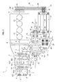
- number 1 designates as a whole a hybrid powertrain unit for motor vehicles, comprising an internal-combustion engine E, a gearbox device C, a differential D, and an electric machine M.
- the gearbox device C has a casing 2, rotatably mounted inside which is a primary shaft 3 by means of rolling bearings 4.
- the primary shaft can be connected to the shaft 5 of the engine E via a clutch device 6 of any known type.
- the axis of the secondary shaft 7 is parallel to and arranged at a distance from the axis of the primary shaft 3.
- gearbox of the conventional type which includes a single primary shaft and a single secondary shaft
- the invention applies to any other known configuration of the gearbox device, including, in particular, the configurations that envisage two coaxial primary shafts that can be connected selectively to the crankshaft by means of a double-clutch device and have any number of secondary shafts.
- the primary shaft 3 and the secondary shaft 7 carry pairs of gears meshing together to provide a plurality of forward gear ratios.
- One gear of each pair is rigidly connected to the shaft by which it is carried, whereas the other gear of each pair is mounted freely rotatable on the respective shaft.
- the first gear ratio is obtained by a pair of gears including a gear I1 rigidly connected to the primary shaft 3 and a gear I2 mounted freely rotatable on the secondary shaft 7.
- the second gear ratio is obtained by means of a gear II1 rigidly connected to the primary shaft 3 and a gear II2 mounted freely rotatable on the secondary shaft 7.
- the third, fourth, fifth, and sixth gear ratios are obtained by means of pairs of gears including gears III1, IV1, V1, VI1 rigidly connected to the secondary shaft 7 and corresponding gears III2, IV2, V2 and VI2 mounted freely rotatable on the primary shaft 3.
- the primary and secondary shafts 3, 7 carry selection devices S1/2, S3/4 and S5/6 for connecting selectively in rotation each of the freely rotatable gears I2, II2, III2, IV2, V2, VI2 to the respective shafts on which they are carried.
- the gearbox device C further comprises a third shaft (not visible in the plate of drawings), which carries in a freely rotatable way a reverse gear and a selection device for connecting said gear in rotation to the respective shaft in such a way as to transmit the motion of rotation of the primary shaft 3 to the secondary shaft 7 with a reversal of the direction of rotation.
- a third shaft (not visible in the plate of drawings), which carries in a freely rotatable way a reverse gear and a selection device for connecting said gear in rotation to the respective shaft in such a way as to transmit the motion of rotation of the primary shaft 3 to the secondary shaft 7 with a reversal of the direction of rotation.
- the secondary shaft 7 carries an output pinion 9 meshing with a first crown wheel 10 of the differential D.
- the differential D which has a structure of a type in itself known, has a casing 11 rigidly connected to the casing 2 of the gearbox device C and has two output shafts 12, 13 for transmitting the motion to the gears of the motor vehicle via constant-velocity universal joints 14.
- the crown wheel 10 is rigidly connected to the gear-train carrier of the differential, which is rotatably mounted within the casing 11 by means of bearings 15.
- the electric machine M is adapted to function both as electric motor and as electric generator, according to the operating conditions.
- the electric machine M shares the axes of the two output shafts 12, 13 of the differential D and is axially traversed by its shaft, designated by 16.
- the shaft 16 is hollow and is in turn axially traversed by the output shaft 13 of the differential D so as to enable aligned arrangement of the electric machine M with the differential D.
- the casing 17 of the electric machine M is rigidly connected to the casing 11 of the differential D and possibly also to the structure of the internal-combustion engine E.
- the shaft 16 of the electric machine M is rotatably supported within the casing 17 via rolling bearings 18.
- the shaft 16 of the electric machine M is connected in rotation to a second crown wheel 19 of the differential D rigidly connected to the gear-train carrier of the differential.
- the connection between the shaft 16 of the electric machine M and the crown wheel 19 of the differential D is obtained by a double gear-reduction jump, obtained by means of a first pair of gears 20, 21 and a second pair of gears 22, 19.
- the gear 20 is rigidly connected to the shaft 16 of the electric machine M, whereas the gears 21, 22 are carried by two shafts 23, 24 aligned with one another, which can be connected by means of an engagement device 25, which, in the case of the example illustrated, is a clutch device controlled by an electromagnetic actuator 26, which is in turn driven by an electronic control unit U (illustrated schematically only in Figure 1 ).
- the actuator could also be of an electrohydraulic type, or of any other known type.
- the engagement device could be of any other known type.
- the two shafts 23, 24 are rotatably mounted via rolling bearings 27 within a casing 28 of the gear-reduction transmission, which is rigidly connected to the casing 11 of the differential D and with the casing 17 of the electric machine M.
- the engagement device 25 and the electromagnetic actuator 26 may be obtained in any known way.
- the constructional details of said elements are not illustrated herein, also in order to render the drawings simpler and of easier to understand.
- FIG. 1-4 are top plan views, with reference to the arrangement where the powertrain unit is mounted in the motor vehicle.
- the unit is mounted in the front part of the motor vehicle, in association with the front wheels of the motor vehicle.
- the electric machine M functions as electric motor or as generator, according to the operating conditions of the engine and of the motor vehicle. In particular, the following different operating modes are possible:
- the electric machine M may moreover be used as electric motor for filling the gap in the torque supplied by the internal-combustion engine to the wheels of the vehicle during gear change.
- the engagement device 25 enables decoupling of the electric machine M in the operating conditions in which intervention thereof is not required.
- Figure 1 of the annexed drawings regards a solution already proposed by the present applicant in the European patent application No. EP 13153802 (already filed, but not yet published at the date of priority of the present invention).
- this solution there is provided a direct connection of the shaft 16 of the electric machine M to the shaft 5 of the internal-combustion engine E, at the end of the engine E opposite to the one connected to the gearbox device C.
- an auxiliary belt transmission 29 is provided, including an endless belt 30 engaged on a first pulley 31 carried by the shaft 16 of the electric machine M and on a second pulley 32 carried by the shaft 33 that can be connected to the shaft 5 of the internal-combustion engine via an engagement device 34, for example, an electromagnetically governed one or one of any other known type.
- An engagement device of this type is, for example, described and illustrated in the document No. EP 1 529 957 A1 filed in the name of the present applicant.
- the belt transmission 29 and the engagement device 34 enable direct connection of the shaft of the internal-combustion engine to the shaft of the electric machine M to provide, for example, a function of the electric machine as BAS (Belt Alternator Starter), i.e., as a generator driven by the engine or as electric motor for starting the internal-combustion engine.
- BAS Belt Alternator Starter
- the engagement device 25 is disengaged and the engagement device 34 is engaged.
- the internal-combustion engine is turned on, the engagement device 25 is disengaged, and the engagement device 34 is engaged.
- the electric machine M makes it possible to keep auxiliary devices governed by the belt 30 functioning (such as the compressor of the air-conditioning system). In this condition, the engagement device 34 is disengaged.
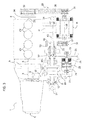
- Figure 2 illustrates a variant, which has also already been proposed in the prior European patent application No. EP 13153802 , that differs from the first embodiment of Figure 1 in that the electric machine M has its axis arranged parallel to and at a distance from the axes of the output shafts 12, 13 of the differential D.
- the connection between the shaft 16 of the electric machine M and the second crown wheel 19 of the differential D is obtained by means of three gear-reduction jumps.
- a first jump is obtained by means of the pair of gears 35, 36.
- a second jump is obtained by means of the pair of gears 37, 21, and a third jump is obtained by means of the pair of gears 22, 19.
- the gears 36, 37 are carried by a hollow shaft 40 that is mounted freely rotatable within the casing 28 via rolling bearings 41.
- the hollow shaft 40 is traversed by the output shaft 13 of the differential D.
- the gears 21, 22 are arranged as described with reference to Figure 1 , in association with shafts 23, 24 that can be connected together by means of the electromagnetically governed engagement device 25.
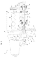
- Figure 3 illustrates an embodiment that does not form the subject of the present invention. However, the description of this embodiment is useful for an understanding of the present invention.
- the solution of Figure 3 has in common with the solutions of Figures 1 and 2 both provision of an engagement device 25 between the electric machine M and the differential D and provision of a connection, for example obtained by means of the belt transmission 29, between the shaft of the electric machine M and the shaft 5 of the internal-combustion engine E, on the side opposite to the gearbox device.
- the transmission that connects the shaft 16 of the electric machine M with the crown wheel 19 of the differential D includes a gear-reduction jump constituted by a belt transmission 50.
- the belt transmission 50 constitutes a first gear-reduction jump. It comprises a belt 51 engaged on a pulley 52 connected to the shaft 16 of the electric machine M. The belt 51 is moreover engaged on a pulley 53 connected on the hollow shaft 40 already described with reference to Figure 2 . Downstream of the belt transmission 50, the transmission remains identical to that of Figure 2 , with the two pairs of gears 37, 21 and 22, 19, with the gears 21 and 22 arranged coaxially and connected by the engagement device 25.
- Provision of the transmission between the electric machine and the differential with at least one gear-reduction jump constituted by a belt transmission enables a high flexibility in the positioning of the electric machine, this representing a considerable advantage above all in small-sized motor vehicles.
- the configuration and arrangement of the belt transmission may even differ from what is illustrated by way of example in Figure 3 .
- the total number of gear-reduction jumps could be other than three, and the belt transmission 50 could be used for a gear-reduction jump subsequent to the first one.
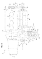
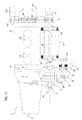
- Figure 4 illustrates an example of embodiment of the invention.
- a first difference as compared to the embodiment of Figure 3 lies in the fact that, in this case, the gears 21, 22 are directly connected together, being both rigidly connected to a common shaft 23, whilst the engagement device 25, with the associated electromagnetic actuator 26, is arranged between the shaft 16 of the electric machine M and the pulley 52 of the belt transmission 50 in a position coaxial with the electric machine M.
- the engagement device 34 is not arranged between the shaft 5 of the internal-combustion engine and the pulley 32 of the belt transmission 29.
- the engagement device 34 provided with an electromagnetic actuator 34a, is arranged between the shaft of the electric machine M and the pulley 31 of the belt transmission 29. Consequently, in the embodiment of Figure 4 , the two engagement devices 25 and 34 are both coaxial to the shaft 16 of the electric machine M and are arranged on opposite sides with respect to the electric machine M.
- the pulley 31 and the pulley 52 are mounted on respective coaxial hollow shafts at the opposite ends of the shaft of the electric machine M and are connected to the latter by means of the engagement devices 34 and 25.
- the pulley 31 in this case is axially arranged between the electric machine and the engagement device 34.
- Each of the actuators 26 and 34a is controlled by the electronic control unit U (see Figure 1 ) on the basis of the operating conditions of the engine E.
- Figure 5 shows a further variant that does not form the subject of the present invention and that has the engagement device 25 arranged between the gears 21 and 22, as in Figure 3 , and the engagement device 34 that is arranged between the shaft 16 of the electric machine M and the pulley 31, as in Figure 4 .
- the ensemble of the engagement device 34 and the actuator 34a is arranged axially between the pulley 31 and the electric machine M.
- the latter characteristic may be adopted also in the embodiment according to the invention that is illustrated in Figure 4 .
- Figure 6 illustrates a further embodiment of the present invention.
- the transmission between the shaft 16 of the electric machine M and the differential D comprises a reducer R having a casing 54 rigidly connected to the casing of the differential D and adapted to provide two gear-reduction jumps.
- the first jump is provided by means of a gear 55 connected to a shaft, which is in turn directly connected to the shaft 16 of the electric machine M, on the prolongation thereof.
- the gear 55 meshes with a gear 56 of a shaft 58, which is parallel to the shaft 13 of the differential and to the shaft 16 of the electric machine and is arranged in an intermediate position between them.
- a gear 57 that meshes with the second crown wheel 19 of the differential D, which in this case is carried by a gear connected to a hollow shaft 19', which is in turn connected to the gear-train carrier of the differential and is arranged coaxially with respect to the shaft 13 of the differential.
- Figure 7 illustrates a further embodiment of the present invention.
- the electric machine M is mounted coaxially with the differential D, as in Figure 1 . Consequently, in the case of Figure 7 , as in Figure 1 , the shaft 16 is a hollow shaft and is traversed by the output shaft 13 of the differential.
- the transmission between the electric machine M and the differential D corresponds to the two final gear-reduction jumps of Figure 4 , with the pairs of gears 37, 21 and 22, 19 and with the gears 21, 22 directly connected together via a common shaft 23.
- Figure 9 illustrates a further embodiment of the invention, which differs from that of Figure 7 in that the second crown wheel 19 of the differential is carried by a gear connected to a hollow shaft 19', which is in turn connected to the gear-train carrier of the differential and that is arranged coaxially with respect to the shaft 13 of the differential (as in Figure 6 ).
- Figures 10 and 11 show variants that do not envisage the main characteristic forming the subject of the invention, but present additional characteristics that can in any case be adopted also in the case of the present invention.
- These figures refer to two different embodiments adapted to be applied to vehicles with four-wheel drive, in which the transmission that connects the shaft 16 of the electric machine M to the second crown wheel 19 of the differential D includes a gear for driving a transmission shaft connected to a further axle (in the example the rear axle) of the vehicle. This connection to a further axle of the vehicle could be adopted also in the case of the present invention.
- Both of the examples of Figures 10 and 11 refer to the case of electric an machine M arranged coaxially with respect to the shafts 12, 13 of the differential, with two gear-reduction jumps constituted by the pairs of gears 37, 21 and 22, 19 and with the engagement device 25 arranged between the two coaxial gears 21, 22.
- the gear for driving the transmission shaft connected to the further axle of the vehicle is a bevel gear 59, arranged, in the transmission, between the second crown wheel 19 of the differential D and the engagement device 25.
- the gear 59 is mounted on the shaft 24 and meshes with a bevel gear 60 having its axis orthogonal to the axis of the shaft 24.
- the bevel gear 60 is rigidly connected to the transmission shaft 61 that transmits power to the other axle of the vehicle, preferably via a joint 62 of any known type.
- the gear for driving the transmission shaft connected to the further axle of the vehicle is a bevel gear 59, arranged, in the transmission, between the engagement device 25 and the shaft 16 of the electric machine M.
- the gear 59 is mounted on the shaft 23 and meshes with a bevel gear 60 having its axis orthogonal to the axis of the shaft 23.
- the bevel gear 60 is rigidly connected to the transmission shaft 61 that transmits power to the other axle of the vehicle via a joint 62.
- the torque of the electric machine is shared between the front axle and the rear axle in a way identical to what occurs as regards the torque of the internal-combustion engine, whereas, in the case of Figure 11 , the functions of the electric machine are irrespective of the distribution of the torque of the internal-combustion engine, and it may even be envisaged that 100% of the torque of the internal-combustion engine is transmitted to the front axle of the motor vehicle and 100% of the torque of the electric machine is transmitted to the rear axle.
- Figures 12 and 13 show variants that do not envisage the main characteristic forming the subject of the invention, but that present additional characteristics that can in any case be adopted also in the case of the present invention.
- the belt transmission 29 controls also one or more auxiliary devices of the motor vehicle, such as, for example, a compressor CO of an air-conditioning system and a source of negative pressure VS for the braking system.
- auxiliary belt transmission 29 is engaged on pulleys 63, 64 for actuation of said auxiliary devices.
- the pulley 32 of the belt transmission 29 is connected in rotation with a pulley 65 that controls, by means of a further belt transmission 66, the auxiliary devices CO and VS.
- the belt transmission 66 connects the pulley 65 to a pulley 67 connected to a tubular shaft 68 coaxial with the tubular shaft 16 of the electric machine (in Figures 10 and 11 , the electric machine is coaxial with the shafts 12, 13 of the differential).
- the shaft 68 is connected to the shaft 16 via an engagement device 69.
Landscapes
- Engineering & Computer Science (AREA)
- Mechanical Engineering (AREA)
- Chemical & Material Sciences (AREA)
- Combustion & Propulsion (AREA)
- Transportation (AREA)
- Hybrid Electric Vehicles (AREA)
- General Engineering & Computer Science (AREA)
- Gear Transmission (AREA)
- Structure Of Transmissions (AREA)
- Arrangement Of Transmissions (AREA)
Abstract
Description
- The present invention relates to a hybrid powertrain unit for motor vehicles, of the type comprising:
- an internal-combustion engine; and
- a gearbox device including:
- at least one primary shaft that can be connected to the crankshaft of the motor vehicle by means of a clutch device;
- at least one secondary shaft, the axis of which is parallel and arranged at a distance from the axis of said primary shaft, and which carries an output pinion;
- a plurality of pairs of gears corresponding to a plurality of forward gear ratios, in which the gears of each pair are rigidly connected in rotation with respect to one between said primary shaft and said secondary shaft, and the other is freely rotatable with respect to the other of said primary and secondary shafts; and
- a plurality of gear-selection devices for coupling in rotation each of said freely rotatable gears with the shaft on which it is mounted,
- a differential, having a first crown wheel meshing with said output pinion of said secondary shaft of the gearbox device; and
- an electric machine adapted to operate both as electric motor and as electric generator, and having a casing rigidly connected to a supporting structure of said powertrain unit, and a shaft connected by means of a transmission to a second crown wheel of said differential.
- A hybrid powertrain unit of the type referred to above is known, for example, from
EP 1 868 832 B1DE 10 2009 0566366 A1 US 2002/065163 A1 also disclose a hybrid powertrain unit of the type referred to above, which also comprises an engagement device arranged, in the connecting transmission, between the shaft of the electric machine and the aforesaid second crown wheel of the differential, and means for actuating the aforesaid engagement device. - It should likewise be noted that in European patent application
EP 13153802 - The object of the present invention is to provide a hybrid powertrain unit that will have a simple structure and small overall dimensions and that will be efficient, reliable, and versatile in operation.
- With a view to achieving the above purpose, the subject of the invention is a hybrid powertrain unit of the type specified above, with the engagement device arranged between the shaft of the electric machine and the second crown wheel of the differential, the unit being further characterized in that:
- the electric machine has a shaft connected to the shaft of the internal-combustion engine to the end of the latter opposite to the end connected to the gearbox device, by means of a belt transmission including an endless belt engaged on a first pulley connected to the shaft of the electric machine and on a second pulley connected to the shaft of the internal-combustion engine;
- arranged between the shaft (16) of the electric machine (E) and said first pulley (31) is a second engagement device (34); and
- said first and second engagement devices (25, 34) are both arranged coaxially with the shaft of the electric machine, on each of the opposite sides with respect to the electric machine (E).
- Direct connection between the shaft of the internal-combustion engine and the shaft of the electric machine makes it possible to provide, for example, a function of the electric machine as BAS (Belt Alternator Starter), i.e., as generator driven by the engine or as electric motor for starting the internal-combustion engine.
- In a preferred embodiment, the aforesaid first engagement device and second engagement device are clutch engagement devices provided with actuator means comprising an electromagnetic or electrohydraulic actuator and an electronic unit for controlling the actuators.
- Activation of the engagement devices is controlled independently by the electronic control unit of the motor vehicle according to a pre-arranged program, as a function of the operating parameters of the engine and of the motor vehicle.
- Use of the engagement device in the connection between the differential and the electric machine enables the connection to be made in the operating conditions where this is desired, to the advantage of efficiency of the system.
- In a variant, the above transmission that connects the shaft of the electric machine to the aforesaid second crown wheel of the differential includes a gear for driving a transmission shaft connected to a further axle of the vehicle.
- Provision in the unit according to the invention of a gear for driving a transmission shaft connected to a further axle of the vehicle enables efficient application to vehicles with four-wheel drive. The aforesaid gear for driving the transmission shaft connected to the further axle of the vehicle may be arranged, for example, between the second crown wheel of the differential and the engagement device, or else alternatively between the engagement device and the shaft of the electric machine. In the former case, the torque of the electric machine is shared between the front axle and the rear axle in a way identical to what occurs for the torque of the internal-combustion engine, whereas in the latter case the functions of the electric machine are irrespective of the distribution of the torque of the internal-combustion engine and may even envisage that 100% of the torque of the internal-combustion engine is transmitted to the front axle of the motor vehicle and 100% of the torque of the electric machine is transmitted to the rear axle.
- In a further embodiment, the above transmission that connects the shaft of the electric machine to said second crown wheel of the differential includes at least one gear-reduction jump constituted by a belt transmission.
- Further characteristics of the invention are indicated in the annexed independent claims, which form an integral part of the description of the invention.
- The invention will now be illustrated with reference to the annexed drawings, which are provided purely by way of non-limiting example and in which:
-
Figure 1 is a schematic view of a first embodiment of a powertrain unit that has been already proposed by the present applicant in European patent applicationEP 13153802 -
Figure 2 is a schematic view of a variant of the powertrain unit ofFigure 1 , likewise already proposed by the present applicant in European patent applicationEP 13153802 -
Figures 3-11 illustrate variants that do not envisage auxiliary devices of the motor vehicle associated to the engine unit according to the main characteristic of the present invention; however, the description of these variants is useful in so far as they include characteristics that can be adopted also in the case of the present invention; -
Figure 12 shows an embodiment with auxiliary devices controlled by the belt transmission that directly connects the shaft of the electric machine to the shaft of the internal-combustion engine, according to what is already envisaged in the European patent application No.EP 13153802 -
Figure 13 illustrates an embodiment according to the present invention. - In
Figures 1-13 , parts in common are designated by the same reference numbers. In said figures,number 1 designates as a whole a hybrid powertrain unit for motor vehicles, comprising an internal-combustion engine E, a gearbox device C, a differential D, and an electric machine M. - According to the conventional art, the gearbox device C has a
casing 2, rotatably mounted inside which is aprimary shaft 3 by means ofrolling bearings 4. The primary shaft can be connected to theshaft 5 of the engine E via aclutch device 6 of any known type. Moreover, rotatably mounted inside thecasing 2 of the gearbox C, viarolling bearings 8, is asecondary shaft 7. The axis of thesecondary shaft 7 is parallel to and arranged at a distance from the axis of theprimary shaft 3. - Of course, even though the annexed drawings show a gearbox of the conventional type, which includes a single primary shaft and a single secondary shaft, the invention applies to any other known configuration of the gearbox device, including, in particular, the configurations that envisage two coaxial primary shafts that can be connected selectively to the crankshaft by means of a double-clutch device and have any number of secondary shafts.
- To return to the configuration illustrated in the drawings by way of example, the
primary shaft 3 and thesecondary shaft 7 carry pairs of gears meshing together to provide a plurality of forward gear ratios. One gear of each pair is rigidly connected to the shaft by which it is carried, whereas the other gear of each pair is mounted freely rotatable on the respective shaft. - In the case of the example illustrated, the first gear ratio is obtained by a pair of gears including a gear I1 rigidly connected to the
primary shaft 3 and a gear I2 mounted freely rotatable on thesecondary shaft 7. The second gear ratio is obtained by means of a gear II1 rigidly connected to theprimary shaft 3 and a gear II2 mounted freely rotatable on thesecondary shaft 7. The third, fourth, fifth, and sixth gear ratios are obtained by means of pairs of gears including gears III1, IV1, V1, VI1 rigidly connected to thesecondary shaft 7 and corresponding gears III2, IV2, V2 and VI2 mounted freely rotatable on theprimary shaft 3. - Once again according to the known art, the primary and
secondary shafts - The gearbox device C further comprises a third shaft (not visible in the plate of drawings), which carries in a freely rotatable way a reverse gear and a selection device for connecting said gear in rotation to the respective shaft in such a way as to transmit the motion of rotation of the
primary shaft 3 to thesecondary shaft 7 with a reversal of the direction of rotation. - The
secondary shaft 7 carries anoutput pinion 9 meshing with afirst crown wheel 10 of the differential D. The differential D, which has a structure of a type in itself known, has acasing 11 rigidly connected to thecasing 2 of the gearbox device C and has twooutput shafts universal joints 14. Thecrown wheel 10 is rigidly connected to the gear-train carrier of the differential, which is rotatably mounted within thecasing 11 by means ofbearings 15. - The electric machine M is adapted to function both as electric motor and as electric generator, according to the operating conditions. In the embodiment illustrated in
Figure 1 , the electric machine M shares the axes of the twooutput shafts shaft 16 is hollow and is in turn axially traversed by theoutput shaft 13 of the differential D so as to enable aligned arrangement of the electric machine M with the differential D. Thecasing 17 of the electric machine M is rigidly connected to thecasing 11 of the differential D and possibly also to the structure of the internal-combustion engine E. Theshaft 16 of the electric machine M is rotatably supported within thecasing 17 viarolling bearings 18. - The
shaft 16 of the electric machine M is connected in rotation to asecond crown wheel 19 of the differential D rigidly connected to the gear-train carrier of the differential. In the case ofFigure 1 , the connection between theshaft 16 of the electric machine M and thecrown wheel 19 of the differential D is obtained by a double gear-reduction jump, obtained by means of a first pair ofgears gears gear 20 is rigidly connected to theshaft 16 of the electric machine M, whereas thegears shafts engagement device 25, which, in the case of the example illustrated, is a clutch device controlled by anelectromagnetic actuator 26, which is in turn driven by an electronic control unit U (illustrated schematically only inFigure 1 ). The actuator could also be of an electrohydraulic type, or of any other known type. Also the engagement device could be of any other known type. The twoshafts rolling bearings 27 within acasing 28 of the gear-reduction transmission, which is rigidly connected to thecasing 11 of the differential D and with thecasing 17 of the electric machine M. - With reference to the specific example illustrated, the
engagement device 25 and theelectromagnetic actuator 26 may be obtained in any known way. For these reasons, the constructional details of said elements are not illustrated herein, also in order to render the drawings simpler and of easier to understand. - Finally, designated as a whole by CY are the cylinders of the engine that are arranged vertically in the condition where the unit is mounted on the motor vehicle. Consequently, the views illustrated in
Figures 1-4 are top plan views, with reference to the arrangement where the powertrain unit is mounted in the motor vehicle. Typically, the unit is mounted in the front part of the motor vehicle, in association with the front wheels of the motor vehicle. - The electric machine M functions as electric motor or as generator, according to the operating conditions of the engine and of the motor vehicle. In particular, the following different operating modes are possible:
- electric drive (internal-combustion engine E turned off and gearbox in neutral);
- hybrid drive (internal-combustion engine turned on and gearbox with a gear engaged); and
- recovery of energy during braking (internal-combustion engine turned on and gear in neutral or else clutch 6 between the internal-combustion engine and gearbox disengaged).
- The electric machine M may moreover be used as electric motor for filling the gap in the torque supplied by the internal-combustion engine to the wheels of the vehicle during gear change.
- Finally, the
engagement device 25 enables decoupling of the electric machine M in the operating conditions in which intervention thereof is not required. - As already mentioned,
Figure 1 of the annexed drawings regards a solution already proposed by the present applicant in the European patent application No.EP 13153802 shaft 16 of the electric machine M to theshaft 5 of the internal-combustion engine E, at the end of the engine E opposite to the one connected to the gearbox device C. For this purpose, in the example illustrated, anauxiliary belt transmission 29 is provided, including anendless belt 30 engaged on afirst pulley 31 carried by theshaft 16 of the electric machine M and on asecond pulley 32 carried by theshaft 33 that can be connected to theshaft 5 of the internal-combustion engine via anengagement device 34, for example, an electromagnetically governed one or one of any other known type. An engagement device of this type is, for example, described and illustrated in the document No.EP 1 529 957 A1 - The
belt transmission 29 and theengagement device 34 enable direct connection of the shaft of the internal-combustion engine to the shaft of the electric machine M to provide, for example, a function of the electric machine as BAS (Belt Alternator Starter), i.e., as a generator driven by the engine or as electric motor for starting the internal-combustion engine. - In the modality of starting of the internal-combustion engine, the
engagement device 25 is disengaged and theengagement device 34 is engaged. - In the modality of generation of current with the vehicle standing still, the internal-combustion engine is turned on, the
engagement device 25 is disengaged, and theengagement device 34 is engaged. - In vehicles equipped with a stop-and-go device, in which the internal-combustion engine turns off automatically when the vehicle is stationary, the electric machine M makes it possible to keep auxiliary devices governed by the
belt 30 functioning (such as the compressor of the air-conditioning system). In this condition, theengagement device 34 is disengaged. -
Figure 2 illustrates a variant, which has also already been proposed in the prior European patent application No.EP 13153802 Figure 1 in that the electric machine M has its axis arranged parallel to and at a distance from the axes of theoutput shafts shaft 16 of the electric machine M and thesecond crown wheel 19 of the differential D is obtained by means of three gear-reduction jumps. A first jump is obtained by means of the pair ofgears gears gears gears hollow shaft 40 that is mounted freely rotatable within thecasing 28 via rollingbearings 41. Thehollow shaft 40 is traversed by theoutput shaft 13 of the differential D. In the embodiment ofFigure 3 , thegears Figure 1 , in association withshafts engagement device 25. -
Figure 3 illustrates an embodiment that does not form the subject of the present invention. However, the description of this embodiment is useful for an understanding of the present invention. The solution ofFigure 3 has in common with the solutions ofFigures 1 and2 both provision of anengagement device 25 between the electric machine M and the differential D and provision of a connection, for example obtained by means of thebelt transmission 29, between the shaft of the electric machine M and theshaft 5 of the internal-combustion engine E, on the side opposite to the gearbox device. - The main difference with respect to the solutions of
Figures 1 and2 lies in the fact that, in the case ofFigure 3 , the transmission that connects theshaft 16 of the electric machine M with thecrown wheel 19 of the differential D includes a gear-reduction jump constituted by abelt transmission 50. In the example illustrated, thebelt transmission 50 constitutes a first gear-reduction jump. It comprises abelt 51 engaged on apulley 52 connected to theshaft 16 of the electric machine M. Thebelt 51 is moreover engaged on apulley 53 connected on thehollow shaft 40 already described with reference toFigure 2 . Downstream of thebelt transmission 50, the transmission remains identical to that ofFigure 2 , with the two pairs ofgears gears engagement device 25. - Provision of the transmission between the electric machine and the differential with at least one gear-reduction jump constituted by a belt transmission enables a high flexibility in the positioning of the electric machine, this representing a considerable advantage above all in small-sized motor vehicles.
- Of course, the configuration and arrangement of the belt transmission may even differ from what is illustrated by way of example in
Figure 3 . For example, the total number of gear-reduction jumps could be other than three, and thebelt transmission 50 could be used for a gear-reduction jump subsequent to the first one. In theory, it would also be possible to provide the electric machine aligned with the differential, as in the solution ofFigure 1 , and use thebelt transmission 50 for connecting the shaft of the electric machine with a parallel shaft arranged at a distance apart, which is in turn connected to a gear meshing with thecrown wheel 19 of the differential. - It should moreover be noted that a further difference as compared to
Figure 2 lies in the fact that inFigure 3 the electric machine M is supported, in an off-axis position with respect to the differential D, directly by the structure of the internal-combustion engine E, via a supporting structure H of any type, which is illustrated schematically in the drawing. -
Figure 4 illustrates an example of embodiment of the invention. A first difference as compared to the embodiment ofFigure 3 lies in the fact that, in this case, thegears common shaft 23, whilst theengagement device 25, with the associatedelectromagnetic actuator 26, is arranged between theshaft 16 of the electric machine M and thepulley 52 of thebelt transmission 50 in a position coaxial with the electric machine M. - Once again in the case of
Figure 4 , theengagement device 34 is not arranged between theshaft 5 of the internal-combustion engine and thepulley 32 of thebelt transmission 29. In this case, theengagement device 34, provided with anelectromagnetic actuator 34a, is arranged between the shaft of the electric machine M and thepulley 31 of thebelt transmission 29. Consequently, in the embodiment ofFigure 4 , the twoengagement devices shaft 16 of the electric machine M and are arranged on opposite sides with respect to the electric machine M. - In the solution of
Figure 4 , thepulley 31 and thepulley 52 are mounted on respective coaxial hollow shafts at the opposite ends of the shaft of the electric machine M and are connected to the latter by means of theengagement devices pulley 31 in this case is axially arranged between the electric machine and theengagement device 34. - Each of the
actuators Figure 1 ) on the basis of the operating conditions of the engine E. -
Figure 5 shows a further variant that does not form the subject of the present invention and that has theengagement device 25 arranged between thegears Figure 3 , and theengagement device 34 that is arranged between theshaft 16 of the electric machine M and thepulley 31, as inFigure 4 . In this case, however, the ensemble of theengagement device 34 and theactuator 34a is arranged axially between thepulley 31 and the electric machine M. The latter characteristic may be adopted also in the embodiment according to the invention that is illustrated inFigure 4 . -
Figure 6 illustrates a further embodiment of the present invention. In this variant, the transmission between theshaft 16 of the electric machine M and the differential D comprises a reducer R having acasing 54 rigidly connected to the casing of the differential D and adapted to provide two gear-reduction jumps. The first jump is provided by means of agear 55 connected to a shaft, which is in turn directly connected to theshaft 16 of the electric machine M, on the prolongation thereof. Thegear 55 meshes with agear 56 of ashaft 58, which is parallel to theshaft 13 of the differential and to theshaft 16 of the electric machine and is arranged in an intermediate position between them. Also connected on theshaft 58 is a gear 57 that meshes with thesecond crown wheel 19 of the differential D, which in this case is carried by a gear connected to a hollow shaft 19', which is in turn connected to the gear-train carrier of the differential and is arranged coaxially with respect to theshaft 13 of the differential. -
Figure 7 illustrates a further embodiment of the present invention. In this case, unlike inFigure 6 , the electric machine M is mounted coaxially with the differential D, as inFigure 1 . Consequently, in the case ofFigure 7 , as inFigure 1 , theshaft 16 is a hollow shaft and is traversed by theoutput shaft 13 of the differential. Once again in the case of the variant ofFigure 7 , the transmission between the electric machine M and the differential D corresponds to the two final gear-reduction jumps ofFigure 4 , with the pairs ofgears gears common shaft 23. - The variant of
Figure 8 does not form the subject of the invention in so far as here theengagement device 25 is arranged between thegears -
Figure 9 illustrates a further embodiment of the invention, which differs from that ofFigure 7 in that thesecond crown wheel 19 of the differential is carried by a gear connected to a hollow shaft 19', which is in turn connected to the gear-train carrier of the differential and that is arranged coaxially with respect to theshaft 13 of the differential (as inFigure 6 ). -
Figures 10 and11 show variants that do not envisage the main characteristic forming the subject of the invention, but present additional characteristics that can in any case be adopted also in the case of the present invention. These figures refer to two different embodiments adapted to be applied to vehicles with four-wheel drive, in which the transmission that connects theshaft 16 of the electric machine M to thesecond crown wheel 19 of the differential D includes a gear for driving a transmission shaft connected to a further axle (in the example the rear axle) of the vehicle. This connection to a further axle of the vehicle could be adopted also in the case of the present invention. - Both of the examples of
Figures 10 and11 refer to the case of electric an machine M arranged coaxially with respect to theshafts gears engagement device 25 arranged between the twocoaxial gears - In the case of
Figure 10 , the gear for driving the transmission shaft connected to the further axle of the vehicle is abevel gear 59, arranged, in the transmission, between thesecond crown wheel 19 of the differential D and theengagement device 25. Thegear 59 is mounted on theshaft 24 and meshes with abevel gear 60 having its axis orthogonal to the axis of theshaft 24. Thebevel gear 60 is rigidly connected to thetransmission shaft 61 that transmits power to the other axle of the vehicle, preferably via a joint 62 of any known type. - In the case of
Figure 11 , the gear for driving the transmission shaft connected to the further axle of the vehicle is abevel gear 59, arranged, in the transmission, between theengagement device 25 and theshaft 16 of the electric machine M. Thegear 59 is mounted on theshaft 23 and meshes with abevel gear 60 having its axis orthogonal to the axis of theshaft 23. Thebevel gear 60 is rigidly connected to thetransmission shaft 61 that transmits power to the other axle of the vehicle via a joint 62. - In the case of
Figure 10 , the torque of the electric machine is shared between the front axle and the rear axle in a way identical to what occurs as regards the torque of the internal-combustion engine, whereas, in the case ofFigure 11 , the functions of the electric machine are irrespective of the distribution of the torque of the internal-combustion engine, and it may even be envisaged that 100% of the torque of the internal-combustion engine is transmitted to the front axle of the motor vehicle and 100% of the torque of the electric machine is transmitted to the rear axle. -
Figures 12 and13 show variants that do not envisage the main characteristic forming the subject of the invention, but that present additional characteristics that can in any case be adopted also in the case of the present invention. In these variants, thebelt transmission 29 controls also one or more auxiliary devices of the motor vehicle, such as, for example, a compressor CO of an air-conditioning system and a source of negative pressure VS for the braking system. - In the case of
Figure 12 , theauxiliary belt transmission 29 is engaged onpulleys - In the case of
Figure 13 , which illustrates an embodiment of the present invention, thepulley 32 of thebelt transmission 29 is connected in rotation with apulley 65 that controls, by means of afurther belt transmission 66, the auxiliary devices CO and VS. Thebelt transmission 66 connects thepulley 65 to apulley 67 connected to a tubular shaft 68 coaxial with thetubular shaft 16 of the electric machine (inFigures 10 and11 , the electric machine is coaxial with theshafts shaft 16 via anengagement device 69. - Use of the
belt transmission 29 for control of auxiliary devices could be envisaged also in the case of the present invention - Of course, without prejudice to the principle of the invention, the details of construction and the embodiments may vary widely with respect to what has been described and illustrated herein purely by way of example, without thereby departing from the scope of the present invention.
Claims (8)
- A hybrid powertrain unit for a motor vehicle, comprising:- an internal-combustion engine (E); and- a gearbox device (C) including:- at least one primary shaft (3), that can be connected to the crankshaft (5) of the motor vehicle by means of a clutch device (6),- at least one secondary shaft (7), the axis of which is parallel to and at a distance from by the axis of said primary shaft (3) and which carries an output pinion (9);- a plurality of pairs of gears (I1, I2, II1, II2, III1, III2, IV1, IV2, V1, V2, VI1, VI2) corresponding to a plurality of forward gear ratios (I, II, III, IV, V, VI), in which the gears of each pair are one rigidly connected in rotation with respect to one of said primary and secondary shafts (3, 7) and the other freely rotatable with respect to the other of said primary and secondary shafts; and- a plurality of gear-selection devices (S1/2, S3/4, S5/6) for coupling in rotation each of said freely rotatable gears with the shaft main characteristic of the invention,said unit further comprising:- a differential (D), having a first crown wheel (10) meshing with said output pinion (9) of said secondary shaft (7) of the gearbox device (C);- an electric machine (M) adapted to operate both as electric motor and as electric generator and having a casing (17) rigidly connected to a supporting structure of said powertrain unit, and a shaft (16) connected by means of a transmission to a second crown wheel (19) of said differential;- a first engagement device (25) arranged, in said connecting transmission, between the shaft (16) of the electric machine (M) and the aforesaid second crown wheel (19) of the differential (D); and- means (26) for actuating said engagement device,said powertrain unit being characterized in that:- the electric machine (M) has a shaft (16) connected to the shaft (5) of the internal-combustion engine (E) at the end thereof opposite to the end connected to the gearbox device (C) by means of a belt transmission (29) including an endless belt (30) engaged on a first pulley (31) connected to the shaft (16) of the electric machine (M) and on a second pulley (32) connected to the shaft (5) of the internal-combustion engine (E);- arranged between the shaft (16) of the electric machine (E) and said first pulley (31) is a second engagement device (34); and- said first and second engagement devices (25, 34) are both arranged coaxially with respect to the shaft of the electric machine, respectively on opposite sides with respect to the electric machine (E).
- The unit according to Claim 1, characterized in that said first engagement device (25) and said second engagement device are clutch engagement devices (25, 34) provided with actuator means comprising an electromagnetic or electrohydraulic actuator (26, 34a) and an electronic unit (U) for control of said actuator (26, 34a).
- The unit according to Claim 1, characterized in that said first pulley (31) is mounted on a hollow shaft coaxial to the shaft (16) of the electric machine (E) and connected thereto by means of said second engagement device (34).
- The unit according to Claim 3, characterized in that said first pulley (31) is axially arranged between the electric machine (E) and said second engagement device (34).
- The unit according to Claim 3, characterized in that said second engagement device (34) is axially arranged between the electric machine (E) and said first pulley (31).
- The unit according to Claim 1, characterized in that said transmission that connects the shaft (16) of the electric machine (M) to said second crown wheel (19) of the differential (D) includes at least one gear-reduction jump constituted by a belt transmission (50).
- The unit according to Claim 1, characterized in that said transmission that connects the shaft (16) of the electric machine (M) to said second crown wheel (19) of the differential (D) includes a gear (59) for driving a transmission shaft connected to a further axle of the vehicle.
- The unit according to Claim 1, characterized in that it comprises one or more auxiliary devices of the motor vehicle, such as, for example, a compressor for an air-conditioning system (CO) and a source of negative pressure (VS) for the braking system, and in that said belt transmission (29) controls said one or more auxiliary devices
Priority Applications (6)
| Application Number | Priority Date | Filing Date | Title |
|---|---|---|---|
| EP14172693.5A EP2957445B1 (en) | 2014-06-17 | 2014-06-17 | Hybrid powertrain unit for motor vehicles with engagement devices on opposite sides of the electric machine |
| JP2015014107A JP6729854B2 (en) | 2014-06-17 | 2015-01-28 | Hybrid power transmission unit for motor vehicles with engagement devices on opposite sides of electric machine |
| KR1020150063733A KR102315151B1 (en) | 2014-06-17 | 2015-05-07 | Hybrid powertrain unit for motor vehicles with engagement devices on opposite sides of the electric machine |
| US14/714,604 US9573457B2 (en) | 2014-06-17 | 2015-05-18 | Hybrid powertrain unit for motor vehicles with engagement devices on opposite sides of the electric machine |
| BR102015014138-6A BR102015014138B1 (en) | 2014-06-17 | 2015-06-16 | HYBRID DRIVE UNIT FOR MOTOR VEHICLES WITH COUPLING DEVICES ON OPPOSITE SIDES OF THE ELECTRIC MACHINE |
| CN201510331434.4A CN105270160B (en) | 2014-06-17 | 2015-06-16 | The hybrid powertrain unit of motor vehicles |
Applications Claiming Priority (1)
| Application Number | Priority Date | Filing Date | Title |
|---|---|---|---|
| EP14172693.5A EP2957445B1 (en) | 2014-06-17 | 2014-06-17 | Hybrid powertrain unit for motor vehicles with engagement devices on opposite sides of the electric machine |
Publications (2)
| Publication Number | Publication Date |
|---|---|
| EP2957445A1 true EP2957445A1 (en) | 2015-12-23 |
| EP2957445B1 EP2957445B1 (en) | 2016-09-14 |
Family
ID=51224670
Family Applications (1)
| Application Number | Title | Priority Date | Filing Date |
|---|---|---|---|
| EP14172693.5A Not-in-force EP2957445B1 (en) | 2014-06-17 | 2014-06-17 | Hybrid powertrain unit for motor vehicles with engagement devices on opposite sides of the electric machine |
Country Status (6)
| Country | Link |
|---|---|
| US (1) | US9573457B2 (en) |
| EP (1) | EP2957445B1 (en) |
| JP (1) | JP6729854B2 (en) |
| KR (1) | KR102315151B1 (en) |
| CN (1) | CN105270160B (en) |
| BR (1) | BR102015014138B1 (en) |
Cited By (1)
| Publication number | Priority date | Publication date | Assignee | Title |
|---|---|---|---|---|
| WO2018041914A1 (en) * | 2016-08-31 | 2018-03-08 | Borgwarner Sweden Ab | Chain tensioning in a hybrid drive module |
Families Citing this family (7)
| Publication number | Priority date | Publication date | Assignee | Title |
|---|---|---|---|---|
| US9441599B2 (en) * | 2012-07-17 | 2016-09-13 | Altigreen Propulsion Labs Private Limited | Induction motor-permanent magnet generator tandem configuration starter-generator for hybrid vehicles |
| US9580065B2 (en) | 2012-07-17 | 2017-02-28 | Altigreen Propulsion Labs Private Limited | Dual-structured electric drive and power system for hybrid vehicles |
| EP2979911B1 (en) * | 2014-07-29 | 2016-09-21 | C.R.F. Società Consortile per Azioni | Hybrid powertrain unit for motor vehicles with a variable transmission device between electric machine and differential |
| US10106024B2 (en) * | 2016-10-18 | 2018-10-23 | Gm Global Technology Operation Llc | Hybrid manual transmission |
| CN106945498B (en) * | 2017-03-28 | 2019-05-03 | 上海中科深江电动车辆有限公司 | Hybrid power plant supporting parking power generation function |
| JP7694478B2 (en) * | 2022-06-27 | 2025-06-18 | トヨタ自動車株式会社 | Vehicle drive device |
| KR20260016430A (en) * | 2024-07-26 | 2026-02-03 | 도요타지도샤가부시키가이샤 | Drive apparatus for vehicle |
Citations (9)
| Publication number | Priority date | Publication date | Assignee | Title |
|---|---|---|---|---|
| US20020065163A1 (en) | 2000-11-23 | 2002-05-30 | Daimlerchrysler Ag. | Internal combustion engine of a motor vehicle |
| EP1529957A1 (en) | 2003-11-05 | 2005-05-11 | C.R.F. Società Consortile per Azioni | "A system for transmitting motion between the shaft of an internal combustion engine of a motor vehicle and a group of auxiliary devices" |
| WO2005095141A1 (en) * | 2004-04-01 | 2005-10-13 | Ricardo Uk Limited | A method of obtaining zev creep mode in hybrid vehicles |
| EP1868832B1 (en) | 2005-04-14 | 2009-07-15 | Peugeot Citroën Automobiles S.A. | Hybrid drive chain and hybrid vehicle equipped with same |
| US20100193268A1 (en) * | 2009-02-05 | 2010-08-05 | Gm Global Technology Operations, Inc. | Hybrid vehicle drive system |
| DE102009056636A1 (en) | 2009-12-02 | 2011-06-09 | Ratiopharm Gmbh | Raltegravir polymorphs |
| DE102011010085A1 (en) * | 2011-02-01 | 2012-08-02 | Audi Ag | Motor vehicle has internal combustion engine for rotating crankshaft, which is coupled with drive train on side of internal combustion engine for wheel |
| WO2013007886A1 (en) * | 2011-07-13 | 2013-01-17 | IFP Energies Nouvelles | Drive train for a motor vehicle with hybrid drive |
| EP2727757A1 (en) * | 2011-06-28 | 2014-05-07 | Toyota Jidosha Kabushiki Kaisha | Driving force transmission device and vehicle provided with said driving force transmission device |
Family Cites Families (16)
| Publication number | Priority date | Publication date | Assignee | Title |
|---|---|---|---|---|
| JP3559889B2 (en) * | 1997-12-19 | 2004-09-02 | 日産自動車株式会社 | Hybrid vehicle control device |
| JP2002160540A (en) * | 2000-11-28 | 2002-06-04 | Aisin Seiki Co Ltd | Drive unit for hybrid vehicles |
| JP3832465B2 (en) * | 2003-10-27 | 2006-10-11 | トヨタ自動車株式会社 | Hybrid vehicle drive system |
| US7004873B2 (en) * | 2004-01-22 | 2006-02-28 | Magna Powertrain, Inc. | Transfer case with electrohydraulic clutch actuator |
| JP2007022112A (en) * | 2005-07-12 | 2007-02-01 | Daihatsu Motor Co Ltd | Motor device installing structure of hybrid vehicle |
| DE102005049707A1 (en) * | 2005-10-18 | 2007-04-26 | Zf Friedrichshafen Ag | Vehicle with a drive machine arranged in the vehicle transverse direction |
| JP2008163818A (en) * | 2006-12-28 | 2008-07-17 | Hitachi Ltd | Starter |
| DE102008036167A1 (en) * | 2008-08-02 | 2010-02-04 | Daimler Ag | In addition to equipment arrangement |
| US8087483B2 (en) * | 2009-05-26 | 2012-01-03 | GM Global Technology Operations LLC | Hybrid powertrain with torque-multiplying engine starting mechanism and method of controlling a hybrid powertrain |
| JP2011011573A (en) * | 2009-06-30 | 2011-01-20 | Nissan Motor Co Ltd | Power transmission device for vehicle and device for controlling the same |
| JP5383544B2 (en) * | 2010-02-17 | 2014-01-08 | ダイハツ工業株式会社 | Automatic transmission for hybrid vehicle |
| DE102011110444A1 (en) * | 2011-08-11 | 2013-02-14 | Getrag Ford Transmissions Gmbh | Hybrid powertrain |
| US9017214B2 (en) * | 2011-10-03 | 2015-04-28 | Toyota Jidosha Kabushiki Kaisha | Hybrid vehicle control apparatus |
| US8777789B2 (en) * | 2012-01-04 | 2014-07-15 | Zf Friedrichshafen Ag | Split axis transmission hybrid system architecture |
| US9139079B2 (en) * | 2012-03-26 | 2015-09-22 | Mcmaster University | Integrated electro-mechanical powertrain system for hybrid vehicles |
| DE102013211591B4 (en) * | 2013-06-20 | 2024-03-28 | Zf Friedrichshafen Ag | Arrangement of a transmission and an electric machine for a hybrid drive and hybrid drive |
-
2014
- 2014-06-17 EP EP14172693.5A patent/EP2957445B1/en not_active Not-in-force
-
2015
- 2015-01-28 JP JP2015014107A patent/JP6729854B2/en not_active Expired - Fee Related
- 2015-05-07 KR KR1020150063733A patent/KR102315151B1/en active Active
- 2015-05-18 US US14/714,604 patent/US9573457B2/en active Active
- 2015-06-16 CN CN201510331434.4A patent/CN105270160B/en active Active
- 2015-06-16 BR BR102015014138-6A patent/BR102015014138B1/en not_active IP Right Cessation
Patent Citations (9)
| Publication number | Priority date | Publication date | Assignee | Title |
|---|---|---|---|---|
| US20020065163A1 (en) | 2000-11-23 | 2002-05-30 | Daimlerchrysler Ag. | Internal combustion engine of a motor vehicle |
| EP1529957A1 (en) | 2003-11-05 | 2005-05-11 | C.R.F. Società Consortile per Azioni | "A system for transmitting motion between the shaft of an internal combustion engine of a motor vehicle and a group of auxiliary devices" |
| WO2005095141A1 (en) * | 2004-04-01 | 2005-10-13 | Ricardo Uk Limited | A method of obtaining zev creep mode in hybrid vehicles |
| EP1868832B1 (en) | 2005-04-14 | 2009-07-15 | Peugeot Citroën Automobiles S.A. | Hybrid drive chain and hybrid vehicle equipped with same |
| US20100193268A1 (en) * | 2009-02-05 | 2010-08-05 | Gm Global Technology Operations, Inc. | Hybrid vehicle drive system |
| DE102009056636A1 (en) | 2009-12-02 | 2011-06-09 | Ratiopharm Gmbh | Raltegravir polymorphs |
| DE102011010085A1 (en) * | 2011-02-01 | 2012-08-02 | Audi Ag | Motor vehicle has internal combustion engine for rotating crankshaft, which is coupled with drive train on side of internal combustion engine for wheel |
| EP2727757A1 (en) * | 2011-06-28 | 2014-05-07 | Toyota Jidosha Kabushiki Kaisha | Driving force transmission device and vehicle provided with said driving force transmission device |
| WO2013007886A1 (en) * | 2011-07-13 | 2013-01-17 | IFP Energies Nouvelles | Drive train for a motor vehicle with hybrid drive |
Cited By (2)
| Publication number | Priority date | Publication date | Assignee | Title |
|---|---|---|---|---|
| WO2018041914A1 (en) * | 2016-08-31 | 2018-03-08 | Borgwarner Sweden Ab | Chain tensioning in a hybrid drive module |
| CN109689413A (en) * | 2016-08-31 | 2019-04-26 | 博格华纳瑞典公司 | Chain tension in combination drive module |
Also Published As
| Publication number | Publication date |
|---|---|
| JP6729854B2 (en) | 2020-07-29 |
| KR20150144692A (en) | 2015-12-28 |
| BR102015014138A8 (en) | 2022-09-20 |
| BR102015014138B1 (en) | 2022-11-29 |
| BR102015014138A2 (en) | 2016-08-16 |
| US20150360555A1 (en) | 2015-12-17 |
| JP2016003003A (en) | 2016-01-12 |
| KR102315151B1 (en) | 2021-10-20 |
| CN105270160A (en) | 2016-01-27 |
| US9573457B2 (en) | 2017-02-21 |
| EP2957445B1 (en) | 2016-09-14 |
| CN105270160B (en) | 2018-09-28 |
Similar Documents
| Publication | Publication Date | Title |
|---|---|---|
| EP2957444B1 (en) | Hybrid powertrain unit for motor vehicles with a belt transmission device between electric machine and differential | |
| EP2957446B1 (en) | Hybrid powertrain unit for motor vehicles with a device for transmission to a further axle of the motor-vehicle | |
| EP2957447B1 (en) | Hybrid powertrain unit for motor vehicles, provided with auxiliary devices | |
| EP2957445B1 (en) | Hybrid powertrain unit for motor vehicles with engagement devices on opposite sides of the electric machine | |
| EP2979911B1 (en) | Hybrid powertrain unit for motor vehicles with a variable transmission device between electric machine and differential | |
| US8926464B2 (en) | Hybrid powertrain unit for motor vehicles |
Legal Events
| Date | Code | Title | Description |
|---|---|---|---|
| PUAI | Public reference made under article 153(3) epc to a published international application that has entered the european phase |
Free format text: ORIGINAL CODE: 0009012 |
|
| 17P | Request for examination filed |
Effective date: 20150220 |
|
| AK | Designated contracting states |
Kind code of ref document: A1 Designated state(s): AL AT BE BG CH CY CZ DE DK EE ES FI FR GB GR HR HU IE IS IT LI LT LU LV MC MK MT NL NO PL PT RO RS SE SI SK SM TR |
|
| AX | Request for extension of the european patent |
Extension state: BA ME |
|
| GRAP | Despatch of communication of intention to grant a patent |
Free format text: ORIGINAL CODE: EPIDOSNIGR1 |
|
| INTG | Intention to grant announced |
Effective date: 20160429 |
|
| RIC1 | Information provided on ipc code assigned before grant |
Ipc: B60K 6/387 20071001AFI20160415BHEP Ipc: B60K 6/547 20071001ALI20160415BHEP Ipc: B60K 25/00 20060101ALN20160415BHEP Ipc: B60K 6/48 20071001ALI20160415BHEP Ipc: B60K 6/52 20071001ALI20160415BHEP Ipc: B60K 25/02 20060101ALN20160415BHEP |
|
| GRAS | Grant fee paid |
Free format text: ORIGINAL CODE: EPIDOSNIGR3 |
|
| GRAA | (expected) grant |
Free format text: ORIGINAL CODE: 0009210 |
|
| AK | Designated contracting states |
Kind code of ref document: B1 Designated state(s): AL AT BE BG CH CY CZ DE DK EE ES FI FR GB GR HR HU IE IS IT LI LT LU LV MC MK MT NL NO PL PT RO RS SE SI SK SM TR |
|
| REG | Reference to a national code |
Ref country code: GB Ref legal event code: FG4D |
|
| REG | Reference to a national code |
Ref country code: CH Ref legal event code: EP |
|
| REG | Reference to a national code |
Ref country code: IE Ref legal event code: FG4D |
|
| REG | Reference to a national code |
Ref country code: AT Ref legal event code: REF Ref document number: 828540 Country of ref document: AT Kind code of ref document: T Effective date: 20161015 |
|
| REG | Reference to a national code |
Ref country code: DE Ref legal event code: R096 Ref document number: 602014003589 Country of ref document: DE |
|
| REG | Reference to a national code |
Ref country code: LT Ref legal event code: MG4D |
|
| REG | Reference to a national code |
Ref country code: NL Ref legal event code: MP Effective date: 20160914 |
|
| PG25 | Lapsed in a contracting state [announced via postgrant information from national office to epo] |
Ref country code: RS Free format text: LAPSE BECAUSE OF FAILURE TO SUBMIT A TRANSLATION OF THE DESCRIPTION OR TO PAY THE FEE WITHIN THE PRESCRIBED TIME-LIMIT Effective date: 20160914 Ref country code: HR Free format text: LAPSE BECAUSE OF FAILURE TO SUBMIT A TRANSLATION OF THE DESCRIPTION OR TO PAY THE FEE WITHIN THE PRESCRIBED TIME-LIMIT Effective date: 20160914 Ref country code: NO Free format text: LAPSE BECAUSE OF FAILURE TO SUBMIT A TRANSLATION OF THE DESCRIPTION OR TO PAY THE FEE WITHIN THE PRESCRIBED TIME-LIMIT Effective date: 20161214 Ref country code: LT Free format text: LAPSE BECAUSE OF FAILURE TO SUBMIT A TRANSLATION OF THE DESCRIPTION OR TO PAY THE FEE WITHIN THE PRESCRIBED TIME-LIMIT Effective date: 20160914 Ref country code: FI Free format text: LAPSE BECAUSE OF FAILURE TO SUBMIT A TRANSLATION OF THE DESCRIPTION OR TO PAY THE FEE WITHIN THE PRESCRIBED TIME-LIMIT Effective date: 20160914 |
|
| REG | Reference to a national code |
Ref country code: AT Ref legal event code: MK05 Ref document number: 828540 Country of ref document: AT Kind code of ref document: T Effective date: 20160914 |
|
| PG25 | Lapsed in a contracting state [announced via postgrant information from national office to epo] |
Ref country code: SE Free format text: LAPSE BECAUSE OF FAILURE TO SUBMIT A TRANSLATION OF THE DESCRIPTION OR TO PAY THE FEE WITHIN THE PRESCRIBED TIME-LIMIT Effective date: 20160914 Ref country code: LV Free format text: LAPSE BECAUSE OF FAILURE TO SUBMIT A TRANSLATION OF THE DESCRIPTION OR TO PAY THE FEE WITHIN THE PRESCRIBED TIME-LIMIT Effective date: 20160914 Ref country code: GR Free format text: LAPSE BECAUSE OF FAILURE TO SUBMIT A TRANSLATION OF THE DESCRIPTION OR TO PAY THE FEE WITHIN THE PRESCRIBED TIME-LIMIT Effective date: 20161215 Ref country code: NL Free format text: LAPSE BECAUSE OF FAILURE TO SUBMIT A TRANSLATION OF THE DESCRIPTION OR TO PAY THE FEE WITHIN THE PRESCRIBED TIME-LIMIT Effective date: 20160914 |
|
| PG25 | Lapsed in a contracting state [announced via postgrant information from national office to epo] |
Ref country code: RO Free format text: LAPSE BECAUSE OF FAILURE TO SUBMIT A TRANSLATION OF THE DESCRIPTION OR TO PAY THE FEE WITHIN THE PRESCRIBED TIME-LIMIT Effective date: 20160914 Ref country code: EE Free format text: LAPSE BECAUSE OF FAILURE TO SUBMIT A TRANSLATION OF THE DESCRIPTION OR TO PAY THE FEE WITHIN THE PRESCRIBED TIME-LIMIT Effective date: 20160914 |
|
| PG25 | Lapsed in a contracting state [announced via postgrant information from national office to epo] |
Ref country code: SM Free format text: LAPSE BECAUSE OF FAILURE TO SUBMIT A TRANSLATION OF THE DESCRIPTION OR TO PAY THE FEE WITHIN THE PRESCRIBED TIME-LIMIT Effective date: 20160914 Ref country code: BE Free format text: LAPSE BECAUSE OF FAILURE TO SUBMIT A TRANSLATION OF THE DESCRIPTION OR TO PAY THE FEE WITHIN THE PRESCRIBED TIME-LIMIT Effective date: 20160914 Ref country code: BG Free format text: LAPSE BECAUSE OF FAILURE TO SUBMIT A TRANSLATION OF THE DESCRIPTION OR TO PAY THE FEE WITHIN THE PRESCRIBED TIME-LIMIT Effective date: 20161214 Ref country code: SK Free format text: LAPSE BECAUSE OF FAILURE TO SUBMIT A TRANSLATION OF THE DESCRIPTION OR TO PAY THE FEE WITHIN THE PRESCRIBED TIME-LIMIT Effective date: 20160914 Ref country code: PT Free format text: LAPSE BECAUSE OF FAILURE TO SUBMIT A TRANSLATION OF THE DESCRIPTION OR TO PAY THE FEE WITHIN THE PRESCRIBED TIME-LIMIT Effective date: 20170116 Ref country code: ES Free format text: LAPSE BECAUSE OF FAILURE TO SUBMIT A TRANSLATION OF THE DESCRIPTION OR TO PAY THE FEE WITHIN THE PRESCRIBED TIME-LIMIT Effective date: 20160914 Ref country code: IS Free format text: LAPSE BECAUSE OF FAILURE TO SUBMIT A TRANSLATION OF THE DESCRIPTION OR TO PAY THE FEE WITHIN THE PRESCRIBED TIME-LIMIT Effective date: 20170114 Ref country code: CZ Free format text: LAPSE BECAUSE OF FAILURE TO SUBMIT A TRANSLATION OF THE DESCRIPTION OR TO PAY THE FEE WITHIN THE PRESCRIBED TIME-LIMIT Effective date: 20160914 Ref country code: PL Free format text: LAPSE BECAUSE OF FAILURE TO SUBMIT A TRANSLATION OF THE DESCRIPTION OR TO PAY THE FEE WITHIN THE PRESCRIBED TIME-LIMIT Effective date: 20160914 Ref country code: AT Free format text: LAPSE BECAUSE OF FAILURE TO SUBMIT A TRANSLATION OF THE DESCRIPTION OR TO PAY THE FEE WITHIN THE PRESCRIBED TIME-LIMIT Effective date: 20160914 |
|
| REG | Reference to a national code |
Ref country code: DE Ref legal event code: R097 Ref document number: 602014003589 Country of ref document: DE |
|
| REG | Reference to a national code |
Ref country code: FR Ref legal event code: PLFP Year of fee payment: 4 |
|
| PLBE | No opposition filed within time limit |
Free format text: ORIGINAL CODE: 0009261 |
|
| STAA | Information on the status of an ep patent application or granted ep patent |
Free format text: STATUS: NO OPPOSITION FILED WITHIN TIME LIMIT |
|
| PG25 | Lapsed in a contracting state [announced via postgrant information from national office to epo] |
Ref country code: DK Free format text: LAPSE BECAUSE OF FAILURE TO SUBMIT A TRANSLATION OF THE DESCRIPTION OR TO PAY THE FEE WITHIN THE PRESCRIBED TIME-LIMIT Effective date: 20160914 |
|
| 26N | No opposition filed |
Effective date: 20170615 |
|
| PG25 | Lapsed in a contracting state [announced via postgrant information from national office to epo] |
Ref country code: SI Free format text: LAPSE BECAUSE OF FAILURE TO SUBMIT A TRANSLATION OF THE DESCRIPTION OR TO PAY THE FEE WITHIN THE PRESCRIBED TIME-LIMIT Effective date: 20160914 |
|
| PG25 | Lapsed in a contracting state [announced via postgrant information from national office to epo] |
Ref country code: MC Free format text: LAPSE BECAUSE OF FAILURE TO SUBMIT A TRANSLATION OF THE DESCRIPTION OR TO PAY THE FEE WITHIN THE PRESCRIBED TIME-LIMIT Effective date: 20160914 |
|
| REG | Reference to a national code |
Ref country code: CH Ref legal event code: PL |
|
| REG | Reference to a national code |
Ref country code: IE Ref legal event code: MM4A |
|
| PG25 | Lapsed in a contracting state [announced via postgrant information from national office to epo] |
Ref country code: CH Free format text: LAPSE BECAUSE OF NON-PAYMENT OF DUE FEES Effective date: 20170630 Ref country code: IE Free format text: LAPSE BECAUSE OF NON-PAYMENT OF DUE FEES Effective date: 20170617 Ref country code: LI Free format text: LAPSE BECAUSE OF NON-PAYMENT OF DUE FEES Effective date: 20170630 Ref country code: LU Free format text: LAPSE BECAUSE OF NON-PAYMENT OF DUE FEES Effective date: 20170617 |
|
| REG | Reference to a national code |
Ref country code: FR Ref legal event code: PLFP Year of fee payment: 5 |
|
| PG25 | Lapsed in a contracting state [announced via postgrant information from national office to epo] |
Ref country code: MT Free format text: LAPSE BECAUSE OF NON-PAYMENT OF DUE FEES Effective date: 20170617 |
|
| PG25 | Lapsed in a contracting state [announced via postgrant information from national office to epo] |
Ref country code: AL Free format text: LAPSE BECAUSE OF FAILURE TO SUBMIT A TRANSLATION OF THE DESCRIPTION OR TO PAY THE FEE WITHIN THE PRESCRIBED TIME-LIMIT Effective date: 20160914 |
|
| RIC2 | Information provided on ipc code assigned after grant |
Ipc: B60K 6/387 20071001AFI20160415BHEP Ipc: B60K 6/48 20071001ALI20160415BHEP Ipc: B60K 25/02 20060101ALN20160415BHEP Ipc: B60K 25/00 20060101ALN20160415BHEP Ipc: B60K 6/547 20071001ALI20160415BHEP Ipc: B60K 6/52 20071001ALI20160415BHEP |
|
| GBPC | Gb: european patent ceased through non-payment of renewal fee |
Effective date: 20180617 |
|
| PG25 | Lapsed in a contracting state [announced via postgrant information from national office to epo] |
Ref country code: GB Free format text: LAPSE BECAUSE OF NON-PAYMENT OF DUE FEES Effective date: 20180617 |
|
| PG25 | Lapsed in a contracting state [announced via postgrant information from national office to epo] |
Ref country code: HU Free format text: LAPSE BECAUSE OF FAILURE TO SUBMIT A TRANSLATION OF THE DESCRIPTION OR TO PAY THE FEE WITHIN THE PRESCRIBED TIME-LIMIT; INVALID AB INITIO Effective date: 20140617 |
|
| PG25 | Lapsed in a contracting state [announced via postgrant information from national office to epo] |
Ref country code: CY Free format text: LAPSE BECAUSE OF FAILURE TO SUBMIT A TRANSLATION OF THE DESCRIPTION OR TO PAY THE FEE WITHIN THE PRESCRIBED TIME-LIMIT Effective date: 20160914 |
|
| PG25 | Lapsed in a contracting state [announced via postgrant information from national office to epo] |
Ref country code: MK Free format text: LAPSE BECAUSE OF FAILURE TO SUBMIT A TRANSLATION OF THE DESCRIPTION OR TO PAY THE FEE WITHIN THE PRESCRIBED TIME-LIMIT Effective date: 20160914 |
|
| PG25 | Lapsed in a contracting state [announced via postgrant information from national office to epo] |
Ref country code: TR Free format text: LAPSE BECAUSE OF FAILURE TO SUBMIT A TRANSLATION OF THE DESCRIPTION OR TO PAY THE FEE WITHIN THE PRESCRIBED TIME-LIMIT Effective date: 20160914 |
|
| PGFP | Annual fee paid to national office [announced via postgrant information from national office to epo] |
Ref country code: DE Payment date: 20240521 Year of fee payment: 11 |
|
| PGFP | Annual fee paid to national office [announced via postgrant information from national office to epo] |
Ref country code: IT Payment date: 20240522 Year of fee payment: 11 Ref country code: FR Payment date: 20240522 Year of fee payment: 11 |
|
| REG | Reference to a national code |
Ref country code: DE Ref legal event code: R119 Ref document number: 602014003589 Country of ref document: DE |
|
| PG25 | Lapsed in a contracting state [announced via postgrant information from national office to epo] |
Ref country code: DE Free format text: LAPSE BECAUSE OF NON-PAYMENT OF DUE FEES Effective date: 20260101 |
|
| PG25 | Lapsed in a contracting state [announced via postgrant information from national office to epo] |
Ref country code: IT Free format text: LAPSE BECAUSE OF NON-PAYMENT OF DUE FEES Effective date: 20250617 |
|
| PG25 | Lapsed in a contracting state [announced via postgrant information from national office to epo] |
Ref country code: FR Free format text: LAPSE BECAUSE OF NON-PAYMENT OF DUE FEES Effective date: 20250630 |