EP2957432A1 - Hub-bearing having a light alloy rotor-hub - Google Patents
Hub-bearing having a light alloy rotor-hub Download PDFInfo
- Publication number
- EP2957432A1 EP2957432A1 EP15172136.2A EP15172136A EP2957432A1 EP 2957432 A1 EP2957432 A1 EP 2957432A1 EP 15172136 A EP15172136 A EP 15172136A EP 2957432 A1 EP2957432 A1 EP 2957432A1
- Authority
- EP
- European Patent Office
- Prior art keywords
- hub
- rotor
- bearing assembly
- radially
- bell
- Prior art date
- Legal status (The legal status is an assumption and is not a legal conclusion. Google has not performed a legal analysis and makes no representation as to the accuracy of the status listed.)
- Granted
Links
Images

Classifications
-
- B—PERFORMING OPERATIONS; TRANSPORTING
- B60—VEHICLES IN GENERAL
- B60B—VEHICLE WHEELS; CASTORS; AXLES FOR WHEELS OR CASTORS; INCREASING WHEEL ADHESION
- B60B27/00—Hubs
- B60B27/0005—Hubs with ball bearings
-
- B—PERFORMING OPERATIONS; TRANSPORTING
- B60—VEHICLES IN GENERAL
- B60B—VEHICLE WHEELS; CASTORS; AXLES FOR WHEELS OR CASTORS; INCREASING WHEEL ADHESION
- B60B27/00—Hubs
- B60B27/0015—Hubs for driven wheels
- B60B27/0036—Hubs for driven wheels comprising homokinetic joints
- B60B27/0042—Hubs for driven wheels comprising homokinetic joints characterised by the fixation of the homokinetic joint to the hub
-
- B—PERFORMING OPERATIONS; TRANSPORTING
- B60—VEHICLES IN GENERAL
- B60B—VEHICLE WHEELS; CASTORS; AXLES FOR WHEELS OR CASTORS; INCREASING WHEEL ADHESION
- B60B27/00—Hubs
- B60B27/0047—Hubs characterised by functional integration of other elements
- B60B27/0052—Hubs characterised by functional integration of other elements the element being a brake disc
-
- B—PERFORMING OPERATIONS; TRANSPORTING
- B60—VEHICLES IN GENERAL
- B60B—VEHICLE WHEELS; CASTORS; AXLES FOR WHEELS OR CASTORS; INCREASING WHEEL ADHESION
- B60B27/00—Hubs
- B60B27/0078—Hubs characterised by the fixation of bearings
- B60B27/0084—Hubs characterised by the fixation of bearings caulking to fix inner race
-
- F—MECHANICAL ENGINEERING; LIGHTING; HEATING; WEAPONS; BLASTING
- F16—ENGINEERING ELEMENTS AND UNITS; GENERAL MEASURES FOR PRODUCING AND MAINTAINING EFFECTIVE FUNCTIONING OF MACHINES OR INSTALLATIONS; THERMAL INSULATION IN GENERAL
- F16C—SHAFTS; FLEXIBLE SHAFTS; ELEMENTS OR CRANKSHAFT MECHANISMS; ROTARY BODIES OTHER THAN GEARING ELEMENTS; BEARINGS
- F16C35/00—Rigid support of bearing units; Housings, e.g. caps, covers
- F16C35/04—Rigid support of bearing units; Housings, e.g. caps, covers in the case of ball or roller bearings
- F16C35/06—Mounting or dismounting of ball or roller bearings; Fixing them onto shaft or in housing
- F16C35/063—Fixing them on the shaft
-
- B—PERFORMING OPERATIONS; TRANSPORTING
- B60—VEHICLES IN GENERAL
- B60B—VEHICLE WHEELS; CASTORS; AXLES FOR WHEELS OR CASTORS; INCREASING WHEEL ADHESION
- B60B27/00—Hubs
-
- F—MECHANICAL ENGINEERING; LIGHTING; HEATING; WEAPONS; BLASTING
- F16—ENGINEERING ELEMENTS AND UNITS; GENERAL MEASURES FOR PRODUCING AND MAINTAINING EFFECTIVE FUNCTIONING OF MACHINES OR INSTALLATIONS; THERMAL INSULATION IN GENERAL
- F16C—SHAFTS; FLEXIBLE SHAFTS; ELEMENTS OR CRANKSHAFT MECHANISMS; ROTARY BODIES OTHER THAN GEARING ELEMENTS; BEARINGS
- F16C19/00—Bearings with rolling contact, for exclusively rotary movement
- F16C19/02—Bearings with rolling contact, for exclusively rotary movement with bearing balls essentially of the same size in one or more circular rows
- F16C19/14—Bearings with rolling contact, for exclusively rotary movement with bearing balls essentially of the same size in one or more circular rows for both radial and axial load
- F16C19/18—Bearings with rolling contact, for exclusively rotary movement with bearing balls essentially of the same size in one or more circular rows for both radial and axial load with two or more rows of balls
- F16C19/181—Bearings with rolling contact, for exclusively rotary movement with bearing balls essentially of the same size in one or more circular rows for both radial and axial load with two or more rows of balls with angular contact
- F16C19/183—Bearings with rolling contact, for exclusively rotary movement with bearing balls essentially of the same size in one or more circular rows for both radial and axial load with two or more rows of balls with angular contact with two rows at opposite angles
- F16C19/184—Bearings with rolling contact, for exclusively rotary movement with bearing balls essentially of the same size in one or more circular rows for both radial and axial load with two or more rows of balls with angular contact with two rows at opposite angles in O-arrangement
-
- F—MECHANICAL ENGINEERING; LIGHTING; HEATING; WEAPONS; BLASTING
- F16—ENGINEERING ELEMENTS AND UNITS; GENERAL MEASURES FOR PRODUCING AND MAINTAINING EFFECTIVE FUNCTIONING OF MACHINES OR INSTALLATIONS; THERMAL INSULATION IN GENERAL
- F16C—SHAFTS; FLEXIBLE SHAFTS; ELEMENTS OR CRANKSHAFT MECHANISMS; ROTARY BODIES OTHER THAN GEARING ELEMENTS; BEARINGS
- F16C2240/00—Specified values or numerical ranges of parameters; Relations between them
- F16C2240/40—Linear dimensions, e.g. length, radius, thickness, gap
- F16C2240/70—Diameters; Radii
- F16C2240/80—Pitch circle diameters [PCD]
-
- F—MECHANICAL ENGINEERING; LIGHTING; HEATING; WEAPONS; BLASTING
- F16—ENGINEERING ELEMENTS AND UNITS; GENERAL MEASURES FOR PRODUCING AND MAINTAINING EFFECTIVE FUNCTIONING OF MACHINES OR INSTALLATIONS; THERMAL INSULATION IN GENERAL
- F16C—SHAFTS; FLEXIBLE SHAFTS; ELEMENTS OR CRANKSHAFT MECHANISMS; ROTARY BODIES OTHER THAN GEARING ELEMENTS; BEARINGS
- F16C2326/00—Articles relating to transporting
- F16C2326/01—Parts of vehicles in general
- F16C2326/02—Wheel hubs or castors
-
- F—MECHANICAL ENGINEERING; LIGHTING; HEATING; WEAPONS; BLASTING
- F16—ENGINEERING ELEMENTS AND UNITS; GENERAL MEASURES FOR PRODUCING AND MAINTAINING EFFECTIVE FUNCTIONING OF MACHINES OR INSTALLATIONS; THERMAL INSULATION IN GENERAL
- F16D—COUPLINGS FOR TRANSMITTING ROTATION; CLUTCHES; BRAKES
- F16D3/00—Yielding couplings, i.e. with means permitting movement between the connected parts during the drive
- F16D3/16—Universal joints in which flexibility is produced by means of pivots or sliding or rolling connecting parts
- F16D3/20—Universal joints in which flexibility is produced by means of pivots or sliding or rolling connecting parts one coupling part entering a sleeve of the other coupling part and connected thereto by sliding or rolling members
- F16D3/22—Universal joints in which flexibility is produced by means of pivots or sliding or rolling connecting parts one coupling part entering a sleeve of the other coupling part and connected thereto by sliding or rolling members the rolling members being balls, rollers, or the like, guided in grooves or sockets in both coupling parts
- F16D3/223—Universal joints in which flexibility is produced by means of pivots or sliding or rolling connecting parts one coupling part entering a sleeve of the other coupling part and connected thereto by sliding or rolling members the rolling members being balls, rollers, or the like, guided in grooves or sockets in both coupling parts the rolling members being guided in grooves in both coupling parts
- F16D2003/22326—Attachments to the outer joint member, i.e. attachments to the exterior of the outer joint member or to the shaft of the outer joint member
Definitions
- the present invention relates to a hub-bearing assembly comprising a light alloy hub, configured as a rotor.
- This assembly is suitable for applications where the bearing inner ring is rotatable, in other words, for applications to a driving wheel of a motor vehicle .
- hub-bearing assemblies of the flanged type for application to driving wheels of a motor vehicle are already known.
- An example is described in European patent EP 1031439 B1 and comprises a radially outer ring, a pair of radially inner rings and a double row of rolling elements (in this application, spheres) radially interposed between the outer ring and the pair of inner rings.
- the outer ring has a cylindrical external surface adapted to be forced with interference to insert the bearing in a cylindrical seat formed in the knuckle of a suspension.
- the radially inner rings are mounted on a steel flanged hub, rotationally coupled in a known way to the end portion of a spindle or an axle shaft of the transmission unit of a motor vehicle.
- the flanged hub has a flange portion in which are formed the holes for a plurality of fastening means (for example, stud bolts) that connect in a known way an element of the wheel of the motor vehicle, for example the brake disc, to the flanged hub.
- a plurality of fastening means for example, stud bolts
- the flange portion of the flanged hub has high mechanical resistance characteristics.
- the flanged hub are made of high-strength material (steel, in the cited prior art), in order to limit the thickness and therefore the overall dimensions of the flanged portion.
- the flanged hub can be realized with a high thickness of the flanged portion, thus penalizing the overall axial dimensions, if they are made of lighter but also less resistant materials, for example aluminum or other light alloy. Therefore, the known solutions have the drawback of not allowing to obtain a flanged hub that is both lightweight and has small dimensions.
- Document WO 2005/030499 A1 relates to a mechanical system comprising at least two parts, where these parts are moveable relative to each other.
- the system comprises at least one non contacting power and data coupling device for transferring data between the first part and the second part.
- the type of power and data coupling device can be inductive, capacitive, radiographic and a combination of these.
- Document DE 3400701 A1 discloses a ring gear which is rotatably mounted in a rear axle transmission of a motorcycle and is integrally provided with a conical extension.
- the conical inner surface of a cone ring is driven onto the extension by means of attachment; at the same time, the outer cylindrical surface of the cone ring widens radially and is pressed against the wall of a receiving bore of a brake disc carrier.
- Aim of the present invention is to realize a hub-bearing assembly for a driving wheel of a motor vehicle, which overcomes the above mentioned inconveniences; in particular, purpose of the invention is to define a flanged hub made of light alloy and having reduced overall dimensions.
- a hub-bearing assembly is described, the hub-bearing assembly having the characteristics as in the enclosed independent claim.
- a hub-bearing according to a first embodiment of the invention is referenced as a whole with 10.
- the assembly 10 comprises a hub 20 and a bearing unit 30.
- the terms and expressions indicating positions and orientations such as “radial” and “axial” are to be taken to refer to the axis of rotation x of the bearing unit 30.
- expressions as “axially external” and “axially internal” are to be referred to the assembled condition, in this case respectively to a motor vehicle wheel side and to an opposite side.
- the bearing unit 30 comprises a radially outer ring 31, stationary, a pair of radially inner rings 32, 33, rotatable, and a double set of rolling elements 34, 35, in this example spheres, interposed between the outer ring 31 and the inner rings 32, 33.
- the stationary outer ring 31 has a tubular main portion 31a axially extending, which internally defines the raceways 36 of the rolling elements 34, 35.
- the outer ring 31 and in particular the tubular portion 31a has a radially external cylindrical surface 31a' adapted to be coupled with a cylindrical seat 41 formed in a knuckle 40 of a suspension.
- the cylindrical surface 31a' extends for the entire axial dimension of the outer ring 31 and has an axial dimension of the order of magnitude of the dimension of the knuckle cylindrical seat 41.
- the two axially opposite ends of the cylindrical surface 31a' are presented by respective axial opposite ends of the tubular projections 31b, 31c, that extend from the tubular portion 31a.
- the tubular projections 31b, 31c are shaped and dimensioned to be machined or to be plastically cold formed, preferably by rolling operations, in the radially outward direction so as to assume the configuration illustrated in the drawing.
- the tubular projection 31b is obtained by machining before the assembly of the radially outer ring 31 on the knuckle 40, thus realizing a shoulder for the knuckle.
- the tubular projection 31c is obtained, after mounting the knuckle, by cold plastic forming (in particular, by riveting or other similar operation), so as to ensure the stable coupling between the knuckle and the radially outer ring.
- the radially inner rings 32, 33 have an overall axial dimension of the same order of magnitude of the axial thickness of the knuckle 40.
- the rolling elements 34, 35 rotate on the rolling rings, in particular also on the radially inner rings 32, 33, which are mounted on a flanged hub 20 shaped as a rotor and made of aluminum or other light alloy.
- the hub 20 has a central tubular portion 21, which is steadily connected with a rolled edge 22, axially internal, and an axially outer flange portion 23.
- the flange portion has a plurality of axial fixing holes 24 the axes of which are arranged along a circle of radius r, with respect to the symmetry axis X.
- the holes are seats for corresponding fastening means (such as stud bolts, not shown in the figure) that connect in a known way an element of the wheel of the motor vehicle, for example the brake disc 50, to the flanged hub 20.
- the flanged hub 20, made of aluminum or other light alloy, is realized in such a way that its radial extension does not exceed the radius R of the circle comprising the centers of the rolling elements 34, 35. More precisely, it is required that the radius r of the circle of the axes of the mounting holes 24 is smaller than the radius R of the circle of the centers of the rolling elements 34, 35 or at least the centers of the rolling elements 34, axially external and closest to the brake disc of the wheel of the motor vehicle.
- the flanged hub assumes a shape as a rotor, in other words, its flange portion is very reduced and, in particular, does not radially extend beyond the diameter of the centers of the rolling elements.
- This allows to realize the hub 20 in a light alloy, for example aluminum, although the hub itself can withstand the loads transmitted by the wheel of the motor vehicle.
- the above solution is obtained by increasing the radius R of the circle of the centers of the rolling elements and obviously not varying (since it is a constraint of the project of the motor vehicle) the radius r of the circle of the axes of the fixing holes 24.
- the axial preload to the pair of inner rings 32, 33 is guaranteed by the rolled edge 22 of the hub.
- the constant velocity joint 60 and in particular its radially outer portion, or the bell 61, can be designed so as to be inserted in the space left free by the central rotor-hub. In this way, a very stiff unit is obtained, also compact in size and lightweight.
- a central screw element 70 ensures the axial connection between the constant velocity joint 60 and the hub 20.
- the bell 61 has a preformed axially inner edge 62, configured to cooperate with the rolled edge 22 of the hub, thus making the whole unit even more robust.
- the torque transmission between the constant velocity joint 60 and the hub 20 is realized by angularly coupling the bell 61 to the hub 20, by means of the knurled coupling between the radially outer cylindrical surface 61a of the bell and the radially inner cylindrical surface 21a of the hub.
- FIG. 2 is shown a second embodiment of the present invention, where the hub-bearing assembly is referred as 110.
- this embodiment differs in that the hub 120 is devoid of the axially inner rolled edge. Therefore, in this solution the axial preload to the inner rings 32, 33 is guaranteed by the preformed edge 162 of the bell 161 of the constant velocity joint 160. Further aspects of this solution coincide with what has been described regarding the first embodiment.
- FIG. 3 a third embodiment of the present invention is shown, where the hub bearing assembly is referred as 210.
- the hub bearing assembly is referred as 210.
- a first difference is the fact that the axial preload to the inner rings 32, 33 is guaranteed by the rolled edge 22 of the hub 220, as in the solution in Fig. 1 , but in this case without the aid of the preformed edge of the bell.
- the bell 261 of the constant velocity joint 260 is devoid of preformed axially inner edge.
- a second difference, compared to the first embodiment is that the transmission of torque between the constant velocity joint 260 and the hub 220 is accomplished by angularly coupling the bell 261 to the hub 220, by means of coupling between a radially outer conical surface 261a of the bell and a radially inner conical surface 221a of the tubular portion 221 of the hub 220.
- the solution created and declined in the presented embodiments allows to achieve a lightweight hub-bearing assembly, since only the bearing and the joint are made of steel while the hub is in light alloy. Moreover, the assembly has very limited axial dimensions, since the hub is almost devoid of flange portions and of the relative axial dimensions and the bell of the joint is positioned so as to be radially inside the bearing. As consequence of the increased radius of the centers of the rolling elements, a larger bearing diameter of the bearing also reduces the local loads between rings and rolling elements of the bearing. Finally, a larger diameter of the centers of the rolling elements of the bearing ensures greater resistance and durability.
Landscapes
- Engineering & Computer Science (AREA)
- Mechanical Engineering (AREA)
- General Engineering & Computer Science (AREA)
- Rolling Contact Bearings (AREA)
Abstract
- a bearing unit (30) having a radially outer ring (31), stationary, a couple of radially inner rings (32, 33), rotatable, and a double row of rolling elements (34, 35), which are interposed between the radially outer ring and the radially inner rings, whose centers are located along a first circle having a radius (R), with respect to a symmetry axis (X) of the hub-bearing assembly (10, 110, 210),
- a rotor-hub (20, 120, 220), rotatable and made of a light alloy, on top of which the radially inner rings (32, 33) are assembled, having a tubular portion (21, 221), to which is steadily fixed a flange portion, axially external and provided with a plurality of fixing holes (24), whose axes are located along a second circle having a radius (r), with respect to the symmetry axis (X) of the hub-bearing assembly (10, 110, 210), wherein
- the radius (R) of the first circle of the rolling elements (34, 35) centers is greater than the radius (r) of the second circle of the fixing holes (24) axes.
Description
- The present invention relates to a hub-bearing assembly comprising a light alloy hub, configured as a rotor. This assembly is suitable for applications where the bearing inner ring is rotatable, in other words, for applications to a driving wheel of a motor vehicle .
- To the state of the art hub-bearing assemblies of the flanged type for application to driving wheels of a motor vehicle are already known. An example is described in European patent
EP 1031439 B1 and comprises a radially outer ring, a pair of radially inner rings and a double row of rolling elements (in this application, spheres) radially interposed between the outer ring and the pair of inner rings. The outer ring has a cylindrical external surface adapted to be forced with interference to insert the bearing in a cylindrical seat formed in the knuckle of a suspension. The radially inner rings are mounted on a steel flanged hub, rotationally coupled in a known way to the end portion of a spindle or an axle shaft of the transmission unit of a motor vehicle. - The flanged hub has a flange portion in which are formed the holes for a plurality of fastening means (for example, stud bolts) that connect in a known way an element of the wheel of the motor vehicle, for example the brake disc, to the flanged hub.
- Such an embodiment requires that the flange portion of the flanged hub has high mechanical resistance characteristics. This implies that the flanged hub are made of high-strength material (steel, in the cited prior art), in order to limit the thickness and therefore the overall dimensions of the flanged portion. Alternatively, the flanged hub can be realized with a high thickness of the flanged portion, thus penalizing the overall axial dimensions, if they are made of lighter but also less resistant materials, for example aluminum or other light alloy. Therefore, the known solutions have the drawback of not allowing to obtain a flanged hub that is both lightweight and has small dimensions.
- Document
WO 2005/030499 A1 relates to a mechanical system comprising at least two parts, where these parts are moveable relative to each other. The system comprises at least one non contacting power and data coupling device for transferring data between the first part and the second part. The type of power and data coupling device can be inductive, capacitive, radiographic and a combination of these. - Document
DE 3400701 A1 discloses a ring gear which is rotatably mounted in a rear axle transmission of a motorcycle and is integrally provided with a conical extension. The conical inner surface of a cone ring is driven onto the extension by means of attachment; at the same time, the outer cylindrical surface of the cone ring widens radially and is pressed against the wall of a receiving bore of a brake disc carrier. - Aim of the present invention is to realize a hub-bearing assembly for a driving wheel of a motor vehicle, which overcomes the above mentioned inconveniences; in particular, purpose of the invention is to define a flanged hub made of light alloy and having reduced overall dimensions.
- According to the present invention, a hub-bearing assembly is described, the hub-bearing assembly having the characteristics as in the enclosed independent claim.
- Further embodiments of the invention, preferred and/or particularly advantageous, are described according to the characteristics as in the enclosed dependent claims.
- The invention will be now described by reference to the enclosed drawings, which show some non-limitative embodiments, namely:
-
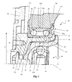
Figure 1 is an axial-symmetrical section of the hub-bearing assembly, according to a preferred embodiment of the present invention, -
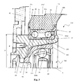
Figure 2 is an axial-symmetrical section of the hub-bearing assembly, showing a second embodiment of the invention, -
Figure 3 is an axial-symmetrical section of the hub-bearing assembly, showing a third embodiment of the invention. - With reference to
Figure 1 , a hub-bearing according to a first embodiment of the invention, is referenced as a whole with 10. - The
assembly 10 comprises ahub 20 and abearing unit 30. Throughout the present description and in the claims, the terms and expressions indicating positions and orientations such as "radial" and "axial" are to be taken to refer to the axis of rotation x of thebearing unit 30. Instead, expressions as "axially external" and "axially internal" are to be referred to the assembled condition, in this case respectively to a motor vehicle wheel side and to an opposite side. - The
bearing unit 30 comprises a radiallyouter ring 31, stationary, a pair of radiallyinner rings rolling elements outer ring 31 and theinner rings - The stationary
outer ring 31 has a tubularmain portion 31a axially extending, which internally defines theraceways 36 of therolling elements - The
outer ring 31 and in particular thetubular portion 31a has a radially externalcylindrical surface 31a' adapted to be coupled with acylindrical seat 41 formed in aknuckle 40 of a suspension. Thecylindrical surface 31a' extends for the entire axial dimension of theouter ring 31 and has an axial dimension of the order of magnitude of the dimension of the knucklecylindrical seat 41. The two axially opposite ends of thecylindrical surface 31a' are presented by respective axial opposite ends of thetubular projections tubular portion 31a. Thetubular projections tubular projection 31b is obtained by machining before the assembly of the radiallyouter ring 31 on theknuckle 40, thus realizing a shoulder for the knuckle. Thetubular projection 31c is obtained, after mounting the knuckle, by cold plastic forming (in particular, by riveting or other similar operation), so as to ensure the stable coupling between the knuckle and the radially outer ring. Alternatively, it is possible to perform machining to obtain thetubular projection 31c and plastic deformation to obtain thetubular projection 31b. - Preferably, the radially
inner rings knuckle 40. - The
rolling elements inner rings hub 20 shaped as a rotor and made of aluminum or other light alloy. - The
hub 20 has a centraltubular portion 21, which is steadily connected with a rollededge 22, axially internal, and an axiallyouter flange portion 23. The flange portion has a plurality ofaxial fixing holes 24 the axes of which are arranged along a circle of radius r, with respect to the symmetry axis X. The holes are seats for corresponding fastening means (such as stud bolts, not shown in the figure) that connect in a known way an element of the wheel of the motor vehicle, for example thebrake disc 50, to theflanged hub 20. - The
flanged hub 20, made of aluminum or other light alloy, is realized in such a way that its radial extension does not exceed the radius R of the circle comprising the centers of therolling elements mounting holes 24 is smaller than the radius R of the circle of the centers of therolling elements rolling elements 34, axially external and closest to the brake disc of the wheel of the motor vehicle. - Through this solution, the flanged hub assumes a shape as a rotor, in other words, its flange portion is very reduced and, in particular, does not radially extend beyond the diameter of the centers of the rolling elements. This allows to realize the
hub 20 in a light alloy, for example aluminum, although the hub itself can withstand the loads transmitted by the wheel of the motor vehicle. The above solution is obtained by increasing the radius R of the circle of the centers of the rolling elements and obviously not varying (since it is a constraint of the project of the motor vehicle) the radius r of the circle of the axes of thefixing holes 24. - The axial preload to the pair of
inner rings edge 22 of the hub. - The transmission of the motion from a drive shaft of the transmission unit of a motor vehicle (not shown) is guaranteed by the angular coupling of the
hub 20 with aconstant velocity joint 60. - Having increased the radius R of the circle of the centers of the rolling elements, the
constant velocity joint 60, and in particular its radially outer portion, or thebell 61, can be designed so as to be inserted in the space left free by the central rotor-hub. In this way, a very stiff unit is obtained, also compact in size and lightweight. Acentral screw element 70 ensures the axial connection between theconstant velocity joint 60 and thehub 20. In the configuration ofFig. 1 , thebell 61 has a preformed axiallyinner edge 62, configured to cooperate with the rollededge 22 of the hub, thus making the whole unit even more robust. - The torque transmission between the
constant velocity joint 60 and thehub 20 is realized by angularly coupling thebell 61 to thehub 20, by means of the knurled coupling between the radially outercylindrical surface 61a of the bell and the radially innercylindrical surface 21a of the hub. - In
Figure 2 is shown a second embodiment of the present invention, where the hub-bearing assembly is referred as 110. Compared to the previous embodiment, this embodiment differs in that thehub 120 is devoid of the axially inner rolled edge. Therefore, in this solution the axial preload to theinner rings preformed edge 162 of thebell 161 of theconstant velocity joint 160. Further aspects of this solution coincide with what has been described regarding the first embodiment. - In
Figure 3 , a third embodiment of the present invention is shown, where the hub bearing assembly is referred as 210. Compared to the solution ofFig. 1 , in the present embodiment there are two different aspects. A first difference is the fact that the axial preload to theinner rings edge 22 of thehub 220, as in the solution inFig. 1 , but in this case without the aid of the preformed edge of the bell. In fact, in the solution ofFig. 3 , thebell 261 of the constant velocity joint 260 is devoid of preformed axially inner edge. - A second difference, compared to the first embodiment is that the transmission of torque between the constant velocity joint 260 and the
hub 220 is accomplished by angularly coupling thebell 261 to thehub 220, by means of coupling between a radially outerconical surface 261a of the bell and a radially innerconical surface 221a of thetubular portion 221 of thehub 220. - Therefore, the solution created and declined in the presented embodiments allows to achieve a lightweight hub-bearing assembly, since only the bearing and the joint are made of steel while the hub is in light alloy. Moreover, the assembly has very limited axial dimensions, since the hub is almost devoid of flange portions and of the relative axial dimensions and the bell of the joint is positioned so as to be radially inside the bearing. As consequence of the increased radius of the centers of the rolling elements, a larger bearing diameter of the bearing also reduces the local loads between rings and rolling elements of the bearing. Finally, a larger diameter of the centers of the rolling elements of the bearing ensures greater resistance and durability.
- Other than the embodiments of the invention, as above disclosed, it is to be understood that a vast number of variations exist. It should also be appreciated that the exemplary embodiment or exemplary embodiments are only examples and are not intended to limit the scope, applicability, or configuration in any way. Rather, the foregoing summary and detailed description will provide those skilled in the art with a convenient road map for implementing at least one exemplary embodiment, it being understood that various changes may be made in the function and arrangement of elements described in an exemplary embodiment without departing from the scope as set forth in the appended claims and their legal equivalents.
Claims (8)
- A hub-bearing assembly (10, 110, 210) comprising:- a bearing unit (30) comprising a radially outer ring (31), stationary, a couple of radially inner rings (32, 33), rotatable, and a double row of rolling elements (34, 35), which are interposed between the radially outer ring and the radially inner rings, whose centers are located along a first circle having a radius (R), with respect to a symmetry axis (X) of the hub-bearing assembly (10, 110, 210),- a rotor-hub (20, 120, 220), rotatable and made of a light alloy, on top of which the radially inner rings (32, 33) are assembled, the rotor-hub comprising a tubular portion (21, 221), to which is steadily fixed a flange portion, axially external and provided with a plurality of fixing holes (24), whose axes are located along a second circle having a radius (r), with respect to the symmetry axis (X) of the hub-bearing assembly (10, 110, 210), and said fixing holes (24) are seat of corresponding fastening means, engaging a wheel component of a motor vehicle to the rotor-hub (20, 120, 220),
characterized in that- the radius (R) of the first circle of the rolling elements (34, 35) centers is greater than the radius (r) of the second circle of the fixing holes (24) axes. - Hub-bearing assembly according to claim 1, wherein the rotor-hub (20, 120, 220) e angularly coupled to a bell (61, 161, 261) of a constant velocity joint (60, 160, 260), from which the rotor-hub receives the driving torque and characterized in that the bell (61, 161, 261) is the radially outer portion of the constant velocity joint (60, 160, 260) and is co-axial and radially internal to rotor-hub (20, 120, 220).
- Hub-bearing assembly according to claim 2, characterized in that the rotor-hub (20, 120) and the bell (61, 161) are angularly coupled by means of a milled coupling between a radially external cylindrical surface (61a) of the bell (61, 161) and a radially internal cylindrical surface (21a) of the tubular portion (21) of the rotor-hub (20, 120).
- Hub-bearing assembly according to claim 2, characterized in that the rotor-hub (220) and the bell (261) are angularly coupled by means of a coupling between a radially external conical surface (261a) of the bell (261) and a radially internal conical surface (221a) of the tubular portion (221) of the rotor-hub (220).
- Hub-bearing assembly according to any of the preceding claims, characterized in that the tubular portion (21, 221) of the rotor-hub (20, 120, 220) is steadily fixed to a rolled edge (22), which is axially internal and configured to axially pre-load the couple of radially inner rings (32, 33).
- Hub-bearing assembly according to claim 5, characterized in that the bell (61) comprises a pre-formed edge (62), which is axially internal and configured to cooperate with the rolled edge (22) to axially pre-load the couple of radially inner rings (32, 33).
- Hub-bearing assembly according to any of the claims from 2 to 4, characterized in that the bell (161) comprises a pre-formed edge (162), which is axially internal and configured to to axially pre-load the couple of radially inner rings (32, 33).
- Hub-bearing assembly according to any of the preceding claims, characterized in that a tubular portion (31a) of the outer ring (31) comprises a cylindrical surface (31a'), which is radially external and configured to be coupled to a cylindrical seat (41) of a knuckle (40) of a vehicle suspension.
Applications Claiming Priority (1)
| Application Number | Priority Date | Filing Date | Title |
|---|---|---|---|
| ITTO20140495 | 2014-06-20 |
Publications (2)
| Publication Number | Publication Date |
|---|---|
| EP2957432A1 true EP2957432A1 (en) | 2015-12-23 |
| EP2957432B1 EP2957432B1 (en) | 2018-01-31 |
Family
ID=51454896
Family Applications (1)
| Application Number | Title | Priority Date | Filing Date |
|---|---|---|---|
| EP15172136.2A Active EP2957432B1 (en) | 2014-06-20 | 2015-06-15 | Hub-bearing having a light alloy rotor-hub |
Country Status (2)
| Country | Link |
|---|---|
| EP (1) | EP2957432B1 (en) |
| CN (1) | CN105202016B (en) |
Cited By (3)
| Publication number | Priority date | Publication date | Assignee | Title |
|---|---|---|---|---|
| DE102017116134A1 (en) * | 2017-07-18 | 2019-01-24 | Saf-Holland Gmbh | Wheel hub, a brake disc, a fastener and a system of wheel hub, brake disc and fasteners |
| CN109311344A (en) * | 2016-06-13 | 2019-02-05 | Ksm铸造集团有限公司 | wheel frame |
| KR20250035243A (en) * | 2023-09-05 | 2025-03-12 | 주식회사 일진글로벌 | Wheel hub bearing unit for vehicle |
Families Citing this family (3)
| Publication number | Priority date | Publication date | Assignee | Title |
|---|---|---|---|---|
| DE102018107774A1 (en) * | 2018-04-03 | 2019-10-10 | Schaeffler Technologies AG & Co. KG | Spherical bearing for a wheel module of a motor vehicle |
| FR3106636B1 (en) * | 2020-01-24 | 2022-01-14 | Ntn Snr Roulements | Motor vehicle wheel assembly |
| CN111981047A (en) * | 2020-09-07 | 2020-11-24 | 天津英创汇智汽车技术有限公司 | Axial limiting method for inner ring and outer ring of gear bearing of electronic brake booster unit |
Citations (7)
| Publication number | Priority date | Publication date | Assignee | Title |
|---|---|---|---|---|
| DE3400701A1 (en) | 1984-01-11 | 1985-07-18 | Bayerische Motoren Werke AG, 8000 München | Device for the attachment of a vehicle wheel to a rotatably mounted axle component |
| US5486053A (en) * | 1992-03-19 | 1996-01-23 | Skf Industrial Trading & Development Company B.V. | Bearing unit for a vehicle wheel |
| US5813938A (en) * | 1995-03-20 | 1998-09-29 | Linde Aktiengesellschaft | Wheel mounting hub system |
| DE10128073A1 (en) * | 2001-06-09 | 2002-12-12 | Daimler Chrysler Ag | Bearing for driven rigid axle comprises drive shaft mounted in roller bearing, wheel flange and brake disk being releasably fastened to flange on outer ring |
| WO2005030499A1 (en) | 2003-09-30 | 2005-04-07 | Skf Research & Development Company B.V. | Mechanical system with moveable parts equipped with monitoring device |
| EP1031439B1 (en) | 1999-02-24 | 2005-04-27 | Skf Industrie S.P.A. | A motor vehicle wheel hub bearing and a method for mounting the bearing onto a motor vehicle suspension |
| DE102008051601A1 (en) * | 2008-10-14 | 2010-06-10 | Daimler Ag | Device for fastening vehicle rim to wheel hub of lorry, is designed such vehicle rim is fastened to brake disk in force-fit and/or form-fit manner by screw nuts arranged on threaded section of stud screw |
Family Cites Families (2)
| Publication number | Priority date | Publication date | Assignee | Title |
|---|---|---|---|---|
| EP1666744A1 (en) * | 2004-12-06 | 2006-06-07 | Ab Skf | Bearing unit comprising a sheet metal element |
| JP5829173B2 (en) * | 2012-04-27 | 2015-12-09 | Ntn株式会社 | Manufacturing method of wheel bearing device |
-
2015
- 2015-06-15 EP EP15172136.2A patent/EP2957432B1/en active Active
- 2015-06-19 CN CN201510571446.4A patent/CN105202016B/en active Active
Patent Citations (7)
| Publication number | Priority date | Publication date | Assignee | Title |
|---|---|---|---|---|
| DE3400701A1 (en) | 1984-01-11 | 1985-07-18 | Bayerische Motoren Werke AG, 8000 München | Device for the attachment of a vehicle wheel to a rotatably mounted axle component |
| US5486053A (en) * | 1992-03-19 | 1996-01-23 | Skf Industrial Trading & Development Company B.V. | Bearing unit for a vehicle wheel |
| US5813938A (en) * | 1995-03-20 | 1998-09-29 | Linde Aktiengesellschaft | Wheel mounting hub system |
| EP1031439B1 (en) | 1999-02-24 | 2005-04-27 | Skf Industrie S.P.A. | A motor vehicle wheel hub bearing and a method for mounting the bearing onto a motor vehicle suspension |
| DE10128073A1 (en) * | 2001-06-09 | 2002-12-12 | Daimler Chrysler Ag | Bearing for driven rigid axle comprises drive shaft mounted in roller bearing, wheel flange and brake disk being releasably fastened to flange on outer ring |
| WO2005030499A1 (en) | 2003-09-30 | 2005-04-07 | Skf Research & Development Company B.V. | Mechanical system with moveable parts equipped with monitoring device |
| DE102008051601A1 (en) * | 2008-10-14 | 2010-06-10 | Daimler Ag | Device for fastening vehicle rim to wheel hub of lorry, is designed such vehicle rim is fastened to brake disk in force-fit and/or form-fit manner by screw nuts arranged on threaded section of stud screw |
Cited By (5)
| Publication number | Priority date | Publication date | Assignee | Title |
|---|---|---|---|---|
| CN109311344A (en) * | 2016-06-13 | 2019-02-05 | Ksm铸造集团有限公司 | wheel frame |
| DE102017116134A1 (en) * | 2017-07-18 | 2019-01-24 | Saf-Holland Gmbh | Wheel hub, a brake disc, a fastener and a system of wheel hub, brake disc and fasteners |
| DE102017116134B4 (en) | 2017-07-18 | 2021-08-12 | Saf-Holland Gmbh | Wheel hub, a brake disk, a fastening means and a system comprising a wheel hub, brake disk and fastening means |
| US11590796B2 (en) | 2017-07-18 | 2023-02-28 | Saf-Holland Gmbh | Wheel hub, a brake disc, a fastening means, and a system formed of wheel hub, brake disc and fastening means |
| KR20250035243A (en) * | 2023-09-05 | 2025-03-12 | 주식회사 일진글로벌 | Wheel hub bearing unit for vehicle |
Also Published As
| Publication number | Publication date |
|---|---|
| CN105202016A (en) | 2015-12-30 |
| CN105202016B (en) | 2019-06-07 |
| EP2957432B1 (en) | 2018-01-31 |
Similar Documents
| Publication | Publication Date | Title |
|---|---|---|
| EP2957432B1 (en) | Hub-bearing having a light alloy rotor-hub | |
| US9903417B2 (en) | Assembly procedure of a bearing unit—HUB flange | |
| EP2965922B1 (en) | Flanged hub-bearing unit | |
| EP1586794A2 (en) | Differential with pinion bearings supported on input yoke | |
| EP2602123B1 (en) | An integrated hub-bearing assembly for the wheel of a motor vehicle | |
| US6719661B2 (en) | Differential with pinion bearings supported on input yoke | |
| US9694627B2 (en) | Hub-bearing having a light alloy rotor-hub | |
| US9897138B2 (en) | Method for preloading a hub bearing unit | |
| CN101112867A (en) | Hub/universal joint assembly with retaining ring axially supporting clamping device | |
| CN115003925A (en) | Wheel assembly for motor vehicle | |
| CN107264184A (en) | Hub-bearing unit with rotor hub | |
| US7699405B2 (en) | Vehicle wheel end assemblies and methods of assembly thereof | |
| US7175349B2 (en) | Wheel rotation supporting apparatus | |
| EP2432650B1 (en) | Wheel bearing unit and method for producing the same | |
| US20080252030A1 (en) | Vehicle corner module | |
| JP2008173995A (en) | Bearing device for wheel | |
| EP2871067A1 (en) | Bearing-hub assembly with a light alloy hub | |
| EP2623334B1 (en) | Wheel support device | |
| EP2327568B1 (en) | A hub bearing-hub carrier unit for high-performance motor vehicles | |
| JP2018197598A (en) | Drive wheel hub unit | |
| JP2004106618A (en) | Rolling bearing unit for wheel support | |
| KR20200120562A (en) | Wheel bearing assembly | |
| JP4846672B2 (en) | Axle bearing and wheel bearing device | |
| JP2006096143A (en) | Hub unit for vehicles | |
| CN118386727A (en) | Motor vehicle wheel assembly |
Legal Events
| Date | Code | Title | Description |
|---|---|---|---|
| PUAI | Public reference made under article 153(3) epc to a published international application that has entered the european phase |
Free format text: ORIGINAL CODE: 0009012 |
|
| AK | Designated contracting states |
Kind code of ref document: A1 Designated state(s): AL AT BE BG CH CY CZ DE DK EE ES FI FR GB GR HR HU IE IS IT LI LT LU LV MC MK MT NL NO PL PT RO RS SE SI SK SM TR |
|
| AX | Request for extension of the european patent |
Extension state: BA ME |
|
| 17P | Request for examination filed |
Effective date: 20160615 |
|
| RBV | Designated contracting states (corrected) |
Designated state(s): AL AT BE BG CH CY CZ DE DK EE ES FI FR GB GR HR HU IE IS IT LI LT LU LV MC MK MT NL NO PL PT RO RS SE SI SK SM TR |
|
| GRAP | Despatch of communication of intention to grant a patent |
Free format text: ORIGINAL CODE: EPIDOSNIGR1 |
|
| STAA | Information on the status of an ep patent application or granted ep patent |
Free format text: STATUS: GRANT OF PATENT IS INTENDED |
|
| INTG | Intention to grant announced |
Effective date: 20170828 |
|
| GRAS | Grant fee paid |
Free format text: ORIGINAL CODE: EPIDOSNIGR3 |
|
| GRAA | (expected) grant |
Free format text: ORIGINAL CODE: 0009210 |
|
| STAA | Information on the status of an ep patent application or granted ep patent |
Free format text: STATUS: THE PATENT HAS BEEN GRANTED |
|
| AK | Designated contracting states |
Kind code of ref document: B1 Designated state(s): AL AT BE BG CH CY CZ DE DK EE ES FI FR GB GR HR HU IE IS IT LI LT LU LV MC MK MT NL NO PL PT RO RS SE SI SK SM TR |
|
| REG | Reference to a national code |
Ref country code: GB Ref legal event code: FG4D Ref country code: CH Ref legal event code: EP |
|
| REG | Reference to a national code |
Ref country code: AT Ref legal event code: REF Ref document number: 966993 Country of ref document: AT Kind code of ref document: T Effective date: 20180215 |
|
| REG | Reference to a national code |
Ref country code: IE Ref legal event code: FG4D |
|
| REG | Reference to a national code |
Ref country code: DE Ref legal event code: R096 Ref document number: 602015007685 Country of ref document: DE |
|
| REG | Reference to a national code |
Ref country code: NL Ref legal event code: MP Effective date: 20180131 |
|
| REG | Reference to a national code |
Ref country code: LT Ref legal event code: MG4D |
|
| REG | Reference to a national code |
Ref country code: AT Ref legal event code: MK05 Ref document number: 966993 Country of ref document: AT Kind code of ref document: T Effective date: 20180131 |
|
| PG25 | Lapsed in a contracting state [announced via postgrant information from national office to epo] |
Ref country code: NO Free format text: LAPSE BECAUSE OF FAILURE TO SUBMIT A TRANSLATION OF THE DESCRIPTION OR TO PAY THE FEE WITHIN THE PRESCRIBED TIME-LIMIT Effective date: 20180430 Ref country code: LT Free format text: LAPSE BECAUSE OF FAILURE TO SUBMIT A TRANSLATION OF THE DESCRIPTION OR TO PAY THE FEE WITHIN THE PRESCRIBED TIME-LIMIT Effective date: 20180131 Ref country code: HR Free format text: LAPSE BECAUSE OF FAILURE TO SUBMIT A TRANSLATION OF THE DESCRIPTION OR TO PAY THE FEE WITHIN THE PRESCRIBED TIME-LIMIT Effective date: 20180131 Ref country code: NL Free format text: LAPSE BECAUSE OF FAILURE TO SUBMIT A TRANSLATION OF THE DESCRIPTION OR TO PAY THE FEE WITHIN THE PRESCRIBED TIME-LIMIT Effective date: 20180131 Ref country code: ES Free format text: LAPSE BECAUSE OF FAILURE TO SUBMIT A TRANSLATION OF THE DESCRIPTION OR TO PAY THE FEE WITHIN THE PRESCRIBED TIME-LIMIT Effective date: 20180131 Ref country code: FI Free format text: LAPSE BECAUSE OF FAILURE TO SUBMIT A TRANSLATION OF THE DESCRIPTION OR TO PAY THE FEE WITHIN THE PRESCRIBED TIME-LIMIT Effective date: 20180131 |
|
| PG25 | Lapsed in a contracting state [announced via postgrant information from national office to epo] |
Ref country code: SE Free format text: LAPSE BECAUSE OF FAILURE TO SUBMIT A TRANSLATION OF THE DESCRIPTION OR TO PAY THE FEE WITHIN THE PRESCRIBED TIME-LIMIT Effective date: 20180131 Ref country code: LV Free format text: LAPSE BECAUSE OF FAILURE TO SUBMIT A TRANSLATION OF THE DESCRIPTION OR TO PAY THE FEE WITHIN THE PRESCRIBED TIME-LIMIT Effective date: 20180131 Ref country code: BG Free format text: LAPSE BECAUSE OF FAILURE TO SUBMIT A TRANSLATION OF THE DESCRIPTION OR TO PAY THE FEE WITHIN THE PRESCRIBED TIME-LIMIT Effective date: 20180430 Ref country code: PL Free format text: LAPSE BECAUSE OF FAILURE TO SUBMIT A TRANSLATION OF THE DESCRIPTION OR TO PAY THE FEE WITHIN THE PRESCRIBED TIME-LIMIT Effective date: 20180131 Ref country code: GR Free format text: LAPSE BECAUSE OF FAILURE TO SUBMIT A TRANSLATION OF THE DESCRIPTION OR TO PAY THE FEE WITHIN THE PRESCRIBED TIME-LIMIT Effective date: 20180501 Ref country code: IS Free format text: LAPSE BECAUSE OF FAILURE TO SUBMIT A TRANSLATION OF THE DESCRIPTION OR TO PAY THE FEE WITHIN THE PRESCRIBED TIME-LIMIT Effective date: 20180531 Ref country code: AT Free format text: LAPSE BECAUSE OF FAILURE TO SUBMIT A TRANSLATION OF THE DESCRIPTION OR TO PAY THE FEE WITHIN THE PRESCRIBED TIME-LIMIT Effective date: 20180131 Ref country code: RS Free format text: LAPSE BECAUSE OF FAILURE TO SUBMIT A TRANSLATION OF THE DESCRIPTION OR TO PAY THE FEE WITHIN THE PRESCRIBED TIME-LIMIT Effective date: 20180131 |
|
| PG25 | Lapsed in a contracting state [announced via postgrant information from national office to epo] |
Ref country code: IT Free format text: LAPSE BECAUSE OF FAILURE TO SUBMIT A TRANSLATION OF THE DESCRIPTION OR TO PAY THE FEE WITHIN THE PRESCRIBED TIME-LIMIT Effective date: 20180131 Ref country code: AL Free format text: LAPSE BECAUSE OF FAILURE TO SUBMIT A TRANSLATION OF THE DESCRIPTION OR TO PAY THE FEE WITHIN THE PRESCRIBED TIME-LIMIT Effective date: 20180131 Ref country code: EE Free format text: LAPSE BECAUSE OF FAILURE TO SUBMIT A TRANSLATION OF THE DESCRIPTION OR TO PAY THE FEE WITHIN THE PRESCRIBED TIME-LIMIT Effective date: 20180131 Ref country code: RO Free format text: LAPSE BECAUSE OF FAILURE TO SUBMIT A TRANSLATION OF THE DESCRIPTION OR TO PAY THE FEE WITHIN THE PRESCRIBED TIME-LIMIT Effective date: 20180131 |
|
| REG | Reference to a national code |
Ref country code: DE Ref legal event code: R097 Ref document number: 602015007685 Country of ref document: DE |
|
| PG25 | Lapsed in a contracting state [announced via postgrant information from national office to epo] |
Ref country code: SM Free format text: LAPSE BECAUSE OF FAILURE TO SUBMIT A TRANSLATION OF THE DESCRIPTION OR TO PAY THE FEE WITHIN THE PRESCRIBED TIME-LIMIT Effective date: 20180131 Ref country code: DK Free format text: LAPSE BECAUSE OF FAILURE TO SUBMIT A TRANSLATION OF THE DESCRIPTION OR TO PAY THE FEE WITHIN THE PRESCRIBED TIME-LIMIT Effective date: 20180131 Ref country code: CZ Free format text: LAPSE BECAUSE OF FAILURE TO SUBMIT A TRANSLATION OF THE DESCRIPTION OR TO PAY THE FEE WITHIN THE PRESCRIBED TIME-LIMIT Effective date: 20180131 Ref country code: SK Free format text: LAPSE BECAUSE OF FAILURE TO SUBMIT A TRANSLATION OF THE DESCRIPTION OR TO PAY THE FEE WITHIN THE PRESCRIBED TIME-LIMIT Effective date: 20180131 |
|
| PLBE | No opposition filed within time limit |
Free format text: ORIGINAL CODE: 0009261 |
|
| STAA | Information on the status of an ep patent application or granted ep patent |
Free format text: STATUS: NO OPPOSITION FILED WITHIN TIME LIMIT |
|
| 26N | No opposition filed |
Effective date: 20181102 |
|
| REG | Reference to a national code |
Ref country code: CH Ref legal event code: PL |
|
| PG25 | Lapsed in a contracting state [announced via postgrant information from national office to epo] |
Ref country code: SI Free format text: LAPSE BECAUSE OF FAILURE TO SUBMIT A TRANSLATION OF THE DESCRIPTION OR TO PAY THE FEE WITHIN THE PRESCRIBED TIME-LIMIT Effective date: 20180131 |
|
| REG | Reference to a national code |
Ref country code: BE Ref legal event code: MM Effective date: 20180630 |
|
| REG | Reference to a national code |
Ref country code: IE Ref legal event code: MM4A |
|
| PG25 | Lapsed in a contracting state [announced via postgrant information from national office to epo] |
Ref country code: LU Free format text: LAPSE BECAUSE OF NON-PAYMENT OF DUE FEES Effective date: 20180615 Ref country code: MC Free format text: LAPSE BECAUSE OF FAILURE TO SUBMIT A TRANSLATION OF THE DESCRIPTION OR TO PAY THE FEE WITHIN THE PRESCRIBED TIME-LIMIT Effective date: 20180131 |
|
| PG25 | Lapsed in a contracting state [announced via postgrant information from national office to epo] |
Ref country code: LI Free format text: LAPSE BECAUSE OF NON-PAYMENT OF DUE FEES Effective date: 20180630 Ref country code: CH Free format text: LAPSE BECAUSE OF NON-PAYMENT OF DUE FEES Effective date: 20180630 Ref country code: FR Free format text: LAPSE BECAUSE OF NON-PAYMENT OF DUE FEES Effective date: 20180630 Ref country code: IE Free format text: LAPSE BECAUSE OF NON-PAYMENT OF DUE FEES Effective date: 20180615 |
|
| PG25 | Lapsed in a contracting state [announced via postgrant information from national office to epo] |
Ref country code: BE Free format text: LAPSE BECAUSE OF NON-PAYMENT OF DUE FEES Effective date: 20180630 |
|
| PG25 | Lapsed in a contracting state [announced via postgrant information from national office to epo] |
Ref country code: MT Free format text: LAPSE BECAUSE OF NON-PAYMENT OF DUE FEES Effective date: 20180615 |
|
| GBPC | Gb: european patent ceased through non-payment of renewal fee |
Effective date: 20190615 |
|
| PG25 | Lapsed in a contracting state [announced via postgrant information from national office to epo] |
Ref country code: TR Free format text: LAPSE BECAUSE OF FAILURE TO SUBMIT A TRANSLATION OF THE DESCRIPTION OR TO PAY THE FEE WITHIN THE PRESCRIBED TIME-LIMIT Effective date: 20180131 |
|
| PG25 | Lapsed in a contracting state [announced via postgrant information from national office to epo] |
Ref country code: GB Free format text: LAPSE BECAUSE OF NON-PAYMENT OF DUE FEES Effective date: 20190615 |
|
| PG25 | Lapsed in a contracting state [announced via postgrant information from national office to epo] |
Ref country code: PT Free format text: LAPSE BECAUSE OF FAILURE TO SUBMIT A TRANSLATION OF THE DESCRIPTION OR TO PAY THE FEE WITHIN THE PRESCRIBED TIME-LIMIT Effective date: 20180131 |
|
| PG25 | Lapsed in a contracting state [announced via postgrant information from national office to epo] |
Ref country code: CY Free format text: LAPSE BECAUSE OF FAILURE TO SUBMIT A TRANSLATION OF THE DESCRIPTION OR TO PAY THE FEE WITHIN THE PRESCRIBED TIME-LIMIT Effective date: 20180131 Ref country code: HU Free format text: LAPSE BECAUSE OF FAILURE TO SUBMIT A TRANSLATION OF THE DESCRIPTION OR TO PAY THE FEE WITHIN THE PRESCRIBED TIME-LIMIT; INVALID AB INITIO Effective date: 20150615 Ref country code: MK Free format text: LAPSE BECAUSE OF NON-PAYMENT OF DUE FEES Effective date: 20180131 |
|
| P01 | Opt-out of the competence of the unified patent court (upc) registered |
Effective date: 20230513 |
|
| REG | Reference to a national code |
Ref country code: DE Ref legal event code: R082 Ref document number: 602015007685 Country of ref document: DE Representative=s name: SCHONECKE, MITJA, DIPL.-PHYS. DR. RER. NAT., DE Ref country code: DE Ref legal event code: R082 Ref document number: 602015007685 Country of ref document: DE Representative=s name: SCHONECKE, MITJA, DR., DE |
|
| REG | Reference to a national code |
Ref country code: DE Ref legal event code: R082 Ref document number: 602015007685 Country of ref document: DE Representative=s name: SCHONECKE, MITJA, DR., DE |
|
| PGFP | Annual fee paid to national office [announced via postgrant information from national office to epo] |
Ref country code: DE Payment date: 20260623 Year of fee payment: 12 |