EP2957310A1 - Gasket to be used for medical syringe, and medical syringe - Google Patents
Gasket to be used for medical syringe, and medical syringe Download PDFInfo
- Publication number
- EP2957310A1 EP2957310A1 EP15165532.1A EP15165532A EP2957310A1 EP 2957310 A1 EP2957310 A1 EP 2957310A1 EP 15165532 A EP15165532 A EP 15165532A EP 2957310 A1 EP2957310 A1 EP 2957310A1
- Authority
- EP
- European Patent Office
- Prior art keywords
- gasket
- projection
- syringe barrel
- peak
- syringe
- Prior art date
- Legal status (The legal status is an assumption and is not a legal conclusion. Google has not performed a legal analysis and makes no representation as to the accuracy of the status listed.)
- Granted
Links
Images


Classifications
-
- A—HUMAN NECESSITIES
- A61—MEDICAL OR VETERINARY SCIENCE; HYGIENE
- A61M—DEVICES FOR INTRODUCING MEDIA INTO, OR ONTO, THE BODY; DEVICES FOR TRANSDUCING BODY MEDIA OR FOR TAKING MEDIA FROM THE BODY; DEVICES FOR PRODUCING OR ENDING SLEEP OR STUPOR
- A61M5/00—Devices for bringing media into the body in a subcutaneous, intra-vascular or intramuscular way; Accessories therefor, e.g. filling or cleaning devices, arm-rests
- A61M5/178—Syringes
- A61M5/31—Details
- A61M5/315—Pistons; Piston-rods; Guiding, blocking or restricting the movement of the rod or piston; Appliances on the rod for facilitating dosing ; Dosing mechanisms
- A61M5/31511—Piston or piston-rod constructions, e.g. connection of piston with piston-rod
- A61M5/31513—Piston constructions to improve sealing or sliding
-
- A—HUMAN NECESSITIES
- A61—MEDICAL OR VETERINARY SCIENCE; HYGIENE
- A61M—DEVICES FOR INTRODUCING MEDIA INTO, OR ONTO, THE BODY; DEVICES FOR TRANSDUCING BODY MEDIA OR FOR TAKING MEDIA FROM THE BODY; DEVICES FOR PRODUCING OR ENDING SLEEP OR STUPOR
- A61M5/00—Devices for bringing media into the body in a subcutaneous, intra-vascular or intramuscular way; Accessories therefor, e.g. filling or cleaning devices, arm-rests
- A61M5/178—Syringes
- A61M5/31—Details
- A61M5/315—Pistons; Piston-rods; Guiding, blocking or restricting the movement of the rod or piston; Appliances on the rod for facilitating dosing ; Dosing mechanisms
- A61M5/31501—Means for blocking or restricting the movement of the rod or piston
-
- F—MECHANICAL ENGINEERING; LIGHTING; HEATING; WEAPONS; BLASTING
- F16—ENGINEERING ELEMENTS AND UNITS; GENERAL MEASURES FOR PRODUCING AND MAINTAINING EFFECTIVE FUNCTIONING OF MACHINES OR INSTALLATIONS; THERMAL INSULATION IN GENERAL
- F16J—PISTONS; CYLINDERS; SEALINGS
- F16J15/00—Sealings
-
- A—HUMAN NECESSITIES
- A61—MEDICAL OR VETERINARY SCIENCE; HYGIENE
- A61M—DEVICES FOR INTRODUCING MEDIA INTO, OR ONTO, THE BODY; DEVICES FOR TRANSDUCING BODY MEDIA OR FOR TAKING MEDIA FROM THE BODY; DEVICES FOR PRODUCING OR ENDING SLEEP OR STUPOR
- A61M2205/00—General characteristics of the apparatus
- A61M2205/02—General characteristics of the apparatus characterised by a particular materials
- A61M2205/0222—Materials for reducing friction
-
- A—HUMAN NECESSITIES
- A61—MEDICAL OR VETERINARY SCIENCE; HYGIENE
- A61M—DEVICES FOR INTRODUCING MEDIA INTO, OR ONTO, THE BODY; DEVICES FOR TRANSDUCING BODY MEDIA OR FOR TAKING MEDIA FROM THE BODY; DEVICES FOR PRODUCING OR ENDING SLEEP OR STUPOR
- A61M2205/00—General characteristics of the apparatus
- A61M2205/02—General characteristics of the apparatus characterised by a particular materials
- A61M2205/0238—General characteristics of the apparatus characterised by a particular materials the material being a coating or protective layer
Definitions
- the present invention relates to a gasket to be used for a medical syringe, and a medical syringe.
- Syringes for use in medical applications typically include a syringe barrel, a plunger reciprocally movable in the syringe barrel, and a gasket attached to a distal end of the plunger.
- the gasket to be used for the syringes is required to have gas tightness and low-friction slidability.
- the gas tightness means that liquid drug is prevented from leaking outside during use and foreign matter is prevented from intruding from the outside.
- the low-friction slidability means that, when the syringe is used, a user can properly move the gasket by manipulating the plunger by one hand.
- the prior-art syringes ensure the low-friction slidability and the gas tightness with a silicone oil applied in the syringe barrel, but some liquid drugs are adversely influenced by the silicone. Therefore, it is desirable not to apply the silicone to the syringe barrel.
- a product called laminated gasket which includes a rubber gasket body having a surface laminated with a film having excellent slidability (e.g., a gasket laminated with a fluororesin film).
- a maximum diameter portion (peak portion) of the gasket When the laminated gasket is inserted in the syringe barrel, a maximum diameter portion (peak portion) of the gasket receives a counter force from an inner surface of the syringe barrel to shrink and, therefore, a portion of the fluororesin film of the maximum diameter portion is liable to be wrinkled or slacked. At this time, a gap is formed between the wrinkled or slacked peak portion of the gasket and the inner surface of the syringe barrel. This may reduce the gas tightness of the gasket, thereby causing the liquid leakage and the intrusion of foreign matter.
- a distal portion of the gasket has a curvature radius R of not greater than 0.1 mm in peripheral section to increase the gas tightness, and a portion of the gasket opposite from a liquid contact portion has a reduced peripheral radius to improve the slidability.
- the distal portion of the gasket has an excessively small curvature radius R in peripheral section, however, the lamination film is more liable to be torn. Further, the gasket is more liable to be inclined in various steps of the gasket production process.
- the distal portion of the gasket has a curvature radius of not less than 0.7 mm in peripheral section, so that the gas tightness can be ensured even if the gasket is inclined. If the distal portion has an increased curvature radius R in peripheral section, however, the slidability is improved but the gas tightness is disadvantageously reduced.
- a gasket to be used for a medial syringe including: a rubber body having a liquid contact portion and a sliding portion to be brought into contact with an inner surface of a syringe barrel; and a lamination film provided on a surface of the rubber body; wherein the sliding portion includes at least a first annular projection, an annular recess and a second annular projection arranged in this order in a direction rearward from a distal portion of the gasket serving as the liquid contact portion; wherein the first projection is designed so that a first peak appears adjacent the distal portion of the gasket when the gasket is fitted in the syringe barrel and a product ⁇ of a contact pressure P1f and a width D1f of the first peak is 0.4 ⁇ ⁇ ⁇ 1.0 as determined by an FEM analysis.
- the lamination film is made of PTFE in the gasket of claim 1.
- two peaks including a distal peak and a rear side peak appear on the first projection of the gasket of claim 1.
- a product ⁇ of a contact pressure P2 and a width D2 for the second projection of the gasket of claim 1 is 0.2 ⁇ ⁇ ⁇ 0.6 as determined by the FEM analysis.
- an edge portion of the first projection adjacent to the distal portion has a curvature radius of not greater than 1.2 mm in the gasket of claim 1.
- a medical syringe which includes a tubular syringe barrel, a plunger combined with the syringe barrel and movable in the syringe barrel, and a gasket of claim 1 attached to a distal end of the plunger.
- the gas tightness and the low-friction slidability required for the gasket are related with the contact pressure at which the gasket presses the syringe barrel. That is, when an FEM (finite element method) analysis was performed with the gasket inserted in the syringe barrel, it was found that the gas tightness and the low-friction slidability were influenced by the contact pressure at which the gasket presses the syringe barrel.
- the gas tightness is significantly influenced by the contact pressure of the projection (first projection) adjacent to the distal portion of the gasket. Particularly, it was found that the product of the contact pressure (P1f) and the width (axial width D1f) of the peak appearing on the distal side of the first projection is a very important factor for the gas tightness.
- the sliding portion preferably includes the first projection as well as the annular second projection arranged in this order in the direction rearward from the distal portion for smooth sliding and capping.
- the first projection is desirably configured so as to have a double-peak contact pressure profile as determined by the FEM analysis.
- the gasket has an improved gas tightness and, in addition, the gas tightness can be ensured even if the gasket is inclined during the handling.
- the gasket has an improved gas tightness and, hence, improves the liquid drug storage stability when being used for a prefilled syringe.
- gas tightness and the slidability of the gasket can be estimated by the FEM analysis in the gasket production process, so that a safer gasket can be designed in a shorter period of time.
- FIG. 1 is an exploded diagram illustrating a medical syringe, i.e., a so-called prefilled syringe, according to the embodiment of the present invention.
- a medical syringe i.e., a so-called prefilled syringe
- FIG. 1 a half of a syringe barrel 11 and a half of a gasket 13 are illustrated in section.
- the prefilled syringe 10 includes a hollow cylindrical syringe barrel 11, a plunger 12 combined with the syringe barrel 11 and reciprocally movable in the syringe barrel 11, and a gasket 13 attached to a distal end of the plunger 12.
- the gasket 13 is a so-called laminated gasket, which includes a main body 14 made of an elastic material (a rubber or an elastomer) and a lamination film 15 provided on a surface of the main body 14.
- the gasket 13 includes two circumferential portions, i.e., a first projection 17A and a second projection 17B, serving as a sliding portion to be kept in gas-tight and liquid-tight contact with an inner peripheral surface 16 of the syringe barrel 11.
- the plunger 12 includes a resin plate piece, for example, having a cross shape as seen in section, and a head 18 provided at a distal end of the resin plate piece and fitted with the gasket 13.
- the head 18 is an integral part of the plunger 12 made of a resin and shaped in a male screw.
- the gasket 13 has a generally cylindrical shape having a short axis.
- the gasket 13 has a distal end face, for example, having a conical center portion projecting at an obtuse angle, and a rear end face axially recessed into an engagement recess 21 shaped in a female screw.
- the head 18 of the plunger 12 is screwed into the engagement recess 21 of the gasket 13, whereby the gasket 13 is attached to the distal end of the plunger 12.
- FIG. 2 is a diagram showing only the gasket 13 of FIG. 1 on an enlarged scale. In FIG. 2 , a half of the gasket 13 is illustrated in section.
- the gasket 13 includes the main body 14, and the lamination film 15 provided on the surface of the main body 14.
- the main body 14 is made of an elastomeric rubber (crosslinked rubber).
- the type of the lamination film 15 provided on the surface of the main body 14 is not particularly limited, as long as the lamination film 15 can prevent migration of components from the crosslinked rubber (main body 14) and is more excellent in slidability than the rubber, i.e., has a smaller friction coefficient than the rubber.
- Exemplary materials for the main body 14 and the lamination film 15 are shown below.
- Examples of the rubber to be used as the material for the main body 14 include butyl rubbers, isoprene rubbers, butadiene rubbers, styrene-butadiene rubbers, natural rubbers, chloroprene rubbers, nitrile rubbers such as acrylonitrile-butadiene rubbers, hydrogenated nitrile rubbers, norbornene rubbers, ethylene-propylene rubbers, ethylene-propylene-diene rubbers, acryl rubbers, ethylene-acrylate rubbers, fluororubbers, chlorosulfonated polyethylene rubbers, epichlorohydrin rubbers, silicone rubbers, urethane rubbers, polysulfide rubbers, phosphazene rubbers and 1,2-polybutadiene rubbers.
- butyl rubbers isoprene rubbers, butadiene rubbers, styrene-butadiene rubbers, natural rubbers, chloroprene rubbers, nitrile rubbers
- These rubbers may be used either alone or in combination.
- the rubber to be used for the main body 14 is not limited to the aforementioned rubbers, but is preferably a butyl rubber and/or an ethylene-propylene-diene rubber (hereinafter referred to as EPDM rubber).
- the butyl rubber is preferred because of its excellent gas permeation resistance and water vapor permeation resistance.
- a known butyl rubber compound may be used as the butyl rubber, but other examples of the butyl rubber include isobutylene-isoprene copolymer rubbers, halogenated isobutylene-isoprene copolymer rubbers (hereinafter referred to as halogenated butyl rubbers), and modification products of any of these rubbers.
- the modification products include bromination products of copolymers of isobutylene and p-methylstyrene.
- the halogenated butyl rubbers are more preferred, and chlorinated butyl rubbers and brominated butyl rubbers are further more preferred for easy crosslinking.
- the EPDM rubber is preferred because of its excellent processability.
- the EPDM rubber includes a non-oil extension type EPDM rubber containing only a rubber component and an oil extension type EPDM rubber containing a rubber component and an extension oil. In the present invention, either type of the EPDM rubbers may be used.
- Examples of a diene monomer for the EPDM rubber include dicyclopentadiene, methylene norbornene, ethylidene norbornene, 1,4-hexadiene and cyclooctadiene.
- halogenated butyl rubber and the EPDM rubber are advantageously used in combination because the resulting rubber is excellent in gas permeation resistance, water vapor permeation resistance and processability.
- the main body 14 is of the syringe gasket as a medical rubber product and, therefore, a butyl rubber having a lower gas permeability is preferably used as a principal rubber component.
- a triazine derivative crosslinking agent is preferably used as a crosslinking agent for cleanliness.
- the lamination film 15 is not particularly limited, but may be an inert film. At least one fluororesin selected from the group consisting of a polytetrafluoroethylene (PTFE), a modified polytetrafluoroethylene (modified PTFE, which is a copolymer of a 4F-monomer and a very small amount of a perfluoroalkoxide), a tetrafluoroethylene ethylene copolymer (ETFE), a tetrafluoroethylene perfluoroalkyl vinyl ether copolymer (PFA) and a polychlorotetrafluoroethylene (PCTFE), and/or an olefin resin are preferred for the lamination film 15 to provide excellent chemical resistance.
- PTFE polytetrafluoroethylene
- modified PTFE modified polytetrafluoroethylene
- EFE tetrafluoroethylene ethylene copolymer
- PFA tetrafluoroethylene perfluoroal
- the laminated gasket 13 according to this embodiment is produced by kneading ingredients blended in a predetermined blend radio by means of a sealed kneader, an open roll kneader or the like, forming the resulting kneaded product into an unvulcanized rubber sheet by means of a calender or a sheet forming machine, placing the unvulcanized rubber sheet and the inert film each having a predetermined weight and size in superposition in a die, and press-forming the unvulcanized rubber sheet and the inert film into a laminated gasket sheet by means of a vacuum press.
- the forming temperature is preferably 155°C to 200°C, more preferably 165°C to 180°C.
- the forming period is preferably 1 to 20 minutes, more preferably 3 to 15 minutes, further more preferably 5 to 10 minutes.
- the die to be used for the forming preferably has a sliding surface forming portion having a smooth die surface mirror-finished so as to have an arithmetic average roughness Ra of not greater than 0.03 ⁇ m as measured with a cutoff value of 0.08 mm. With the use of this die, the laminated rubber member thus formed can have a surface roughness smaller than the original surface roughness of the inert film.
- the arithmetic average roughness Ra is preferably not greater than 0.02 ⁇ m, more preferably not greater than 0.015 ⁇ m.
- a feature of the gasket 13 according to this embodiment is that the gasket 13 includes the first projection 17A and the second projection 17B serving as the sliding portion to be kept in gas-tight and liquid-tight contact with the inner peripheral surface 16 of the syringe barrel 11, and that the first projection 17A is designed so that a product of a contact pressure P1f and a width D1f is 0.4 ⁇ ⁇ ⁇ 1.0 as determined by an FEM analysis.
- the first projection 17A is designed so that two peaks including a distal peak and a rear side peak appear and a product of a contact pressure P1f and a width D1f of the distal peak is 0.4 ⁇ ⁇ ⁇ 1.0.
- the first projection 17A has a distal edge portion having a curvature radius R of not greater than 1.2 mm.
- the gasket 13 of this embodiment ensures the gas tightness and the low-friction slidability.
- An FEM (Finite Element Method) analysis was performed on gaskets each having a shape as shown in FIG. 2 , i.e., gaskets each having a sliding portion including a first projection 17A and a second projection 17B to be brought into contact with an inner peripheral surface 16 of a syringe barrel 11.
- a static implicit method was used for the analysis, and marc & mentat was used as an analysis software.
- main bodies 14 were each made of a rubber having a hardness of 60, and lamination films 15 were each made of a PTFE (having a tensile elasticity of 485 MPa and a Poisson's ratio of 0.46).
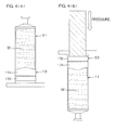
- FIGS. 4(A) and 4(B) Further, a gas tightness test was performed as shown in FIGS. 4(A) and 4(B) .
- the syringe barrel 11 was filled with pure water W, then capped with the gasket 13, and allowed to stand still.
- the pure water was used as a test liquid, and COP's 100-mL syringe barrel was used as the syringe barrel 11.
- the capped syringe barrel was allowed to stand still at a temperature of 40°C for 1 week.
- the gasket 13 was observed to check whether the test liquid intruded over the first projection 17A located on the distal side (upper side in FIG. 4(A) ) of the gasket 13 to reach the recess between the first projection 17A and the second projection 17B. Based on the observation results, where no liquid was present in the recess of the gasket, the gasket was rated as excellent ( ⁇ ). Where a small liquid droplet (having a size of not greater than 1mm) was present in the recess of the gasket, the gasket was rated as acceptable ( ⁇ ). Where a large liquid droplet (having a size of greater than 1 mm) was present in the recess of the gasket, the gasket was rated as unacceptable ( ⁇ ).
- the gasket was evaluated based on a press load required for sliding the gasket. A gasket requiring a maximum load of not greater than 40 N was rated as acceptable ( ⁇ ), and a gasket requiring a maximum load of greater than 40 N was rated as unacceptable ( ⁇ ).
- the gasket is excellent in gas tightness and slidability, if the product ⁇ of the contact pressure P1f and the width D1f of the first peak appearing on the distal side of the first projection 17A is 0.4 ⁇ ⁇ ⁇ 1.0.
- the gas tightness is poorer (see Comparative Example 1).
Landscapes
- Health & Medical Sciences (AREA)
- Engineering & Computer Science (AREA)
- Hematology (AREA)
- Anesthesiology (AREA)
- Biomedical Technology (AREA)
- Heart & Thoracic Surgery (AREA)
- Vascular Medicine (AREA)
- Life Sciences & Earth Sciences (AREA)
- Animal Behavior & Ethology (AREA)
- General Health & Medical Sciences (AREA)
- Public Health (AREA)
- Veterinary Medicine (AREA)
- General Engineering & Computer Science (AREA)
- Mechanical Engineering (AREA)
- Infusion, Injection, And Reservoir Apparatuses (AREA)
Abstract
Description
- This application corresponds to Japanese Patent Application No.
2014-125210 - The present invention relates to a gasket to be used for a medical syringe, and a medical syringe.
- Syringes for use in medical applications typically include a syringe barrel, a plunger reciprocally movable in the syringe barrel, and a gasket attached to a distal end of the plunger.
- The gasket to be used for the syringes is required to have gas tightness and low-friction slidability. The gas tightness means that liquid drug is prevented from leaking outside during use and foreign matter is prevented from intruding from the outside. The low-friction slidability means that, when the syringe is used, a user can properly move the gasket by manipulating the plunger by one hand.
- The prior-art syringes ensure the low-friction slidability and the gas tightness with a silicone oil applied in the syringe barrel, but some liquid drugs are adversely influenced by the silicone. Therefore, it is desirable not to apply the silicone to the syringe barrel.
- From this viewpoint, a product called laminated gasket is often used, which includes a rubber gasket body having a surface laminated with a film having excellent slidability (e.g., a gasket laminated with a fluororesin film).
- When the laminated gasket is inserted in the syringe barrel, a maximum diameter portion (peak portion) of the gasket receives a counter force from an inner surface of the syringe barrel to shrink and, therefore, a portion of the fluororesin film of the maximum diameter portion is liable to be wrinkled or slacked. At this time, a gap is formed between the wrinkled or slacked peak portion of the gasket and the inner surface of the syringe barrel. This may reduce the gas tightness of the gasket, thereby causing the liquid leakage and the intrusion of foreign matter.
- In
JP2892617B - If the distal portion of the gasket has an excessively small curvature radius R in peripheral section, however, the lamination film is more liable to be torn. Further, the gasket is more liable to be inclined in various steps of the gasket production process.
- In
WO2008/078467 , on the other hand, the distal portion of the gasket has a curvature radius of not less than 0.7 mm in peripheral section, so that the gas tightness can be ensured even if the gasket is inclined. If the distal portion has an increased curvature radius R in peripheral section, however, the slidability is improved but the gas tightness is disadvantageously reduced. - In view of the foregoing, it is a principal object of the present invention to provide a gasket having a novel structure ensuring both the gas tightness and the low-friction slidability required for the gasket.
- It is another object of the present invention to provide a medical syringe employing the gasket.
- According to an inventive aspect of claim 1, there is provided a gasket to be used for a medial syringe, the gasket including: a rubber body having a liquid contact portion and a sliding portion to be brought into contact with an inner surface of a syringe barrel; and a lamination film provided on a surface of the rubber body; wherein the sliding portion includes at least a first annular projection, an annular recess and a second annular projection arranged in this order in a direction rearward from a distal portion of the gasket serving as the liquid contact portion; wherein the first projection is designed so that a first peak appears adjacent the distal portion of the gasket when the gasket is fitted in the syringe barrel and a product α of a contact pressure P1f and a width D1f of the first peak is 0.4 ≤ α ≤ 1.0 as determined by an FEM analysis.
- According to an inventive aspect of claim 2, the lamination film is made of PTFE in the gasket of claim 1.
- According to an inventive aspect of claim 3, two peaks including a distal peak and a rear side peak appear on the first projection of the gasket of claim 1.
- According to an inventive aspect of claim 4, a product β of a contact pressure P2 and a width D2 for the second projection of the gasket of claim 1 is 0.2 ≤ β ≤ 0.6 as determined by the FEM analysis.
- According to an inventive aspect of claim 5, an edge portion of the first projection adjacent to the distal portion has a curvature radius of not greater than 1.2 mm in the gasket of claim 1.
- According to an inventive aspect of claim 6, there is provided a medical syringe, which includes a tubular syringe barrel, a plunger combined with the syringe barrel and movable in the syringe barrel, and a gasket of claim 1 attached to a distal end of the plunger.
- In the conception of the present invention, it was found that the gas tightness and the low-friction slidability required for the gasket are related with the contact pressure at which the gasket presses the syringe barrel. That is, when an FEM (finite element method) analysis was performed with the gasket inserted in the syringe barrel, it was found that the gas tightness and the low-friction slidability were influenced by the contact pressure at which the gasket presses the syringe barrel.
- Further, it was found that the gas tightness is significantly influenced by the contact pressure of the projection (first projection) adjacent to the distal portion of the gasket. Particularly, it was found that the product of the contact pressure (P1f) and the width (axial width D1f) of the peak appearing on the distal side of the first projection is a very important factor for the gas tightness.
- It was confirmed that the gas tightness is impaired if the product of the contact pressure and the width is excessively small, and the slidability is impaired if the product is excessively great.
- Further, it was confirmed that the sliding portion preferably includes the first projection as well as the annular second projection arranged in this order in the direction rearward from the distal portion for smooth sliding and capping.
- It was also confirmed that the slidability is impaired if the product of the contact pressure (P2) and the axial width (D2) for the second projection is excessively great, and the gasket is liable to suffer from inconveniences, e.g., the gasket is liable to be obliquely inclined or permit intrusion of outside air, if the product is excessively small.
- Further, it was found that the first projection is desirably configured so as to have a double-peak contact pressure profile as determined by the FEM analysis. Where the first projection has the double-peak contact pressure profile, the gasket has an improved gas tightness and, in addition, the gas tightness can be ensured even if the gasket is inclined during the handling.
- According to the present invention, the gasket has an improved gas tightness and, hence, improves the liquid drug storage stability when being used for a prefilled syringe.
- Since the gasket slidability is not reduced, a user can use the syringe with a reduced load.
- Further, the gas tightness and the slidability of the gasket can be estimated by the FEM analysis in the gasket production process, so that a safer gasket can be designed in a shorter period of time.
-
-
FIG. 1 is an exploded diagram illustrating a medical syringe according to an embodiment of the present invention. -
FIG. 2 is a diagram of a laminated gasket according to the embodiment of the present invention with a half of the gasket illustrated in section. -
FIG. 3 is a diagram showing positions subjected to the FEM analysis. -
FIG. 4 is a diagram for explaining a gas tightness test and a slidability test. - With reference to the attached drawings, one embodiment of the present invention will hereinafter be described specifically.
-
FIG. 1 is an exploded diagram illustrating a medical syringe, i.e., a so-called prefilled syringe, according to the embodiment of the present invention. InFIG. 1 , a half of asyringe barrel 11 and a half of agasket 13 are illustrated in section. - Referring to
FIG. 1 , the prefilledsyringe 10 includes a hollowcylindrical syringe barrel 11, aplunger 12 combined with thesyringe barrel 11 and reciprocally movable in thesyringe barrel 11, and agasket 13 attached to a distal end of theplunger 12. Thegasket 13 is a so-called laminated gasket, which includes amain body 14 made of an elastic material (a rubber or an elastomer) and alamination film 15 provided on a surface of themain body 14. Thegasket 13 includes two circumferential portions, i.e., afirst projection 17A and asecond projection 17B, serving as a sliding portion to be kept in gas-tight and liquid-tight contact with an innerperipheral surface 16 of thesyringe barrel 11. - The
plunger 12 includes a resin plate piece, for example, having a cross shape as seen in section, and ahead 18 provided at a distal end of the resin plate piece and fitted with thegasket 13. Thehead 18 is an integral part of theplunger 12 made of a resin and shaped in a male screw. - The
gasket 13 has a generally cylindrical shape having a short axis. Thegasket 13 has a distal end face, for example, having a conical center portion projecting at an obtuse angle, and a rear end face axially recessed into an engagement recess 21 shaped in a female screw. Thehead 18 of theplunger 12 is screwed into the engagement recess 21 of thegasket 13, whereby thegasket 13 is attached to the distal end of theplunger 12. -
FIG. 2 is a diagram showing only thegasket 13 ofFIG. 1 on an enlarged scale. InFIG. 2 , a half of thegasket 13 is illustrated in section. - Referring to
FIG. 2 , the structure of thegasket 13 according to this embodiment will be described in greater detail. - The
gasket 13 includes themain body 14, and thelamination film 15 provided on the surface of themain body 14. Themain body 14 is made of an elastomeric rubber (crosslinked rubber). - The type of the
lamination film 15 provided on the surface of themain body 14 is not particularly limited, as long as thelamination film 15 can prevent migration of components from the crosslinked rubber (main body 14) and is more excellent in slidability than the rubber, i.e., has a smaller friction coefficient than the rubber. - Exemplary materials for the
main body 14 and thelamination film 15 are shown below. - Examples of the rubber to be used as the material for the
main body 14 include butyl rubbers, isoprene rubbers, butadiene rubbers, styrene-butadiene rubbers, natural rubbers, chloroprene rubbers, nitrile rubbers such as acrylonitrile-butadiene rubbers, hydrogenated nitrile rubbers, norbornene rubbers, ethylene-propylene rubbers, ethylene-propylene-diene rubbers, acryl rubbers, ethylene-acrylate rubbers, fluororubbers, chlorosulfonated polyethylene rubbers, epichlorohydrin rubbers, silicone rubbers, urethane rubbers, polysulfide rubbers, phosphazene rubbers and 1,2-polybutadiene rubbers. - These rubbers may be used either alone or in combination.
- The rubber to be used for the
main body 14 is not limited to the aforementioned rubbers, but is preferably a butyl rubber and/or an ethylene-propylene-diene rubber (hereinafter referred to as EPDM rubber). - The butyl rubber is preferred because of its excellent gas permeation resistance and water vapor permeation resistance.
- A known butyl rubber compound may be used as the butyl rubber, but other examples of the butyl rubber include isobutylene-isoprene copolymer rubbers, halogenated isobutylene-isoprene copolymer rubbers (hereinafter referred to as halogenated butyl rubbers), and modification products of any of these rubbers. Examples of the modification products include bromination products of copolymers of isobutylene and p-methylstyrene. Particularly, the halogenated butyl rubbers are more preferred, and chlorinated butyl rubbers and brominated butyl rubbers are further more preferred for easy crosslinking.
- The EPDM rubber is preferred because of its excellent processability. The EPDM rubber includes a non-oil extension type EPDM rubber containing only a rubber component and an oil extension type EPDM rubber containing a rubber component and an extension oil. In the present invention, either type of the EPDM rubbers may be used. Examples of a diene monomer for the EPDM rubber include dicyclopentadiene, methylene norbornene, ethylidene norbornene, 1,4-hexadiene and cyclooctadiene.
- The halogenated butyl rubber and the EPDM rubber are advantageously used in combination because the resulting rubber is excellent in gas permeation resistance, water vapor permeation resistance and processability.
- In this embodiment, the
main body 14 is of the syringe gasket as a medical rubber product and, therefore, a butyl rubber having a lower gas permeability is preferably used as a principal rubber component. A triazine derivative crosslinking agent is preferably used as a crosslinking agent for cleanliness. - The
lamination film 15 is not particularly limited, but may be an inert film. At least one fluororesin selected from the group consisting of a polytetrafluoroethylene (PTFE), a modified polytetrafluoroethylene (modified PTFE, which is a copolymer of a 4F-monomer and a very small amount of a perfluoroalkoxide), a tetrafluoroethylene ethylene copolymer (ETFE), a tetrafluoroethylene perfluoroalkyl vinyl ether copolymer (PFA) and a polychlorotetrafluoroethylene (PCTFE), and/or an olefin resin are preferred for thelamination film 15 to provide excellent chemical resistance. - The
laminated gasket 13 according to this embodiment is produced by kneading ingredients blended in a predetermined blend radio by means of a sealed kneader, an open roll kneader or the like, forming the resulting kneaded product into an unvulcanized rubber sheet by means of a calender or a sheet forming machine, placing the unvulcanized rubber sheet and the inert film each having a predetermined weight and size in superposition in a die, and press-forming the unvulcanized rubber sheet and the inert film into a laminated gasket sheet by means of a vacuum press. - Conditions for the forming are not particularly limited, but may be properly determined. The forming temperature is preferably 155°C to 200°C, more preferably 165°C to 180°C. The forming period is preferably 1 to 20 minutes, more preferably 3 to 15 minutes, further more preferably 5 to 10 minutes. The die to be used for the forming preferably has a sliding surface forming portion having a smooth die surface mirror-finished so as to have an arithmetic average roughness Ra of not greater than 0.03 µm as measured with a cutoff value of 0.08 mm. With the use of this die, the laminated rubber member thus formed can have a surface roughness smaller than the original surface roughness of the inert film. The arithmetic average roughness Ra is preferably not greater than 0.02 µm, more preferably not greater than 0.015 µm.
- Thereafter, an unnecessary portion is cut away and removed from the formed gasket sheet. Then, the resulting product is cleaned, sterilized and dried, and then visually inspected. Thus, a primary gasket product is produced.
- A feature of the
gasket 13 according to this embodiment is that thegasket 13 includes thefirst projection 17A and thesecond projection 17B serving as the sliding portion to be kept in gas-tight and liquid-tight contact with the innerperipheral surface 16 of thesyringe barrel 11, and that thefirst projection 17A is designed so that a product of a contact pressure P1f and a width D1f is 0.4 ≤ α ≤ 1.0 as determined by an FEM analysis. - More specifically, the
first projection 17A is designed so that two peaks including a distal peak and a rear side peak appear and a product of a contact pressure P1f and a width D1f of the distal peak is 0.4 ≤ α ≤ 1.0. - Further, the
first projection 17A has a distal edge portion having a curvature radius R of not greater than 1.2 mm. - With this design, the
gasket 13 of this embodiment ensures the gas tightness and the low-friction slidability. - An FEM (Finite Element Method) analysis was performed on gaskets each having a shape as shown in
FIG. 2 , i.e., gaskets each having a sliding portion including afirst projection 17A and asecond projection 17B to be brought into contact with an innerperipheral surface 16 of asyringe barrel 11. A static implicit method was used for the analysis, and marc & mentat was used as an analysis software. - For production of the gaskets to be subjected to the analysis,
main bodies 14 were each made of a rubber having a hardness of 60, andlamination films 15 were each made of a PTFE (having a tensile elasticity of 485 MPa and a Poisson's ratio of 0.46). - For the
first projection 17A of thegasket 13 fitted in thesyringe barrel 11, a product α of a contact pressure P1f and a width D1f of a distal peak appearing at an analysis position in a contact pressure profile as shown inFIG. 3 was calculated. - Further, a product β of a contact pressure P2 and a width D2 of a peak observed at the
second projection 17B by the FEM analysis was also calculated. - Further, a gas tightness test was performed as shown in
FIGS. 4(A) and 4(B) . - As shown in
FIG. 4(A) , thesyringe barrel 11 was filled with pure water W, then capped with thegasket 13, and allowed to stand still. - As described above, the pure water was used as a test liquid, and COP's 100-mL syringe barrel was used as the
syringe barrel 11. The capped syringe barrel was allowed to stand still at a temperature of 40°C for 1 week. - The
gasket 13 was observed to check whether the test liquid intruded over thefirst projection 17A located on the distal side (upper side inFIG. 4(A) ) of thegasket 13 to reach the recess between thefirst projection 17A and thesecond projection 17B. Based on the observation results, where no liquid was present in the recess of the gasket, the gasket was rated as excellent (○). Where a small liquid droplet (having a size of not greater than 1mm) was present in the recess of the gasket, the gasket was rated as acceptable (Δ). Where a large liquid droplet (having a size of greater than 1 mm) was present in the recess of the gasket, the gasket was rated as unacceptable (×). - Further, a slidability test was performed at a room temperature by sliding the gasket at a test speed of 5 mm/s by means of an autograph (available from Shimadzu Corporation) as shown in
FIG. 4(B) . - The gasket was evaluated based on a press load required for sliding the gasket. A gasket requiring a maximum load of not greater than 40 N was rated as acceptable (○), and a gasket requiring a maximum load of greater than 40 N was rated as unacceptable (×).
- The results are collectively shown below in Table 1.
Table 1 Comparative Example 1 Comparative Example 2 Example 1 Example 2 Example 3 Example 4 Example 5 Curvature radius R of distal edge portion of first projection 1.5 0.7 1 0.85 1.2 0.75 0.75 First projection Diameter 33.2 33.3 33.3 33.3 33.2 33.3 33.2 Width 3.2 3.6 3.9 3.6 3.2 3.9 3.6 Second projection Diameter 33.4 33.6 33.6 33.5 33.6 33.6 33.6 Width 1.2 1.7 1.7 1.7 1.7 1.7 1.7 P1f·D1f (α) 0.22 1.1 0.52 0.75 0.41 0.98 0.99 P2·D2 (β) 0.36 0.54 0.57 0.54 0.52 0.51 0.52 Gas tightness × ○ ○ ○ Δ ○ ○ Slidability ○ × ○ ○ ○ ○ ○ ×: Unacceptable Δ, ○: Acceptable - As can be understood from Table 1, the gasket is excellent in gas tightness and slidability, if the product α of the contact pressure P1f and the width D1f of the first peak appearing on the distal side of the
first projection 17A is 0.4 ≤ α ≤ 1.0. - The results for Comparative Example 2 indicate that, if the product α of the contact pressure P1f and the width D1f of the first peak of the
first projection 17A falls outside the aforementioned range, i.e., the product α is greater than 1.0, the slidability is impaired. - If the distal edge portion of the
first projection 17A has a curvature radius R of not greater than 1.2 mm, i.e., the distal edge portion of thefirst projection 17A has a greater curvature radius R (e.g., has a chamfered surface), the gas tightness is poorer (see Comparative Example 1). - The present invention is not limited to the embodiment and the inventive examples described above, but various modifications may be made within the scope of the present invention.
Claims (6)
- A gasket to be used for a medial syringe, the gasket comprising:a rubber body having a liquid contact portion and a sliding portion to be brought into contact with an inner surface of a syringe barrel; anda lamination film provided on a surface of the rubber body;wherein the sliding portion includes at least a first annular projection, an annular recess and a second annular projection arranged in this order in a direction rearward from a distal portion of the gasket serving as the liquid contact portion;wherein the first projection is designed so that a first peak appears adjacent the distal portion of the gasket when the gasket is fitted in the syringe barrel and a product α of a contact pressure P1f and a width D1f of the first peak is 0.4 ≤ α ≤ 1.0 as determined by an FEM analysis.
- The gasket according to claim 1, wherein the lamination film is made of PTFE.
- The gasket according to claim 1 or 2, wherein two peaks including a distal peak and a rear side peak appear on the first projection.
- The gasket according to any of claims 1 to 3, wherein a product β of a contact pressure P2 and a width D2 for the second projection is 0.2 ≤ β ≤ 0.6 as determined by the FEM analysis.
- The gasket according to any of claims 1 to 4, wherein an edge portion of the first projection adjacent to the distal portion has a curvature radius of not greater than 1.2 mm.
- A medical syringe, comprising:a tubular syringe barrel;a plunger combined with the syringe barrel and movable in the syringe barrel; anda gasket of any of claims 1 to 5 attached to a distal end of the plunger.
Applications Claiming Priority (1)
| Application Number | Priority Date | Filing Date | Title |
|---|---|---|---|
| JP2014125210A JP6270275B2 (en) | 2014-06-18 | 2014-06-18 | Gaskets and medical syringes applied to medical syringes |
Publications (2)
| Publication Number | Publication Date |
|---|---|
| EP2957310A1 true EP2957310A1 (en) | 2015-12-23 |
| EP2957310B1 EP2957310B1 (en) | 2019-06-12 |
Family
ID=53016523
Family Applications (1)
| Application Number | Title | Priority Date | Filing Date |
|---|---|---|---|
| EP15165532.1A Active EP2957310B1 (en) | 2014-06-18 | 2015-04-28 | Gasket to be used for medical syringe, and medical syringe |
Country Status (5)
| Country | Link |
|---|---|
| US (1) | US9623186B2 (en) |
| EP (1) | EP2957310B1 (en) |
| JP (1) | JP6270275B2 (en) |
| KR (1) | KR20150145171A (en) |
| CN (1) | CN105288796B (en) |
Cited By (8)
| Publication number | Priority date | Publication date | Assignee | Title |
|---|---|---|---|---|
| EP3342439A1 (en) * | 2016-12-28 | 2018-07-04 | Sumitomo Rubber Industries, Ltd. | Medical syringe |
| EP3376076A1 (en) * | 2017-03-14 | 2018-09-19 | Sumitomo Rubber Industries, Ltd. | Gasket |
| USD870278S1 (en) | 2017-01-13 | 2019-12-17 | Sio2 Medical Products, Inc. | Syringe plunger assembly |
| US10561795B2 (en) | 2013-10-07 | 2020-02-18 | Sio2 Medical Products, Inc. | Convertible plungers, film coated plungers and related syringe assemblies |
| US10765812B2 (en) | 2015-07-14 | 2020-09-08 | Sio2 Medical Products, Inc. | Convertible plungers and methods for assembling the same in a medical barrel |
| EP3659648A4 (en) * | 2017-07-24 | 2020-10-28 | Mitsubishi Gas Chemical Company, Inc. | Syringe barrel and syringe |
| US10850042B2 (en) | 2014-09-10 | 2020-12-01 | Sio2 Medical Products, Inc. | Three-position plungers, film coated plungers and related syringe assemblies |
| US10918800B2 (en) | 2016-05-31 | 2021-02-16 | Sio2 Medical Products, Inc. | Convertible plungers and methods for assembling the same in a medical barrel |
Families Citing this family (8)
| Publication number | Priority date | Publication date | Assignee | Title |
|---|---|---|---|---|
| US10182969B2 (en) | 2015-03-10 | 2019-01-22 | Regeneron Pharmaceuticals, Inc. | Aseptic piercing system and method |
| USD788296S1 (en) * | 2015-10-14 | 2017-05-30 | Sumitomo Rubber Industries, Ltd. | Gasket for syringe |
| USD787668S1 (en) * | 2015-10-14 | 2017-05-23 | Sumitomo Rubber Industries, Ltd. | Gasket for syringe |
| USD788912S1 (en) * | 2015-10-14 | 2017-06-06 | Sumitomo Rubber Industries, Ltd. | Gasket for syringe |
| USD788297S1 (en) * | 2015-10-14 | 2017-05-30 | Sumitomo Rubber Industries, Ltd. | Gasket for syringe |
| JP6883253B2 (en) * | 2016-03-30 | 2021-06-09 | 住友ゴム工業株式会社 | Gasket manufacturing method |
| ES2919934T3 (en) | 2017-05-05 | 2022-07-29 | Regeneron Pharma | Autoinjector and related procedures for use |
| USD1007676S1 (en) | 2021-11-16 | 2023-12-12 | Regeneron Pharmaceuticals, Inc. | Wearable autoinjector |
Citations (7)
| Publication number | Priority date | Publication date | Assignee | Title |
|---|---|---|---|---|
| EP0026940A1 (en) * | 1979-10-09 | 1981-04-15 | Terumo Corporation | Syringe and gasket therefor |
| US5314416A (en) * | 1992-06-22 | 1994-05-24 | Sherwood Medical Company | Low friction syring assembly |
| JP2892617B2 (en) | 1996-06-18 | 1999-05-17 | 株式会社大協精工 | Syringe stopper |
| WO2008078467A1 (en) | 2006-12-27 | 2008-07-03 | Daikyo Seiko, Ltd. | Piston for syringe |
| WO2009128265A1 (en) * | 2008-04-16 | 2009-10-22 | 味の素株式会社 | Syringe |
| JP2013138697A (en) * | 2011-12-28 | 2013-07-18 | Sumitomo Rubber Ind Ltd | Laminated gasket |
| EP2703025A1 (en) * | 2012-08-30 | 2014-03-05 | Sumitomo Rubber Industries, Ltd. | Laminated gasket |
Family Cites Families (4)
| Publication number | Priority date | Publication date | Assignee | Title |
|---|---|---|---|---|
| JP3387775B2 (en) * | 1997-05-22 | 2003-03-17 | 株式会社大協精工 | Sealing stopper for syringe and prefilled syringe |
| US6511459B1 (en) * | 2000-09-29 | 2003-01-28 | Mallinckrodt Inc. | Syringe plunger having an improved sealing ability |
| JP4847632B1 (en) * | 2011-05-20 | 2011-12-28 | 有限会社コーキ・エンジニアリング | Medical stopper surface-coated skived film, medical stopper using the film, prefilled syringe using the stopper, and method for producing the film |
| JP5717593B2 (en) * | 2011-08-31 | 2015-05-13 | 住友ゴム工業株式会社 | Mold for molding gasket for prefilled syringe |
-
2014
- 2014-06-18 JP JP2014125210A patent/JP6270275B2/en not_active Expired - Fee Related
-
2015
- 2015-03-11 KR KR1020150033765A patent/KR20150145171A/en unknown
- 2015-04-16 CN CN201510181546.6A patent/CN105288796B/en not_active Expired - Fee Related
- 2015-04-28 EP EP15165532.1A patent/EP2957310B1/en active Active
- 2015-06-03 US US14/729,921 patent/US9623186B2/en not_active Expired - Fee Related
Patent Citations (8)
| Publication number | Priority date | Publication date | Assignee | Title |
|---|---|---|---|---|
| EP0026940A1 (en) * | 1979-10-09 | 1981-04-15 | Terumo Corporation | Syringe and gasket therefor |
| US5314416A (en) * | 1992-06-22 | 1994-05-24 | Sherwood Medical Company | Low friction syring assembly |
| JP2892617B2 (en) | 1996-06-18 | 1999-05-17 | 株式会社大協精工 | Syringe stopper |
| WO2008078467A1 (en) | 2006-12-27 | 2008-07-03 | Daikyo Seiko, Ltd. | Piston for syringe |
| EP2103320A1 (en) * | 2006-12-27 | 2009-09-23 | Daikyo Seiko, LTD. | Piston for syringe |
| WO2009128265A1 (en) * | 2008-04-16 | 2009-10-22 | 味の素株式会社 | Syringe |
| JP2013138697A (en) * | 2011-12-28 | 2013-07-18 | Sumitomo Rubber Ind Ltd | Laminated gasket |
| EP2703025A1 (en) * | 2012-08-30 | 2014-03-05 | Sumitomo Rubber Industries, Ltd. | Laminated gasket |
Cited By (10)
| Publication number | Priority date | Publication date | Assignee | Title |
|---|---|---|---|---|
| US10561795B2 (en) | 2013-10-07 | 2020-02-18 | Sio2 Medical Products, Inc. | Convertible plungers, film coated plungers and related syringe assemblies |
| US10850042B2 (en) | 2014-09-10 | 2020-12-01 | Sio2 Medical Products, Inc. | Three-position plungers, film coated plungers and related syringe assemblies |
| US10765812B2 (en) | 2015-07-14 | 2020-09-08 | Sio2 Medical Products, Inc. | Convertible plungers and methods for assembling the same in a medical barrel |
| US10918800B2 (en) | 2016-05-31 | 2021-02-16 | Sio2 Medical Products, Inc. | Convertible plungers and methods for assembling the same in a medical barrel |
| US11896807B2 (en) | 2016-05-31 | 2024-02-13 | Sio2 Material Products, Inc | Convertible plungers and methods for assembling the same in a medical barrel |
| EP3342439A1 (en) * | 2016-12-28 | 2018-07-04 | Sumitomo Rubber Industries, Ltd. | Medical syringe |
| USD870278S1 (en) | 2017-01-13 | 2019-12-17 | Sio2 Medical Products, Inc. | Syringe plunger assembly |
| EP3376076A1 (en) * | 2017-03-14 | 2018-09-19 | Sumitomo Rubber Industries, Ltd. | Gasket |
| CN108570162A (en) * | 2017-03-14 | 2018-09-25 | 住友橡胶工业株式会社 | Gasket |
| EP3659648A4 (en) * | 2017-07-24 | 2020-10-28 | Mitsubishi Gas Chemical Company, Inc. | Syringe barrel and syringe |
Also Published As
| Publication number | Publication date |
|---|---|
| US20150367076A1 (en) | 2015-12-24 |
| JP2016002355A (en) | 2016-01-12 |
| US9623186B2 (en) | 2017-04-18 |
| EP2957310B1 (en) | 2019-06-12 |
| CN105288796B (en) | 2020-02-14 |
| CN105288796A (en) | 2016-02-03 |
| KR20150145171A (en) | 2015-12-29 |
| JP6270275B2 (en) | 2018-01-31 |
Similar Documents
| Publication | Publication Date | Title |
|---|---|---|
| EP2957310B1 (en) | Gasket to be used for medical syringe, and medical syringe | |
| EP2926851B1 (en) | Gasket for prefilled syringe, and production method therefor | |
| EP3045192B1 (en) | Gasket for pre-filled syringe | |
| EP2703025B1 (en) | Laminated gasket | |
| EP3231468B1 (en) | Gasket, and medical syringe | |
| US9717858B2 (en) | Gasket for prefilled syringe and prefilled syringe | |
| JP5855598B2 (en) | Prefilled syringe gasket | |
| JP6215546B2 (en) | Gasket for prefilled syringe | |
| EP2803377B1 (en) | A combination of a medical gasket and a plunger for a prefilled syringe | |
| EP2803378A1 (en) | Gasket for syringe | |
| EP3342439B1 (en) | Medical syringe | |
| EP2902060B1 (en) | Medical gasket manufacturing method | |
| EP3058975B1 (en) | Prefilled syringe, gasket for use in prefilled syringe, and gasket production method | |
| JP5922404B2 (en) | Laminated gasket | |
| EP3278829A1 (en) | Medical syringe, gasket to be used for syringe, and gasket production method | |
| EP3219347B1 (en) | Gasket for use in a syringe | |
| JP7209175B2 (en) | METHOD FOR MANUFACTURING MEDICAL RUBBER PRODUCTS | |
| JP2015167677A (en) | Glass syringe and prefilled syringe | |
| JP2016077355A (en) | Prefilled syringe gasket and prefilled syringe |
Legal Events
| Date | Code | Title | Description |
|---|---|---|---|
| PUAI | Public reference made under article 153(3) epc to a published international application that has entered the european phase |
Free format text: ORIGINAL CODE: 0009012 |
|
| AK | Designated contracting states |
Kind code of ref document: A1 Designated state(s): AL AT BE BG CH CY CZ DE DK EE ES FI FR GB GR HR HU IE IS IT LI LT LU LV MC MK MT NL NO PL PT RO RS SE SI SK SM TR |
|
| AX | Request for extension of the european patent |
Extension state: BA ME |
|
| 17P | Request for examination filed |
Effective date: 20160331 |
|
| RBV | Designated contracting states (corrected) |
Designated state(s): AL AT BE BG CH CY CZ DE DK EE ES FI FR GB GR HR HU IE IS IT LI LT LU LV MC MK MT NL NO PL PT RO RS SE SI SK SM TR |
|
| GRAP | Despatch of communication of intention to grant a patent |
Free format text: ORIGINAL CODE: EPIDOSNIGR1 |
|
| STAA | Information on the status of an ep patent application or granted ep patent |
Free format text: STATUS: GRANT OF PATENT IS INTENDED |
|
| RAP1 | Party data changed (applicant data changed or rights of an application transferred) |
Owner name: SUMITOMO RUBBER INDUSTRIES, LTD. |
|
| INTG | Intention to grant announced |
Effective date: 20181204 |
|
| GRAS | Grant fee paid |
Free format text: ORIGINAL CODE: EPIDOSNIGR3 |
|
| GRAA | (expected) grant |
Free format text: ORIGINAL CODE: 0009210 |
|
| STAA | Information on the status of an ep patent application or granted ep patent |
Free format text: STATUS: THE PATENT HAS BEEN GRANTED |
|
| AK | Designated contracting states |
Kind code of ref document: B1 Designated state(s): AL AT BE BG CH CY CZ DE DK EE ES FI FR GB GR HR HU IE IS IT LI LT LU LV MC MK MT NL NO PL PT RO RS SE SI SK SM TR |
|
| REG | Reference to a national code |
Ref country code: GB Ref legal event code: FG4D |
|
| REG | Reference to a national code |
Ref country code: CH Ref legal event code: EP |
|
| REG | Reference to a national code |
Ref country code: AT Ref legal event code: REF Ref document number: 1141772 Country of ref document: AT Kind code of ref document: T Effective date: 20190615 |
|
| REG | Reference to a national code |
Ref country code: DE Ref legal event code: R096 Ref document number: 602015031657 Country of ref document: DE |
|
| REG | Reference to a national code |
Ref country code: IE Ref legal event code: FG4D |
|
| REG | Reference to a national code |
Ref country code: NL Ref legal event code: MP Effective date: 20190612 |
|
| REG | Reference to a national code |
Ref country code: LT Ref legal event code: MG4D |
|
| PG25 | Lapsed in a contracting state [announced via postgrant information from national office to epo] |
Ref country code: SE Free format text: LAPSE BECAUSE OF FAILURE TO SUBMIT A TRANSLATION OF THE DESCRIPTION OR TO PAY THE FEE WITHIN THE PRESCRIBED TIME-LIMIT Effective date: 20190612 Ref country code: HR Free format text: LAPSE BECAUSE OF FAILURE TO SUBMIT A TRANSLATION OF THE DESCRIPTION OR TO PAY THE FEE WITHIN THE PRESCRIBED TIME-LIMIT Effective date: 20190612 Ref country code: FI Free format text: LAPSE BECAUSE OF FAILURE TO SUBMIT A TRANSLATION OF THE DESCRIPTION OR TO PAY THE FEE WITHIN THE PRESCRIBED TIME-LIMIT Effective date: 20190612 Ref country code: NO Free format text: LAPSE BECAUSE OF FAILURE TO SUBMIT A TRANSLATION OF THE DESCRIPTION OR TO PAY THE FEE WITHIN THE PRESCRIBED TIME-LIMIT Effective date: 20190912 Ref country code: AL Free format text: LAPSE BECAUSE OF FAILURE TO SUBMIT A TRANSLATION OF THE DESCRIPTION OR TO PAY THE FEE WITHIN THE PRESCRIBED TIME-LIMIT Effective date: 20190612 Ref country code: LT Free format text: LAPSE BECAUSE OF FAILURE TO SUBMIT A TRANSLATION OF THE DESCRIPTION OR TO PAY THE FEE WITHIN THE PRESCRIBED TIME-LIMIT Effective date: 20190612 |
|
| PG25 | Lapsed in a contracting state [announced via postgrant information from national office to epo] |
Ref country code: GR Free format text: LAPSE BECAUSE OF FAILURE TO SUBMIT A TRANSLATION OF THE DESCRIPTION OR TO PAY THE FEE WITHIN THE PRESCRIBED TIME-LIMIT Effective date: 20190913 Ref country code: RS Free format text: LAPSE BECAUSE OF FAILURE TO SUBMIT A TRANSLATION OF THE DESCRIPTION OR TO PAY THE FEE WITHIN THE PRESCRIBED TIME-LIMIT Effective date: 20190612 Ref country code: BG Free format text: LAPSE BECAUSE OF FAILURE TO SUBMIT A TRANSLATION OF THE DESCRIPTION OR TO PAY THE FEE WITHIN THE PRESCRIBED TIME-LIMIT Effective date: 20190912 Ref country code: LV Free format text: LAPSE BECAUSE OF FAILURE TO SUBMIT A TRANSLATION OF THE DESCRIPTION OR TO PAY THE FEE WITHIN THE PRESCRIBED TIME-LIMIT Effective date: 20190612 |
|
| REG | Reference to a national code |
Ref country code: AT Ref legal event code: MK05 Ref document number: 1141772 Country of ref document: AT Kind code of ref document: T Effective date: 20190612 |
|
| PG25 | Lapsed in a contracting state [announced via postgrant information from national office to epo] |
Ref country code: NL Free format text: LAPSE BECAUSE OF FAILURE TO SUBMIT A TRANSLATION OF THE DESCRIPTION OR TO PAY THE FEE WITHIN THE PRESCRIBED TIME-LIMIT Effective date: 20190612 Ref country code: AT Free format text: LAPSE BECAUSE OF FAILURE TO SUBMIT A TRANSLATION OF THE DESCRIPTION OR TO PAY THE FEE WITHIN THE PRESCRIBED TIME-LIMIT Effective date: 20190612 Ref country code: EE Free format text: LAPSE BECAUSE OF FAILURE TO SUBMIT A TRANSLATION OF THE DESCRIPTION OR TO PAY THE FEE WITHIN THE PRESCRIBED TIME-LIMIT Effective date: 20190612 Ref country code: CZ Free format text: LAPSE BECAUSE OF FAILURE TO SUBMIT A TRANSLATION OF THE DESCRIPTION OR TO PAY THE FEE WITHIN THE PRESCRIBED TIME-LIMIT Effective date: 20190612 Ref country code: SK Free format text: LAPSE BECAUSE OF FAILURE TO SUBMIT A TRANSLATION OF THE DESCRIPTION OR TO PAY THE FEE WITHIN THE PRESCRIBED TIME-LIMIT Effective date: 20190612 Ref country code: RO Free format text: LAPSE BECAUSE OF FAILURE TO SUBMIT A TRANSLATION OF THE DESCRIPTION OR TO PAY THE FEE WITHIN THE PRESCRIBED TIME-LIMIT Effective date: 20190612 Ref country code: PT Free format text: LAPSE BECAUSE OF FAILURE TO SUBMIT A TRANSLATION OF THE DESCRIPTION OR TO PAY THE FEE WITHIN THE PRESCRIBED TIME-LIMIT Effective date: 20191014 |
|
| PG25 | Lapsed in a contracting state [announced via postgrant information from national office to epo] |
Ref country code: SM Free format text: LAPSE BECAUSE OF FAILURE TO SUBMIT A TRANSLATION OF THE DESCRIPTION OR TO PAY THE FEE WITHIN THE PRESCRIBED TIME-LIMIT Effective date: 20190612 Ref country code: IS Free format text: LAPSE BECAUSE OF FAILURE TO SUBMIT A TRANSLATION OF THE DESCRIPTION OR TO PAY THE FEE WITHIN THE PRESCRIBED TIME-LIMIT Effective date: 20191012 Ref country code: IT Free format text: LAPSE BECAUSE OF FAILURE TO SUBMIT A TRANSLATION OF THE DESCRIPTION OR TO PAY THE FEE WITHIN THE PRESCRIBED TIME-LIMIT Effective date: 20190612 Ref country code: ES Free format text: LAPSE BECAUSE OF FAILURE TO SUBMIT A TRANSLATION OF THE DESCRIPTION OR TO PAY THE FEE WITHIN THE PRESCRIBED TIME-LIMIT Effective date: 20190612 |
|
| REG | Reference to a national code |
Ref country code: DE Ref legal event code: R097 Ref document number: 602015031657 Country of ref document: DE |
|
| PG25 | Lapsed in a contracting state [announced via postgrant information from national office to epo] |
Ref country code: TR Free format text: LAPSE BECAUSE OF FAILURE TO SUBMIT A TRANSLATION OF THE DESCRIPTION OR TO PAY THE FEE WITHIN THE PRESCRIBED TIME-LIMIT Effective date: 20190612 |
|
| PLBE | No opposition filed within time limit |
Free format text: ORIGINAL CODE: 0009261 |
|
| STAA | Information on the status of an ep patent application or granted ep patent |
Free format text: STATUS: NO OPPOSITION FILED WITHIN TIME LIMIT |
|
| PG25 | Lapsed in a contracting state [announced via postgrant information from national office to epo] |
Ref country code: DK Free format text: LAPSE BECAUSE OF FAILURE TO SUBMIT A TRANSLATION OF THE DESCRIPTION OR TO PAY THE FEE WITHIN THE PRESCRIBED TIME-LIMIT Effective date: 20190612 Ref country code: PL Free format text: LAPSE BECAUSE OF FAILURE TO SUBMIT A TRANSLATION OF THE DESCRIPTION OR TO PAY THE FEE WITHIN THE PRESCRIBED TIME-LIMIT Effective date: 20190612 |
|
| 26N | No opposition filed |
Effective date: 20200313 |
|
| PG25 | Lapsed in a contracting state [announced via postgrant information from national office to epo] |
Ref country code: IS Free format text: LAPSE BECAUSE OF FAILURE TO SUBMIT A TRANSLATION OF THE DESCRIPTION OR TO PAY THE FEE WITHIN THE PRESCRIBED TIME-LIMIT Effective date: 20200224 Ref country code: SI Free format text: LAPSE BECAUSE OF FAILURE TO SUBMIT A TRANSLATION OF THE DESCRIPTION OR TO PAY THE FEE WITHIN THE PRESCRIBED TIME-LIMIT Effective date: 20190612 |
|
| PG2D | Information on lapse in contracting state deleted |
Ref country code: IS |
|
| REG | Reference to a national code |
Ref country code: DE Ref legal event code: R119 Ref document number: 602015031657 Country of ref document: DE |
|
| PG25 | Lapsed in a contracting state [announced via postgrant information from national office to epo] |
Ref country code: MC Free format text: LAPSE BECAUSE OF FAILURE TO SUBMIT A TRANSLATION OF THE DESCRIPTION OR TO PAY THE FEE WITHIN THE PRESCRIBED TIME-LIMIT Effective date: 20190612 |
|
| REG | Reference to a national code |
Ref country code: CH Ref legal event code: PL |
|
| PG25 | Lapsed in a contracting state [announced via postgrant information from national office to epo] |
Ref country code: FR Free format text: LAPSE BECAUSE OF NON-PAYMENT OF DUE FEES Effective date: 20200430 Ref country code: LU Free format text: LAPSE BECAUSE OF NON-PAYMENT OF DUE FEES Effective date: 20200428 Ref country code: LI Free format text: LAPSE BECAUSE OF NON-PAYMENT OF DUE FEES Effective date: 20200430 Ref country code: CH Free format text: LAPSE BECAUSE OF NON-PAYMENT OF DUE FEES Effective date: 20200430 Ref country code: DE Free format text: LAPSE BECAUSE OF NON-PAYMENT OF DUE FEES Effective date: 20201103 |
|
| REG | Reference to a national code |
Ref country code: BE Ref legal event code: MM Effective date: 20200430 |
|
| PG25 | Lapsed in a contracting state [announced via postgrant information from national office to epo] |
Ref country code: BE Free format text: LAPSE BECAUSE OF NON-PAYMENT OF DUE FEES Effective date: 20200430 |
|
| GBPC | Gb: european patent ceased through non-payment of renewal fee |
Effective date: 20200428 |
|
| PG25 | Lapsed in a contracting state [announced via postgrant information from national office to epo] |
Ref country code: GB Free format text: LAPSE BECAUSE OF NON-PAYMENT OF DUE FEES Effective date: 20200428 Ref country code: IE Free format text: LAPSE BECAUSE OF NON-PAYMENT OF DUE FEES Effective date: 20200428 |
|
| PG25 | Lapsed in a contracting state [announced via postgrant information from national office to epo] |
Ref country code: MT Free format text: LAPSE BECAUSE OF FAILURE TO SUBMIT A TRANSLATION OF THE DESCRIPTION OR TO PAY THE FEE WITHIN THE PRESCRIBED TIME-LIMIT Effective date: 20190612 Ref country code: CY Free format text: LAPSE BECAUSE OF FAILURE TO SUBMIT A TRANSLATION OF THE DESCRIPTION OR TO PAY THE FEE WITHIN THE PRESCRIBED TIME-LIMIT Effective date: 20190612 |
|
| PG25 | Lapsed in a contracting state [announced via postgrant information from national office to epo] |
Ref country code: MK Free format text: LAPSE BECAUSE OF FAILURE TO SUBMIT A TRANSLATION OF THE DESCRIPTION OR TO PAY THE FEE WITHIN THE PRESCRIBED TIME-LIMIT Effective date: 20190612 |