EP2957204A1 - Facial cleansing apparatus using electric motor and spring, control method therefor, and recording medium recording program for performing control method - Google Patents
Facial cleansing apparatus using electric motor and spring, control method therefor, and recording medium recording program for performing control method Download PDFInfo
- Publication number
- EP2957204A1 EP2957204A1 EP13879154.6A EP13879154A EP2957204A1 EP 2957204 A1 EP2957204 A1 EP 2957204A1 EP 13879154 A EP13879154 A EP 13879154A EP 2957204 A1 EP2957204 A1 EP 2957204A1
- Authority
- EP
- European Patent Office
- Prior art keywords
- electric motor
- brushless electric
- rotor
- spring
- holder
- Prior art date
- Legal status (The legal status is an assumption and is not a legal conclusion. Google has not performed a legal analysis and makes no representation as to the accuracy of the status listed.)
- Granted
Links
Images






Classifications
-
- A—HUMAN NECESSITIES
- A47—FURNITURE; DOMESTIC ARTICLES OR APPLIANCES; COFFEE MILLS; SPICE MILLS; SUCTION CLEANERS IN GENERAL
- A47K—SANITARY EQUIPMENT; ACCESSORIES THEREFOR, e.g. TOILET ACCESSORIES
- A47K7/00—Body washing or cleaning implements
- A47K7/04—Mechanical washing or cleaning devices, hand or mechanically, i.e. power operated
- A47K7/043—Mechanical washing or cleaning devices, hand or mechanically, i.e. power operated hand operated
-
- A—HUMAN NECESSITIES
- A47—FURNITURE; DOMESTIC ARTICLES OR APPLIANCES; COFFEE MILLS; SPICE MILLS; SUCTION CLEANERS IN GENERAL
- A47K—SANITARY EQUIPMENT; ACCESSORIES THEREFOR, e.g. TOILET ACCESSORIES
- A47K7/00—Body washing or cleaning implements
- A47K7/04—Mechanical washing or cleaning devices, hand or mechanically, i.e. power operated
-
- A—HUMAN NECESSITIES
- A45—HAND OR TRAVELLING ARTICLES
- A45D—HAIRDRESSING OR SHAVING EQUIPMENT; EQUIPMENT FOR COSMETICS OR COSMETIC TREATMENTS, e.g. FOR MANICURING OR PEDICURING
- A45D44/00—Other cosmetic or toiletry articles, e.g. for hairdressers' rooms
-
- A—HUMAN NECESSITIES
- A46—BRUSHWARE
- A46B—BRUSHES
- A46B13/00—Brushes with driven brush bodies or carriers
- A46B13/008—Disc-shaped brush bodies
-
- A—HUMAN NECESSITIES
- A46—BRUSHWARE
- A46B—BRUSHES
- A46B13/00—Brushes with driven brush bodies or carriers
- A46B13/02—Brushes with driven brush bodies or carriers power-driven carriers
- A46B13/026—Brushes which automatically reverse direction of rotation, e.g. using gravity switches
-
- A—HUMAN NECESSITIES
- A61—MEDICAL OR VETERINARY SCIENCE; HYGIENE
- A61H—PHYSICAL THERAPY APPARATUS, e.g. DEVICES FOR LOCATING OR STIMULATING REFLEX POINTS IN THE BODY; ARTIFICIAL RESPIRATION; MASSAGE; BATHING DEVICES FOR SPECIAL THERAPEUTIC OR HYGIENIC PURPOSES OR SPECIFIC PARTS OF THE BODY
- A61H23/00—Percussion or vibration massage, e.g. using supersonic vibration; Suction-vibration massage; Massage with moving diaphragms
- A61H23/02—Percussion or vibration massage, e.g. using supersonic vibration; Suction-vibration massage; Massage with moving diaphragms with electric or magnetic drive
- A61H23/0254—Percussion or vibration massage, e.g. using supersonic vibration; Suction-vibration massage; Massage with moving diaphragms with electric or magnetic drive with rotary motor
- A61H23/0263—Percussion or vibration massage, e.g. using supersonic vibration; Suction-vibration massage; Massage with moving diaphragms with electric or magnetic drive with rotary motor using rotating unbalanced masses
-
- A—HUMAN NECESSITIES
- A61—MEDICAL OR VETERINARY SCIENCE; HYGIENE
- A61H—PHYSICAL THERAPY APPARATUS, e.g. DEVICES FOR LOCATING OR STIMULATING REFLEX POINTS IN THE BODY; ARTIFICIAL RESPIRATION; MASSAGE; BATHING DEVICES FOR SPECIAL THERAPEUTIC OR HYGIENIC PURPOSES OR SPECIFIC PARTS OF THE BODY
- A61H7/00—Devices for suction-kneading massage; Devices for massaging the skin by rubbing or brushing not otherwise provided for
- A61H7/002—Devices for suction-kneading massage; Devices for massaging the skin by rubbing or brushing not otherwise provided for by rubbing or brushing
- A61H7/004—Devices for suction-kneading massage; Devices for massaging the skin by rubbing or brushing not otherwise provided for by rubbing or brushing power-driven, e.g. electrical
- A61H7/005—Devices for suction-kneading massage; Devices for massaging the skin by rubbing or brushing not otherwise provided for by rubbing or brushing power-driven, e.g. electrical hand-held
-
- B—PERFORMING OPERATIONS; TRANSPORTING
- B08—CLEANING
- B08B—CLEANING IN GENERAL; PREVENTION OF FOULING IN GENERAL
- B08B1/00—Cleaning by methods involving the use of tools
- B08B1/10—Cleaning by methods involving the use of tools characterised by the type of cleaning tool
- B08B1/12—Brushes
-
- H—ELECTRICITY
- H02—GENERATION; CONVERSION OR DISTRIBUTION OF ELECTRIC POWER
- H02P—CONTROL OR REGULATION OF ELECTRIC MOTORS, ELECTRIC GENERATORS OR DYNAMO-ELECTRIC CONVERTERS; CONTROLLING TRANSFORMERS, REACTORS OR CHOKE COILS
- H02P27/00—Arrangements or methods for the control of AC motors characterised by the kind of supply voltage
- H02P27/04—Arrangements or methods for the control of AC motors characterised by the kind of supply voltage using variable-frequency supply voltage, e.g. inverter or converter supply voltage
- H02P27/06—Arrangements or methods for the control of AC motors characterised by the kind of supply voltage using variable-frequency supply voltage, e.g. inverter or converter supply voltage using DC to AC converters or inverters
- H02P27/08—Arrangements or methods for the control of AC motors characterised by the kind of supply voltage using variable-frequency supply voltage, e.g. inverter or converter supply voltage using DC to AC converters or inverters with pulse width modulation
-
- H—ELECTRICITY
- H02—GENERATION; CONVERSION OR DISTRIBUTION OF ELECTRIC POWER
- H02P—CONTROL OR REGULATION OF ELECTRIC MOTORS, ELECTRIC GENERATORS OR DYNAMO-ELECTRIC CONVERTERS; CONTROLLING TRANSFORMERS, REACTORS OR CHOKE COILS
- H02P6/00—Arrangements for controlling synchronous motors or other dynamo-electric motors using electronic commutation dependent on the rotor position; Electronic commutators therefor
- H02P6/14—Electronic commutators
- H02P6/16—Circuit arrangements for detecting position
- H02P6/18—Circuit arrangements for detecting position without separate position detecting elements
- H02P6/182—Circuit arrangements for detecting position without separate position detecting elements using back-emf in windings
-
- A—HUMAN NECESSITIES
- A45—HAND OR TRAVELLING ARTICLES
- A45D—HAIRDRESSING OR SHAVING EQUIPMENT; EQUIPMENT FOR COSMETICS OR COSMETIC TREATMENTS, e.g. FOR MANICURING OR PEDICURING
- A45D2200/00—Details not otherwise provided for in A45D
- A45D2200/10—Details of applicators
- A45D2200/1054—Abrasive cosmetic skin peeling or scrubbing
-
- A—HUMAN NECESSITIES
- A46—BRUSHWARE
- A46B—BRUSHES
- A46B2200/00—Brushes characterized by their functions, uses or applications
- A46B2200/10—For human or animal care
- A46B2200/1006—Brushes for cleaning the hand or the human body
-
- A—HUMAN NECESSITIES
- A61—MEDICAL OR VETERINARY SCIENCE; HYGIENE
- A61H—PHYSICAL THERAPY APPARATUS, e.g. DEVICES FOR LOCATING OR STIMULATING REFLEX POINTS IN THE BODY; ARTIFICIAL RESPIRATION; MASSAGE; BATHING DEVICES FOR SPECIAL THERAPEUTIC OR HYGIENIC PURPOSES OR SPECIFIC PARTS OF THE BODY
- A61H2201/00—Characteristics of apparatus not provided for in the preceding codes
- A61H2201/50—Control means thereof
- A61H2201/5005—Control means thereof for controlling frequency distribution, modulation or interference of a driving signal
-
- A—HUMAN NECESSITIES
- A61—MEDICAL OR VETERINARY SCIENCE; HYGIENE
- A61H—PHYSICAL THERAPY APPARATUS, e.g. DEVICES FOR LOCATING OR STIMULATING REFLEX POINTS IN THE BODY; ARTIFICIAL RESPIRATION; MASSAGE; BATHING DEVICES FOR SPECIAL THERAPEUTIC OR HYGIENIC PURPOSES OR SPECIFIC PARTS OF THE BODY
- A61H2201/00—Characteristics of apparatus not provided for in the preceding codes
- A61H2201/50—Control means thereof
- A61H2201/5023—Interfaces to the user
- A61H2201/5038—Interfaces to the user freely programmable by the user
Definitions
- the present invention relates to an apparatus for washing skin using an electric motor and a spring, a method of controlling the same apparatus and a medium of recording a program for performing the same method. More particularly, the present invention relates to a skin washing apparatus in which a vibration is made by a forward/rearward rotation through an interaction between a motor and a leaf spring to optimally wash a skin while the current consumption is minimized, a method of controlling the same apparatus and a medium recording a program for performing the same method.
- a most basic method of managing the treatment of facial skin among parts of body is to teat facial skin using cosmetics.
- functional cosmetics have been mainly used as the cosmetics for managing a skin treatment.
- FIG. 1 a general eccentrically rotatable vibration motor is depicted in FIG. 1 .
- a PCB mounting unit 1 may be formed in a lower case 2.
- a permanent magnet 3 is fixed to an upper portion of the lower case 2.
- a rotor 7 is rotatably installed on the permanent magnet 3, which serves as a stator, with a predetermined gap between them.
- the rotor 7 includes a coil 8 and a segment 9 such that the rotor 7 is eccentric as a whole.
- the rotor 7 itself has the mass center eccentric to one side, so that the rotor 7 itself is operated as the eccentric mass.
- a current circuit of a coin type vibration motor includes a brush 5 electrically connected to a PCB circuit of a PCB circuit substrate 6 and segments 9.
- the DC power input from the PCB circuit 4 is provided to a coil part through the segments 9 making contact with the brush 5. In this case, since the segments 99 making contact with the brush 5 are exchanged by the rotating rotor, the rectification is achieved.
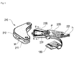
- a hard disc drive includes a magnetic disk 110 rotatably installed to a spindle motor (not shown) installed to base frame 100, a magnetic head actuator 200 rotated about a pivot shaft P to allow a magnetic head h to fly over the disk 110, and although not shown, a cover frame coupled to the base frame 100 to block inflow of a foreign substance and to protect the disk 110 and the magnetic head actuator 200.
- Reference numeral 120 denotes a circuit driving unit for performing signal transmission between a main circuit substrate (not shown) interfacing with a main apparatus such as a computer and the magnetic head h and for controlling the magnetic head actuator 200.
- the magnetic head actuator 200 includes a voice coil motor (VCM) 210 having lower and upper yokes 211 and 212 to which a pair of magnets M facing each other are attached, a swing arm 220 rotated about the pivot shaft P by the voice coil motor 210 as a head stack assembly (HAS), a suspension 230 supported by the swing arm 220 and having a front end to which the magnetic head h is installed, and a bobbin 230 branching off from the swing arm 220 to be positioned between the magnets M and on which the coil 231 is wound.
- VCM voice coil motor
- HAS head stack assembly
- the voice coil motor 210 which is a sort of driving motor for rotating the swing arm 220 to allow the magnetic head h to a desired position on the disk, utilizes Fleming's left hand rule, that is, a principle of generating force when current flows through a conductor in magnetic field.
- Fleming's left hand rule that is, a principle of generating force when current flows through a conductor in magnetic field.
- the voice coil motor 210 forces the bobbin 230 to be rotated.
- the swing arm 220 which branches off corresponding to the bobbin 230, is rotated, such that the magnetic head h supported on the end flies radially over the rotating disk 110 in order to search tracks to access data.
- the accessed data are processed by the circuit driving unit 120 and then, are recorded or output, for example, in or to a computer.
- the skin washing apparatus currently employs a rotation motor or a system of performing an arc screw reciprocating motion, the products are increased in size and the consumption power is increased, so that the battery lifetime is reduced.
- the present invention has been made in an effort to solve the above-described problems associated with the related art.
- the present invention provides an apparatus for washing skin using an electric motor and a spring which is capable of easily washing skin through a forward/rearward rotation and has a strong torque by using a spring force to allow a face-washing brush to press skin at a strong pressure, so that the skin washing efficiency is maximized, a method of controlling the same apparatus and a medium of recording a program for performing the same method.
- an apparatus for washing skin using a brushless electric motor and a spring includes a case (100); an operation unit (200) installed outside the case to generate a switching signal to allow the apparatus to be powered on or off and the brushless electric motor to be rotated forward and reward in units of a predetermined angle; a power supply unit (300) installed at one end inside the case; the brushless electric motor (400) installed inside the case to be operated by power applied from the power supply unit according to the switching signal from the operation unit, such that the brushless electric motor (400) is rotated in units of the predetermined angle; a control unit (500) to output an electric signal in order to control the forward and reward rotation of the brushless power at the predetermined angle according to the switching signal; a face-washing brush (600) fitted with a shaft of the brushless electric motor to be rotated forward and reverse as the brushless electric motor is operated; a holder (700) installed to the shaft of the brushless electric motor and including vertical
- the apparatus further includes a balance weight (1000) provided to an upper portion of the holder to absorb a vibration caused by the forward and reverse rotation of the holder.
- a balance weight 1000
- the spring (800) includes a coil spring or a leaf spring.
- the holder (700) includes a moving hole (710) through which the leaf spring slides.
- the control unit (500) includes a rectifying unit (510) including a rectifier (511) and a smoothing condenser (512) to rectify and smooth AC power in order to provide DC power; an inverter (530) to convert the DC power supplied from the rectifying unit (510) into three-phase AC power (U, V and W) in a pulse form having an arbitrary variable frequency and to supply the three-phase AC power to the brushless electric motor (400), the inverter including six switching devices (Q1 to Q6) and diodes; a terminal voltage detecting unit (560) to detect terminal voltages of each phase (U, V and W) from the three-phase AC power supplied to the brushless electric motor (400); a control circuit (570) to obtain information about a position of the rotor by detecting zero cross points of back electromotive force based on the terminal voltages of each phase (U, V and W) detected by the terminal voltage detecting unit (560), and to control a pattern of a PWM signal provided to the inverter (530) in order to
- a method of controlling an apparatus for washing skin using a brushless electric motor and a spring includes initially driving the brushless electric motor (400) when an operation unit outputs a switching signal (S10); detecting back electromagnetic force as a rotor is rotated during the initial driving of the brushless electric motor (400) (S20); outputting a PWM driving signal to forwardly rotate the rotor a predetermined angle based on a position of the rotor when the position of the rotor is detected (S30); and outputting a PWM signal to reversely rotate the rotor when the rotor is forwardly rotated at the predetermined angle set in the operation unit (S40).
- a computer readable recording medium of storing program codes to perform a method of controlling an apparatus for washing skin using a brushless electric motor and a spring includes a program code of initially driving the brushless electric motor (400) when an operation unit outputs a switching signal; a program code of detecting back electromagnetic force as a rotor is rotated during the initial driving of the brushless electric motor (400); a program code of outputting a PWM driving signal to forwardly rotate the rotor a predetermined angle based on a position of the rotor when the position of the rotor is detected; and a program code of outputting a PWM signal to reversely rotate the rotor when the rotor is forwardly rotated at the predetermined angle set in the operation unit.
- the skin washing operation is easily performed by rotating a face-washing brush in a forward/rearward direction using a rotational motor and a strong torque is provided by using a spring force to allow the face-washing brush to press a strong press skin at a strong pressure, so that the skin washing efficiency is maximized.
- FIG. 4 is a perspective view showing an entire configuration of the present invention.
- FIG. 5 is a longitudinal sectional view taken along line A-A of FIG. 4 .
- FIG. 6 is a perspective view showing main parts of an electric motor, a spring, and a support according to the embodiment of the present invention.
- FIG. 7 is an exploded perspective view of FIG. 6 .
- FIG. 8 is a partially cutaway view of FIG. 6 .
- FIG. 9 is a view showing an operation of moving the spring according to the embodiment of the present invention leftward and rightward.
- a skin washing apparatus includes a case 100, an operation unit 200, a power supply unit 300, a brushless electric motor 400, a control unit 500, a skin washing brush 600, a holder 700, a leaf spring 800, a support 900, and a balance weight 1000.
- the case 100 has an external appearance that can be gripped by a hand.
- the power supply unit 300 and the brushless electric motor 400 are received in the case 100 and the operation unit 200 is disposed outside the case 100.
- the operation unit 200 is installed outside the case 100, and is configured in the type of a toggle or a push button to enable the brushless electric motor 400 to be powered on or off and to be rotated forward/reverse in units of a predetermined angle and to induce the brushless electric motor 400 to be rotated forward and reverse within a necessary angle range.
- the power supply unit 300 is installed within the case 100, and serves to supply electric power to the apparatus.
- the power supply unit 300 may use a battery or a rechargeable battery, and may be connected to an external power source through a cable to receive electric power through the cable.
- the brushless electric motor 400 is installed within the case, and is operated by the electric power applied from the power supply unit 300 according to a switching signal of the operation unit 200 and is rotated forward and reverse in units of a predetermined angle.
- the control unit 500 detects a counter electromotive force of the brushless electric motor 400 to recognize a position of the rotor, and outputs an electrical signal for controlling the forward/reverse rotation of the brushless electric motor 400 at a predetermined angle according to the switching signal of the operation unit 200.
- the skin washing brush 600 is fitted with the shaft of the brushless electric motor 400 and is rotated forwardly and reversely according to an operation of the brushless electric motor 400 to wash a face of the user.
- the holder 700 is connected to the shaft 410 of the brushless electric motor 400, and is L-shaped to include a vertical panel 700a and a horizontal panel 700b. The holder 700 is rotated forwardly and reversely according to the forward/reverse rotation of the brushless electric motor 400.
- the spring 800 is coupled to a bottom surface of the horizontal panel of the holder 700 and an opposite side of the spring 800 is coupled to the support 900, such that the spring 800 is moved about the support 900 to provide resiliency to the support 900 to generate a torque to an original location when the holder 700 is moved vertically, upward and downward.
- the spring 800 is a leaf spring having a rectangular panel shape. That is, a coil spring may be employed as the spring 800 if necessary, but a plate spring may be employed for a stronger instantaneous torque. When a plate spring is applied, a movement hole 710 is formed in the holder 700 such that the spring 800 is slid and moved more easily in left and right directions.
- the balance weight 1000 is coupled to an upper portion of the holder 700 to absorb the vibration caused by the forward/reverse rotation of the holder 700.
- the brushless electric motor (BLDC motor) 400 applied to the present invention essentially includes a stator generating a rotating magnetic field that is rotated spatially, and a rotor in which a permanent magnet is embedded and which is synchronized with a rotating speed of the rotational magnetic field to be rotated relatively, and includes a separate control unit for controlling the rotations of the motor.
- the stator of the BLDC motor employs an armature in which a current flows through a three-phase coil, and the rotor employs a permanent magnet in which the N pole and the S pole are repeated.
- a continuous rotating magnetic field should be formed in the BLDC motor, and in order to form the continuous rotating magnetic field, the currents flowing in the phases of the armature should be commutated at a certain time point.
- the rotor position should be accurately recognized for proper commutation.
- commutation refers to a change of a current direction of the motor stator coil to rotate the rotor.
- the rotor position and the phase current should be accurately synchronized with each other.
- a device for detecting the position of the rotor is required.
- hall sensors each of which generates a voltage varied according to a variation of magnetic flux, or CTs (Current Transformers), which are installed on each phase of the rotor, may be used to detect the rotor position.
- CTs Current Transformers
- a control unit 500 includes position sensors (not shown) which are placed between three (U, V and W) phases for sensing the relative position of the rotor with respect to the stator, a rectifier circuit 510 for converting AC power to DC power, a smoothing condenser 520 for removing voltage ripple components from the converted DC power, an inverter circuit 530 which includes a plurality of electric power devices to apply an AC voltage corresponding to a desired average voltage and a frequency to the motor according to switching states of the power devices by selectively providing the DC voltage from the smoothing condenser 520 to the motor, a control circuit 540 for controlling the inverter circuit 530 based on sensed values of the position sensors, and a power circuit 550 for supplying power to the control circuit 540.
- Reference numeral '1' that is not described in this specification, is a BLDC motor (hereinafter, referred to as "motor”) expressed as an equivalent circuit.
- the three position sensors (Sa, Sb and Sc) located between the three (U, V and W) phases of the motor 400 outputs sensed values every 60 electrical degrees as the rotor is rotated.
- the power devices of the inverter circuit 530 are switched according to PWM signals generated from the control circuit 540 based on the sensed values, so that the motor 400 is driven by allowing phase current to flow through two of three (U, V and W) phases, so EMF (Electromotive Force) induced to each phase is generated for 120 electrical degrees.
- a scheme of detecting the rotor position using a current transformer (CT) is the most ideal control scheme in which a coordinate conversion is performed to resolve the phase currents obtained from each phase into d (direct) axis and q (quadrature) axis components, so that the phase currents is divided into field current and armature current like a brushed DC motor.
- CT current transformer
- the detection of using a back EMF is achieved by detecting a magnet position inside a rotor based on an EMF generated from one of three phase coils of the motor when the magnetic field is varied as current is provided to the other two phase coils to rotate the rotor.
- the EMF is obtained in a trapezoidal form.
- the motor is controlled by providing current at the time points that the phase angle is delayed at 30 degrees after the ZCP (Zero Cross Point), at which the EMF is zero, is detected.
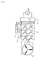
- the apparatus for senselessly driving a BLDC motor includes an amplifying unit 510, an inverter 530, a terminal voltage detecting unit 560, a control circuit 570 and a PWM signal generating unit 580.
- the rectifying unit 510 which rectifies and smoothies AC power in order to provide DC power, includes a rectifier 511 and a smoothing condenser 512.
- the inverter 530 converts the DC power supplied from the rectifying unit 510 into three-phase AC power (U, V and W) in a pulse form having an arbitrary variable frequency and supplies the three-phase AC power.
- the inverter 530 which is a conventional switching circuit, includes six switching devices Q1 to Q6 and diodes.
- the terminal voltage detecting unit 560 detects terminal voltages of each phase (U, V and W) from the three-phase AC power supplied to the BLDC motor 400 and inputs the detection result to the control circuits 570.
- the control circuit 570 which is a microprocessor of controlling a pattern of a PWM signal provided to the inverter 530, obtains information about a position of the rotor by detecting ZCPs of the back EMF based on the terminal voltages of each phase detected by the terminal voltage detecting unit 560.
- the control circuit 570 executes the entire inverter control algorithm.
- the PWM signal generating unit 580 generates a pattern of a PWM signal under the control of the control circuit 570 and provides the PWM signal pattern to the inverter 530.
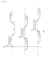
- FIG. 14 is graphs of a signal output from the control unit and a voltage applied to the motor to rotate the rotor clockwise and counter-clockwise according to the embodiment of the present invention.
- the rotor position of the BLDC motor 400 is detected to achieve perfect control without any torque ripples.
- the voltage and current are made in the form of a sinusoidal wave.
- an initial driving algorithm is required.
- the initial driving algorithm which is used to control the BLDC motor 400 is well known in the art. Since a forced alignment scheme, which is generally known in the art, is used in the present invention, the detailed description will be omitted.
- a PWM control scheme which is the same as the sinusoidal wave control scheme for an AC induction motor, is used as a driving scheme. Only, various schemes such as a triangular wave scheme or a circle approximation scheme may be applied for a carrier frequency.
- the ZCPs of the induced EMFs generated at each phase are detected and PWM signals generated based on the information about the ZCPs are output. After this time, since the motor is driven through three phase conduction current, the current has a sinusoidal waveform.
- control circuit is programmed to allow the motor 400 to be rotated clockwise and counter-clockwise, so that the face-washing brush 600 vibrates.
- the rotor of the BLDC motor 400 is rotated clockwise at a predetermined angle and the rotor is rotated counter-clockwise after check the rotor position using the induced EMF.
- the face-washing brush 600 repeats the forward/reverse rotation.
- the spring 800 is coupled to the holder 700 of the BLDC motor 400, the spring 800 is modified as the holder 700 is rotated forwardly and reversely.
- the spring 800 is made of a material having an elastic restoring force, the motor 400, if the spring 800 is bent as the holder 700 is rotated by the rotation of the motor 400, the restoring force of the holder 700 is maximized while a strong torque is generated at the time that the rotation of the motor 400 is completed.
- the face-washing brush 600 is very rapidly rotated forwardly and reversely.
- the electric motor 400 is operated while the electric motor 400 quickly turns the forward and reverse rotation direction, the strong torque is applied to the face-washing brush 600, so that the face-washing is performed at a strong force.
- Program codes of a control circuit for rotating the rotor of the electric motor 400 forward and reverse at the predetermined angle may be stored in various storing devices and may be input to the control circuit to driving the electric motor 400.
- the computer-readable recording media include a ROM, a RAM, a CD-ROM, a magnetic table, a floppy disk, and an optical data storing device, and include a device realized in the form of a carrier wave (for example, transmission over the Internet).
- the computer-readable recording media are distributed into computer systems connected to each other through a network to store computer-readable codes through a distribution scheme so that the computer-readable codes may be executed.
- function programs, codes, and code segments used to realize the method can be easily deduced by programmers in the art to which the disclosure pertains.
- the brushless electric motor is used and the operation mode of the brushless electric motor is set to rotate the rotor of the brushless electric motor forward and reverse at the predetermined angle.
- a strong torque is generated by the spring force, so that the facing washing is perfectly and conventionally performed.
Landscapes
- Health & Medical Sciences (AREA)
- Public Health (AREA)
- General Health & Medical Sciences (AREA)
- Epidemiology (AREA)
- Engineering & Computer Science (AREA)
- Rehabilitation Therapy (AREA)
- Animal Behavior & Ethology (AREA)
- Life Sciences & Earth Sciences (AREA)
- Physical Education & Sports Medicine (AREA)
- Veterinary Medicine (AREA)
- Pain & Pain Management (AREA)
- Mechanical Engineering (AREA)
- Power Engineering (AREA)
- Dermatology (AREA)
- Control Of Motors That Do Not Use Commutators (AREA)
- Body Washing Hand Wipes And Brushes (AREA)
Abstract
Description
- The present invention relates to an apparatus for washing skin using an electric motor and a spring, a method of controlling the same apparatus and a medium of recording a program for performing the same method. More particularly, the present invention relates to a skin washing apparatus in which a vibration is made by a forward/rearward rotation through an interaction between a motor and a leaf spring to optimally wash a skin while the current consumption is minimized, a method of controlling the same apparatus and a medium recording a program for performing the same method.
- In general, everybody wants to obtain beauty of their body. To pursue the beauty of one's body, specifically skin, skin is kept clean and a systematic skin management is required. To this end, a skin management apparatus has be developed and used. In addition, various types of skin manage apparatus are developed and used to meet the characteristics of each part of body.
- Specifically, a most basic method of managing the treatment of facial skin among parts of body is to teat facial skin using cosmetics. Currently, functional cosmetics have been mainly used as the cosmetics for managing a skin treatment.
- Meanwhile, various apparatus for washing a face have been proposed until now. Two-type vibration schemes have been mostly applied to rotate a washing brush, one of which is to simply make rotation and the other is to generate a vibration.
- Since the scheme of rotating a washing brush through the simple rotation of a motor is very general, the detailed description will be omitted. Hereinafter a method of applying an eccentric disc and a basic concept of a motor rotated in a circular screw motion will be described in brief.
- First, a general eccentrically rotatable vibration motor is depicted in
FIG. 1 . As shown inFIG. 1 , aPCB mounting unit 1 may be formed in alower case 2. Apermanent magnet 3 is fixed to an upper portion of thelower case 2. Arotor 7 is rotatably installed on thepermanent magnet 3, which serves as a stator, with a predetermined gap between them. Therotor 7 includes acoil 8 and asegment 9 such that therotor 7 is eccentric as a whole. In addition, therotor 7 itself has the mass center eccentric to one side, so that therotor 7 itself is operated as the eccentric mass. - To allow the rotor of the vibration motor to be rotated in a predetermined direction, a rectifier circuit, which exchanges the coils to which current is provided, is required. A current circuit of a coin type vibration motor includes a
brush 5 electrically connected to a PCB circuit of aPCB circuit substrate 6 andsegments 9. When reviewing the rotation principle of the coin type vibration motor, the DC power input from thePCB circuit 4 is provided to a coil part through thesegments 9 making contact with thebrush 5. In this case, since the segments 99 making contact with thebrush 5 are exchanged by the rotating rotor, the rectification is achieved. - Second, there is a vibration scheme of employing a voice coil which is the most applied to a hard disc drive, so the vibration scheme of employing a voice coil will be described in brief with reference the hard disc drive. As shown in
FIG. 2 , a hard disc drive includes amagnetic disk 110 rotatably installed to a spindle motor (not shown) installed tobase frame 100, amagnetic head actuator 200 rotated about a pivot shaft P to allow a magnetic head h to fly over thedisk 110, and although not shown, a cover frame coupled to thebase frame 100 to block inflow of a foreign substance and to protect thedisk 110 and themagnetic head actuator 200.Reference numeral 120 denotes a circuit driving unit for performing signal transmission between a main circuit substrate (not shown) interfacing with a main apparatus such as a computer and the magnetic head h and for controlling themagnetic head actuator 200. - As shown in
FIG. 3 , themagnetic head actuator 200 includes a voice coil motor (VCM) 210 having lower andupper yokes swing arm 220 rotated about the pivot shaft P by thevoice coil motor 210 as a head stack assembly (HAS), asuspension 230 supported by theswing arm 220 and having a front end to which the magnetic head h is installed, and abobbin 230 branching off from theswing arm 220 to be positioned between the magnets M and on which thecoil 231 is wound. - The
voice coil motor 210, which is a sort of driving motor for rotating theswing arm 220 to allow the magnetic head h to a desired position on the disk, utilizes Fleming's left hand rule, that is, a principle of generating force when current flows through a conductor in magnetic field. Thus, when current is applied to thecoil 231 positioned between the magnets M, thevoice coil motor 210 forces thebobbin 230 to be rotated. Thus, theswing arm 220, which branches off corresponding to thebobbin 230, is rotated, such that the magnetic head h supported on the end flies radially over the rotatingdisk 110 in order to search tracks to access data. Then, the accessed data are processed by thecircuit driving unit 120 and then, are recorded or output, for example, in or to a computer. - Meanwhile, although the skin washing apparatus currently employs a rotation motor or a system of performing an arc screw reciprocating motion, the products are increased in size and the consumption power is increased, so that the battery lifetime is reduced.
- In addition, direction in the related art, since the motor is rotated in a unique and a cleaning solution is coated on a face while the skin washing brush is rotated in the unique direction, it is difficult to allow the cleaning solution to make uniform contact with the face.
- The present invention has been made in an effort to solve the above-described problems associated with the related art. The present invention provides an apparatus for washing skin using an electric motor and a spring which is capable of easily washing skin through a forward/rearward rotation and has a strong torque by using a spring force to allow a face-washing brush to press skin at a strong pressure, so that the skin washing efficiency is maximized, a method of controlling the same apparatus and a medium of recording a program for performing the same method.
- To achieve the object, according to one aspect of the present invention, there is provided an apparatus for washing skin using a brushless electric motor and a spring. The apparatus includes a case (100); an operation unit (200) installed outside the case to generate a switching signal to allow the apparatus to be powered on or off and the brushless electric motor to be rotated forward and reward in units of a predetermined angle; a power supply unit (300) installed at one end inside the case; the brushless electric motor (400) installed inside the case to be operated by power applied from the power supply unit according to the switching signal from the operation unit, such that the brushless electric motor (400) is rotated in units of the predetermined angle; a control unit (500) to output an electric signal in order to control the forward and reward rotation of the brushless power at the predetermined angle according to the switching signal; a face-washing brush (600) fitted with a shaft of the brushless electric motor to be rotated forward and reverse as the brushless electric motor is operated; a holder (700) installed to the shaft of the brushless electric motor and including vertical and horizontal panels bent in a L-shape, wherein the holder is rotated forward and reverse as the brushless electric motor is rotated forward and reverse; a spring (800) including one side coupled to the horizontal panel of the holder and an opposite side coupled to a support, wherein the spring moves along the support to generate a torque toward an original position by an elastic property as the holder moves upward and downward in a vertical direction; and the support (900) to support the opposite side of the spring.
- The apparatus further includes a balance weight (1000) provided to an upper portion of the holder to absorb a vibration caused by the forward and reverse rotation of the holder.
- The spring (800) includes a coil spring or a leaf spring.
- The holder (700) includes a moving hole (710) through which the leaf spring slides.
- The control unit (500) includes a rectifying unit (510) including a rectifier (511) and a smoothing condenser (512) to rectify and smooth AC power in order to provide DC power; an inverter (530) to convert the DC power supplied from the rectifying unit (510) into three-phase AC power (U, V and W) in a pulse form having an arbitrary variable frequency and to supply the three-phase AC power to the brushless electric motor (400), the inverter including six switching devices (Q1 to Q6) and diodes; a terminal voltage detecting unit (560) to detect terminal voltages of each phase (U, V and W) from the three-phase AC power supplied to the brushless electric motor (400); a control circuit (570) to obtain information about a position of the rotor by detecting zero cross points of back electromotive force based on the terminal voltages of each phase (U, V and W) detected by the terminal voltage detecting unit (560), and to control a pattern of a PWM signal provided to the inverter (530) in order to allow a rotor of the brushless electric motor to be rotated forward and reverse at the predetermined angle; and a PWM signal generating unit (580) to generate the pattern of the PWM signal under control of the control circuit (570) and provides the pattern of the PWM signal to the inverter (530).
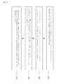
- According to another aspect of the present invention, there is provided a method of controlling an apparatus for washing skin using a brushless electric motor and a spring. The method includes initially driving the brushless electric motor (400) when an operation unit outputs a switching signal (S10); detecting back electromagnetic force as a rotor is rotated during the initial driving of the brushless electric motor (400) (S20); outputting a PWM driving signal to forwardly rotate the rotor a predetermined angle based on a position of the rotor when the position of the rotor is detected (S30); and outputting a PWM signal to reversely rotate the rotor when the rotor is forwardly rotated at the predetermined angle set in the operation unit (S40).
- According to still another aspect of the present invention, there is provided a computer readable recording medium of storing program codes to perform a method of controlling an apparatus for washing skin using a brushless electric motor and a spring. The program codes includes a program code of initially driving the brushless electric motor (400) when an operation unit outputs a switching signal; a program code of detecting back electromagnetic force as a rotor is rotated during the initial driving of the brushless electric motor (400); a program code of outputting a PWM driving signal to forwardly rotate the rotor a predetermined angle based on a position of the rotor when the position of the rotor is detected; and a program code of outputting a PWM signal to reversely rotate the rotor when the rotor is forwardly rotated at the predetermined angle set in the operation unit.
- According to the present invention, the skin washing operation is easily performed by rotating a face-washing brush in a forward/rearward direction using a rotational motor and a strong torque is provided by using a spring force to allow the face-washing brush to press a strong press skin at a strong pressure, so that the skin washing efficiency is maximized.
-
-
FIG. 1 is a view showing a general eccentrically rotatable vibration motor; -
FIG. 2 is a view showing a hard disk drive employing a voice coil; -
FIG. 3 is a view showing an operation of an actuator employing a voice coil; -
FIG. 4 is a perspective view showing a skin washing apparatus according to an embodiment of the present invention; -
FIG. 5 is a longitudinal sectional view taken along line A-A ofFIG. 4 ; -
FIG. 6 is a perspective view showing main parts of an electric motor, a spring, and a support according to the embodiment of the present invention; -
FIG. 7 is an exploded perspective view ofFIG. 6 ; -
FIG. 8 is a partially cutaway view ofFIG. 6 ; -
FIG. 9 is a view showing an operation of the spring according to the embodiment of the present invention; -
FIG. 10 is a circuit diagram of a control unit according to a first embodiment of the present invention; -
FIGS. 11A and 11B show detection of positions using a CT and a 180 degree sine wave control pattern diagram according to the first embodiment of the present invention; -
FIGS. 12A and12b are detection of positions using a counter electromotive force and a 120 degree square wave control pattern diagram according to the first embodiment of the present invention; -
FIG. 13 is a circuit diagram of a control unit according to a second embodiment of the present invention; -
FIG. 14 is a graph depicting output signals of a control unit for rotating a rotor clockwise and counterclockwise and motor voltages according to the second embodiment of the present invention; and -
FIG. 15 is a flowchart showing a control operation according to an embodiment of the present invention. - Hereinafter, an operation principle of exemplary embodiments of the present invention will be described in detail with reference to the accompanying drawings. However, the drawings and the description thereof correspond to exemplary embodiments of the present invention among various methods for effectively describing the features of the present invention, and the present invention is not limited to the drawings and description.
- In the following description of the present invention, a detailed description of known functions and configurations incorporated herein will be omitted when it may make the subject matter of the present invention rather unclear. Further, the following terms are those defined, considering the functions of the present invention, and may be changed according to the intentions of the user or the manager or the customs. Therefore, the definitions of the terms should be made based on the contents of the specification.
- Here, in the description of the embodiments of the present invention, in order to effectively describe the technical elements of the present invention, system elements that are included in a functional configuration of the system or conventionally provided in the technical field of the present invention will be omitted and functional elements that should be additionally provided for the present invention will be mainly described.
- Those skilled in the art to which the present invention pertains can understand functions of conventionally used constituent elements that are not illustrated but omitted, and also can clearly understand the relationships between the omitted elements and the added elements of the present invention.
- In the embodiments of the present invention, the terms will be properly modified to effectively describe the technical features of the present invention so that those skilled in the art can clearly understand the present invention, but the present invention is not limited to the embodiments.
- As a result, the spirit of the present invention is determined by the claims, and the embodiments of the present invention are merely means for effectively describing the spirit of the present invention to those skilled in the art.
-
FIG. 4 is a perspective view showing an entire configuration of the present invention. -
FIG. 5 is a longitudinal sectional view taken along line A-A ofFIG. 4 . -
FIG. 6 is a perspective view showing main parts of an electric motor, a spring, and a support according to the embodiment of the present invention. -
FIG. 7 is an exploded perspective view ofFIG. 6 . -
FIG. 8 is a partially cutaway view ofFIG. 6 . -
FIG. 9 is a view showing an operation of moving the spring according to the embodiment of the present invention leftward and rightward. - A skin washing apparatus according to the embodiment of the present invention includes a
case 100, anoperation unit 200, apower supply unit 300, a brushlesselectric motor 400, a control unit 500, askin washing brush 600, aholder 700, aleaf spring 800, asupport 900, and abalance weight 1000. - The
case 100 has an external appearance that can be gripped by a hand. Thepower supply unit 300 and the brushlesselectric motor 400 are received in thecase 100 and theoperation unit 200 is disposed outside thecase 100. - The
operation unit 200 is installed outside thecase 100, and is configured in the type of a toggle or a push button to enable the brushlesselectric motor 400 to be powered on or off and to be rotated forward/reverse in units of a predetermined angle and to induce the brushlesselectric motor 400 to be rotated forward and reverse within a necessary angle range. - The
power supply unit 300 is installed within thecase 100, and serves to supply electric power to the apparatus. Thepower supply unit 300 may use a battery or a rechargeable battery, and may be connected to an external power source through a cable to receive electric power through the cable. - The brushless
electric motor 400 is installed within the case, and is operated by the electric power applied from thepower supply unit 300 according to a switching signal of theoperation unit 200 and is rotated forward and reverse in units of a predetermined angle. - The control unit 500 detects a counter electromotive force of the brushless
electric motor 400 to recognize a position of the rotor, and outputs an electrical signal for controlling the forward/reverse rotation of the brushlesselectric motor 400 at a predetermined angle according to the switching signal of theoperation unit 200. - The
skin washing brush 600 is fitted with the shaft of the brushlesselectric motor 400 and is rotated forwardly and reversely according to an operation of the brushlesselectric motor 400 to wash a face of the user. - The
holder 700 is connected to theshaft 410 of the brushlesselectric motor 400, and is L-shaped to include avertical panel 700a and ahorizontal panel 700b. Theholder 700 is rotated forwardly and reversely according to the forward/reverse rotation of the brushlesselectric motor 400. - One side of the
spring 800 is coupled to a bottom surface of the horizontal panel of theholder 700 and an opposite side of thespring 800 is coupled to thesupport 900, such that thespring 800 is moved about thesupport 900 to provide resiliency to thesupport 900 to generate a torque to an original location when theholder 700 is moved vertically, upward and downward. Preferably, thespring 800 is a leaf spring having a rectangular panel shape. That is, a coil spring may be employed as thespring 800 if necessary, but a plate spring may be employed for a stronger instantaneous torque. When a plate spring is applied, amovement hole 710 is formed in theholder 700 such that thespring 800 is slid and moved more easily in left and right directions. - The
balance weight 1000 is coupled to an upper portion of theholder 700 to absorb the vibration caused by the forward/reverse rotation of theholder 700. - The brushless electric motor (BLDC motor) 400 applied to the present invention essentially includes a stator generating a rotating magnetic field that is rotated spatially, and a rotor in which a permanent magnet is embedded and which is synchronized with a rotating speed of the rotational magnetic field to be rotated relatively, and includes a separate control unit for controlling the rotations of the motor.
- That is, the stator of the BLDC motor employs an armature in which a current flows through a three-phase coil, and the rotor employs a permanent magnet in which the N pole and the S pole are repeated. In order that the BLDC motor is rotated continuously, a continuous rotating magnetic field should be formed in the BLDC motor, and in order to form the continuous rotating magnetic field, the currents flowing in the phases of the armature should be commutated at a certain time point. The rotor position should be accurately recognized for proper commutation. Here, commutation refers to a change of a current direction of the motor stator coil to rotate the rotor.
- To smoothly operate the BLDC motor, the rotor position and the phase current should be accurately synchronized with each other. To this end, a device for detecting the position of the rotor is required. Thus, hall sensors, each of which generates a voltage varied according to a variation of magnetic flux, or CTs (Current Transformers), which are installed on each phase of the rotor, may be used to detect the rotor position.
- As shown in
FIG. 10 , a control unit 500 includes position sensors (not shown) which are placed between three (U, V and W) phases for sensing the relative position of the rotor with respect to the stator, arectifier circuit 510 for converting AC power to DC power, a smoothingcondenser 520 for removing voltage ripple components from the converted DC power, aninverter circuit 530 which includes a plurality of electric power devices to apply an AC voltage corresponding to a desired average voltage and a frequency to the motor according to switching states of the power devices by selectively providing the DC voltage from the smoothingcondenser 520 to the motor, acontrol circuit 540 for controlling theinverter circuit 530 based on sensed values of the position sensors, and apower circuit 550 for supplying power to thecontrol circuit 540. Reference numeral '1', that is not described in this specification, is a BLDC motor (hereinafter, referred to as "motor") expressed as an equivalent circuit. - The three position sensors (Sa, Sb and Sc) located between the three (U, V and W) phases of the
motor 400 outputs sensed values every 60 electrical degrees as the rotor is rotated. The power devices of theinverter circuit 530 are switched according to PWM signals generated from thecontrol circuit 540 based on the sensed values, so that themotor 400 is driven by allowing phase current to flow through two of three (U, V and W) phases, so EMF (Electromotive Force) induced to each phase is generated for 120 electrical degrees. - Meanwhile, when the motor employs the hole sensors, since it is impossible to installed the hole sensors to the motor operated under high-temperature and high pressure environment, so that the motor employing the hole sensors is not used to driving a compressor.
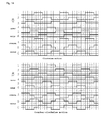
- To the contrary, a scheme of detecting the rotor position using a current transformer (CT) is the most ideal control scheme in which a coordinate conversion is performed to resolve the phase currents obtained from each phase into d (direct) axis and q (quadrature) axis components, so that the phase currents is divided into field current and armature current like a brushed DC motor. For this reason, this is a vector control scheme of obtaining a desired torque through a current control. As shown in
FIG. 11a , the voltages applied to each phase are in a PWM type and the current waveforms are in a form of a sinusoidal wave. As shown inFIG. 11b , current flows through all of the three-phase coils of the BLDC motor, so the phase efficiency is improved. - Thus, since 180 degrees conduction current control may be performed through the position detection using CT and a back EMF and current have a form of a sinusoidal wave, as a result, a torque ripple is not generated, so that the scheme is good in efficiency and torque, noise and vibration characteristics. However, this scheme uses an expensive CT, requires significant technology to construct a dedicated vector control algorithm, and is attendant on many trials and errors. In addition, the cost of the control is increased due to a complicate control algorithm, and the overall high technology and the fabrication cost become burdened.
- To solve the problems, search for a scheme of detecting a rotor position using an electric circuit has been performed. As the result, a scheme of detecting a rotor position using a back electromotive force of a BLDC motor has been widely used.
- As shown in
FIG. 12b , the detection of using a back EMF is achieved by detecting a magnet position inside a rotor based on an EMF generated from one of three phase coils of the motor when the magnetic field is varied as current is provided to the other two phase coils to rotate the rotor. In this case, as shown inFIG. 12a , the EMF is obtained in a trapezoidal form. The motor is controlled by providing current at the time points that the phase angle is delayed at 30 degrees after the ZCP (Zero Cross Point), at which the EMF is zero, is detected. - Referring to
FIG. 13 , the apparatus for senselessly driving a BLDC motor includes anamplifying unit 510, aninverter 530, a terminal voltage detecting unit 560, acontrol circuit 570 and a PWMsignal generating unit 580. - The rectifying
unit 510, which rectifies and smoothies AC power in order to provide DC power, includes arectifier 511 and a smoothingcondenser 512. - The
inverter 530 converts the DC power supplied from the rectifyingunit 510 into three-phase AC power (U, V and W) in a pulse form having an arbitrary variable frequency and supplies the three-phase AC power. Theinverter 530, which is a conventional switching circuit, includes six switching devices Q1 to Q6 and diodes. - The terminal voltage detecting unit 560 detects terminal voltages of each phase (U, V and W) from the three-phase AC power supplied to the
BLDC motor 400 and inputs the detection result to thecontrol circuits 570. - The
control circuit 570, which is a microprocessor of controlling a pattern of a PWM signal provided to theinverter 530, obtains information about a position of the rotor by detecting ZCPs of the back EMF based on the terminal voltages of each phase detected by the terminal voltage detecting unit 560. Thecontrol circuit 570 executes the entire inverter control algorithm. - The PWM
signal generating unit 580 generates a pattern of a PWM signal under the control of thecontrol circuit 570 and provides the PWM signal pattern to theinverter 530. -
FIG. 14 is graphs of a signal output from the control unit and a voltage applied to the motor to rotate the rotor clockwise and counter-clockwise according to the embodiment of the present invention. - Hereinafter a process of controlling a BLDC motor in the above described configuration according to the embodiment of the present invention and operation effect thereof will be described.
- According to the present invention, the rotor position of the
BLDC motor 400 is detected to achieve perfect control without any torque ripples. To this end, the voltage and current are made in the form of a sinusoidal wave. Even though any control schemes are used to drive theBLDC motor 400, since it is not known at the initial stage where the magnet of the rotor is positioned, an initial driving algorithm is required. Even in this case, since the induced EMF is obtained after the rotor is first rotated, a separated initial driving algorithm is likewise required. The initial driving algorithm which is used to control theBLDC motor 400 is well known in the art. Since a forced alignment scheme, which is generally known in the art, is used in the present invention, the detailed description will be omitted. - Thus, when an initial magnet position of the rotor is obtained, the rotor is synchronized and rotated in a predetermined sequence until the rotation arrives at a predetermined speed, so that induced EMF is generated. After this section, the sinusoidal wave control starts. A PWM control scheme, which is the same as the sinusoidal wave control scheme for an AC induction motor, is used as a driving scheme. Only, various schemes such as a triangular wave scheme or a circle approximation scheme may be applied for a carrier frequency.
- As the rotor is rotated, the ZCPs of the induced EMFs generated at each phase are detected and PWM signals generated based on the information about the ZCPs are output. After this time, since the motor is driven through three phase conduction current, the current has a sinusoidal waveform.
- In this case, there is an advantage when distribution windings are used as the windings of the
BLDC motor 400 in order to easily detect the ZCPs. - Hereinafter, the entire operation of the present invention will be described with reference to
FIG. 15 . - When a power switch is switched on by a user, the electric motor is operated.
- According to the present invention, the control circuit is programmed to allow the
motor 400 to be rotated clockwise and counter-clockwise, so that the face-washing brush 600 vibrates. - That is, the rotor of the
BLDC motor 400 is rotated clockwise at a predetermined angle and the rotor is rotated counter-clockwise after check the rotor position using the induced EMF. Thus, by rotating the rotor clockwise and counter-clockwise, the face-washing brush 600 repeats the forward/reverse rotation. - In this case, since the
spring 800 is coupled to theholder 700 of theBLDC motor 400, thespring 800 is modified as theholder 700 is rotated forwardly and reversely. - That is, when the
holder 700 is rotated clockwise, thespring 800 is bent clockwise. When theholder 700 is rotated counter-clockwise, thespring 800 is bent counter-clockwise. - Since the
spring 800 is made of a material having an elastic restoring force, themotor 400, if thespring 800 is bent as theholder 700 is rotated by the rotation of themotor 400, the restoring force of theholder 700 is maximized while a strong torque is generated at the time that the rotation of themotor 400 is completed. - Thus, the face-
washing brush 600 is very rapidly rotated forwardly and reversely. - In a state that the
electric motor 400 is rotated forward at the predetermined angle so that thespring 800 is bent at the maximum, if the electric motor starts to be reversely rotated, the restoring force of thespring 800 is added to the torque of theelectric motor 400, so that theelectric motor 400 is more quickly rotated. Since thespring 800 is bent at the maximum in an opposite direction after thespring 800 returns to the original position at the time that the reverse rotation is completed, the rotation direction of theelectric motor 400 is quickly changed in the forward direction while the maximum torque is applied to theelectric motor 400 at the moment that the rotation direction is changed. - As described above, since the
electric motor 400 is operated while theelectric motor 400 quickly turns the forward and reverse rotation direction, the strong torque is applied to the face-washing brush 600, so that the face-washing is performed at a strong force. - Program codes of a control circuit for rotating the rotor of the
electric motor 400 forward and reverse at the predetermined angle may be stored in various storing devices and may be input to the control circuit to driving theelectric motor 400. The computer-readable recording media include a ROM, a RAM, a CD-ROM, a magnetic table, a floppy disk, and an optical data storing device, and include a device realized in the form of a carrier wave (for example, transmission over the Internet). The computer-readable recording media are distributed into computer systems connected to each other through a network to store computer-readable codes through a distribution scheme so that the computer-readable codes may be executed. In addition, function programs, codes, and code segments used to realize the method can be easily deduced by programmers in the art to which the disclosure pertains. - Therefore, according to the present invention, the brushless electric motor is used and the operation mode of the brushless electric motor is set to rotate the rotor of the brushless electric motor forward and reverse at the predetermined angle. In addition, a strong torque is generated by the spring force, so that the facing washing is perfectly and conventionally performed.
-
- 100: case of an apparatus for washing skin
- 200: operation unit
- 300: power supply unit
- 400: brushless electric motor
- 500: control unit
- 510: rectifying unit
- 520: smoothing condenser
- 530: inverter
- 540: control circuit
- 550: Power circuit
- 560: terminal voltage detecting unit
- 570: control circuit
- 580: PWM signal generating unit
- 600: face-washing brush
- 700: holder
- 800: spring
- 900: support
- 1000: balance weight
Claims (7)
- An apparatus for washing skin using a brushless electric motor and a spring, the apparatus comprising:a case (100);an operation unit (200) installed outside the case to generate a switching signal to allow the apparatus to be powered on or off and the brushless electric motor to be rotated forward and reward in units of a predetermined angle;a power supply unit (300) installed at one end inside the case;the brushless electric motor (400) installed inside the case to be operated by power applied from the power supply unit according to the switching signal from the operation unit, such that the brushless electric motor (400) is rotated in units of the predetermined angle;a control unit (500) to output an electric signal in order to control the forward and reward rotation of the brushless power at the predetermined angle according to the switching signal;a face-washing brush (600) fitted with a shaft of the brushless electric motor to be rotated forward and reverse as the brushless electric motor is operated;a holder (700) installed to the shaft of the brushless electric motor and including vertical and horizontal panels bent in a L-shape, wherein the holder is rotated forward and reverse as the brushless electric motor is rotated forward and reverse;a spring (800) including one side coupled to the horizontal panel of the holder and an opposite side coupled to a support, wherein the spring moves along the support to generate a torque toward an original position by an elastic property as the holder moves upward and downward in a vertical direction; andthe support (900) to support the opposite side of the spring.
- The apparatus of claim 1, further comprising a balance weight (1000) provided to an upper portion of the holder to absorb a vibration caused by the forward and reverse rotation of the holder.
- The apparatus of claim 1, wherein the spring (800) includes a coil spring or a leaf spring.
- The apparatus of claim 3, wherein the holder (700) includes a moving hole (710) through which the leaf spring slides.
- The apparatus of claim 1, wherein the control unit (500) includes a rectifying unit (510) including a rectifier (511) and a smoothing condenser (512) to rectify and smooth AC power in order to provide DC power;
an inverter (530) to convert the DC power supplied from the rectifying unit (510) into three-phase AC power (U, V and W) in a pulse form having an arbitrary variable frequency and to supply the three-phase AC power to the brushless electric motor (400), the inverter including six switching devices (Q1 to Q6) and diodes;
a terminal voltage detecting unit (560) to detect terminal voltages of each phase (U, V and W) from the three-phase AC power supplied to the brushless electric motor (400);
a control circuit (570) to obtain information about a position of the rotor by detecting zero cross points of back electromotive force based on the terminal voltages of each phase (U, V and W) detected by the terminal voltage detecting unit (560), and to control a pattern of a PWM signal provided to the inverter (530) in order to allow a rotor of the brushless electric motor to be rotated forward and reverse at the predetermined angle; and
a PWM signal generating unit (580) to generate the pattern of the PWM signal under control of the control circuit (570) and provides the pattern of the PWM signal to the inverter (530). - A method of controlling an apparatus for washing skin using a brushless electric motor and a spring, the method comprising:initially driving the brushless electric motor (400) when an operation unit outputs a switching signal (S10);detecting back electromagnetic force as a rotor is rotated during the initial driving of the brushless electric motor (400) (S20);outputting a PWM driving signal to forwardly rotate the rotor a predetermined angle based on a position of the rotor when the position of the rotor is detected (S30); andoutputting a PWM signal to reversely rotate the rotor when the rotor is forwardly rotated at the predetermined angle set in the operation unit (S40).
- A computer readable recording medium of storing program codes to perform a method of controlling an apparatus for washing skin using a brushless electric motor and a spring, the program codes comprising:a program code of initially driving the brushless electric motor (400) when an operation unit outputs a switching signal;a program code of detecting back electromagnetic force as a rotor is rotated during the initial driving of the brushless electric motor (400);a program code of outputting a PWM driving signal to forwardly rotate the rotor a predetermined angle based on a position of the rotor when the position of the rotor is detected; anda program code of outputting a PWM signal to reversely rotate the rotor when the rotor is forwardly rotated at the predetermined angle set in the operation unit.
Applications Claiming Priority (2)
| Application Number | Priority Date | Filing Date | Title |
|---|---|---|---|
| KR1020130028936A KR101304932B1 (en) | 2013-03-19 | 2013-03-19 | Skin washing machine using blds and spring and method thereof and program recording unit thereof |
| PCT/KR2013/008674 WO2014148710A1 (en) | 2013-03-19 | 2013-09-27 | Facial cleansing apparatus using electric motor and spring, control method therefor, and recording medium recording program for performing control method |
Publications (3)
| Publication Number | Publication Date |
|---|---|
| EP2957204A1 true EP2957204A1 (en) | 2015-12-23 |
| EP2957204A4 EP2957204A4 (en) | 2017-06-14 |
| EP2957204B1 EP2957204B1 (en) | 2019-03-13 |
Family
ID=49455275
Family Applications (1)
| Application Number | Title | Priority Date | Filing Date |
|---|---|---|---|
| EP13879154.6A Not-in-force EP2957204B1 (en) | 2013-03-19 | 2013-09-27 | Facial cleansing apparatus using electric motor and spring, control method therefor, and recording medium recording program for performing control method |
Country Status (9)
| Country | Link |
|---|---|
| US (1) | US9717376B2 (en) |
| EP (1) | EP2957204B1 (en) |
| JP (1) | JP6134433B2 (en) |
| KR (1) | KR101304932B1 (en) |
| CN (1) | CN105228497B (en) |
| AU (1) | AU2013383517B2 (en) |
| SG (1) | SG11201507855SA (en) |
| TW (1) | TWI546046B (en) |
| WO (1) | WO2014148710A1 (en) |
Cited By (1)
| Publication number | Priority date | Publication date | Assignee | Title |
|---|---|---|---|---|
| WO2016114907A1 (en) * | 2015-01-15 | 2016-07-21 | L'oreal | Handheld personal care appliance |
Families Citing this family (24)
| Publication number | Priority date | Publication date | Assignee | Title |
|---|---|---|---|---|
| USD784703S1 (en) * | 2013-06-28 | 2017-04-25 | Braun Gmbh | Beauty care device |
| USD802305S1 (en) | 2013-06-28 | 2017-11-14 | Braun Gmbh | Beauty care device |
| EP2868293B1 (en) * | 2013-10-30 | 2017-08-30 | Trisa Holding AG | Electrically Operated Toothbrush for Tooth Care |
| KR101584508B1 (en) * | 2014-02-18 | 2016-01-13 | (주)아모레퍼시픽 | Cleansing device having a brush structure which inner brush placed on the outer brush |
| KR101612251B1 (en) * | 2014-02-21 | 2016-04-15 | (주)아모레퍼시픽 | Skin washing machine having a brush structure attached and separated with external brush and internal brush |
| CN103844972A (en) * | 2014-03-18 | 2014-06-11 | 太仓市协诚金属制品有限公司 | Multifunctional face cleaner |
| WO2015174844A2 (en) * | 2014-05-13 | 2015-11-19 | Invention Works B.V. | Treatment device for the skin and aspects thereof |
| CN105877980B (en) * | 2015-04-27 | 2019-04-19 | 上海安翰医疗技术有限公司 | Physical therapy device and its control method inside alimentary canal |
| USD834330S1 (en) * | 2016-02-18 | 2018-11-27 | Koninklijke Philips N.V. | Cleaning brush |
| CN106235929A (en) * | 2016-08-31 | 2016-12-21 | 东莞市雅思电子有限公司 | A twisting type cleansing device |
| KR102547929B1 (en) * | 2016-11-08 | 2023-06-27 | 주식회사 엘지생활건강 | A powered device and control method of the powered device |
| USD805781S1 (en) * | 2016-12-20 | 2017-12-26 | Ideavillage Products Corporation | Facial brush |
| USD821759S1 (en) * | 2016-12-20 | 2018-07-03 | Ideavillage Products Corp. | Facial brush |
| KR101985169B1 (en) | 2017-08-04 | 2019-06-03 | (주)아모레퍼시픽 | Apparatus for skin cleansing |
| CN108261127B (en) * | 2018-01-31 | 2021-12-14 | 深圳市米谷智能有限公司 | Control method and system of skin beauty instrument |
| CN108042037A (en) * | 2018-02-02 | 2018-05-18 | 深圳市非兔健康科技有限公司 | Facial face cleaning massager |
| USD890432S1 (en) * | 2018-08-31 | 2020-07-14 | Tsung-Rey Huang | Facial cleansing appliance |
| CN109008744B (en) * | 2018-09-13 | 2020-11-13 | 永康市华格工业产品设计有限公司 | Multifunctional face cleaning instrument |
| CN110652241A (en) * | 2019-03-02 | 2020-01-07 | 宁波研森电子科技有限公司 | Rotary Facial Cleanser |
| USD909762S1 (en) * | 2019-06-18 | 2021-02-09 | Fei He | Facial cleansing brush |
| CN110801379B (en) * | 2019-12-10 | 2025-02-18 | 深圳市云开盛科技有限公司 | A rotating and telescopic signal synchronization beauty instrument |
| CN110916341A (en) * | 2019-12-17 | 2020-03-27 | 安徽冠东科技有限公司 | Face cleaning instrument |
| TWI798151B (en) * | 2022-08-29 | 2023-04-01 | 茂達電子股份有限公司 | Forward and reverse rotation detector and motor driver having forward and reverse rotation detector |
| CN116195831A (en) * | 2023-04-11 | 2023-06-02 | 北京绿伞科技股份有限公司 | Nested double-brush-head opposite-rotating handheld electric cleaning brush |
Family Cites Families (20)
| Publication number | Priority date | Publication date | Assignee | Title |
|---|---|---|---|---|
| JPH03280911A (en) * | 1990-03-29 | 1991-12-11 | Hara Health Kogyo Kk | Body brush |
| GB2283411B (en) * | 1993-10-08 | 1997-03-26 | Mcdougall Gregory J | A brush for personal hygiene purposes |
| JPH08317684A (en) * | 1995-05-22 | 1996-11-29 | Toshiba Corp | Controller for permanent magnet type motor and washing machine equipped with this controller |
| KR0177948B1 (en) * | 1995-09-22 | 1999-05-15 | 구자홍 | Inverter Controller for Brushless DC Motor Control |
| DE19717334C1 (en) * | 1997-04-24 | 1998-07-09 | Braun Ag | Brush attachment for electric toothbrush with interchangeable brush attachment |
| JP3204644B2 (en) * | 1998-07-07 | 2001-09-04 | 松下電器産業株式会社 | Driving device and driving method for electric motor |
| JP3800094B2 (en) * | 2002-01-18 | 2006-07-19 | 松下電工株式会社 | electric toothbrush |
| US6730051B2 (en) * | 2002-01-28 | 2004-05-04 | Chun-Kuang Lin | Rotating and vibrating massage shower nozzle |
| DE60305488T2 (en) | 2002-05-21 | 2007-03-29 | Koninklijke Philips Electronics N.V. | DEVICE FOR TREATING THE SKIN OF A HUMAN |
| US7386906B2 (en) * | 2004-06-22 | 2008-06-17 | Pacific Bioscience Laboratories, Inc. | Oscillating brushhead attachment system for a personal care appliance |
| KR100648464B1 (en) | 2005-10-13 | 2006-11-27 | 삼성전기주식회사 | Control device and control method of brushless DC motor with gear box |
| KR100725811B1 (en) | 2005-12-08 | 2007-06-08 | 삼성전자주식회사 | Driving device and driving method of Bildish motor |
| KR20080005776A (en) * | 2006-07-10 | 2008-01-15 | 삼성전자주식회사 | BCD motor controller and its control method |
| US7786626B2 (en) * | 2006-11-03 | 2010-08-31 | Pacific Bioscience Laboratories, Inc. | Oscillating motor for a personal care appliance |
| JP5335256B2 (en) | 2008-02-29 | 2013-11-06 | ヤーマン株式会社 | Beauty brush equipment |
| US8435194B2 (en) | 2009-07-12 | 2013-05-07 | Alma Lasers Ltd | Device for RF heating and mechanical massage of biological tissue |
| JP5643496B2 (en) | 2009-08-10 | 2014-12-17 | 株式会社イーバイク | Brushless motor drive device and electric vehicle using brushless motor |
| KR101009177B1 (en) * | 2010-01-29 | 2011-01-18 | 삼성전기주식회사 | Sensorless Brushless DC Motor |
| US9579250B2 (en) * | 2011-06-30 | 2017-02-28 | Thomas Nichols | Handheld motorized facial brush having pivoting, floating head |
| KR101257256B1 (en) * | 2012-02-16 | 2013-05-02 | (주)센트로닉스 | Skin washing machine using blds and method thereof and program recording unit thereof |
-
2013
- 2013-03-19 KR KR1020130028936A patent/KR101304932B1/en not_active Expired - Fee Related
- 2013-09-27 SG SG11201507855SA patent/SG11201507855SA/en unknown
- 2013-09-27 AU AU2013383517A patent/AU2013383517B2/en not_active Ceased
- 2013-09-27 EP EP13879154.6A patent/EP2957204B1/en not_active Not-in-force
- 2013-09-27 WO PCT/KR2013/008674 patent/WO2014148710A1/en not_active Ceased
- 2013-09-27 US US14/778,232 patent/US9717376B2/en not_active Expired - Fee Related
- 2013-09-27 JP JP2016504222A patent/JP6134433B2/en not_active Expired - Fee Related
- 2013-09-27 CN CN201380075788.6A patent/CN105228497B/en not_active Expired - Fee Related
- 2013-10-11 TW TW102136743A patent/TWI546046B/en not_active IP Right Cessation
Cited By (1)
| Publication number | Priority date | Publication date | Assignee | Title |
|---|---|---|---|---|
| WO2016114907A1 (en) * | 2015-01-15 | 2016-07-21 | L'oreal | Handheld personal care appliance |
Also Published As
| Publication number | Publication date |
|---|---|
| SG11201507855SA (en) | 2015-10-29 |
| AU2013383517B2 (en) | 2016-09-15 |
| KR101304932B1 (en) | 2013-09-17 |
| CN105228497A (en) | 2016-01-06 |
| US9717376B2 (en) | 2017-08-01 |
| US20160278584A1 (en) | 2016-09-29 |
| AU2013383517A1 (en) | 2015-10-29 |
| JP2016533194A (en) | 2016-10-27 |
| HK1214494A1 (en) | 2016-07-29 |
| EP2957204A4 (en) | 2017-06-14 |
| WO2014148710A1 (en) | 2014-09-25 |
| EP2957204B1 (en) | 2019-03-13 |
| TW201436754A (en) | 2014-10-01 |
| JP6134433B2 (en) | 2017-05-24 |
| CN105228497B (en) | 2017-12-01 |
| TWI546046B (en) | 2016-08-21 |
Similar Documents
| Publication | Publication Date | Title |
|---|---|---|
| US9717376B2 (en) | Facial cleansing apparatus using electric motor and spring, control method therefor, and recording medium recording program for performing control method | |
| US9578998B2 (en) | Skin washing machine using brushless DC motor, method of controlling same, and program recording medium for performing the controlling method | |
| CN106456298B (en) | Personal Care Devices with Active Vibration Damping | |
| TWI519256B (en) | Face washing apparatus having makeup slim hair brush of polybutylene terephthalate resin | |
| JPH09294389A (en) | Power generator and vacuum cleaner using it | |
| JP6715373B2 (en) | Electric cleansing force detection system and force detection method | |
| TWI514975B (en) | Face washing apparatus having makeup brush of nylon | |
| KR102301377B1 (en) | Motor driving apparatus, cleaner including the same, and control method for the same | |
| HK1214494B (en) | Facial cleansing apparatus using electric motor and spring and control method therefor | |
| HK1190289B (en) | Skin washing machine, method of controlling same, and program recording medium | |
| Salah et al. | Development of a BLDC motor drive with improved output characteristics | |
| JP5863473B2 (en) | Motor drive device | |
| JP2014220936A (en) | Motor drive and exhaust fan | |
| HK1216492B (en) | Face washing device having cosmetic brush made from nylon |
Legal Events
| Date | Code | Title | Description |
|---|---|---|---|
| PUAI | Public reference made under article 153(3) epc to a published international application that has entered the european phase |
Free format text: ORIGINAL CODE: 0009012 |
|
| 17P | Request for examination filed |
Effective date: 20150918 |
|
| AK | Designated contracting states |
Kind code of ref document: A1 Designated state(s): AL AT BE BG CH CY CZ DE DK EE ES FI FR GB GR HR HU IE IS IT LI LT LU LV MC MK MT NL NO PL PT RO RS SE SI SK SM TR |
|
| AX | Request for extension of the european patent |
Extension state: BA ME |
|
| DAX | Request for extension of the european patent (deleted) | ||
| RIC1 | Information provided on ipc code assigned before grant |
Ipc: B08B 1/00 20060101ALI20170116BHEP Ipc: A45D 44/00 20060101ALI20170116BHEP Ipc: B08B 1/04 20060101ALI20170116BHEP Ipc: A46B 13/00 20060101ALI20170116BHEP Ipc: A61H 7/00 20060101ALI20170116BHEP Ipc: H02P 27/08 20060101ALI20170116BHEP Ipc: A46B 13/02 20060101ALI20170116BHEP Ipc: A47K 7/04 20060101AFI20170116BHEP Ipc: H02P 6/182 20160101ALI20170116BHEP Ipc: A61H 23/02 20060101ALI20170116BHEP |
|
| A4 | Supplementary search report drawn up and despatched |
Effective date: 20170516 |
|
| RIC1 | Information provided on ipc code assigned before grant |
Ipc: B08B 1/00 20060101ALI20170510BHEP Ipc: H02P 6/182 20160101ALI20170510BHEP Ipc: A45D 44/00 20060101ALI20170510BHEP Ipc: A47K 7/04 20060101AFI20170510BHEP Ipc: A61H 7/00 20060101ALI20170510BHEP Ipc: B08B 1/04 20060101ALI20170510BHEP Ipc: A46B 13/00 20060101ALI20170510BHEP Ipc: A61H 23/02 20060101ALI20170510BHEP Ipc: H02P 27/08 20060101ALI20170510BHEP Ipc: A46B 13/02 20060101ALI20170510BHEP |
|
| GRAP | Despatch of communication of intention to grant a patent |
Free format text: ORIGINAL CODE: EPIDOSNIGR1 |
|
| STAA | Information on the status of an ep patent application or granted ep patent |
Free format text: STATUS: GRANT OF PATENT IS INTENDED |
|
| INTG | Intention to grant announced |
Effective date: 20180921 |
|
| RIN1 | Information on inventor provided before grant (corrected) |
Inventor name: LEE, CHIL SUNG Inventor name: NAM, HYESEONG Inventor name: KIM, SOHEE Inventor name: KIM, HYOYOUNG Inventor name: LEE, YOONHEE Inventor name: LEE, JEONGMIN Inventor name: HWANG, CHEONGHWAN Inventor name: PARK, WOORAM |
|
| GRAS | Grant fee paid |
Free format text: ORIGINAL CODE: EPIDOSNIGR3 |
|
| GRAA | (expected) grant |
Free format text: ORIGINAL CODE: 0009210 |
|
| STAA | Information on the status of an ep patent application or granted ep patent |
Free format text: STATUS: THE PATENT HAS BEEN GRANTED |
|
| AK | Designated contracting states |
Kind code of ref document: B1 Designated state(s): AL AT BE BG CH CY CZ DE DK EE ES FI FR GB GR HR HU IE IS IT LI LT LU LV MC MK MT NL NO PL PT RO RS SE SI SK SM TR |
|
| REG | Reference to a national code |
Ref country code: GB Ref legal event code: FG4D |
|
| REG | Reference to a national code |
Ref country code: CH Ref legal event code: EP Ref country code: AT Ref legal event code: REF Ref document number: 1106534 Country of ref document: AT Kind code of ref document: T Effective date: 20190315 |
|
| REG | Reference to a national code |
Ref country code: IE Ref legal event code: FG4D |
|
| REG | Reference to a national code |
Ref country code: DE Ref legal event code: R096 Ref document number: 602013052480 Country of ref document: DE |
|
| REG | Reference to a national code |
Ref country code: NL Ref legal event code: MP Effective date: 20190313 |
|
| REG | Reference to a national code |
Ref country code: LT Ref legal event code: MG4D |
|
| PG25 | Lapsed in a contracting state [announced via postgrant information from national office to epo] |
Ref country code: NO Free format text: LAPSE BECAUSE OF FAILURE TO SUBMIT A TRANSLATION OF THE DESCRIPTION OR TO PAY THE FEE WITHIN THE PRESCRIBED TIME-LIMIT Effective date: 20190613 Ref country code: FI Free format text: LAPSE BECAUSE OF FAILURE TO SUBMIT A TRANSLATION OF THE DESCRIPTION OR TO PAY THE FEE WITHIN THE PRESCRIBED TIME-LIMIT Effective date: 20190313 Ref country code: SE Free format text: LAPSE BECAUSE OF FAILURE TO SUBMIT A TRANSLATION OF THE DESCRIPTION OR TO PAY THE FEE WITHIN THE PRESCRIBED TIME-LIMIT Effective date: 20190313 Ref country code: LT Free format text: LAPSE BECAUSE OF FAILURE TO SUBMIT A TRANSLATION OF THE DESCRIPTION OR TO PAY THE FEE WITHIN THE PRESCRIBED TIME-LIMIT Effective date: 20190313 |
|
| PG25 | Lapsed in a contracting state [announced via postgrant information from national office to epo] |
Ref country code: NL Free format text: LAPSE BECAUSE OF FAILURE TO SUBMIT A TRANSLATION OF THE DESCRIPTION OR TO PAY THE FEE WITHIN THE PRESCRIBED TIME-LIMIT Effective date: 20190313 Ref country code: HR Free format text: LAPSE BECAUSE OF FAILURE TO SUBMIT A TRANSLATION OF THE DESCRIPTION OR TO PAY THE FEE WITHIN THE PRESCRIBED TIME-LIMIT Effective date: 20190313 Ref country code: RS Free format text: LAPSE BECAUSE OF FAILURE TO SUBMIT A TRANSLATION OF THE DESCRIPTION OR TO PAY THE FEE WITHIN THE PRESCRIBED TIME-LIMIT Effective date: 20190313 Ref country code: LV Free format text: LAPSE BECAUSE OF FAILURE TO SUBMIT A TRANSLATION OF THE DESCRIPTION OR TO PAY THE FEE WITHIN THE PRESCRIBED TIME-LIMIT Effective date: 20190313 Ref country code: GR Free format text: LAPSE BECAUSE OF FAILURE TO SUBMIT A TRANSLATION OF THE DESCRIPTION OR TO PAY THE FEE WITHIN THE PRESCRIBED TIME-LIMIT Effective date: 20190614 Ref country code: BG Free format text: LAPSE BECAUSE OF FAILURE TO SUBMIT A TRANSLATION OF THE DESCRIPTION OR TO PAY THE FEE WITHIN THE PRESCRIBED TIME-LIMIT Effective date: 20190613 |
|
| REG | Reference to a national code |
Ref country code: AT Ref legal event code: MK05 Ref document number: 1106534 Country of ref document: AT Kind code of ref document: T Effective date: 20190313 |
|
| PG25 | Lapsed in a contracting state [announced via postgrant information from national office to epo] |
Ref country code: EE Free format text: LAPSE BECAUSE OF FAILURE TO SUBMIT A TRANSLATION OF THE DESCRIPTION OR TO PAY THE FEE WITHIN THE PRESCRIBED TIME-LIMIT Effective date: 20190313 Ref country code: IT Free format text: LAPSE BECAUSE OF FAILURE TO SUBMIT A TRANSLATION OF THE DESCRIPTION OR TO PAY THE FEE WITHIN THE PRESCRIBED TIME-LIMIT Effective date: 20190313 Ref country code: RO Free format text: LAPSE BECAUSE OF FAILURE TO SUBMIT A TRANSLATION OF THE DESCRIPTION OR TO PAY THE FEE WITHIN THE PRESCRIBED TIME-LIMIT Effective date: 20190313 Ref country code: CZ Free format text: LAPSE BECAUSE OF FAILURE TO SUBMIT A TRANSLATION OF THE DESCRIPTION OR TO PAY THE FEE WITHIN THE PRESCRIBED TIME-LIMIT Effective date: 20190313 Ref country code: AL Free format text: LAPSE BECAUSE OF FAILURE TO SUBMIT A TRANSLATION OF THE DESCRIPTION OR TO PAY THE FEE WITHIN THE PRESCRIBED TIME-LIMIT Effective date: 20190313 Ref country code: ES Free format text: LAPSE BECAUSE OF FAILURE TO SUBMIT A TRANSLATION OF THE DESCRIPTION OR TO PAY THE FEE WITHIN THE PRESCRIBED TIME-LIMIT Effective date: 20190313 Ref country code: PT Free format text: LAPSE BECAUSE OF FAILURE TO SUBMIT A TRANSLATION OF THE DESCRIPTION OR TO PAY THE FEE WITHIN THE PRESCRIBED TIME-LIMIT Effective date: 20190713 Ref country code: SK Free format text: LAPSE BECAUSE OF FAILURE TO SUBMIT A TRANSLATION OF THE DESCRIPTION OR TO PAY THE FEE WITHIN THE PRESCRIBED TIME-LIMIT Effective date: 20190313 |
|
| PG25 | Lapsed in a contracting state [announced via postgrant information from national office to epo] |
Ref country code: PL Free format text: LAPSE BECAUSE OF FAILURE TO SUBMIT A TRANSLATION OF THE DESCRIPTION OR TO PAY THE FEE WITHIN THE PRESCRIBED TIME-LIMIT Effective date: 20190313 Ref country code: SM Free format text: LAPSE BECAUSE OF FAILURE TO SUBMIT A TRANSLATION OF THE DESCRIPTION OR TO PAY THE FEE WITHIN THE PRESCRIBED TIME-LIMIT Effective date: 20190313 |
|
| REG | Reference to a national code |
Ref country code: DE Ref legal event code: R097 Ref document number: 602013052480 Country of ref document: DE |
|
| PG25 | Lapsed in a contracting state [announced via postgrant information from national office to epo] |
Ref country code: AT Free format text: LAPSE BECAUSE OF FAILURE TO SUBMIT A TRANSLATION OF THE DESCRIPTION OR TO PAY THE FEE WITHIN THE PRESCRIBED TIME-LIMIT Effective date: 20190313 Ref country code: IS Free format text: LAPSE BECAUSE OF FAILURE TO SUBMIT A TRANSLATION OF THE DESCRIPTION OR TO PAY THE FEE WITHIN THE PRESCRIBED TIME-LIMIT Effective date: 20190713 |
|
| PLBE | No opposition filed within time limit |
Free format text: ORIGINAL CODE: 0009261 |
|
| STAA | Information on the status of an ep patent application or granted ep patent |
Free format text: STATUS: NO OPPOSITION FILED WITHIN TIME LIMIT |
|
| PG25 | Lapsed in a contracting state [announced via postgrant information from national office to epo] |
Ref country code: DK Free format text: LAPSE BECAUSE OF FAILURE TO SUBMIT A TRANSLATION OF THE DESCRIPTION OR TO PAY THE FEE WITHIN THE PRESCRIBED TIME-LIMIT Effective date: 20190313 |
|
| 26N | No opposition filed |
Effective date: 20191216 |
|
| PG25 | Lapsed in a contracting state [announced via postgrant information from national office to epo] |
Ref country code: SI Free format text: LAPSE BECAUSE OF FAILURE TO SUBMIT A TRANSLATION OF THE DESCRIPTION OR TO PAY THE FEE WITHIN THE PRESCRIBED TIME-LIMIT Effective date: 20190313 |
|
| PG25 | Lapsed in a contracting state [announced via postgrant information from national office to epo] |
Ref country code: TR Free format text: LAPSE BECAUSE OF FAILURE TO SUBMIT A TRANSLATION OF THE DESCRIPTION OR TO PAY THE FEE WITHIN THE PRESCRIBED TIME-LIMIT Effective date: 20190313 |
|
| REG | Reference to a national code |
Ref country code: DE Ref legal event code: R119 Ref document number: 602013052480 Country of ref document: DE |
|
| PG25 | Lapsed in a contracting state [announced via postgrant information from national office to epo] |
Ref country code: MC Free format text: LAPSE BECAUSE OF FAILURE TO SUBMIT A TRANSLATION OF THE DESCRIPTION OR TO PAY THE FEE WITHIN THE PRESCRIBED TIME-LIMIT Effective date: 20190313 |
|
| REG | Reference to a national code |
Ref country code: CH Ref legal event code: PL |
|
| PG25 | Lapsed in a contracting state [announced via postgrant information from national office to epo] |
Ref country code: DE Free format text: LAPSE BECAUSE OF NON-PAYMENT OF DUE FEES Effective date: 20200401 Ref country code: LU Free format text: LAPSE BECAUSE OF NON-PAYMENT OF DUE FEES Effective date: 20190927 Ref country code: IE Free format text: LAPSE BECAUSE OF NON-PAYMENT OF DUE FEES Effective date: 20190927 Ref country code: LI Free format text: LAPSE BECAUSE OF NON-PAYMENT OF DUE FEES Effective date: 20190930 Ref country code: CH Free format text: LAPSE BECAUSE OF NON-PAYMENT OF DUE FEES Effective date: 20190930 |
|
| REG | Reference to a national code |
Ref country code: BE Ref legal event code: MM Effective date: 20190930 |
|
| PG25 | Lapsed in a contracting state [announced via postgrant information from national office to epo] |
Ref country code: BE Free format text: LAPSE BECAUSE OF NON-PAYMENT OF DUE FEES Effective date: 20190930 |
|
| GBPC | Gb: european patent ceased through non-payment of renewal fee |
Effective date: 20190927 |
|
| PG25 | Lapsed in a contracting state [announced via postgrant information from national office to epo] |
Ref country code: GB Free format text: LAPSE BECAUSE OF NON-PAYMENT OF DUE FEES Effective date: 20190927 |
|
| PG25 | Lapsed in a contracting state [announced via postgrant information from national office to epo] |
Ref country code: CY Free format text: LAPSE BECAUSE OF FAILURE TO SUBMIT A TRANSLATION OF THE DESCRIPTION OR TO PAY THE FEE WITHIN THE PRESCRIBED TIME-LIMIT Effective date: 20190313 |
|
| PG25 | Lapsed in a contracting state [announced via postgrant information from national office to epo] |
Ref country code: HU Free format text: LAPSE BECAUSE OF FAILURE TO SUBMIT A TRANSLATION OF THE DESCRIPTION OR TO PAY THE FEE WITHIN THE PRESCRIBED TIME-LIMIT; INVALID AB INITIO Effective date: 20130927 Ref country code: MT Free format text: LAPSE BECAUSE OF FAILURE TO SUBMIT A TRANSLATION OF THE DESCRIPTION OR TO PAY THE FEE WITHIN THE PRESCRIBED TIME-LIMIT Effective date: 20190313 |
|
| PG25 | Lapsed in a contracting state [announced via postgrant information from national office to epo] |
Ref country code: MK Free format text: LAPSE BECAUSE OF FAILURE TO SUBMIT A TRANSLATION OF THE DESCRIPTION OR TO PAY THE FEE WITHIN THE PRESCRIBED TIME-LIMIT Effective date: 20190313 |
|
| PGFP | Annual fee paid to national office [announced via postgrant information from national office to epo] |
Ref country code: FR Payment date: 20220620 Year of fee payment: 10 |
|
| PG25 | Lapsed in a contracting state [announced via postgrant information from national office to epo] |
Ref country code: FR Free format text: LAPSE BECAUSE OF NON-PAYMENT OF DUE FEES Effective date: 20230930 |