EP2957048B1 - A method of transmitting a reference signal from a base station to a user equipment in a wireless communication system and apparatus therefor - Google Patents
A method of transmitting a reference signal from a base station to a user equipment in a wireless communication system and apparatus therefor Download PDFInfo
- Publication number
- EP2957048B1 EP2957048B1 EP13874997.3A EP13874997A EP2957048B1 EP 2957048 B1 EP2957048 B1 EP 2957048B1 EP 13874997 A EP13874997 A EP 13874997A EP 2957048 B1 EP2957048 B1 EP 2957048B1
- Authority
- EP
- European Patent Office
- Prior art keywords
- reference signal
- user equipment
- subframe
- frequency
- channel
- Prior art date
- Legal status (The legal status is an assumption and is not a legal conclusion. Google has not performed a legal analysis and makes no representation as to the accuracy of the status listed.)
- Active
Links
- 238000000034 method Methods 0.000 title claims description 39
- 238000004891 communication Methods 0.000 title claims description 32
- 230000036961 partial effect Effects 0.000 claims description 40
- 230000005540 biological transmission Effects 0.000 description 44
- 238000010586 diagram Methods 0.000 description 30
- 230000001427 coherent effect Effects 0.000 description 14
- 239000011159 matrix material Substances 0.000 description 9
- 230000006870 function Effects 0.000 description 8
- 101000741965 Homo sapiens Inactive tyrosine-protein kinase PRAG1 Proteins 0.000 description 6
- 102100038659 Inactive tyrosine-protein kinase PRAG1 Human genes 0.000 description 6
- 230000000694 effects Effects 0.000 description 5
- 238000005259 measurement Methods 0.000 description 5
- 230000011664 signaling Effects 0.000 description 5
- 239000013256 coordination polymer Substances 0.000 description 4
- 230000007423 decrease Effects 0.000 description 4
- 238000005516 engineering process Methods 0.000 description 4
- 238000010295 mobile communication Methods 0.000 description 4
- 238000013468 resource allocation Methods 0.000 description 4
- 238000013461 design Methods 0.000 description 3
- 238000007726 management method Methods 0.000 description 3
- 230000008054 signal transmission Effects 0.000 description 3
- 230000003068 static effect Effects 0.000 description 3
- 238000012546 transfer Methods 0.000 description 3
- 229940121710 HMGCoA reductase inhibitor Drugs 0.000 description 2
- 108010003272 Hyaluronate lyase Proteins 0.000 description 2
- 125000004122 cyclic group Chemical group 0.000 description 2
- 230000007774 longterm Effects 0.000 description 2
- 230000010363 phase shift Effects 0.000 description 2
- 230000008569 process Effects 0.000 description 2
- 238000012545 processing Methods 0.000 description 2
- 230000004044 response Effects 0.000 description 2
- 208000000649 small cell carcinoma Diseases 0.000 description 2
- 230000007480 spreading Effects 0.000 description 2
- 230000003319 supportive effect Effects 0.000 description 2
- 241000760358 Enodes Species 0.000 description 1
- 230000003321 amplification Effects 0.000 description 1
- 238000003491 array Methods 0.000 description 1
- 230000006399 behavior Effects 0.000 description 1
- 238000004364 calculation method Methods 0.000 description 1
- 230000001413 cellular effect Effects 0.000 description 1
- 238000006243 chemical reaction Methods 0.000 description 1
- 230000002860 competitive effect Effects 0.000 description 1
- 230000006835 compression Effects 0.000 description 1
- 238000007906 compression Methods 0.000 description 1
- 238000012937 correction Methods 0.000 description 1
- 230000003247 decreasing effect Effects 0.000 description 1
- 230000003111 delayed effect Effects 0.000 description 1
- 238000009795 derivation Methods 0.000 description 1
- 230000007613 environmental effect Effects 0.000 description 1
- 238000001914 filtration Methods 0.000 description 1
- 239000012634 fragment Substances 0.000 description 1
- 238000007429 general method Methods 0.000 description 1
- 230000006872 improvement Effects 0.000 description 1
- 239000004973 liquid crystal related substance Substances 0.000 description 1
- 238000003199 nucleic acid amplification method Methods 0.000 description 1
- 238000013439 planning Methods 0.000 description 1
- 230000002250 progressing effect Effects 0.000 description 1
- 230000009467 reduction Effects 0.000 description 1
- 238000011160 research Methods 0.000 description 1
- 230000000630 rising effect Effects 0.000 description 1
- 230000001960 triggered effect Effects 0.000 description 1
Images


Classifications
-
- H—ELECTRICITY
- H04—ELECTRIC COMMUNICATION TECHNIQUE
- H04L—TRANSMISSION OF DIGITAL INFORMATION, e.g. TELEGRAPHIC COMMUNICATION
- H04L5/00—Arrangements affording multiple use of the transmission path
- H04L5/003—Arrangements for allocating sub-channels of the transmission path
- H04L5/0048—Allocation of pilot signals, i.e. of signals known to the receiver
-
- H—ELECTRICITY
- H04—ELECTRIC COMMUNICATION TECHNIQUE
- H04L—TRANSMISSION OF DIGITAL INFORMATION, e.g. TELEGRAPHIC COMMUNICATION
- H04L5/00—Arrangements affording multiple use of the transmission path
- H04L5/0001—Arrangements for dividing the transmission path
- H04L5/0014—Three-dimensional division
- H04L5/0023—Time-frequency-space
-
- H—ELECTRICITY
- H04—ELECTRIC COMMUNICATION TECHNIQUE
- H04L—TRANSMISSION OF DIGITAL INFORMATION, e.g. TELEGRAPHIC COMMUNICATION
- H04L5/00—Arrangements affording multiple use of the transmission path
- H04L5/003—Arrangements for allocating sub-channels of the transmission path
- H04L5/0058—Allocation criteria
- H04L5/006—Quality of the received signal, e.g. BER, SNR, water filling
-
- H—ELECTRICITY
- H04—ELECTRIC COMMUNICATION TECHNIQUE
- H04L—TRANSMISSION OF DIGITAL INFORMATION, e.g. TELEGRAPHIC COMMUNICATION
- H04L5/00—Arrangements affording multiple use of the transmission path
- H04L5/0001—Arrangements for dividing the transmission path
- H04L5/0003—Two-dimensional division
- H04L5/0005—Time-frequency
- H04L5/0007—Time-frequency the frequencies being orthogonal, e.g. OFDM(A), DMT
-
- H—ELECTRICITY
- H04—ELECTRIC COMMUNICATION TECHNIQUE
- H04L—TRANSMISSION OF DIGITAL INFORMATION, e.g. TELEGRAPHIC COMMUNICATION
- H04L5/00—Arrangements affording multiple use of the transmission path
- H04L5/003—Arrangements for allocating sub-channels of the transmission path
- H04L5/0078—Timing of allocation
- H04L5/0082—Timing of allocation at predetermined intervals
-
- H—ELECTRICITY
- H04—ELECTRIC COMMUNICATION TECHNIQUE
- H04L—TRANSMISSION OF DIGITAL INFORMATION, e.g. TELEGRAPHIC COMMUNICATION
- H04L5/00—Arrangements affording multiple use of the transmission path
- H04L5/003—Arrangements for allocating sub-channels of the transmission path
- H04L5/0078—Timing of allocation
- H04L5/0085—Timing of allocation when channel conditions change
-
- H—ELECTRICITY
- H04—ELECTRIC COMMUNICATION TECHNIQUE
- H04W—WIRELESS COMMUNICATION NETWORKS
- H04W88/00—Devices specially adapted for wireless communication networks, e.g. terminals, base stations or access point devices
- H04W88/08—Access point devices
Definitions
- the present invention relates to a wireless communication system, and more particularly, to a method of transmitting a reference signal from a base station to a user equipment in a wireless communication system and apparatus therefor.
- 3GPP LTE (3rd generation partnership projecting long term evolution) communication system is schematically described for one example of a wireless communication system to which the present invention is applicable.
- FIG. 1 is a schematic diagram of E-UMTS network structure as an example of a wireless communication system.
- E-UMTS evolved universal mobile telecommunications system
- LTE long term evolution
- E-UMTS consists of a user equipment (UE) 120, base stations (eNode B: eNB) 110a and 110b and an access gateway (AG) provided to an end terminal of a network (E-UTRAN) to be connected to an external network.
- the base station is able to simultaneously transmit multi-data stream for a broadcast service, a multicast service and/or a unicast service.
- At least one or more cells exist in one base station.
- the cell is set to one of bandwidths including 1.25 MHz, 2.5 MHz, 5 MHz, 10 MHz, 15 MHz, 20 MHz and the like and then provides an uplink or downlink transmission service to a plurality of user equipments. Different cells can be set to provide different bandwidths, respectively.
- a base station controls data transmissions and receptions for a plurality of user equipments.
- a base station sends downlink scheduling information on downlink (DL) data to inform a corresponding user equipment of time/frequency region for transmitting data to the corresponding user equipment, coding, data size, HARQ (hybrid automatic repeat and request) relevant information and the like.
- DL downlink
- HARQ hybrid automatic repeat and request
- a core network can consist of an AG, a network node for user registration of a user equipment and the like.
- the AG manages mobility of the user equipment by a unit of TA (tracking area) including a plurality of cells.
- the wireless communication technology has been developed up to LTE based on WCDMA but the demands and expectations of users and service providers are continuously rising. Since other radio access technologies keep being developed, new technological evolution is requested to become competitive in the future. For this, reduction of cost per bit, service availability increase, flexible frequency band use, simple-structure and open interface, reasonable power consumption of user equipment and the like are required.
- US 2007/104174 discloses a set of different pilot structures that are designed for use in different environments and/or different user behaviors that are expected to occur in a cell.
- the radio conditions for a user are estimated.
- Each user is then assigned an area (108 A-E) in resource space for its communication, which has a suitable pilot configuration.
- the entire resource space is provided with different pilot structures in different parts (110 A-D).
- allocation is performed first, and then the actual pilot structure is adapted within the allocated resource space area to suit the environmental conditions.
- a method of transmitting a reference signal which is transmitted by a base station to a user equipment in a wireless communication system, includes the steps of dividing a system band into at least one or more partial bands, configuring a time-axis high density reference signal on a high frequency partial band with reference to a center frequency of the system band, configuring a time-axis low density reference signal on a low frequency partial band with reference to the center frequency, and transmitting the configured reference signals to the user equipment.
- the method may further include the steps of configuring different time-axis density reference signals for subframes included in a system frame and transmitting subframe configuration information including information on the different time-axis density reference signals to the user equipment.
- the subframe configuration information may be defined as a bitmap by unit of the system frame including a predetermined number of subframes.
- a base in a wireless communication system includes a processor for dividing a system band into at least one or more partial bands, for configuring a time-axis high density reference signal on a high frequency partial band with reference to a center frequency of the system band, and for configuring a time-axis low density reference signal on a low frequency partial band with reference to the center frequency and a transmitting module for transmitting the configured reference signals to a user equipment.
- the processor may configure different time-axis density reference signals for subframes included in a system frame and the processor may control the transmitting module to transmit subframe configuration information including information on the different time-axis density reference signals to the user equipment.
- the processor may configure the time-axis high density reference signal and the time-axis low density reference signal on the high frequency partial band and the low frequency partial band, respectively. Moreover, if the low-speed user equipment exists in the coverage, the processor may configure the time-axis low density reference signal across the system band.
- the system frame may include a 1st subframe type having both the time-axis high density reference signal and the time-axis low density reference signal and a 2nd subframe type having the time-axis low density reference signal only.
- a frequency-axis density of the time-axis high density reference signal may be equal to that of the time-axis low density reference signal.
- the present invention may provide the following effects and/or features.
- a base station in a wireless communication system can perform a reference signal transmission appropriate for channel properties in a manner of configuring a reference signal density or pattern differing on each frequency band.
- an embodiment of the present invention is exemplarily described in the present specification using the LTE system and the LTE-A system, the embodiment of the present invention is also applicable to any kinds of communication systems corresponding to the above definitions.
- an embodiment of the present invention is exemplarily described with reference to FDD scheme in the present specification, the embodiment of the present invention is easily modifiable and applicable to H-FDD or TDD scheme.
- FIG. 2 is a diagram of structures of control and user planes of a radio interface protocol between a user equipment and E-UTRAN based on 3GPP radio access network specification.
- a control plane means a passage for transmitting control messages used by a user equipment and a network to manage a call.
- a user plane means a passage for transmitting such data generated from an application layer as voice data, internet packet data and the like.
- a physical layer i.e., a first layer, provides information transfer service to an upper layer using a physical channel.
- the physical layer is connected to a medium access control layer located above via a transport channel. Data are transferred between the medium access control layer and the physical layer via the transport channel. Data are transferred between a physical layer of a transmitting side and a physical layer of a receiving side via a physical channel.
- the physical channel uses time and frequency as radio resources.
- a physical layer is modulated in downlink by OFDMA (orthogonal frequency division multiple access) scheme and is modulated in uplink by SC-FDMA (single carrier frequency division multiple access) scheme.
- a medium access control (hereinafter abbreviated MAC) layer of a second layer provides a service to a radio link control (hereinafter abbreviated RLC) layer of an upper layer via a logical channel.
- the RLC layer of the second layer supports reliable data transfer.
- a function of the RLC layer can be implemented using a function block within the MAC.
- a packet data convergence protocol (hereinafter abbreviated PDCP) layer of the second layer performs a header compression function for reducing unnecessary control information to transmit such an IP packet as IPv4 and IPv6 in a radio interface having a narrow bandwidth.
- PDCP packet data convergence protocol
- a radio resource control (hereinafter abbreviated RRC) layer located on a lowest level of a third layer is defined in a control plane only.
- the RRC layer is responsible for controlling logical channel, transport channel and physical channels in association with configuration, reconfiguration and release of radio bearers (RBs).
- RB means a service provided by the second layer for a data transfer between a user equipment and a network.
- the RRC layer of the user equipment exchanges RRC messages with the RRC layer of the network.
- NAS (non-access stratum) layer above an RRC layer performs a function of session management, a function of mobility management and the like.
- One cell which constructs a base station (eNB) is set to one of bandwidths including 1.25 MHz, 2.5 MHz, 5 MHz, 10 MHz, 15 MHz, 20 MHz and the like and then provides an uplink or downlink transmission service to a plurality of user equipments. Different cells can be set to provide different bandwidths, respectively.
- eNB base station
- a downlink transport channel for transporting data to a user equipment from a network includes a broadcast channel (BCH) for transporting system information, a paging channel (PCH) for transmitting a paging message, a downlink shared channel (SCH) for transmitting a user traffic or a control message or the like.
- BCH broadcast channel
- PCH paging channel
- SCH downlink shared channel
- a traffic or control message of a downlink multicast or broadcast service can be transmitted via a downlink SCH or a separate downlink multicast channel (MCH).
- an uplink transport channel for transmitting data from a user equipment to a network includes a random access channel for transmitting an initial control message, an uplink shared channel (SCH) for transmitting a user traffic or a control message or the like.
- a logical channel located above a transport channel to be mapped by a transport channel includes BCCH (Broadcast Control Channel), PCCH (Paging Control Channel), CCCH (Common Control Channel), MCCH (Multicast Control Channel), MTCH (Multicast Traffic Channel) or the like.
- FIG. 3 is a diagram for explaining physical channels used by 3GPP system and a general signal transmitting method using the same.
- the user equipment performs an initial cell search for matching synchronization with a base station and the like [S301]. For this, the user equipment receives a primary synchronization channel (P-SCH) and a secondary synchronization channel (S-SCH) from the base station, matches synchronization with the base station and then obtains information such as a cell ID and the like. Subsequently, the user equipment receives a physical broadcast channel from the base station and is then able to obtain intra-cell broadcast information. Meanwhile, the user equipment receives a downlink reference signal (DL RS) in the initial cell searching step and is then able to check a downlink channel status.
- P-SCH primary synchronization channel
- S-SCH secondary synchronization channel
- DL RS downlink reference signal
- the user equipment receives a physical downlink control channel (PDCCH) and a physical downlink shared control channel (PDSCH) according to information carried on the physical downlink control channel (PDCCH) and is then able to obtain system information in further detail [S302].
- PDCH physical downlink control channel
- PDSCH physical downlink shared control channel
- the user equipment if the user equipment initially accesses the base station or fails to have a radio resource for signal transmission, the user equipment is able to perform a random access procedure (RACH) on the base station [S303 to S306]. For this, the user equipment transmits a specific sequence as a preamble via a physical random access channel (PRACH) [S303, S305] and is then able to receive a response message via PDCCH and a corresponding PDSCH in response to the preamble [S304, S306]. In case of contention based RACH, it is able to perform a contention resolution procedure in addition.
- PRACH physical random access channel
- the user equipment is able to perform PDCCH/PDSCH reception [S307] and PUSCH/PUCCH (physical uplink shared channel/physical uplink control channel) transmission [S308] as a general uplink/downlink signal transmission procedure.
- the user equipment receives a downlink control information (DCI) via PDCCH.
- DCI downlink control information
- the DCI includes such control information as resource allocation information on a user equipment and can differ in format in accordance with the purpose of its use.
- control information transmitted/received in uplink/downlink to/from the base station by the user equipment includes ACK/NACK signal, CQI (channel quality indicator), PMI (precoding matrix index), RI (rank indicator) and the like.
- CQI channel quality indicator
- PMI precoding matrix index
- RI rank indicator
- the user equipment is able to transmit the above mentioned control information such as CQI, PMI, RI and the like via PUSCH and/or PUCCH.
- MIMO multiple-input multi-output
- MIMO is a method that uses a plurality of transmitting antennas and a plurality of receiving antennas. And, this method may be able to improve efficiency in transceiving data.
- a transmitting or receiving stage of a wireless communication system uses a plurality of antennas to increase capacity or enhance performance.
- the MIMO may be called 'multiple antennas (multi-antenna)'.
- the MIMO technology does not depend on a single antenna path to receive one whole message. Instead, the MIMO technique completes data by putting fragments received via several antennas together. If the MIMO technique is adopted, a data transmission rate within a cell area having a specific size may be improved or a system coverage may be increased by securing a specific data transmission rate. Moreover, this technique may be widely applicable to a mobile communication terminal, a relay and the like. According to the MIMO technique, it may be able to overcome the transmission size limit of the related art mobile communication which used to use a single data.
- FIG. 4 is a diagram for a configuration of a multi-antenna (MIMO) communication system explained in the description of the present invention.
- N T transmitting antennas are provided to a transmitting stage, while N R receiving antennas are provided to a receiving stage.
- each of the transmitting and receiving stages uses a plurality of antennas
- theoretical channel transmission capacity is increased more than that of a case that either the transmitting stage or the receiving stage uses a plurality of antennas.
- the increase of the channel transmission capacity is in proportion to the number of antennas. Hence, a transmission rate is enhanced and frequency efficiency can be raised.
- the transmission rate in case of using multiple antennas may be theoretically raised by a result from multiplying the maximum transmission rate R 0 by a rate increasing rate R i , as shown in Formula 1.
- R i is a smaller one of N T and N R .
- R i min N T N R
- transmission powers can be set different from each other for transmission informations s 1 , s 2 , ⁇ , s N T , respectively. If the transmission powers are set to P 1 , P 2 , ⁇ , P N T , respectively, the transmission power adjusted transmission information can be represented as Formula 3.
- ⁇ may be represented as Formula 4 using a diagonal matrix P of the transmission power.
- s ⁇ P 1 0 P 2 ⁇ 0 P N T
- s 1 s 2 ⁇ s N T Ps
- N T transmitted signals x 1 , x 2 , ⁇ , x N T which are actually transmitted, by applying a weight matrix W to a transmission power adjusted information vector ⁇ .
- the weight matrix plays a role in properly distributing each transmission information to each antenna according to a transmission channel status and the like.
- the transmitted signals are set to x 1 , x 2 , ⁇ , x N T may be represented as Formula 5 using a vector X.
- W ij means a weight between an i th transmitting antenna and a j th information.
- the W may be called a weight matrix or a precoding matrix.
- a physical meaning of a rank of a channel matrix may indicate a maximum number for carrying different informations on a granted channel. Since a rank of a channel matrix is defined as a minimum number of the numbers of independent rows or columns, a rank of a channel is not greater than the number of rows or columns. For example by formula, a rank of a channel H (i.e., rank ( H )) is limited by Formula 6. rank H ⁇ min N T N R
- each different information sent by MIMO technology may be defined as 'transport stream' or 'stream' simply.
- This 'stream' may be called a layer. If so, the number of transport streams is unable to be greater than a channel rank, which is the maximum number for sending different informations.
- the channel matrix H may be represented as Formula 7. # of streams ⁇ rank H ⁇ min N T N R In this case, '# of streams' may indicate the number of streams.
- one stream is transmittable via at least one antenna.
- Various methods for making at least one stream correspond to several antennas may exist. These methods may be described in accordance with a type of MIMO technique as follows. First of all, if one stream is transmitted via several antennas, it may be regarded as spatial diversity. If several streams are transmitted via several antennas, it may be regarded as spatial multiplexing. Of course, such an intermediate type between spatial diversity and spatial multiplexing as a hybrid type of spatial diversity and spatial multiplexing may be possible.
- FIG. 5 is a diagram for one example of a control channel included in a control region of one subframe in a downlink (DL) radio subframe.
- a subframe may include 14 OFDM symbols.
- First 1 to 3 OFDM symbols may be used as a control region and the rest of 13 to 11 OFDM symbols may be used as a data region, in accordance with subframe configurations.
- R1 to R4 indicate reference signals (RS) for antennas 0 to 3, respectively.
- the RS may be fixed to a predetermined pattern in a subframe irrespective of the control region or the data region.
- the control region may be assigned to a resource, to which the RS is not assigned, in the control region.
- a traffic channel may be assigned to a resource, to which the RS is not assigned, in the data region.
- Control channels assigned to the control region may include PCFICH (Physical Control Format Indicator CHannel), PHICH (Physical Hybrid-ARQ Indicator CHannel), PDCCH (Physical Downlink Control CHannel) and the like.
- the PCFICH is a physical control format indicator channel and informs a user equipment of the number of OFDM symbols used for PDCCH in each subframe.
- the PCFICH is situated at a first OFDM symbol and is set prior to the PHICH and the PDCCH.
- the PCFICH is constructed with four resource element groups (REGs). Each of the REGs is distributed within the control region based on a cell ID. One REG is constructed with four REs. In this case, the RE indicates a minimum physical resource defined as '1 subcarrier x 1 OFDM symbol'.
- a value of the PCFICH indicates a value of '1 ⁇ 3' or '2 ⁇ 4' and is modulated by QPSK (quadrature phase shift keying).
- the PHICH is a physical HARQ (hybrid-automatic repeat and request) indicator channel and is used in carrying HARQ ACK/NACK for uplink transmission.
- the PHICH indicates a channel for carrying DL ACK/NACK information for UL HARQ.
- the PHICH is constructed with 1 REG and is cell-specifically scrambled.
- the ACK/NACK is indicated by 1 bit and then modulated by BPSK (binary phase shift keying).
- a plurality of PHICHs mapped to the same resource configure a PHICH group.
- the number of the PHICHs multiplexed into the PHICH group is determined depending on the number of spreading codes.
- the PHICH (group) is repeated three times to obtain a diversity gain in frequency domain and/or time domain.
- the PDCCH is a physical downlink control channel and is assigned to first n OFDM symbols of a subframe.
- 'n' is an integer equal to or greater than 1 and is indicated by the PCFICH.
- the PDCCH informs each user equipment or UE group of resource allocation information on transport channels PCH (paging channel) and DL-SCH (downlink-shared channel), uplink scheduling grant, HARQ information and the like.
- the PCH (paging channel) and the DL-SCH (downlink-shared channel) are carried on the PDSCH. Therefore, a base station or a user equipment normally transmits or receives data via the PDSCH except specific control information or specific service data.
- Information indicating that data of the PDSCH is transmitted to a prescribed user equipment (or a plurality of user equipments), information indicating how the user equipments receive and decode PDSCH data, and the like are transmitted by being included in the PDCCH.
- a specific PDCCH is CRC masked with RNTI (radio network temporary identity) 'A' and that information on data transmitted using a radio resource 'B' (e.g., frequency position) and transmission format information 'C' (e.g., transport block size, modulation scheme, coding information, etc.) is transmitted via a specific subframe.
- RNTI radio network temporary identity
- 'C' transmission format information
- at least one user equipment located in a corresponding cell monitors PDCCH using RNTI information of its own. If there is at least one user equipment having the RNTI 'A', the user equipments receive the PDCCH and then receive PDSCH indicated by 'B' and 'C' through the information of the received PDCCH.
- FIG. 6 is a diagram for one example of a structure of an uplink (UL) subframe used by LTE system.
- a UL subframe may be divided into a region for assigning PUCCH (physical uplink control channel) configured to carry control information and a region for assigning PUSCH (physical uplink shared channel) configured to carry user data.
- PUCCH physical uplink control channel
- PUSCH physical uplink shared channel
- a middle part of a subframe is assigned to the PUSCH and both side parts of a data region in frequency domain are assigned to the PUSCH.
- the control information carried on the PUCCH may include ACK/NACK used for HARQ, CQI (channel quality indicator) indicating a DL Channel state, an RI (rank indicator) for MIMO, an SR (scheduling request) that is a UL resource allocation request, and the like.
- the PUCCH for a single user equipment uses a single resource block occupying a different frequency in each slow within a subframe.
- a pair of resource blocks assigned to the PUCCH experience frequency hopping on a slot boundary.
- a reference signal already known to both a transmitting side and a receiving side is generally transmitted for channel measurement to the receiving side from the transmitting side together with data.
- This reference signal is provided for the channel measurement and also indicates a modulation scheme to play a role in enabling a demodulation process.
- Reference signals can be categorized into a dedicated reference signal (DRS) for a specific user equipment (UE) and a dedicated reference signal for a base station, i.e., a UE-specific reference signal and a common reference signal (common RS or CRS (cell-specific RS) that is a cell-specific reference signal for all user equipments within a cell.
- the cell-specific reference signal includes a reference signal for measuring and reporting CQI/PMI/RI to a base station from a user equipment. And, such a reference signal is called CSI-RS (channel state information-RS).
- FIG. 7 and FIG. 8 are diagrams for structures of a downlink reference signal in LTE system supportive of a downlink transmission using 4 antennas. Particularly, FIG. 7 shows a case of a normal cyclic prefix and FIG. 8 shows a case of an extended cyclic prefix.
- numerals 0 to 3 entered in a grid correspond to ports 0 to 3 and mean common reference signals (CRS) that are cell-specific reference signals transmitted for channel measurement and data demodulation, respectively.
- CRS common reference signals
- the cell-specific reference signals, CRS can be transmitted to a user equipment across a control information region and a data information region.
- DM-RS downlink DM-RS
- the DM-RS supports a single antenna port transmission on PDSCH.
- a user equipment receives a signaling of a presence or non-presence of DMRS, which is a UE-specific RS, through an upper layer.
- FIG. 7 and FIG. 8 show examples of DM-RS corresponding to an antenna port 5.
- DM-RSs for antenna ports 7 to 14, i.e., total 8 antenna ports, are defined as well.
- FIG. 9 is a diagram for one example of downlink DM-RS assignment currently defined in 3GPP standard document.
- DM-RSs corresponding to antenna ports #7, #8, #11 and #13 in DM-RS Group 1 are mapped using a sequence per antenna port.
- DM-RSs corresponding to antenna ports #9, #10, #12 and #14 in DM-RS Group 2 are mapped using a sequence per antenna port.
- CSI-RS is proposed for the purpose of channel measurement of PDSCH.
- CSI-RSs can be defined into maximum 32 kinds of different CSI-RS configurations in order to reduce inter-cell interference (ICI) in a multi-cell environment.
- ICI inter-cell interference
- CSI-RS configurations differ from each other depending on the number of antenna ports. Between neighboring cells, CSI-RS is configured to be transmitted in a manner of being defined to have a CSI-RS configuration as different as possible. Unlike CRS, CSI-RS supports maximum 8 antenna ports. In 3GPP standard document, total 8 antenna ports including antenna ports 15 to 22 are assigned as antenna ports for CSI-RS. In the following,
- Table 1 and Table 2 show CSI-RS configurations defined in 3GPP standard document. Particularly, Table 1 show a case of a normal CP and Table 2 show a case of an extended CP.
- FIG. 10 is a diagram for one example of CSI-RS configuration #0 in case of a normal CP in the downlink CSI-RS configuration currently defined in 3GPP standard document.
- CSI-RS subframe configuration can be defined, which is configured with a periodicity T CSI-RS represented by subframe unit and a subframe offset ⁇ CSI-RS .
- Table 3 in the following shows CSI-RS subframe configuration defined in 3GPP standard document. [Table 3] CSI-RS-SubframeConfig I CSI-RS CSI-RS periodicity T CSI-RS (subframes) CSI-RS subframe offset ⁇ CSI-RS (subframes) 0 - 4 5 I CSI-RS 5 - 14 10 I CSI-RS - 5 15 - 34 20 I CSI-RS - 15 35 - 74 40 I CSI-RS - 35 75 - 154 80 I CSI-RS - 75
- LTE system is planning to adopt a local area.
- LTE Long Term Evolution
- FIG. 11 is a diagram for one example of small-cell concept expected to be introduced into LTE system.
- a wider system bandwidth is configured on a higher center frequency band, instead of a frequency band operating in the previous LTE system, and may be then operated possibly.
- a basic cell coverage is supported on an existing cellular band based on such a control signal as system information and a wider frequency band is used in a small cell of high frequency, whereby data transmission can be performed by maximizing transmission efficiency.
- the concept of a local area access targets low-to-medium mobility user equipments located in a narrower area and may include small cells.
- a distance between a user equipment and a base station in each of the small cells corresponds to 100m-unit smaller than the km-unit of an existing cell.
- a distance between a user equipment and a base station decreases and a high frequency band is used, whereby the following channel characteristics can be expected.
- a delay of a signal may decrease.
- subcarrier spacing in case that an OFDM based frame identical to that of LTE system is applied, since an assigned frequency band is relatively wide, the subcarrier spacing may be set to a value extremely greater than 15 kHz.
- Doppler's frequency since a high frequency band is used, Doppler's frequency higher than a low frequency band of the same user equipment speed appears.
- a coherent time may decrease extremely.
- the coherent time means a time interval in which a channel has static or uniform characteristics temporally.
- a coherent bandwidth means a bandwidth in which a channel has static or uniform characteristics temporally.
- a reference signal it is necessary to regulate a target center frequency (fc) and a maximum moving speed of a user equipment. Since a bandwidth size, which is one of major factors, has a relatively small ratio over a center frequency, a representative center frequency per system band can be approximated to an existing center frequency. Actually, although a maximum bandwidth is 20 MHz in LTE system, in order to support a center frequency 2 GHz and a maximum moving sped 580 km/h of a user equipment for a full system band, a reference signal (RS), particularly, a cell-specific reference signal (CRS) is designed.
- RS reference signal
- CRS cell-specific reference signal
- maximum Doppler's frequency becomes 1,074 HZ, i.e., about 1,000 Hz.
- T C 1 2 f d ⁇ 0.5 ⁇ ms
- Tc indicates a coherent time
- fd indicates Doppler's frequency.
- CRS is designed to maintain density of 4 reference signals on a time axis in 1ms subframe in order to support UE's moving speed corresponding to Doppler's frequency of about 1,000 Hz.
- a transmission using a bandwidth amounting to several hundreds of MHz or several GHz is considered instead of an existing bandwidth amounting to several tens of MHz.
- a system bandwidth can be calculated as a value that cannot be ignored in consideration of a center frequency. Namely, for instance, if a center frequency and a bandwidth are set to 2 GHz and 20 MHz, respectively, a bandwidth over a center frequency is 1%. Yet, if a center frequency and a bandwidth are set to 10 GHz and 1 GHz, respectively, a bandwidth over a center frequency increases to 10%.
- a user equipment may have a center frequency differing in accordance with a position of a serviced bandwidth. For instance, if a center frequency and a UE's moving speed are set to 10 GHz and 200 km/h, respectively, a maximum Doppler's frequency can be calculated as Formula 11.
- FIG. 12 is a diagram for one example of broadband system bandwidth assignment on a high frequency. Particularly, in FIG. 12 , assume that a system bandwidth and a UE's moving speed are set to 1 GHz and 200 km/h, respectively, under the same center frequency.
- a center frequency correction value means a bandwidth-added/deducted center frequency of a user equipment at each location.
- the present invention proposes a time-axis reference signal pattern design that is variable per band.
- a 1st embodiment of the present invention proposes a method of configuring a reference signal pattern differing per partial band on a full frequency band.
- reference signals are not configured to have the same density on a full system band but reference signals are configured to differ in density per band.
- each of the partial band is configured to have a different time-axis reference signal density.
- a reference signal pattern of low density is configured on a bottom partial band
- a reference signal pattern of high density is configured on a top partial band.
- the 1st embodiment of the present invention is suitable for a communication environment of which transmission band is a broadband with a center frequency of high frequency.
- this means the environment in which a size a transmission band over a center frequency increases up to a significant value greater than a reference value in accordance with a location at which a resource is allocated to a user equipment.
- the coherent time is derived with reference to different center frequency values and a reference signal pattern is configured. This is to support the UE's moving speed that is the same system requirement for the whole band.
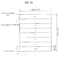
- FIG. 13 is a diagram for one example of reference center frequency configuration for each of N partial bands according to a 1st embodiment of the present invention. Particularly, in case of FIG. 13 , a full system band having a bandwidth of K Hz is divided into N partial bands.
- a reference center frequency for each partial band can be represented as Table 4 in the following. [Table 4] Partial band Reference center frequency Time-axis reference signal density (maximum L per TTI ) 0 C L 0 1 C + K / N L 1 2 C + 2K / N L 0 ⁇ ⁇ ⁇ N-1 C + (N-1)K / N L N-1
- RS density ⁇ TTI T C ⁇ ⁇ the numder of required RSs
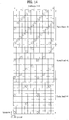
- FIG. 14 is a diagram for one example of assigning a time-axis reference signal pattern of different density for each partial band according to a 1st embodiment of the present invention. Particularly, in FIG. 14 , assume that the total number of partial bands is 3 and that reference signal densities required for the partial bands are set to values different from each other by 1 time, 2 times and 3 times, respectively. Yet, assume that a frequency-axis reference signal density is set equal for each partial band.
- a following method is proposed. First of all, the same reference signal density is maintained for a full bandwidth. Secondly, a low frequency band over a center frequency, i.e., a bottom band, is preferentially assigned to a user equipment that is moving faster. Thirdly, a high frequency band over a center frequency, i.e., a top band, is preferentially assigned to a user equipment that is moving relatively slow.
- a base station preferentially assigns a bottom band, of which reference center frequency is low, in case of resource allocation to a user equipment.
- This is a scheduling method for securing channel estimation performance on a moving speed of a user equipment as far as possible.
- a top band is preferentially assigned. This is attributed to the following reason. First of all, even if a reference center frequency gets higher, when a moving sped of a user equipment is low, Doppler's frequency gets lower but a coherent time gets longer. Hence, a reference signal density required within the same TTI is decreased.
- a 3rd embodiment of the present invention proposes a method of flexibly configuring a reference signal pattern for each band per TTI/subframe/system frame.
- a predetermined pattern or periodicity is configured and managed.
- a flexible frame in a manner of transmitting subframe configuration/reconfiguration information to a user equipment by dynamic signaling or upper layer signaling such as RRC signaling.
- a base station can maximize a gain of a system by adjusting a rate of a subframe, in which a specific reference signal is transmitted, in accordance with a communication situation within a corresponding service coverage.
- a subframe/TTI structure having a different reference signal pattern is shared by a user equipment and a base station.
- the base station can transmit a specific subframe triggered location or a subframe index information to the user equipment. This is described in detail with reference to the accompanying drawing.
- FIG. 15 is a diagram for one example of applying a reference signal pattern differing for each subframe according to a 3rd embodiment of the present invention. Particularly, in FIG. 15 , assume that a frame having reference signal densities of two types exist. And, assume that this intra-subframe reference signal configuration is already known to a base station and a user equipment.
- a base station determines a situation of a user equipment within a service coverage and then changes a frame configuration.
- a reference signal pattern of subframes #1 to #4 and a reference signal pattern of subframes #6 to #9 are assigned.
- subframes #0 and #5 configured as a pattern of a low reference signal density are assigned.
- a frame can be configured to have a specific reference signal density only.
- a base statin in configuring a subframe, can transmit a corresponding information to a user equipment. For instance, if a single system frame consists of 10 subframes, as shown in FIG. 15 , a subframe information configured with a single reference signal density can be transmitted to the user equipment in a manner of being configured as a bitmap such as '1000010000'. On the contrary, in case of generating a system information centering on a subframe information configured with multiple reference signal densities, the system information can be transmitted to the user equipment in a manner of being configured as a bitmap such as '0111101111'.
- the base statin can decide a ratio of a low-density reference signal pattern applied band to a high-density reference signal pattern applied band by determining moving situations of user equipments.
- the user equipment should be provided with a channel estimator appropriate for each subframe in accordance with the subframe configuration information delivered from the base station or can activate and deactivate the channel estimator. For instance, the user equipment should perform channel estimation using a single channel estimator in the single reference signal density subframe. And, the user equipment should activate channel estimators corresponding to the number of different RS density partial bands in multi-RS density subframe.
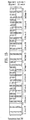
- FIG. 16 is a block diagram for one example of a communication device according to one embodiment of the present invention.
- a communication device 1600 includes a processor 1610, a memory 1620, an RF module 1630, a display module 1640 and a user interface module 1650.
- the communication device 1600 is illustrated for clarity and convenience of the description and some modules can be omitted. Moreover, the communication device 1600 is able to further include at least one necessary module. And, some modules of the communication device 1600 can be further divided into sub-modules.
- the processor 1610 is configured to perform operations according to the embodiment of the present invention exemplarily described with reference to the accompanying drawings. In particular, the detailed operations of the processor 1610 can refer to the contents described with reference to FIGs. 1 to 15 .
- the memory 1620 is connected to the processor 1610 and stores operating systems, applications, program codes, data and the like.
- the RF module 1630 is connected to the processor 1610 and performs a function of converting a baseband signal to a radio signal or converting a radio signal to a baseband signal. For this, the RF module 1630 performs analog conversion, amplification, filtering and frequency uplink transform or inverse processes thereof.
- the display module 1640 is connected to the processor 1610 and displays various kinds of informations.
- the display module 1640 can include such a well-known element as LCD (Liquid Crystal Display), LED (Light Emitting Diode), OLED (Organic Light Emitting Diode) and the like, by which the present invention is non-limited.
- the user interface module 1650 is connected to the processor 1610 and can include a combination of well-known interfaces including a keypad, a touchscreen and the like.
- Embodiments of the present invention can be implemented using various means. For instance, embodiments of the present invention can be implemented using hardware, firmware, software and/or any combinations thereof. In case of the implementation by hardware, a method according to one embodiment of the present invention can be implemented by at least one selected from the group consisting of ASICs (application specific integrated circuits), DSPs (digital signal processors), DSPDs (digital signal processing devices), PLDs (programmable logic devices), FPGAs (field programmable gate arrays), processor, controller, microcontroller, microprocessor and the like.
- ASICs application specific integrated circuits
- DSPs digital signal processors
- DSPDs digital signal processing devices
- PLDs programmable logic devices
- FPGAs field programmable gate arrays
- processor controller, microcontroller, microprocessor and the like.
- a method according to each embodiment of the present invention can be implemented by modules, procedures, and/or functions for performing the above-explained functions or operations.
- Software code is stored in a memory unit and is then drivable by a processor.
- the memory unit is provided within or outside the processor to exchange data with the processor through the various means known in public.
Description
- The present invention relates to a wireless communication system, and more particularly, to a method of transmitting a reference signal from a base station to a user equipment in a wireless communication system and apparatus therefor.
- 3GPP LTE (3rd generation partnership projecting long term evolution) communication system is schematically described for one example of a wireless communication system to which the present invention is applicable.
-
FIG. 1 is a schematic diagram of E-UMTS network structure as an example of a wireless communication system. E-UMTS (evolved universal mobile telecommunications system) is the system evolved from a conventional UMTS (universal mobile telecommunications system) and its basic standardization is progressing by 3GPP. Generally, E-UMTS can be called LTE (long term evolution) system. For the details of the technical specifications of UMTS and E-UMTS,Release 7 andRelease 8 of '3rd Generation Partnership Project: Technical Specification Group Radio Access Network' can be referred to. - Referring to
FIG. 1 , E-UMTS consists of a user equipment (UE) 120, base stations (eNode B: eNB) 110a and 110b and an access gateway (AG) provided to an end terminal of a network (E-UTRAN) to be connected to an external network. The base station is able to simultaneously transmit multi-data stream for a broadcast service, a multicast service and/or a unicast service. - At least one or more cells exist in one base station. The cell is set to one of bandwidths including 1.25 MHz, 2.5 MHz, 5 MHz, 10 MHz, 15 MHz, 20 MHz and the like and then provides an uplink or downlink transmission service to a plurality of user equipments. Different cells can be set to provide different bandwidths, respectively. A base station controls data transmissions and receptions for a plurality of user equipments. A base station sends downlink scheduling information on downlink (DL) data to inform a corresponding user equipment of time/frequency region for transmitting data to the corresponding user equipment, coding, data size, HARQ (hybrid automatic repeat and request) relevant information and the like. And, the base station sends uplink scheduling information on uplink (UL) data to a corresponding user equipment to inform the corresponding user equipment of time/frequency region available for the corresponding user equipment, coding, data size, HARQ relevant information and the like. An interface for a user traffic transmission or a control traffic transmission is usable between base stations. A core network (CN) can consist of an AG, a network node for user registration of a user equipment and the like. The AG manages mobility of the user equipment by a unit of TA (tracking area) including a plurality of cells.
- The wireless communication technology has been developed up to LTE based on WCDMA but the demands and expectations of users and service providers are continuously rising. Since other radio access technologies keep being developed, new technological evolution is requested to become competitive in the future. For this, reduction of cost per bit, service availability increase, flexible frequency band use, simple-structure and open interface, reasonable power consumption of user equipment and the like are required.
-
US 2007/104174 discloses a set of different pilot structures that are designed for use in different environments and/or different user behaviors that are expected to occur in a cell. The radio conditions for a user are estimated. Each user is then assigned an area (108 A-E) in resource space for its communication, which has a suitable pilot configuration. In one embodiment, the entire resource space is provided with different pilot structures in different parts (110 A-D). In advance and allocation of resources to the users are then performed in order to match estimated radio conditions to the provided pilot structure. In another embodiment, allocation is performed first, and then the actual pilot structure is adapted within the allocated resource space area to suit the environmental conditions. - The invention is set out in the appended claims. The references to embodiments in the description falling outside the scope of the appended claims are to be understood as mere examples which are useful for understanding the invention. Based on the above-mentioned discussion, a method of transmitting a reference signal from a base station to a user equipment in a wireless communication system and apparatus therefor shall be proposed in the following description.
- Technical tasks obtainable from the present invention are non-limited by the above-mentioned technical task. And, other unmentioned technical tasks can be clearly understood from the following description by those having ordinary skill in the technical field to which the present invention pertains.
- To achieve these and other advantages and in accordance with the purpose of the present invention, as embodied and broadly described, a method of transmitting a reference signal, which is transmitted by a base station to a user equipment in a wireless communication system, according to one embodiment of the present invention includes the steps of dividing a system band into at least one or more partial bands, configuring a time-axis high density reference signal on a high frequency partial band with reference to a center frequency of the system band, configuring a time-axis low density reference signal
on a low frequency partial band with reference to the center frequency, and transmitting the configured reference signals to the user equipment. - Preferably, the method may further include the steps of configuring different time-axis density reference signals for subframes included in a system frame and transmitting subframe configuration information including information on the different time-axis density reference signals to the user equipment. In this case, the subframe configuration information may be defined as a bitmap by unit of the system frame including a predetermined number of subframes.
- To further achieve these and other advantages and in accordance with the purpose of the present invention, a base in a wireless communication system according to another embodiment of the present invention includes a processor for dividing a system band into at least one or more partial bands, for configuring a time-axis high density reference signal on a high frequency partial band with reference to a center frequency of the system band, and for configuring a time-axis low density reference signal on a low frequency partial band with reference to the center frequency and a transmitting module for transmitting the configured reference signals to a user equipment.
- Preferably, the processor may configure different time-axis density reference signals for subframes included in a system frame and the processor may control the transmitting module to transmit subframe configuration information including information on the different time-axis density reference signals to the user equipment.
- More preferably, if a high-speed user equipment and a low-speed user equipment coexist in a coverage, the processor may configure the time-axis high density reference signal and the time-axis low density reference signal on the high frequency partial band and the low frequency partial band, respectively. Moreover, if the low-speed user equipment exists in the coverage, the processor may configure the time-axis low density reference signal across the system band.
- More preferably, the system frame may include a 1st subframe type having both the time-axis high density reference signal and the time-axis low density reference signal and a 2nd subframe type having the time-axis low density reference signal only. Furthermore, a frequency-axis density of the time-axis high density reference signal may be equal to that of the time-axis low density reference signal.
- The above-mentioned general description of the present invention and the following details of the present invention are exemplary and may be provided for the additional description of the invention disclosed in claims.
- Accordingly, the present invention may provide the following effects and/or features.
- First of all, according to an embodiment of the present invention, a base station in a wireless communication system can perform a reference signal transmission appropriate for channel properties in a manner of configuring a reference signal density or pattern differing on each frequency band.
- Effects obtainable from the present invention may be non-limited by the above mentioned effect. And, other unmentioned effects can be clearly understood from the following description by those having ordinary skill in the technical field to which the present invention pertains.
- It is to be understood that both the foregoing general description and the following detailed description of the present invention are exemplary and explanatory and are intended to provide further explanation of the invention as claimed.
- The accompanying drawings, which are included to provide a further understanding of the invention and are incorporated in and constitute a part of this specification, illustrate embodiments of the invention and together with the description serve to explain the principles of the invention.
-
FIG. 1 is a schematic diagram of E-UMTS network structure as an example of a mobile communication system. -
FIG. 2 is a diagram of structures of control and user planes of a radio interface protocol between a user equipment and E-UTRAN based on 3GPP radio access network specification. -
FIG. 3 is a diagram for explaining physical channels used for 3GPP system and a general method of transmitting a signal using the same. -
FIG. 4 is a diagram for a configuration of a general multi-antenna (MIMO) communication system; -
FIG. 5 is a diagram for one example of a structure of a downlink (DL) subframe used by LTE system; -
FIG. 6 is a diagram for one example of a structure of an uplink (UL) subframe used by LTE system; -
FIG. 7 and FIG. 8 are diagrams for structures of a downlink reference signal in LTE system supportive of a downlink transmission using 4 antennas. -
FIG. 9 is a diagram for one example of downlink DM-RS assignment currently defined in 3GPP standard document. -
FIG. 10 is a diagram for one example of CSI-RS configuration # 0 in case of a normal CP in the downlink CSI-RS configuration currently defined in 3GPP standard document. -
FIG. 11 is a diagram for one example of small-cell concept expected to be introduced into LTE system. -
FIG. 12 is a diagram for one example of broadband system bandwidth assignment on a high frequency. -
FIG. 13 is a diagram for one example of reference center frequency configuration for each of N partial bands according to a 1st embodiment of the present invention. -
FIG. 14 is a diagram for one example of assigning a time-axis reference signal pattern of different density for each partial band according to a 1st embodiment of the present invention. -
FIG. 15 is a diagram for one example of applying a reference signal pattern differing for each subframe according to a 3rd embodiment of the present invention. -
FIG. 16 is a block diagram for one example of a communication device according to one embodiment of the present invention. - Reference will now be made in detail to the preferred embodiments of the present invention, examples of which are illustrated in the accompanying drawings. The embodiments described in the following description include the examples showing that the technical features of the present invention are applied to 3GPP system.
- Although an embodiment of the present invention is exemplarily described in the present specification using the LTE system and the LTE-A system, the embodiment of the present invention is also applicable to any kinds of communication systems corresponding to the above definitions. Although an embodiment of the present invention is exemplarily described with reference to FDD scheme in the present specification, the embodiment of the present invention is easily modifiable and applicable to H-FDD or TDD scheme.
-
FIG. 2 is a diagram of structures of control and user planes of a radio interface protocol between a user equipment and E-UTRAN based on 3GPP radio access network specification. First of all, a control plane means a passage for transmitting control messages used by a user equipment and a network to manage a call. A user plane means a passage for transmitting such data generated from an application layer as voice data, internet packet data and the like. - A physical layer, i.e., a first layer, provides information transfer service to an upper layer using a physical channel. The physical layer is connected to a medium access control layer located above via a transport channel. Data are transferred between the medium access control layer and the physical layer via the transport channel. Data are transferred between a physical layer of a transmitting side and a physical layer of a receiving side via a physical channel. The physical channel uses time and frequency as radio resources. In particular, a physical layer is modulated in downlink by OFDMA (orthogonal frequency division multiple access) scheme and is modulated in uplink by SC-FDMA (single carrier frequency division multiple access) scheme.
- A medium access control (hereinafter abbreviated MAC) layer of a second layer provides a service to a radio link control (hereinafter abbreviated RLC) layer of an upper layer via a logical channel. The RLC layer of the second layer supports reliable data transfer. A function of the RLC layer can be implemented using a function block within the MAC. A packet data convergence protocol (hereinafter abbreviated PDCP) layer of the second layer performs a header compression function for reducing unnecessary control information to transmit such an IP packet as IPv4 and IPv6 in a radio interface having a narrow bandwidth.
- A radio resource control (hereinafter abbreviated RRC) layer located on a lowest level of a third layer is defined in a control plane only. The RRC layer is responsible for controlling logical channel, transport channel and physical channels in association with configuration, reconfiguration and release of radio bearers (RBs). In this case, the RB means a service provided by the second layer for a data transfer between a user equipment and a network. For this, the RRC layer of the user equipment exchanges RRC messages with the RRC layer of the network. In case that an RRC connection is established between an RRC layer of a user equipment and an RRC layer of a network, the user equipment is in a connected mode. Otherwise, the user equipment is in an idle mode. NAS (non-access stratum) layer above an RRC layer performs a function of session management, a function of mobility management and the like.
- One cell, which constructs a base station (eNB), is set to one of bandwidths including 1.25 MHz, 2.5 MHz, 5 MHz, 10 MHz, 15 MHz, 20 MHz and the like and then provides an uplink or downlink transmission service to a plurality of user equipments. Different cells can be set to provide different bandwidths, respectively.
- A downlink transport channel for transporting data to a user equipment from a network includes a broadcast channel (BCH) for transporting system information, a paging channel (PCH) for transmitting a paging message, a downlink shared channel (SCH) for transmitting a user traffic or a control message or the like. A traffic or control message of a downlink multicast or broadcast service can be transmitted via a downlink SCH or a separate downlink multicast channel (MCH). Meanwhile, an uplink transport channel for transmitting data from a user equipment to a network includes a random access channel for transmitting an initial control message, an uplink shared channel (SCH) for transmitting a user traffic or a control message or the like. A logical channel located above a transport channel to be mapped by a transport channel includes BCCH (Broadcast Control Channel), PCCH (Paging Control Channel), CCCH (Common Control Channel), MCCH (Multicast Control Channel), MTCH (Multicast Traffic Channel) or the like.
-
FIG. 3 is a diagram for explaining physical channels used by 3GPP system and a general signal transmitting method using the same. - If a power of a user equipment is turned on or the user equipment enters a new cell, the user equipment performs an initial cell search for matching synchronization with a base station and the like [S301]. For this, the user equipment receives a primary synchronization channel (P-SCH) and a secondary synchronization channel (S-SCH) from the base station, matches synchronization with the base station and then obtains information such as a cell ID and the like. Subsequently, the user equipment receives a physical broadcast channel from the base station and is then able to obtain intra-cell broadcast information. Meanwhile, the user equipment receives a downlink reference signal (DL RS) in the initial cell searching step and is then able to check a downlink channel status.
- Having completed the initial cell search, the user equipment receives a physical downlink control channel (PDCCH) and a physical downlink shared control channel (PDSCH) according to information carried on the physical downlink control channel (PDCCH) and is then able to obtain system information in further detail [S302].
- Meanwhile, if the user equipment initially accesses the base station or fails to have a radio resource for signal transmission, the user equipment is able to perform a random access procedure (RACH) on the base station [S303 to S306]. For this, the user equipment transmits a specific sequence as a preamble via a physical random access channel (PRACH) [S303, S305] and is then able to receive a response message via PDCCH and a corresponding PDSCH in response to the preamble [S304, S306]. In case of contention based RACH, it is able to perform a contention resolution procedure in addition.
- Having performed the above mentioned procedures, the user equipment is able to perform PDCCH/PDSCH reception [S307] and PUSCH/PUCCH (physical uplink shared channel/physical uplink control channel) transmission [S308] as a general uplink/downlink signal transmission procedure. In particular, the user equipment receives a downlink control information (DCI) via PDCCH. In this case, the DCI includes such control information as resource allocation information on a user equipment and can differ in format in accordance with the purpose of its use.
- Meanwhile, control information transmitted/received in uplink/downlink to/from the base station by the user equipment includes ACK/NACK signal, CQI (channel quality indicator), PMI (precoding matrix index), RI (rank indicator) and the like. In case of the 3GPP LTE system, the user equipment is able to transmit the above mentioned control information such as CQI, PMI, RI and the like via PUSCH and/or PUCCH.
- In the following description, MIMO system is explained. First of all, MIMO (multi-input multi-output) is a method that uses a plurality of transmitting antennas and a plurality of receiving antennas. And, this method may be able to improve efficiency in transceiving data. In particular, a transmitting or receiving stage of a wireless communication system uses a plurality of antennas to increase capacity or enhance performance. In the following description, the MIMO may be called 'multiple antennas (multi-antenna)'.
- The MIMO technology does not depend on a single antenna path to receive one whole message. Instead, the MIMO technique completes data by putting fragments received via several antennas together. If the MIMO technique is adopted, a data transmission rate within a cell area having a specific size may be improved or a system coverage may be increased by securing a specific data transmission rate. Moreover, this technique may be widely applicable to a mobile communication terminal, a relay and the like. According to the MIMO technique, it may be able to overcome the transmission size limit of the related art mobile communication which used to use a single data.
-
FIG. 4 is a diagram for a configuration of a multi-antenna (MIMO) communication system explained in the description of the present invention. NT transmitting antennas are provided to a transmitting stage, while NR receiving antennas are provided to a receiving stage. In case that each of the transmitting and receiving stages uses a plurality of antennas, theoretical channel transmission capacity is increased more than that of a case that either the transmitting stage or the receiving stage uses a plurality of antennas. The increase of the channel transmission capacity is in proportion to the number of antennas. Hence, a transmission rate is enhanced and frequency efficiency can be raised. Assuming that a maximum transmission rate in case of using a single antenna is set to R0, the transmission rate in case of using multiple antennas may be theoretically raised by a result from multiplying the maximum transmission rate R0 by a rate increasing rate Ri, as shown inFormula 1. In this case, Ri is a smaller one of NT and NR.
- For instance, in an MIMO communication system, which uses 4 transmitting antennas and 4 receiving antennas, it may be able to obtain a
transmission rate 4 times higher than that of a single antenna system. After this theoretical capacity increase of the MIMO system has been proved in the middle of 90's, many ongoing efforts are made to various techniques to substantially improve a data transmission rate. And, these techniques are already adopted in part as standards for the 3G mobile communications and various wireless communications such as a next generation wireless LAN and the like. - The trends for the MIMO relevant studies are explained as follows. First of all, many ongoing efforts are made in various aspects to develop and research information theory study relevant to MIMO communication capacity calculations and the like in various channel configurations and multiple access environments, radio channel measurement and model derivation study for MIMO systems, spatiotemporal signal processing technique study for transmission reliability enhancement and transmission rate improvement and the like.
- In order to explain a communicating method in an MIMO system in detail, mathematical modeling can be represented as follows. Referring to
FIG. 4 , assume that NT transmitting antennas and NR receiving antennas exist. First of all, regarding a transmission signal, if there are NT transmitting antennas, NT maximum transmittable informations exist. Hence, the transmission information may be represented by the vector shown inFormula 2.
- Meanwhile, transmission powers can be set different from each other for transmission informations s 1 , s 2,···, sN
T , respectively. If the transmission powers are set to P 1, P 2,···, PNT , respectively, the transmission power adjusted transmission information can be represented asFormula 3.
- And, Ŝ may be represented as
Formula 4 using a diagonal matrix P of the transmission power.
- Let us consider a case of configuring NT transmitted signals x 1, x 2,···,xN
T , which are actually transmitted, by applying a weight matrix W to a transmission power adjusted information vector Ŝ. In this case, the weight matrix plays a role in properly distributing each transmission information to each antenna according to a transmission channel status and the like. The transmitted signals are set to x 1, x 2,···, xNT may be represented asFormula 5 using a vector X. In this case, W ij means a weight between an ith transmitting antenna and a jth information. And, the W may be called a weight matrix or a precoding matrix.
- Generally, a physical meaning of a rank of a channel matrix may indicate a maximum number for carrying different informations on a granted channel. Since a rank of a channel matrix is defined as a minimum number of the numbers of independent rows or columns, a rank of a channel is not greater than the number of rows or columns. For example by formula, a rank of a channel H (i.e., rank (H)) is limited by
Formula 6.
- Meanwhile, each different information sent by MIMO technology may be defined as 'transport stream' or 'stream' simply. This 'stream' may be called a layer. If so, the number of transport streams is unable to be greater than a channel rank, which is the maximum number for sending different informations. Hence, the channel matrix H may be represented as
Formula 7.
In this case, '# of streams' may indicate the number of streams. Meanwhile, it should be noted that one stream is transmittable via at least one antenna. - Various methods for making at least one stream correspond to several antennas may exist. These methods may be described in accordance with a type of MIMO technique as follows. First of all, if one stream is transmitted via several antennas, it may be regarded as spatial diversity. If several streams are transmitted via several antennas, it may be regarded as spatial multiplexing. Of course, such an intermediate type between spatial diversity and spatial multiplexing as a hybrid type of spatial diversity and spatial multiplexing may be possible.
-
FIG. 5 is a diagram for one example of a control channel included in a control region of one subframe in a downlink (DL) radio subframe. - Referring to
FIG. 5 , a subframe may include 14 OFDM symbols. First 1 to 3 OFDM symbols may be used as a control region and the rest of 13 to 11 OFDM symbols may be used as a data region, in accordance with subframe configurations. In the drawing, R1 to R4 indicate reference signals (RS) forantennas 0 to 3, respectively. The RS may be fixed to a predetermined pattern in a subframe irrespective of the control region or the data region. The control region may be assigned to a resource, to which the RS is not assigned, in the control region. And, a traffic channel may be assigned to a resource, to which the RS is not assigned, in the data region. Control channels assigned to the control region may include PCFICH (Physical Control Format Indicator CHannel), PHICH (Physical Hybrid-ARQ Indicator CHannel), PDCCH (Physical Downlink Control CHannel) and the like. - The PCFICH is a physical control format indicator channel and informs a user equipment of the number of OFDM symbols used for PDCCH in each subframe. The PCFICH is situated at a first OFDM symbol and is set prior to the PHICH and the PDCCH. The PCFICH is constructed with four resource element groups (REGs). Each of the REGs is distributed within the control region based on a cell ID. One REG is constructed with four REs. In this case, the RE indicates a minimum physical resource defined as '1 subcarrier x 1 OFDM symbol'. A value of the PCFICH indicates a value of '1 ∼ 3' or '2 ∼ 4' and is modulated by QPSK (quadrature phase shift keying).
- The PHICH is a physical HARQ (hybrid-automatic repeat and request) indicator channel and is used in carrying HARQ ACK/NACK for uplink transmission. In particular, the PHICH indicates a channel for carrying DL ACK/NACK information for UL HARQ. The PHICH is constructed with 1 REG and is cell-specifically scrambled. The ACK/NACK is indicated by 1 bit and then modulated by BPSK (binary phase shift keying). The modulated ACK/NACK is spread by 'SF (spreading factor) = 2 or 4'. A plurality of PHICHs mapped to the same resource configure a PHICH group. The number of the PHICHs multiplexed into the PHICH group is determined depending on the number of spreading codes. And, the PHICH (group) is repeated three times to obtain a diversity gain in frequency domain and/or time domain.
- The PDCCH is a physical downlink control channel and is assigned to first n OFDM symbols of a subframe. In this case, 'n' is an integer equal to or greater than 1 and is indicated by the PCFICH. The PDCCH informs each user equipment or UE group of resource allocation information on transport channels PCH (paging channel) and DL-SCH (downlink-shared channel), uplink scheduling grant, HARQ information and the like. The PCH (paging channel) and the DL-SCH (downlink-shared channel) are carried on the PDSCH. Therefore, a base station or a user equipment normally transmits or receives data via the PDSCH except specific control information or specific service data.
- Information indicating that data of the PDSCH is transmitted to a prescribed user equipment (or a plurality of user equipments), information indicating how the user equipments receive and decode PDSCH data, and the like are transmitted by being included in the PDCCH. For instance, assume that a specific PDCCH is CRC masked with RNTI (radio network temporary identity) 'A' and that information on data transmitted using a radio resource 'B' (e.g., frequency position) and transmission format information 'C' (e.g., transport block size, modulation scheme, coding information, etc.) is transmitted via a specific subframe. If so, at least one user equipment located in a corresponding cell monitors PDCCH using RNTI information of its own. If there is at least one user equipment having the RNTI 'A', the user equipments receive the PDCCH and then receive PDSCH indicated by 'B' and 'C' through the information of the received PDCCH.
-
FIG. 6 is a diagram for one example of a structure of an uplink (UL) subframe used by LTE system. - Referring to
FIG. 6 , a UL subframe may be divided into a region for assigning PUCCH (physical uplink control channel) configured to carry control information and a region for assigning PUSCH (physical uplink shared channel) configured to carry user data. A middle part of a subframe is assigned to the PUSCH and both side parts of a data region in frequency domain are assigned to the PUSCH. The control information carried on the PUCCH may include ACK/NACK used for HARQ, CQI (channel quality indicator) indicating a DL Channel state, an RI (rank indicator) for MIMO, an SR (scheduling request) that is a UL resource allocation request, and the like. The PUCCH for a single user equipment uses a single resource block occupying a different frequency in each slow within a subframe. In particular, a pair of resource blocks assigned to the PUCCH experience frequency hopping on a slot boundary. Specifically,FIG. 6 shows one example that PUCCH (m = 0), PUCCH (m = 1), PUCCH (m = 2), and PUCCH (m = 3) are assigned to the subframe. - In the following description, reference signals are explained in detail.
- First of all, a reference signal already known to both a transmitting side and a receiving side is generally transmitted for channel measurement to the receiving side from the transmitting side together with data. This reference signal is provided for the channel measurement and also indicates a modulation scheme to play a role in enabling a demodulation process. Reference signals can be categorized into a dedicated reference signal (DRS) for a specific user equipment (UE) and a dedicated reference signal for a base station, i.e., a UE-specific reference signal and a common reference signal (common RS or CRS (cell-specific RS) that is a cell-specific reference signal for all user equipments within a cell. Moreover, the cell-specific reference signal includes a reference signal for measuring and reporting CQI/PMI/RI to a base station from a user equipment. And, such a reference signal is called CSI-RS (channel state information-RS).
-
FIG. 7 and FIG. 8 are diagrams for structures of a downlink reference signal in LTE system supportive of a downlink transmission using 4 antennas. Particularly,FIG. 7 shows a case of a normal cyclic prefix andFIG. 8 shows a case of an extended cyclic prefix. - Referring to
FIG. 7 and FIG. 8 ,numerals 0 to 3 entered in a grid correspond toports 0 to 3 and mean common reference signals (CRS) that are cell-specific reference signals transmitted for channel measurement and data demodulation, respectively. The cell-specific reference signals, CRS, can be transmitted to a user equipment across a control information region and a data information region. - 'D' entered in the grid means a downlink DM-RS (demodulation-RS) that is a UE-specific RS. The DM-RS supports a single antenna port transmission on PDSCH. A user equipment receives a signaling of a presence or non-presence of DMRS, which is a UE-specific RS, through an upper layer.
FIG. 7 and FIG. 8 show examples of DM-RS corresponding to anantenna port 5. In 3GPP standard document 36.211, DM-RSs forantenna ports 7 to 14, i.e., total 8 antenna ports, are defined as well. -
FIG. 9 is a diagram for one example of downlink DM-RS assignment currently defined in 3GPP standard document. - Referring to
FIG. 9 , DM-RSs corresponding toantenna ports # 7, #8, #11 and #13 in DM-RS Group 1 are mapped using a sequence per antenna port. Likewise, DM-RSs corresponding toantenna ports # 9, #10, #12 and #14 in DM-RS Group 2 are mapped using a sequence per antenna port. - Aside from CRS, the above-mentioned CSI-RS is proposed for the purpose of channel measurement of PDSCH. Unlike CRS, CSI-RSs can be defined into maximum 32 kinds of different CSI-RS configurations in order to reduce inter-cell interference (ICI) in a multi-cell environment.
- CSI-RS configurations differ from each other depending on the number of antenna ports. Between neighboring cells, CSI-RS is configured to be transmitted in a manner of being defined to have a CSI-RS configuration as different as possible. Unlike CRS, CSI-RS supports maximum 8 antenna ports. In 3GPP standard document, total 8 antenna ports including antenna ports 15 to 22 are assigned as antenna ports for CSI-RS. In the following,
- Table 1 and Table 2 show CSI-RS configurations defined in 3GPP standard document. Particularly, Table 1 show a case of a normal CP and Table 2 show a case of an extended CP.


- In Table 1 and Table 2, (k', l') indicates an RE index, k' indicates a subcarrier index, and l' indicates an OFDM symbol index.
FIG. 10 is a diagram for one example of CSI-RS configuration # 0 in case of a normal CP in the downlink CSI-RS configuration currently defined in 3GPP standard document. - Moreover, CSI-RS subframe configuration can be defined, which is configured with a periodicity T CSI-RS represented by subframe unit and a subframe offset ΔCSI-RS. Table 3 in the following shows CSI-RS subframe configuration defined in 3GPP standard document.
[Table 3] CSI-RS-SubframeConfig I CSI-RS CSI-RS periodicity T CSI-RS (subframes) CSI-RS subframe offset ΔCSI-RS (subframes) 0 - 4 5 I CSI-RS 5 - 14 10 I CSI-RS - 5 15 - 34 20 I CSI-RS - 15 35 - 74 40 I CSI-RS - 35 75 - 154 80 I CSI-RS - 75 - LTE system is planning to adopt a local area. In particular, in order to reinforce a service support for each user, it is expected to introduce new cell deployment in the concept of a local area access.
-
FIG. 11 is a diagram for one example of small-cell concept expected to be introduced into LTE system. - Referring to
FIG. 11 , a wider system bandwidth is configured on a higher center frequency band, instead of a frequency band operating in the previous LTE system, and may be then operated possibly. Moreover, a basic cell coverage is supported on an existing cellular band based on such a control signal as system information and a wider frequency band is used in a small cell of high frequency, whereby data transmission can be performed by maximizing transmission efficiency. Hence, the concept of a local area access targets low-to-medium mobility user equipments located in a narrower area and may include small cells. And, a distance between a user equipment and a base station in each of the small cells corresponds to 100m-unit smaller than the km-unit of an existing cell. - In the above-mentioned cells, a distance between a user equipment and a base station decreases and a high frequency band is used, whereby the following channel characteristics can be expected.
- First of all, in aspect of delayed spreading, as a distance between a base station and a user equipment decreases, a delay of a signal may decrease. Secondly, in aspect of subcarrier spacing, in case that an OFDM based frame identical to that of LTE system is applied, since an assigned frequency band is relatively wide, the subcarrier spacing may be set to a value extremely greater than 15 kHz. Finally, in aspect of Doppler's frequency, since a high frequency band is used, Doppler's frequency higher than a low frequency band of the same user equipment speed appears. Hence, a coherent time may decrease extremely. In this case, the coherent time means a time interval in which a channel has static or uniform characteristics temporally. A coherent bandwidth means a bandwidth in which a channel has static or uniform characteristics temporally.
- Generally, in order to design a reference signal, it is necessary to regulate a target center frequency (fc) and a maximum moving speed of a user equipment. Since a bandwidth size, which is one of major factors, has a relatively small ratio over a center frequency, a representative center frequency per system band can be approximated to an existing center frequency. Actually, although a maximum bandwidth is 20 MHz in LTE system, in order to support a
center frequency 2 GHz and a maximum moving sped 580 km/h of a user equipment for a full system band, a reference signal (RS), particularly, a cell-specific reference signal (CRS) is designed. Actually, assuming that a center frequency and a UE's maximum moving speed are 2 GHz and 500 km/h, respectively, maximum Doppler's frequency becomes 1,074 HZ, i.e., about 1,000 Hz.
- Generally, a coherent time can get about 50% from a maximum Doppler's frequency. Hence, in LTE system, the relation shown in
Formula 10 can be established.
InFormula 10, Tc indicates a coherent time and fd indicates Doppler's frequency. Such a relation may mean that maximum two RSs are necessary within the coherence time. In particular, in LTE system, CRS is designed to maintain density of 4 reference signals on a time axis in 1ms subframe in order to support UE's moving speed corresponding to Doppler's frequency of about 1,000 Hz. - Yet, for a frequency band having a central frequency amounting to several tens of GHz, a transmission using a bandwidth amounting to several hundreds of MHz or several GHz is considered instead of an existing bandwidth amounting to several tens of MHz. In this situation, a system bandwidth can be calculated as a value that cannot be ignored in consideration of a center frequency. Namely, for instance, if a center frequency and a bandwidth are set to 2 GHz and 20 MHz, respectively, a bandwidth over a center frequency is 1%. Yet, if a center frequency and a bandwidth are set to 10 GHz and 1 GHz, respectively, a bandwidth over a center frequency increases to 10%.
- Hence, a user equipment may have a center frequency differing in accordance with a position of a serviced bandwidth. For instance, if a center frequency and a UE's moving speed are set to 10 GHz and 200 km/h, respectively, a maximum Doppler's frequency can be calculated as
Formula 11.
- This is described in detail with reference to the accompanying drawing as follows.
FIG. 12 is a diagram for one example of broadband system bandwidth assignment on a high frequency. Particularly, inFIG. 12 , assume that a system bandwidth and a UE's moving speed are set to 1 GHz and 200 km/h, respectively, under the same center frequency. - Referring to
FIG. 12 , if Doppler's frequencies at top, middle and bottom within a bandwidth are found asFormulas 12 to 14 in the following. In this case, a center frequency correction value means a bandwidth-added/deducted center frequency of a user equipment at each location.


- Referring to
Formulas 12 to 14, it can be observed that a Doppler's frequency difference between top and bottom within a bandwidth increases up to maximum 200 Hz. Coherent times at top, middle and bottom are calculated as Formulas 15 to 17, respectively. Likewise, the meaning of the coherent time means that at least two reference signals are required within each coherent time.


- Hence, for accurate channel estimation on a high frequency band, more reference signals are necessary within the same time if a center frequency gets higher. If a center frequency gets lower, the same channel estimation can be achieved using less reference signals. Yet, regarding a reference signal required density difference in accordance with a center frequency negligible in an existing system design, probability of a generation of the density difference within a single system bandwidth increases if a center frequency gets lower and a transmission bandwidth gets wider. Moreover, if a moving speed of a user equipment gets higher, the difference further increases.
- For efficient bandwidth management of a system having a wider transmission bandwidth over a center frequency, the present invention proposes a time-axis reference signal pattern design that is variable per band.
- To solve the above-described problems, a 1st embodiment of the present invention proposes a method of configuring a reference signal pattern differing per partial band on a full frequency band. In particular, reference signals are not configured to have the same density on a full system band but reference signals are configured to differ in density per band.
- First of all, after a full transmission band has been divided into N partial bands, each of the partial band is configured to have a different time-axis reference signal density. In particular, centering on a center frequency for a full frequency band, a reference signal pattern of low density is configured on a bottom partial band, while a reference signal pattern of high density is configured on a top partial band.
- The 1st embodiment of the present invention is suitable for a communication environment of which transmission band is a broadband with a center frequency of high frequency. In particular, this means the environment in which a size a transmission band over a center frequency increases up to a significant value greater than a reference value in accordance with a location at which a resource is allocated to a user equipment. In this case, since a coherent time attributed to a center frequency and a moving speed of a user equipment varies for each partial band, the coherent time is derived with reference to different center frequency values and a reference signal pattern is configured. This is to support the UE's moving speed that is the same system requirement for the whole band.
-
FIG. 13 is a diagram for one example of reference center frequency configuration for each of N partial bands according to a 1st embodiment of the present invention. Particularly, in case ofFIG. 13 , a full system band having a bandwidth of K Hz is divided into N partial bands. In this case, a reference center frequency for each partial band can be represented as Table 4 in the following.[Table 4] Partial band Reference center frequency Time-axis reference signal density (maximum L per TTI ) 0 C L 0 1 C+K/ N L 1 2 C+2K/N L0 ⋮ ⋮ ⋮ N-1 C+(N-1)K/N LN-1 - In Table 4, it is able to calculate a coherent time for each partial band using a modified center frequency. And, it is able to configure reference signals using the calculated coherent times in a manner that each of the partial bands has a different reference signal density. The reference signal density (RS density) required for each partial band can be defined as Formula 18 in the following.

- Since a reference center frequency increases in proportion to an increase of a partial band index in
FIG. 13 and Table 4, a coherent time gets shorter but a time-axis reference signal density required for accurate channel estimation increases within the same TTI (transmission time interval). -
FIG. 14 is a diagram for one example of assigning a time-axis reference signal pattern of different density for each partial band according to a 1st embodiment of the present invention. Particularly, inFIG. 14 , assume that the total number of partial bands is 3 and that reference signal densities required for the partial bands are set to values different from each other by 1 time, 2 times and 3 times, respectively. Yet, assume that a frequency-axis reference signal density is set equal for each partial band. - Of course, in aspect of a user equipment, it is necessary to be equipped with channel estimators corresponding to the number of partial bands differing from each other in a reference signal pattern.
- According to a 2nd embodiment, a following method is proposed. First of all, the same reference signal density is maintained for a full bandwidth. Secondly, a low frequency band over a center frequency, i.e., a bottom band, is preferentially assigned to a user equipment that is moving faster. Thirdly, a high frequency band over a center frequency, i.e., a top band, is preferentially assigned to a user equipment that is moving relatively slow.
- In particular, in case that the same reference signal density is maintained for a full band, a base station preferentially assigns a bottom band, of which reference center frequency is low, in case of resource allocation to a user equipment. This is a scheduling method for securing channel estimation performance on a moving speed of a user equipment as far as possible. On the other hand, if a moving speed of a user equipment is low or a user equipment is in a static situation, a top band is preferentially assigned. This is attributed to the following reason. First of all, even if a reference center frequency gets higher, when a moving sped of a user equipment is low, Doppler's frequency gets lower but a coherent time gets longer. Hence, a reference signal density required within the same TTI is decreased.
- Meanwhile, a 3rd embodiment of the present invention proposes a method of flexibly configuring a reference signal pattern for each band per TTI/subframe/system frame.
- Particularly, in managing and operating a subframe having a reference signal pattern differing on each partial band in density like the 1st embodiment, a predetermined pattern or periodicity is configured and managed. In more particular, instead of applying the same subframe configuration to every TTI or subframe all the time, it is possible to apply a flexible frame in a manner of transmitting subframe configuration/reconfiguration information to a user equipment by dynamic signaling or upper layer signaling such as RRC signaling. A base station can maximize a gain of a system by adjusting a rate of a subframe, in which a specific reference signal is transmitted, in accordance with a communication situation within a corresponding service coverage.
- In particular, a subframe/TTI structure having a different reference signal pattern is shared by a user equipment and a base station. The base station can transmit a specific subframe triggered location or a subframe index information to the user equipment. This is described in detail with reference to the accompanying drawing.
-
FIG. 15 is a diagram for one example of applying a reference signal pattern differing for each subframe according to a 3rd embodiment of the present invention. Particularly, inFIG. 15 , assume that a frame having reference signal densities of two types exist. And, assume that this intra-subframe reference signal configuration is already known to a base station and a user equipment. - Referring to
FIG. 15 , it can be observed that a base station determines a situation of a user equipment within a service coverage and then changes a frame configuration. In particular, if a high-speed user equipment and a low-speed user equipment coexist in the service coverage, a reference signal pattern ofsubframes # 1 to #4 and a reference signal pattern ofsubframes # 6 to #9, as shown inFIG. 15 , are assigned. Yet, if the number of the low-speed user equipments absolutely dominates over that of the high-speed user equipments in the service coverage,subframes # 0 and #5 configured as a pattern of a low reference signal density are assigned. - In doing so, the rate of partial bands differing from each other in reference signal density of each frame can be extremely adjusted. And, a frame can be configured to have a specific reference signal density only.
- In addition, in configuring a subframe, a base statin can transmit a corresponding information to a user equipment. For instance, if a single system frame consists of 10 subframes, as shown in
FIG. 15 , a subframe information configured with a single reference signal density can be transmitted to the user equipment in a manner of being configured as a bitmap such as '1000010000'. On the contrary, in case of generating a system information centering on a subframe information configured with multiple reference signal densities, the system information can be transmitted to the user equipment in a manner of being configured as a bitmap such as '0111101111'. - In configuring multi-RS density subframe/TTI, it is able to define a corresponding rate in advance. Yet, the rate can be flexibly set through RRC signaling. In doing so, the base statin can decide a ratio of a low-density reference signal pattern applied band to a high-density reference signal pattern applied band by determining moving situations of user equipments.
- Finally, the user equipment should be provided with a channel estimator appropriate for each subframe in accordance with the subframe configuration information delivered from the base station or can activate and deactivate the channel estimator. For instance, the user equipment should perform channel estimation using a single channel estimator in the single reference signal density subframe. And, the user equipment should activate channel estimators corresponding to the number of different RS density partial bands in multi-RS density subframe.
- In the above description, the method of configuring and applying a reference signal appropriate for a communication environment that uses a broadband on a high frequency band is explained. And, it is a matter of course that the same method is applicable to a small cell as well as to an existing macro cell.
-
FIG. 16 is a block diagram for one example of a communication device according to one embodiment of the present invention. - Referring to
FIG. 16 , acommunication device 1600 includes aprocessor 1610, amemory 1620, anRF module 1630, adisplay module 1640 and auser interface module 1650. - The
communication device 1600 is illustrated for clarity and convenience of the description and some modules can be omitted. Moreover, thecommunication device 1600 is able to further include at least one necessary module. And, some modules of thecommunication device 1600 can be further divided into sub-modules. Theprocessor 1610 is configured to perform operations according to the embodiment of the present invention exemplarily described with reference to the accompanying drawings. In particular, the detailed operations of theprocessor 1610 can refer to the contents described with reference toFIGs. 1 to 15 . - The
memory 1620 is connected to theprocessor 1610 and stores operating systems, applications, program codes, data and the like. TheRF module 1630 is connected to theprocessor 1610 and performs a function of converting a baseband signal to a radio signal or converting a radio signal to a baseband signal. For this, theRF module 1630 performs analog conversion, amplification, filtering and frequency uplink transform or inverse processes thereof. Thedisplay module 1640 is connected to theprocessor 1610 and displays various kinds of informations. Thedisplay module 1640 can include such a well-known element as LCD (Liquid Crystal Display), LED (Light Emitting Diode), OLED (Organic Light Emitting Diode) and the like, by which the present invention is non-limited. Theuser interface module 1650 is connected to theprocessor 1610 and can include a combination of well-known interfaces including a keypad, a touchscreen and the like. - The above-described embodiments correspond to combination of elements and features of the present invention in prescribed forms. And, it is able to consider that the respective elements or features are selective unless they are explicitly mentioned. Each of the elements or features can be implemented in a form failing to be combined with other elements or features. Moreover, it is able to implement an embodiment of the present invention by combining elements and/or features together in part. A sequence of operations explained for each embodiment of the present invention can be modified. Some configurations or features of one embodiment can be included in another embodiment or can be substituted for corresponding configurations or features of another embodiment. It is apparent that an embodiment can be configured by combining claims, which are not explicitly cited in-between, together without departing from the spirit and scope of 'what is claimed is' or that those claims can be included as new claims by revision after filing an application.
- Embodiments of the present invention can be implemented using various means. For instance, embodiments of the present invention can be implemented using hardware, firmware, software and/or any combinations thereof. In case of the implementation by hardware, a method according to one embodiment of the present invention can be implemented by at least one selected from the group consisting of ASICs (application specific integrated circuits), DSPs (digital signal processors), DSPDs (digital signal processing devices), PLDs (programmable logic devices), FPGAs (field programmable gate arrays), processor, controller, microcontroller, microprocessor and the like.
- In case of the implementation by firmware or software, a method according to each embodiment of the present invention can be implemented by modules, procedures, and/or functions for performing the above-explained functions or operations. Software code is stored in a memory unit and is then drivable by a processor. The memory unit is provided within or outside the processor to exchange data with the processor through the various means known in public.
- Although a method of transmitting a reference signal from a base station to a user equipment in a wireless communication system and apparatus therefor are described mainly with reference to examples applied to 3GPP LTE system, as mentioned in the foregoing description, the present invention is applicable to various kinds of wireless communication systems as well as the 3GPP LTE system.
Claims (6)
- A method of transmitting reference signals to a user equipment by a base station in a wireless communication system, the method comprising:configuring a first reference signal having a first time-axis density and a second reference signal having a second time-axis density,wherein the first reference signal is configured on a first partial band and the second reference signal is configured on a second partial band;transmitting subframe configuration information to the user equipment; andtransmitting the configured reference signals to the user equipment based on the subframe configuration information,wherein a frequency of the first partial band is higher than a frequency of the second partial band;wherein the first time-axis density is higher than the second time-axis density, andwherein the subframe configuration information indicates whether each subframe is a 1st type subframe having both the first reference signal and the second reference signal or a 2nd type subframe having the second reference signal only.
- The method of claim 1, wherein the subframe configuration information is defined as a bitmap by unit of a system frame including a predetermined number of subframes.
- The method of claim 1, wherein a frequency-axis density of the first reference signal is equal to the frequency-axis density of the second reference signal.
- A base station in a wireless communication system, the base station comprising:a processor for configuring a first reference signal having a first time-axis density and a second reference signal having a second time-axis density, wherein the first reference signal is configured on a first partial band and the second reference signal is configured on a second partial band; anda transmitting module for transmitting subframe configuration information to a user equipment and transmitting the configured reference signals to the user equipment based on the subframe configuration information,wherein a frequency of the first partial band is higher than a frequency of the second partial band, andwherein the first time-axis density is higher than the second time-axis density,wherein the subframe configuration information indicates whether each subframe is a 1st type subframe having both the first reference signal and the second reference signal or a 2nd type subframe having the second reference signal only.
- The base station of claim 4, wherein the subframe configuration information is defined as a bitmap by unit of the system frame including a predetermined number of subframes.
- The base station of claim 4, wherein a frequency-axis density of the first reference signal is equal to the frequency-axis density of the second reference signal.
Applications Claiming Priority (2)
| Application Number | Priority Date | Filing Date | Title |
|---|---|---|---|
| US201361763904P | 2013-02-12 | 2013-02-12 | |
| PCT/KR2013/007451 WO2014126311A1 (en) | 2013-02-12 | 2013-08-20 | A method of transmitting a reference signal from a base station to a user equipment in a wireless communication system and apparatus therefor |
Publications (3)
| Publication Number | Publication Date |
|---|---|
| EP2957048A1 EP2957048A1 (en) | 2015-12-23 |
| EP2957048A4 EP2957048A4 (en) | 2016-09-07 |
| EP2957048B1 true EP2957048B1 (en) | 2019-10-23 |
Family
ID=51354295
Family Applications (1)
| Application Number | Title | Priority Date | Filing Date |
|---|---|---|---|
| EP13874997.3A Active EP2957048B1 (en) | 2013-02-12 | 2013-08-20 | A method of transmitting a reference signal from a base station to a user equipment in a wireless communication system and apparatus therefor |
Country Status (5)
| Country | Link |
|---|---|
| US (1) | US9794037B2 (en) |
| EP (1) | EP2957048B1 (en) |
| JP (1) | JP6058820B2 (en) |
| KR (1) | KR20150117677A (en) |
| WO (1) | WO2014126311A1 (en) |
Families Citing this family (14)
| Publication number | Priority date | Publication date | Assignee | Title |
|---|---|---|---|---|
| US9602322B2 (en) * | 2014-08-01 | 2017-03-21 | Qualcomm Incorporated | Transmission and reception of discovery signals over a radio frequency spectrum band |
| US10348523B2 (en) * | 2015-06-11 | 2019-07-09 | Lg Electronics Inc. | Reference signal configuration method for V2V communication in wireless communication system, and apparatus therefor |
| CN107318086B (en) * | 2016-04-26 | 2020-03-20 | 华为技术有限公司 | Method and device for allocating time-frequency resources |
| US10771299B2 (en) * | 2016-08-10 | 2020-09-08 | Qualcomm Incorporated | Reference signal configurations for doppler support in new radio design |
| EP3282624B1 (en) * | 2016-08-10 | 2019-05-15 | Alcatel Lucent | Device and user equipment to process a channel state information reference signal |
| WO2018062842A1 (en) | 2016-09-27 | 2018-04-05 | Samsung Electronics Co., Ltd. | Method and apparatus for receiving downlink reference signal in wireless communication system |
| CN107872305B (en) | 2016-09-27 | 2021-11-05 | 北京三星通信技术研究有限公司 | Method and device for receiving downlink reference signal |
| CN114567932A (en) * | 2016-09-30 | 2022-05-31 | 华为技术有限公司 | Data transmission method, related device and system |
| CN109804572B (en) | 2016-10-11 | 2022-08-30 | 瑞典爱立信有限公司 | Method for adapting the density of a demodulation reference signal |
| CN110431897B (en) * | 2017-03-23 | 2023-03-21 | Oppo广东移动通信有限公司 | Wireless communication method, apparatus and computer readable medium |
| CN108632005B (en) | 2017-03-24 | 2023-12-15 | 华为技术有限公司 | Reference signal transmission method, device and system |
| WO2018171792A1 (en) * | 2017-03-24 | 2018-09-27 | 华为技术有限公司 | Method, apparatus and system for reference signal transmission |
| US11128419B2 (en) | 2017-04-03 | 2021-09-21 | Lg Electronics Inc. | Reference signal reception method and user equipment, and reference signal transmission method and base station |
| WO2018209596A1 (en) * | 2017-05-17 | 2018-11-22 | Qualcomm Incorporated | Csi-rs configuration for partial band retuning |
Family Cites Families (10)
| Publication number | Priority date | Publication date | Assignee | Title |
|---|---|---|---|---|
| KR100507519B1 (en) * | 2002-12-13 | 2005-08-17 | 한국전자통신연구원 | Method and Apparatus for Signal Constitution for Downlink of OFDMA Based Cellular Systems |
| EP1542488A1 (en) * | 2003-12-12 | 2005-06-15 | Telefonaktiebolaget LM Ericsson (publ) | Method and apparatus for allocating a pilot signal adapted to the channel characteristics |
| WO2007042898A1 (en) * | 2005-10-07 | 2007-04-19 | Nokia Corporation | Apparatus, method and computer program product providing common pilot channel for soft frequency reuse |
| EP2615766A3 (en) * | 2006-04-28 | 2014-01-22 | Nec Corporation | Pilot signal transmitting method, radio communication system, and apparatus and program used for the same |
| JP5045127B2 (en) * | 2007-01-31 | 2012-10-10 | 富士通モバイルコミュニケーションズ株式会社 | Wireless communication system |
| JP2008288736A (en) | 2007-05-15 | 2008-11-27 | Mitsubishi Electric Corp | Transmission apparatus, receiving apparatus, and communication system |
| US8537790B2 (en) * | 2008-03-10 | 2013-09-17 | Motorola Mobility Llc | Hierarchical pilot structure in wireless communication systems |
| JPWO2010016240A1 (en) | 2008-08-05 | 2012-01-19 | パナソニック株式会社 | Wireless communication apparatus and power density setting method |
| WO2010085054A2 (en) * | 2009-01-21 | 2010-07-29 | Lg Electronics Inc. | Method of transmitting and receiving data in a wireless system |
| KR101996075B1 (en) * | 2011-01-07 | 2019-07-03 | 인터디지탈 패튼 홀딩스, 인크 | Communicating channel state information (csi) of multiple transmission points |
-
2013
- 2013-08-20 EP EP13874997.3A patent/EP2957048B1/en active Active
- 2013-08-20 KR KR1020157023063A patent/KR20150117677A/en not_active Application Discontinuation
- 2013-08-20 WO PCT/KR2013/007451 patent/WO2014126311A1/en active Application Filing
- 2013-08-20 US US14/767,075 patent/US9794037B2/en active Active
- 2013-08-20 JP JP2015556865A patent/JP6058820B2/en not_active Expired - Fee Related
Non-Patent Citations (1)
| Title |
|---|
| None * |
Also Published As
| Publication number | Publication date |
|---|---|
| JP2016507195A (en) | 2016-03-07 |
| WO2014126311A1 (en) | 2014-08-21 |
| EP2957048A4 (en) | 2016-09-07 |
| KR20150117677A (en) | 2015-10-20 |
| JP6058820B2 (en) | 2017-01-11 |
| US9794037B2 (en) | 2017-10-17 |
| US20150381331A1 (en) | 2015-12-31 |
| EP2957048A1 (en) | 2015-12-23 |
Similar Documents
| Publication | Publication Date | Title |
|---|---|---|
| EP2957048B1 (en) | A method of transmitting a reference signal from a base station to a user equipment in a wireless communication system and apparatus therefor | |
| EP3116150B1 (en) | Method for receiving discovery reference signal by terminal in wireless communication system and device therefor | |
| EP3242416B1 (en) | Method for receiving downlink data channels in multicell-based wireless communication systems and apparatus for same | |
| US9344299B2 (en) | CSI-RS based channel estimating method in a wireless communication system and device for same | |
| EP2929636B1 (en) | Changing of pattern of reference signals according to coherence time variation in wireless communication system | |
| US9713134B2 (en) | Method and device for allocating resource for downlink control channel in wireless communication system, and apparatus therefor | |
| EP2929708B1 (en) | Method for changing pattern of reference signals according to movement speed of user equipment in wireless communication system, and an apparatus therefor | |
| US10873946B2 (en) | Method for transmitting signal by using multi-beam in wireless communication system, and apparatus therefor | |
| US9755768B2 (en) | Method for measuring channel and interference in wireless communication system | |
| JP6838151B2 (en) | DM-RS transmission method for broadcast data in next-generation communication systems and equipment for that purpose | |
| JP2014510433A (en) | Sounding reference signal transmission method and apparatus therefor in multi-antenna wireless communication system | |
| US9544112B2 (en) | Method by which terminal transmits and receives signal in multi cell-based wireless communication system, and device for same | |
| US9854571B2 (en) | Method and apparatus for acquiring diversity gain according to distributed resource allocation for downlink control channel in wireless communication system | |
| JP6082481B2 (en) | Method and apparatus for transmitting a control channel from a base station to a terminal in a wireless communication system | |
| US20140036851A1 (en) | Method for sending and receiving signals for alleviating inter-cell interference in a wireless communication system and a device therefor | |
| US10812151B2 (en) | Method for transmitting and receiving signal between base station and vehicle terminal in distributed antenna communication system and apparatus therefor | |
| EP2929639B1 (en) | Method for changing pattern of reference signals according to rank variation in wireless communication system, and an apparatus therefor | |
| US9161346B2 (en) | Method for transmitting control channel in multicell cooperative wireless communication system and device therefor | |
| KR102205894B1 (en) | Priority-based interference control method in wireless communication system and apparatus therefor | |
| KR102243636B1 (en) | Method for reducing interference between uplink signal and downlink signal, and apparatus therefor |
Legal Events
| Date | Code | Title | Description |
|---|---|---|---|
| PUAI | Public reference made under article 153(3) epc to a published international application that has entered the european phase |
Free format text: ORIGINAL CODE: 0009012 |
|
| 17P | Request for examination filed |
Effective date: 20150814 |
|
| AK | Designated contracting states |
Kind code of ref document: A1 Designated state(s): AL AT BE BG CH CY CZ DE DK EE ES FI FR GB GR HR HU IE IS IT LI LT LU LV MC MK MT NL NO PL PT RO RS SE SI SK SM TR |
|
| AX | Request for extension of the european patent |
Extension state: BA ME |
|
| DAX | Request for extension of the european patent (deleted) | ||
| A4 | Supplementary search report drawn up and despatched |
Effective date: 20160808 |
|
| RIC1 | Information provided on ipc code assigned before grant |
Ipc: H04W 88/08 20090101ALN20160802BHEP Ipc: H04L 5/00 20060101AFI20160802BHEP |
|
| REG | Reference to a national code |
Ref country code: DE Ref legal event code: R079 Ref document number: 602013062129 Country of ref document: DE Free format text: PREVIOUS MAIN CLASS: H04B0007260000 Ipc: H04L0005000000 |
|
| GRAP | Despatch of communication of intention to grant a patent |
Free format text: ORIGINAL CODE: EPIDOSNIGR1 |
|
| STAA | Information on the status of an ep patent application or granted ep patent |
Free format text: STATUS: GRANT OF PATENT IS INTENDED |
|
| RIC1 | Information provided on ipc code assigned before grant |
Ipc: H04L 5/00 20060101AFI20190516BHEP Ipc: H04W 88/08 20090101ALN20190516BHEP |
|
| INTG | Intention to grant announced |
Effective date: 20190604 |
|
| GRAS | Grant fee paid |
Free format text: ORIGINAL CODE: EPIDOSNIGR3 |
|
| GRAA | (expected) grant |
Free format text: ORIGINAL CODE: 0009210 |
|
| STAA | Information on the status of an ep patent application or granted ep patent |
Free format text: STATUS: THE PATENT HAS BEEN GRANTED |
|
| AK | Designated contracting states |
Kind code of ref document: B1 Designated state(s): AL AT BE BG CH CY CZ DE DK EE ES FI FR GB GR HR HU IE IS IT LI LT LU LV MC MK MT NL NO PL PT RO RS SE SI SK SM TR |
|
| REG | Reference to a national code |
Ref country code: GB Ref legal event code: FG4D |
|
| REG | Reference to a national code |
Ref country code: CH Ref legal event code: EP |
|
| REG | Reference to a national code |
Ref country code: IE Ref legal event code: FG4D |
|
| REG | Reference to a national code |
Ref country code: DE Ref legal event code: R096 Ref document number: 602013062129 Country of ref document: DE |
|
| REG | Reference to a national code |
Ref country code: AT Ref legal event code: REF Ref document number: 1194889 Country of ref document: AT Kind code of ref document: T Effective date: 20191115 |
|
| REG | Reference to a national code |
Ref country code: NL Ref legal event code: MP Effective date: 20191023 |
|
| REG | Reference to a national code |
Ref country code: LT Ref legal event code: MG4D |
|
| PG25 | Lapsed in a contracting state [announced via postgrant information from national office to epo] |
Ref country code: PT Free format text: LAPSE BECAUSE OF FAILURE TO SUBMIT A TRANSLATION OF THE DESCRIPTION OR TO PAY THE FEE WITHIN THE PRESCRIBED TIME-LIMIT Effective date: 20200224 Ref country code: BG Free format text: LAPSE BECAUSE OF FAILURE TO SUBMIT A TRANSLATION OF THE DESCRIPTION OR TO PAY THE FEE WITHIN THE PRESCRIBED TIME-LIMIT Effective date: 20200123 Ref country code: FI Free format text: LAPSE BECAUSE OF FAILURE TO SUBMIT A TRANSLATION OF THE DESCRIPTION OR TO PAY THE FEE WITHIN THE PRESCRIBED TIME-LIMIT Effective date: 20191023 Ref country code: PL Free format text: LAPSE BECAUSE OF FAILURE TO SUBMIT A TRANSLATION OF THE DESCRIPTION OR TO PAY THE FEE WITHIN THE PRESCRIBED TIME-LIMIT Effective date: 20191023 Ref country code: LT Free format text: LAPSE BECAUSE OF FAILURE TO SUBMIT A TRANSLATION OF THE DESCRIPTION OR TO PAY THE FEE WITHIN THE PRESCRIBED TIME-LIMIT Effective date: 20191023 Ref country code: NO Free format text: LAPSE BECAUSE OF FAILURE TO SUBMIT A TRANSLATION OF THE DESCRIPTION OR TO PAY THE FEE WITHIN THE PRESCRIBED TIME-LIMIT Effective date: 20200123 Ref country code: GR Free format text: LAPSE BECAUSE OF FAILURE TO SUBMIT A TRANSLATION OF THE DESCRIPTION OR TO PAY THE FEE WITHIN THE PRESCRIBED TIME-LIMIT Effective date: 20200124 Ref country code: ES Free format text: LAPSE BECAUSE OF FAILURE TO SUBMIT A TRANSLATION OF THE DESCRIPTION OR TO PAY THE FEE WITHIN THE PRESCRIBED TIME-LIMIT Effective date: 20191023 Ref country code: NL Free format text: LAPSE BECAUSE OF FAILURE TO SUBMIT A TRANSLATION OF THE DESCRIPTION OR TO PAY THE FEE WITHIN THE PRESCRIBED TIME-LIMIT Effective date: 20191023 Ref country code: LV Free format text: LAPSE BECAUSE OF FAILURE TO SUBMIT A TRANSLATION OF THE DESCRIPTION OR TO PAY THE FEE WITHIN THE PRESCRIBED TIME-LIMIT Effective date: 20191023 Ref country code: SE Free format text: LAPSE BECAUSE OF FAILURE TO SUBMIT A TRANSLATION OF THE DESCRIPTION OR TO PAY THE FEE WITHIN THE PRESCRIBED TIME-LIMIT Effective date: 20191023 |
|
| PG25 | Lapsed in a contracting state [announced via postgrant information from national office to epo] |
Ref country code: RS Free format text: LAPSE BECAUSE OF FAILURE TO SUBMIT A TRANSLATION OF THE DESCRIPTION OR TO PAY THE FEE WITHIN THE PRESCRIBED TIME-LIMIT Effective date: 20191023 Ref country code: IS Free format text: LAPSE BECAUSE OF FAILURE TO SUBMIT A TRANSLATION OF THE DESCRIPTION OR TO PAY THE FEE WITHIN THE PRESCRIBED TIME-LIMIT Effective date: 20200224 Ref country code: HR Free format text: LAPSE BECAUSE OF FAILURE TO SUBMIT A TRANSLATION OF THE DESCRIPTION OR TO PAY THE FEE WITHIN THE PRESCRIBED TIME-LIMIT Effective date: 20191023 |
|
| PG25 | Lapsed in a contracting state [announced via postgrant information from national office to epo] |
Ref country code: AL Free format text: LAPSE BECAUSE OF FAILURE TO SUBMIT A TRANSLATION OF THE DESCRIPTION OR TO PAY THE FEE WITHIN THE PRESCRIBED TIME-LIMIT Effective date: 20191023 |
|
| REG | Reference to a national code |
Ref country code: DE Ref legal event code: R097 Ref document number: 602013062129 Country of ref document: DE |
|
| PG2D | Information on lapse in contracting state deleted |
Ref country code: IS |
|
| PG25 | Lapsed in a contracting state [announced via postgrant information from national office to epo] |
Ref country code: EE Free format text: LAPSE BECAUSE OF FAILURE TO SUBMIT A TRANSLATION OF THE DESCRIPTION OR TO PAY THE FEE WITHIN THE PRESCRIBED TIME-LIMIT Effective date: 20191023 Ref country code: DK Free format text: LAPSE BECAUSE OF FAILURE TO SUBMIT A TRANSLATION OF THE DESCRIPTION OR TO PAY THE FEE WITHIN THE PRESCRIBED TIME-LIMIT Effective date: 20191023 Ref country code: RO Free format text: LAPSE BECAUSE OF FAILURE TO SUBMIT A TRANSLATION OF THE DESCRIPTION OR TO PAY THE FEE WITHIN THE PRESCRIBED TIME-LIMIT Effective date: 20191023 Ref country code: CZ Free format text: LAPSE BECAUSE OF FAILURE TO SUBMIT A TRANSLATION OF THE DESCRIPTION OR TO PAY THE FEE WITHIN THE PRESCRIBED TIME-LIMIT Effective date: 20191023 Ref country code: IS Free format text: LAPSE BECAUSE OF FAILURE TO SUBMIT A TRANSLATION OF THE DESCRIPTION OR TO PAY THE FEE WITHIN THE PRESCRIBED TIME-LIMIT Effective date: 20200223 |
|
| REG | Reference to a national code |
Ref country code: AT Ref legal event code: MK05 Ref document number: 1194889 Country of ref document: AT Kind code of ref document: T Effective date: 20191023 |
|
| PLBE | No opposition filed within time limit |
Free format text: ORIGINAL CODE: 0009261 |
|
| STAA | Information on the status of an ep patent application or granted ep patent |
Free format text: STATUS: NO OPPOSITION FILED WITHIN TIME LIMIT |
|
| PG25 | Lapsed in a contracting state [announced via postgrant information from national office to epo] |
Ref country code: SK Free format text: LAPSE BECAUSE OF FAILURE TO SUBMIT A TRANSLATION OF THE DESCRIPTION OR TO PAY THE FEE WITHIN THE PRESCRIBED TIME-LIMIT Effective date: 20191023 Ref country code: SM Free format text: LAPSE BECAUSE OF FAILURE TO SUBMIT A TRANSLATION OF THE DESCRIPTION OR TO PAY THE FEE WITHIN THE PRESCRIBED TIME-LIMIT Effective date: 20191023 Ref country code: IT Free format text: LAPSE BECAUSE OF FAILURE TO SUBMIT A TRANSLATION OF THE DESCRIPTION OR TO PAY THE FEE WITHIN THE PRESCRIBED TIME-LIMIT Effective date: 20191023 |
|
| 26N | No opposition filed |
Effective date: 20200724 |
|
| PG25 | Lapsed in a contracting state [announced via postgrant information from national office to epo] |
Ref country code: SI Free format text: LAPSE BECAUSE OF FAILURE TO SUBMIT A TRANSLATION OF THE DESCRIPTION OR TO PAY THE FEE WITHIN THE PRESCRIBED TIME-LIMIT Effective date: 20191023 Ref country code: AT Free format text: LAPSE BECAUSE OF FAILURE TO SUBMIT A TRANSLATION OF THE DESCRIPTION OR TO PAY THE FEE WITHIN THE PRESCRIBED TIME-LIMIT Effective date: 20191023 |
|
| PG25 | Lapsed in a contracting state [announced via postgrant information from national office to epo] |
Ref country code: MC Free format text: LAPSE BECAUSE OF FAILURE TO SUBMIT A TRANSLATION OF THE DESCRIPTION OR TO PAY THE FEE WITHIN THE PRESCRIBED TIME-LIMIT Effective date: 20191023 |
|
| REG | Reference to a national code |
Ref country code: CH Ref legal event code: PL |
|
| GBPC | Gb: european patent ceased through non-payment of renewal fee |
Effective date: 20200820 |
|
| PG25 | Lapsed in a contracting state [announced via postgrant information from national office to epo] |
Ref country code: LI Free format text: LAPSE BECAUSE OF NON-PAYMENT OF DUE FEES Effective date: 20200831 Ref country code: CH Free format text: LAPSE BECAUSE OF NON-PAYMENT OF DUE FEES Effective date: 20200831 Ref country code: LU Free format text: LAPSE BECAUSE OF NON-PAYMENT OF DUE FEES Effective date: 20200820 |
|
| REG | Reference to a national code |
Ref country code: BE Ref legal event code: MM Effective date: 20200831 |
|
| PG25 | Lapsed in a contracting state [announced via postgrant information from national office to epo] |
Ref country code: FR Free format text: LAPSE BECAUSE OF NON-PAYMENT OF DUE FEES Effective date: 20200831 |
|
| PG25 | Lapsed in a contracting state [announced via postgrant information from national office to epo] |
Ref country code: IE Free format text: LAPSE BECAUSE OF NON-PAYMENT OF DUE FEES Effective date: 20200820 Ref country code: GB Free format text: LAPSE BECAUSE OF NON-PAYMENT OF DUE FEES Effective date: 20200820 Ref country code: BE Free format text: LAPSE BECAUSE OF NON-PAYMENT OF DUE FEES Effective date: 20200831 |
|
| PG25 | Lapsed in a contracting state [announced via postgrant information from national office to epo] |
Ref country code: TR Free format text: LAPSE BECAUSE OF FAILURE TO SUBMIT A TRANSLATION OF THE DESCRIPTION OR TO PAY THE FEE WITHIN THE PRESCRIBED TIME-LIMIT Effective date: 20191023 Ref country code: MT Free format text: LAPSE BECAUSE OF FAILURE TO SUBMIT A TRANSLATION OF THE DESCRIPTION OR TO PAY THE FEE WITHIN THE PRESCRIBED TIME-LIMIT Effective date: 20191023 Ref country code: CY Free format text: LAPSE BECAUSE OF FAILURE TO SUBMIT A TRANSLATION OF THE DESCRIPTION OR TO PAY THE FEE WITHIN THE PRESCRIBED TIME-LIMIT Effective date: 20191023 |
|
| PG25 | Lapsed in a contracting state [announced via postgrant information from national office to epo] |
Ref country code: MK Free format text: LAPSE BECAUSE OF FAILURE TO SUBMIT A TRANSLATION OF THE DESCRIPTION OR TO PAY THE FEE WITHIN THE PRESCRIBED TIME-LIMIT Effective date: 20191023 |
|
| PGFP | Annual fee paid to national office [announced via postgrant information from national office to epo] |
Ref country code: DE Payment date: 20220615 Year of fee payment: 10 |
|
| REG | Reference to a national code |
Ref country code: DE Ref legal event code: R119 Ref document number: 602013062129 Country of ref document: DE |