EP2956766B1 - Probe-holder for amperometric sensor - Google Patents
Probe-holder for amperometric sensor Download PDFInfo
- Publication number
- EP2956766B1 EP2956766B1 EP14714352.3A EP14714352A EP2956766B1 EP 2956766 B1 EP2956766 B1 EP 2956766B1 EP 14714352 A EP14714352 A EP 14714352A EP 2956766 B1 EP2956766 B1 EP 2956766B1
- Authority
- EP
- European Patent Office
- Prior art keywords
- probe
- holder
- duct
- holding
- amperometric sensor
- Prior art date
- Legal status (The legal status is an assumption and is not a legal conclusion. Google has not performed a legal analysis and makes no representation as to the accuracy of the status listed.)
- Active
Links
Images



Classifications
-
- G—PHYSICS
- G01—MEASURING; TESTING
- G01N—INVESTIGATING OR ANALYSING MATERIALS BY DETERMINING THEIR CHEMICAL OR PHYSICAL PROPERTIES
- G01N33/00—Investigating or analysing materials by specific methods not covered by groups G01N1/00 - G01N31/00
- G01N33/18—Water
-
- G—PHYSICS
- G01—MEASURING; TESTING
- G01N—INVESTIGATING OR ANALYSING MATERIALS BY DETERMINING THEIR CHEMICAL OR PHYSICAL PROPERTIES
- G01N27/00—Investigating or analysing materials by the use of electric, electrochemical, or magnetic means
- G01N27/26—Investigating or analysing materials by the use of electric, electrochemical, or magnetic means by investigating electrochemical variables; by using electrolysis or electrophoresis
- G01N27/28—Electrolytic cell components
Definitions
- the present invention relates to a probe-holder configured to house an amperometric sensor for sensing the concentration of at least one specific substance possibly dissolved (e.g., chlorine) in a fluid, optionally water, that flows in the probe-holder, possibly besides other sensing probes for sensing physico-chemical parameters of the fluid, that allows to carry out precise, efficient and reliable measurements of the concentration of said at least one substance.
- an amperometric sensor for sensing the concentration of at least one specific substance possibly dissolved (e.g., chlorine) in a fluid, optionally water, that flows in the probe-holder, possibly besides other sensing probes for sensing physico-chemical parameters of the fluid, that allows to carry out precise, efficient and reliable measurements of the concentration of said at least one substance.
- probe-holding module for amperometric sensor that constitutes an embodiment of the probe-holder for amperometric sensor according to the invention, wherein the probe-holding module for amperometric sensor is assembled in a modular probe-holder applied to water treatment.
- the probe-holder for amperometric sensor according to the invention may be a different probe-holder, for instance a monolithic (i.e. non-modular) probe-holder configured to house only an amperometric sensor or configured to house, besides the amperometric sensor, other sensing probes for sensing physico-chemical parameters of the fluid, such as flow meters, and that the probe-holder for amperometric sensor according to the invention may be applied in any other technological context in which the physico-chemical parameters of any fluid, even different from water, must be monitored and/or controlled, still remaining within the scope of protection of the present invention as defined in the attached claims.
- sensing probes are used, which are arranged along a sensing path in which water that is to undergo sensing at least partially flows.
- sensing probes are housed in a dedicated compartment of a monolithic probe-holder, usually of plastic material, provided with an inlet and an outlet, that is part of such sensing path.
- the inventors have developed a modular probe-holder composed of two or more probe-holding modules, with reference to which the invention will be illustrated in the following.
- amperometric sensors are commonly used, as illustrated for instance by the prior art documents US4129479 , WO 02/101400 A1 and WO 2012/085641 A1 .
- a probe-holder having a first and a second side walls, configured to house an amperometric sensor in a side hollow seat, the probe-holder comprising an inlet and an outlet and a longitudinal duct connected downstream of the side hollow seat, the probe-holder being configured to receive a flow of a fluid from the inlet to the outlet, the probe-holder further comprising a space downstream of the inlet and upstream of the side hollow seat, the probe-holder being characterised in that the space is connected to the side hollow seat through a plurality of two or more inner tubular ducts inclined by an inclination angle ⁇ with respect to a transversal plane crossing the first and second side walls of the probe-holder.
- the inclination angle ⁇ of each inner tubular duct with respect to said transversal plane may range from 20° to 30°.
- each inner tubular duct with respect to said transversal plane may be equal to 25°.
- the side hollow seat may be connected to the longitudinal duct through one or more planar ducts oriented parallel to a longitudinal axis of the longitudinal duct.
- said one or more planar ducts may be oriented orthogonally to said transversal plane crossing the right and left walls of the probe-holder.
- the space may comprise a, optionally threaded, mouth communicating externally.
- the mouth may be connected to the inlet through a transversal duct.
- the probe-holder may further comprise a transversal duct connected between the inlet of the probe-holder and the longitudinal duct, whereby the transversal duct is configured to operate as by-pass for air mixed with said incoming fluid entering the probe-holder.
- the longitudinal duct may be vertical
- the side hollow seat may be arranged inferiorly to the longitudinal duct and the outlet of the probe-holder may be superiorly arranged on a side wall selected between the first and the second side walls, whereby the longitudinal duct is configured to receive said flow of a fluid from the bottom upwards.
- the probe-holder configured to house an amperometric sensor according to the invention allows the solute to be agitated in an efficient way in correspondence to the amperometric sensor for obtaining a reliable and precise concentration measurement.
- some embodiments of the probe-holder for amperometric sensor according to the invention are provided with a by-pass for air mixed with the fluid entering the probe-holder, that allows to make a degassing of the entering fluid that is particularly important for avoiding malfunctions of the amperometric sensor; in particular, the amount of air mixed with the fluid is larger when the fluid starts to flow in the probe-holder.
- a first embodiment of the probe-holder for amperometric sensor is a probe-holding module for amperometric sensor applied to a modular probe-holder that may be composed of two or more probe-holding modules coupled to each other the type of which is selected from a group comprising five types of different probe-holding modules, each one made in one piece of plexiglass that can be inscribed in a substantially parallelepiped-shaped polyhedron, and capable to be coupled to each other.
- the probe-holding module for amperometric sensor is a fifth type of probe-holding module 500, shown in Figures 1e and 2b , that is configured to house a horizontal amperometric sensor in a lower right side hollow seat 570 communicating inferiorly with a lower threaded mouth 520, in turn communicating externally, and superiorly with a longitudinal duct 510, in turn communicating externally through an upper hollow threaded seat 525 and through an upper right side threaded outlet 530 ("right side" with respect to the front view of the fifth probe-holding module 500).
- the fifth probe-holding module 500 is provided with a groove 560 on the left side wall that communicates with the lower right side hollow seat 570 through a lower left transverse duct 565.
- the fastening of the probe-holding modules is guaranteed by ties constrained in the probe-holding modules operated by grub screws, allowing the coupling between probe-holding modules without constraints of consecutiveness apart from the first type of probe-holding module 100 that, in the modular probe-holders shown in the Figures to which the first embodiment of the probe-holder for amperometric sensor according to the invention, must be always the first module of the series of assembled modules which form the modular probe-holder and apart from the fifth type of probe-holding module 500 that, in the modular probe-holders shown in the Figures to which the first embodiment of the probe-holder for amperometric sensor according to the invention is applied, must be always the last module of the series of assembled modules which form the modular probe-holder.
- the second, the third and the fourth type of probe-holding modules 200, 300 and 400 are provided on the front and rear walls with a pair of upper left threaded holes 600 communicating with a pair of respective upper left side seats 650 communicating externally and having longitudinal axis orthogonal to the axis of the respective threaded hole 600, a pair of upper right threaded holes 610 communicating with a pair of respective upper right side seats 660 communicating externally and having longitudinal axis orthogonal to the axis of the respective threaded hole 610, a pair of lower left threaded holes 620 communicating with a pair of respective lower left side seats 670 communicating externally and having longitudinal axis orthogonal to the axis of the respective threaded hole 620, and a pair of lower right threaded holes 630 communicating with a pair of respective lower right side seats 680 communicating externally and having longitudinal axis orthogonal to the axis of the respective threaded hole 630; each one of the threaded holes is configured to receive a gru
- the first type of probe-holding module 100 is provided on the front and rear walls with only the pair of upper right threaded holes 610 and the pair of lower right threaded holes 630, each one of which is also configured to receive a grub screw, communicating with respective upper and lower right side seats 660 and 680, each one of which is also configured to partially receive a tie.
- the fifth type of probe-holding module 500 is provided on walls front and rear walls with only the pair of upper left threaded holes 600 and the pair of lower left threaded holes 620, each one of which is also configured to receive a grub screw, communicating with respective upper and lower left side seats 650 and 670, each one of which is also configured to partially receive a tie.
- probe-holder for amperometric sensor may consist of a probe-holding module for amperometric sensor, for instance a horizontal amperometric sensor housed in a front hollow seat or a vertical amperometric sensor housed in a corresponding seat, that may be coupled to other modules in any position along the series of assembled modules forming the modular probe-holder (i.e. not necessarily placed as last module); in this case, such probe-holding modules configured to house amperometric sensors are provided with the same assembly of pairs of threaded holes 600, 610, 620 and 630 and of communicating seats 650, 660, 670 and 680 with which the second, the third and the fourth type of probe-holding modules 200, 300 and 400 are provided.
- a probe-holding module for amperometric sensor for instance a horizontal amperometric sensor housed in a front hollow seat or a vertical amperometric sensor housed in a corresponding seat, that may be coupled to other modules in any position along the series of assembled modules forming the modular probe-holder (i.e. not
- probe-holding modules configured to house flow meters which may be coupled to other modules in any position along the series of assembled modules forming the modular probe-holder (i.e. not necessarily placed as first module); such probe-holding modules configured to house flow meters are also provided with the same assembly of pairs of threaded holes 600, 610, 620 and 630 and of communicating seats 650, 660, 670 and 680 with which the second, the third and the fourth type of probe-holding modules 200, 300 and 400 are provided.
- FIG. 4 an enlargement of a cross-section of a coupling zone of two adjacent probe-holding modules (generically indicated with the reference numerals 10 and 20) comprising a tie 700 inserted into a pair of corresponding facing side seats is shown.
- the tie 700 comprises two holes 701 each configured to receive the tip 711 of a grub screw 710 screwed into a respective threaded hole (the threaded holes are generically indicated with the reference numerals 15 and 25).
- the tip 711 of a grub screw has a conical lateral surface, optionally with apex angle equal to 90° (whereby the side surface has an inclination of 45° with respect to the longitudinal axis of the grub screw 710), and the hole 701 and tie 700 have a corresponding support inclined surface, optionally with inclination of 45° with respect to the longitudinal axis of the hole 701.
- the area of contact between tip 711 of the grub screw 710 and hole 701 of the tie 700 only comprises the portion of the support inclined surface of the hole 701 of the tie 700 that is farthest from the adjacent probe-holding module (20 or 10).
- the tie 700 is symmetrically arranged in the pair of corresponding facing side seats, there is an offset between the longitudinal axis of each one of the threaded holes 15 and 20 (coinciding with the longitudinal axis of the grub screw 710 inserted into such threaded hole) and the longitudinal axis of the hole 701 of the tie 700; optionally, when the two adjacent probe-holding modules 10 and 20 are coupled, the distance DA between the longitudinal axes of the two threaded holes 15 and 20 (communicating with the pair of side seats facing the two adjacent probe-holding modules 10 and 20) is larger than the distance DB between the longitudinal axes of the holes 701 of the tie 700, optionally by an amount ranging from 2% to 3%, more optionally by an amount equal to 2,5% (
- a grub screw 710 When a grub screw 710 is screwed into the respective threaded hole (15 or 25), it advances longitudinally (along the direction of the arrow A) exerting a force (along the direction of the arrow B) perpendicular to the support surface of the respective hole 701 of the tie 700.
- the preferred inclination angle of the side surface of the tip 711 of the grub screw equal to 45°, maximises the area of contact between tip 711 of the grub screw 710 and hole 701 of the tie 700 dedicated to the transmission of forces.
- a probe-holding module 500 of the fifth type configured to house an amperometric sensor (that constitutes the first embodiment of the probe-holder for amperometric sensor according to the invention) is shown
- an amperometric sensor that constitutes the first embodiment of the probe-holder for amperometric sensor according to the invention
- a seal groove 800 arranged so as to surround the groove 560 of the probe-holding module 500 and, when the latter is coupled to an adjacent probe-holding module (100, 200, 300 or 400), also the upper left side outlet (130, 230, 330 or 430) on the left side wall of the adjacent probe-holding module (100, 200, 300 or 400).
- the seal groove 800 is configured to house an O-ring seal 810 of elastic material, optionally of fluoroelastomer known as FPM or FKM, with optionally circular cross-section, whereby the seal 810 is capable to ensure the sealing of the coupling between adjacent probe-holding modules since it surrounds the path of the fluid when passing from one to the other of the two adjacent probe-holding modules.
- FPM fluoroelastomer
- FIG. 5b wherein an enlargement of a cross-section of a coupling zone of two adjacent probe-holding modules (generically indicated with the reference numerals 10 and 20) comprising a groove 800 housing a seal 810 is shown, the geometry and size of the groove 800 and seal 810 are such that they guarantee the compression of the seal 810 when the two adjacent probe-holding modules 10 and 20 are coupled, so as to compensate planarity errors (i.e. irregularities of the opposing surfaces) of the facing walls of the two adjacent probe-holding modules 10 and 20.
- planarity errors i.e. irregularities of the opposing surfaces
- the seal 810 ensures the correct operation of the modular probe-holder with both fluid in static conditions and moving flow under several operation conditions, for instance at a first condition with fluid temperature of 25°C and fluid pressure of 10 bar and at a second condition with fluid temperature of 70°C and fluid pressure of 7 bar.
- the deformation of the seal 810 mainly concerns the direction orthogonal to the walls of contact of two adjacent probe-holding modules 10 and 20.
- p ranges from 65% to 75% of w (whereby 0.65*w ⁇ p ⁇ 0,7*w)
- the hardness of the seal is not lower than 50 shore A (SHA), more optionally not lower than 60 SHA, in order to avoid that the seal is extruded between the walls of the two adjacent probe-holding modules 10 and 20.
- the first type of probe-holding module 100 is the first module of the series of assembled modules forming the modular probe-holder, such first type of probe-holding module 100 is not provided on the left side wall with the seal groove 800.
- Other modular probe-holders may have the probe-holding modules having a seal groove on the right side wall, instead of the left side wall, still arranged so as to surround the path of the fluid when passing from one to the other of the two adjacent probe-holding modules.
- the fifth type of probe-holding module 500 is still always the last module of the series of assembled modules forming a modular probe-holder, such fifth type of probe-holding module 500 would not be provided on the right side wall with such seal groove.
- Further modular probe-holders may have the probe-holding modules which have a seal groove on both the left side wall and the right side wall, configured such that they do not overlap with the seal groove respectively on the right side wall and the left side wall of two other adjacent modules, both the seal grooves on the two side walls being arranged so as to surround the path of the fluid when passing from one to the other of the two adjacent probe-holding modules.
- the specific arrangement of the seal groove configured to house an O-ring seal is not a feature essential to the probe-holder for amperometric sensor according to the invention, that may be made as monolithic probe-holder configured to house only an amperometric sensor or to house an amperometric sensor and one or more further sensing probes, optionally in respective housings communicating with each other.
- the mechanical means for coupling two probe-holding modules is not a feature essential to the probe-holder for amperometric sensor according to the invention, and it can be different from that illustrated with reference to the Figures also in function of the type, shape and size of the modules which have to be coupled.
- such coupling mechanical means may also comprise or consist of at least one flange and/or rivets and/or screws and bolts.
- the coupling mechanical means used in another modular probe-holder comprises, instead of grub screws and ties, threaded studs 750 screwed in suitable transverse through holes (operating as side seats) accessible on the side walls of the single probe-holding modules.
- the coupling through threaded studs 750 imposes that, in order to access a probe-holding module of a series of assembled modules forming the modular probe-holder, it is necessary to disassemble all the subsequent probe-holding modules.
- FIG 7 wherein by way of example and not by way of limitation a modular probe-holder constituted by an ordered series of a first type, a second type, a third type and a fifth type of probe-holding module 100, 200, 300, and 500 (illustrated with reference to Figures 1 and 2 ) is shown, each one of which houses a respective sensing probe, shows the path of the water flow (schematically represented by the arrows in Figure 7 ) in the modular probe-holder to which the first embodiment of the probe-holder for amperometric sensor according to the invention is applied.
- the entrance of the water flow in the modular probe-holder occurs through a tube-holder 900 coupled in the lower threaded mouth 120 of the first probe-holding module 100.
- the longitudinal ducts 110, 210, 310 and 510 of the probe-holding modules 100, 200, 300, and 500 guarantee that the fluid is moved from the bottom upwards inside each probe-holding module and that it has a constant velocity along the entire probe-holding module.
- the exit of the flow from each probe-holding module always occurs from the right wall of the same module, in particular from the upper right side outlets 130, 230, 330 and 530 of the probe-holding modules 100, 200, 300, and 500.
- the path of the fluid when passing from the previous to the next of two adjacent probe-holding modules occurs along the grooves on the left side walls 260, 360 and 560 of the next probe-holding module, as shown by the enlarged particular of Figure 7b related to the passage from the second probe-holding module 200 to the third probe-holding module 300.
- the flow exiting from the last probe-holding module of the series, that in Figure 7 is the fifth probe-holding module 500, is channelled by screwing a tube-holder 910 (shown enlarged in Figure 7c ) into the upper right side outlet.
- the lower threaded mouths 220, 320 and 520 of the second, third and fifth probe-holding modules 200, 300, and 500, as well as the upper threaded mouths 125, 225, 325 and 525 of all the probe-holding modules 100, 200, 300, and 500 are closed by caps 920 and other devices 930 and 940 (e.g. electrodes and taps), whereby they do not provide the flow shown in Figure 7 with other exits.
- caps 920 and other devices 930 and 940 e.g. electrodes and taps
- all the probe-holding modules are provided, on the rear wall, with a pair of upper rear threaded holes 850 and with a pair of lower rear threaded holes 860 configured to receive a screw for fastening rear brackets allowing the modular probe-holder to be fixed to a wall or support plate.
- Such rear brackets are fixed to the probe-holding modules at the ends of the series of assembled modules forming the modular probe-holder.
- Figure 8 shows a modular probe-holder constituted by a first type and a fifth type of probe-holding modules 100 and 500 to which two rear brackets 950 have been fixed through screws 960 inserted into the rear threaded holes 850 and 860; the rear brackets 950 are provided with holes 955 for the fastening through conventional means, such as Fischer plugs, to a wall or support plate.
- the probe-holding modules allow to make modular probe-holders having any configuration.
- the probe-holding module 100 of the first type is configured to house a flow meter dedicated to the measure of volumetric flow rate, optionally indicated by a suitably calibrated graduated scale present on the front wall of the probe-holding module 100.
- a float 1100 optionally of plastic material, is advantageously inserted into the longitudinal central duct 110, that is provided with a permanent magnet 1110 configured to interact with a Reed switch 1120 housed in the rear hollow seat 150 of the probe-holding module 100; in particular, the Reed switch 1120 is actuated by the permanent magnet 1110 (that is inserted into the float 1100) when the volumetric flow rate has a value in a predetermined range, optionally ranging from 60 l/h to 80 l/h.
- Other modular probe-holder may comprise, instead of the Reed switch 1120, a different proximity sensor interacting with the float 1100, such as for instance a Hall effect sensor, that senses when the volumetric flow rate at the inlet of the modular probe-holder is not within a predetermined range even different from that ranging from 60 l/h to 80 l/h, optionally a predetermined range ranging from 60 l/h to 100 l/h.
- a different proximity sensor interacting with the float 1100, such as for instance a Hall effect sensor, that senses when the volumetric flow rate at the inlet of the modular probe-holder is not within a predetermined range even different from that ranging from 60 l/h to 80 l/h, optionally a predetermined range ranging from 60 l/h to 100 l/h.
- the probe-holding module 500 of the fifth type that constitutes the first embodiment of the probe-holder for amperometric sensor according to the invention, is configured to house a horizontal amperometric sensor 970 in the lower right side hollow seat 570, having a circular or ellipsoidal transverse section (as shown in Figure 10b ), that inferiorly communicates with the lower threaded mouth 520 through a plurality of inner tubular ducts 575 (in the preferred embodiment of Figure 10 , such inner tubular ducts 575 are seven, arranged along two rows visible in Figures 10c and 10d as aligned sideways, of which the outlet mouths 975 are visible in Figure 10a in the lower right side hollow seat 570), the diameter of which (optionally equal to 2 mm) is significantly lower than its length (optionally equal to 12 mm).
- the probe-holding module 500 that constitutes the first embodiment of the probe-holder for amperometric sensor according to the invention, is provided with an upper left transverse duct 580 (that is optionally tubular) that, in correspondence with the upper right side threaded outlet 330 of the adjacent module 300, puts in communication the upper portion of the groove 560 on the left side wall with the upper portion of the longitudinal duct 510.
- Such upper left transverse duct 580 allows the air present in the fluid entering the groove 560 on the left side wall to be eliminated by the Venturi effect; in other words, the upper left transverse duct 580 operates as by-pass for air mixed with the fluid entering the fifth probe-holding module 500.
- the upper left transverse duct 580 achieves a degassing of the fluid entering the fifth probe-holding module 500 that is particularly important for avoiding malfunctions of the amperometric sensor 970; in particular, the amount of air mixed with the fluid is larger when the fluid starts to flow in the modular probe-holder.
- the water flow (schematically represented in Figure 10d by the arrows) in the probe-holding module 500 (that constitutes the first embodiment of the probe-holder for amperometric sensor according to the invention) is channelled from the bottom upwards in the lower right side hollow seat 570 through the inner tubular ducts 575 each having an inclination angle ⁇ , with respect to the transverse plane crossing the right and left side walls of the probe-holding module 500, optionally ranging from 20° to 30°, more optionally equal to 25°.
- the lower right side hollow seat 570 communicates superiorly with the longitudinal duct 510, through a plurality ( Figure 10 shows three) of planar ducts 515 (i.e. having a dimension much lower than the other two), oriented parallel to the longitudinal axis of the longitudinal duct 510 (and optionally orthogonally to the transverse plane crossing the right and left side walls of the probe-holding module 500).
- orientation of the longitudinal duct 510 in vertical direction is not a feature essential to the probe-holder for amperometric sensor according to the invention.
- the upper left transverse duct 580 is not a feature essential to the probe-holder for amperometric sensor according to the invention.
- the probe-holder for amperometric sensor according to the invention may comprise any transverse duct, connected between an inlet of the probe-holder and the longitudinal duct, that operates as by-pass for air mixed with the fluid entering the probe-holder.
- planar ducts 515 are not a feature essential to the probe-holder for amperometric sensor according to the invention, and they may be replaced with any other structure of ducts.
- the specific arrangement of the groove 560, the lower left transverse duct 565 and the lower threaded mouth 520, communicating with each other, is not a feature essential to the probe-holder for amperometric sensor according to the invention.
- such specific arrangement may be generalised as any space (that may also comprise or consist of one or more ducts shaped anyway) connected downstream of an inlet of the probe-holder for amperometric sensor according to the invention and upstream of a side hollow seat (that may be located on the right or left or even frontally), that is configured to house an amperometric sensor, that communicates with such side hollow seat through internal tubular ducts similar to the ducts 575 connecting the lower threaded mouth 520 to the lower side hollow seat 570 shown in Figure 10 .
- groove 560 is not a feature essential to the probe-holder for amperometric sensor according to the invention, and it may be replaced with any type of inlet.
- the specific arrangement of the internal tubular ducts 575, illustrated with reference to Figure 10 is also applicable (even independently from the arrangement of the upper left transverse duct 580) to other embodiments of the probe-holder for amperometric sensor according to the invention different from the first embodiment shown in the Figures.
- such arrangement of the internal tubular ducts 575 may be applied in a monolithic probe-holder for amperometric sensor, that is configured to house only an amperometric sensor or to house an amperometric sensor and one or more further sensing probes, optionally in respective housings communicating with each other.
Landscapes
- Life Sciences & Earth Sciences (AREA)
- Chemical & Material Sciences (AREA)
- Health & Medical Sciences (AREA)
- General Physics & Mathematics (AREA)
- Pathology (AREA)
- Immunology (AREA)
- Physics & Mathematics (AREA)
- Analytical Chemistry (AREA)
- Biochemistry (AREA)
- General Health & Medical Sciences (AREA)
- Medicinal Chemistry (AREA)
- Food Science & Technology (AREA)
- Engineering & Computer Science (AREA)
- Molecular Biology (AREA)
- Chemical Kinetics & Catalysis (AREA)
- Electrochemistry (AREA)
- Measuring Volume Flow (AREA)
- Investigating Or Analyzing Materials By The Use Of Electric Means (AREA)
- Measurement Of Resistance Or Impedance (AREA)
- Measuring Leads Or Probes (AREA)
- Investigating And Analyzing Materials By Characteristic Methods (AREA)
- Apparatus Associated With Microorganisms And Enzymes (AREA)
Description
- The present invention relates to a probe-holder configured to house an amperometric sensor for sensing the concentration of at least one specific substance possibly dissolved (e.g., chlorine) in a fluid, optionally water, that flows in the probe-holder, possibly besides other sensing probes for sensing physico-chemical parameters of the fluid, that allows to carry out precise, efficient and reliable measurements of the concentration of said at least one substance.
- In the following of the present description, reference will be mainly made to a probe-holding module for amperometric sensor that constitutes an embodiment of the probe-holder for amperometric sensor according to the invention, wherein the probe-holding module for amperometric sensor is assembled in a modular probe-holder applied to water treatment.
- However, it must understood that the probe-holder for amperometric sensor according to the invention may be a different probe-holder, for instance a monolithic (i.e. non-modular) probe-holder configured to house only an amperometric sensor or configured to house, besides the amperometric sensor, other sensing probes for sensing physico-chemical parameters of the fluid, such as flow meters, and that the probe-holder for amperometric sensor according to the invention may be applied in any other technological context in which the physico-chemical parameters of any fluid, even different from water, must be monitored and/or controlled, still remaining within the scope of protection of the present invention as defined in the attached claims.
- It is known that in water treatment it is essential to sense physico-chemical parameters of the same water, in particular the concentration of possibly dissolved specific substances (e.g., chlorine), besides other parameters such as, for instance, the volumetric flow rate or the pH value. To this end, sensing probes are used, which are arranged along a sensing path in which water that is to undergo sensing at least partially flows. In particular, such sensing probes are housed in a dedicated compartment of a monolithic probe-holder, usually of plastic material, provided with an inlet and an outlet, that is part of such sensing path.
the inventors have developed a modular probe-holder composed of two or more probe-holding modules, with reference to which the invention will be illustrated in the following. - For sensing the concentration of specific substances possibly dissolved in the fluid, amperometric sensors are commonly used, as illustrated for instance by the prior art documents
US4129479 ,WO 02/101400 A1 WO 2012/085641 A1 . - However, the solutions proposed in the prior art suffer from some drawbacks mainly due to a non-efficient agitation of the solute in the fluid in correspondence of the amperometric sensor, that causes the measurement to be not completely precise, efficient and reliable.
- It is an object of this invention, therefore, to allow to carry out precise, efficient and reliable measurements of the concentration of at least one substance possibly dissolved in a fluid, optionally water.
- It is specific subject-matter of the present invention a probe-holder, having a first and a second side walls, configured to house an amperometric sensor in a side hollow seat, the probe-holder comprising an inlet and an outlet and a longitudinal duct connected downstream of the side hollow seat, the probe-holder being configured to receive a flow of a fluid from the inlet to the outlet, the probe-holder further comprising a space downstream of the inlet and upstream of the side hollow seat, the probe-holder being characterised in that the space is connected to the side hollow seat through a plurality of two or more inner tubular ducts inclined by an inclination angle α with respect to a transversal plane crossing the first and second side walls of the probe-holder.
- According to another aspect of the invention, the inclination angle α of each inner tubular duct with respect to said transversal plane may range from 20° to 30°.
- According to a further aspect of the invention, the inclination angle α of each inner tubular duct with respect to said transversal plane may be equal to 25°.
- According to an additional aspect of the invention, the side hollow seat may be connected to the longitudinal duct through one or more planar ducts oriented parallel to a longitudinal axis of the longitudinal duct.
- According to another aspect of the invention, said one or more planar ducts may be oriented orthogonally to said transversal plane crossing the right and left walls of the probe-holder.
- According to a further aspect of the invention, the space may comprise a, optionally threaded, mouth communicating externally.
- According to an additional aspect of the invention, the mouth may be connected to the inlet through a transversal duct.
- According to another aspect of the invention, the probe-holder may further comprise a transversal duct connected between the inlet of the probe-holder and the longitudinal duct, whereby the transversal duct is configured to operate as by-pass for air mixed with said incoming fluid entering the probe-holder.
- According to a further aspect of the invention, the longitudinal duct may be vertical, the side hollow seat may be arranged inferiorly to the longitudinal duct and the outlet of the probe-holder may be superiorly arranged on a side wall selected between the first and the second side walls, whereby the longitudinal duct is configured to receive said flow of a fluid from the bottom upwards.
- The advantages offered by the modular probe-holder according to the invention are evident.
- In particular, the probe-holder configured to house an amperometric sensor according to the invention allows the solute to be agitated in an efficient way in correspondence to the amperometric sensor for obtaining a reliable and precise concentration measurement.
- Moreover, some embodiments of the probe-holder for amperometric sensor according to the invention are provided with a by-pass for air mixed with the fluid entering the probe-holder, that allows to make a degassing of the entering fluid that is particularly important for avoiding malfunctions of the amperometric sensor; in particular, the amount of air mixed with the fluid is larger when the fluid starts to flow in the probe-holder.
- The present invention will be now described, by way of illustration and not by way of limitation, according to its preferred embodiments, by particularly referring to the Figures of the annexed drawings, in which:
-
Figure 1 shows a right side view of a first type of probe-holding module (Fig. 1a ), a front view of a second type of probe-holding module (Fig. 1b ), a front view of a third type of probe-holding module (Fig. 1c ), a front view of a fourth type of probe-holding module (Fig. 1d ), and a front view of a fifth type of probe-holding module (Fig. 1e ) of a modular probe-holder to which a first embodiment of the probe-holder for amperometric sensor according to the invention is applied; -
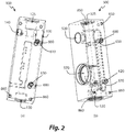
Figure 2 shows a front perspective view of the first type of probe-holding module (Fig. 2a ) and a rear perspective view of the fifth type of probe-holding module (Fig. 2b ) ofFigure 1 ; -
Figure 3 shows a front view (Fig. 3a ) and a cross-section view along the plane AA ofFigure 3a (Fig. 3b ) of a first assembly of four of the probe-holding modules ofFigure 1 ; -
Figure 4 shows a first cross-section view (Fig. 4a ) and a second cross-section view (Fig. 4b ) of a particular of a coupling zone between two probe-holding modules ofFigure 1 , wherein each view represents specific features of the coupling; -
Figure 5 shows a left side view of the fifth type of probe-holding module (Fig. 5a ) ofFigure 1 and a cross-section view (Fig. 5b ) of a particular of a coupling zone between two probe-holding modules ofFigure 1 ; -
Figure 6 shows a front view (Fig. 6a ) and a cross-section view along the plane BB ofFigure 6a (Fig. 6b ) of an assembly of four probe-holding modules of another modular probe-holder to which the first embodiment of the probe-holder for amperometric sensor according to the invention is applied; -
Figure 7 shows a cross-section view (Fig. 7a ) of the first assembly ofFigure 3 wherein each probe-holding module houses a respective sensing probe, an enlargement of the cross-section view (Fig. 7b ) and a perspective view of a component coupled to the first assembly (Fig. 7c ); -
Figure 8 shows a rear perspective view of a second assembly of two of the probe-holding modules ofFigure 1 wherein each probe-holding module houses a respective sensing probe; -
Figure 9 shows a cross-section view of the first type of probe-holding module ofFigure 1 ; and -
Figure 10 shows an enlargement of a portion of the cross-section of the first assembly ofFigure 7 (Fig. 10a ), a cross-section view along the plane CC ofFigure 10a (Fig. 10b ) and two enlargements of the same particular ofFigure 10b (Fig. 10c and Fig. 10d ), wherein each enlargement represents specific features of the particular. - In the Figures identical reference numerals will be used for alike elements.
- With reference to
Figures 1 and2 , it may be observed that a first embodiment of the probe-holder for amperometric sensor according to the invention is a probe-holding module for amperometric sensor applied to a modular probe-holder that may be composed of two or more probe-holding modules coupled to each other the type of which is selected from a group comprising five types of different probe-holding modules, each one made in one piece of plexiglass that can be inscribed in a substantially parallelepiped-shaped polyhedron, and capable to be coupled to each other. - A first type of probe-
holding module 100, shown inFigures 1a and2a , is configured to house an adjustable flow meter, optionally capable to measure a volumetric flow rate ranging from 10 to 100 litres/hour. The first probe-holding module 100 comprises a longitudinal central duct (i.e., a vertical central duct) 110 that communicates externally through a lower threadedmouth 120, through an upper hollow threadedseat 125 and through an upper right side threaded outlet 130 ("right side" with respect to the front view of the first probe-holding module 100) connected to the longitudinalcentral duct 110 through an upper right transverse duct 135. Moreover, the first probe-holding module 100 is provided with an upper left sidehollow seat 140 and a rearhollow seat 150. - A second type of probe-
holding module 200, shown inFigure 1b , is configured to house a sensing probe and comprises a longitudinalcentral duct 210 having a first diameter, optionally equal to 12 mm, that communicates externally through a lower threadedmouth 220, through an upper hollow threadedseat 225 and through an upper right side threaded outlet 230 ("right side" with respect to the front view of the second probe-holding module 200) connected to the longitudinalcentral duct 210 through an upper righttransverse duct 235. Moreover, the second probe-holding module 200 is provided with agroove 260 on the left side wall that communicates with the longitudinalcentral duct 210 through a lower lefttransverse duct 265. - A third type of probe-
holding module 300, shown inFigure 1c , is configured to house a sensing probe and comprises a longitudinalcentral duct 310 having a second diameter larger than the first diameter, optionally equal to 24 mm, that communicates externally through a lower threadedmouth 320, through an upper hollow threadedseat 325 and through an upper right side threaded outlet 330 ("right side" with respect to the front view of the third probe-holding module 300). Moreover, the third probe-holding module 300 is provided with agroove 360 on the left side wall that communicates with the longitudinalcentral duct 310 through a lower lefttransverse duct 365. - A fourth type of probe-
holding module 400, shown inFigure 1d , is configured to house a sensing probe and comprises a longitudinalcentral duct 410 having a third diameter larger than the second diameter, optionally equal to 35 mm, that communicates externally through a lower threadedmouth 420, through an upper hollow threadedseat 425 and through an upper right side threaded outlet 430 ("right side" with respect to the front view of the fourth probe-holding module 400). Moreover, the fourth probe-holdingmodule 400 is provided with agroove 460 on the left side wall that communicates with the longitudinalcentral duct 410 through a lower lefttransverse duct 465. - The probe-holding module for amperometric sensor according to the invention is a fifth type of probe-holding
module 500, shown inFigures 1e and2b , that is configured to house a horizontal amperometric sensor in a lower right sidehollow seat 570 communicating inferiorly with a lower threadedmouth 520, in turn communicating externally, and superiorly with alongitudinal duct 510, in turn communicating externally through an upper hollow threadedseat 525 and through an upper right side threaded outlet 530 ("right side" with respect to the front view of the fifth probe-holding module 500). Moreover, the fifth probe-holdingmodule 500 is provided with agroove 560 on the left side wall that communicates with the lower right sidehollow seat 570 through a lower lefttransverse duct 565. - The fastening of the probe-holding modules is guaranteed by ties constrained in the probe-holding modules operated by grub screws, allowing the coupling between probe-holding modules without constraints of consecutiveness apart from the first type of probe-holding
module 100 that, in the modular probe-holders shown in the Figures to which the first embodiment of the probe-holder for amperometric sensor according to the invention, must be always the first module of the series of assembled modules which form the modular probe-holder and apart from the fifth type of probe-holdingmodule 500 that, in the modular probe-holders shown in the Figures to which the first embodiment of the probe-holder for amperometric sensor according to the invention is applied, must be always the last module of the series of assembled modules which form the modular probe-holder. - To this end, the second, the third and the fourth type of probe-holding
modules holes 600 communicating with a pair of respective upperleft side seats 650 communicating externally and having longitudinal axis orthogonal to the axis of the respective threadedhole 600, a pair of upper right threadedholes 610 communicating with a pair of respective upper right side seats 660 communicating externally and having longitudinal axis orthogonal to the axis of the respective threadedhole 610, a pair of lower left threadedholes 620 communicating with a pair of respective lowerleft side seats 670 communicating externally and having longitudinal axis orthogonal to the axis of the respective threadedhole 620, and a pair of lower right threadedholes 630 communicating with a pair of respective lower right side seats 680 communicating externally and having longitudinal axis orthogonal to the axis of the respective threadedhole 630; each one of the threaded holes is configured to receive a grub screw, while each one of the seats communicating with the threaded holes is configured to partially receive a tie. - The first type of probe-holding
module 100 is provided on the front and rear walls with only the pair of upper right threadedholes 610 and the pair of lower right threadedholes 630, each one of which is also configured to receive a grub screw, communicating with respective upper and lower right side seats 660 and 680, each one of which is also configured to partially receive a tie. - The fifth type of probe-holding
module 500 is provided on walls front and rear walls with only the pair of upper left threadedholes 600 and the pair of lower left threadedholes 620, each one of which is also configured to receive a grub screw, communicating with respective upper and lowerleft side seats - However, it should be understood that other embodiments of the probe-holder for amperometric sensor according to the invention may consist of a probe-holding module for amperometric sensor, for instance a horizontal amperometric sensor housed in a front hollow seat or a vertical amperometric sensor housed in a corresponding seat, that may be coupled to other modules in any position along the series of assembled modules forming the modular probe-holder (i.e. not necessarily placed as last module); in this case, such probe-holding modules configured to house amperometric sensors are provided with the same assembly of pairs of threaded
holes seats modules - Moreover, other modular probe-holders may have probe-holding modules configured to house flow meters which may be coupled to other modules in any position along the series of assembled modules forming the modular probe-holder (i.e. not necessarily placed as first module); such probe-holding modules configured to house flow meters are also provided with the same assembly of pairs of threaded
holes seats modules - With reference to
Figure 3 , wherein by way of example and not by way of limitation a modular probe-holder constituted of an ordered series of a first type, a second type, a third type and a fifth type of probe-holdingmodules ties 700 are inserted into the pairs of facingside seats grub screws 710 are screwed into the threadedholes - In order to better understand the operation of the
grub screws 700 andties 710 reference can be made toFigure 4 , wherein an enlargement of a cross-section of a coupling zone of two adjacent probe-holding modules (generically indicated with thereference numerals 10 and 20) comprising atie 700 inserted into a pair of corresponding facing side seats is shown. Thetie 700 comprises twoholes 701 each configured to receive thetip 711 of agrub screw 710 screwed into a respective threaded hole (the threaded holes are generically indicated with thereference numerals 15 and 25). In particular, thetip 711 of a grub screw has a conical lateral surface, optionally with apex angle equal to 90° (whereby the side surface has an inclination of 45° with respect to the longitudinal axis of the grub screw 710), and thehole 701 and tie 700 have a corresponding support inclined surface, optionally with inclination of 45° with respect to the longitudinal axis of thehole 701. - The area of contact between
tip 711 of thegrub screw 710 andhole 701 of thetie 700 only comprises the portion of the support inclined surface of thehole 701 of thetie 700 that is farthest from the adjacent probe-holding module (20 or 10). To this end, when thetie 700 is symmetrically arranged in the pair of corresponding facing side seats, there is an offset between the longitudinal axis of each one of the threadedholes 15 and 20 (coinciding with the longitudinal axis of thegrub screw 710 inserted into such threaded hole) and the longitudinal axis of thehole 701 of thetie 700; optionally, when the two adjacent probe-holdingmodules holes 15 and 20 (communicating with the pair of side seats facing the two adjacent probe-holdingmodules 10 and 20) is larger than the distance DB between the longitudinal axes of theholes 701 of thetie 700, optionally by an amount ranging from 2% to 3%, more optionally by an amount equal to 2,5% (whereby DA=1,025*DB). - When a
grub screw 710 is screwed into the respective threaded hole (15 or 25), it advances longitudinally (along the direction of the arrow A) exerting a force (along the direction of the arrow B) perpendicular to the support surface of therespective hole 701 of thetie 700. The preferred inclination angle of the side surface of thetip 711 of the grub screw, equal to 45°, maximises the area of contact betweentip 711 of thegrub screw 710 andhole 701 of thetie 700 dedicated to the transmission of forces. The horizontal component of such force produces a constraint reaction (along the direction of the arrow C) on the portion of the surface of the threaded hole (15 or 25) closest to the adjacent probe-holding module (20 or 10), causing the two adjacent probe-holdingmodules - With reference to
Figures 2b and5a , wherein by way of example and not by way of limitation a probe-holdingmodule 500 of the fifth type configured to house an amperometric sensor (that constitutes the first embodiment of the probe-holder for amperometric sensor according to the invention) is shown, it may be observed that on the left side wall of the probe-holding modules is present aseal groove 800 arranged so as to surround thegroove 560 of the probe-holdingmodule 500 and, when the latter is coupled to an adjacent probe-holding module (100, 200, 300 or 400), also the upper left side outlet (130, 230, 330 or 430) on the left side wall of the adjacent probe-holding module (100, 200, 300 or 400). Theseal groove 800 is configured to house an O-ring seal 810 of elastic material, optionally of fluoroelastomer known as FPM or FKM, with optionally circular cross-section, whereby theseal 810 is capable to ensure the sealing of the coupling between adjacent probe-holding modules since it surrounds the path of the fluid when passing from one to the other of the two adjacent probe-holding modules. - As shown in
Figure 5b , wherein an enlargement of a cross-section of a coupling zone of two adjacent probe-holding modules (generically indicated with thereference numerals 10 and 20) comprising agroove 800 housing aseal 810 is shown, the geometry and size of thegroove 800 and seal 810 are such that they guarantee the compression of theseal 810 when the two adjacent probe-holdingmodules modules seal 810 ensures the correct operation of the modular probe-holder with both fluid in static conditions and moving flow under several operation conditions, for instance at a first condition with fluid temperature of 25°C and fluid pressure of 10 bar and at a second condition with fluid temperature of 70°C and fluid pressure of 7 bar. Advantageously, the deformation of theseal 810 mainly concerns the direction orthogonal to the walls of contact of two adjacent probe-holdingmodules groove 800 has rectangular cross-section, with depth p and width w equal to the diameter w of theseal 810 with circular cross-section, wherein p ranges from 65% to 75% of w (whereby 0.65*w ≤ p ≤ 0,7*w), p being more optionally equal to 70% of w (whereby p=0,7*w). In this case, even when the single probe-holding modules provided with the seal housed in the groove are disassembled, the seal stably remains in the groove even if the module is moved. In other words, the sealing effect is given by the deformation of theseal 810 during fastening of two adjacent probe-holdingmodules grub screws 710 and the absence of vibrations during the operation of the modular probe-holder do not render the use of self-locking devices necessary and ensure the compression imposed to theseal 810 for the entire lifetime of the modular probe-holder. Optionally, the hardness of the seal is not lower than 50 shore A (SHA), more optionally not lower than 60 SHA, in order to avoid that the seal is extruded between the walls of the two adjacent probe-holdingmodules - In the modular probe-holders shown in the Figures to which the first embodiment of the probe-holder for amperometric sensor according to the invention is applied, since the first type of probe-holding
module 100 is the first module of the series of assembled modules forming the modular probe-holder, such first type of probe-holdingmodule 100 is not provided on the left side wall with theseal groove 800. - Other modular probe-holders may have the probe-holding modules having a seal groove on the right side wall, instead of the left side wall, still arranged so as to surround the path of the fluid when passing from one to the other of the two adjacent probe-holding modules. In the case where the fifth type of probe-holding
module 500 is still always the last module of the series of assembled modules forming a modular probe-holder, such fifth type of probe-holdingmodule 500 would not be provided on the right side wall with such seal groove. - Further modular probe-holders may have the probe-holding modules which have a seal groove on both the left side wall and the right side wall, configured such that they do not overlap with the seal groove respectively on the right side wall and the left side wall of two other adjacent modules, both the seal grooves on the two side walls being arranged so as to surround the path of the fluid when passing from one to the other of the two adjacent probe-holding modules.
- It should be understood that the specific arrangement of the seal groove configured to house an O-ring seal, illustrated with reference to
Figures 2b and5 , is not a feature essential to the probe-holder for amperometric sensor according to the invention, that may be made as monolithic probe-holder configured to house only an amperometric sensor or to house an amperometric sensor and one or more further sensing probes, optionally in respective housings communicating with each other. - It should be further understood that the mechanical means for coupling two probe-holding modules is not a feature essential to the probe-holder for amperometric sensor according to the invention, and it can be different from that illustrated with reference to the Figures also in function of the type, shape and size of the modules which have to be coupled. By way of example, and not by way of limitation, such coupling mechanical means may also comprise or consist of at least one flange and/or rivets and/or screws and bolts.
- By way of example, reference to
Figure 6 , it may be observed that the coupling mechanical means used in another modular probe-holder, to which the first embodiment of the probe-holder for amperometric sensor according to the invention, comprises, instead of grub screws and ties, threadedstuds 750 screwed in suitable transverse through holes (operating as side seats) accessible on the side walls of the single probe-holding modules. Differently from the solution adopted in the modular probe-holder shown inFigure 3 and4 , the coupling through threadedstuds 750 imposes that, in order to access a probe-holding module of a series of assembled modules forming the modular probe-holder, it is necessary to disassemble all the subsequent probe-holding modules. -
Figure 7 , wherein by way of example and not by way of limitation a modular probe-holder constituted by an ordered series of a first type, a second type, a third type and a fifth type of probe-holdingmodule Figures 1 and2 ) is shown, each one of which houses a respective sensing probe, shows the path of the water flow (schematically represented by the arrows inFigure 7 ) in the modular probe-holder to which the first embodiment of the probe-holder for amperometric sensor according to the invention is applied. In particular, the entrance of the water flow in the modular probe-holder occurs through a tube-holder 900 coupled in the lower threadedmouth 120 of the first probe-holdingmodule 100. Thelongitudinal ducts modules right side outlets modules left side walls Figure 7b related to the passage from the second probe-holdingmodule 200 to the third probe-holdingmodule 300. The flow exiting from the last probe-holding module of the series, that inFigure 7 is the fifth probe-holdingmodule 500, is channelled by screwing a tube-holder 910 (shown enlarged inFigure 7c ) into the upper right side outlet. The lower threadedmouths modules mouths modules caps 920 andother devices 930 and 940 (e.g. electrodes and taps), whereby they do not provide the flow shown inFigure 7 with other exits. - Making reference again to
Figures 1 and2 , all the probe-holding modules are provided, on the rear wall, with a pair of upper rear threadedholes 850 and with a pair of lower rear threadedholes 860 configured to receive a screw for fastening rear brackets allowing the modular probe-holder to be fixed to a wall or support plate. Such rear brackets are fixed to the probe-holding modules at the ends of the series of assembled modules forming the modular probe-holder. By way of example, and not by way of limitation,Figure 8 shows a modular probe-holder constituted by a first type and a fifth type of probe-holdingmodules rear brackets 950 have been fixed throughscrews 960 inserted into the rear threadedholes rear brackets 950 are provided withholes 955 for the fastening through conventional means, such as Fischer plugs, to a wall or support plate. - The probe-holding modules allow to make modular probe-holders having any configuration.
- The probe-holding
module 100 of the first type is configured to house a flow meter dedicated to the measure of volumetric flow rate, optionally indicated by a suitably calibrated graduated scale present on the front wall of the probe-holdingmodule 100. Making reference toFigure 9 , it may be observed that afloat 1100, optionally of plastic material, is advantageously inserted into the longitudinalcentral duct 110, that is provided with apermanent magnet 1110 configured to interact with aReed switch 1120 housed in the rearhollow seat 150 of the probe-holdingmodule 100; in particular, theReed switch 1120 is actuated by the permanent magnet 1110 (that is inserted into the float 1100) when the volumetric flow rate has a value in a predetermined range, optionally ranging from 60 l/h to 80 l/h. - Other modular probe-holder according to the invention may comprise, instead of the
Reed switch 1120, a different proximity sensor interacting with thefloat 1100, such as for instance a Hall effect sensor, that senses when the volumetric flow rate at the inlet of the modular probe-holder is not within a predetermined range even different from that ranging from 60 l/h to 80 l/h, optionally a predetermined range ranging from 60 l/h to 100 l/h. - As shown in
Figures 10a and 10b , the probe-holdingmodule 500 of the fifth type, that constitutes the first embodiment of the probe-holder for amperometric sensor according to the invention, is configured to house ahorizontal amperometric sensor 970 in the lower right sidehollow seat 570, having a circular or ellipsoidal transverse section (as shown inFigure 10b ), that inferiorly communicates with the lower threadedmouth 520 through a plurality of inner tubular ducts 575 (in the preferred embodiment ofFigure 10 , such innertubular ducts 575 are seven, arranged along two rows visible inFigures 10c and 10d as aligned sideways, of which theoutlet mouths 975 are visible inFigure 10a in the lower right side hollow seat 570), the diameter of which (optionally equal to 2 mm) is significantly lower than its length (optionally equal to 12 mm). - The probe-holding
module 500, that constitutes the first embodiment of the probe-holder for amperometric sensor according to the invention, is provided with an upper left transverse duct 580 (that is optionally tubular) that, in correspondence with the upper right side threadedoutlet 330 of theadjacent module 300, puts in communication the upper portion of thegroove 560 on the left side wall with the upper portion of thelongitudinal duct 510. Such upper left transverse duct 580 allows the air present in the fluid entering thegroove 560 on the left side wall to be eliminated by the Venturi effect; in other words, the upper left transverse duct 580 operates as by-pass for air mixed with the fluid entering the fifth probe-holdingmodule 500. In this way, the upper left transverse duct 580 achieves a degassing of the fluid entering the fifth probe-holdingmodule 500 that is particularly important for avoiding malfunctions of theamperometric sensor 970; in particular, the amount of air mixed with the fluid is larger when the fluid starts to flow in the modular probe-holder. - As shown in greater detail in
Figures 10c and 10d , the water flow (schematically represented inFigure 10d by the arrows) in the probe-holding module 500 (that constitutes the first embodiment of the probe-holder for amperometric sensor according to the invention) is channelled from the bottom upwards in the lower right sidehollow seat 570 through the innertubular ducts 575 each having an inclination angle α, with respect to the transverse plane crossing the right and left side walls of the probe-holdingmodule 500, optionally ranging from 20° to 30°, more optionally equal to 25°. This channelling, by accelerating the flow, allows the solute to be agitated and further guarantees the entrainment of the balls (optionally of plastics, glass or ceramic, not shown) housed in the lower right sidehollow seat 570 for cleaning the electrode of the amperometric sensor. Moreover, the lower right sidehollow seat 570 communicates superiorly with thelongitudinal duct 510, through a plurality (Figure 10 shows three) of planar ducts 515 (i.e. having a dimension much lower than the other two), oriented parallel to the longitudinal axis of the longitudinal duct 510 (and optionally orthogonally to the transverse plane crossing the right and left side walls of the probe-holding module 500). - In particular, the orientation of the
longitudinal duct 510 in vertical direction is not a feature essential to the probe-holder for amperometric sensor according to the invention. - The upper left transverse duct 580 is not a feature essential to the probe-holder for amperometric sensor according to the invention. In particular, the probe-holder for amperometric sensor according to the invention may comprise any transverse duct, connected between an inlet of the probe-holder and the longitudinal duct, that operates as by-pass for air mixed with the fluid entering the probe-holder.
- Similarly, the
planar ducts 515 are not a feature essential to the probe-holder for amperometric sensor according to the invention, and they may be replaced with any other structure of ducts. - Also, the specific arrangement of the
groove 560, the lower lefttransverse duct 565 and the lower threadedmouth 520, communicating with each other, is not a feature essential to the probe-holder for amperometric sensor according to the invention. In particular, such specific arrangement may be generalised as any space (that may also comprise or consist of one or more ducts shaped anyway) connected downstream of an inlet of the probe-holder for amperometric sensor according to the invention and upstream of a side hollow seat (that may be located on the right or left or even frontally), that is configured to house an amperometric sensor, that communicates with such side hollow seat through internal tubular ducts similar to theducts 575 connecting the lower threadedmouth 520 to the lower sidehollow seat 570 shown inFigure 10 . - Furthermore, the
groove 560 is not a feature essential to the probe-holder for amperometric sensor according to the invention, and it may be replaced with any type of inlet. - Again, it should be understood that the specific arrangement of the internal
tubular ducts 575, illustrated with reference toFigure 10 , is also applicable (even independently from the arrangement of the upper left transverse duct 580) to other embodiments of the probe-holder for amperometric sensor according to the invention different from the first embodiment shown in the Figures. By way of example, and not by way of limitation, such arrangement of the internaltubular ducts 575 may be applied in a monolithic probe-holder for amperometric sensor, that is configured to house only an amperometric sensor or to house an amperometric sensor and one or more further sensing probes, optionally in respective housings communicating with each other. - The preferred embodiments of this invention have been described and a number of variations have been suggested hereinbefore, but it should be understood that those skilled in the art can make other variations and changes, without so departing from the scope of protection thereof, as defined by the attached claims.
Claims (9)
- Probe-holder (500), having a first and a second side walls, configured to house an amperometric sensor (970) in a side hollow seat (570), the probe-holder comprising an inlet (560) and an outlet (530) and a longitudinal duct (510) connected downstream of the side hollow seat (570), the probe-holder (500) being configured to receive a flow of a fluid from the inlet (560) to the outlet (530), the probe-holder (500) further comprising a space (520) downstream of the inlet (560) and upstream of the side hollow seat (570), the probe-holder (500) being characterised in that the space (520) is connected to the side hollow seat (570) through a plurality of two or more inner tubular ducts (575) inclined by an inclination angle α with respect to a transversal plane crossing the first and second side walls of the probe-holder (500).
- Probe-holder (500) according to claim 1, characterised in that the inclination angle α of each inner tubular duct (575) with respect to said transversal plane ranges from 20° to 30°.
- Probe-holder (500) according to claim 2, characterised in that the inclination angle α of each inner tubular duct (575) with respect to said transversal plane is equal to 25°.
- Probe-holder (500) according to any one of the preceding claims, characterised in that the side hollow seat (570) is connected to the longitudinal duct (510) through one or more planar ducts (515) oriented parallel to a longitudinal axis of the longitudinal duct (510).
- Probe-holder (500) according to claim 4, characterised in that said one or more planar ducts (515) are oriented orthogonally to said transversal plane crossing the right and left walls of the probe-holder (500).
- Probe-holder (500) according to any one of the preceding claims, characterised in that the space comprises a, optionally threaded, mouth (520) communicating externally.
- Probe-holder (500) according to claim 6, characterised in that the mouth (520) is connected to the inlet (560) through a transversal duct (565).
- Probe-holder (500) according to any one of the preceding claims, characterised in that it further comprises a transversal duct (580) connected between the inlet of the probe-holder and the longitudinal duct (510), whereby the transversal duct (580) is configured to operate as by-pass for air mixed with said incoming fluid entering the probe-holder (500).
- Probe-holder (500) according to any one of the preceding claims, characterised in that the longitudinal duct (510) is vertical, the side hollow seat (570) is arranged inferiorly to the longitudinal duct (510) and the outlet (530) of the probe-holder (500) is superiorly arranged on a side wall selected between the first and the second side walls, whereby the longitudinal duct (510) is configured to receive said flow of a fluid from the bottom upwards.
Priority Applications (1)
| Application Number | Priority Date | Filing Date | Title |
|---|---|---|---|
| PL14714352T PL2956766T3 (en) | 2013-02-18 | 2014-02-18 | Probe-holder for amperometric sensor |
Applications Claiming Priority (2)
| Application Number | Priority Date | Filing Date | Title |
|---|---|---|---|
| IT000093A ITRM20130093A1 (en) | 2013-02-18 | 2013-02-18 | PROBE HOLDER FOR AMPEROMETRIC SENSOR |
| PCT/IB2014/059062 WO2014125456A2 (en) | 2013-02-18 | 2014-02-18 | Probe-holder for amperometric sensor |
Publications (2)
| Publication Number | Publication Date |
|---|---|
| EP2956766A2 EP2956766A2 (en) | 2015-12-23 |
| EP2956766B1 true EP2956766B1 (en) | 2017-08-02 |
Family
ID=48145600
Family Applications (1)
| Application Number | Title | Priority Date | Filing Date |
|---|---|---|---|
| EP14714352.3A Active EP2956766B1 (en) | 2013-02-18 | 2014-02-18 | Probe-holder for amperometric sensor |
Country Status (8)
| Country | Link |
|---|---|
| EP (1) | EP2956766B1 (en) |
| DK (1) | DK2956766T3 (en) |
| ES (1) | ES2637720T3 (en) |
| HU (1) | HUE034909T2 (en) |
| IT (1) | ITRM20130093A1 (en) |
| PL (1) | PL2956766T3 (en) |
| PT (1) | PT2956766T (en) |
| WO (1) | WO2014125456A2 (en) |
Families Citing this family (1)
| Publication number | Priority date | Publication date | Assignee | Title |
|---|---|---|---|---|
| CN111103444A (en) * | 2018-10-29 | 2020-05-05 | 三赢科技(深圳)有限公司 | Detection device |
Family Cites Families (4)
| Publication number | Priority date | Publication date | Assignee | Title |
|---|---|---|---|---|
| JPS506397A (en) * | 1972-12-11 | 1975-01-23 | ||
| EP1366354A2 (en) * | 2001-03-07 | 2003-12-03 | Instrumentation Laboratory Company | Reference electrode |
| EP1397695A1 (en) * | 2001-06-08 | 2004-03-17 | Biolab Services, Inc. | Self-cleaning probe system |
| FR2969296B1 (en) * | 2010-12-20 | 2013-06-28 | Dominique Ducoeur | DEVICE FOR CONTROLLING THE OXIDIZING POWER OF A MASS OF WATER, ESPECIALLY APPLYING TO THE WATER OF A SWIMMING POOL |
-
2013
- 2013-02-18 IT IT000093A patent/ITRM20130093A1/en unknown
-
2014
- 2014-02-18 DK DK14714352.3T patent/DK2956766T3/en active
- 2014-02-18 ES ES14714352.3T patent/ES2637720T3/en active Active
- 2014-02-18 EP EP14714352.3A patent/EP2956766B1/en active Active
- 2014-02-18 HU HUE14714352A patent/HUE034909T2/en unknown
- 2014-02-18 PL PL14714352T patent/PL2956766T3/en unknown
- 2014-02-18 PT PT147143523T patent/PT2956766T/en unknown
- 2014-02-18 WO PCT/IB2014/059062 patent/WO2014125456A2/en not_active Ceased
Non-Patent Citations (1)
| Title |
|---|
| None * |
Also Published As
| Publication number | Publication date |
|---|---|
| HUE034909T2 (en) | 2018-03-28 |
| WO2014125456A3 (en) | 2014-11-20 |
| ITRM20130093A1 (en) | 2014-08-19 |
| PT2956766T (en) | 2017-08-25 |
| ES2637720T3 (en) | 2017-10-16 |
| PL2956766T3 (en) | 2017-12-29 |
| WO2014125456A2 (en) | 2014-08-21 |
| EP2956766A2 (en) | 2015-12-23 |
| DK2956766T3 (en) | 2017-09-04 |
Similar Documents
| Publication | Publication Date | Title |
|---|---|---|
| EP2956770B1 (en) | Modular probe-holder | |
| US11402248B2 (en) | Flow sensor devices and systems | |
| US7454984B1 (en) | Flow meter for measuring a flow rate of a flow of a fluid | |
| US8443842B2 (en) | Flow straightener for a flowmeter, in particular an ultrasonic metering device | |
| US9372105B2 (en) | Ultrasonic flow rate measurement device | |
| ES2950657T3 (en) | Flow measurement | |
| US7905142B2 (en) | Servo type volumetric flowmeter employing a pump unit system | |
| US9423367B2 (en) | Permeable measuring cell for receiving measuring means | |
| EP2124022B1 (en) | Path structure for flow and differential-pressure detections in servo-type displacement flowmeter | |
| KR20150098586A (en) | Differentail pressure type flowmeter and flow rate controller having the same | |
| DK2956766T3 (en) | SOUND HOLDER FOR AMPEROMETRIC SENSOR | |
| JP6306434B2 (en) | Ultrasonic flow meter | |
| JP6677486B2 (en) | Ultrasonic flow meter | |
| CN103968896A (en) | Small-flow outcrop spring flow measuring device | |
| JP5266089B2 (en) | Fluid measuring device | |
| WO2014125458A1 (en) | Mechanical coupling assembly | |
| JPH08122112A (en) | Flowmeter | |
| ITRM20130092A1 (en) | PROBE HOLDER FOR FLOWMETER WITH FLOW REGULATOR | |
| KR200321445Y1 (en) | apparatus for measuring the amount of flowing water using ultrasonic sensor | |
| EP4339166A1 (en) | Chlorinator | |
| CN219675637U (en) | Dilution device | |
| JP6646414B2 (en) | Ultrasonic flow meter | |
| SU1746223A1 (en) | Vortex-type flowmeter | |
| CN113899411A (en) | Bidirectional rotor flow meter | |
| JP2003270021A (en) | Straightener |
Legal Events
| Date | Code | Title | Description |
|---|---|---|---|
| PUAI | Public reference made under article 153(3) epc to a published international application that has entered the european phase |
Free format text: ORIGINAL CODE: 0009012 |
|
| 17P | Request for examination filed |
Effective date: 20150916 |
|
| AK | Designated contracting states |
Kind code of ref document: A2 Designated state(s): AL AT BE BG CH CY CZ DE DK EE ES FI FR GB GR HR HU IE IS IT LI LT LU LV MC MK MT NL NO PL PT RO RS SE SI SK SM TR |
|
| AX | Request for extension of the european patent |
Extension state: BA ME |
|
| DAX | Request for extension of the european patent (deleted) | ||
| GRAP | Despatch of communication of intention to grant a patent |
Free format text: ORIGINAL CODE: EPIDOSNIGR1 |
|
| INTG | Intention to grant announced |
Effective date: 20170109 |
|
| GRAS | Grant fee paid |
Free format text: ORIGINAL CODE: EPIDOSNIGR3 |
|
| GRAJ | Information related to disapproval of communication of intention to grant by the applicant or resumption of examination proceedings by the epo deleted |
Free format text: ORIGINAL CODE: EPIDOSDIGR1 |
|
| GRAL | Information related to payment of fee for publishing/printing deleted |
Free format text: ORIGINAL CODE: EPIDOSDIGR3 |
|
| GRAP | Despatch of communication of intention to grant a patent |
Free format text: ORIGINAL CODE: EPIDOSNIGR1 |
|
| INTC | Intention to grant announced (deleted) | ||
| GRAA | (expected) grant |
Free format text: ORIGINAL CODE: 0009210 |
|
| INTG | Intention to grant announced |
Effective date: 20170614 |
|
| AK | Designated contracting states |
Kind code of ref document: B1 Designated state(s): AL AT BE BG CH CY CZ DE DK EE ES FI FR GB GR HR HU IE IS IT LI LT LU LV MC MK MT NL NO PL PT RO RS SE SI SK SM TR |
|
| REG | Reference to a national code |
Ref country code: CH Ref legal event code: EP Ref country code: AT Ref legal event code: REF Ref document number: 915025 Country of ref document: AT Kind code of ref document: T Effective date: 20170815 |
|
| REG | Reference to a national code |
Ref country code: RO Ref legal event code: EPE |
|
| REG | Reference to a national code |
Ref country code: IE Ref legal event code: FG4D |
|
| REG | Reference to a national code |
Ref country code: PT Ref legal event code: SC4A Ref document number: 2956766 Country of ref document: PT Date of ref document: 20170825 Kind code of ref document: T Free format text: AVAILABILITY OF NATIONAL TRANSLATION Effective date: 20170816 |
|
| REG | Reference to a national code |
Ref country code: NL Ref legal event code: FP |
|
| REG | Reference to a national code |
Ref country code: DK Ref legal event code: T3 Effective date: 20170901 |
|
| REG | Reference to a national code |
Ref country code: DE Ref legal event code: R096 Ref document number: 602014012535 Country of ref document: DE |
|
| REG | Reference to a national code |
Ref country code: ES Ref legal event code: FG2A Ref document number: 2637720 Country of ref document: ES Kind code of ref document: T3 Effective date: 20171016 |
|
| REG | Reference to a national code |
Ref country code: LT Ref legal event code: MG4D |
|
| PG25 | Lapsed in a contracting state [announced via postgrant information from national office to epo] |
Ref country code: LT Free format text: LAPSE BECAUSE OF FAILURE TO SUBMIT A TRANSLATION OF THE DESCRIPTION OR TO PAY THE FEE WITHIN THE PRESCRIBED TIME-LIMIT Effective date: 20170802 Ref country code: SE Free format text: LAPSE BECAUSE OF FAILURE TO SUBMIT A TRANSLATION OF THE DESCRIPTION OR TO PAY THE FEE WITHIN THE PRESCRIBED TIME-LIMIT Effective date: 20170802 Ref country code: HR Free format text: LAPSE BECAUSE OF FAILURE TO SUBMIT A TRANSLATION OF THE DESCRIPTION OR TO PAY THE FEE WITHIN THE PRESCRIBED TIME-LIMIT Effective date: 20170802 Ref country code: NO Free format text: LAPSE BECAUSE OF FAILURE TO SUBMIT A TRANSLATION OF THE DESCRIPTION OR TO PAY THE FEE WITHIN THE PRESCRIBED TIME-LIMIT Effective date: 20171102 |
|
| REG | Reference to a national code |
Ref country code: FR Ref legal event code: PLFP Year of fee payment: 5 |
|
| PG25 | Lapsed in a contracting state [announced via postgrant information from national office to epo] |
Ref country code: BG Free format text: LAPSE BECAUSE OF FAILURE TO SUBMIT A TRANSLATION OF THE DESCRIPTION OR TO PAY THE FEE WITHIN THE PRESCRIBED TIME-LIMIT Effective date: 20171102 Ref country code: IS Free format text: LAPSE BECAUSE OF FAILURE TO SUBMIT A TRANSLATION OF THE DESCRIPTION OR TO PAY THE FEE WITHIN THE PRESCRIBED TIME-LIMIT Effective date: 20171202 Ref country code: GR Free format text: LAPSE BECAUSE OF FAILURE TO SUBMIT A TRANSLATION OF THE DESCRIPTION OR TO PAY THE FEE WITHIN THE PRESCRIBED TIME-LIMIT Effective date: 20171103 Ref country code: RS Free format text: LAPSE BECAUSE OF FAILURE TO SUBMIT A TRANSLATION OF THE DESCRIPTION OR TO PAY THE FEE WITHIN THE PRESCRIBED TIME-LIMIT Effective date: 20170802 Ref country code: LV Free format text: LAPSE BECAUSE OF FAILURE TO SUBMIT A TRANSLATION OF THE DESCRIPTION OR TO PAY THE FEE WITHIN THE PRESCRIBED TIME-LIMIT Effective date: 20170802 |
|
| REG | Reference to a national code |
Ref country code: HU Ref legal event code: AG4A Ref document number: E034909 Country of ref document: HU |
|
| REG | Reference to a national code |
Ref country code: DE Ref legal event code: R097 Ref document number: 602014012535 Country of ref document: DE |
|
| PG25 | Lapsed in a contracting state [announced via postgrant information from national office to epo] |
Ref country code: SK Free format text: LAPSE BECAUSE OF FAILURE TO SUBMIT A TRANSLATION OF THE DESCRIPTION OR TO PAY THE FEE WITHIN THE PRESCRIBED TIME-LIMIT Effective date: 20170802 Ref country code: EE Free format text: LAPSE BECAUSE OF FAILURE TO SUBMIT A TRANSLATION OF THE DESCRIPTION OR TO PAY THE FEE WITHIN THE PRESCRIBED TIME-LIMIT Effective date: 20170802 Ref country code: SM Free format text: LAPSE BECAUSE OF FAILURE TO SUBMIT A TRANSLATION OF THE DESCRIPTION OR TO PAY THE FEE WITHIN THE PRESCRIBED TIME-LIMIT Effective date: 20170802 |
|
| PLBE | No opposition filed within time limit |
Free format text: ORIGINAL CODE: 0009261 |
|
| STAA | Information on the status of an ep patent application or granted ep patent |
Free format text: STATUS: NO OPPOSITION FILED WITHIN TIME LIMIT |
|
| 26N | No opposition filed |
Effective date: 20180503 |
|
| PG25 | Lapsed in a contracting state [announced via postgrant information from national office to epo] |
Ref country code: SI Free format text: LAPSE BECAUSE OF FAILURE TO SUBMIT A TRANSLATION OF THE DESCRIPTION OR TO PAY THE FEE WITHIN THE PRESCRIBED TIME-LIMIT Effective date: 20170802 |
|
| REG | Reference to a national code |
Ref country code: BE Ref legal event code: MM Effective date: 20180228 |
|
| PG25 | Lapsed in a contracting state [announced via postgrant information from national office to epo] |
Ref country code: BE Free format text: LAPSE BECAUSE OF NON-PAYMENT OF DUE FEES Effective date: 20180228 |
|
| REG | Reference to a national code |
Ref country code: AT Ref legal event code: UEP Ref document number: 915025 Country of ref document: AT Kind code of ref document: T Effective date: 20170802 |
|
| PG25 | Lapsed in a contracting state [announced via postgrant information from national office to epo] |
Ref country code: CY Free format text: LAPSE BECAUSE OF FAILURE TO SUBMIT A TRANSLATION OF THE DESCRIPTION OR TO PAY THE FEE WITHIN THE PRESCRIBED TIME-LIMIT Effective date: 20170802 Ref country code: MK Free format text: LAPSE BECAUSE OF NON-PAYMENT OF DUE FEES Effective date: 20170802 |
|
| PG25 | Lapsed in a contracting state [announced via postgrant information from national office to epo] |
Ref country code: AL Free format text: LAPSE BECAUSE OF FAILURE TO SUBMIT A TRANSLATION OF THE DESCRIPTION OR TO PAY THE FEE WITHIN THE PRESCRIBED TIME-LIMIT Effective date: 20170802 |
|
| P01 | Opt-out of the competence of the unified patent court (upc) registered |
Effective date: 20230601 |
|
| REG | Reference to a national code |
Ref country code: CH Ref legal event code: U11 Free format text: ST27 STATUS EVENT CODE: U-0-0-U10-U11 (AS PROVIDED BY THE NATIONAL OFFICE) Effective date: 20260301 |
|
| PGFP | Annual fee paid to national office [announced via postgrant information from national office to epo] |
Ref country code: LU Payment date: 20260216 Year of fee payment: 13 Ref country code: NL Payment date: 20260219 Year of fee payment: 13 |
|
| PGFP | Annual fee paid to national office [announced via postgrant information from national office to epo] |
Ref country code: HU Payment date: 20260211 Year of fee payment: 13 |
|
| PGFP | Annual fee paid to national office [announced via postgrant information from national office to epo] |
Ref country code: GB Payment date: 20260212 Year of fee payment: 13 |
|
| PGFP | Annual fee paid to national office [announced via postgrant information from national office to epo] |
Ref country code: MC Payment date: 20260216 Year of fee payment: 13 |
|
| PGFP | Annual fee paid to national office [announced via postgrant information from national office to epo] |
Ref country code: DE Payment date: 20260213 Year of fee payment: 13 Ref country code: DK Payment date: 20260216 Year of fee payment: 13 Ref country code: IE Payment date: 20260212 Year of fee payment: 13 |
|
| PGFP | Annual fee paid to national office [announced via postgrant information from national office to epo] |
Ref country code: AT Payment date: 20260213 Year of fee payment: 13 |
|
| PGFP | Annual fee paid to national office [announced via postgrant information from national office to epo] |
Ref country code: RO Payment date: 20260217 Year of fee payment: 13 Ref country code: FI Payment date: 20260212 Year of fee payment: 13 Ref country code: IT Payment date: 20260213 Year of fee payment: 13 |
|
| PGFP | Annual fee paid to national office [announced via postgrant information from national office to epo] |
Ref country code: FR Payment date: 20260212 Year of fee payment: 13 |
|
| PGFP | Annual fee paid to national office [announced via postgrant information from national office to epo] |
Ref country code: TR Payment date: 20260216 Year of fee payment: 13 |
|
| PGFP | Annual fee paid to national office [announced via postgrant information from national office to epo] |
Ref country code: PT Payment date: 20260203 Year of fee payment: 13 Ref country code: CH Payment date: 20260301 Year of fee payment: 13 Ref country code: CZ Payment date: 20260211 Year of fee payment: 13 |
|
| PGFP | Annual fee paid to national office [announced via postgrant information from national office to epo] |
Ref country code: PL Payment date: 20260217 Year of fee payment: 13 Ref country code: MT Payment date: 20260211 Year of fee payment: 13 |
|
| PGFP | Annual fee paid to national office [announced via postgrant information from national office to epo] |
Ref country code: ES Payment date: 20260508 Year of fee payment: 13 |