EP2956656B1 - Method for controlling a control valve for controlling the flow rate of a coolant for cooling the recirculated gases of an internal combustion engine - Google Patents
Method for controlling a control valve for controlling the flow rate of a coolant for cooling the recirculated gases of an internal combustion engine Download PDFInfo
- Publication number
- EP2956656B1 EP2956656B1 EP14705834.1A EP14705834A EP2956656B1 EP 2956656 B1 EP2956656 B1 EP 2956656B1 EP 14705834 A EP14705834 A EP 14705834A EP 2956656 B1 EP2956656 B1 EP 2956656B1
- Authority
- EP
- European Patent Office
- Prior art keywords
- temperature
- internal combustion
- combustion engine
- heat exchanger
- liquid coolant
- Prior art date
- Legal status (The legal status is an assumption and is not a legal conclusion. Google has not performed a legal analysis and makes no representation as to the accuracy of the status listed.)
- Active
Links
- 238000002485 combustion reaction Methods 0.000 title claims description 50
- 239000002826 coolant Substances 0.000 title claims description 49
- 239000007789 gas Substances 0.000 title claims description 47
- 238000001816 cooling Methods 0.000 title claims description 38
- 238000000034 method Methods 0.000 title claims description 17
- 238000011144 upstream manufacturing Methods 0.000 claims description 12
- 230000001105 regulatory effect Effects 0.000 claims description 9
- 239000000446 fuel Substances 0.000 claims description 8
- 230000001276 controlling effect Effects 0.000 claims description 6
- 239000007788 liquid Substances 0.000 claims 10
- 239000003546 flue gas Substances 0.000 description 10
- 230000006870 function Effects 0.000 description 10
- UGFAIRIUMAVXCW-UHFFFAOYSA-N Carbon monoxide Chemical compound [O+]#[C-] UGFAIRIUMAVXCW-UHFFFAOYSA-N 0.000 description 8
- 239000000110 cooling liquid Substances 0.000 description 7
- MWUXSHHQAYIFBG-UHFFFAOYSA-N Nitric oxide Chemical compound O=[N] MWUXSHHQAYIFBG-UHFFFAOYSA-N 0.000 description 6
- 239000000523 sample Substances 0.000 description 6
- 239000004215 Carbon black (E152) Substances 0.000 description 4
- 230000003197 catalytic effect Effects 0.000 description 4
- 229930195733 hydrocarbon Natural products 0.000 description 4
- 150000002430 hydrocarbons Chemical class 0.000 description 4
- 238000002347 injection Methods 0.000 description 4
- 239000007924 injection Substances 0.000 description 4
- 239000002245 particle Substances 0.000 description 4
- 239000004071 soot Substances 0.000 description 4
- 238000009835 boiling Methods 0.000 description 3
- LYCAIKOWRPUZTN-UHFFFAOYSA-N Ethylene glycol Chemical compound OCCO LYCAIKOWRPUZTN-UHFFFAOYSA-N 0.000 description 2
- 238000004364 calculation method Methods 0.000 description 2
- 239000003054 catalyst Substances 0.000 description 2
- 239000000203 mixture Substances 0.000 description 2
- 230000003134 recirculating effect Effects 0.000 description 2
- 230000003584 silencer Effects 0.000 description 2
- 230000000087 stabilizing effect Effects 0.000 description 2
- 230000005540 biological transmission Effects 0.000 description 1
- 230000006835 compression Effects 0.000 description 1
- 238000007906 compression Methods 0.000 description 1
- 230000008878 coupling Effects 0.000 description 1
- 238000010168 coupling process Methods 0.000 description 1
- 238000005859 coupling reaction Methods 0.000 description 1
- 238000010586 diagram Methods 0.000 description 1
- 235000021183 entrée Nutrition 0.000 description 1
- WGCNASOHLSPBMP-UHFFFAOYSA-N hydroxyacetaldehyde Natural products OCC=O WGCNASOHLSPBMP-UHFFFAOYSA-N 0.000 description 1
- 238000013507 mapping Methods 0.000 description 1
- 238000005259 measurement Methods 0.000 description 1
- 230000003647 oxidation Effects 0.000 description 1
- 238000007254 oxidation reaction Methods 0.000 description 1
- 239000007858 starting material Substances 0.000 description 1
- XLYOFNOQVPJJNP-UHFFFAOYSA-N water Substances O XLYOFNOQVPJJNP-UHFFFAOYSA-N 0.000 description 1
Images


Classifications
-
- F—MECHANICAL ENGINEERING; LIGHTING; HEATING; WEAPONS; BLASTING
- F01—MACHINES OR ENGINES IN GENERAL; ENGINE PLANTS IN GENERAL; STEAM ENGINES
- F01P—COOLING OF MACHINES OR ENGINES IN GENERAL; COOLING OF INTERNAL-COMBUSTION ENGINES
- F01P3/00—Liquid cooling
- F01P3/12—Arrangements for cooling other engine or machine parts
-
- F—MECHANICAL ENGINEERING; LIGHTING; HEATING; WEAPONS; BLASTING
- F02—COMBUSTION ENGINES; HOT-GAS OR COMBUSTION-PRODUCT ENGINE PLANTS
- F02M—SUPPLYING COMBUSTION ENGINES IN GENERAL WITH COMBUSTIBLE MIXTURES OR CONSTITUENTS THEREOF
- F02M26/00—Engine-pertinent apparatus for adding exhaust gases to combustion-air, main fuel or fuel-air mixture, e.g. by exhaust gas recirculation [EGR] systems
- F02M26/13—Arrangement or layout of EGR passages, e.g. in relation to specific engine parts or for incorporation of accessories
- F02M26/22—Arrangement or layout of EGR passages, e.g. in relation to specific engine parts or for incorporation of accessories with coolers in the recirculation passage
- F02M26/23—Layout, e.g. schematics
- F02M26/28—Layout, e.g. schematics with liquid-cooled heat exchangers
-
- F—MECHANICAL ENGINEERING; LIGHTING; HEATING; WEAPONS; BLASTING
- F02—COMBUSTION ENGINES; HOT-GAS OR COMBUSTION-PRODUCT ENGINE PLANTS
- F02M—SUPPLYING COMBUSTION ENGINES IN GENERAL WITH COMBUSTIBLE MIXTURES OR CONSTITUENTS THEREOF
- F02M26/00—Engine-pertinent apparatus for adding exhaust gases to combustion-air, main fuel or fuel-air mixture, e.g. by exhaust gas recirculation [EGR] systems
- F02M26/13—Arrangement or layout of EGR passages, e.g. in relation to specific engine parts or for incorporation of accessories
- F02M26/22—Arrangement or layout of EGR passages, e.g. in relation to specific engine parts or for incorporation of accessories with coolers in the recirculation passage
- F02M26/33—Arrangement or layout of EGR passages, e.g. in relation to specific engine parts or for incorporation of accessories with coolers in the recirculation passage controlling the temperature of the recirculated gases
-
- F—MECHANICAL ENGINEERING; LIGHTING; HEATING; WEAPONS; BLASTING
- F01—MACHINES OR ENGINES IN GENERAL; ENGINE PLANTS IN GENERAL; STEAM ENGINES
- F01P—COOLING OF MACHINES OR ENGINES IN GENERAL; COOLING OF INTERNAL-COMBUSTION ENGINES
- F01P2060/00—Cooling circuits using auxiliaries
- F01P2060/16—Outlet manifold
-
- F—MECHANICAL ENGINEERING; LIGHTING; HEATING; WEAPONS; BLASTING
- F02—COMBUSTION ENGINES; HOT-GAS OR COMBUSTION-PRODUCT ENGINE PLANTS
- F02M—SUPPLYING COMBUSTION ENGINES IN GENERAL WITH COMBUSTIBLE MIXTURES OR CONSTITUENTS THEREOF
- F02M26/00—Engine-pertinent apparatus for adding exhaust gases to combustion-air, main fuel or fuel-air mixture, e.g. by exhaust gas recirculation [EGR] systems
- F02M26/02—EGR systems specially adapted for supercharged engines
- F02M26/04—EGR systems specially adapted for supercharged engines with a single turbocharger
- F02M26/05—High pressure loops, i.e. wherein recirculated exhaust gas is taken out from the exhaust system upstream of the turbine and reintroduced into the intake system downstream of the compressor
Definitions
- the present invention generally relates to the field of recirculation of burnt gases from the exhaust to the inlet of an internal combustion engine.
- It relates more particularly to a control method of a control valve of a flow of coolant circulating in a cooling circuit of a recirculation line of an internal combustion engine.
- Such a cooling circuit then comprises a heat exchanger, said cooler EGR, which is crossed, on the one hand, by the recirculation gas, and, on the other hand, by a cooling liquid.
- the cooling circuit also comprises a bistable valve, located downstream of the EGR cooler, which is controlled in the open or closed position depending on the measured temperature of the recirculation gases.
- the opening of the bistable valve generates a large and brutal cooling of the recirculation gases, in particular when the internal combustion engine has not yet reached its optimum operating temperature.
- the closure of the bistable valve also prevents any circulation of coolant in the EGR cooler, which can lead to a failure of cooling of the recirculation gases and a release into the atmosphere of a large amount of soot particles and dusts. 'hydrocarbon.
- the coolant blocked in the EGR cooler may reach its boiling point and cause damage to the EGR cooler.
- the present invention proposes a method for controlling the more reliable control valve.
- step b) the ambient temperature is measured, a target coolant temperature is deduced therefrom and the control setpoint is developed as a function of the temperature of the measured coolant and the target temperature.
- control valve is controlled between a greater number of positions, which allows a better regulation of the flow of coolant and avoids any problem of boiling or sudden temperature change.
- This better regulation also considerably reduces the fouling of the cooling circuit, especially when starting the engine or when the ambient temperature is low.
- control of the control valve as a function of the temperature of the coolant ensures a more precise regulation of the temperature of the recirculation gases.
- the invention also proposes a cooling circuit as defined in the introduction which comprises a control unit of said control valve, which is adapted to implement a control method as defined above.
- the invention further provides an internal combustion engine as defined in the introduction which comprises a cooling circuit as defined above, the heat exchanger of which is positioned on said recirculation line.
- upstream and downstream will be used in the direction of the flow of gases from the point of collection of fresh air into the atmosphere to the exit of the flue gases in the atmosphere. atmosphere.
- FIG 1 schematically shows an internal combustion engine 1 of a motor vehicle, which comprises a motor unit 10 provided with a crankshaft and four pistons (not shown) housed in four cylinders 11.
- This engine is here compression ignition ( Diesel). It could also be spark ignition (gasoline).
- the internal combustion engine 1 Upstream of the cylinders 11, the internal combustion engine 1 comprises an intake line 20 which takes fresh air into the atmosphere and which opens into an air distributor 25 arranged to distribute the air to each of the four cylinders 11 of the engine block 10.
- This intake line 20 comprises, in the direction of flow of fresh air, an air filter 21 which filters the fresh air taken from the atmosphere, a compressor 22 which compresses the air. fresh air filtered by the air filter 21, a main air cooler 23 which cools this compressed fresh air, and an inlet valve 24 which regulates the flow of fresh air into the air distributor 25 .
- the internal combustion engine 1 At the outlet of the cylinders 11, the internal combustion engine 1 comprises an exhaust line 80 which extends from an exhaust manifold 81 in which the gases which have been previously burned into the cylinders 11 are discharged, to a silencer exhaust 87 to relax the burnt gases before they are discharged into the atmosphere. It also comprises, in the flow direction of the flue gas, a turbine 82, and a catalytic converter 83 for treating burnt gases.
- the turbine 82 is rotated by the flow of burnt gas leaving the exhaust manifold 81, and it drives the compressor 22 into rotation, thanks to mechanical coupling means such as a simple transmission shaft.
- the catalytic converter 83 is here a three-way catalyst which contains an oxidation catalyst 84, a particulate filter 85 and a nitrogen oxide trap 86.
- the internal combustion engine 1 also comprises a high-pressure flue gas recirculation line, from the exhaust line 80 to the intake line 20.
- This recirculation line is commonly called the EGR-HP line 40, in accordance with FIG. to the English acronym of "Exhaust Gas Recirculation - High Pressure”. It originates in the exhaust line 80, between the exhaust manifold 81 and the turbine 82, and it opens into the intake line 20, between the inlet valve 24 and the air distributor 25.
- This line EGR-HP 40 makes it possible to take a part of the flue gases circulating in the exhaust line 80, called recirculation gases or EGR gas, for reinjecting it into the cylinders 11 in order to reduce the polluting emissions of the engine, and in particular emissions of nitrogen oxides, soot and hydrocarbon particles.
- This EGR-HP line 40 comprises an EGR-HP valve 41 for regulating the flow of EGR gas opening into the air distributor 25.
- this EGR-HP line could be supplemented or replaced by a low-pressure flue gas recirculation line, commonly known as EGR-LP line according to the English acronym of "Exhaust Gas Recirculation - Low Pressure" ".
- EGR-LP line would then be born in the exhaust line, at the exit of the catalytic converter, and lead into the intake line, between the air filter and the compressor.
- the internal combustion engine 1 also comprises a fuel injection line 60 in the cylinders 11.
- This injection line 60 comprises an injection pump 62 arranged to collect the fuel in a reservoir 61 to bring it under pressure in a distribution rail 63 which opens into the cylinders 11 via four injectors 64.
- the internal combustion engine 1 further comprises a primary cooling circuit (not shown), which in particular passes through the engine block 10 and the main air cooler 23 and in which circulates a cooling liquid.
- a primary cooling circuit (not shown), which in particular passes through the engine block 10 and the main air cooler 23 and in which circulates a cooling liquid.
- the internal combustion engine 1 also comprises a secondary cooling circuit 30, which could possibly be confused with the primary cooling circuit, and which comprises a heat exchanger 31 provided for cooling the EGR gases flowing in the line EGR-HP 40 (or alternatively, in line EGR-LP), so as to best reduce the temperature of the gases in the air distributor 25 to provide the internal combustion engine 1 better performance.
- a secondary cooling circuit 30 which could possibly be confused with the primary cooling circuit, and which comprises a heat exchanger 31 provided for cooling the EGR gases flowing in the line EGR-HP 40 (or alternatively, in line EGR-LP), so as to best reduce the temperature of the gases in the air distributor 25 to provide the internal combustion engine 1 better performance.
- the heat exchanger 31, here called EGR cooler 31, is positioned on the line EGR-HP 40 to cool the EGR gas.
- the EGR cooler 31 more specifically comprises a main pipe 31A through which the EGR gas flows, and a secondary pipe 31 B through which circulates a cooling liquid.
- the main line 31A is connected, on one side, to the exhaust line 80 via an upstream line 42 of the EGR-HP line 40, and, on the other hand, to the EGR-HP valve 41 via a downstream duct. 43 of the line EGR-HP 40.
- the secondary pipe 31 B is connected to the remainder of the secondary cooling circuit 30, on one side, by an upstream pipe 33, and on the other by a downstream pipe 34.
- the secondary cooling circuit 30 further comprises a control valve 35 of the coolant flow.
- This control valve 35 is here arranged on the upstream duct 33 of the secondary cooling circuit 30. In a variant, it could of course be arranged elsewhere, for example on the downstream duct.
- the control valve 35 is here a butterfly flap, but it could of course be otherwise.
- the circulation of the coolant in this secondary cooling circuit 30 is provided by a pressurizing pump (not shown).
- the coolant used here is a mixture of water and glycol.
- a computer 100 comprising a processor (CPU), a random access memory (RAM), a read-only memory (ROM), analog-digital converters (A / D) and input and output interfaces.
- CPU central processing unit
- RAM random access memory
- ROM read-only memory
- a / D analog-digital converters
- the computer 100 is adapted to receive different sensors input signals relating to engine operation and climatic conditions.
- a first temperature probe 101 is especially provided, which makes it possible to measure the instantaneous temperature T.sub.o of the coolant circulating in the secondary cooling circuit 30.
- this first temperature probe 101 is located in the downstream duct 34.
- a second temperature probe 102 is also provided for measuring the ambient temperature Ta, that is, the temperature outside the vehicle equipped with the internal combustion engine 1.
- the first temperature probe will therefore be positioned at a distance from the EGR cooler 31, preferably at 10 cm from the latter, so that the measurements are not disturbed by the EGR cooler 31.
- the first temperature sensor is located inside the EGR cooler itself.
- the load C (also called “engine load”) corresponds to the ratio of the work supplied by the engine to the maximum work that could develop this engine at a given speed. It is usually approximated using a variable called effective average pressure SME.
- the R speed corresponds to the speed of rotation of the crankshaft, expressed in revolutions per minute.
- the computer 100 is adapted to generate, for each operating condition of the engine, output signals.
- the computer 100 is adapted to transmit these output signals to the various components of the engine, in particular to the control valve 35.
- the computer 100 initializes and then controls the starter and the fuel injectors 64 for them to start the internal combustion engine 1.
- the fresh air taken from the atmosphere through the intake line 20 is filtered by the air filter 21, compressed by the compressor 22, cooled by the main air cooler 23, and then burned in the cylinders 11.
- the burnt gases are expanded in the turbine 82, treated and filtered in the catalytic converter 83, then relaxed again in the exhaust silencer 84 before being released into the atmosphere.
- the computer 100 for this purpose controls the control valve 35 of the coolant flow circulating in the secondary cooling circuit 30, so that these EGR gases are cooled to the desired temperature.
- this control valve 35 is controlled in extreme closed position (the time that the temperature of the EGR gas increases) before being gradually opened.
- the coolant flow circulating in the secondary cooling circuit 30 is regulated as a function of the temperature T 0 of the coolant (and not as a function of the temperature of the EGR gases), which in particular avoids any risk of boiling or sudden change in coolant temperature, benefiting the longevity of the EGR cooler 31.
- control valve 35 may have at least five stable positions. It can of course be expected that it can have more than 10 stable positions.
- control valve 35 can take an infinity of stable positions.
- control method of the control valve 35 will be implemented as shown on the flowchart of the figure 3 .
- the computer 100 implements the following algorithm.
- the computer 100 first checks whether a stopping of the internal combustion engine 1 is required (operation 73).
- the computer 100 controls the stopping of the coolant pressurizing pump (operation 74) and the stopping of the injection of fuel into the cylinders 11 (operation 75).
- the computer 100 acquires the temperature To of the coolant downstream of the cooler EGR 31 (operation 76) as well as the ambient temperature Ta (operation 77).
- the calculator 100 then calculates a target temperature Tc of coolant as a function of at least ambient temperature Ta measured (operation 78). This target temperature Tc corresponds to the optimum temperature coolant, resulting in reduced fouling of the EGR-HP 40 line.
- this target temperature Tc is carried out using a mathematical formula or a map stored in the read-only memory (ROM) of the computer 100 (this map corresponding, at each ambient temperature Ta, a target temperature Tc ).
- this target temperature Tc for example the instantaneous load C of the internal combustion engine 1 and / or the instantaneous R speed of the internal combustion engine 1, and / or the injected fuel flow rate. in the cylinders 11.
- the computer 100 compares the measured coolant temperature To with the calculated target temperature Tc (operation 79).
- control valve 35 is controlled at the opening (operation 84), so as to increase the flow of coolant circulating in the EGR cooler 31.
- the regulation valve 35 is controlled at closing (operation 82), so as to reduce the flow rate of coolant circulating in the EGR cooler 31.
- This control setpoint C1 is then transmitted to the control valve 35, which opens or closes accordingly (operations 82 or 84).
- valve for regulating the coolant flow otherwise, especially when the temperature probe is located in the EGR cooler or downstream of the EGR cooler.
- the flow rate and the temperature of the EGR gases can be measured or calculated as a function of engine speed and torque.
Description
La présente invention concerne de manière générale le domaine de la recirculation des gaz brûlés depuis l'échappement vers l'admission d'un moteur à combustion interne.The present invention generally relates to the field of recirculation of burnt gases from the exhaust to the inlet of an internal combustion engine.
Elle concerne plus particulièrement un procédé de pilotage d'une vanne de régulation d'un débit de liquide de refroidissement circulant dans un circuit de refroidissement d'une ligne de recirculation d'un moteur à combustion interne.It relates more particularly to a control method of a control valve of a flow of coolant circulating in a cooling circuit of a recirculation line of an internal combustion engine.
Elle concerne également un circuit de refroidissement des gaz brûlés circulant dans une ligne de recirculation d'un moteur à combustion interne comprenant :
- un échangeur thermique,
- deux conduits de circulation de liquide de refroidissement raccordés respectivement en entrée et en sortie dudit échangeur thermique, et
- une vanne de régulation d'un débit de liquide de refroidissement, qui est agencée sur l'un desdits conduits de circulation.
- a heat exchanger,
- two coolant circulation ducts connected respectively at the inlet and at the outlet of said heat exchanger, and
- a control valve for a coolant flow, which is arranged on one of said circulation ducts.
Elle concerne en outre un moteur à combustion interne comprenant :
- un bloc-moteur qui définit intérieurement des cylindres,
- une ligne d'admission de gaz d'admission dans lesdits cylindres,
- une ligne d'échappement des gaz brûlés hors desdits cylindres,
- une ligne de recirculation des gaz brûlés, qui prend naissance dans ladite ligne d'échappement et qui débouche dans ladite ligne d'admission.
- an engine block that internally defines cylinders,
- an inlet gas intake line in said cylinders,
- an exhaust line of the burned gases out of said cylinders,
- a flue gas recirculation line, which originates in said exhaust line and which opens into said intake line.
Les moteurs à combustion interne du type précité utilisent comme gaz d'admission un mélange d'air frais et de gaz brûlés. Ces gaz brûlés sont prélevés dans la ligne d'échappement, directement en aval du collecteur d'échappement du moteur à combustion interne, et sont introduits dans la ligne d'admission d'air frais, directement en amont du répartiteur d'air du moteur à combustion interne. Ils sont communément appelés gaz de recirculation ou gaz EGR (acronyme anglais de « Exaust Gaz Recirculation »).Internal combustion engines of the aforementioned type use as an intake gas a mixture of fresh air and flue gas. These burnt gases are taken from the exhaust line directly downstream of the exhaust manifold of the internal combustion engine and are introduced into the fresh air intake line directly upstream of the engine air distributor. internal combustion. They are commonly referred to as recirculating gases or EGR gas (acronym for "Exaust Gas Recirculation").
Ces gaz de recirculation sont chargés de particules de suie et d'hydrocarbure en suspension lorsque ces gaz sont chauds.These recirculating gases are charged with soot particles and hydrocarbon suspended when these gases are hot.
Il est connu de refroidir ces gaz de recirculation par un circuit de refroidissement avant leur introduction dans la ligne d'admission d'air, de manière à assurer au moteur à combustion interne de meilleures performances.It is known to cool these recirculation gases by a cooling circuit before their introduction into the air intake line, so as to ensure the internal combustion engine better performance.
Un tel circuit de refroidissement comprend alors un échangeur thermique, dit refroidisseur EGR, qui est traversé, d'une part, par les gaz de recirculation, et, d'autre part, par un liquide de refroidissement. Le circuit de refroidissement comporte également une vanne bistable, située en aval du refroidisseur EGR, qui est pilotée en position ouverte ou fermée en fonction de la température mesurée des gaz de recirculation.Such a cooling circuit then comprises a heat exchanger, said cooler EGR, which is crossed, on the one hand, by the recirculation gas, and, on the other hand, by a cooling liquid. The cooling circuit also comprises a bistable valve, located downstream of the EGR cooler, which is controlled in the open or closed position depending on the measured temperature of the recirculation gases.
L'ouverture de la vanne bistable génère un refroidissement important et brutal des gaz de recirculation, en particulier lorsque le moteur à combustion interne n'a pas encore atteint sa température optimale de fonctionnement.The opening of the bistable valve generates a large and brutal cooling of the recirculation gases, in particular when the internal combustion engine has not yet reached its optimum operating temperature.
Ce refroidissement brutal des gaz de recirculation expose le refroidisseur EGR à un dépôt important de particules de suie et d'hydrocarbure, ce qui provoque un encrassement rapide de ce refroidisseur EGR et réduit ses performances.This sudden cooling of the recirculation gases exposes the EGR cooler to a large deposit of soot and hydrocarbon particles, which causes rapid fouling of this EGR cooler and reduces its performance.
La fermeture de la vanne bistable interdit par ailleurs toute circulation de liquide de refroidissement dans le refroidisseur EGR, ce qui peut entraîner un défaut de refroidissement des gaz de recirculation et un rejet dans l'atmosphère d'une quantité importante de particules de suie et d'hydrocarbure.The closure of the bistable valve also prevents any circulation of coolant in the EGR cooler, which can lead to a failure of cooling of the recirculation gases and a release into the atmosphere of a large amount of soot particles and dusts. 'hydrocarbon.
En outre, dans cette configuration, le liquide de refroidissement bloqué dans le refroidisseur EGR risque d'atteindre sa température d'ébullition et d'occasionner une détérioration du refroidisseur EGR.In addition, in this configuration, the coolant blocked in the EGR cooler may reach its boiling point and cause damage to the EGR cooler.
Un procédé similaire de pilotage d'une vanne de régulation est connu du
Afin de remédier à l'inconvénient précité de l'état de la technique, la présente invention propose un procédé de pilotage de la vanne de régulation plus fiable.In order to overcome the aforementioned drawback of the state of the art, the present invention proposes a method for controlling the more reliable control valve.
Plus particulièrement, on propose selon l'invention un procédé de pilotage d'une vanne de régulation d'un débit de liquide de refroidissement circulant dans un circuit de refroidissement d'une ligne de recirculation d'un moteur à combustion interne, qui comprend des étapes consistant à :
- a) acquérir la température dudit liquide de refroidissement,
- b) déterminer, en fonction de la température acquise à l'étape a), une consigne de pilotage de ladite vanne de régulation dans une position stable choisie parmi au moins trois positions stables, et
- c) piloter la vanne de régulation selon la consigne de pilotage déterminée à l'étape b).
- a) acquiring the temperature of said coolant,
- b) determining, as a function of the temperature acquired in step a), a control setpoint for said control valve in a stable position chosen from at least three stable positions, and
- c) control the control valve according to the control setpoint determined in step b).
Selon l'invention, à l'étape b), on mesure la température ambiante, on en déduit une température cible de liquide de refroidissement et on élabore la consigne de pilotage en fonction de la température du liquide de refroidissement mesurée et de la température cible.According to the invention, in step b), the ambient temperature is measured, a target coolant temperature is deduced therefrom and the control setpoint is developed as a function of the temperature of the measured coolant and the target temperature. .
Ainsi, grâce à l'invention, la vanne de régulation est pilotée entre un plus grand nombre de positions, ce qui permet une meilleure régulation du débit de liquide de refroidissement et évite tout problème d'ébullition ou de changement de température brusque.Thus, thanks to the invention, the control valve is controlled between a greater number of positions, which allows a better regulation of the flow of coolant and avoids any problem of boiling or sudden temperature change.
Cette meilleure régulation réduit par ailleurs considérablement l'encrassement du circuit de refroidissement, notamment au démarrage du moteur ou lorsque la température ambiante est faible.This better regulation also considerably reduces the fouling of the cooling circuit, especially when starting the engine or when the ambient temperature is low.
Enfin, le pilotage de la vanne de régulation en fonction de la température du liquide de refroidissement assure une régulation plus précise de la température des gaz de recirculation.Finally, the control of the control valve as a function of the temperature of the coolant ensures a more precise regulation of the temperature of the recirculation gases.
D'autres caractéristiques non limitatives et avantageuses du procédé de pilotage conforme à l'invention sont les suivantes :
- le circuit de refroidissement comportant un échangeur thermique positionné sur la ligne de recirculation, à l'étape a), on mesure la température du liquide de refroidissement dans ledit échangeur thermique ;
- le circuit de refroidissement comportant un échangeur thermique positionné sur la ligne de recirculation, à l'étape a), on mesure la température du liquide de refroidissement à distance dudit échangeur thermique ;
- à l'étape a), on mesure la température du liquide de refroidissement en aval dudit échangeur thermique ;
- à l'étape b), on estime une valeur de température du liquide de refroidissement en amont dudit échangeur thermique en fonction de la température mesurée de liquide de refroidissement, d'un débit de gaz brûlés dans ladite ligne de recirculation et d'une température de gaz brûlés dans ladite ligne de recirculation;
- la charge (C) instantanée du moteur à combustion interne (1) et/ou le régime (R) instantané du moteur à combustion interne (1), et/ou le débit de carburant injecté dans des cylindres (11) du moteur à combustion interne (1) sont utilisés pour calculer la température cible (Tc).
- the cooling circuit comprising a heat exchanger positioned on the recirculation line, in step a), the temperature of the cooling liquid is measured in said heat exchanger;
- the cooling circuit comprising a heat exchanger positioned on the recirculation line, in step a), the temperature of the cooling liquid is measured at a distance from said heat exchanger;
- in step a), the temperature of the coolant is measured downstream of said heat exchanger;
- in step b), a coolant temperature value is estimated upstream of said heat exchanger as a function of the measured coolant temperature, a flue gas flow rate in said recirculation line and a temperature burnt gas in said recirculation line;
- the instantaneous load (C) of the internal combustion engine (1) and / or the instantaneous speed (R) of the internal combustion engine (1), and / or the flow rate of fuel injected into cylinders (11) of the combustion engine internal (1) are used to calculate the target temperature (Tc).
L'invention propose également un circuit de refroidissement tel que défini dans l'introduction qui comprend une unité de pilotage de ladite vanne de régulation, qui est adaptée à mettre en oeuvre un procédé de pilotage tel que définit précédemment.The invention also proposes a cooling circuit as defined in the introduction which comprises a control unit of said control valve, which is adapted to implement a control method as defined above.
L'invention propose en outre un moteur à combustion interne tel que défini dans l'introduction qui comprend un circuit de refroidissement tel que défini précédemment, dont l'échangeur thermique est positionné sur ladite ligne de recirculation.The invention further provides an internal combustion engine as defined in the introduction which comprises a cooling circuit as defined above, the heat exchanger of which is positioned on said recirculation line.
La description qui va suivre en regard des dessins annexés, donnés à titre d'exemples non limitatifs, fera bien comprendre en quoi consiste l'invention et comment elle peut être réalisée.The following description with reference to the accompanying drawings, given as non-limiting examples, will make it clear what the invention consists of and how it can be achieved.
Sur les dessins annexés :
- la
figure 1 est une vue schématique d'un moteur à combustion interne selon l'invention ; - la
figure 2 est une vue schématique d'une partie du circuit de refroidissement secondaire selon un premier mode de réalisation du moteur à combustion interne de lafigure 1 ; - la
figure 3 est un chronogramme illustrant les étapes de mise en oeuvre du procédé de pilotage de la vanne de régulation du circuit de refroidissement secondaire de lafigure 2 .
- the
figure 1 is a schematic view of an internal combustion engine according to the invention; - the
figure 2 is a schematic view of a portion of the secondary cooling circuit according to a first embodiment of the internal combustion engine of thefigure 1 ; - the
figure 3 is a timing diagram illustrating the steps of implementation of the control method of the control valve of the secondary cooling circuit of thefigure 2 .
Dans la description, les termes « amont » et « aval » seront utilisés suivant le sens de l'écoulement des gaz, depuis le point de prélèvement de l'air frais dans l'atmosphère jusqu'à la sortie des gaz brûlés dans l'atmosphère.In the description, the terms "upstream" and "downstream" will be used in the direction of the flow of gases from the point of collection of fresh air into the atmosphere to the exit of the flue gases in the atmosphere. atmosphere.
Sur la
En amont des cylindres 11, le moteur à combustion interne 1 comporte une ligne d'admission 20 qui prélève l'air frais dans l'atmosphère et qui débouche dans un répartiteur d'air 25 agencé pour répartir l'air vers chacun des quatre cylindres 11 du bloc-moteur 10. Cette ligne d'admission 20 comporte, dans le sens d'écoulement de l'air frais, un filtre à air 21 qui filtre l'air frais prélevé dans l'atmosphère, un compresseur 22 qui comprime l'air frais filtré par le filtre à air 21, un refroidisseur d'air principal 23 qui refroidit cet air frais comprimé, et une vanne d'admission 24 qui permet de réguler le débit d'air frais débouchant dans le répartiteur d'air 25.Upstream of the
En sortie des cylindres 11, le moteur à combustion interne 1 comporte une ligne d'échappement 80 qui s'étend depuis un collecteur d'échappement 81 dans lequel débouchent les gaz qui ont été préalablement brûlés dans les cylindres 11, jusqu'à un silencieux d'échappement 87 permettant de détendre les gaz brûlés avant qu'ils ne soient évacués dans l'atmosphère. Elle comporte par ailleurs, dans le sens d'écoulement des gaz brûlés, une turbine 82, et un pot catalytique 83 de traitement des gaz brûlés.At the outlet of the
La turbine 82 est entraînée en rotation par le flux de gaz brûlés sortant du collecteur d'échappement 81, et elle permet d'entraîner le compresseur 22 en rotation, grâce à des moyens de couplage mécanique tels qu'un simple arbre de transmission.The
Le pot catalytique 83 est quant à lui ici un catalyseur trois voies qui renferme un catalyseur d'oxydation 84, un filtre à particules 85 et un piège à oxydes d'azote 86.The
Ici, le moteur à combustion interne 1 comporte également une ligne de recirculation des gaz brûlés à haute pression, depuis la ligne d'échappement 80 vers la ligne d'admission 20. Cette ligne de recirculation est communément appelée ligne EGR-HP 40, conformément à l'acronyme anglo-saxon de « Exhaust Gaz Recirculation - High Pressure ». Elle prend naissance dans la ligne d'échappement 80, entre le collecteur d'échappement 81 et la turbine 82, et elle débouche dans la ligne d'admission 20, entre la vanne d'admission 24 et le répartiteur d'air 25.Here, the internal combustion engine 1 also comprises a high-pressure flue gas recirculation line, from the
Cette ligne EGR-HP 40 permet de prélever une partie des gaz brûlés circulant dans la ligne d'échappement 80, appelés gaz de recirculation ou gaz EGR, pour la réinjecter dans les cylindres 11 afin de réduire les émissions polluantes du moteur, et en particulier les émissions d'oxydes d'azote, de suie et de particules d'hydrocarbure.This line EGR-
Cette ligne EGR-HP 40 comporte une vanne EGR-HP 41 pour réguler le débit de gaz EGR débouchant dans le répartiteur d'air 25.This EGR-
En complément ou en variante, cette ligne EGR-HP pourrait être complétée ou remplacée par une ligne de recirculation des gaz brûlés à basse pression, communément appelée ligne EGR-LP conformément à l'acronyme anglo-saxon de « Exhaust Gaz Recirculation - Low Pressure ». Cette ligne EGR-LP prendrait alors naissance dans la ligne d'échappement, à la sortie du pot catalytique, et déboucherait dans la ligne d'admission, entre le filtre à air et le compresseur.In addition or alternatively, this EGR-HP line could be supplemented or replaced by a low-pressure flue gas recirculation line, commonly known as EGR-LP line according to the English acronym of "Exhaust Gas Recirculation - Low Pressure" ". This line EGR-LP would then be born in the exhaust line, at the exit of the catalytic converter, and lead into the intake line, between the air filter and the compressor.
Le moteur à combustion interne 1 comporte par ailleurs une ligne d'injection 60 de carburant dans les cylindres 11. Cette ligne d'injection 60 comporte une pompe d'injection 62 agencée pour prélever le carburant dans un réservoir 61 afin de l'amener sous pression dans un rail de distribution 63 qui débouche dans les cylindres 11 via quatre injecteurs 64.The internal combustion engine 1 also comprises a
Le moteur à combustion interne 1 comporte en outre un circuit de refroidissement primaire (non représenté), qui traverse notamment le bloc-moteur 10 et le refroidisseur d'air principal 23 et dans lequel circule un liquide de refroidissement.The internal combustion engine 1 further comprises a primary cooling circuit (not shown), which in particular passes through the
Le moteur à combustion interne 1 comporte également un circuit de refroidissement secondaire 30, qui pourrait éventuellement être confondu avec le circuit de refroidissement primaire, et qui comporte un échangeur thermique 31 prévu pour refroidir les gaz EGR circulant dans la ligne EGR-HP 40 (ou, en variante, dans la ligne EGR-LP), de manière à réduire au mieux la température des gaz dans le répartiteur d'air 25 afin d'assurer au moteur à combustion interne 1 de meilleures performances.The internal combustion engine 1 also comprises a
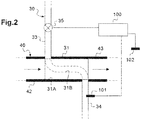
Comme le montrent la
Le refroidisseur EGR 31 comprend plus précisément une canalisation principale 31A au travers de laquelle circulent les gaz EGR, et une canalisation secondaire 31 B au travers de laquelle circule un liquide de refroidissement.The
La canalisation principale 31A est connectée, d'un côté, à la ligne d'échappement 80 via un conduit amont 42 de la ligne EGR-HP 40, et, de l'autre, à la vanne EGR-HP 41 via un conduit aval 43 de la ligne EGR-HP 40.The
La canalisation secondaire 31 B est quant à elle connectée au reste du circuit de refroidissement secondaire 30, d'un côté, par un conduit amont 33, et, de l'autre, par un conduit aval 34.The
Le circuit de refroidissement secondaire 30 comprend par ailleurs une vanne de régulation 35 du débit de liquide de refroidissement.The
Cette vanne de régulation 35 est ici agencée sur le conduit amont 33 du circuit de refroidissement secondaire 30. En variante, elle pourrait bien entendu être agencée ailleurs, par exemple sur le conduit aval.This
La vanne de régulation 35 est adaptée à être pilotée dans l'une ou l'autre d'au moins trois positions stables, dont :
- une position extrême de fermeture dans laquelle elle obture totalement le conduit amont 33, de sorte que le débit du liquide de refroidissement circulant dans le circuit de refroidissement
secondaire 30 est nul, - une position extrême d'ouverture dans laquelle elle libère totalement le conduit amont 33, de sorte que le débit du liquide de refroidissement circulant dans le circuit de refroidissement
secondaire 30 est maximal, et - au moins une position intermédiaire dans laquelle elle obture partiellement le conduit amont 33, de sorte que le débit du liquide de refroidissement circulant dans le circuit de refroidissement
secondaire 30 est non nul et est strictement inférieur au débit maximal.
- an extreme closing position in which it completely closes the
upstream duct 33, so that the flow rate of the cooling liquid circulating in thesecondary cooling circuit 30 is zero, - an extreme opening position in which it completely releases the
upstream duct 33, so that the flow rate of the coolant circulating in thesecondary cooling circuit 30 is maximum, and - at least one intermediate position in which it partially closes the
upstream duct 33, so that the flow rate of the cooling liquid flowing in thesecondary cooling circuit 30 is non-zero and is strictly less than the maximum flow rate.
La vanne de régulation 35 est ici un volet papillon, mais il pourrait bien entendu en être autrement.The
Classiquement, la circulation du liquide de refroidissement dans ce circuit de refroidissement secondaire 30 est assurée par une pompe de mise en pression (non représentée). Le liquide de refroidissement utilisé ici est un mélange d'eau et de glycol.Conventionally, the circulation of the coolant in this
Comme le montre la
Grâce à ses interfaces d'entrée, le calculateur 100 est adapté à recevoir de différents capteurs des signaux d'entrée relatifs au fonctionnement du moteur et aux conditions climatiques.Thanks to its input interfaces, the
Parmi ces capteurs, il est notamment prévu une première sonde de température 101 qui permet de mesurer la température To instantanée du liquide de refroidissement circulant dans le circuit de refroidissement secondaire 30.Among these sensors, a
Dans le mode de réalisation du moteur à combustion interne 1 représenté sur la
Dans ce mode de réalisation, la première sonde de température sera donc positionnée à distance du refroidisseur EGR 31, de préférence à 10cm de celui-ci, de manière à ce que les mesures ne soient pas perturbées par le refroidisseur EGR 31.In this embodiment, the first temperature probe will therefore be positioned at a distance from the
Selon une variante non représentée, on pourrait toutefois prévoir que la première sonde de température soit située à l'intérieur du refroidisseur EGR lui-même.According to a variant not shown, it could however be provided that the first temperature sensor is located inside the EGR cooler itself.
Grâce à ces sondes de température et à différents autres capteurs, le calculateur 100 mémorise ainsi en continu dans sa mémoire vive :
- la charge C instantanée du moteur à combustion interne 1,
- le régime R instantané du moteur à combustion interne 1,
- la température To du liquide de refroidissement,
- la température ambiante Ta (dans le premier mode de réalisation), et
- le débit de carburant injecté dans les cylindres 11.
- the instantaneous charge C of the internal combustion engine 1,
- the instantaneous R speed of the internal combustion engine 1,
- the temperature To of the coolant,
- the ambient temperature Ta (in the first embodiment), and
- the fuel flow injected into the
cylinders 11.
La charge C (également appelée « charge-moteur ») correspond au rapport du travail fourni par le moteur sur le travail maximal que pourrait développer ce moteur à un régime donné. Elle est généralement approximée à l'aide d'une variable appelée pression moyenne effective PME.The load C (also called "engine load") corresponds to the ratio of the work supplied by the engine to the maximum work that could develop this engine at a given speed. It is usually approximated using a variable called effective average pressure SME.
Le régime R correspond à la vitesse de rotation du vilebrequin, exprimée en tours par minute.The R speed corresponds to the speed of rotation of the crankshaft, expressed in revolutions per minute.
Grâce à une cartographie prédéterminée sur banc d'essais et mémorisée dans sa mémoire morte (ROM), le calculateur 100 est adapté à générer, pour chaque condition de fonctionnement du moteur, des signaux de sortie.Thanks to a predetermined mapping on test bench and stored in its read-only memory (ROM), the
Enfin, grâce à ses interfaces de sortie, le calculateur 100 est adapté à transmettre ces signaux de sortie aux différents organes du moteur, notamment à la vanne de régulation 35.Finally, thanks to its output interfaces, the
Classiquement, lorsque le conducteur du véhicule automobile met le contact, le calculateur 100 s'initialise puis commande le démarreur et les injecteurs de carburant 64 pour que ceux-ci démarrent le moteur à combustion interne 1.Conventionally, when the driver of the motor vehicle puts the ignition, the
Lorsque le moteur est démarré, l'air frais prélevé dans l'atmosphère par la ligne d'admission 20 est filtré par le filtre à air 21, comprimé par le compresseur 22, refroidi par le refroidisseur d'air principal 23, puis brûlé dans les cylindres 11.When the engine is started, the fresh air taken from the atmosphere through the
A leur sortie des cylindres 11, les gaz brûlés sont détendus dans la turbine 82, traités et filtrés dans le pot catalytique 83, puis détendus à nouveau dans le silencieux d'échappement 84 avant d'être rejetés dans l'atmosphère.At their outlet from the
Une partie de ces gaz brûlés est toutefois prélevée par la ligne EGR-HP 40 pour être réinjectée dans la ligne d'admission 20. Ces gaz EGR sont alors préalablement refroidis dans le refroidisseur EGR 31.Part of these flue gas is, however, taken by the line EGR-
Le calculateur 100 pilote à cet effet la vanne de régulation 35 du débit de liquide de refroidissement circulant dans le circuit de refroidissement secondaire 30, de manière que ces gaz EGR soient refroidis à la température souhaitée.The
Ainsi, par exemple, au démarrage du moteur, lorsque la température ambiante Ta est faible, cette vanne de régulation 35 est pilotée en position extrême de fermeture (le temps que la température des gaz EGR augmente) avant d'être progressivement ouverte.Thus, for example, when the engine starts, when the ambient temperature Ta is low, this
Selon une caractéristique particulièrement avantageuse de l'invention, le calculateur 100 est adapté à mettre en oeuvre un procédé de pilotage de la vanne de régulation 35 qui comprend les trois étapes suivantes :
- a) acquérir la température To du liquide de refroidissement,
- b) déterminer, en fonction de la température To acquise à l'étape a), une consigne de pilotage C1 de la vanne de régulation 35 dans l'une de ses positions stables, et
- c) piloter la vanne de régulation 35 selon cette consigne de pilotage C1.
- a) acquiring the temperature To of the coolant,
- b) determining, as a function of the temperature To, acquired in step a), a control setpoint C1 of the
control valve 35 in one of its stable positions, and - c) control the
control valve 35 according to this control setpoint C1.
Grâce à l'invention, le débit de liquide de refroidissement circulant dans le circuit de refroidissement secondaire 30 est régulé en fonction de la température To du liquide de refroidissement (et non en fonction de la température des gaz EGR), ce qui évite notamment tout risque d'ébullition ou de changement de température brusque du liquide de refroidissement, au bénéfice de la longévité du refroidisseur EGR 31.Thanks to the invention, the coolant flow circulating in the
On notera ici que plus le nombre de positions stables (dans lesquelles la vanne de régulation 35 pourra être piloté) sera grand, plus la régulation de la température des gaz EGR pourra être affinée, ce qui réduira en conséquence l'encrassement de la ligne EGR-HP 40, notamment lorsque la température ambiante Ta est faible.It will be noted here that the greater the number of stable positions (in which the
Ainsi, si le nombre minimal de positions stables est de trois, on prévoira de préférence que la vanne de régulation 35 puisse présenter au moins cinq positions stables. On pourra bien entendu prévoir qu'elle puisse présenter plus de 10 positions stables.Thus, if the minimum number of stable positions is three, it will preferably be provided that the
Dans l'exemple qui sera exposé dans la suite de cet exposé, la vanne de régulation 35 pourra prendre une infinité de positions stables.In the example which will be explained in the rest of this discussion, the
Lorsque le moteur à combustion interne 1 sera du type de celui représenté sur la
Plus précisément, après le démarrage du moteur à combustion interne (opération 71), l'initialisation du calculateur 100 et le début de la circulation du liquide de refroidissement dans le circuit de refroidissement secondaire 30 (opération 72), le calculateur 100 met en oeuvre l'algorithme suivant.More precisely, after the start of the internal combustion engine (operation 71), the initialization of the
Le calculateur 100 vérifie tout d'abord si un arrêt du moteur à combustion interne 1 est requis (opération 73).The
Si une commande d'arrêt du moteur à combustion interne 1 est détectée, le calculateur 100 pilote l'arrêt de la pompe de mise en pression du liquide de refroidissement (opération 74) puis l'arrêt de l'injection de carburant dans les cylindres 11 (opération 75).If a stop command of the internal combustion engine 1 is detected, the
Dans le cas contraire, le calculateur 100 acquiert la température To du liquide de refroidissement en aval du refroidisseur EGR 31 (opération 76) ainsi que la température ambiante Ta (opération 77).In the opposite case, the
Le calculateur 100 calcule alors une température cible Tc de liquide de refroidissement en fonction au moins de la température ambiante Ta mesurée (opération 78). Cette température cible Tc correspond à la température optimale du liquide de refroidissement, assurant un encrassement réduit de la ligne EGR-HP 40.The
Le calcul de cette température cible Tc est réalisé à l'aide d'une formule mathématique ou d'une cartographie mémorisée dans la mémoire morte (ROM) du calculateur 100 (cette cartographie faisant correspondre, à chaque température ambiante Ta, une température cible Tc).The calculation of this target temperature Tc is carried out using a mathematical formula or a map stored in the read-only memory (ROM) of the computer 100 (this map corresponding, at each ambient temperature Ta, a target temperature Tc ).
En variante, on pourrait utiliser des paramètres supplémentaires pour calculer cette température cible Tc, par exemple la charge C instantanée du moteur à combustion interne 1 et/ou le régime R instantané du moteur à combustion interne 1, et/ou le débit de carburant injecté dans les cylindres 11.As a variant, it would be possible to use additional parameters for calculating this target temperature Tc, for example the instantaneous load C of the internal combustion engine 1 and / or the instantaneous R speed of the internal combustion engine 1, and / or the injected fuel flow rate. in the
Le calculateur 100 compare ensuite la température To du liquide de refroidissement mesurée avec la température cible Tc calculée (opération 79).The
Si la température To du liquide de refroidissement est inférieure à la température cible Tc, alors la vanne de régulation 35 est pilotée à l'ouverture (opération 84), de manière à augmenter le débit de liquide de refroidissement circulant dans le refroidisseur EGR 31.If the temperature To of the coolant is lower than the target temperature Tc, then the
La consigne de pilotage C1 étant ici formée par l'angle d'ouverture que la vanne de régulation 35 doit prendre (C1 étant égal à zéro en position extrême de fermeture), cette consigne de pilotage C1 est calculée de la manière suivante (opération 83) : ![]()
- t est le temps,
- k est une constante prédéterminée enregistrée dans la mémoire morte (ROM) du calculateur 100,
- Δt est une différence de temps (en l'occurrence le pas de temps entre deux calculs successifs de la consigne de pilotage C1), et
- ΔC1 = C1 (t) - C1 (t - Δt).
- t is the time,
- k is a predetermined constant stored in the read only memory (ROM) of the
computer 100, - Δt is a time difference (in this case the time step between two successive calculations of the control setpoint C1), and
- ΔC1 = C1 (t) - C1 (t - Δt).
Au contraire, si la température To du liquide de refroidissement est supérieure ou égale à la température cible Tc, alors la vanne de régulation 35 est pilotée à la fermeture (opération 82), de manière à réduire le débit de liquide de refroidissement circulant dans le refroidisseur EGR 31.On the other hand, if the temperature To of the coolant is greater than or equal to the target temperature Tc, then the
La consigne de pilotage C1 est alors calculée de la manière suivante (opération 81) : ![]()
![]()
Cette consigne de pilotage C1 est ensuite transmise à la vanne de régulation 35, qui s'ouvre ou se ferme en conséquence (opérations 82 ou 84).This control setpoint C1 is then transmitted to the
Puis, le calculateur 100 revient au début de la boucle (opération 73).Then, the
La présente invention n'est nullement limitée au mode de réalisation décrit et représenté, mais l'homme du métier saura y apporter toute variante conforme à son esprit.The present invention is not limited to the embodiment described and shown, but the art can apply any variant within his mind.
On pourra par exemple prévoir de piloter la vanne de régulation du débit de liquide de refroidissement autrement, notamment lorsque la sonde de température sera située dans le refroidisseur EGR ou en aval du refroidisseur EGR.For example, it will be possible to control the valve for regulating the coolant flow otherwise, especially when the temperature probe is located in the EGR cooler or downstream of the EGR cooler.
Dans cette variante, on pourra prévoir d'évaluer, en fonction de la température mesurée et éventuellement d'autres paramètres (par exemple le débit et la température des gaz EGR), une température estimée du liquide de refroidissement en amont du refroidisseur EGR.In this variant, it will be possible to evaluate, as a function of the measured temperature and possibly other parameters (for example the flow rate and the temperature of the EGR gases), an estimated temperature of the coolant upstream of the EGR cooler.
Dans cette variante, le débit et la température des gaz EGR pourront être mesurés ou calculés en fonction du régime et du couple moteur.In this variant, the flow rate and the temperature of the EGR gases can be measured or calculated as a function of engine speed and torque.
Claims (8)
- Method for controlling a regulating valve (35) that regulates a flowrate of liquid coolant circulating in a cooling circuit (30) of a recirculation line (20) of an internal combustion engine (1), characterized in that it comprises steps consisting in:a) acquiring the temperature (To) of the said liquid coolant,b) determining, as a function of the temperature (To) acquired at step a), a control point (C1) for the said regulating valve (35) in a stable position chosen from at least three stable positions, andc) controlling the regulating valve (35) according to the control point (C1) determined in step b),characterized in that, in step b), the said control point (C1) is determined as a function of the acquired temperature (To) of the liquid coolant and of a liquid coolant target temperature (Tc) which is deduced from the ambient temperature (Ta) measured beforehand.
- Control method according to Claim 1, in which, with the cooling circuit comprising a heat exchanger positioned on the recirculation line, in step a) the temperature of the liquid coolant is measured inside the said heat exchanger.
- Control method according to Claim 1, in which, with the cooling circuit (30) comprising a heat exchanger (31) positioned on the recirculation line (20), in step a) the temperature (To) of the liquid coolant is measured some distance away from the said heat exchanger (31).
- Control method according to Claim 3, in which in step a) the temperature (To) of the liquid coolant is measured downstream of the said heat exchanger (31).
- Control method according to one of Claims 2 and 4, in which, in step b) a value for the temperature of the liquid coolant upstream of the said heat exchanger is estimated as a function of the measured liquid coolant temperature, of a flowrate of burnt gases in the said recirculation line, and of a temperature of burnt gases in the said recirculation line.
- Control method according to any one of Claims 1 to 5, in which the instantaneous load (C) on the internal combustion engine (1) and/or the instantaneous speed (R) of the internal combustion engine (1), and/or the flowrate of fuel injected into the cylinders (11) of the internal combustion engine (1) are used to calculate the target temperature (Tc).
- Cooling circuit (30) for cooling the burnt gases circulating in a recirculation line (20) of an internal combustion engine (1), comprising:- a heat exchanger (31) positioned on the said recirculation line (20),- two liquid-coolant circulation pipes (33, 34) connected respectively at the inlet and outlet of the said heat exchanger (31), and- a regulating valve (35) for regulating a flowrate of liquid coolant, which valve is arranged on one of the said circulation pipes (33, 34), characterized in that it comprises a control unit (40) for controlling the said regulating valve (35), which is able to implement a control method according to one of Claims 1 to 6.
- Internal combustion engine (1) comprising:- an engine block which internally defines cylinders,- an intake line admitting intake gas into the said cylinders,- an exhaust line exhausting burnt gases from the said cylinders,- an exhaust gas recirculation line (20) which starts in the said exhaust line and which opens into the said intake line, characterized in that it comprises a cooling circuit (30) according to Claim 7.
Applications Claiming Priority (2)
| Application Number | Priority Date | Filing Date | Title |
|---|---|---|---|
| FR1351334A FR3002276B1 (en) | 2013-02-15 | 2013-02-15 | METHOD FOR CONTROLLING A RECIRCULATING GAS FLOW CONTROL VALVE OF AN INTERNAL COMBUSTION ENGINE |
| PCT/FR2014/050117 WO2014125181A1 (en) | 2013-02-15 | 2014-01-22 | Method for controlling a control valve for controlling the flow rate of a coolant for cooling the recirculated gases of an internal combustion engine |
Publications (2)
| Publication Number | Publication Date |
|---|---|
| EP2956656A1 EP2956656A1 (en) | 2015-12-23 |
| EP2956656B1 true EP2956656B1 (en) | 2017-03-22 |
Family
ID=48521192
Family Applications (1)
| Application Number | Title | Priority Date | Filing Date |
|---|---|---|---|
| EP14705834.1A Active EP2956656B1 (en) | 2013-02-15 | 2014-01-22 | Method for controlling a control valve for controlling the flow rate of a coolant for cooling the recirculated gases of an internal combustion engine |
Country Status (3)
| Country | Link |
|---|---|
| EP (1) | EP2956656B1 (en) |
| FR (1) | FR3002276B1 (en) |
| WO (1) | WO2014125181A1 (en) |
Family Cites Families (3)
| Publication number | Priority date | Publication date | Assignee | Title |
|---|---|---|---|---|
| JPS55131557A (en) * | 1979-04-02 | 1980-10-13 | Toyota Motor Corp | Egr gas temperature controller |
| US8056544B2 (en) * | 2008-08-27 | 2011-11-15 | Ford Global Technologies, Llc | Exhaust gas recirculation (EGR) system |
| KR101251526B1 (en) * | 2011-06-13 | 2013-04-05 | 기아자동차주식회사 | Low pressure egr system and examining method for efficeincy of low egr cooler |
-
2013
- 2013-02-15 FR FR1351334A patent/FR3002276B1/en not_active Expired - Fee Related
-
2014
- 2014-01-22 EP EP14705834.1A patent/EP2956656B1/en active Active
- 2014-01-22 WO PCT/FR2014/050117 patent/WO2014125181A1/en active Application Filing
Non-Patent Citations (1)
| Title |
|---|
| None * |
Also Published As
| Publication number | Publication date |
|---|---|
| FR3002276B1 (en) | 2016-05-27 |
| WO2014125181A1 (en) | 2014-08-21 |
| FR3002276A1 (en) | 2014-08-22 |
| EP2956656A1 (en) | 2015-12-23 |
Similar Documents
| Publication | Publication Date | Title |
|---|---|---|
| WO2007148007A1 (en) | Exhaust gas recirculation system for a combustion engine of the supercharged diesel type and method for controlling such an engine | |
| EP2853723A1 (en) | Method for determining the EGR rate in a heat engine | |
| EP2699778B1 (en) | Fault diagnosis method of supercharged motor and supercharged motor | |
| EP2956656B1 (en) | Method for controlling a control valve for controlling the flow rate of a coolant for cooling the recirculated gases of an internal combustion engine | |
| FR2921432A1 (en) | Assembly i.e. exhaust gas recirculation device, function diagnosing method, involves comparing calculated difference with predetermined threshold value, diagnosing function of assembly based on comparison result | |
| WO2010026340A1 (en) | Method for determining the soot load of a particle filter | |
| FR2910059A1 (en) | Exhaust gas pressure estimating method for oil engine of motor vehicle, involves estimating pressure of exhaust gas in upstream of turbine by choosing one of two formulas comprising parameters e.g. pressure of gas in downstream of turbine | |
| FR2923544A1 (en) | Supercharged diesel internal combustion engine for motor vehicle, has control unit with calculating unit that calculates setpoint position values of valve and flaps from setpoint values of air flow and gas rates in engine | |
| EP2844858B1 (en) | Method of exhaust gas aftertreatment of a supercharged combustion engine with exhaust gas recirculation | |
| FR2923538A3 (en) | Turbine upstream pressure estimating system for supercharged oil engine of motor vehicle, has calculation units calculating expansion ratio of turbine from magnitude representing temperature variation to deduce upstream pressure of turbine | |
| EP2262997A1 (en) | System and method for diagnosing the operational condition of an exhaust gas inlet device for automobile internal combustion engine | |
| FR2927368A1 (en) | Fresh intake air flow rate estimating device for e.g. oil engine of motor vehicle, has electronic control unit for estimating fresh intake air flow rate from measured temperature and pressure | |
| FR2923537A1 (en) | Pressure estimation system for diesel engine of motor vehicle, has calculation unit calculating pressure drop ratio of turbine from magnitude representing variation relative to temperature between inlet and outlet of turbine | |
| EP3353405B1 (en) | Device for cooling an exhaust gas recirculation loop of a motor vehicle engine | |
| FR3059719B1 (en) | METHOD FOR CONTROLLING A SUPERIOR THERMAL MOTOR COMPRISING AN EXHAUST GAS RECIRCULATION CIRCUIT | |
| FR3058471A1 (en) | METHOD FOR CONTROLLING A SUPERIOR THERMAL MOTOR COMPRISING AN EXHAUST GAS RECIRCULATION LINE | |
| FR2975134A1 (en) | ESTIMATING THE EGR GAS RATE IN A VEHICLE HEAT ENGINE | |
| EP2066892B1 (en) | Control system for a motor vehicle internal combustion engine that comprises an engine exhaust gas recirculation circuit provided with a controlled recirculation valve | |
| FR3028565A1 (en) | METHOD FOR DIAGNOSING THE INHIBITION OF AN AIR FILTER EQUIPPED WITH A SUPERIOR INTERNAL COMBUSTION ENGINE | |
| FR2858020A1 (en) | Internal combustion engine controlling process for vehicle, involves regulating airflow in exchanger and bypass, such that temperature of air in collector approaches predetermined value | |
| FR3048455A1 (en) | METHOD FOR DIAGNOSING AN EGR VALVE | |
| EP2354500A1 (en) | Method of driving a bypass valve of a turbine in an engine | |
| FR3069022A1 (en) | METHOD FOR CONTROLLING A SUPERIOR INTERNAL COMBUSTION ENGINE. | |
| FR3102216A1 (en) | PROCESS FOR CHECKING THE AIR SUPPLY OF A COMBUSTION ENGINE | |
| FR3076577A1 (en) | METHOD OF ESTIMATING RECIRCULATED EXHAUST GAS FLOW IN AN INTAKE MANIFOLD OF A HEAT ENGINE |
Legal Events
| Date | Code | Title | Description |
|---|---|---|---|
| PUAI | Public reference made under article 153(3) epc to a published international application that has entered the european phase |
Free format text: ORIGINAL CODE: 0009012 |
|
| 17P | Request for examination filed |
Effective date: 20150630 |
|
| AK | Designated contracting states |
Kind code of ref document: A1 Designated state(s): AL AT BE BG CH CY CZ DE DK EE ES FI FR GB GR HR HU IE IS IT LI LT LU LV MC MK MT NL NO PL PT RO RS SE SI SK SM TR |
|
| AX | Request for extension of the european patent |
Extension state: BA ME |
|
| DAX | Request for extension of the european patent (deleted) | ||
| 17Q | First examination report despatched |
Effective date: 20160610 |
|
| REG | Reference to a national code |
Ref country code: DE Ref legal event code: R079 Ref document number: 602014007833 Country of ref document: DE Free format text: PREVIOUS MAIN CLASS: F02M0025070000 Ipc: F02M0026280000 |
|
| GRAP | Despatch of communication of intention to grant a patent |
Free format text: ORIGINAL CODE: EPIDOSNIGR1 |
|
| STAA | Information on the status of an ep patent application or granted ep patent |
Free format text: STATUS: GRANT OF PATENT IS INTENDED |
|
| RIC1 | Information provided on ipc code assigned before grant |
Ipc: F01P 3/12 20060101ALI20161010BHEP Ipc: F02M 26/28 20160101AFI20161010BHEP |
|
| INTG | Intention to grant announced |
Effective date: 20161110 |
|
| GRAS | Grant fee paid |
Free format text: ORIGINAL CODE: EPIDOSNIGR3 |
|
| GRAA | (expected) grant |
Free format text: ORIGINAL CODE: 0009210 |
|
| STAA | Information on the status of an ep patent application or granted ep patent |
Free format text: STATUS: THE PATENT HAS BEEN GRANTED |
|
| AK | Designated contracting states |
Kind code of ref document: B1 Designated state(s): AL AT BE BG CH CY CZ DE DK EE ES FI FR GB GR HR HU IE IS IT LI LT LU LV MC MK MT NL NO PL PT RO RS SE SI SK SM TR |
|
| REG | Reference to a national code |
Ref country code: GB Ref legal event code: FG4D Free format text: NOT ENGLISH |
|
| REG | Reference to a national code |
Ref country code: CH Ref legal event code: EP |
|
| REG | Reference to a national code |
Ref country code: AT Ref legal event code: REF Ref document number: 878049 Country of ref document: AT Kind code of ref document: T Effective date: 20170415 |
|
| REG | Reference to a national code |
Ref country code: IE Ref legal event code: FG4D Free format text: LANGUAGE OF EP DOCUMENT: FRENCH |
|
| REG | Reference to a national code |
Ref country code: DE Ref legal event code: R096 Ref document number: 602014007833 Country of ref document: DE |
|
| REG | Reference to a national code |
Ref country code: NL Ref legal event code: MP Effective date: 20170322 |
|
| PG25 | Lapsed in a contracting state [announced via postgrant information from national office to epo] |
Ref country code: LT Free format text: LAPSE BECAUSE OF FAILURE TO SUBMIT A TRANSLATION OF THE DESCRIPTION OR TO PAY THE FEE WITHIN THE PRESCRIBED TIME-LIMIT Effective date: 20170322 Ref country code: HR Free format text: LAPSE BECAUSE OF FAILURE TO SUBMIT A TRANSLATION OF THE DESCRIPTION OR TO PAY THE FEE WITHIN THE PRESCRIBED TIME-LIMIT Effective date: 20170322 Ref country code: FI Free format text: LAPSE BECAUSE OF FAILURE TO SUBMIT A TRANSLATION OF THE DESCRIPTION OR TO PAY THE FEE WITHIN THE PRESCRIBED TIME-LIMIT Effective date: 20170322 Ref country code: NO Free format text: LAPSE BECAUSE OF FAILURE TO SUBMIT A TRANSLATION OF THE DESCRIPTION OR TO PAY THE FEE WITHIN THE PRESCRIBED TIME-LIMIT Effective date: 20170622 Ref country code: GR Free format text: LAPSE BECAUSE OF FAILURE TO SUBMIT A TRANSLATION OF THE DESCRIPTION OR TO PAY THE FEE WITHIN THE PRESCRIBED TIME-LIMIT Effective date: 20170623 |
|
| REG | Reference to a national code |
Ref country code: LT Ref legal event code: MG4D |
|
| REG | Reference to a national code |
Ref country code: AT Ref legal event code: MK05 Ref document number: 878049 Country of ref document: AT Kind code of ref document: T Effective date: 20170322 |
|
| PG25 | Lapsed in a contracting state [announced via postgrant information from national office to epo] |
Ref country code: LV Free format text: LAPSE BECAUSE OF FAILURE TO SUBMIT A TRANSLATION OF THE DESCRIPTION OR TO PAY THE FEE WITHIN THE PRESCRIBED TIME-LIMIT Effective date: 20170322 Ref country code: BG Free format text: LAPSE BECAUSE OF FAILURE TO SUBMIT A TRANSLATION OF THE DESCRIPTION OR TO PAY THE FEE WITHIN THE PRESCRIBED TIME-LIMIT Effective date: 20170622 Ref country code: SE Free format text: LAPSE BECAUSE OF FAILURE TO SUBMIT A TRANSLATION OF THE DESCRIPTION OR TO PAY THE FEE WITHIN THE PRESCRIBED TIME-LIMIT Effective date: 20170322 Ref country code: RS Free format text: LAPSE BECAUSE OF FAILURE TO SUBMIT A TRANSLATION OF THE DESCRIPTION OR TO PAY THE FEE WITHIN THE PRESCRIBED TIME-LIMIT Effective date: 20170322 |
|
| PG25 | Lapsed in a contracting state [announced via postgrant information from national office to epo] |
Ref country code: NL Free format text: LAPSE BECAUSE OF FAILURE TO SUBMIT A TRANSLATION OF THE DESCRIPTION OR TO PAY THE FEE WITHIN THE PRESCRIBED TIME-LIMIT Effective date: 20170322 |
|
| PG25 | Lapsed in a contracting state [announced via postgrant information from national office to epo] |
Ref country code: RO Free format text: LAPSE BECAUSE OF FAILURE TO SUBMIT A TRANSLATION OF THE DESCRIPTION OR TO PAY THE FEE WITHIN THE PRESCRIBED TIME-LIMIT Effective date: 20170322 Ref country code: SK Free format text: LAPSE BECAUSE OF FAILURE TO SUBMIT A TRANSLATION OF THE DESCRIPTION OR TO PAY THE FEE WITHIN THE PRESCRIBED TIME-LIMIT Effective date: 20170322 Ref country code: ES Free format text: LAPSE BECAUSE OF FAILURE TO SUBMIT A TRANSLATION OF THE DESCRIPTION OR TO PAY THE FEE WITHIN THE PRESCRIBED TIME-LIMIT Effective date: 20170322 Ref country code: EE Free format text: LAPSE BECAUSE OF FAILURE TO SUBMIT A TRANSLATION OF THE DESCRIPTION OR TO PAY THE FEE WITHIN THE PRESCRIBED TIME-LIMIT Effective date: 20170322 Ref country code: AT Free format text: LAPSE BECAUSE OF FAILURE TO SUBMIT A TRANSLATION OF THE DESCRIPTION OR TO PAY THE FEE WITHIN THE PRESCRIBED TIME-LIMIT Effective date: 20170322 Ref country code: CZ Free format text: LAPSE BECAUSE OF FAILURE TO SUBMIT A TRANSLATION OF THE DESCRIPTION OR TO PAY THE FEE WITHIN THE PRESCRIBED TIME-LIMIT Effective date: 20170322 |
|
| PG25 | Lapsed in a contracting state [announced via postgrant information from national office to epo] |
Ref country code: PT Free format text: LAPSE BECAUSE OF FAILURE TO SUBMIT A TRANSLATION OF THE DESCRIPTION OR TO PAY THE FEE WITHIN THE PRESCRIBED TIME-LIMIT Effective date: 20170724 Ref country code: SM Free format text: LAPSE BECAUSE OF FAILURE TO SUBMIT A TRANSLATION OF THE DESCRIPTION OR TO PAY THE FEE WITHIN THE PRESCRIBED TIME-LIMIT Effective date: 20170322 Ref country code: IS Free format text: LAPSE BECAUSE OF FAILURE TO SUBMIT A TRANSLATION OF THE DESCRIPTION OR TO PAY THE FEE WITHIN THE PRESCRIBED TIME-LIMIT Effective date: 20170722 Ref country code: PL Free format text: LAPSE BECAUSE OF FAILURE TO SUBMIT A TRANSLATION OF THE DESCRIPTION OR TO PAY THE FEE WITHIN THE PRESCRIBED TIME-LIMIT Effective date: 20170322 |
|
| REG | Reference to a national code |
Ref country code: DE Ref legal event code: R097 Ref document number: 602014007833 Country of ref document: DE |
|
| REG | Reference to a national code |
Ref country code: FR Ref legal event code: PLFP Year of fee payment: 5 |
|
| PLBE | No opposition filed within time limit |
Free format text: ORIGINAL CODE: 0009261 |
|
| STAA | Information on the status of an ep patent application or granted ep patent |
Free format text: STATUS: NO OPPOSITION FILED WITHIN TIME LIMIT |
|
| PG25 | Lapsed in a contracting state [announced via postgrant information from national office to epo] |
Ref country code: DK Free format text: LAPSE BECAUSE OF FAILURE TO SUBMIT A TRANSLATION OF THE DESCRIPTION OR TO PAY THE FEE WITHIN THE PRESCRIBED TIME-LIMIT Effective date: 20170322 |
|
| 26N | No opposition filed |
Effective date: 20180102 |
|
| PG25 | Lapsed in a contracting state [announced via postgrant information from national office to epo] |
Ref country code: SI Free format text: LAPSE BECAUSE OF FAILURE TO SUBMIT A TRANSLATION OF THE DESCRIPTION OR TO PAY THE FEE WITHIN THE PRESCRIBED TIME-LIMIT Effective date: 20170322 Ref country code: IT Free format text: LAPSE BECAUSE OF FAILURE TO SUBMIT A TRANSLATION OF THE DESCRIPTION OR TO PAY THE FEE WITHIN THE PRESCRIBED TIME-LIMIT Effective date: 20170322 |
|
| REG | Reference to a national code |
Ref country code: CH Ref legal event code: PL |
|
| PG25 | Lapsed in a contracting state [announced via postgrant information from national office to epo] |
Ref country code: MT Free format text: LAPSE BECAUSE OF FAILURE TO SUBMIT A TRANSLATION OF THE DESCRIPTION OR TO PAY THE FEE WITHIN THE PRESCRIBED TIME-LIMIT Effective date: 20170322 |
|
| PG25 | Lapsed in a contracting state [announced via postgrant information from national office to epo] |
Ref country code: LU Free format text: LAPSE BECAUSE OF NON-PAYMENT OF DUE FEES Effective date: 20180122 |
|
| REG | Reference to a national code |
Ref country code: IE Ref legal event code: MM4A |
|
| REG | Reference to a national code |
Ref country code: BE Ref legal event code: MM Effective date: 20180131 |
|
| PG25 | Lapsed in a contracting state [announced via postgrant information from national office to epo] |
Ref country code: LI Free format text: LAPSE BECAUSE OF NON-PAYMENT OF DUE FEES Effective date: 20180131 Ref country code: BE Free format text: LAPSE BECAUSE OF NON-PAYMENT OF DUE FEES Effective date: 20180131 Ref country code: CH Free format text: LAPSE BECAUSE OF NON-PAYMENT OF DUE FEES Effective date: 20180131 |
|
| PG25 | Lapsed in a contracting state [announced via postgrant information from national office to epo] |
Ref country code: IE Free format text: LAPSE BECAUSE OF NON-PAYMENT OF DUE FEES Effective date: 20180122 |
|
| PG25 | Lapsed in a contracting state [announced via postgrant information from national office to epo] |
Ref country code: MC Free format text: LAPSE BECAUSE OF FAILURE TO SUBMIT A TRANSLATION OF THE DESCRIPTION OR TO PAY THE FEE WITHIN THE PRESCRIBED TIME-LIMIT Effective date: 20170322 |
|
| PG25 | Lapsed in a contracting state [announced via postgrant information from national office to epo] |
Ref country code: TR Free format text: LAPSE BECAUSE OF FAILURE TO SUBMIT A TRANSLATION OF THE DESCRIPTION OR TO PAY THE FEE WITHIN THE PRESCRIBED TIME-LIMIT Effective date: 20170322 |
|
| PG25 | Lapsed in a contracting state [announced via postgrant information from national office to epo] |
Ref country code: HU Free format text: LAPSE BECAUSE OF FAILURE TO SUBMIT A TRANSLATION OF THE DESCRIPTION OR TO PAY THE FEE WITHIN THE PRESCRIBED TIME-LIMIT; INVALID AB INITIO Effective date: 20140122 Ref country code: CY Free format text: LAPSE BECAUSE OF FAILURE TO SUBMIT A TRANSLATION OF THE DESCRIPTION OR TO PAY THE FEE WITHIN THE PRESCRIBED TIME-LIMIT Effective date: 20170322 Ref country code: MK Free format text: LAPSE BECAUSE OF NON-PAYMENT OF DUE FEES Effective date: 20170322 |
|
| PG25 | Lapsed in a contracting state [announced via postgrant information from national office to epo] |
Ref country code: AL Free format text: LAPSE BECAUSE OF FAILURE TO SUBMIT A TRANSLATION OF THE DESCRIPTION OR TO PAY THE FEE WITHIN THE PRESCRIBED TIME-LIMIT Effective date: 20170322 |
|
| PGFP | Annual fee paid to national office [announced via postgrant information from national office to epo] |
Ref country code: FR Payment date: 20230124 Year of fee payment: 10 |
|
| PGFP | Annual fee paid to national office [announced via postgrant information from national office to epo] |
Ref country code: GB Payment date: 20230119 Year of fee payment: 10 Ref country code: DE Payment date: 20230123 Year of fee payment: 10 |
|
| P01 | Opt-out of the competence of the unified patent court (upc) registered |
Effective date: 20230608 |
|
| REG | Reference to a national code |
Ref country code: GB Ref legal event code: 732E Free format text: REGISTERED BETWEEN 20231228 AND 20240103 |
|
| PGFP | Annual fee paid to national office [announced via postgrant information from national office to epo] |
Ref country code: DE Payment date: 20240119 Year of fee payment: 11 Ref country code: GB Payment date: 20240123 Year of fee payment: 11 |