EP2955738A1 - Connection member - Google Patents
Connection member Download PDFInfo
- Publication number
- EP2955738A1 EP2955738A1 EP14748635.1A EP14748635A EP2955738A1 EP 2955738 A1 EP2955738 A1 EP 2955738A1 EP 14748635 A EP14748635 A EP 14748635A EP 2955738 A1 EP2955738 A1 EP 2955738A1
- Authority
- EP
- European Patent Office
- Prior art keywords
- extension portion
- bent
- punching
- connection member
- extending
- Prior art date
- Legal status (The legal status is an assumption and is not a legal conclusion. Google has not performed a legal analysis and makes no representation as to the accuracy of the status listed.)
- Granted
Links
Images



Classifications
-
- H—ELECTRICITY
- H01—ELECTRIC ELEMENTS
- H01G—CAPACITORS; CAPACITORS, RECTIFIERS, DETECTORS, SWITCHING DEVICES, LIGHT-SENSITIVE OR TEMPERATURE-SENSITIVE DEVICES OF THE ELECTROLYTIC TYPE
- H01G11/00—Hybrid capacitors, i.e. capacitors having different positive and negative electrodes; Electric double-layer [EDL] capacitors; Processes for the manufacture thereof or of parts thereof
- H01G11/10—Multiple hybrid or EDL capacitors, e.g. arrays or modules
-
- H—ELECTRICITY
- H01—ELECTRIC ELEMENTS
- H01G—CAPACITORS; CAPACITORS, RECTIFIERS, DETECTORS, SWITCHING DEVICES, LIGHT-SENSITIVE OR TEMPERATURE-SENSITIVE DEVICES OF THE ELECTROLYTIC TYPE
- H01G2/00—Details of capacitors not covered by a single one of groups H01G4/00-H01G11/00
- H01G2/02—Mountings
- H01G2/04—Mountings specially adapted for mounting on a chassis
-
- H—ELECTRICITY
- H01—ELECTRIC ELEMENTS
- H01G—CAPACITORS; CAPACITORS, RECTIFIERS, DETECTORS, SWITCHING DEVICES, LIGHT-SENSITIVE OR TEMPERATURE-SENSITIVE DEVICES OF THE ELECTROLYTIC TYPE
- H01G11/00—Hybrid capacitors, i.e. capacitors having different positive and negative electrodes; Electric double-layer [EDL] capacitors; Processes for the manufacture thereof or of parts thereof
- H01G11/74—Terminals, e.g. extensions of current collectors
- H01G11/76—Terminals, e.g. extensions of current collectors specially adapted for integration in multiple or stacked hybrid or EDL capacitors
-
- H—ELECTRICITY
- H01—ELECTRIC ELEMENTS
- H01G—CAPACITORS; CAPACITORS, RECTIFIERS, DETECTORS, SWITCHING DEVICES, LIGHT-SENSITIVE OR TEMPERATURE-SENSITIVE DEVICES OF THE ELECTROLYTIC TYPE
- H01G11/00—Hybrid capacitors, i.e. capacitors having different positive and negative electrodes; Electric double-layer [EDL] capacitors; Processes for the manufacture thereof or of parts thereof
- H01G11/78—Cases; Housings; Encapsulations; Mountings
- H01G11/82—Fixing or assembling a capacitive element in a housing, e.g. mounting electrodes, current collectors or terminals in containers or encapsulations
-
- H—ELECTRICITY
- H01—ELECTRIC ELEMENTS
- H01H—ELECTRIC SWITCHES; RELAYS; SELECTORS; EMERGENCY PROTECTIVE DEVICES
- H01H37/00—Thermally-actuated switches
- H01H37/02—Details
- H01H37/32—Thermally-sensitive members
-
- H—ELECTRICITY
- H01—ELECTRIC ELEMENTS
- H01H—ELECTRIC SWITCHES; RELAYS; SELECTORS; EMERGENCY PROTECTIVE DEVICES
- H01H37/00—Thermally-actuated switches
- H01H37/74—Switches in which only the opening movement or only the closing movement of a contact is effected by heating or cooling
- H01H37/76—Contact member actuated by melting of fusible material, actuated due to burning of combustible material or due to explosion of explosive material
- H01H37/761—Contact member actuated by melting of fusible material, actuated due to burning of combustible material or due to explosion of explosive material with a fusible element forming part of the switched circuit
-
- H—ELECTRICITY
- H01—ELECTRIC ELEMENTS
- H01H—ELECTRIC SWITCHES; RELAYS; SELECTORS; EMERGENCY PROTECTIVE DEVICES
- H01H85/00—Protective devices in which the current flows through a part of fusible material and this current is interrupted by displacement of the fusible material when this current becomes excessive
- H01H85/02—Details
- H01H85/04—Fuses, i.e. expendable parts of the protective device, e.g. cartridges
- H01H85/05—Component parts thereof
- H01H85/055—Fusible members
- H01H85/08—Fusible members characterised by the shape or form of the fusible member
-
- H—ELECTRICITY
- H01—ELECTRIC ELEMENTS
- H01M—PROCESSES OR MEANS, e.g. BATTERIES, FOR THE DIRECT CONVERSION OF CHEMICAL ENERGY INTO ELECTRICAL ENERGY
- H01M50/00—Constructional details or processes of manufacture of the non-active parts of electrochemical cells other than fuel cells, e.g. hybrid cells
- H01M50/50—Current conducting connections for cells or batteries
- H01M50/502—Interconnectors for connecting terminals of adjacent batteries; Interconnectors for connecting cells outside a battery casing
- H01M50/503—Interconnectors for connecting terminals of adjacent batteries; Interconnectors for connecting cells outside a battery casing characterised by the shape of the interconnectors
-
- H—ELECTRICITY
- H01—ELECTRIC ELEMENTS
- H01M—PROCESSES OR MEANS, e.g. BATTERIES, FOR THE DIRECT CONVERSION OF CHEMICAL ENERGY INTO ELECTRICAL ENERGY
- H01M50/00—Constructional details or processes of manufacture of the non-active parts of electrochemical cells other than fuel cells, e.g. hybrid cells
- H01M50/50—Current conducting connections for cells or batteries
- H01M50/502—Interconnectors for connecting terminals of adjacent batteries; Interconnectors for connecting cells outside a battery casing
- H01M50/509—Interconnectors for connecting terminals of adjacent batteries; Interconnectors for connecting cells outside a battery casing characterised by the type of connection, e.g. mixed connections
- H01M50/512—Connection only in parallel
-
- H—ELECTRICITY
- H01—ELECTRIC ELEMENTS
- H01M—PROCESSES OR MEANS, e.g. BATTERIES, FOR THE DIRECT CONVERSION OF CHEMICAL ENERGY INTO ELECTRICAL ENERGY
- H01M50/00—Constructional details or processes of manufacture of the non-active parts of electrochemical cells other than fuel cells, e.g. hybrid cells
- H01M50/50—Current conducting connections for cells or batteries
- H01M50/572—Means for preventing undesired use or discharge
- H01M50/574—Devices or arrangements for the interruption of current
- H01M50/583—Devices or arrangements for the interruption of current in response to current, e.g. fuses
-
- H—ELECTRICITY
- H01—ELECTRIC ELEMENTS
- H01H—ELECTRIC SWITCHES; RELAYS; SELECTORS; EMERGENCY PROTECTIVE DEVICES
- H01H85/00—Protective devices in which the current flows through a part of fusible material and this current is interrupted by displacement of the fusible material when this current becomes excessive
- H01H85/02—Details
- H01H85/20—Bases for supporting the fuse; Separate parts thereof
- H01H85/205—Electric connections to contacts on the base
- H01H2085/2055—Connections to bus bars in an installation with screw in type fuses or knife blade fuses
-
- H—ELECTRICITY
- H01—ELECTRIC ELEMENTS
- H01M—PROCESSES OR MEANS, e.g. BATTERIES, FOR THE DIRECT CONVERSION OF CHEMICAL ENERGY INTO ELECTRICAL ENERGY
- H01M2200/00—Safety devices for primary or secondary batteries
- H01M2200/10—Temperature sensitive devices
- H01M2200/108—Normal resistors
-
- Y—GENERAL TAGGING OF NEW TECHNOLOGICAL DEVELOPMENTS; GENERAL TAGGING OF CROSS-SECTIONAL TECHNOLOGIES SPANNING OVER SEVERAL SECTIONS OF THE IPC; TECHNICAL SUBJECTS COVERED BY FORMER USPC CROSS-REFERENCE ART COLLECTIONS [XRACs] AND DIGESTS
- Y02—TECHNOLOGIES OR APPLICATIONS FOR MITIGATION OR ADAPTATION AGAINST CLIMATE CHANGE
- Y02E—REDUCTION OF GREENHOUSE GAS [GHG] EMISSIONS, RELATED TO ENERGY GENERATION, TRANSMISSION OR DISTRIBUTION
- Y02E60/00—Enabling technologies; Technologies with a potential or indirect contribution to GHG emissions mitigation
- Y02E60/10—Energy storage using batteries
-
- Y—GENERAL TAGGING OF NEW TECHNOLOGICAL DEVELOPMENTS; GENERAL TAGGING OF CROSS-SECTIONAL TECHNOLOGIES SPANNING OVER SEVERAL SECTIONS OF THE IPC; TECHNICAL SUBJECTS COVERED BY FORMER USPC CROSS-REFERENCE ART COLLECTIONS [XRACs] AND DIGESTS
- Y02—TECHNOLOGIES OR APPLICATIONS FOR MITIGATION OR ADAPTATION AGAINST CLIMATE CHANGE
- Y02E—REDUCTION OF GREENHOUSE GAS [GHG] EMISSIONS, RELATED TO ENERGY GENERATION, TRANSMISSION OR DISTRIBUTION
- Y02E60/00—Enabling technologies; Technologies with a potential or indirect contribution to GHG emissions mitigation
- Y02E60/13—Energy storage using capacitors
Definitions
- the present invention relates to a power storage device in which a plurality of storage elements is electrically connected to each other. More particularly, the present invention relates to a bus bar (a connection member) connected to a positive electrode or a negative electrode of each of the storage elements.
- a positive bus bar for connecting positive electrodes of a plurality of cylindrical batteries and a negative bus bar for connecting negative electrodes thereof are provided.
- the positive and negative electrodes of the cylindrical batteries are connected to respective bus bars via a fuse (a current limiter).
- a lead wire is used as the fuse, and when a current of a predetermined value or more such as an excess current flows, fusing is caused due to heat generation, so that electric connection between the bus bar and the positive electrode of the cylindrical battery and/or electric connection between the bus bar and the negative electrode of the cylindrical battery are/is cut off.
- Patent Document 1 International Publication No. 2008/121224
- Patent Document 1 different fuses are used for the battery and for the bus bar, so that it is necessary to connect the bus bar with the fuse and the cylindrical battery with the fuse, individually. Since the fuse and the bus bar are provided separately, there is such a problem that it is hard to secure a contact point that allows assembly tolerance, vibration displacement, and the like between the bus bar and the cylindrical battery.
- an object of the present invention is to provide a connection member configured to electrically connect respective storage elements to each other in a power storage device constituted by a plurality of storage elements, which connection member has a fusing characteristic as a fuse and is able to efficiently absorb/disperse stresses relative to displacements in three-dimensional directions between the storage elements and the connection member due to vibration or the like.
- a connection member configured to electrically connect respective storage elements to each other in a power storage device constituted by a plurality of storage elements.
- the connection member includes: a substrate; and a plurality of connecting portions connected to electrodes of the respective storage elements and configured to cut off electric connection with the storage elements by fusing at the time when a current of a predetermined value or more flows therein.
- the connecting portion is formed by performing punching on the substrate and includes at least two bent portions bent in a punching direction. Further, one of the bent portions is bent along a first direction perpendicular to the punching direction, and the other one of the bent portions is bent along a second direction perpendicular to the punching direction and perpendicular to the first direction.
- the connecting portion formed integrally with the substrate includes at least two bent portions bent in the punching direction. Further, the at least two bent portions are bent along the first direction and the second direction perpendicular to the punching direction and perpendicular to each other. On this account, stresses to act in respective directions perpendicular to the punching direction are absorbed/dispersed by bending displacements of respective bent portions bent in a thickness direction, and a stress to act in the punching direction is absorbed/dispersed by a displacement of the whole connection member in the thickness direction.
- connection member has a fusing characteristic as a current limiter (a fuse), and can efficiently absorb/disperse stresses relative to those displacements in three-dimensional directions between the storage element and the connection member which are caused due to vibration or the like.
- the connecting portion can be configured to include a first extension portion extending in the first direction, and a second extension portion extending from the first extension portion in the second direction.
- the at least two bent portions can be formed by bending the first extension portion and the second extension portion in the punching direction along their respective extending directions.
- the connecting portion can be configured to further include a third extension portion extending from the second extension portion in the first direction in a direction reverse to the extending direction of the first extension portion.
- the connecting portion can include a first extension portion extending generally in parallel with a direction perpendicular to the punching direction, a second extension portion bent from the first extension portion and extending generally in parallel with the direction perpendicular to the punching direction, and a third extension portion bent from the second extension portion and extending generally in parallel with the direction perpendicular to the punching direction.
- one of the bent portions can be formed such that a part bending between the first extension portion and the second extension portion is bent from a surface perpendicular to the punching direction along the first direction so as to become generally parallel with the punching direction.
- the other one of the bent portions can be formed such that a part bending between the second extension portion and the third extension portion is bent from the surface perpendicular to the punching direction along the second direction so as to become generally parallel with the punching direction.
- the third extension portion can be formed so as to extend from the second extension portion in a direction reverse to the extending direction of the first extension portion.
- Respective bending directions of the at least two bent portions can be configured to be the same or different from each other in the punching direction.
- the storage element can be configured as a cylindrical storage element having a longitudinal direction.
- the plurality of storage elements is arranged in line so that positive electrodes or negative electrodes placed in longitudinal-direction end parts thereof are oriented in the same direction.
- the connection member can be configured to be connected to respective negative electrodes of the plurality of storage elements.
- connection member it is possible to configure a power storage device including a plurality of storage elements electrically connected in parallel with each other by the connection member.
- FIGS. 1 to 11 are views each illustrating Embodiment 1 of the present invention.
- FIG. 1 is a view illustrating an internal structure of a battery block (corresponding to a power storage device) according to the present embodiment.
- the battery block 1 includes a plurality of single cells (corresponding to storage elements) 10 and a case 100 for accommodating the plurality of single cells 10 therein.
- the case 100 includes a case main body 101 and a cover 102.
- the cover 102 is fixed to an upper end of the case main body 101, and closes an opening 101a formed in the case main body 101.
- the case main body 101 and the cover 102 can be made of resin, for example.
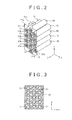
- the plurality of single cells 10 accommodated in the case 100 is placed as illustrated in FIG. 2 .
- an X-axis, a Y-axis, and a Z-axis are axes perpendicular to each other.
- the plurality of single cells 10 can be placed in an arrangement different from the arrangement illustrated in FIG. 2 .
- the number of single cells 10 can be set as appropriate in consideration of a requested output and the like of the battery block 1.
- the plurality of single cells 10 is held by a holder 20. As illustrated in FIG. 1 , the holder 20 holds a central part of each of the single cells 10 in an X-direction. The holder 20 has as many openings 21 as the number of single cells 10 as illustrated in FIG. 3 . The plurality of single cells 10 is placed in line in an X-Y plane. In the example of FIG. 2 , a row of five single cells 10 arranged in a Y-direction, and rows of four single cells 10 arranged in the Y-direction are placed in line along the X-direction.
- the holder 20 holds the central parts of the single cells 10, but can hold other parts (e.g., end parts of the single cells 10). Further, the plurality of single cells 10 can be held by use of a plurality of holders 20.
- the single cell 10 is inserted into the opening 21, and an adhesive is filled into a gap formed between the opening 21 and the single cell 10.
- the adhesive it is possible to use epoxy resin, for example. By filling the adhesive into the gap formed between the opening 21 and the single cell 10, it is possible to fix the single cell 10 to the holder 20.
- an elastically deformable resin frame may be provided in the gap formed between the opening 21 and the single cell 10, so that the single cell 10 is inserted into the holder 20 via the resin frame so as to be held therein.
- the holder 20 can be made of metal such as aluminum, for example.
- a heat dissipation property of the single cells 10 can be improved.
- the single cell 10 may generate heat by charging and discharging, and the like. If the holder 20 is made of metal, the heat generated from the single cells 10 can easily dissipates to the holder 20, thereby making it possible to restrain an increase in temperature of the single cells 10. Note that, even in a case where the holder 20 is made of a resin material or the like having high heat conductivity instead of the metal material, it is also possible to improve the heat dissipation property of the single cells 10.
- the holder 20 is firmly fixed to the case 100.
- As a structure to fix the holder 20 to the case 100 it is possible to use a well-known structure as appropriate.
- the holder 20 can be fixed to the case 100 by use of a bolt.
- the single cell 10 is a so-called cylindrical battery. That is, the single cell 10 extends in a Z-direction, and a sectional shape of the single cell 10 on the X-Y plane is formed in a round shape.
- the single cell 10 it is possible to use a 18650-type battery, for example.
- the 18650-type battery is a cylindrical battery having a diameter of 18 [mm] and a length of 65.0 [mm], and is formed in an elongated shape.
- a secondary battery such as a nickel metal hydride battery or a lithium-ion battery can be used, and instead of the secondary battery, an electric double layer capacitor (a capacitor) can be used.
- the single cell 10 includes a battery outer case 11 and a power generation element accommodated in the battery outer case 11.
- the power generation element is an element that performs charging and discharging, and includes a positive plate, a negative plate, and a separator placed between the positive plate and the negative plate.
- the separator contains an electrolyte.
- the positive plate of the power generation element is electrically connected to a positive terminal 12 provided in one longitudinal-direction end of the single cell 10 in the Z-direction.
- the positive terminal 12 is constituted by a projection surface.
- the negative plate of the power generation element is electrically connected to a negative terminal 13 provided in the other longitudinal-direction end of the single cell 10 in the Z-direction.
- the negative terminal 13 is constituted by a flat surface.
- the positive terminal 12 and the negative terminal 13 constitute the battery outer case 11.
- Respective positive terminals 12 of the plurality of single cells 10 are placed on the same side relative to the holder 20, and are connected to a bus bar 31 as illustrated in FIGS. 1 and 2 .
- the bus bar 31 is made of a material having conductivity, such as metal.
- the bus bar 31 includes connecting portions 31b making contact with the respective positive terminals 12 of the single cells 10, and the number of connecting portions 31b provided herein is the same as the number of single cells 10 (positive terminals 12).
- the connecting portions 31b can be formed by performing press working (punching, bending, or the like) of a single plate-shaped member 31a.
- the connecting portion 31b is formed in a shape projecting from the plate-shaped member 31a toward the positive terminal 12 of the single cell 10.
- the connecting portions 31b are welded to the positive terminals 12.
- the bus bar 31 (the plate-shaped member 31 a) is placed so as to be separated from the plurality of single cells 10 (the positive terminals 12) by a predetermined distance in the Z-direction.
- the connecting portion 31b projecting from the plate-shaped member 31a in the Z-direction is connected to the positive terminal 12 of the single cell 10.
- the whole bus bar 31 serving as a positive bus bar is positively charged by the plurality of single cells 10.
- the bus bar 31 includes a lead portion 31 c, and the lead portion 31c passes an opening 102a formed in the cover 102 of the battery block 1 so as to project outside the case 100.
- a positive terminal P of the battery block 1 is fixed to the lead portion 31c.
- Respective negative terminals 13 of the plurality of single cells 10 are placed on that bottom side of the battery outer case 11 which is opposed to the positive terminals 12 in the longitudinal direction across the holder 20, and are connected to a bus bar 32 (corresponding to the connection member of the present invention).
- the bus bar 32 is made of a material having conductivity, such as metal.
- the bus bar 32 serving as a negative bus bar includes connecting portions 32b making contact with the negative terminals 13 of the single cells 10.
- the number of connecting portions 32b provided herein is the same as the number of single cells 10 (negative terminals 13), and the connecting portions 32b are welded to the negative terminal 13.
- the connecting member 32 includes a lead portion 32c, and the lead portion 32c passes an opening 102b formed in the cover 102 so as to project outside the case 100.
- a negative terminal N of the battery block 1 is fixed to the lead portion 32c.
- the plurality of single cells 10 of the present embodiment is placed in line so that the positive terminals 12 (or the negative terminals 13) of the single cells 10 are oriented in the same direction, so that one bus bar 31 (a first connection member) is connected to respective positive terminals 12 and one bus bar 32 (a second connection member) is connected to respective negative terminals 13 of the single cells 10.
- the plurality of single cells 10 is electrically connected in parallel with each other.
- the present embodiment deals with one example in which all the single cells 10 are connected in parallel with each other so as to constitute the battery block 1 (an assembled battery), but the present embodiment is not limited to this.
- the battery block 1 may be configured such that battery sets of a plurality of single cells 10 connected in parallel are connected in series with each other.
- the battery block 1 can be provided in a vehicle, so as to be used as a power source for causing the vehicle to run. More specifically, a plurality of battery blocks 1 is electrically connected in series with each other so as to constitute a battery pack, so that the battery pack can be provided in the vehicle.
- FIG. 4 is a view illustrating an overall configuration of the bus bar 32 to be connected to the negative terminals 13 of the single cells 10.
- the bus bar 32 of the present embodiment is provided with a plurality of connecting portions 32b respectively corresponding to the plurality of single cells 10 formed integrally with a plate-shaped member 32a (corresponding to a substrate in the present invention), so that the plurality of connecting portions 32b is placed so as to be separated from the negative terminals 13 of the single cell 10 by a predetermined distance (see FIG. 1 ).
- the connecting portion 32b formed in the bus bar 32 of the present embodiment is a connecting portion electrically connected to the negative terminal 13 of the single cell 10, and is used as a fuse that cuts off an electric connection with the single cell 10 (the negative terminal 13) by fusing at the time when a current of a predetermined value or more flows therein.
- the plate-shaped member 32a is a flat plate material with its thickness (plate-thickness) direction being along the Z-direction.
- the plurality of connecting portions 32b is formed by press punching at a predetermined interval at respective positions corresponding to arrangement positions of the single cells 10 (the negative terminals 13) with the Z-direction being taken as a punching direction.
- FIG. 5 is a schematic perspective view illustrating a configuration of the connecting portion 32b of the bus bar 32.
- FIG. 6 is a view illustrating an exemplary configuration of the connecting portion 32b of the bus bar 32 when viewed from each of the XYZ (three-dimensional) directions.
- the connecting portion 32b is configured to include a plurality of extension portions extending generally in parallel with directions perpendicular to the punching direction (the Z-direction).
- an extension portion 321b extends from the plate-shaped member 32a along the X-direction
- an extension portion 322b is bent from the extension portion 321b so as to extend in the Y-direction.
- an extension portion 323b is bent from the extension portion 322b, so as to extend in the X-direction in a direction reverse to an extending direction of the extension portion 321b.
- Each of the extension portions 321b, 322b, 323b can be formed by punching regions S1 to S4 of the plate-shaped member 32a in the Z-direction.
- the extension portion 321b is a plate-shaped extension portion having a width D in the Y-direction, and one end (a root) thereof is formed integrally with the plate-shaped member 32a.
- the extension portion 321b extending in the X-direction is separated from the plate-shaped member 32a via the region S1 in the Y-direction.
- the extension portion 322b is a plate-shaped extension portion having a width D in the X-direction, and is bent from the other end of the extension portion 321b by about 90 degrees in the Y-direction.
- the extension portion 322b extending in the Y-direction is separated from the plate-shaped member 32a via the region S2 in the X-direction.
- the extension portion 323b is a plate-shaped extension portion having a width D in the Y-direction, and is bent from the other end of the extension portion 322b by about 90 degrees in the X-direction so as to extend in the X-direction generally in parallel with the extension portion 321b. That is, the extension portion 323b is an extension portion extending in the X-direction (inwardly) toward the root of the extension portion 321b in a direction reverse to a direction where the extension portion 321b extends in the X-direction.
- the extension portion 323b is separated from the plate-shaped member 32a via the region S3 in the Y-direction and also separated from the plate-shaped member 32a via the region S4 in the X-direction.
- a contacting portion 324b making contact with the negative terminal 13 of the single cell 10 so as to be connected to the negative terminal 13 by welding is formed in a tip end of the extension portion 323b.
- the present embodiment deals with one example in which the contacting portion 324b is formed in a projecting manner inwardly in the Y-direction from the extension portion 323b, but may be formed in any shape according to a positional relationship with the negative terminal 13 of the single cell 10 appropriately. Further, the tip end of the extension portion 323b can be directly connected to the negative terminal 13 of the single cell 10, as the contacting portion 324b. Note that the contacting portion 324b can be formed wider in the X-direction or the Y-direction than each of the extension portions.
- the connecting portion 32b of the present embodiment is formed such that a region with the same size as or a larger size than the negative terminal 13 (a bottom part of the battery outer case 11) of the single cell 10 is punched by press punching.
- the connecting portion 32b is configured such that the plurality of extension portions extended from the plate-shaped member 32a is placed in a spiral manner toward that center of a punched region R in which a central part of the negative terminal 13 is placed.
- the plurality of extension portions is formed in a U-shape as a whole, and the region R where the connecting portion 32b of the plate-shaped member 32a is formed is subjected to punching so as to leave each of the extension portions with the extension portion 321b being as a base end, thereby providing the connecting portion 32b formed integrally with the plate-shaped member 32a in the region R thus punched.
- extension portion 323b of the present embodiment is formed so as to extend from the extension portion 322b in the X-direction in a direction reverse to a direction where the extension portion 321b extends. Because of this, reduction (compactification) of a size of the connecting portion 32b can be achieved.
- the present embodiment exemplifies the connecting portion 32b formed in a U-shape, but the connecting portion 32b may have other shapes.
- the connecting portion 32b may be formed in an L-shape constituted by the extension portions 321b, 322b including bent portions that will be described later.
- the connecting portion 32b is formed so as to project in the Z-direction (the punching direction) from the plate-shaped member 32a toward the negative terminal 13.
- bent portions 331b, 332b bent in the punching direction are formed.
- the bent portion 331b can be formed such that the whole extension portion 321b extending in the X-direction is bent along the X-direction perpendicular to the punching direction.
- the bent portion 331b has the same width D as the extension portion 321b in the Y-direction, and forms a step relative to the extension portion 322b in the Z-direction.
- the bent portion 331b is formed such that a plate-thickness surface is bent in a direction away from the bus bar 32 from a width-direction bending line P1 in the extension portion 321b extending in the X-direction, and further bent from a bending line P2 so as to be generally in parallel with an XY-plane so that the plate-thickness surface approaches the bus bar 32.
- This bending can be performed at the same time with punching or in a step different from the punching.
- the bent portion 332b can be formed such that the whole extension portion 322b extending in the Y-direction is bent along the Y-direction perpendicular to the punching direction. As illustrated in FIG. 6 , the bent portion 332b has the same width D as the extension portion 322b in the X-direction, and forms a step relative to the extension portion 323b in the Z-direction.
- the bent portion 332b is also formed such that its plate-thickness surface is bent in a direction away from the bus bar 32 from a width-direction bending line P3 in the extension portion 322b extending in the Y-direction, and the plate-thickness surface is further bent from a bending line P4 so as to be generally in parallel with the XY-plane so that the plate-thickness surface approaches the bus bar 32.
- the bent portions 331b, 332b are formed by bending the whole plate-thickness surface at origins, i.e., the bending lines (fold lines) P1 to P4 extending in the width direction, in respective regions of the plate-shaped extension portions 321b, 322b.
- the bent portion 331b is formed such that the whole extension portion 321b is bent in a thickness direction along the X-direction perpendicular to the punching direction (an X-Z plane view in FIG. 6 ), and the bent portion 332b is formed such that the whole extension portion 322b is bent in the thickness direction along the Y-direction perpendicular to the punching direction (a Y-Z plane view in FIG. 6 ).
- the bent portion 331b and the bent portion 332b are bent in the punching direction, and are oriented in respective directions (the X-direction, the Y-direction) perpendicular to each other among the directions perpendicular to the punching direction.
- the bent portions 331b, 332b are bent in the same orientation in the Z-direction so as to project toward a side where the negative terminal 13 of the single cell 10 is placed.
- the connecting portion 32 In the battery block 1, when a current flows in the single cell 10 (the negative terminal 13) and the bus bar 32 (the connecting portion 32b), the connecting portion 32 is displaced relative to the negative terminal 13 of the single cell 10 due to thermal expansion/thermal contraction, and is also displaced due to vibration or the like. Because of this, stresses in the XYZ directions act on the connecting portion 32b along with such displacements.
- FIG. 7 is a view illustrating one example of absorption/dispersion of a stress applied to the connecting portion 32b according to a displacement in the longitudinal direction of the single cell 10, i.e., a displacement in the Z-direction in terms of a positional relationship between the bus bar 32 and the single cell 10.
- the whole connecting portion 32b has the same thickness as the plate-shaped member 32a, and its plate-thickness surface faces the Z-direction.
- the whole connecting portion 32b functions as a leaf spring that warps in the thickness direction, so as to absorb/disperse a stress in the thickness direction. That is, a shearing force relative to a lengthwise direction of the plate material which shearing force is perpendicular to the plate-thickness surface is restrained, so that the whole connecting portion 32b in the thickness direction absorbs/disperses the stress acting in the Z-direction.
- the connecting portion 32b connected to the negative terminal 13 of the single cell 10 is displaced in a direction away from the bus bar 32 (the plate-shaped member 32a) (see an upper view in FIG. 7 ), the stress does not act from a direction perpendicular to a press cutout section of the connecting portion 32b, so that a shearing force in the width direction of each of the extension portions 321b, 322b, 323b is restrained, and the each of the extension portions 321b, 322b, 323b warps so as to expand in the thickness direction, thereby absorbing/dispersing the stress.
- each of the extension portions 321b, 322b, 323b warps in the thickness direction so as to approach the bus bar 32 (to be narrowed), thereby absorbing/dispersing a stress. Even at this time, in a state where the stress does not act from the direction perpendicular to the press cutout section of the connecting portion 32b, each of the extension portions 321b, 322b, 323b functions as a leaf spring on the plate-thickness surface.
- FIG. 8 is a view illustrating one example of absorption/dispersion of a stress at the connecting portion 32b according to a displacement in the X-direction (a first direction) perpendicular to the longitudinal direction of the single cell 10.
- the bent portion 331b is displaced so that an inclined surface that is inclined in the Z-direction becomes generally parallel to the XY-plane, and the whole extension portion 321b approaches the bus bar 32 in the Z-direction.
- the bent portion 331b extends in the X-direction so that an angle of that inclined surface of the bent portion 331b which is inclined in the Z-direction becomes gentle.
- a stress applied to the extension portion 321b is absorbed/dispersed and the whole extension portion 321b warps in the thickness direction (the Z-direction) so as to approach the bus bar 32, thereby absorbing/dispersing the stress.
- the bent portion 331b is displaced so that the inclined surface that is inclined in the Z-direction becomes generally perpendicular to the XY-plane and the whole extension portion 321b approaches the bus bar 32 in the Z-direction.
- the bent portion 331b contracts in the X-direction so that the angle of that inclined surface of the bent portion 331b which is inclined in the Z-direction becomes steep.
- a stress applied to the extension portion 321b is absorbed/dispersed and the whole extension portion 321b warps in the thickness direction (the Z-direction) so as to approach the bus bar 32, thereby absorbing/dispersing the stress.
- the inclination of the bent portion 331b in the Z-direction changes relative to the displacement of the connecting portion 32b in the X-direction, so that the bent portion 331b is displaced so as to extend or contract in the X-direction.
- the displacement of the bent portion 331b in the X-direction is converted into warping of the plate-thickness surface of the extension portion 321b in the Z-direction, so that the whole extension portion 321b warps in the thickness direction, and hereby, the stress is absorbed/dispersed relative to the displacement of the connecting portion 32b in the X-direction.
- the whole extension portion 322b can warp in the Z-direction in terms of its thickness direction, and hereby, the stress can be absorbed/dispersed relative to the displacement of the connecting portion 32b in the X-direction.
- FIG. 9 is a view illustrating one example of absorption/dispersion of a stress at the connecting portion 32b according to a displacement in the Y-direction (a second direction) perpendicular to the longitudinal direction of the single cell 10.
- the bent portion 332b is displaced so that its inclined surface that is inclined in the Z-direction becomes generally parallel to the XY-plane and the whole extension portion 322b is distanced from the bus bar 32 in the Z-direction.
- the bent portion 332b extends in the Y-direction so that an angle of that inclined surface of the bent portion 332b which is inclined in the Z-direction becomes gentle.
- a stress applied to the extension portion 322b is absorbed/dispersed and the whole extension portion 322b warps in the thickness direction (the Z-direction) so as to be distanced from the bus bar 32, thereby absorbing/dispersing the stress.
- the bent portion 332b is displaced so that its inclined surface that is inclined in the Z-direction becomes generally perpendicular to the XY-plane and the whole extension portion 322b approaches the bus bar 32 in the Z-direction.
- the bent portion 332b contracts in the Y-direction so that the angle of that inclined surface of the bent portion 332b which is inclined in the Z-direction becomes steep.
- a stress applied to the extension portion 322b is absorbed/dispersed and the whole extension portion 322b warps in the thickness direction (the Z-direction) so as to approach the bus bar 32, thereby absorbing/dispersing the stress.
- the inclination of the bent portion 332b in the Z-direction changes relative to the displacement of the connecting portion 32b in the Y-direction, so that the bent portion 332b is displaced so as to extend or contract in the Y-direction.
- the displacement of the bent portion 332b in the Y-direction is converted into warping of the plate-thickness surface of the extension portion 322b in the Z-direction, so that the whole extension portion 322b warps in the thickness direction, and hereby, the stress is absorbed/dispersed relative to the displacement of the connecting portion 32b in the Y-direction.
- the whole extension portion 321b can warp in the Z-direction in terms of its thickness direction, and hereby, the stress can be absorbed/dispersed relative to the displacement of the connecting portion 32b in the Y-direction.
- the bent portion 331b is formed such that the extension portion 321b is bent in the thickness direction along the X-direction perpendicular to the punching direction
- the bent portion 332b is formed such that the extension portion 322b is bent in the thickness direction along the Y-direction perpendicular to the punching direction.
- the bent portion 331b and the bent portion 332b are inclined so as to face the X-direction and the Y-direction, respectively, which are perpendicular to each other among the directions perpendicular to the punching direction.
- the extension portions 321b, 322b warp like a leaf spring in the thickness direction relative to the displacements in the X-direction and the Y-direction, which are perpendicular to the punching direction, so that stresses applied to the connecting portion 32b in the X-direction and in the Y-direction are absorbed/dispersed by the plate-thickness surface of the connecting portion 32b. Further, even in terms of the displacement in the punching direction, the stress can be absorbed/dispersed by the plate-thickness surface of the connecting portions 32b.
- the connecting portion 32b of the present embodiment has a predetermined fusing characteristic as a fuse, as described above.
- the widths D, in respective directions, of respective extension portions 321b, 322b, 323b constituting the connecting portion 32b can be set to a magnitude that is fused at the time when a current of a predetermined value or more, which is set in advance, flows therein, as the fusing characteristic.
- the width D when the width D is wide, it is difficult to perform fusing (an upper-limit current value relative to the fusing characteristic is high), but when the width D is narrowed, it is easy to perform fusing (the upper-limit current value relative to the fusing characteristic is low).
- the widths D of the extension portions 321b, 322b, 323b are set to be wide or narrow according to fusing specification, it is possible to realize the bus bar 32 which allows the connecting portion 32b to function as a fuse, which can absorb/disperse stresses in respective directions perpendicular to the punching direction by the bent portions 331b, 332b, and which can efficiently absorb/disperse the stresses relative to those displacements in the three-dimensional directions between the single cell 10 and the bus bar 32 which are caused due to vibration or the like.
- FIG. 10 is a schematic perspective view illustrating a modification of the connecting portion 32b of the present embodiment.
- FIG. 11 is a view illustrating a configuration of the connecting portion 32b in the modification illustrated in FIG. 10 and illustrating an exemplary configuration of the connecting portion when viewed from each of three-dimensional directions.
- the connecting portion 32b of the modification is configured such that respective bending directions of two bent portions, i.e., bent portions 331b, 332b are different from each other in the punching direction.
- the bent portion 331b is formed such that a plate-thickness surface thereof is bent in a direction approaching a case-main-body-101 side placed on an opposite side to a negative-terminal-13 side of a single cell 10 and on an outer side relative to a bus bar 32 in the Z-direction, from a width-direction bending line P1 in an extension portion 321b extending in the X-direction, and further, the plate-thickness surface is bent from a bending line P2 so as to be generally in parallel with an XY-plane so that the plate-thickness surface approaches the bus bar 32.
- the bent portion 332b is bent in a direction approaching the negative-terminal-13 side of the single cell 10 in the Z-direction from the extension portion 321b placed on the case-main-body-101 side relative to a plate-shaped part 32a, so as to be formed in the same bending direction as in the example of FIG. 5 .
- the extension portions 321b, 322b warp like a leaf spring on the plate-thickness surface, relative to displacements in the X-direction and the Y-direction, which are perpendicular to the punching direction, and further, the plate-thickness surface of the connecting portion 32b also warps like a leaf spring relative to a displacement in the punching direction, so that the whole connecting portion 32b can absorb/disperse stresses by the plate-thickness surface.
- the modification illustrated in FIG. 10 , etc. can be applied according to a space between the case main body 101 and the bus bar 32 in the Z-direction (see FIG. 1 ), for example, and a distance between the bus bar 32 and the negative terminal 13 of the single cell 10 can be narrowed in comparison with the example of FIG. 5 .
- the extension portions 321b, 322b are formed along the X-direction and the Y-direction, respectively, but the extension portions 321b, 322b may be provided so that the bent portions 331b, 332b face directions perpendicular to each other in respective directions inclined from the X-direction and the Y-direction. That is, the bent portions 331b, 332b may not be provided along the X-direction and the Y-direction, respectively, provided that the bent portions 331b, 332b are provided so as to be perpendicular to each other in respective directions perpendicular to the punching direction.
- the connecting portion 32b can be formed such that a bent portion bent in the same or different bending direction is formed in the extension portion 323b, so that respective bent portions are formed in the extension portions 321b, 322b, 323b.
- at least two of three bent portions can be provided so as to face directions perpendicular to each other among the directions perpendicular to the punching direction.
- the at least two bent portions can be configured so as to be provided in the extension portion 321b and the extension portion 323b, or in the extension portion 322b and the extension portion 323b.
- the extension portions 321b, 322b, 323b are formed integrally with each other in a generally U-shape, and bending parts thereof are generally at 90 degrees, but the present embodiment is not limited to this.
- the connecting portion 32b can be formed such that the extension portions 321b, 322b, 323b are bent at a given angle so that the bent portions 331b, 332b are perpendicular to each other in respective directions perpendicular to the punching direction.
- the bending part can have a shape bent in a round curved shape.
- the present embodiment deals with one example in which the connecting portion 32b having a fuse function is provided in the bus bar 32, which is a negative bus bar, but the present embodiment is also applicable to a connecting portion of the bus bar 31, which is a positive bus bar. That is, in the battery block 1, the connecting portion 32b of the present embodiment can be applied to both of or either one of the positive bus bar and the negative bus bar.
- FIGS. 12 to 14 are views each illustrating Embodiment 2 of the present invention.
- a member having the same function as the member described in Embodiment 1 has the same reference numeral, and a detailed description thereof is omitted.
- the present embodiment mainly describes points different from Embodiment 1.
- FIG. 12 is a schematic perspective view illustrating a configuration of a connecting portion 320b of a bus bar 32 of the present embodiment.
- FIG. 13 is a view illustrating the configuration of the connecting portion 320b of the bus bar 32 and illustrating an exemplary configuration of the connecting portion when viewed from each of three-dimensional directions.
- the connecting portion 320b of the bus bar 32 of the present embodiment includes: an extension portion 341b extending in the Y-direction; an extension portion 342b bent from the extension portion 341b in the X-direction so as to extend in the X-direction; an extension portion 343b bent from the extension portion 342b in the Y-direction so as to extend in the Y-direction in a direction reverse to an extending direction of the extension portion 341b; and an extension portion 344b bent from the extension portion 343b in the X-direction so as to extend in the X-direction in a direction reverse to an extending direction of the extension portion 342b.
- the extension portions 341b, 342b, 343b, 344b are formed integrally with each other from a plate-shaped member 32a with the extension portion 341b being taken as a base end.
- the extension portion 341b is extended from the plate-shaped member 32a so as to extend in the Y-direction so that a plate-thickness surface thereof is generally parallel to a direction perpendicular to the punching direction via the plate-shaped member 32a and a region S1a.
- the extension portions 342b, 343b are also provided so as to be generally parallel to the direction perpendicular to the punching direction via regions S1, S2.
- a contacting portion 345b making contact with a negative terminal 13 of a single cell 10 so as to be connected to the negative terminal 13 by welding is formed in a tip end of the extension portion 344b.
- a bent portion 351b of the present embodiment is formed such that a bending part 361b between the extension portion 341b and the extension portion 342b is bent generally in parallel with the punching direction from a surface perpendicular to the punching direction.
- the bent portion 351b is formed such that a plate-thickness surface of the bending part 361b is bent so as to be generally parallel with the punching direction, along bending lines P5, P6 extending in a first direction inclined from the X-direction toward the Y-direction in the bending part 361b.
- the bending line P5 and the bending line P6 are bending lines provided on the extension portion 341b and the extension portion 342b, respectively: the bending line P5 extends so as to be inclined in the X-direction relative to a width direction of the extension portion 341b extending in the Y-direction; and the bending line P6 extends so as to be inclined in the Y-direction relative to a width direction of the extension portion 341b extending in the X-direction.
- these bending lines P5, P6 are continued linearly so as to form a bending line extending in the first direction.
- the bending member 361b is bent such that its plate-thickness surface becomes generally parallel with the punching direction so that the bent portion 351b includes at least part of a corner 361c of the bending part 361b.
- the plate-thickness surface is placed so as not to become generally parallel with a direction perpendicular to the punching direction.
- a bent portion 352b of the present embodiment is formed such that a bending part 362b between the extension portion 342b and the extension portion 343b is bent generally in parallel with the punching direction from the surface perpendicular to the punching direction.
- the bent portion 352b is formed such that a plate-thickness surface of the bending part 362b is bent so as to be generally parallel with the punching direction, along bending lines P7, P8 extending in a second direction inclined from the Y-direction toward the X-direction in the bending part 362b.
- the second direction is a direction perpendicular to the first direction of the bending part 361b among the directions perpendicular to the punching direction.
- the bending line P7 and the bending line P8 are bending lines provided on the extension portion 342b and the extension portion 343b, respectively: the bending line P7 extends so as to be inclined in the Y-direction relative to a width direction of the extension portion 342b extending in the X-direction; and the bending line P8 extends so as to be inclined in the X-direction relative to a width direction of the extension portion 343b extending in the Y-direction.
- these bending lines P7, P8 are continued linearly so as to form a bending line extending in the second direction.
- a plate-thickness surface of the bending member 362b is bent generally in parallel with the punching direction, so that the bent portion 352b includes at least part of a corner 362c of the bending part 362b.
- the plate-thickness surface is placed so as not to becomes generally parallel with the direction perpendicular to the punching direction.
- their respective plate-thickness surfaces are generally parallel with the punching direction (the Z-direction), and in an XY plan view perpendicular to the Z-direction, the respective plate-thickness surfaces face the first direction and the second direction so as to be perpendicular to each other.
- extension portion 343b is provided with a bent portion 353b formed such that a whole plate-thickness surface thereof is bent in the Z-direction at origins, i.e., bending lines P9, P10 extending in a width direction, similarly to the bent portion shown in Embodiment 1.
- the extension portions 343b, 344b are formed so as to project toward a negative-terminal-13 side of the single cell 10 due to the bent portion 353b.
- FIG. 14 is a view illustrating one example of absorption/dispersion of a stress at the connecting portion 320b according to displacements in the X-direction and the Y-direction perpendicular to a longitudinal direction of the single cell 10 of the present embodiment.
- the plate-thickness surface can warp on the XY-plane, and hereby, stresses can be absorbed/dispersed relative to displacements of the connecting portion 320b in the XY-directions.
- the plate-thickness surface can warp on the XY-plane, and hereby, stresses can be absorbed/dispersed relative to displacements of the connecting portion 320b in the XY-directions.
- those plate-thickness surfaces of the bending parts 361b, 362b which are bent generally in parallel with the punching direction warp in respective directions perpendicular to the punching direction, thereby making it possible to absorb/disperse stresses relative to the displacements in the X-direction and in the Y-direction due to vibration or the like.
- the bending parts 361b, 362b are placed at different positions in the X-direction so as to be distanced from each other, so that there are two axes around which the plate-thickness surfaces for absorbing/dispersing the stresses relative to a displacement of the contacting portion 345b connected to the negative terminal 13 warp. Accordingly, rotational orbits of the XY-plane are allowed at two axes around the bending parts 361b, 362b. For example, in a case where a stress is absorbed/dispersed only by the bent portion 351b, only one rotational orbit is allowed around the bending part 361b. However, if another rotational orbit is allowed around the bending part 362b by the bent portion 352b, the stress can be absorbed/dispersed efficiently by the plate-thickness surfaces warping relative to a whole displacement of the XY-plane.
- the extension portion 343b is formed so as to extend in the Y-direction in a direction reverse to the extending direction of the extension portion 341b
- the extension portion 344 is formed so as to extend in the X-direction in a direction reverse to the extending direction of the extension portion 342b, thereby making it possible to achieve reduction (compactification) of a size of the connecting portion 320b.
- respective bending directions of two bent portions i.e., the bent portions 351b, 352b may be different from each other in a direction generally parallel to the punching direction.
Landscapes
- Engineering & Computer Science (AREA)
- Power Engineering (AREA)
- Microelectronics & Electronic Packaging (AREA)
- Chemical & Material Sciences (AREA)
- Chemical Kinetics & Catalysis (AREA)
- Electrochemistry (AREA)
- General Chemical & Material Sciences (AREA)
- Physics & Mathematics (AREA)
- Thermal Sciences (AREA)
- Combustion & Propulsion (AREA)
- Connection Of Batteries Or Terminals (AREA)
- Electric Double-Layer Capacitors Or The Like (AREA)
- Fuses (AREA)
Abstract
Description
- The present invention relates to a power storage device in which a plurality of storage elements is electrically connected to each other. More particularly, the present invention relates to a bus bar (a connection member) connected to a positive electrode or a negative electrode of each of the storage elements.
- In
Patent Document 1, a positive bus bar for connecting positive electrodes of a plurality of cylindrical batteries and a negative bus bar for connecting negative electrodes thereof are provided. The positive and negative electrodes of the cylindrical batteries are connected to respective bus bars via a fuse (a current limiter). A lead wire is used as the fuse, and when a current of a predetermined value or more such as an excess current flows, fusing is caused due to heat generation, so that electric connection between the bus bar and the positive electrode of the cylindrical battery and/or electric connection between the bus bar and the negative electrode of the cylindrical battery are/is cut off. - Patent Document 1: International Publication No.
2008/121224 - In
Patent Document 1, different fuses are used for the battery and for the bus bar, so that it is necessary to connect the bus bar with the fuse and the cylindrical battery with the fuse, individually. Since the fuse and the bus bar are provided separately, there is such a problem that it is hard to secure a contact point that allows assembly tolerance, vibration displacement, and the like between the bus bar and the cylindrical battery. - On this account, it is necessary to take measures for the fuse in consideration of assembly tolerance and a stress caused by displacement due to vibration or the like. However, when the fuse is thinned, the displacement due to vibration or the like can be easily absorbed, but a current amount to flow is decreased, which causes an increase in an amount of heat generation and restrains an allowable current amount to flow. In the meantime, when the fuse is made large to increase a current amount to flow, an increase in heat generation and a restraint of the allowable current amount can be relaxed, but the displacement due to vibration or the like is hard to be absorbed.
- In view of this, an object of the present invention is to provide a connection member configured to electrically connect respective storage elements to each other in a power storage device constituted by a plurality of storage elements, which connection member has a fusing characteristic as a fuse and is able to efficiently absorb/disperse stresses relative to displacements in three-dimensional directions between the storage elements and the connection member due to vibration or the like.
- A connection member according to a first invention of the present application is a connection member configured to electrically connect respective storage elements to each other in a power storage device constituted by a plurality of storage elements. The connection member includes: a substrate; and a plurality of connecting portions connected to electrodes of the respective storage elements and configured to cut off electric connection with the storage elements by fusing at the time when a current of a predetermined value or more flows therein. The connecting portion is formed by performing punching on the substrate and includes at least two bent portions bent in a punching direction. Further, one of the bent portions is bent along a first direction perpendicular to the punching direction, and the other one of the bent portions is bent along a second direction perpendicular to the punching direction and perpendicular to the first direction.
- In the first aspect of the present invention, the connecting portion formed integrally with the substrate includes at least two bent portions bent in the punching direction. Further, the at least two bent portions are bent along the first direction and the second direction perpendicular to the punching direction and perpendicular to each other. On this account, stresses to act in respective directions perpendicular to the punching direction are absorbed/dispersed by bending displacements of respective bent portions bent in a thickness direction, and a stress to act in the punching direction is absorbed/dispersed by a displacement of the whole connection member in the thickness direction.
- Accordingly, the connection member has a fusing characteristic as a current limiter (a fuse), and can efficiently absorb/disperse stresses relative to those displacements in three-dimensional directions between the storage element and the connection member which are caused due to vibration or the like.
- The connecting portion can be configured to include a first extension portion extending in the first direction, and a second extension portion extending from the first extension portion in the second direction. The at least two bent portions can be formed by bending the first extension portion and the second extension portion in the punching direction along their respective extending directions. Further, the connecting portion can be configured to further include a third extension portion extending from the second extension portion in the first direction in a direction reverse to the extending direction of the first extension portion.
- The connecting portion can include a first extension portion extending generally in parallel with a direction perpendicular to the punching direction, a second extension portion bent from the first extension portion and extending generally in parallel with the direction perpendicular to the punching direction, and a third extension portion bent from the second extension portion and extending generally in parallel with the direction perpendicular to the punching direction. At this time, one of the bent portions can be formed such that a part bending between the first extension portion and the second extension portion is bent from a surface perpendicular to the punching direction along the first direction so as to become generally parallel with the punching direction. Further, the other one of the bent portions can be formed such that a part bending between the second extension portion and the third extension portion is bent from the surface perpendicular to the punching direction along the second direction so as to become generally parallel with the punching direction. Further, the third extension portion can be formed so as to extend from the second extension portion in a direction reverse to the extending direction of the first extension portion.
- Respective bending directions of the at least two bent portions can be configured to be the same or different from each other in the punching direction.
- The storage element can be configured as a cylindrical storage element having a longitudinal direction. The plurality of storage elements is arranged in line so that positive electrodes or negative electrodes placed in longitudinal-direction end parts thereof are oriented in the same direction. The connection member can be configured to be connected to respective negative electrodes of the plurality of storage elements.
- With the connection member, it is possible to configure a power storage device including a plurality of storage elements electrically connected in parallel with each other by the connection member.
-
- [
FIG. 1] FIG. 1 is a view illustrating an internal configuration of a battery block inEmbodiment 1. - [
FIG. 2] FIG. 2 is a view illustrating an arrangement state of a plurality of single cells inEmbodiment 1. - [
FIG. 3] FIG. 3 is a front view illustrating a holder for holding the single cells of the battery block inEmbodiment 1. - [
FIG. 4] FIG. 4 is a view illustrating a bus bar to be connected to negative terminals of the single cells inEmbodiment 1. - [
FIG. 5] FIG. 5 is a schematic perspective view illustrating a configuration of a connecting portion of the bus bar inEmbodiment 1. - [
FIG. 6] FIG. 6 is a view illustrating the configuration of the connecting portion of the bus bar inEmbodiment 1 and illustrating an exemplary configuration of the connecting portion when viewed from each of three-dimensional directions. - [
FIG. 7] FIG. 7 is a view illustrating one example of absorption/dispersion of a stress at the connecting portion according to a displacement in a longitudinal direction of the single cell, inEmbodiment 1. - [
FIG. 8] FIG. 8 is a view illustrating one example of absorption/dispersion of a stress at the connecting portion according to a displacement in a first direction perpendicular to the longitudinal direction of the single cell, inEmbodiment 1. - [
FIG. 9] FIG. 9 is a view illustrating one example of absorption/dispersion of a stress at the connecting portion according to displacement in a second direction perpendicular to the longitudinal direction of the single cell, inEmbodiment 1. - [
FIG. 10] FIG. 10 is a schematic perspective view illustrating a modification of the connecting portion of the bus bar inEmbodiment 1. - [
FIG. 11] FIG. 11 is a view illustrating a configuration of the connecting portion in the modification illustrated inFIG. 10 and illustrating an exemplary configuration of the connecting portion when viewed from each of three-dimensional directions. - [
FIG. 12] FIG. 12 is a schematic perspective view illustrating a configuration of a connecting portion of a bus bar inEmbodiment 2. - [
FIG. 13] FIG. 13 is a view illustrating the configuration of the connecting portion of the bus bar inEmbodiment 2 and illustrating an exemplary configuration of the connecting portion when viewed from each of three-dimensional directions. - [
FIG. 14] FIG. 14 is a view illustrating one example of absorption/dispersion of a stress at the connecting portion according to a displacement in a direction perpendicular to a longitudinal direction of the single cell inEmbodiment 2. - The following describes embodiments of the present invention.
-
FIGS. 1 to 11 are views eachillustrating Embodiment 1 of the present invention.FIG. 1 is a view illustrating an internal structure of a battery block (corresponding to a power storage device) according to the present embodiment. - The
battery block 1 includes a plurality of single cells (corresponding to storage elements) 10 and acase 100 for accommodating the plurality ofsingle cells 10 therein. Thecase 100 includes a casemain body 101 and acover 102. Thecover 102 is fixed to an upper end of the casemain body 101, and closes an opening 101a formed in the casemain body 101. The casemain body 101 and thecover 102 can be made of resin, for example. - The plurality of
single cells 10 accommodated in thecase 100 is placed as illustrated inFIG. 2 . InFIGS. 1 and2 , an X-axis, a Y-axis, and a Z-axis are axes perpendicular to each other. Note that the plurality ofsingle cells 10 can be placed in an arrangement different from the arrangement illustrated inFIG. 2 . Further, the number ofsingle cells 10 can be set as appropriate in consideration of a requested output and the like of thebattery block 1. - The plurality of
single cells 10 is held by aholder 20. As illustrated inFIG. 1 , theholder 20 holds a central part of each of thesingle cells 10 in an X-direction. Theholder 20 has asmany openings 21 as the number ofsingle cells 10 as illustrated inFIG. 3 . The plurality ofsingle cells 10 is placed in line in an X-Y plane. In the example ofFIG. 2 , a row of fivesingle cells 10 arranged in a Y-direction, and rows of foursingle cells 10 arranged in the Y-direction are placed in line along the X-direction. - Note that, in the present embodiment, the
holder 20 holds the central parts of thesingle cells 10, but can hold other parts (e.g., end parts of the single cells 10). Further, the plurality ofsingle cells 10 can be held by use of a plurality ofholders 20. - The
single cell 10 is inserted into theopening 21, and an adhesive is filled into a gap formed between theopening 21 and thesingle cell 10. As the adhesive, it is possible to use epoxy resin, for example. By filling the adhesive into the gap formed between theopening 21 and thesingle cell 10, it is possible to fix thesingle cell 10 to theholder 20. Further, instead of the epoxy resin, an elastically deformable resin frame may be provided in the gap formed between theopening 21 and thesingle cell 10, so that thesingle cell 10 is inserted into theholder 20 via the resin frame so as to be held therein. - The
holder 20 can be made of metal such as aluminum, for example. When theholder 20 is made of metal, a heat dissipation property of thesingle cells 10 can be improved. Thesingle cell 10 may generate heat by charging and discharging, and the like. If theholder 20 is made of metal, the heat generated from thesingle cells 10 can easily dissipates to theholder 20, thereby making it possible to restrain an increase in temperature of thesingle cells 10. Note that, even in a case where theholder 20 is made of a resin material or the like having high heat conductivity instead of the metal material, it is also possible to improve the heat dissipation property of thesingle cells 10. - The
holder 20 is firmly fixed to thecase 100. As a structure to fix theholder 20 to thecase 100, it is possible to use a well-known structure as appropriate. For example, theholder 20 can be fixed to thecase 100 by use of a bolt. - The
single cell 10 is a so-called cylindrical battery. That is, thesingle cell 10 extends in a Z-direction, and a sectional shape of thesingle cell 10 on the X-Y plane is formed in a round shape. As thesingle cell 10, it is possible to use a 18650-type battery, for example. The 18650-type battery is a cylindrical battery having a diameter of 18 [mm] and a length of 65.0 [mm], and is formed in an elongated shape. Further, as thesingle cell 10, a secondary battery such as a nickel metal hydride battery or a lithium-ion battery can be used, and instead of the secondary battery, an electric double layer capacitor (a capacitor) can be used. - The
single cell 10 includes a batteryouter case 11 and a power generation element accommodated in the batteryouter case 11. The power generation element is an element that performs charging and discharging, and includes a positive plate, a negative plate, and a separator placed between the positive plate and the negative plate. The separator contains an electrolyte. - The positive plate of the power generation element is electrically connected to a
positive terminal 12 provided in one longitudinal-direction end of thesingle cell 10 in the Z-direction. Thepositive terminal 12 is constituted by a projection surface. The negative plate of the power generation element is electrically connected to anegative terminal 13 provided in the other longitudinal-direction end of thesingle cell 10 in the Z-direction. Thenegative terminal 13 is constituted by a flat surface. Thepositive terminal 12 and thenegative terminal 13 constitute the batteryouter case 11. - Respective
positive terminals 12 of the plurality ofsingle cells 10 are placed on the same side relative to theholder 20, and are connected to abus bar 31 as illustrated inFIGS. 1 and2 . Thebus bar 31 is made of a material having conductivity, such as metal. Thebus bar 31 includes connectingportions 31b making contact with the respectivepositive terminals 12 of thesingle cells 10, and the number of connectingportions 31b provided herein is the same as the number of single cells 10 (positive terminals 12). - The connecting
portions 31b can be formed by performing press working (punching, bending, or the like) of a single plate-shapedmember 31a. The connectingportion 31b is formed in a shape projecting from the plate-shapedmember 31a toward thepositive terminal 12 of thesingle cell 10. The connectingportions 31b are welded to thepositive terminals 12. - The bus bar 31 (the plate-shaped
member 31 a) is placed so as to be separated from the plurality of single cells 10 (the positive terminals 12) by a predetermined distance in the Z-direction. The connectingportion 31b projecting from the plate-shapedmember 31a in the Z-direction is connected to thepositive terminal 12 of thesingle cell 10. Thewhole bus bar 31 serving as a positive bus bar is positively charged by the plurality ofsingle cells 10. - The
bus bar 31 includes alead portion 31 c, and thelead portion 31c passes anopening 102a formed in thecover 102 of thebattery block 1 so as to project outside thecase 100. A positive terminal P of thebattery block 1 is fixed to thelead portion 31c. - Respective
negative terminals 13 of the plurality ofsingle cells 10 are placed on that bottom side of the batteryouter case 11 which is opposed to thepositive terminals 12 in the longitudinal direction across theholder 20, and are connected to a bus bar 32 (corresponding to the connection member of the present invention). Thebus bar 32 is made of a material having conductivity, such as metal. Thebus bar 32 serving as a negative bus bar includes connectingportions 32b making contact with thenegative terminals 13 of thesingle cells 10. The number of connectingportions 32b provided herein is the same as the number of single cells 10 (negative terminals 13), and the connectingportions 32b are welded to thenegative terminal 13. - Further, the connecting
member 32 includes alead portion 32c, and thelead portion 32c passes anopening 102b formed in thecover 102 so as to project outside thecase 100. A negative terminal N of thebattery block 1 is fixed to thelead portion 32c. - The plurality of
single cells 10 of the present embodiment is placed in line so that the positive terminals 12 (or the negative terminals 13) of thesingle cells 10 are oriented in the same direction, so that one bus bar 31 (a first connection member) is connected to respectivepositive terminals 12 and one bus bar 32 (a second connection member) is connected to respectivenegative terminals 13 of thesingle cells 10. Hereby, the plurality ofsingle cells 10 is electrically connected in parallel with each other. - Note that the present embodiment deals with one example in which all the
single cells 10 are connected in parallel with each other so as to constitute the battery block 1 (an assembled battery), but the present embodiment is not limited to this. For example, thebattery block 1 may be configured such that battery sets of a plurality ofsingle cells 10 connected in parallel are connected in series with each other. - Further, the
battery block 1 can be provided in a vehicle, so as to be used as a power source for causing the vehicle to run. More specifically, a plurality ofbattery blocks 1 is electrically connected in series with each other so as to constitute a battery pack, so that the battery pack can be provided in the vehicle. - Next will be described the bus bar 32 (the second connection member) in detail.
FIG. 4 is a view illustrating an overall configuration of thebus bar 32 to be connected to thenegative terminals 13 of thesingle cells 10. Similarly to thebus bar 31, thebus bar 32 of the present embodiment is provided with a plurality of connectingportions 32b respectively corresponding to the plurality ofsingle cells 10 formed integrally with a plate-shapedmember 32a (corresponding to a substrate in the present invention), so that the plurality of connectingportions 32b is placed so as to be separated from thenegative terminals 13 of thesingle cell 10 by a predetermined distance (seeFIG. 1 ). - The connecting
portion 32b formed in thebus bar 32 of the present embodiment is a connecting portion electrically connected to thenegative terminal 13 of thesingle cell 10, and is used as a fuse that cuts off an electric connection with the single cell 10 (the negative terminal 13) by fusing at the time when a current of a predetermined value or more flows therein. - The plate-shaped
member 32a is a flat plate material with its thickness (plate-thickness) direction being along the Z-direction. As illustrated inFIG. 4 , the plurality of connectingportions 32b is formed by press punching at a predetermined interval at respective positions corresponding to arrangement positions of the single cells 10 (the negative terminals 13) with the Z-direction being taken as a punching direction. -
FIG. 5 is a schematic perspective view illustrating a configuration of the connectingportion 32b of thebus bar 32.FIG. 6 is a view illustrating an exemplary configuration of the connectingportion 32b of thebus bar 32 when viewed from each of the XYZ (three-dimensional) directions. - As illustrated in
FIGS. 5 and6 , the connectingportion 32b is configured to include a plurality of extension portions extending generally in parallel with directions perpendicular to the punching direction (the Z-direction). Among the directions perpendicular to the punching direction (the Z-direction), anextension portion 321b extends from the plate-shapedmember 32a along the X-direction, and anextension portion 322b is bent from theextension portion 321b so as to extend in the Y-direction. Further, anextension portion 323b is bent from theextension portion 322b, so as to extend in the X-direction in a direction reverse to an extending direction of theextension portion 321b. Each of theextension portions member 32a in the Z-direction. - The
extension portion 321b is a plate-shaped extension portion having a width D in the Y-direction, and one end (a root) thereof is formed integrally with the plate-shapedmember 32a. Theextension portion 321b extending in the X-direction is separated from the plate-shapedmember 32a via the region S1 in the Y-direction. - The
extension portion 322b is a plate-shaped extension portion having a width D in the X-direction, and is bent from the other end of theextension portion 321b by about 90 degrees in the Y-direction. Theextension portion 322b extending in the Y-direction is separated from the plate-shapedmember 32a via the region S2 in the X-direction. - The
extension portion 323b is a plate-shaped extension portion having a width D in the Y-direction, and is bent from the other end of theextension portion 322b by about 90 degrees in the X-direction so as to extend in the X-direction generally in parallel with theextension portion 321b. That is, theextension portion 323b is an extension portion extending in the X-direction (inwardly) toward the root of theextension portion 321b in a direction reverse to a direction where theextension portion 321b extends in the X-direction. Theextension portion 323b is separated from the plate-shapedmember 32a via the region S3 in the Y-direction and also separated from the plate-shapedmember 32a via the region S4 in the X-direction. - A contacting
portion 324b making contact with thenegative terminal 13 of thesingle cell 10 so as to be connected to thenegative terminal 13 by welding is formed in a tip end of theextension portion 323b. The present embodiment deals with one example in which the contactingportion 324b is formed in a projecting manner inwardly in the Y-direction from theextension portion 323b, but may be formed in any shape according to a positional relationship with thenegative terminal 13 of thesingle cell 10 appropriately. Further, the tip end of theextension portion 323b can be directly connected to thenegative terminal 13 of thesingle cell 10, as the contactingportion 324b. Note that the contactingportion 324b can be formed wider in the X-direction or the Y-direction than each of the extension portions. - As such, the connecting
portion 32b of the present embodiment is formed such that a region with the same size as or a larger size than the negative terminal 13 (a bottom part of the battery outer case 11) of thesingle cell 10 is punched by press punching. The connectingportion 32b is configured such that the plurality of extension portions extended from the plate-shapedmember 32a is placed in a spiral manner toward that center of a punched region R in which a central part of thenegative terminal 13 is placed. - In the present embodiment, the plurality of extension portions is formed in a U-shape as a whole, and the region R where the connecting
portion 32b of the plate-shapedmember 32a is formed is subjected to punching so as to leave each of the extension portions with theextension portion 321b being as a base end, thereby providing the connectingportion 32b formed integrally with the plate-shapedmember 32a in the region R thus punched. - Note that the
extension portion 323b of the present embodiment is formed so as to extend from theextension portion 322b in the X-direction in a direction reverse to a direction where theextension portion 321b extends. Because of this, reduction (compactification) of a size of the connectingportion 32b can be achieved. - Further, the present embodiment exemplifies the connecting
portion 32b formed in a U-shape, but the connectingportion 32b may have other shapes. For example, the connectingportion 32b may be formed in an L-shape constituted by theextension portions - As illustrated in
FIG. 6 , the connectingportion 32b is formed so as to project in the Z-direction (the punching direction) from the plate-shapedmember 32a toward thenegative terminal 13. In theextension portions bent portions bent portion 331b can be formed such that thewhole extension portion 321b extending in the X-direction is bent along the X-direction perpendicular to the punching direction. Thebent portion 331b has the same width D as theextension portion 321b in the Y-direction, and forms a step relative to theextension portion 322b in the Z-direction. - More specifically, the
bent portion 331b is formed such that a plate-thickness surface is bent in a direction away from thebus bar 32 from a width-direction bending line P1 in theextension portion 321b extending in the X-direction, and further bent from a bending line P2 so as to be generally in parallel with an XY-plane so that the plate-thickness surface approaches thebus bar 32. This bending can be performed at the same time with punching or in a step different from the punching. - The
bent portion 332b can be formed such that thewhole extension portion 322b extending in the Y-direction is bent along the Y-direction perpendicular to the punching direction. As illustrated inFIG. 6 , thebent portion 332b has the same width D as theextension portion 322b in the X-direction, and forms a step relative to theextension portion 323b in the Z-direction. Similarly to thebent portion 331b, thebent portion 332b is also formed such that its plate-thickness surface is bent in a direction away from thebus bar 32 from a width-direction bending line P3 in theextension portion 322b extending in the Y-direction, and the plate-thickness surface is further bent from a bending line P4 so as to be generally in parallel with the XY-plane so that the plate-thickness surface approaches thebus bar 32. - Here, a relationship between the
bent portions FIG. 6 , thebent portions extension portions - That is, the
bent portion 331b is formed such that thewhole extension portion 321b is bent in a thickness direction along the X-direction perpendicular to the punching direction (an X-Z plane view inFIG. 6 ), and thebent portion 332b is formed such that thewhole extension portion 322b is bent in the thickness direction along the Y-direction perpendicular to the punching direction (a Y-Z plane view inFIG. 6 ). - Accordingly, the
bent portion 331b and thebent portion 332b are bent in the punching direction, and are oriented in respective directions (the X-direction, the Y-direction) perpendicular to each other among the directions perpendicular to the punching direction. Here, thebent portions negative terminal 13 of thesingle cell 10 is placed. - In the
battery block 1, when a current flows in the single cell 10 (the negative terminal 13) and the bus bar 32 (the connectingportion 32b), the connectingportion 32 is displaced relative to thenegative terminal 13 of thesingle cell 10 due to thermal expansion/thermal contraction, and is also displaced due to vibration or the like. Because of this, stresses in the XYZ directions act on the connectingportion 32b along with such displacements. -
FIG. 7 is a view illustrating one example of absorption/dispersion of a stress applied to the connectingportion 32b according to a displacement in the longitudinal direction of thesingle cell 10, i.e., a displacement in the Z-direction in terms of a positional relationship between thebus bar 32 and thesingle cell 10. - As illustrated in
FIG. 7 , the whole connectingportion 32b has the same thickness as the plate-shapedmember 32a, and its plate-thickness surface faces the Z-direction. On this account, with respect to a displacement between thesingle cell 10 and the connectingportion 32b in the Z-direction, the whole connectingportion 32b functions as a leaf spring that warps in the thickness direction, so as to absorb/disperse a stress in the thickness direction. That is, a shearing force relative to a lengthwise direction of the plate material which shearing force is perpendicular to the plate-thickness surface is restrained, so that the whole connectingportion 32b in the thickness direction absorbs/disperses the stress acting in the Z-direction. - Accordingly, even if the connecting
portion 32b connected to thenegative terminal 13 of thesingle cell 10 is displaced in a direction away from the bus bar 32 (the plate-shapedmember 32a) (see an upper view inFIG. 7 ), the stress does not act from a direction perpendicular to a press cutout section of the connectingportion 32b, so that a shearing force in the width direction of each of theextension portions extension portions - Further, in a case where the connecting
portion 32b connected to thenegative terminal 13 of thesingle cell 10 is displaced in a direction approaching the bus bar 32 (the plate-shapedmember 32a) (see a lower view inFIG. 7 ), each of theextension portions portion 32b, each of theextension portions -
FIG. 8 is a view illustrating one example of absorption/dispersion of a stress at the connectingportion 32b according to a displacement in the X-direction (a first direction) perpendicular to the longitudinal direction of thesingle cell 10. - As illustrated in
FIG. 8 , for example, in a case where thesingle cell 10 is displaced in a direction away from the plate-shapedmember 32a, along theextension portion 321b extending in the X-direction (a displacement in the X-direction in which the region S4 is widened and the region S2 is narrowed in the X-direction), thebent portion 331b is displaced so that an inclined surface that is inclined in the Z-direction becomes generally parallel to the XY-plane, and thewhole extension portion 321b approaches thebus bar 32 in the Z-direction. In the displacement of thesingle cell 10 in the X-direction at this time, thebent portion 331b extends in the X-direction so that an angle of that inclined surface of thebent portion 331b which is inclined in the Z-direction becomes gentle. Hereby, a stress applied to theextension portion 321b is absorbed/dispersed and thewhole extension portion 321b warps in the thickness direction (the Z-direction) so as to approach thebus bar 32, thereby absorbing/dispersing the stress. - In the meantime, for example, in a case where the
single cell 10 is displaced in a direction approaching the plate-shapedmember 32a, along theextension portion 321b extending in the X-direction (a displacement in the X-direction in which the region S2 is widened and the region S4 is narrowed in the X-direction), thebent portion 331b is displaced so that the inclined surface that is inclined in the Z-direction becomes generally perpendicular to the XY-plane and thewhole extension portion 321b approaches thebus bar 32 in the Z-direction. At this time, in terms of a stress caused due to the displacement of thesingle cell 10 in the X-direction, thebent portion 331b contracts in the X-direction so that the angle of that inclined surface of thebent portion 331b which is inclined in the Z-direction becomes steep. Hereby, a stress applied to theextension portion 321b is absorbed/dispersed and thewhole extension portion 321b warps in the thickness direction (the Z-direction) so as to approach thebus bar 32, thereby absorbing/dispersing the stress. - Thus, the inclination of the
bent portion 331b in the Z-direction changes relative to the displacement of the connectingportion 32b in the X-direction, so that thebent portion 331b is displaced so as to extend or contract in the X-direction. The displacement of thebent portion 331b in the X-direction is converted into warping of the plate-thickness surface of theextension portion 321b in the Z-direction, so that thewhole extension portion 321b warps in the thickness direction, and hereby, the stress is absorbed/dispersed relative to the displacement of the connectingportion 32b in the X-direction. Note that, at the time when theextension portion 321b is displaced in the Z-direction so as to approach thebus bar 32 relative to the displacement in the X-direction, thewhole extension portion 322b can warp in the Z-direction in terms of its thickness direction, and hereby, the stress can be absorbed/dispersed relative to the displacement of the connectingportion 32b in the X-direction. -
FIG. 9 is a view illustrating one example of absorption/dispersion of a stress at the connectingportion 32b according to a displacement in the Y-direction (a second direction) perpendicular to the longitudinal direction of thesingle cell 10. - As illustrated in
FIG. 9 , for example, in a case where thesingle cell 10 is displaced along theextension portion 322b extending in the Y-direction so that the region S3 is narrowed in the Y-direction, thebent portion 332b is displaced so that its inclined surface that is inclined in the Z-direction becomes generally parallel to the XY-plane and thewhole extension portion 322b is distanced from thebus bar 32 in the Z-direction. At this time, in terms of a stress caused due to the displacement of thesingle cell 10 in the Y-direction, thebent portion 332b extends in the Y-direction so that an angle of that inclined surface of thebent portion 332b which is inclined in the Z-direction becomes gentle. Hereby, a stress applied to theextension portion 322b is absorbed/dispersed and thewhole extension portion 322b warps in the thickness direction (the Z-direction) so as to be distanced from thebus bar 32, thereby absorbing/dispersing the stress. - In the meantime, for example, in a case where the
single cell 10 is displaced along theextension portion 322b extending in the Y-direction so that the region S3 is widened in the Y-direction, thebent portion 332b is displaced so that its inclined surface that is inclined in the Z-direction becomes generally perpendicular to the XY-plane and thewhole extension portion 322b approaches thebus bar 32 in the Z-direction. At this time, in terms of a stress caused due to the displacement of thesingle cell 10 in the Y-direction, thebent portion 332b contracts in the Y-direction so that the angle of that inclined surface of thebent portion 332b which is inclined in the Z-direction becomes steep. Hereby, a stress applied to theextension portion 322b is absorbed/dispersed and thewhole extension portion 322b warps in the thickness direction (the Z-direction) so as to approach thebus bar 32, thereby absorbing/dispersing the stress. - Thus, the inclination of the
bent portion 332b in the Z-direction changes relative to the displacement of the connectingportion 32b in the Y-direction, so that thebent portion 332b is displaced so as to extend or contract in the Y-direction. The displacement of thebent portion 332b in the Y-direction is converted into warping of the plate-thickness surface of theextension portion 322b in the Z-direction, so that thewhole extension portion 322b warps in the thickness direction, and hereby, the stress is absorbed/dispersed relative to the displacement of the connectingportion 32b in the Y-direction. Note that, even in the displacement in the Y-direction, thewhole extension portion 321b can warp in the Z-direction in terms of its thickness direction, and hereby, the stress can be absorbed/dispersed relative to the displacement of the connectingportion 32b in the Y-direction. - In the present embodiment, the
bent portion 331b is formed such that theextension portion 321b is bent in the thickness direction along the X-direction perpendicular to the punching direction, and thebent portion 332b is formed such that theextension portion 322b is bent in the thickness direction along the Y-direction perpendicular to the punching direction. Thebent portion 331b and thebent portion 332b are inclined so as to face the X-direction and the Y-direction, respectively, which are perpendicular to each other among the directions perpendicular to the punching direction. - On this account, the
extension portions portion 32b in the X-direction and in the Y-direction are absorbed/dispersed by the plate-thickness surface of the connectingportion 32b. Further, even in terms of the displacement in the punching direction, the stress can be absorbed/dispersed by the plate-thickness surface of the connectingportions 32b. Accordingly, it is possible to restrain a shearing force from acting on the press cutout section of the connectingportion 32b, thereby making it possible to efficiently absorb/disperse stresses relative to those displacements in three-dimensional directions between thesingle cell 10 and thebus bar 32 which are caused due to vibration or the like. - Here, the connecting
portion 32b of the present embodiment has a predetermined fusing characteristic as a fuse, as described above. In view of this, the widths D, in respective directions, ofrespective extension portions portion 32b can be set to a magnitude that is fused at the time when a current of a predetermined value or more, which is set in advance, flows therein, as the fusing characteristic. - For example, when the width D is wide, it is difficult to perform fusing (an upper-limit current value relative to the fusing characteristic is high), but when the width D is narrowed, it is easy to perform fusing (the upper-limit current value relative to the fusing characteristic is low). As such, when the widths D of the
extension portions bus bar 32 which allows the connectingportion 32b to function as a fuse, which can absorb/disperse stresses in respective directions perpendicular to the punching direction by thebent portions single cell 10 and thebus bar 32 which are caused due to vibration or the like. -
FIG. 10 is a schematic perspective view illustrating a modification of the connectingportion 32b of the present embodiment.FIG. 11 is a view illustrating a configuration of the connectingportion 32b in the modification illustrated inFIG. 10 and illustrating an exemplary configuration of the connecting portion when viewed from each of three-dimensional directions. - As illustrated in
FIGS. 10 ,11 , the connectingportion 32b of the modification is configured such that respective bending directions of two bent portions, i.e.,bent portions - More specifically, the
bent portion 331b is formed such that a plate-thickness surface thereof is bent in a direction approaching a case-main-body-101 side placed on an opposite side to a negative-terminal-13 side of asingle cell 10 and on an outer side relative to abus bar 32 in the Z-direction, from a width-direction bending line P1 in anextension portion 321b extending in the X-direction, and further, the plate-thickness surface is bent from a bending line P2 so as to be generally in parallel with an XY-plane so that the plate-thickness surface approaches thebus bar 32. In the meantime, thebent portion 332b is bent in a direction approaching the negative-terminal-13 side of thesingle cell 10 in the Z-direction from theextension portion 321b placed on the case-main-body-101 side relative to a plate-shapedpart 32a, so as to be formed in the same bending direction as in the example ofFIG. 5 . - Even in the present modification, as described above, the
extension portions portion 32b also warps like a leaf spring relative to a displacement in the punching direction, so that the whole connectingportion 32b can absorb/disperse stresses by the plate-thickness surface. - The modification illustrated in
FIG. 10 , etc., can be applied according to a space between the casemain body 101 and thebus bar 32 in the Z-direction (seeFIG. 1 ), for example, and a distance between thebus bar 32 and thenegative terminal 13 of thesingle cell 10 can be narrowed in comparison with the example ofFIG. 5 . - Note that, in the present embodiment, the
extension portions extension portions bent portions bent portions bent portions - Further, the connecting
portion 32b can be formed such that a bent portion bent in the same or different bending direction is formed in theextension portion 323b, so that respective bent portions are formed in theextension portions extension portion 321b and theextension portion 323b, or in theextension portion 322b and theextension portion 323b. - Further, in the present embodiment, the
extension portions portion 32b can be formed such that theextension portions bent portions - Note that the present embodiment deals with one example in which the connecting
portion 32b having a fuse function is provided in thebus bar 32, which is a negative bus bar, but the present embodiment is also applicable to a connecting portion of thebus bar 31, which is a positive bus bar. That is, in thebattery block 1, the connectingportion 32b of the present embodiment can be applied to both of or either one of the positive bus bar and the negative bus bar. -
FIGS. 12 to 14 are views each illustratingEmbodiment 2 of the present invention. In the present embodiment, a member having the same function as the member described inEmbodiment 1 has the same reference numeral, and a detailed description thereof is omitted. The present embodiment mainly describes points different fromEmbodiment 1. -
FIG. 12 is a schematic perspective view illustrating a configuration of a connectingportion 320b of abus bar 32 of the present embodiment.FIG. 13 is a view illustrating the configuration of the connectingportion 320b of thebus bar 32 and illustrating an exemplary configuration of the connecting portion when viewed from each of three-dimensional directions. - The connecting
portion 320b of thebus bar 32 of the present embodiment includes: anextension portion 341b extending in the Y-direction; anextension portion 342b bent from theextension portion 341b in the X-direction so as to extend in the X-direction; anextension portion 343b bent from theextension portion 342b in the Y-direction so as to extend in the Y-direction in a direction reverse to an extending direction of theextension portion 341b; and anextension portion 344b bent from theextension portion 343b in the X-direction so as to extend in the X-direction in a direction reverse to an extending direction of theextension portion 342b. Theextension portions member 32a with theextension portion 341b being taken as a base end. - The
extension portion 341b is extended from the plate-shapedmember 32a so as to extend in the Y-direction so that a plate-thickness surface thereof is generally parallel to a direction perpendicular to the punching direction via the plate-shapedmember 32a and a region S1a. Theextension portions Embodiment 1, a contactingportion 345b making contact with anegative terminal 13 of asingle cell 10 so as to be connected to thenegative terminal 13 by welding is formed in a tip end of theextension portion 344b. - A
bent portion 351b of the present embodiment is formed such that a bendingpart 361b between theextension portion 341b and theextension portion 342b is bent generally in parallel with the punching direction from a surface perpendicular to the punching direction. At this time, thebent portion 351b is formed such that a plate-thickness surface of the bendingpart 361b is bent so as to be generally parallel with the punching direction, along bending lines P5, P6 extending in a first direction inclined from the X-direction toward the Y-direction in the bendingpart 361b. - The bending line P5 and the bending line P6 are bending lines provided on the
extension portion 341b and theextension portion 342b, respectively: the bending line P5 extends so as to be inclined in the X-direction relative to a width direction of theextension portion 341b extending in the Y-direction; and the bending line P6 extends so as to be inclined in the Y-direction relative to a width direction of theextension portion 341b extending in the X-direction. In the bendingpart 361b, these bending lines P5, P6 are continued linearly so as to form a bending line extending in the first direction. - In the
bent portion 351b, the bendingmember 361b is bent such that its plate-thickness surface becomes generally parallel with the punching direction so that thebent portion 351b includes at least part of acorner 361c of the bendingpart 361b. With such a configuration, in thebent portion 351b bent such that the plate-thickness surface thereof is generally in parallel with the punching direction, the plate-thickness surface is placed so as not to become generally parallel with a direction perpendicular to the punching direction. - A
bent portion 352b of the present embodiment is formed such that a bendingpart 362b between theextension portion 342b and theextension portion 343b is bent generally in parallel with the punching direction from the surface perpendicular to the punching direction. At this time, thebent portion 352b is formed such that a plate-thickness surface of the bendingpart 362b is bent so as to be generally parallel with the punching direction, along bending lines P7, P8 extending in a second direction inclined from the Y-direction toward the X-direction in the bendingpart 362b. The second direction is a direction perpendicular to the first direction of the bendingpart 361b among the directions perpendicular to the punching direction. - The bending line P7 and the bending line P8 are bending lines provided on the
extension portion 342b and theextension portion 343b, respectively: the bending line P7 extends so as to be inclined in the Y-direction relative to a width direction of theextension portion 342b extending in the X-direction; and the bending line P8 extends so as to be inclined in the X-direction relative to a width direction of theextension portion 343b extending in the Y-direction. In the bendingpart 362b, these bending lines P7, P8 are continued linearly so as to form a bending line extending in the second direction. - Also, in the
bent portion 352b, a plate-thickness surface of the bendingmember 362b is bent generally in parallel with the punching direction, so that thebent portion 352b includes at least part of acorner 362c of the bendingpart 362b. In thebent portion 352b bent such that the plate-thickness surface thereof is generally parallel with the punching direction, the plate-thickness surface is placed so as not to becomes generally parallel with the direction perpendicular to the punching direction. - In the
bent portions - Note that the
extension portion 343b is provided with abent portion 353b formed such that a whole plate-thickness surface thereof is bent in the Z-direction at origins, i.e., bending lines P9, P10 extending in a width direction, similarly to the bent portion shown inEmbodiment 1. Theextension portions single cell 10 due to thebent portion 353b. -
FIG. 14 is a view illustrating one example of absorption/dispersion of a stress at the connectingportion 320b according to displacements in the X-direction and the Y-direction perpendicular to a longitudinal direction of thesingle cell 10 of the present embodiment. - As illustrated in
FIG. 14 , since thebent portion 351b is formed such that the plate-thickness surface is bent generally in parallel with the punching direction, the plate-thickness surface can warp on the XY-plane, and hereby, stresses can be absorbed/dispersed relative to displacements of the connectingportion 320b in the XY-directions. Similarly, in thebent portion 352b, the plate-thickness surface can warp on the XY-plane, and hereby, stresses can be absorbed/dispersed relative to displacements of the connectingportion 320b in the XY-directions. - That is, in the
bent portions parts - Particularly, in the present embodiment, as illustrated in
FIG. 14 , the bendingparts portion 345b connected to thenegative terminal 13 warp. Accordingly, rotational orbits of the XY-plane are allowed at two axes around the bendingparts bent portion 351b, only one rotational orbit is allowed around the bendingpart 361b. However, if another rotational orbit is allowed around the bendingpart 362b by thebent portion 352b, the stress can be absorbed/dispersed efficiently by the plate-thickness surfaces warping relative to a whole displacement of the XY-plane. - Further, even in a case of a displacement in the punching direction, stresses can be absorbed/dispersed by those plate-thickness surfaces of the
extension portions single cell 10 and thebus bar 32 which are caused due to vibration or the like, similarly toEmbodiment 1. - Note that, in the present embodiment, the
extension portion 343b is formed so as to extend in the Y-direction in a direction reverse to the extending direction of theextension portion 341b, and the extension portion 344 is formed so as to extend in the X-direction in a direction reverse to the extending direction of theextension portion 342b, thereby making it possible to achieve reduction (compactification) of a size of the connectingportion 320b. - Further, as illustrated in the above modification of
Embodiment 1, in the connectingportion 320b of the present embodiment, respective bending directions of two bent portions, i.e., thebent portions -
- 1
- BATTERY BLOCK (POWER STORAGE DEVICE)
- 10
- SINGLE CELL (STORAGE ELEMENT)
- 11
- BATTERY OUTER CASE
- 12
- POSITIVE TERMINAL
- 13
- NEGATIVE TERMINAL
- 20
- HOLDER
- 31, 32
- BUS BAR (CONNECTION MEMBER)
- 31b, 32b
- CONNECTING PORTION
- 321b, 322b, 323b, 341b, 342b, 343b, 344b
- EXTENSION PORTION
- 331b, 332b, 351b, 352b, 353b
- BENT PORTION
Claims (9)
- A connection member configured to electrically connect respective storage elements to each other in a power storage device constituted by a plurality of storage elements, the connection member characterized by comprising:a substrate; anda plurality of connecting portions connected to electrodes of the respective storage elements and configured to cut off electric connection with the storage elements by fusing at a time when a current of a predetermined value or more flows therein, whereinthe connecting portion is formed by performing punching on the substrate and includes at least two bent portions bent in a punching direction,one of the bent portions is bent along a first direction perpendicular to the punching direction, andthe other one of the bent portions is bent along a second direction perpendicular to the punching direction and perpendicular to the first direction.
- The connection member according to claim 1, characterized in that:the connecting portion includes
a first extension portion extending in the first direction, and
a second extension portion extending from the first extension portion extending in the second direction; andthe at least two bent portions are formed by bending the first extension portion and the second extension portion in the punching direction along their respective extending directions. - The connection member according to claim 2, characterized in that
the connecting portion further includes a third extension portion extending from the second extension portion in the first direction in a direction reverse to the extending direction of the first extension portion. - The connection member according to claim 1, characterized in that:the connecting portion includes
a first extension portion extending generally in parallel with a direction perpendicular to the punching direction,
a second extension portion bent from the first extension portion and extending generally in parallel with the direction perpendicular to the punching direction, and
a third extension portion bent from the second extension portion and extending generally in parallel with the direction perpendicular to the punching direction;one of the bent portions is formed such that a part bending between the first extension portion and the second extension portion is bent from a surface perpendicular to the punching direction along the first direction so as to become generally parallel with the punching direction; andthe other one of the bent portions is formed such that a part bending between the second extension portion and the third extension portion is bent from the surface perpendicular to the punching direction along the second direction so as to become generally parallel with the punching direction. - The connection member according to claim 4, characterized in that
the third extension portion is formed so as to extend from the second extension portion in a direction reverse to the extending direction of the first extension portion. - The connection member according to any one of claims 1 to 5, characterized in that
respective bending directions of the at least two bent portions are the same in the punching direction. - The connection member according to any one of claims 1 to 5, characterized in that
respective bending directions of the at least two bent portions are different from each other in the punching direction. - The connection member according to any one of claims 1 to 7, characterized in that:the storage element is a cylindrical storage element having a longitudinal direction;the plurality of storage elements is arranged in line so that positive electrodes or negative electrodes placed in longitudinal-direction end parts thereof are oriented in the same direction; andthe connection member is connected to respective negative electrodes of the plurality of storage elements.
- A power storage device comprising:the connection member according to any one of claims 1 to 8; andthe plurality of storage elements electrically connected in parallel with each other by the connection member.
Applications Claiming Priority (2)
| Application Number | Priority Date | Filing Date | Title |
|---|---|---|---|
| JP2013022787A JP6006134B2 (en) | 2013-02-08 | 2013-02-08 | Connecting member |
| PCT/JP2014/000346 WO2014122893A1 (en) | 2013-02-08 | 2014-01-23 | Connection member |
Publications (3)
| Publication Number | Publication Date |
|---|---|
| EP2955738A1 true EP2955738A1 (en) | 2015-12-16 |
| EP2955738A4 EP2955738A4 (en) | 2016-04-20 |
| EP2955738B1 EP2955738B1 (en) | 2018-08-22 |
Family
ID=51299494
Family Applications (1)
| Application Number | Title | Priority Date | Filing Date |
|---|---|---|---|
| EP14748635.1A Active EP2955738B1 (en) | 2013-02-08 | 2014-01-23 | Busbar for power storage device |
Country Status (5)
| Country | Link |
|---|---|
| US (1) | US10763482B2 (en) |
| EP (1) | EP2955738B1 (en) |
| JP (1) | JP6006134B2 (en) |
| CN (1) | CN104981888B (en) |
| WO (1) | WO2014122893A1 (en) |
Cited By (1)
| Publication number | Priority date | Publication date | Assignee | Title |
|---|---|---|---|---|
| EP3295497B1 (en) * | 2015-05-11 | 2024-06-26 | Gogoro Inc. | Electrical connector for portable multi-cell electrical energy storage device |
Families Citing this family (60)
| Publication number | Priority date | Publication date | Assignee | Title |
|---|---|---|---|---|
| EP2909875B1 (en) | 2012-10-16 | 2020-06-17 | Ambri Inc. | Electrochemical energy storage devices and housings |
| US11387497B2 (en) | 2012-10-18 | 2022-07-12 | Ambri Inc. | Electrochemical energy storage devices |
| US11721841B2 (en) | 2012-10-18 | 2023-08-08 | Ambri Inc. | Electrochemical energy storage devices |
| US10541451B2 (en) | 2012-10-18 | 2020-01-21 | Ambri Inc. | Electrochemical energy storage devices |
| US11211641B2 (en) | 2012-10-18 | 2021-12-28 | Ambri Inc. | Electrochemical energy storage devices |
| US10270139B1 (en) | 2013-03-14 | 2019-04-23 | Ambri Inc. | Systems and methods for recycling electrochemical energy storage devices |
| US9502737B2 (en) | 2013-05-23 | 2016-11-22 | Ambri Inc. | Voltage-enhanced energy storage devices |
| WO2015042295A1 (en) * | 2013-09-18 | 2015-03-26 | Ambri Inc. | Unified structural and electrical interconnections for high temperature batteries |
| US12347832B2 (en) | 2013-09-18 | 2025-07-01 | Ambri, LLC | Electrochemical energy storage devices |
| DK3058605T3 (en) | 2013-10-16 | 2024-03-04 | Ambri Inc | SEALS FOR DEVICES OF REACTIVE HIGH TEMPERATURE MATERIAL |
| WO2015058165A1 (en) | 2013-10-17 | 2015-04-23 | Ambri Inc. | Battery management systems for energy storage devices |
| US12142735B1 (en) | 2013-11-01 | 2024-11-12 | Ambri, Inc. | Thermal management of liquid metal batteries |
| WO2016072054A1 (en) * | 2014-11-04 | 2016-05-12 | パナソニックIpマネジメント株式会社 | Electrode member, current collecting plate, and battery block |
| US10396405B2 (en) * | 2014-11-10 | 2019-08-27 | Te Connectivity Corporation | Bus bar for a battery connector system |
| DE102014017622A1 (en) * | 2014-11-27 | 2016-06-02 | Audi Ag | Connecting element, current collecting device and associated manufacturing method |
| US10181800B1 (en) | 2015-03-02 | 2019-01-15 | Ambri Inc. | Power conversion systems for energy storage devices |
| WO2016141354A2 (en) | 2015-03-05 | 2016-09-09 | Ambri Inc. | Ceramic materials and seals for high temperature reactive material devices |
| JP6376405B2 (en) * | 2015-05-28 | 2018-08-22 | 豊田合成株式会社 | Battery module |
| KR102425797B1 (en) | 2015-07-15 | 2022-07-28 | 삼성에스디아이 주식회사 | Rechargeable secondary battery |
| JP6414018B2 (en) * | 2015-10-29 | 2018-10-31 | トヨタ自動車株式会社 | Battery bus bar |
| WO2017088996A1 (en) * | 2015-11-24 | 2017-06-01 | Nordfels Gmbh | Busbar and battery module having such a busbar |
| CN105449150A (en) * | 2015-12-25 | 2016-03-30 | 成都雅骏新能源汽车科技股份有限公司 | Bus bar applied to lithium ion battery pack |
| CN107068953A (en) * | 2015-12-30 | 2017-08-18 | 昶洧新能源汽车发展有限公司 | Integrated bus bar and battery connection for electric vehicle battery packs |
| US9966586B2 (en) * | 2015-12-30 | 2018-05-08 | Thunder Power New Energy Vehicle Development Company Limited | Integrated busbar and battery connection for electric vehicle battery packs |
| JP6360092B2 (en) * | 2016-03-18 | 2018-07-18 | 矢崎総業株式会社 | Battery connection module, battery connection module manufacturing method, battery pack, and protective member |
| JP6350592B2 (en) * | 2016-05-24 | 2018-07-04 | トヨタ自動車株式会社 | Automotive battery module |
| EP3282501B1 (en) * | 2016-08-08 | 2020-05-13 | Voltlabor GmbH | Battery, battery module for the battery and bus bar for same |
| US10164225B2 (en) * | 2016-09-07 | 2018-12-25 | Thunder Power New Energy Vehicle Development Company Limited | Battery system housing with busbar grid fixation |
| US11929466B2 (en) | 2016-09-07 | 2024-03-12 | Ambri Inc. | Electrochemical energy storage devices |
| CN108023054A (en) * | 2016-11-03 | 2018-05-11 | 福建兴华动力能源科技有限公司 | A kind of battery nickel sheet connection structure in groups |
| KR102085343B1 (en) * | 2016-12-05 | 2020-03-05 | 주식회사 엘지화학 | Cylindrical secondary battery module |
| CN108155506A (en) * | 2016-12-06 | 2018-06-12 | 泰科电子(上海)有限公司 | Connector, connection component and battery modules |
| WO2018126437A1 (en) * | 2017-01-06 | 2018-07-12 | 宁德时代新能源科技股份有限公司 | Power battery top cover structure, power battery and battery module |
| JP2020095778A (en) * | 2017-03-31 | 2020-06-18 | 三洋電機株式会社 | Battery pack |
| CN110731027B (en) | 2017-04-07 | 2024-06-18 | 安保瑞公司 | Molten salt battery with solid metal cathode |
| DE102017208395B4 (en) * | 2017-05-18 | 2025-06-26 | Lion Smart Gmbh | Method for arranging a contact element, contact element and battery stack |
| KR102332338B1 (en) * | 2017-06-01 | 2021-11-29 | 삼성에스디아이 주식회사 | Battery pack |
| JP6709757B2 (en) * | 2017-06-20 | 2020-06-17 | 矢崎総業株式会社 | Busbar structure |
| DE202017105488U1 (en) * | 2017-07-18 | 2018-10-24 | Mahle International Gmbh | Battery cell assembly |
| KR102437502B1 (en) | 2017-07-27 | 2022-08-29 | 삼성에스디아이 주식회사 | Battery module |
| JP6955387B2 (en) * | 2017-08-03 | 2021-10-27 | 株式会社Gsユアサ | Power storage device |
| CN118017170A (en) * | 2017-10-05 | 2024-05-10 | 日本汽车能源株式会社 | Battery Module |
| FR3073671B1 (en) * | 2017-11-15 | 2021-11-12 | Pymco Tech | ENERGY BLOCK CONSISTING OF A SEAMLESS ASSEMBLY OF A PLURALITY OF BATTERY CELLS |
| KR102328124B1 (en) * | 2018-01-26 | 2021-11-17 | 주식회사 엘지에너지솔루션 | Battery module and battery module assembly |
| KR102505612B1 (en) * | 2018-01-31 | 2023-03-03 | 삼성에스디아이 주식회사 | Battery pack |
| WO2019167382A1 (en) * | 2018-02-27 | 2019-09-06 | パナソニックIpマネジメント株式会社 | Capacitor |
| KR102378374B1 (en) * | 2018-06-18 | 2022-03-25 | 주식회사 엘지에너지솔루션 | Battery Module Having Bus-bar and Battery Pack |
| EP3598529A1 (en) * | 2018-07-17 | 2020-01-22 | Tyco Electronics Belgium EC bvba | Connection member for connecting to a busbar of a battery, battery |
| WO2020131617A1 (en) | 2018-12-17 | 2020-06-25 | Ambri Inc. | High temperature energy storage systems and methods |
| KR102757688B1 (en) * | 2019-01-28 | 2025-01-21 | 삼성에스디아이 주식회사 | Battery Pack |
| JP7062603B2 (en) * | 2019-02-05 | 2022-05-06 | 本田技研工業株式会社 | Power storage device |
| US11742533B2 (en) * | 2019-04-18 | 2023-08-29 | Xing Power Inc. | Fluid-cooled battery system |
| CN114128033B (en) | 2019-10-11 | 2024-06-28 | 株式会社Lg新能源 | Battery module including busbar plate, battery pack including battery module, and electronic device |
| JP7370674B2 (en) * | 2020-02-27 | 2023-10-30 | ニチコン株式会社 | Capacitor and its manufacturing method |
| TWI881046B (en) | 2020-04-09 | 2025-04-21 | 南韓商Lg新能源股份有限公司 | Battery module including module bus bar, battery pack including the same, and electronic device |
| DE102020207020A1 (en) | 2020-06-04 | 2021-12-09 | Robert Bosch Gesellschaft mit beschränkter Haftung | Battery pack, in particular handheld power tool battery pack, and electrical contacting device |
| JP7741753B2 (en) * | 2022-03-02 | 2025-09-18 | 日本碍子株式会社 | Electrically heated carrier and exhaust gas purification device |
| US12347889B2 (en) * | 2022-07-08 | 2025-07-01 | Holding Zero, LLC | Leaf spring connector for lithium-ion battery cells |
| US20240322387A1 (en) * | 2023-03-26 | 2024-09-26 | Samsung Sdi Co., Ltd. | Battery pack |
| KR20250008365A (en) * | 2023-07-07 | 2025-01-14 | 주식회사 엘지에너지솔루션 | Secondary battery module |
Family Cites Families (22)
| Publication number | Priority date | Publication date | Assignee | Title |
|---|---|---|---|---|
| US4806440A (en) * | 1987-02-05 | 1989-02-21 | Cni | Lantern battery substitute |
| JPH03149725A (en) * | 1989-11-02 | 1991-06-26 | Kokonoe Denki Kk | Fusible breaker |
| JP2996375B2 (en) * | 1993-09-13 | 1999-12-27 | ローム株式会社 | Fuse resin sealing method |
| JP3826657B2 (en) * | 2000-03-10 | 2006-09-27 | 住友電装株式会社 | Fuse box unit |
| AU2003279006A1 (en) * | 2002-09-30 | 2004-04-23 | Bal Seal Engineering Co., Inc. | Canted coil springs various designs |
| EP2109906B1 (en) | 2007-02-09 | 2016-09-07 | Johnson Controls Advanced Power Solutions LLC | Buss bar for batteries |
| US7923144B2 (en) | 2007-03-31 | 2011-04-12 | Tesla Motors, Inc. | Tunable frangible battery pack system |
| CN100568606C (en) * | 2007-05-14 | 2009-12-09 | 广州市展辉电子有限公司 | Anti-knock power battery apparatus |
| ES2555652T3 (en) * | 2007-07-16 | 2016-01-07 | Lg Chem, Ltd. | Electrical connection element for secondary battery |
| JP5207533B2 (en) * | 2008-09-05 | 2013-06-12 | 矢崎総業株式会社 | Composite fusible link, fuse box and manufacturing method thereof |
| JP5412804B2 (en) * | 2008-11-19 | 2014-02-12 | 日産自動車株式会社 | Fuel cell stack |
| JP4815016B2 (en) * | 2009-07-17 | 2011-11-16 | パナソニック株式会社 | Battery connecting member and battery module using the same |
| CN102103949B (en) * | 2009-12-18 | 2015-01-14 | 庄嘉明 | Fuse element with connection buffer structure and power module with the fuse |
| JP5486993B2 (en) * | 2010-04-06 | 2014-05-07 | 矢崎総業株式会社 | Fuse unit |
| CN102696132A (en) * | 2010-07-29 | 2012-09-26 | 松下电器产业株式会社 | Battery module |
| KR101243546B1 (en) * | 2011-03-02 | 2013-03-20 | 로베르트 보쉬 게엠베하 | Rechargeable battery and battery pack having the same |
| JP5682067B2 (en) * | 2011-03-31 | 2015-03-11 | 矢崎総業株式会社 | Bus bar for fusible link block circuit configuration, fusible link block, and fusible link block manufacturing method |
| US20120301762A1 (en) * | 2011-05-25 | 2012-11-29 | Imageworks Display And Marketing Group | Modular dry cell battery pack |
| CN103140912B (en) | 2011-05-31 | 2015-07-22 | 松下电器产业株式会社 | Fuse board |
| JP2013020855A (en) | 2011-07-12 | 2013-01-31 | Sanyo Electric Co Ltd | Power supply unit and vehicle including power supply unit |
| US9496544B2 (en) | 2011-07-28 | 2016-11-15 | Lg Chem. Ltd. | Battery modules having interconnect members with vibration dampening portions |
| CN202564606U (en) * | 2012-04-17 | 2012-11-28 | 苏州方林科技电子材料有限公司 | Battery connector terminal and battery assembly employing the battery connector terminal |
-
2013
- 2013-02-08 JP JP2013022787A patent/JP6006134B2/en active Active
-
2014
- 2014-01-23 WO PCT/JP2014/000346 patent/WO2014122893A1/en not_active Ceased
- 2014-01-23 CN CN201480008034.3A patent/CN104981888B/en active Active
- 2014-01-23 EP EP14748635.1A patent/EP2955738B1/en active Active
- 2014-01-23 US US14/766,330 patent/US10763482B2/en active Active
Cited By (1)
| Publication number | Priority date | Publication date | Assignee | Title |
|---|---|---|---|---|
| EP3295497B1 (en) * | 2015-05-11 | 2024-06-26 | Gogoro Inc. | Electrical connector for portable multi-cell electrical energy storage device |
Also Published As
| Publication number | Publication date |
|---|---|
| CN104981888A (en) | 2015-10-14 |
| JP6006134B2 (en) | 2016-10-12 |
| JP2014154337A (en) | 2014-08-25 |
| EP2955738A4 (en) | 2016-04-20 |
| US10763482B2 (en) | 2020-09-01 |
| WO2014122893A1 (en) | 2014-08-14 |
| CN104981888B (en) | 2018-04-10 |
| US20150380713A1 (en) | 2015-12-31 |
| EP2955738B1 (en) | 2018-08-22 |
Similar Documents
| Publication | Publication Date | Title |
|---|---|---|
| EP2955738B1 (en) | Busbar for power storage device | |
| CN107851767B (en) | Power supply device and bus bar for battery unit | |
| KR102862655B1 (en) | Battery module with improved wire bonding connection structure between busbar plate and ICB(Inter Connection Board) assembly and battery pack including the same | |
| US9871361B2 (en) | Busbar holding structure | |
| US8945747B2 (en) | Battery cell having an attachment structure and vehicle battery module | |
| US11205817B2 (en) | Battery pack | |
| JP5652316B2 (en) | Power storage device | |
| EP2461392B1 (en) | Battery module | |
| EP3582286B1 (en) | Battery cell frame and battery module comprising same | |
| KR20180108461A (en) | Battery pack | |
| JP6724300B2 (en) | Power storage device | |
| CN101652880A (en) | The bus-bar that is used for battery | |
| KR20140048209A (en) | Printed circuit for interconnecting and measuring battery cells in a battery | |
| CN109390505B (en) | Electricity storage device | |
| CN112956068A (en) | Battery module | |
| US20200136108A1 (en) | Energy storage apparatus | |
| EP3035412A1 (en) | Battery module and battery cell | |
| CN114730968B (en) | Battery module provided with track-type socket and battery pack including the battery module | |
| EP3032614A1 (en) | Battery module and battery cell | |
| JP2012129029A (en) | Power storage device | |
| JP7174345B2 (en) | power storage device | |
| KR101134400B1 (en) | Connecting Member of Improved Coupling Property | |
| JP6418283B2 (en) | Power supply | |
| CN223218425U (en) | Battery module | |
| KR20260004666A (en) | Battery assembly and battery pack including the same |
Legal Events
| Date | Code | Title | Description |
|---|---|---|---|
| PUAI | Public reference made under article 153(3) epc to a published international application that has entered the european phase |
Free format text: ORIGINAL CODE: 0009012 |
|
| 17P | Request for examination filed |
Effective date: 20150806 |
|
| AK | Designated contracting states |
Kind code of ref document: A1 Designated state(s): AL AT BE BG CH CY CZ DE DK EE ES FI FR GB GR HR HU IE IS IT LI LT LU LV MC MK MT NL NO PL PT RO RS SE SI SK SM TR |
|
| AX | Request for extension of the european patent |
Extension state: BA ME |
|
| A4 | Supplementary search report drawn up and despatched |
Effective date: 20160322 |
|
| RIC1 | Information provided on ipc code assigned before grant |
Ipc: H01H 85/08 20060101ALI20160316BHEP Ipc: H01H 85/02 20060101AFI20160316BHEP Ipc: H01M 2/20 20060101ALI20160316BHEP Ipc: H01M 2/34 20060101ALI20160316BHEP Ipc: H01G 2/04 20060101ALI20160316BHEP |
|
| DAX | Request for extension of the european patent (deleted) | ||
| STAA | Information on the status of an ep patent application or granted ep patent |
Free format text: STATUS: EXAMINATION IS IN PROGRESS |
|
| 17Q | First examination report despatched |
Effective date: 20170317 |
|
| GRAP | Despatch of communication of intention to grant a patent |
Free format text: ORIGINAL CODE: EPIDOSNIGR1 |
|
| STAA | Information on the status of an ep patent application or granted ep patent |
Free format text: STATUS: GRANT OF PATENT IS INTENDED |
|
| INTG | Intention to grant announced |
Effective date: 20180320 |
|
| GRAS | Grant fee paid |
Free format text: ORIGINAL CODE: EPIDOSNIGR3 |
|
| GRAA | (expected) grant |
Free format text: ORIGINAL CODE: 0009210 |
|
| STAA | Information on the status of an ep patent application or granted ep patent |
Free format text: STATUS: THE PATENT HAS BEEN GRANTED |
|
| RAP1 | Party data changed (applicant data changed or rights of an application transferred) |
Owner name: YAZAKI CORPORATION Owner name: TOYOTA JIDOSHA KABUSHIKI KAISHA |
|
| RIN1 | Information on inventor provided before grant (corrected) |
Inventor name: SATO, KATSUNORI Inventor name: KIMURA, KENJI Inventor name: MUKASA, HIROTAKA Inventor name: ICHIKAWA, YOSHIAKI Inventor name: IKEDA, TOMOHIRO Inventor name: SAKAI, TAISHI |
|
| AK | Designated contracting states |
Kind code of ref document: B1 Designated state(s): AL AT BE BG CH CY CZ DE DK EE ES FI FR GB GR HR HU IE IS IT LI LT LU LV MC MK MT NL NO PL PT RO RS SE SI SK SM TR |
|
| REG | Reference to a national code |
Ref country code: GB Ref legal event code: FG4D |
|
| REG | Reference to a national code |
Ref country code: CH Ref legal event code: EP |
|
| REG | Reference to a national code |
Ref country code: AT Ref legal event code: REF Ref document number: 1033423 Country of ref document: AT Kind code of ref document: T Effective date: 20180915 |
|
| REG | Reference to a national code |
Ref country code: IE Ref legal event code: FG4D |
|
| REG | Reference to a national code |
Ref country code: DE Ref legal event code: R096 Ref document number: 602014030898 Country of ref document: DE |
|
| REG | Reference to a national code |
Ref country code: NL Ref legal event code: MP Effective date: 20180822 |
|
| REG | Reference to a national code |
Ref country code: LT Ref legal event code: MG4D |
|
| PG25 | Lapsed in a contracting state [announced via postgrant information from national office to epo] |
Ref country code: BG Free format text: LAPSE BECAUSE OF FAILURE TO SUBMIT A TRANSLATION OF THE DESCRIPTION OR TO PAY THE FEE WITHIN THE PRESCRIBED TIME-LIMIT Effective date: 20181122 Ref country code: SE Free format text: LAPSE BECAUSE OF FAILURE TO SUBMIT A TRANSLATION OF THE DESCRIPTION OR TO PAY THE FEE WITHIN THE PRESCRIBED TIME-LIMIT Effective date: 20180822 Ref country code: NO Free format text: LAPSE BECAUSE OF FAILURE TO SUBMIT A TRANSLATION OF THE DESCRIPTION OR TO PAY THE FEE WITHIN THE PRESCRIBED TIME-LIMIT Effective date: 20181122 Ref country code: NL Free format text: LAPSE BECAUSE OF FAILURE TO SUBMIT A TRANSLATION OF THE DESCRIPTION OR TO PAY THE FEE WITHIN THE PRESCRIBED TIME-LIMIT Effective date: 20180822 Ref country code: IS Free format text: LAPSE BECAUSE OF FAILURE TO SUBMIT A TRANSLATION OF THE DESCRIPTION OR TO PAY THE FEE WITHIN THE PRESCRIBED TIME-LIMIT Effective date: 20181222 Ref country code: FI Free format text: LAPSE BECAUSE OF FAILURE TO SUBMIT A TRANSLATION OF THE DESCRIPTION OR TO PAY THE FEE WITHIN THE PRESCRIBED TIME-LIMIT Effective date: 20180822 Ref country code: RS Free format text: LAPSE BECAUSE OF FAILURE TO SUBMIT A TRANSLATION OF THE DESCRIPTION OR TO PAY THE FEE WITHIN THE PRESCRIBED TIME-LIMIT Effective date: 20180822 Ref country code: GR Free format text: LAPSE BECAUSE OF FAILURE TO SUBMIT A TRANSLATION OF THE DESCRIPTION OR TO PAY THE FEE WITHIN THE PRESCRIBED TIME-LIMIT Effective date: 20181123 Ref country code: LT Free format text: LAPSE BECAUSE OF FAILURE TO SUBMIT A TRANSLATION OF THE DESCRIPTION OR TO PAY THE FEE WITHIN THE PRESCRIBED TIME-LIMIT Effective date: 20180822 |
|
| REG | Reference to a national code |
Ref country code: AT Ref legal event code: MK05 Ref document number: 1033423 Country of ref document: AT Kind code of ref document: T Effective date: 20180822 |
|
| PG25 | Lapsed in a contracting state [announced via postgrant information from national office to epo] |
Ref country code: HR Free format text: LAPSE BECAUSE OF FAILURE TO SUBMIT A TRANSLATION OF THE DESCRIPTION OR TO PAY THE FEE WITHIN THE PRESCRIBED TIME-LIMIT Effective date: 20180822 Ref country code: LV Free format text: LAPSE BECAUSE OF FAILURE TO SUBMIT A TRANSLATION OF THE DESCRIPTION OR TO PAY THE FEE WITHIN THE PRESCRIBED TIME-LIMIT Effective date: 20180822 Ref country code: AL Free format text: LAPSE BECAUSE OF FAILURE TO SUBMIT A TRANSLATION OF THE DESCRIPTION OR TO PAY THE FEE WITHIN THE PRESCRIBED TIME-LIMIT Effective date: 20180822 |
|
| PG25 | Lapsed in a contracting state [announced via postgrant information from national office to epo] |
Ref country code: RO Free format text: LAPSE BECAUSE OF FAILURE TO SUBMIT A TRANSLATION OF THE DESCRIPTION OR TO PAY THE FEE WITHIN THE PRESCRIBED TIME-LIMIT Effective date: 20180822 Ref country code: CZ Free format text: LAPSE BECAUSE OF FAILURE TO SUBMIT A TRANSLATION OF THE DESCRIPTION OR TO PAY THE FEE WITHIN THE PRESCRIBED TIME-LIMIT Effective date: 20180822 Ref country code: PL Free format text: LAPSE BECAUSE OF FAILURE TO SUBMIT A TRANSLATION OF THE DESCRIPTION OR TO PAY THE FEE WITHIN THE PRESCRIBED TIME-LIMIT Effective date: 20180822 Ref country code: ES Free format text: LAPSE BECAUSE OF FAILURE TO SUBMIT A TRANSLATION OF THE DESCRIPTION OR TO PAY THE FEE WITHIN THE PRESCRIBED TIME-LIMIT Effective date: 20180822 Ref country code: AT Free format text: LAPSE BECAUSE OF FAILURE TO SUBMIT A TRANSLATION OF THE DESCRIPTION OR TO PAY THE FEE WITHIN THE PRESCRIBED TIME-LIMIT Effective date: 20180822 Ref country code: IT Free format text: LAPSE BECAUSE OF FAILURE TO SUBMIT A TRANSLATION OF THE DESCRIPTION OR TO PAY THE FEE WITHIN THE PRESCRIBED TIME-LIMIT Effective date: 20180822 Ref country code: EE Free format text: LAPSE BECAUSE OF FAILURE TO SUBMIT A TRANSLATION OF THE DESCRIPTION OR TO PAY THE FEE WITHIN THE PRESCRIBED TIME-LIMIT Effective date: 20180822 |
|
| REG | Reference to a national code |
Ref country code: DE Ref legal event code: R097 Ref document number: 602014030898 Country of ref document: DE |
|
| PG25 | Lapsed in a contracting state [announced via postgrant information from national office to epo] |
Ref country code: SK Free format text: LAPSE BECAUSE OF FAILURE TO SUBMIT A TRANSLATION OF THE DESCRIPTION OR TO PAY THE FEE WITHIN THE PRESCRIBED TIME-LIMIT Effective date: 20180822 Ref country code: SM Free format text: LAPSE BECAUSE OF FAILURE TO SUBMIT A TRANSLATION OF THE DESCRIPTION OR TO PAY THE FEE WITHIN THE PRESCRIBED TIME-LIMIT Effective date: 20180822 Ref country code: DK Free format text: LAPSE BECAUSE OF FAILURE TO SUBMIT A TRANSLATION OF THE DESCRIPTION OR TO PAY THE FEE WITHIN THE PRESCRIBED TIME-LIMIT Effective date: 20180822 |
|
| PLBE | No opposition filed within time limit |
Free format text: ORIGINAL CODE: 0009261 |
|
| STAA | Information on the status of an ep patent application or granted ep patent |
Free format text: STATUS: NO OPPOSITION FILED WITHIN TIME LIMIT |
|
| 26N | No opposition filed |
Effective date: 20190523 |
|
| PG25 | Lapsed in a contracting state [announced via postgrant information from national office to epo] |
Ref country code: MC Free format text: LAPSE BECAUSE OF FAILURE TO SUBMIT A TRANSLATION OF THE DESCRIPTION OR TO PAY THE FEE WITHIN THE PRESCRIBED TIME-LIMIT Effective date: 20180822 Ref country code: SI Free format text: LAPSE BECAUSE OF FAILURE TO SUBMIT A TRANSLATION OF THE DESCRIPTION OR TO PAY THE FEE WITHIN THE PRESCRIBED TIME-LIMIT Effective date: 20180822 |
|
| REG | Reference to a national code |
Ref country code: CH Ref legal event code: PL |
|
| GBPC | Gb: european patent ceased through non-payment of renewal fee |
Effective date: 20190123 |
|
| PG25 | Lapsed in a contracting state [announced via postgrant information from national office to epo] |
Ref country code: LU Free format text: LAPSE BECAUSE OF NON-PAYMENT OF DUE FEES Effective date: 20190123 |
|
| REG | Reference to a national code |
Ref country code: BE Ref legal event code: MM Effective date: 20190131 |
|
| REG | Reference to a national code |
Ref country code: IE Ref legal event code: MM4A |
|
| PG25 | Lapsed in a contracting state [announced via postgrant information from national office to epo] |
Ref country code: BE Free format text: LAPSE BECAUSE OF NON-PAYMENT OF DUE FEES Effective date: 20190131 |
|
| PG25 | Lapsed in a contracting state [announced via postgrant information from national office to epo] |
Ref country code: CH Free format text: LAPSE BECAUSE OF NON-PAYMENT OF DUE FEES Effective date: 20190131 Ref country code: LI Free format text: LAPSE BECAUSE OF NON-PAYMENT OF DUE FEES Effective date: 20190131 Ref country code: GB Free format text: LAPSE BECAUSE OF NON-PAYMENT OF DUE FEES Effective date: 20190123 |
|
| PG25 | Lapsed in a contracting state [announced via postgrant information from national office to epo] |
Ref country code: IE Free format text: LAPSE BECAUSE OF NON-PAYMENT OF DUE FEES Effective date: 20190123 |
|
| PG25 | Lapsed in a contracting state [announced via postgrant information from national office to epo] |
Ref country code: TR Free format text: LAPSE BECAUSE OF FAILURE TO SUBMIT A TRANSLATION OF THE DESCRIPTION OR TO PAY THE FEE WITHIN THE PRESCRIBED TIME-LIMIT Effective date: 20180822 |
|
| PG25 | Lapsed in a contracting state [announced via postgrant information from national office to epo] |
Ref country code: PT Free format text: LAPSE BECAUSE OF FAILURE TO SUBMIT A TRANSLATION OF THE DESCRIPTION OR TO PAY THE FEE WITHIN THE PRESCRIBED TIME-LIMIT Effective date: 20181222 Ref country code: MT Free format text: LAPSE BECAUSE OF NON-PAYMENT OF DUE FEES Effective date: 20190123 |
|
| PG25 | Lapsed in a contracting state [announced via postgrant information from national office to epo] |
Ref country code: CY Free format text: LAPSE BECAUSE OF FAILURE TO SUBMIT A TRANSLATION OF THE DESCRIPTION OR TO PAY THE FEE WITHIN THE PRESCRIBED TIME-LIMIT Effective date: 20180822 |
|
| PG25 | Lapsed in a contracting state [announced via postgrant information from national office to epo] |
Ref country code: HU Free format text: LAPSE BECAUSE OF FAILURE TO SUBMIT A TRANSLATION OF THE DESCRIPTION OR TO PAY THE FEE WITHIN THE PRESCRIBED TIME-LIMIT; INVALID AB INITIO Effective date: 20140123 |
|
| PG25 | Lapsed in a contracting state [announced via postgrant information from national office to epo] |
Ref country code: MK Free format text: LAPSE BECAUSE OF FAILURE TO SUBMIT A TRANSLATION OF THE DESCRIPTION OR TO PAY THE FEE WITHIN THE PRESCRIBED TIME-LIMIT Effective date: 20180822 |
|
| PGFP | Annual fee paid to national office [announced via postgrant information from national office to epo] |
Ref country code: FR Payment date: 20251128 Year of fee payment: 13 |
|
| PGFP | Annual fee paid to national office [announced via postgrant information from national office to epo] |
Ref country code: DE Payment date: 20251203 Year of fee payment: 13 |