EP2955453B1 - Ventilation device - Google Patents
Ventilation device Download PDFInfo
- Publication number
- EP2955453B1 EP2955453B1 EP13872437.2A EP13872437A EP2955453B1 EP 2955453 B1 EP2955453 B1 EP 2955453B1 EP 13872437 A EP13872437 A EP 13872437A EP 2955453 B1 EP2955453 B1 EP 2955453B1
- Authority
- EP
- European Patent Office
- Prior art keywords
- air
- airflow
- main body
- changeable component
- ventilation device
- Prior art date
- Legal status (The legal status is an assumption and is not a legal conclusion. Google has not performed a legal analysis and makes no representation as to the accuracy of the status listed.)
- Active
Links
Images




Classifications
-
- F—MECHANICAL ENGINEERING; LIGHTING; HEATING; WEAPONS; BLASTING
- F24—HEATING; RANGES; VENTILATING
- F24F—AIR-CONDITIONING; AIR-HUMIDIFICATION; VENTILATION; USE OF AIR CURRENTS FOR SCREENING
- F24F12/00—Use of energy recovery systems in air conditioning, ventilation or screening
- F24F12/001—Use of energy recovery systems in air conditioning, ventilation or screening with heat-exchange between supplied and exhausted air
- F24F12/006—Use of energy recovery systems in air conditioning, ventilation or screening with heat-exchange between supplied and exhausted air using an air-to-air heat exchanger
-
- F—MECHANICAL ENGINEERING; LIGHTING; HEATING; WEAPONS; BLASTING
- F24—HEATING; RANGES; VENTILATING
- F24F—AIR-CONDITIONING; AIR-HUMIDIFICATION; VENTILATION; USE OF AIR CURRENTS FOR SCREENING
- F24F7/00—Ventilation
- F24F7/04—Ventilation with ducting systems, e.g. by double walls; with natural circulation
- F24F7/06—Ventilation with ducting systems, e.g. by double walls; with natural circulation with forced air circulation, e.g. by fan positioning of a ventilator in or against a conduit
- F24F7/08—Ventilation with ducting systems, e.g. by double walls; with natural circulation with forced air circulation, e.g. by fan positioning of a ventilator in or against a conduit with separate ducts for supplied and exhausted air with provisions for reversal of the input and output systems
-
- F—MECHANICAL ENGINEERING; LIGHTING; HEATING; WEAPONS; BLASTING
- F24—HEATING; RANGES; VENTILATING
- F24F—AIR-CONDITIONING; AIR-HUMIDIFICATION; VENTILATION; USE OF AIR CURRENTS FOR SCREENING
- F24F13/00—Details common to, or for air-conditioning, air-humidification, ventilation or use of air currents for screening
- F24F13/08—Air-flow control members, e.g. louvres, grilles, flaps or guide plates
-
- F—MECHANICAL ENGINEERING; LIGHTING; HEATING; WEAPONS; BLASTING
- F24—HEATING; RANGES; VENTILATING
- F24F—AIR-CONDITIONING; AIR-HUMIDIFICATION; VENTILATION; USE OF AIR CURRENTS FOR SCREENING
- F24F13/00—Details common to, or for air-conditioning, air-humidification, ventilation or use of air currents for screening
- F24F13/08—Air-flow control members, e.g. louvres, grilles, flaps or guide plates
- F24F13/10—Air-flow control members, e.g. louvres, grilles, flaps or guide plates movable, e.g. dampers
-
- F—MECHANICAL ENGINEERING; LIGHTING; HEATING; WEAPONS; BLASTING
- F24—HEATING; RANGES; VENTILATING
- F24F—AIR-CONDITIONING; AIR-HUMIDIFICATION; VENTILATION; USE OF AIR CURRENTS FOR SCREENING
- F24F13/00—Details common to, or for air-conditioning, air-humidification, ventilation or use of air currents for screening
- F24F13/20—Casings or covers
-
- Y—GENERAL TAGGING OF NEW TECHNOLOGICAL DEVELOPMENTS; GENERAL TAGGING OF CROSS-SECTIONAL TECHNOLOGIES SPANNING OVER SEVERAL SECTIONS OF THE IPC; TECHNICAL SUBJECTS COVERED BY FORMER USPC CROSS-REFERENCE ART COLLECTIONS [XRACs] AND DIGESTS
- Y02—TECHNOLOGIES OR APPLICATIONS FOR MITIGATION OR ADAPTATION AGAINST CLIMATE CHANGE
- Y02B—CLIMATE CHANGE MITIGATION TECHNOLOGIES RELATED TO BUILDINGS, e.g. HOUSING, HOUSE APPLIANCES OR RELATED END-USER APPLICATIONS
- Y02B30/00—Energy efficient heating, ventilation or air conditioning [HVAC]
- Y02B30/56—Heat recovery units
Definitions
- the present invention relates to a ventilation device.
- Patent Literature 1 As a related-art ventilation device, there is proposed a wall-mount heat-exchange ventilation device in which a heat exchanger is mounted on a main body and the main body is mounted on a wall or the like to communicate indoors and outdoors with each other (see, for example, Patent Literature 1).
- the ventilation device disclosed in Patent Literature 1 is configured to exchange heat between air sucked from the outdoors and air sucked from the indoors, and then blow out the air in a predetermined direction through an indoor air outlet.
- Patent Literature 1 Japanese Unexamined Patent Application Publication No. Hei 9-273793 (see, for example, Fig. 2 )
- an airflow direction louver or the like is not arranged so that the direction of the air to be blown out through the indoor air outlet of the ventilation device is determined when the device is installed indoors.
- the air is caused to flow in a direction toward a floor (in a downward direction), and toward a wall parallel to a side surface of the main body (in a horizontal direction). Therefore, when a wall exists at a destination of the air flowing in the direction toward the wall parallel to the side surface of the main body (in the horizontal direction), the air thus blown out continuously impinges on the wall, which may be a cause of soiling of the wall due to dust or the like carried by the air that is taken from the outdoors.
- Patent Literature 1 in order to reduce the soiling of the wall, a distance equal to or larger than predetermined spacing (about 0.083 m) needs to be secured from the wall parallel to the side surface of the main body at the time of mounting the main body so that air does not impinge on the wall. Therefore, the mounting position may be limited, and the degree of freedom of installation and the design may be degraded.
- the present invention has been made to solve at least one of the problems described above, and it is therefore an object of the present invention to provide a ventilation device capable of suppressing degradation of user's comfort and design.
- the present invention provides a ventilation device as set forth in claim 1.
- the ventilation device includes the air-passage closing wall for changing the direction of air parallel to the side surface of the main body, which is blown out through the air outlet, thereby being capable of avoiding the soiling of the wall that may be caused when the dust carried by the outdoor air continuously impinges on the wall.
- the air-passage closing wall for changing the direction of air parallel to the side surface of the main body, which is blown out through the air outlet, thereby being capable of avoiding the soiling of the wall that may be caused when the dust carried by the outdoor air continuously impinges on the wall.
- Fig. 1 is a perspective view of a ventilation device 100 according to Embodiment 1.
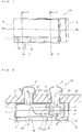
- Fig. 2 is a horizontal sectional view of the ventilation device 100 taken along the dotted line X of Fig. 1 .
- Fig. 3 is a vertical sectional view of the ventilation device 100 taken along the dotted line Y of Fig. 1 .
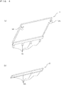
- Fig. 4(a) is a view of a panel 2 illustrated in Fig. 1 when viewed from a back surface side thereof.
- Fig. 4(b) is a view of an airflow-direction changeable component 3 illustrated in Fig. 1 when viewed from a back surface side thereof.
- the arrows illustrated in Figs. 1 and 2 indicate a flow of air.
- Fig. 1 illustrates a lower part of the ventilation device 100 in transparent view.
- the ventilation device 100 according to Embodiment 1 is improved in its airflow direction louver and supply air outlet to suppress degradation of user's comfort and design of the product.
- the size relationship of the constituent members illustrated in the following figures including Fig. 1 may differ from the actual size relationship.
- the same or corresponding parts are represented by the same reference symbols, and the same applies hereinafter.
- the forms of the constituent elements described herein are only examples and the present invention is not limited to the forms thus described.
- the ventilation device 100 is capable of taking air from the inside of an air-conditioned space (such as a room, a building, or a warehouse) to discharge the air to the outside of the air-conditioned space, and is also capable of taking air from the outside of the air-conditioned space to supply the air to the inside of the air-conditioned space.
- an air-conditioned space such as a room, a building, or a warehouse
- a room is described exemplarily as the air-conditioned space.
- “outdoor air” corresponds to supply air, which is supplied from the ventilation device 100 to the indoors
- “indoor air” corresponds to "exhaust air", which is discharged from the ventilation device 100 to the outdoors.
- the ventilation device 100 includes a main body 1 on which various devices are mounted, the panel 2 arranged on a front surface side of the main body 1, the airflow-direction changeable component 3 mounted below the panel 2 on the front surface side of the main body 1, an air supply pipe 13 connected to a back surface side of the main body 1 for taking the outdoor air, an air exhaust pipe 14 connected to the back surface side of the main body 1 for discharging the indoor air, a heat exchanger 11 for exchanging heat between the outdoor air and the indoor air thus taken, an air supply fan 8 for taking the outdoor air, and an air exhaustion fan 9 for taking the indoor air.
- the ventilation device 100 is mounted on a wall 50 having an opening port 13A communicating the indoors and the outdoors with each other, in which the air supply pipe 13 is arranged, and an opening port 14A communicating the indoors and the outdoors with each other, in which the air exhaust pipe 14 is arranged.
- the main body 1 is formed into a substantially rectangular parallelepiped shape to define an outer shell. At least the air supply fan 8 for taking the outdoor air, the air exhaustion fan 9 for taking the indoor air, and the heat exchanger 11 for exchanging heat between the outdoor air and the indoor air introduced into the main body 1 are mounted on the main body 1.
- the panel 2 is arranged on the front surface side of the main body 1 to define the front surface of the ventilation device 100.
- the airflow-direction changeable component 3 is arranged below the panel 2.
- the air supply pipe 13 communicating the outdoors and the main body 1 with each other is connected to the back surface side of the main body 1. Further, the air exhaust pipe 14 communicating the outdoors and the main body 1 with each other is connected to the back surface side of the main body 1 at a position on the left of the air supply pipe 13 in front view.
- An air inlet 1A through which the indoor air is sucked and a main-body air outlet 1E through which the air is discharged after the heat is exchanged by the heat exchanger 11 are formed on the front surface side of the main body 1.
- the main-body air outlet 1E and the air inlet 1A are formed at positions opposed to the back surface side of the panel 2.
- a bellmouth 1D is formed at the air inlet 1A to adjust the flow of the air sucked from the indoors into the main body 1, to thereby suppress generation of noise.
- the degradation of the user's comfort can be suppressed.
- a supply air port 1B connected to the air supply pipe 13 and an exhaust air port 1C connected to the air exhaust pipe 14 are formed on the back surface side of the main body 1.
- a partition plate 30 is arranged upright inside the main body 1 to prevent the outdoor air and the indoor air supplied into the main body 1 from being mixed with each other.
- a front surface side of the partition plate 30 defines an air passage through which the indoor air supplied into the main body 1 is caused to flow, whereas a back surface side of the partition plate 30 defines an air passage through which the outdoor air supplied into the main body 1 is caused to flow.
- a left edge portion side of the partition plate 30 in front view is arranged on a right surface side of the heat exchanger11.
- the panel 2 is arranged on the front side of the main body 1 to define a part of the front surface of the ventilation device 100.
- the panel 2 is a flat plate member having a substantially rectangular flat shape in front view. Under a state in which the main body 1 is mounted on the wall 50, the panel 2 is arranged in parallel to a vertical direction. Further, as illustrated in Fig. 4(b) , holding portions 70 for holding the airflow-direction changeable component 3 in a freely rotatable manner are formed on a lower edge side of the panel 2.
- the panel 2 defines an air outlet 7 by the back surface side of the panel 2 and the front surface side of the main body 1. That is, the airflow-direction changeable component 3 is held by the holding portions 70 under a state in which a "predetermined interval" is secured between the back surface of the panel 2 and the front surface of the main body 1. Further, the air outlet 7 is formed between the "lower edge side of the back surface of the panel 2" and the “lower side of the front surface of the main body 1" (see Figs. 6 and 7 ).
- the mounting accuracy of the airflow-direction changeable component 3 is determined depending on fluctuations of molded products of the main body 1, the panel 2, and the airflow-direction changeable component 3. That is, the mounting accuracy of the airflow-direction changeable component 3 is reduced by an amount corresponding to the molding fluctuations of a total of three members, namely, the main body 1, the panel 2, and the airflow-direction changeable component 3.
- members corresponding to the holding portions 70 may be formed on the main body 1 so that the main body 1 holds the airflow-direction changeable component 3, but the mounting accuracy of the airflow-direction changeable component 3 is reduced in this case. Therefore, it is preferred that the airflow-direction changeable component 3 be mounted on the panel 2 as in Embodiment 1.
- Connecting portions 2A to be connected to the main body 1 are formed at upper parts of the panel 2 on the back surface side. With the connecting portions 2A, the panel 2 is held on the front surface side of the main body 1.
- the connecting portions 2A are rotatable about connection points between the connecting portions 2A and the main body 1. That is, the panel 2 is lifted upward through the rotation of the connecting portions 2A, and hence the front surface side of the main body 1, the air exhaustion fan 9, and the like are exposed, thereby being capable of carrying out, for example, cleaning.
- the airflow-direction changeable component 3 is capable of changing the direction of air to be blown out through the air outlet 7.
- the airflow-direction changeable component 3 is arranged below the panel 2 on the front surface side of the main body 1 in a rotatable manner.
- the airflow-direction changeable component 3 is a flat plate member having, for example, a substantially rectangular flat shape in front view.
- FIG. 4(b) on the back surface side of the airflow-direction changeable component 3, four pivot portions 3A for connecting the airflow-direction changeable component 3 and the main body 1 to each other are formed along a width direction in front view of the main body 1. With the pivot portions 3A, the airflow-direction changeable component 3 is held on the front surface side of the main body 1 in a freely rotatable manner.
- the airflow-direction changeable component 3 is described later in detail with reference to Figs. 5 to 7 .
- the air supply pipe 13 is arranged in the opening port 13A of the wall 50 to connect the main body 1 and the outdoors to each other.
- One end side of the air supply pipe 13 is connected to the supply air port 1B of the main body 1, whereas the other end side of the air supply pipe 13 is arranged on the outdoor side.
- an air supply hood 12 is arranged on the other end side of the air supply pipe 13 to prevent, for example, entry of rainwater from the other end side of the air supply pipe 13 to the indoor side even in the event of significant rainstorm.
- the air exhaust pipe 14 is arranged in the opening port 14A of the wall 50 to connect the main body 1 and the outdoors to each other.
- One end side of the air exhaust pipe 14 is connected to the exhaust air port 1C of the main body 1, whereas the other end side of the air exhaust pipe 14 is arranged on the outdoor side.
- an air exhaust hood 15 is arranged on the other end side of the air exhaust pipe 14 to prevent, for example, entry of rainwater from the other end side of the air exhaust pipe 14 to the indoor side even in the event of significant rainstorm.
- the air supply hood 12 is mounted on a surface of the wall 50 on the outdoor side to prevent, for example, entry of rainwater from the other end side of the air supply pipe 13 to the indoor side even in the event of significant rainstorm.
- a part of the air supply hood 12 on a side mounted on the wall 50 communicates with the air supply pipe 13.
- the air exhaust hood 15 is mounted on the surface of the wall 50 on the outdoor side to prevent, for example, entry of rainwater from the other end side of the air exhaust pipe 14 to the indoor side even in the event of significant rainstorm.
- a part of the air exhaust hood 15 on a side mounted on the wall 50 communicates with the air exhaust pipe 14.
- the heat exchanger 11 is configured to exchange heat between the outdoor air and the indoor air introduced into the main body 1. That is, the heat exchanger 11 has a function of recovering an amount of heat of the exhaust air with the supply air. Note that, the heat exchanger 11 is configured to prevent the outdoor air and the indoor air flowing into the heat exchanger 11 from being mixed with each other. That is, in the heat exchanger 11, a supply air flow passage through which the outdoor air flowing into the heat exchanger 11 is caused to flow and an exhaust air flow passage through which the indoor air flowing into the heat exchanger 11 is caused to flow are formed in contact with each other in a heat exchangeable manner, and the supply air flow passage and the exhaust air flow passage are separated from each other. In front view, the heat exchanger 11 is arranged on the left of the air supply fan 8 and the air exhaustion fan 9 as illustrated in Fig. 2 .
- An inflow port 11A through which the outdoor air is caused to flow into the heat exchanger 11 and an outflow port 11B through which the air flowing into the heat exchanger 11 through the inflow port 11A is discharged after the heat is exchanged are formed in the heat exchanger 11. Further, an inflow port 11C through which the indoor air is caused to flow into the heat exchanger 11 and an outflow port 11D through which the air flowing into the heat exchanger 11 through the inflow port 11C is discharged after the heat is exchanged are formed in the heat exchanger 11.
- the outdoor air is supplied by the air supply fan 8 to the inflow port 11A. Further, the air blown out through the outflow port 11B is discharged from the main body 1 through the main-body air outlet 1E.
- the indoor air is supplied by the air exhaustion fan 9 to the inflow port 11C. Further, the air blown out through the outflow port 11D is discharged from the main body 1 through the exhaust air port 1C.
- the air supply fan 8 includes a rotatable fan 8A and a motor 10 for rotating the fan 8A.
- the air supply fan 8 is configured to rotate by rotation of the motor 10 that is transmitted to the fan 8A via a shaft 10A, to thereby take the outdoor air into the main body 1 and discharge the outdoor air from the main body 1.
- the air exhaustion fan 9 includes a rotatable fan 9A and the motor 10 for rotating the fan 9A.
- the air exhaustion fan 9 is configured to rotate through the rotation of the motor 10 that is transmitted to the fan 9A via a shaft 10B, to thereby take the indoor air into the main body 1 and discharge the indoor air from the main body 1.
- the fans 8A and 9A are, for example, sirocco fans, which are connected to the shafts 10A and 10B, respectively.
- the shafts 10A and 10B are connected to the fans 8A and 9A, respectively, so that the fans 8A and 9A are rotated through the transmission of the rotation of the motor 10 thereto.
- the motor 10 includes the shaft 10A arranged on the air passage side through which the supply air is caused to flow, and the shaft 10B arranged on the air passage side through which the exhaust air is caused to flow. Further, the motor 10 is arranged across the partition plate 30 on both of the air passage side through which the supply air is caused to flow and the air passage side through which the exhaust air is caused to flow.
- An air-passage closing wall 40 is capable of reducing air to be blown out through a ventilation-device vertical plane air outlet 41 or a ventilation-device horizontal plane air outlet 42 toward a side surface of the main body in a horizontal direction.
- the air-passage closing wall 40 is mounted at a side surface portion of the ventilation-device vertical plane air outlet 41 below the panel 2 on the front surface side of the main body 1.
- the air-passage closing wall 40 is described later in detail with reference to Figs. 5 to 7 .
- the ventilation-device vertical plane air outlet 41 is defined to open toward the front of the ventilation device 100 when the airflow-direction changeable component 3 is at a position where the airflow-direction changeable component 3 is in parallel to the horizontal direction of the ventilation device (first position). That is, the ventilation-device vertical plane air outlet 41 is defined to blow out through the air outlet 7 toward the front of the ventilation device 100.
- the ventilation-device horizontal plane air outlet 42 is defined to open in a direction toward the bottom of the ventilation device 100 when the airflow-direction changeable component 3 is at a position where the airflow-direction changeable component 3 is brought into a state of being parallel to the vertical direction of the ventilation device (second position). That is, the ventilation-device horizontal plane air outlet 42 is defined to blow out the air through the air outlet 7 toward the bottom of the ventilation device 100.
- Fig. 5 is a perspective view of a state in which the airflow-direction changeable component 3 of the ventilation device 100 illustrated in Fig. 1 is moved to take a posture substantially parallel to the horizontal plane.
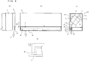
- Figs. 6 are explanatory views illustrating a state in which the airflow-direction changeable component 3 is at the second position.
- Figs. 7 are explanatory views illustrating a state in which the airflow-direction changeable component 3 is at the first position. Note that, the arrows illustrated in Figs. 5 to 7 indicate a flow of air. Referring to Figs. 5 to 7 , the airflow-direction changeable component 3 is described in detail.
- Fig. 6(a) is a side view of the state in which the airflow-direction changeable component 3 of the ventilation device 100 is at the second position.
- Fig. 6(b) is a front view of the state in which the airflow-direction changeable component 3 of the ventilation device 100 is at the second position.
- Fig. 6(c) is a vertical sectional view taken along the dotted line V of Fig. 1 , for illustrating the state in which the airflow-direction changeable component 3 of the ventilation device 100 is at the second position.
- Fig. 6(d) is a horizontal sectional view taken along the dotted line Z of Fig. 6(c) .
- Fig. 7(a) is a side view of the state in which the airflow-direction changeable component 3 of the ventilation device 100 is at the first position.
- Fig. 7(b) is a front view of the state in which the airflow-direction changeable component 3 of the ventilation device 100 is at the first position.
- Fig. 7(c) is a vertical sectional view taken along the dotted line W of Fig. 5 , for illustrating the state in which the airflow-direction changeable component 3 of the ventilation device 100 is at the first position.
- the airflow-direction changeable component 3 is arranged below the panel 2 on the front surface side of the main body 1 in a rotatable manner, and is capable of changing the direction of the air to be blown out through the air outlet 7.
- the airflow-direction changeable component 3 is a plate-like member having a substantially rectangular flat shape in front view.
- a heat insulating member 31 is arranged on the back surface side of the airflow-direction changeable component 3. With the heat insulating member 31, dew condensation or the like on the airflow-direction changeable component 3 can be suppressed, thereby being capable of suppressing the degradation of the user's comfort that may be caused by the drip of dew water in the indoors or the like.
- the four pivot portions 3A for connecting the airflow-direction changeable component 3 and the main body 1 to each other are formed along the width direction in front view of the main body 1.
- the pivot portions 3A of the airflow-direction changeable component 3 are held by the holding portions 70 of the panel 2 in a freely rotatable manner.
- the pivot portions 3A are formed on the back surface side of the airflow-direction changeable component 3 in a protruding manner. Further, the pivot portions 3A are rotatable about their rotational axes parallel to the horizontal plane.
- the airflow-direction changeable component 3 is movable to the following two positions through its rotation. That is, the airflow-direction changeable component 3 is movable to the position where the airflow-direction changeable component 3 is brought into a state of being parallel to the vertical direction (second position) (see Figs. 1 and 6 ). Further, the airflow-direction changeable component 3 is movable to the position where the airflow-direction changeable component 3 is brought into a state of being parallel to the horizontal direction (first position) (see Figs. 5 and 7 ).
- the airflow-direction changeable component 3 When the airflow-direction changeable component 3 is moved to the position where the airflow-direction changeable component 3 is brought into a state of being parallel to the vertical direction, the airflow-direction changeable component 3 is positioned on the front side relative to the pivot portions 3A. Further, when the airflow-direction changeable component 3 is moved to the position where the airflow-direction changeable component 3 is brought into a state of being parallel to the vertical direction, the air is discharged through the air outlet 7 downward to the indoors as illustrated in Figs. 6 .
- the airflow-direction changeable component 3 When the airflow-direction changeable component 3 is moved to the position where the airflow-direction changeable component 3 is brought into a state of being parallel to the horizontal direction, the airflow-direction changeable component 3 is positioned on the lower side relative to the pivot portions 3A. When the airflow-direction changeable component 3 is moved to the position where the airflow-direction changeable component 3 is brought into a state of being parallel to the horizontal direction, the air is discharged through the air outlet 7 forward to the indoors as illustrated in Figs. 7 .
- the surface of the airflow-direction changeable component 3 on the front side under the state in which the airflow-direction changeable component 3 is arranged at the position where the airflow-direction changeable component 3 is brought into a state of being parallel to the vertical direction is defined as "decorative surface 18".
- the decorative surface 18 is parallel to a front surface side of the panel 2, and one edge portion of the airflow-direction changeable component 3 is brought into contact with the lower edge of the panel 2 (see Figs. 1 and 6 ). That is, the front surface of the panel 2 and the decorative surface 18 of the airflow-direction changeable component 3 are positioned substantially flush with each other, thereby being capable of improving the design of the ventilation device 100.
- the decorative surface 18 of the airflow-direction changeable component 3 may be positioned on a front or back side relative to the front surface of the panel 2. As described above, even when the panel 2 and the airflow-direction changeable component 3 have level difference therebetween in vertical sectional view thereof, the decorative surface 18 of the airflow-direction changeable component 3 is positioned "on an extension of the panel 2", thereby being capable of enhancing the design of the ventilation device 100.
- the description “on an extension of the panel 2" encompasses the structure in which "the decorative surface 18 of the airflow-direction changeable component 3 is positioned on a front or back side relative to the front surface of the panel 2".
- one edge portion of the airflow-direction changeable component 3 may be positioned along the lower edge of the panel 2 via a predetermined clearance therebetween.
- the decorative surface 18 is parallel to a bottom surface of the main body 1, and the other edge portion of the airflow-direction changeable component 3 is brought into contact with the bottom surface of the main body 1 (see Figs. 5 and 7 ). That is, the bottom surface of the main body 1 and the decorative surface 18 of the airflow-direction changeable component 3 are positioned substantially flush with each other, thereby being capable of enhancing the design of the ventilation device 100.
- the decorative surface 18 of the airflow-direction changeable component 3 may be positioned on an upper or lower side relative to the bottom surface of the main body 1. As described above, even when the main body 1 and the airflow-direction changeable component 3 have level difference therebetween in vertical sectional view thereof, the decorative surface 18 of the airflow-direction changeable component 3 is positioned "on an extension of the bottom surface of the main body 1", thereby being capable of enhancing the design of the ventilation device 100.
- the description “on an extension of the bottom surface of the main body 1" encompasses the structure in which "the decorative surface 18 of the airflow-direction changeable component 3 is positioned on an upper or lower side relative to the bottom surface of the main body 1".
- the other edge portion of the airflow-direction changeable component 3 may be positioned along the lower edge of the panel 2 via a predetermined clearance therebetween.
- Embodiment 1 is directed to the example in which the "four" pivot portions 3A are formed along the width direction of the airflow-direction changeable component 3 in front view of the main body 1, but the number of pivot portions 3A is not limited to "four". Further, it is only necessary to form as many holding portions 70 as the pivot portions 3A on the panel 2.
- pivot portions 3A may be configured to rotate manually by the user or the like, or to rotate electrically by, for example, a drive motor.
- the air-passage closing wall 40 is capable of changing the direction of the air to be blown out through the air outlet 7 to a direction through the ventilation-device vertical plane air outlet 41 or the ventilation-device horizontal plane air outlet 42.
- the air-passage closing wall 40 is a wall arranged at a predetermined interval (for example, about 1 mm to 20 mm) from the side surface portion of the ventilation-device vertical plane air outlet 41 below the panel 2 on the front surface side of the main body 1, or at a predetermined interval (for example, about 1 mm to 20 mm) from a side surface portion of the ventilation device 100.
- the airflow-direction changeable component 3 When the airflow-direction changeable component 3 is at the position where the airflow-direction changeable component 3 is brought into a state of being parallel to the horizontal direction of the ventilation device (first position), the back surface of the airflow-direction changeable component 3 and a flat bottom surface portion of the air-passage closing wall 40 are brought into contact with each other. As a result, a wall is defined by the air-passage closing wall 40 on the left or right of the ventilation device 100 in the horizontal direction, to thereby close the flow passage of air flowing in the horizontal direction. In addition, a wall is defined by the airflow-direction changeable component 3 on the bottom surface portion, to thereby define the ventilation-device vertical plane air outlet 41 (see Figs. 5 and 7 ).
- the airflow-direction changeable component 3 When the airflow-direction changeable component 3 is at the position where the airflow-direction changeable component 3 is brought into a state of being parallel to the vertical direction of the ventilation device (second position), the back surface of the airflow-direction changeable component 3 and a front surface of the air-passage closing wall 40 are brought into contact with each other. As a result, a wall is defined by the air-passage closing wall 40 on the left or right of the ventilation device 100 in the horizontal direction, to thereby close the flow passage of air flowing in the horizontal direction. In addition, a wall is defined by the airflow-direction changeable component 3 on the front surface side, to thereby define the ventilation-device horizontal plane air outlet 42 (see Figs. 1 and 6 ).
- Embodiment 1 is directed to the example in which the air-passage closing wall 40 is a wall arranged at a predetermined interval from the side surface portion of the ventilation-device vertical plane air outlet 41 below the panel 2 on the front surface side of the main body 1, or at a predetermined interval from the side surface portion of the ventilation device 100.
- the air-passage closing wall 40 may be arranged at both of the side surface portion of the ventilation-device vertical plane air outlet 41 and the side surface portion of the ventilation device 100.
- the air-passage closing wall 40 may be fixed in a freely removable manner, or may be fixed in a non-removable manner.
- Embodiment 1 is described by taking as an example the state in which the air-passage closing wall 40 is mounted on the left of the drawing sheet, but the air-passage closing wall 40 may be mounted on the right of the drawing sheet.
- the size, thickness, shape, constituent material, and the like of the air-passage closing wall 40 are not particularly limited as long as the wall is defined on the left or right of the ventilation device 100 in the horizontal direction.
- the outdoor air is taken from the air supply hood 12 into the main body 1 through the air supply pipe 13.
- the air taken into the main body 1 is caused to flow into the heat exchanger 11 through the air supply fan 8.
- the air flowing into the heat exchanger 11 is discharged from the heat exchanger 11 after heat is exchanged between the air and the indoor air flowing into the heat exchanger 11.
- the air discharged from the heat exchanger 11 is blown out from the air outlet 7 through the main-body air outlet 1E, and then discharged from the ventilation device 100 with the airflow direction adjusted to the vertical direction or the horizontal direction by the action of the airflow-direction changeable component 3.
- the air discharged with the airflow direction adjusted to the vertical direction or the horizontal direction is discharged from the ventilation device 100 under a state in which the air flowing toward the side surface of the main body 1 in the horizontal direction is reduced by the action of the air-passage closing wall 40.
- the indoor air is taken into the main body 1 through the air inlet 1A.
- the indoor air taken into the main body 1 is caused to flow into the heat exchanger 11 through the air exhaustion fan 9.
- the air flowing into the heat exchanger 11 is discharged from the heat exchanger 11 after heat is exchanged between the air and the outdoor air flowing into the heat exchanger 11. Then, the air discharged from the heat exchanger 11 is discharged to the outdoors through the air exhaust pipe 14 and the air exhaust hood 15.
- the ventilation device 100 according to Embodiment 1 includes the airflow-direction changeable component 3 capable of adjusting whether to blow out the air to be discharged from the main body 1 in the vertically downward direction or the horizontal direction.
- the airflow-direction changeable component 3 capable of adjusting whether to blow out the air to be discharged from the main body 1 in the vertically downward direction or the horizontal direction.
- the airflow-direction changeable component 3 is capable of adjusting the air to be blown out in the horizontal direction. Thus, it is possible to suppress undesirable cooling in the user's feet caused by a cold draft.
- the direction of air to be blown out is adjusted by the airflow-direction changeable component 3 instead of the panel 2, thereby suppressing a situation where dust or the like carried by the air that is taken from the outdoors adheres to the panel 2.
- the airflow-direction changeable component 3 instead of the panel 2
- the ventilation device 100 according to Embodiment 1 includes the air-passage closing wall 40 capable of reducing air to be blown out from the main body 1 in the horizontal direction.
- the air-passage closing wall 40 capable of reducing air to be blown out from the main body 1 in the horizontal direction.
- Fig. 8 is a view of a model showing a state in which the ventilation device 100 is installed in a simple indoor space.
- Fig. 9 is a view of a model schematically showing the ventilation device 100.
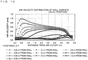
- Fig. 10 is a graph showing analysis results of an air velocity distribution at a wall surface in the models shown in Figs. 8 and 9 . Referring to Figs. 8 to 10 , description is given of the air velocity distribution at the wall surface in the indoors where the ventilation device 100 is installed. Note that, in Fig. 10 , the horizontal axis represents a distance (m) from the air outlet (ventilation-device vertical plane air outlet 41 or ventilation-device horizontal plane air outlet 42), and the vertical axis represents an air velocity (m/s).
- Fig. 10 shows analysis results of the air velocity distribution at the wall surface in a case where the ventilation device 100 is installed at a distance of 0.1 m from an indoor ceiling and a distance D from the wall surface (0.02 m, 0.04 m, 0.06 m, 0.08 m, 0.1 m, 0.2 m, 0.4 m, 0.6 m, 0.8 m, and 1.0 m) as shown in Fig. 8 and air is blown out through the ventilation-device vertical plane air outlet 41 or the ventilation-device horizontal plane air outlet 42 at an airflow rate of 100 m 3 /h.
- the wall or ceiling When the airflow thus blown out is brought into contact with the wall or ceiling, the wall or ceiling may be soiled due to adhesion of dust or the like. Further, it is considered that the soil is less liable to adhere as the air velocity is lower when the airflow is brought into contact with an object. Therefore, when an air velocity of 0.8 m/s is defined as a reference, it is found based on the analysis results shown in Fig. 10 that the cause of soiling of the wall can be reduced and the degree of freedom of installation can be increased by keeping the ventilation device 100 away from the wall surface at a distance of 0.04 m (dimension D) or more. It is preferable to determine the installation position of the ventilation device 100 in consideration of the fact described above. Note that, the numerical values and dimensions shown in Figs. 8 and 9 are examples for better understanding of the air velocity distribution of the ventilation device 100, and the present invention is not limited to those numerical values and dimensions.
- the ventilation device 100 according to Embodiment 1 includes the air-passage closing wall 40 capable of reducing air to be discharged from the main body 1 and blown out in the horizontal direction.
- the air-passage closing wall 40 serves as a blindfold for the complex internal components of the ventilation device 100, thereby improving the design.
Landscapes
- Engineering & Computer Science (AREA)
- Chemical & Material Sciences (AREA)
- Combustion & Propulsion (AREA)
- Mechanical Engineering (AREA)
- General Engineering & Computer Science (AREA)
- Air-Flow Control Members (AREA)
Description
- The present invention relates to a ventilation device.
- As a related-art ventilation device, there is proposed a wall-mount heat-exchange ventilation device in which a heat exchanger is mounted on a main body and the main body is mounted on a wall or the like to communicate indoors and outdoors with each other (see, for example, Patent Literature 1). The ventilation device disclosed in
Patent Literature 1 is configured to exchange heat between air sucked from the outdoors and air sucked from the indoors, and then blow out the air in a predetermined direction through an indoor air outlet. - Patent Literature 1: Japanese Unexamined Patent Application Publication No.
Hei 9-273793 Fig. 2 ) - In the technology disclosed in
Patent Literature 1, an airflow direction louver or the like is not arranged so that the direction of the air to be blown out through the indoor air outlet of the ventilation device is determined when the device is installed indoors. The air is caused to flow in a direction toward a floor (in a downward direction), and toward a wall parallel to a side surface of the main body (in a horizontal direction). Therefore, when a wall exists at a destination of the air flowing in the direction toward the wall parallel to the side surface of the main body (in the horizontal direction), the air thus blown out continuously impinges on the wall, which may be a cause of soiling of the wall due to dust or the like carried by the air that is taken from the outdoors. - Further, in the technology disclosed in
Patent Literature 1, in order to reduce the soiling of the wall, a distance equal to or larger than predetermined spacing (about 0.083 m) needs to be secured from the wall parallel to the side surface of the main body at the time of mounting the main body so that air does not impinge on the wall. Therefore, the mounting position may be limited, and the degree of freedom of installation and the design may be degraded. - The present invention has been made to solve at least one of the problems described above, and it is therefore an object of the present invention to provide a ventilation device capable of suppressing degradation of user's comfort and design.
- The present invention provides a ventilation device as set forth in
claim 1. - The ventilation device according to the one embodiment of the present invention includes the air-passage closing wall for changing the direction of air parallel to the side surface of the main body, which is blown out through the air outlet, thereby being capable of avoiding the soiling of the wall that may be caused when the dust carried by the outdoor air continuously impinges on the wall. Thus, it is possible to suppress the degradation of the user's comfort and the design.
-
- [
Fig. 1] Fig. 1 is a perspective view of a ventilation device according toEmbodiment 1. - [
Fig. 2] Fig. 2 is a horizontal sectional view of the ventilation device taken along the dotted line X ofFig. 1 . - [
Fig. 3] Fig. 3 is a vertical sectional view of the ventilation device taken along the dotted line Y ofFig. 1 . - [
Figs. 4] Fig. 4(a) is a view of a panel illustrated inFig. 1 when viewed from a back surface side thereof, andFig. 4(b) is a view of an airflow-direction changeable component illustrated inFig. 1 when viewed from a back surface side thereof. - [
Fig. 5] Fig. 5 is a perspective view of a state in which the airflow-direction changeable component of the ventilation device illustrated inFig. 1 is moved to take a posture parallel to a horizontal plane. - [
Figs. 6] Figs. 6 are explanatory views illustrating a state in which the airflow-direction changeable component of the ventilation device according toEmbodiment 1 is at a second position. - [
Figs. 7] Figs. 7 are explanatory views illustrating a state in which the airflow-direction changeable component of the ventilation device according toEmbodiment 1 is at a first position. - [
Fig. 8] Fig. 8 is a view of a model showing a state in which the ventilation device according to Embodiment 1 is installed in a simple indoor space. - [
Fig. 9] Fig. 9 is a view of a model schematically showing the ventilation device according toEmbodiment 1. - [
Fig. 10] Fig. 10 is a graph showing analysis results of an air velocity distribution at a wall surface in the models shown inFigs. 8 and 9 . - Now, an embodiment of the present invention is described with reference to the drawings.
-
Fig. 1 is a perspective view of aventilation device 100 according toEmbodiment 1.Fig. 2 is a horizontal sectional view of theventilation device 100 taken along the dotted line X ofFig. 1 .Fig. 3 is a vertical sectional view of theventilation device 100 taken along the dotted line Y ofFig. 1 .Fig. 4(a) is a view of apanel 2 illustrated inFig. 1 when viewed from a back surface side thereof.Fig. 4(b) is a view of an airflow-directionchangeable component 3 illustrated inFig. 1 when viewed from a back surface side thereof. Note that, the arrows illustrated inFigs. 1 and 2 indicate a flow of air. Further,Fig. 1 illustrates a lower part of theventilation device 100 in transparent view. - The
ventilation device 100 according toEmbodiment 1 is improved in its airflow direction louver and supply air outlet to suppress degradation of user's comfort and design of the product. Note that, the size relationship of the constituent members illustrated in the following figures includingFig. 1 may differ from the actual size relationship. Further, in the following figures includingFig. 1 , the same or corresponding parts are represented by the same reference symbols, and the same applies hereinafter. Further, the forms of the constituent elements described herein are only examples and the present invention is not limited to the forms thus described. - The
ventilation device 100 is capable of taking air from the inside of an air-conditioned space (such as a room, a building, or a warehouse) to discharge the air to the outside of the air-conditioned space, and is also capable of taking air from the outside of the air-conditioned space to supply the air to the inside of the air-conditioned space. In the following, a room is described exemplarily as the air-conditioned space. Further, "outdoor air" corresponds to supply air, which is supplied from theventilation device 100 to the indoors, whereas "indoor air" corresponds to "exhaust air", which is discharged from theventilation device 100 to the outdoors. - The
ventilation device 100 includes amain body 1 on which various devices are mounted, thepanel 2 arranged on a front surface side of themain body 1, the airflow-directionchangeable component 3 mounted below thepanel 2 on the front surface side of themain body 1, anair supply pipe 13 connected to a back surface side of themain body 1 for taking the outdoor air, anair exhaust pipe 14 connected to the back surface side of themain body 1 for discharging the indoor air, aheat exchanger 11 for exchanging heat between the outdoor air and the indoor air thus taken, anair supply fan 8 for taking the outdoor air, and anair exhaustion fan 9 for taking the indoor air. - Further, the
ventilation device 100 is mounted on awall 50 having anopening port 13A communicating the indoors and the outdoors with each other, in which theair supply pipe 13 is arranged, and anopening port 14A communicating the indoors and the outdoors with each other, in which theair exhaust pipe 14 is arranged. - The
main body 1 is formed into a substantially rectangular parallelepiped shape to define an outer shell. At least theair supply fan 8 for taking the outdoor air, theair exhaustion fan 9 for taking the indoor air, and theheat exchanger 11 for exchanging heat between the outdoor air and the indoor air introduced into themain body 1 are mounted on themain body 1. - The
panel 2 is arranged on the front surface side of themain body 1 to define the front surface of theventilation device 100. The airflow-directionchangeable component 3 is arranged below thepanel 2. - The
air supply pipe 13 communicating the outdoors and themain body 1 with each other is connected to the back surface side of themain body 1. Further, theair exhaust pipe 14 communicating the outdoors and themain body 1 with each other is connected to the back surface side of themain body 1 at a position on the left of theair supply pipe 13 in front view. - An
air inlet 1A through which the indoor air is sucked and a main-body air outlet 1E through which the air is discharged after the heat is exchanged by theheat exchanger 11 are formed on the front surface side of themain body 1. The main-body air outlet 1E and theair inlet 1A are formed at positions opposed to the back surface side of thepanel 2. Note that, abellmouth 1D is formed at theair inlet 1A to adjust the flow of the air sucked from the indoors into themain body 1, to thereby suppress generation of noise. Thus, the degradation of the user's comfort can be suppressed. - A
supply air port 1B connected to theair supply pipe 13 and anexhaust air port 1C connected to theair exhaust pipe 14 are formed on the back surface side of themain body 1. - A
partition plate 30 is arranged upright inside themain body 1 to prevent the outdoor air and the indoor air supplied into themain body 1 from being mixed with each other. A front surface side of thepartition plate 30 defines an air passage through which the indoor air supplied into themain body 1 is caused to flow, whereas a back surface side of thepartition plate 30 defines an air passage through which the outdoor air supplied into themain body 1 is caused to flow. A left edge portion side of thepartition plate 30 in front view is arranged on a right surface side of the heat exchanger11. - The
panel 2 is arranged on the front side of themain body 1 to define a part of the front surface of theventilation device 100. Thepanel 2 is a flat plate member having a substantially rectangular flat shape in front view. Under a state in which themain body 1 is mounted on thewall 50, thepanel 2 is arranged in parallel to a vertical direction. Further, as illustrated inFig. 4(b) , holdingportions 70 for holding the airflow-directionchangeable component 3 in a freely rotatable manner are formed on a lower edge side of thepanel 2. - The
panel 2 defines anair outlet 7 by the back surface side of thepanel 2 and the front surface side of themain body 1. That is, the airflow-directionchangeable component 3 is held by the holdingportions 70 under a state in which a "predetermined interval" is secured between the back surface of thepanel 2 and the front surface of themain body 1. Further, theair outlet 7 is formed between the "lower edge side of the back surface of thepanel 2" and the "lower side of the front surface of themain body 1" (seeFigs. 6 and7 ). - When the airflow-direction
changeable component 3 is mounted on, for example, themain body 1, the mounting accuracy of the airflow-directionchangeable component 3 is determined depending on fluctuations of molded products of themain body 1, thepanel 2, and the airflow-directionchangeable component 3. That is, the mounting accuracy of the airflow-directionchangeable component 3 is reduced by an amount corresponding to the molding fluctuations of a total of three members, namely, themain body 1, thepanel 2, and the airflow-directionchangeable component 3. - Thus, for example, members corresponding to the holding
portions 70 may be formed on themain body 1 so that themain body 1 holds the airflow-directionchangeable component 3, but the mounting accuracy of the airflow-directionchangeable component 3 is reduced in this case. Therefore, it is preferred that the airflow-directionchangeable component 3 be mounted on thepanel 2 as inEmbodiment 1. - Connecting
portions 2A to be connected to themain body 1 are formed at upper parts of thepanel 2 on the back surface side. With the connectingportions 2A, thepanel 2 is held on the front surface side of themain body 1. - The connecting
portions 2A are rotatable about connection points between the connectingportions 2A and themain body 1. That is, thepanel 2 is lifted upward through the rotation of the connectingportions 2A, and hence the front surface side of themain body 1, theair exhaustion fan 9, and the like are exposed, thereby being capable of carrying out, for example, cleaning. - The airflow-direction
changeable component 3 is capable of changing the direction of air to be blown out through theair outlet 7. The airflow-directionchangeable component 3 is arranged below thepanel 2 on the front surface side of themain body 1 in a rotatable manner. The airflow-directionchangeable component 3 is a flat plate member having, for example, a substantially rectangular flat shape in front view. - As illustrated in
Fig. 4(b) , on the back surface side of the airflow-directionchangeable component 3, fourpivot portions 3A for connecting the airflow-directionchangeable component 3 and themain body 1 to each other are formed along a width direction in front view of themain body 1. With thepivot portions 3A, the airflow-directionchangeable component 3 is held on the front surface side of themain body 1 in a freely rotatable manner. The airflow-directionchangeable component 3 is described later in detail with reference toFigs. 5 to 7 . - The
air supply pipe 13 is arranged in theopening port 13A of thewall 50 to connect themain body 1 and the outdoors to each other. One end side of theair supply pipe 13 is connected to thesupply air port 1B of themain body 1, whereas the other end side of theair supply pipe 13 is arranged on the outdoor side. Note that, anair supply hood 12 is arranged on the other end side of theair supply pipe 13 to prevent, for example, entry of rainwater from the other end side of theair supply pipe 13 to the indoor side even in the event of significant rainstorm. - The
air exhaust pipe 14 is arranged in theopening port 14A of thewall 50 to connect themain body 1 and the outdoors to each other. One end side of theair exhaust pipe 14 is connected to theexhaust air port 1C of themain body 1, whereas the other end side of theair exhaust pipe 14 is arranged on the outdoor side. Note that, similarly to the other end side of theair supply pipe 13, anair exhaust hood 15 is arranged on the other end side of theair exhaust pipe 14 to prevent, for example, entry of rainwater from the other end side of theair exhaust pipe 14 to the indoor side even in the event of significant rainstorm. - The
air supply hood 12 is mounted on a surface of thewall 50 on the outdoor side to prevent, for example, entry of rainwater from the other end side of theair supply pipe 13 to the indoor side even in the event of significant rainstorm. A part of theair supply hood 12 on a side mounted on thewall 50 communicates with theair supply pipe 13. - The
air exhaust hood 15 is mounted on the surface of thewall 50 on the outdoor side to prevent, for example, entry of rainwater from the other end side of theair exhaust pipe 14 to the indoor side even in the event of significant rainstorm. A part of theair exhaust hood 15 on a side mounted on thewall 50 communicates with theair exhaust pipe 14. - The
heat exchanger 11 is configured to exchange heat between the outdoor air and the indoor air introduced into themain body 1. That is, theheat exchanger 11 has a function of recovering an amount of heat of the exhaust air with the supply air. Note that, theheat exchanger 11 is configured to prevent the outdoor air and the indoor air flowing into theheat exchanger 11 from being mixed with each other. That is, in theheat exchanger 11, a supply air flow passage through which the outdoor air flowing into theheat exchanger 11 is caused to flow and an exhaust air flow passage through which the indoor air flowing into theheat exchanger 11 is caused to flow are formed in contact with each other in a heat exchangeable manner, and the supply air flow passage and the exhaust air flow passage are separated from each other. In front view, theheat exchanger 11 is arranged on the left of theair supply fan 8 and theair exhaustion fan 9 as illustrated inFig. 2 . - An
inflow port 11A through which the outdoor air is caused to flow into theheat exchanger 11 and anoutflow port 11B through which the air flowing into theheat exchanger 11 through theinflow port 11A is discharged after the heat is exchanged are formed in theheat exchanger 11. Further, an inflow port 11C through which the indoor air is caused to flow into theheat exchanger 11 and anoutflow port 11D through which the air flowing into theheat exchanger 11 through the inflow port 11C is discharged after the heat is exchanged are formed in theheat exchanger 11. - Note that, the outdoor air is supplied by the
air supply fan 8 to theinflow port 11A. Further, the air blown out through theoutflow port 11B is discharged from themain body 1 through the main-body air outlet 1E. - In addition, the indoor air is supplied by the
air exhaustion fan 9 to the inflow port 11C. Further, the air blown out through theoutflow port 11D is discharged from themain body 1 through theexhaust air port 1C. - The
air supply fan 8 includes arotatable fan 8A and amotor 10 for rotating thefan 8A. Theair supply fan 8 is configured to rotate by rotation of themotor 10 that is transmitted to thefan 8A via ashaft 10A, to thereby take the outdoor air into themain body 1 and discharge the outdoor air from themain body 1. - The
air exhaustion fan 9 includes arotatable fan 9A and themotor 10 for rotating thefan 9A. Theair exhaustion fan 9 is configured to rotate through the rotation of themotor 10 that is transmitted to thefan 9A via ashaft 10B, to thereby take the indoor air into themain body 1 and discharge the indoor air from themain body 1. - The
fans shafts - The
shafts fans fans motor 10 thereto. - As illustrated in
Figs. 2 and3 , themotor 10 includes theshaft 10A arranged on the air passage side through which the supply air is caused to flow, and theshaft 10B arranged on the air passage side through which the exhaust air is caused to flow. Further, themotor 10 is arranged across thepartition plate 30 on both of the air passage side through which the supply air is caused to flow and the air passage side through which the exhaust air is caused to flow. - An air-
passage closing wall 40 is capable of reducing air to be blown out through a ventilation-device verticalplane air outlet 41 or a ventilation-device horizontalplane air outlet 42 toward a side surface of the main body in a horizontal direction. The air-passage closing wall 40 is mounted at a side surface portion of the ventilation-device verticalplane air outlet 41 below thepanel 2 on the front surface side of themain body 1. The air-passage closing wall 40 is described later in detail with reference toFigs. 5 to 7 . - Note that, the ventilation-device vertical
plane air outlet 41 is defined to open toward the front of theventilation device 100 when the airflow-directionchangeable component 3 is at a position where the airflow-directionchangeable component 3 is in parallel to the horizontal direction of the ventilation device (first position). That is, the ventilation-device verticalplane air outlet 41 is defined to blow out through theair outlet 7 toward the front of theventilation device 100. - The ventilation-device horizontal
plane air outlet 42 is defined to open in a direction toward the bottom of theventilation device 100 when the airflow-directionchangeable component 3 is at a position where the airflow-directionchangeable component 3 is brought into a state of being parallel to the vertical direction of the ventilation device (second position). That is, the ventilation-device horizontalplane air outlet 42 is defined to blow out the air through theair outlet 7 toward the bottom of theventilation device 100. -
Fig. 5 is a perspective view of a state in which the airflow-directionchangeable component 3 of theventilation device 100 illustrated inFig. 1 is moved to take a posture substantially parallel to the horizontal plane.Figs. 6 are explanatory views illustrating a state in which the airflow-directionchangeable component 3 is at the second position.Figs. 7 are explanatory views illustrating a state in which the airflow-directionchangeable component 3 is at the first position. Note that, the arrows illustrated inFigs. 5 to 7 indicate a flow of air. Referring toFigs. 5 to 7 , the airflow-directionchangeable component 3 is described in detail. -
Fig. 6(a) is a side view of the state in which the airflow-directionchangeable component 3 of theventilation device 100 is at the second position.Fig. 6(b) is a front view of the state in which the airflow-directionchangeable component 3 of theventilation device 100 is at the second position.Fig. 6(c) is a vertical sectional view taken along the dotted line V ofFig. 1 , for illustrating the state in which the airflow-directionchangeable component 3 of theventilation device 100 is at the second position.Fig. 6(d) is a horizontal sectional view taken along the dotted line Z ofFig. 6(c) . -
Fig. 7(a) is a side view of the state in which the airflow-directionchangeable component 3 of theventilation device 100 is at the first position.Fig. 7(b) is a front view of the state in which the airflow-directionchangeable component 3 of theventilation device 100 is at the first position.Fig. 7(c) is a vertical sectional view taken along the dotted line W ofFig. 5 , for illustrating the state in which the airflow-directionchangeable component 3 of theventilation device 100 is at the first position. - The airflow-direction
changeable component 3 is arranged below thepanel 2 on the front surface side of themain body 1 in a rotatable manner, and is capable of changing the direction of the air to be blown out through theair outlet 7. The airflow-directionchangeable component 3 is a plate-like member having a substantially rectangular flat shape in front view. - A
heat insulating member 31 is arranged on the back surface side of the airflow-directionchangeable component 3. With theheat insulating member 31, dew condensation or the like on the airflow-directionchangeable component 3 can be suppressed, thereby being capable of suppressing the degradation of the user's comfort that may be caused by the drip of dew water in the indoors or the like. - On the airflow-direction
changeable component 3, the fourpivot portions 3A for connecting the airflow-directionchangeable component 3 and themain body 1 to each other are formed along the width direction in front view of themain body 1. Thepivot portions 3A of the airflow-directionchangeable component 3 are held by the holdingportions 70 of thepanel 2 in a freely rotatable manner. Thepivot portions 3A are formed on the back surface side of the airflow-directionchangeable component 3 in a protruding manner. Further, thepivot portions 3A are rotatable about their rotational axes parallel to the horizontal plane. - The airflow-direction
changeable component 3 is movable to the following two positions through its rotation. That is, the airflow-directionchangeable component 3 is movable to the position where the airflow-directionchangeable component 3 is brought into a state of being parallel to the vertical direction (second position) (seeFigs. 1 and6 ). Further, the airflow-directionchangeable component 3 is movable to the position where the airflow-directionchangeable component 3 is brought into a state of being parallel to the horizontal direction (first position) (seeFigs. 5 and7 ). - When the airflow-direction
changeable component 3 is moved to the position where the airflow-directionchangeable component 3 is brought into a state of being parallel to the vertical direction, the airflow-directionchangeable component 3 is positioned on the front side relative to thepivot portions 3A. Further, when the airflow-directionchangeable component 3 is moved to the position where the airflow-directionchangeable component 3 is brought into a state of being parallel to the vertical direction, the air is discharged through theair outlet 7 downward to the indoors as illustrated inFigs. 6 . - When the airflow-direction
changeable component 3 is moved to the position where the airflow-directionchangeable component 3 is brought into a state of being parallel to the horizontal direction, the airflow-directionchangeable component 3 is positioned on the lower side relative to thepivot portions 3A. When the airflow-directionchangeable component 3 is moved to the position where the airflow-directionchangeable component 3 is brought into a state of being parallel to the horizontal direction, the air is discharged through theair outlet 7 forward to the indoors as illustrated inFigs. 7 . - In this case, the surface of the airflow-direction
changeable component 3 on the front side under the state in which the airflow-directionchangeable component 3 is arranged at the position where the airflow-directionchangeable component 3 is brought into a state of being parallel to the vertical direction is defined as "decorative surface 18". - Under the state in which the airflow-direction
changeable component 3 is parallel to the vertical direction, thedecorative surface 18 is parallel to a front surface side of thepanel 2, and one edge portion of the airflow-directionchangeable component 3 is brought into contact with the lower edge of the panel 2 (seeFigs. 1 and6 ). That is, the front surface of thepanel 2 and thedecorative surface 18 of the airflow-directionchangeable component 3 are positioned substantially flush with each other, thereby being capable of improving the design of theventilation device 100. - Note that, instead of the structure in which the front surface of the
panel 2 and thedecorative surface 18 of the airflow-directionchangeable component 3 are substantially flush with each other, for example, thedecorative surface 18 of the airflow-directionchangeable component 3 may be positioned on a front or back side relative to the front surface of thepanel 2. As described above, even when thepanel 2 and the airflow-directionchangeable component 3 have level difference therebetween in vertical sectional view thereof, thedecorative surface 18 of the airflow-directionchangeable component 3 is positioned "on an extension of thepanel 2", thereby being capable of enhancing the design of theventilation device 100. - The description "on an extension of the
panel 2" encompasses the structure in which "thedecorative surface 18 of the airflow-directionchangeable component 3 is positioned on a front or back side relative to the front surface of thepanel 2". - Further, instead of the structure in which one edge portion of the airflow-direction
changeable component 3 is brought into contact with the lower edge of thepanel 2, one edge portion of the airflow-directionchangeable component 3 may be positioned along the lower edge of thepanel 2 via a predetermined clearance therebetween. - Under the state in which the airflow-direction
changeable component 3 is parallel to the horizontal direction, thedecorative surface 18 is parallel to a bottom surface of themain body 1, and the other edge portion of the airflow-directionchangeable component 3 is brought into contact with the bottom surface of the main body 1 (seeFigs. 5 and7 ). That is, the bottom surface of themain body 1 and thedecorative surface 18 of the airflow-directionchangeable component 3 are positioned substantially flush with each other, thereby being capable of enhancing the design of theventilation device 100. - Note that, instead of the structure in which the bottom surface of the
main body 1 and thedecorative surface 18 of the airflow-directionchangeable component 3 are substantially flush with each other, for example, thedecorative surface 18 of the airflow-directionchangeable component 3 may be positioned on an upper or lower side relative to the bottom surface of themain body 1. As described above, even when themain body 1 and the airflow-directionchangeable component 3 have level difference therebetween in vertical sectional view thereof, thedecorative surface 18 of the airflow-directionchangeable component 3 is positioned "on an extension of the bottom surface of themain body 1", thereby being capable of enhancing the design of theventilation device 100. - The description "on an extension of the bottom surface of the
main body 1" encompasses the structure in which "thedecorative surface 18 of the airflow-directionchangeable component 3 is positioned on an upper or lower side relative to the bottom surface of themain body 1". - Further, instead of the structure in which the other edge portion of the airflow-direction
changeable component 3 is brought into contact with the bottom surface of themain body 1, the other edge portion of the airflow-directionchangeable component 3 may be positioned along the lower edge of thepanel 2 via a predetermined clearance therebetween. - Note that,
Embodiment 1 is directed to the example in which the "four"pivot portions 3A are formed along the width direction of the airflow-directionchangeable component 3 in front view of themain body 1, but the number ofpivot portions 3A is not limited to "four". Further, it is only necessary to form as many holdingportions 70 as thepivot portions 3A on thepanel 2. - In addition, the
pivot portions 3A may be configured to rotate manually by the user or the like, or to rotate electrically by, for example, a drive motor. - The air-
passage closing wall 40 is capable of changing the direction of the air to be blown out through theair outlet 7 to a direction through the ventilation-device verticalplane air outlet 41 or the ventilation-device horizontalplane air outlet 42. - The air-
passage closing wall 40 is a wall arranged at a predetermined interval (for example, about 1 mm to 20 mm) from the side surface portion of the ventilation-device verticalplane air outlet 41 below thepanel 2 on the front surface side of themain body 1, or at a predetermined interval (for example, about 1 mm to 20 mm) from a side surface portion of theventilation device 100. - When the airflow-direction
changeable component 3 is at the position where the airflow-directionchangeable component 3 is brought into a state of being parallel to the horizontal direction of the ventilation device (first position), the back surface of the airflow-directionchangeable component 3 and a flat bottom surface portion of the air-passage closing wall 40 are brought into contact with each other. As a result, a wall is defined by the air-passage closing wall 40 on the left or right of theventilation device 100 in the horizontal direction, to thereby close the flow passage of air flowing in the horizontal direction. In addition, a wall is defined by the airflow-directionchangeable component 3 on the bottom surface portion, to thereby define the ventilation-device vertical plane air outlet 41 (seeFigs. 5 and7 ). - When the airflow-direction
changeable component 3 is at the position where the airflow-directionchangeable component 3 is brought into a state of being parallel to the vertical direction of the ventilation device (second position), the back surface of the airflow-directionchangeable component 3 and a front surface of the air-passage closing wall 40 are brought into contact with each other. As a result, a wall is defined by the air-passage closing wall 40 on the left or right of theventilation device 100 in the horizontal direction, to thereby close the flow passage of air flowing in the horizontal direction. In addition, a wall is defined by the airflow-directionchangeable component 3 on the front surface side, to thereby define the ventilation-device horizontal plane air outlet 42 (seeFigs. 1 and6 ). - Note that,
Embodiment 1 is directed to the example in which the air-passage closing wall 40 is a wall arranged at a predetermined interval from the side surface portion of the ventilation-device verticalplane air outlet 41 below thepanel 2 on the front surface side of themain body 1, or at a predetermined interval from the side surface portion of theventilation device 100. Alternatively, the air-passage closing wall 40 may be arranged at both of the side surface portion of the ventilation-device verticalplane air outlet 41 and the side surface portion of theventilation device 100. Further, the air-passage closing wall 40 may be fixed in a freely removable manner, or may be fixed in a non-removable manner. Moreover,Embodiment 1 is described by taking as an example the state in which the air-passage closing wall 40 is mounted on the left of the drawing sheet, but the air-passage closing wall 40 may be mounted on the right of the drawing sheet. In addition, the size, thickness, shape, constituent material, and the like of the air-passage closing wall 40 are not particularly limited as long as the wall is defined on the left or right of theventilation device 100 in the horizontal direction. - The outdoor air is taken from the
air supply hood 12 into themain body 1 through theair supply pipe 13. The air taken into themain body 1 is caused to flow into theheat exchanger 11 through theair supply fan 8. Then, the air flowing into theheat exchanger 11 is discharged from theheat exchanger 11 after heat is exchanged between the air and the indoor air flowing into theheat exchanger 11. Then, the air discharged from theheat exchanger 11 is blown out from theair outlet 7 through the main-body air outlet 1E, and then discharged from theventilation device 100 with the airflow direction adjusted to the vertical direction or the horizontal direction by the action of the airflow-directionchangeable component 3. At this time, the air discharged with the airflow direction adjusted to the vertical direction or the horizontal direction is discharged from theventilation device 100 under a state in which the air flowing toward the side surface of themain body 1 in the horizontal direction is reduced by the action of the air-passage closing wall 40. - The indoor air is taken into the
main body 1 through theair inlet 1A. The indoor air taken into themain body 1 is caused to flow into theheat exchanger 11 through theair exhaustion fan 9. The air flowing into theheat exchanger 11 is discharged from theheat exchanger 11 after heat is exchanged between the air and the outdoor air flowing into theheat exchanger 11. Then, the air discharged from theheat exchanger 11 is discharged to the outdoors through theair exhaust pipe 14 and theair exhaust hood 15. - The
ventilation device 100 according toEmbodiment 1 includes the airflow-directionchangeable component 3 capable of adjusting whether to blow out the air to be discharged from themain body 1 in the vertically downward direction or the horizontal direction. Thus, it is possible to suppress the degradation of the user's comfort. Further, it is possible to suppress soiling of an object other than the user, such as a dresser, due to adhesion of dust or the like carried by the supply air continuously impinging on the dresser. Moreover, it is possible to suppress stagnation of dirty air in a part of the indoors due to uneven indoor airflow distribution. - In the
ventilation device 100 according toEmbodiment 1, the airflow-directionchangeable component 3 is capable of adjusting the air to be blown out in the horizontal direction. Thus, it is possible to suppress undesirable cooling in the user's feet caused by a cold draft. - In the
ventilation device 100 according toEmbodiment 1, the direction of air to be blown out is adjusted by the airflow-directionchangeable component 3 instead of thepanel 2, thereby suppressing a situation where dust or the like carried by the air that is taken from the outdoors adheres to thepanel 2. Thus, it is possible to suppress the degradation of the design. - The
ventilation device 100 according toEmbodiment 1 includes the air-passage closing wall 40 capable of reducing air to be blown out from themain body 1 in the horizontal direction. Thus, it is possible to suppress soiling of a wall or the like in a house due to adhesion of dust or the like carried by the supply air continuously impinging on the wall. -
Fig. 8 is a view of a model showing a state in which theventilation device 100 is installed in a simple indoor space.Fig. 9 is a view of a model schematically showing theventilation device 100.Fig. 10 is a graph showing analysis results of an air velocity distribution at a wall surface in the models shown inFigs. 8 and 9 . Referring toFigs. 8 to 10 , description is given of the air velocity distribution at the wall surface in the indoors where theventilation device 100 is installed. Note that, inFig. 10 , the horizontal axis represents a distance (m) from the air outlet (ventilation-device verticalplane air outlet 41 or ventilation-device horizontal plane air outlet 42), and the vertical axis represents an air velocity (m/s). -
Fig. 10 shows analysis results of the air velocity distribution at the wall surface in a case where theventilation device 100 is installed at a distance of 0.1 m from an indoor ceiling and a distance D from the wall surface (0.02 m, 0.04 m, 0.06 m, 0.08 m, 0.1 m, 0.2 m, 0.4 m, 0.6 m, 0.8 m, and 1.0 m) as shown inFig. 8 and air is blown out through the ventilation-device verticalplane air outlet 41 or the ventilation-device horizontalplane air outlet 42 at an airflow rate of 100 m3/h. - When the airflow thus blown out is brought into contact with the wall or ceiling, the wall or ceiling may be soiled due to adhesion of dust or the like. Further, it is considered that the soil is less liable to adhere as the air velocity is lower when the airflow is brought into contact with an object. Therefore, when an air velocity of 0.8 m/s is defined as a reference, it is found based on the analysis results shown in
Fig. 10 that the cause of soiling of the wall can be reduced and the degree of freedom of installation can be increased by keeping theventilation device 100 away from the wall surface at a distance of 0.04 m (dimension D) or more. It is preferable to determine the installation position of theventilation device 100 in consideration of the fact described above. Note that, the numerical values and dimensions shown inFigs. 8 and 9 are examples for better understanding of the air velocity distribution of theventilation device 100, and the present invention is not limited to those numerical values and dimensions. - The
ventilation device 100 according toEmbodiment 1 includes the air-passage closing wall 40 capable of reducing air to be discharged from themain body 1 and blown out in the horizontal direction. Thus, in addition to the above-mentioned effects, when theventilation device 100 is viewed from the side surface side thereof, the air-passage closing wall 40 serves as a blindfold for the complex internal components of theventilation device 100, thereby improving the design. -
- 1
main body 1A air inlet 1Bsupply air port 1C exhaust air port -
1D bellmouth 1E main-body air outlet 2panel 2A connecting portion 3 airflow-directionchangeable component 3A pivot portion 7air outlet 8air supply 9fan 8A fanair exhaustion 10fan 9A fanmotor 10Ashaft 10B shaftheat exchanger 11A inflow port 11B outflow port11C inflow port 11D outflow port 12air supply hood 13air supply pipe 13A opening port 14air exhaust pipe 14A opening port 15air exhaust hood 18decorative surface 30partition plate 31heat insulating member 40 air-passage closing wall 41 ventilation-device verticalplane air outlet 42 ventilation-device horizontalplane air outlet 50wall 70 holdingportion 100 ventilation device
Claims (4)
- A ventilation device (100), comprising:a main body (1) having a front surface having a main-body air outlet (1E) and an air inlet (1A);an air exhaustion fan (9) arranged inside the main body (1);an air supply fan (8) arranged inside the main body (1);a heat exchanger (11) configured to exchange heat between exhaustion air delivered by the air exhaustion fan (9) and supply air delivered by the air supply fan (8);a panel (2) arranged in front of the main-body air outlet (1E) of the main body (1); the ventilation device (100) characterized by comprising:an air-passage closing wall (40) provided between the main body (1) and the panel (2) and configured to restrict a flow of the supply air to be blown out through the main-body air outlet in a horizontal direction, andan airflow-direction changeable component (3) provided below the panel (2) and configured to be rotatable between a first position and a second position different from the first position to change a direction of the supply air blown from the main-body air outlet (1E).
- The ventilation device (100) of claim 1,
wherein the air-passage closing wall (40) is configured to,
when the airflow-direction changeable component (3) is at the first position, be in contact with the airflow-direction changeable component (3) at a bottom surface of the air-passage closing wall (40) to close the air flow passage for air flowing in the horizontal direction, and
when the airflow-direction changeable component (3) is at the second position, be in contact with the airflow-direction changeable component (3) at the front surface of the air-passage closing wall (40) to close the air flow passage for air flowing in the horizontal direction. - The ventilation device (100) of claim 1 or 2, wherein the airflow-direction changeable component (3) has a decorative surface (18) formed into a flat shape,
the decorative surface (18) being arranged to be
positioned on an extension of a bottom surface of the main body (1) when the airflow-direction changeable component (3) is at the first position, and
positioned on an extension of the front surface of the panel (2) when the airflow-direction changeable component (3) is at the second position. - The ventilation device (100) of any one of claims 1 to 3, wherein the air-passage closing wall (40) comprises air-passage closing walls (40) arranged at two portions including a side surface portion of the air outlet (7) formed by the main body (1) and the panel (2) and a side surface portion of the main body (1).
Applications Claiming Priority (1)
| Application Number | Priority Date | Filing Date | Title |
|---|---|---|---|
| PCT/JP2013/051578 WO2014115297A1 (en) | 2013-01-25 | 2013-01-25 | Ventilation device |
Publications (3)
| Publication Number | Publication Date |
|---|---|
| EP2955453A1 EP2955453A1 (en) | 2015-12-16 |
| EP2955453A4 EP2955453A4 (en) | 2016-11-30 |
| EP2955453B1 true EP2955453B1 (en) | 2017-11-15 |
Family
ID=51227112
Family Applications (1)
| Application Number | Title | Priority Date | Filing Date |
|---|---|---|---|
| EP13872437.2A Active EP2955453B1 (en) | 2013-01-25 | 2013-01-25 | Ventilation device |
Country Status (6)
| Country | Link |
|---|---|
| EP (1) | EP2955453B1 (en) |
| JP (1) | JP6223365B2 (en) |
| CN (1) | CN104956153B (en) |
| NO (1) | NO2955453T3 (en) |
| RU (1) | RU2606578C1 (en) |
| WO (1) | WO2014115297A1 (en) |
Families Citing this family (3)
| Publication number | Priority date | Publication date | Assignee | Title |
|---|---|---|---|---|
| EP3527901A4 (en) * | 2016-10-11 | 2019-09-25 | Mitsubishi Electric Corporation | HEAT EXCHANGE VENTILATION DEVICE |
| CN110017559B (en) * | 2019-03-08 | 2021-07-30 | 深圳市晨北科技有限公司 | waterproof humidifier |
| JP7344932B2 (en) | 2021-07-21 | 2023-09-14 | 本田技研工業株式会社 | Air conditioner blowout structure |
Family Cites Families (18)
| Publication number | Priority date | Publication date | Assignee | Title |
|---|---|---|---|---|
| JPS599022B2 (en) * | 1976-08-21 | 1984-02-28 | 株式会社日立製作所 | ventilation system |
| JPS5883023U (en) * | 1981-11-30 | 1983-06-04 | 三菱電機株式会社 | air conditioning ventilation fan |
| JPS6012120U (en) * | 1983-07-04 | 1985-01-26 | 三菱電機株式会社 | Ventilation fan with shutter |
| JPS6240436U (en) * | 1985-08-30 | 1987-03-11 | ||
| JPS6252833U (en) * | 1985-09-20 | 1987-04-02 | ||
| JPH0533860Y2 (en) * | 1987-11-10 | 1993-08-27 | ||
| SE9301225L (en) * | 1993-04-14 | 1994-10-15 | Air Innovation Baettre Luft Sw | Method for supply of supply air and supply air |
| JP3438464B2 (en) * | 1996-04-01 | 2003-08-18 | 三菱電機株式会社 | Air conditioning ventilation fan |
| JP3329686B2 (en) * | 1997-04-08 | 2002-09-30 | 松下精工株式会社 | Heat exchange fan |
| DE10006749C2 (en) * | 2000-01-31 | 2001-12-13 | Kessler & Luch Gmbh & Co Kg | Device for supply air for buildings and device for extracting polluted air from buildings |
| JP4432573B2 (en) * | 2004-03-26 | 2010-03-17 | パナソニック株式会社 | Simultaneous exhaust / exhaust fan |
| JP5061795B2 (en) * | 2007-08-30 | 2012-10-31 | マックス株式会社 | Ventilation grill |
| JP2009180389A (en) * | 2008-01-29 | 2009-08-13 | Kansai Electric Power Co Inc:The | Air supply register |
| JP5264556B2 (en) * | 2008-02-29 | 2013-08-14 | 三菱電機株式会社 | Ventilation unit |
| DE102009035711A1 (en) * | 2009-07-31 | 2011-02-03 | Kampmann Gmbh | Air conditioning device |
| RU117585U1 (en) * | 2010-09-21 | 2012-06-27 | Федеральное государственное образовательное учреждение высшего профессионального образования "Казанский государственный архитектурно-строительный университет" (КазГАСУ) | SUPPLY VENTILATION SYSTEM |
| JP5122663B2 (en) * | 2011-03-01 | 2013-01-16 | 株式会社ユニックス | Ventilation cover |
| KR101364240B1 (en) * | 2011-05-12 | 2014-02-14 | 주식회사 윈드림 | Ventilating apparatus with extended heat exchange |
-
2013
- 2013-01-25 EP EP13872437.2A patent/EP2955453B1/en active Active
- 2013-01-25 RU RU2015130591A patent/RU2606578C1/en active
- 2013-01-25 JP JP2014558380A patent/JP6223365B2/en active Active
- 2013-01-25 WO PCT/JP2013/051578 patent/WO2014115297A1/en not_active Ceased
- 2013-01-25 NO NO13872437A patent/NO2955453T3/no unknown
- 2013-01-25 CN CN201380071289.XA patent/CN104956153B/en not_active Expired - Fee Related
Non-Patent Citations (1)
| Title |
|---|
| None * |
Also Published As
| Publication number | Publication date |
|---|---|
| EP2955453A1 (en) | 2015-12-16 |
| CN104956153A (en) | 2015-09-30 |
| NO2955453T3 (en) | 2018-04-14 |
| RU2606578C1 (en) | 2017-01-10 |
| WO2014115297A1 (en) | 2014-07-31 |
| JP6223365B2 (en) | 2017-11-01 |
| CN104956153B (en) | 2017-07-21 |
| EP2955453A4 (en) | 2016-11-30 |
| JPWO2014115297A1 (en) | 2017-01-26 |
| HK1212423A1 (en) | 2016-06-10 |
Similar Documents
| Publication | Publication Date | Title |
|---|---|---|
| CN105020790B (en) | A modular air duct machine and an air conditioner | |
| WO2018010340A1 (en) | Wall-mounted air conditioner indoor unit | |
| WO2018196412A1 (en) | Air conditioner | |
| EP2955453A1 (en) | Ventilation device | |
| CN109442573B (en) | Air conditioner air-out device and air conditioner | |
| CN106091140A (en) | Floor air conditioner indoor machine and air-conditioner | |
| EP4086528A1 (en) | Indoor unit of air conditioner | |
| CN106440051A (en) | Easy-to-clean wall-mounted air conditioner indoor unit | |
| JP2019178835A (en) | Ceiling embedded type air conditioner | |
| CN211233091U (en) | Indoor unit of air conditioner | |
| JP5814840B2 (en) | Ventilation equipment | |
| CN108534238A (en) | Air conditioner indoor unit and air conditioner | |
| JP2019178825A (en) | Ceiling embedded type air conditioner | |
| JP2000121092A (en) | Air conditioner | |
| CN104214839A (en) | Split wall-mounted and ceiling-mounted two-purpose type indoor unit | |
| CN211551816U (en) | Indoor unit of air conditioner | |
| CN206145809U (en) | Easy-to-clean wall-mounted air conditioner indoor unit | |
| CN211551814U (en) | Indoor unit of air conditioner | |
| CN209042585U (en) | Air conditioner wall-mounted machine and air conditioner | |
| CN101008511A (en) | Indoor unit of air conditioner | |
| JP2004278982A (en) | Air conditioner | |
| JP7672056B2 (en) | Ceiling-mounted indoor unit | |
| CN101153725A (en) | An air conditioner structure with asymmetric exhaust control and its control method | |
| JP6225721B2 (en) | Air conditioner | |
| JPH0438171Y2 (en) |
Legal Events
| Date | Code | Title | Description |
|---|---|---|---|
| PUAI | Public reference made under article 153(3) epc to a published international application that has entered the european phase |
Free format text: ORIGINAL CODE: 0009012 |
|
| 17P | Request for examination filed |
Effective date: 20150616 |
|
| AK | Designated contracting states |
Kind code of ref document: A1 Designated state(s): AL AT BE BG CH CY CZ DE DK EE ES FI FR GB GR HR HU IE IS IT LI LT LU LV MC MK MT NL NO PL PT RO RS SE SI SK SM TR |
|
| AX | Request for extension of the european patent |
Extension state: BA ME |
|
| DAX | Request for extension of the european patent (deleted) | ||
| A4 | Supplementary search report drawn up and despatched |
Effective date: 20161102 |
|
| RIC1 | Information provided on ipc code assigned before grant |
Ipc: F24F 7/08 20060101AFI20161026BHEP Ipc: F24F 13/08 20060101ALI20161026BHEP Ipc: F24F 13/20 20060101ALI20161026BHEP Ipc: F24F 13/10 20060101ALI20161026BHEP Ipc: F24F 12/00 20060101ALI20161026BHEP |
|
| GRAP | Despatch of communication of intention to grant a patent |
Free format text: ORIGINAL CODE: EPIDOSNIGR1 |
|
| RIC1 | Information provided on ipc code assigned before grant |
Ipc: F24F 13/08 20060101ALI20170518BHEP Ipc: F24F 12/00 20060101ALI20170518BHEP Ipc: F24F 13/20 20060101ALI20170518BHEP Ipc: F24F 13/10 20060101ALI20170518BHEP Ipc: F24F 7/08 20060101AFI20170518BHEP |
|
| INTG | Intention to grant announced |
Effective date: 20170609 |
|
| GRAS | Grant fee paid |
Free format text: ORIGINAL CODE: EPIDOSNIGR3 |
|
| GRAA | (expected) grant |
Free format text: ORIGINAL CODE: 0009210 |
|
| AK | Designated contracting states |
Kind code of ref document: B1 Designated state(s): AL AT BE BG CH CY CZ DE DK EE ES FI FR GB GR HR HU IE IS IT LI LT LU LV MC MK MT NL NO PL PT RO RS SE SI SK SM TR |
|
| REG | Reference to a national code |
Ref country code: CH Ref legal event code: EP Ref country code: GB Ref legal event code: FG4D Ref country code: AT Ref legal event code: REF Ref document number: 946675 Country of ref document: AT Kind code of ref document: T Effective date: 20171115 |
|
| REG | Reference to a national code |
Ref country code: IE Ref legal event code: FG4D |
|
| REG | Reference to a national code |
Ref country code: SE Ref legal event code: TRGR |
|
| REG | Reference to a national code |
Ref country code: DE Ref legal event code: R096 Ref document number: 602013029638 Country of ref document: DE |
|
| REG | Reference to a national code |
Ref country code: NO Ref legal event code: T2 Effective date: 20171115 |
|
| REG | Reference to a national code |
Ref country code: NL Ref legal event code: MP Effective date: 20171115 |
|
| REG | Reference to a national code |
Ref country code: LT Ref legal event code: MG4D |
|
| REG | Reference to a national code |
Ref country code: AT Ref legal event code: MK05 Ref document number: 946675 Country of ref document: AT Kind code of ref document: T Effective date: 20171115 |
|
| PG25 | Lapsed in a contracting state [announced via postgrant information from national office to epo] |
Ref country code: NL Free format text: LAPSE BECAUSE OF FAILURE TO SUBMIT A TRANSLATION OF THE DESCRIPTION OR TO PAY THE FEE WITHIN THE PRESCRIBED TIME-LIMIT Effective date: 20171115 Ref country code: FI Free format text: LAPSE BECAUSE OF FAILURE TO SUBMIT A TRANSLATION OF THE DESCRIPTION OR TO PAY THE FEE WITHIN THE PRESCRIBED TIME-LIMIT Effective date: 20171115 Ref country code: ES Free format text: LAPSE BECAUSE OF FAILURE TO SUBMIT A TRANSLATION OF THE DESCRIPTION OR TO PAY THE FEE WITHIN THE PRESCRIBED TIME-LIMIT Effective date: 20171115 Ref country code: LT Free format text: LAPSE BECAUSE OF FAILURE TO SUBMIT A TRANSLATION OF THE DESCRIPTION OR TO PAY THE FEE WITHIN THE PRESCRIBED TIME-LIMIT Effective date: 20171115 |
|
| PG25 | Lapsed in a contracting state [announced via postgrant information from national office to epo] |
Ref country code: BG Free format text: LAPSE BECAUSE OF FAILURE TO SUBMIT A TRANSLATION OF THE DESCRIPTION OR TO PAY THE FEE WITHIN THE PRESCRIBED TIME-LIMIT Effective date: 20180215 Ref country code: GR Free format text: LAPSE BECAUSE OF FAILURE TO SUBMIT A TRANSLATION OF THE DESCRIPTION OR TO PAY THE FEE WITHIN THE PRESCRIBED TIME-LIMIT Effective date: 20180216 Ref country code: AT Free format text: LAPSE BECAUSE OF FAILURE TO SUBMIT A TRANSLATION OF THE DESCRIPTION OR TO PAY THE FEE WITHIN THE PRESCRIBED TIME-LIMIT Effective date: 20171115 Ref country code: LV Free format text: LAPSE BECAUSE OF FAILURE TO SUBMIT A TRANSLATION OF THE DESCRIPTION OR TO PAY THE FEE WITHIN THE PRESCRIBED TIME-LIMIT Effective date: 20171115 Ref country code: RS Free format text: LAPSE BECAUSE OF FAILURE TO SUBMIT A TRANSLATION OF THE DESCRIPTION OR TO PAY THE FEE WITHIN THE PRESCRIBED TIME-LIMIT Effective date: 20171115 Ref country code: HR Free format text: LAPSE BECAUSE OF FAILURE TO SUBMIT A TRANSLATION OF THE DESCRIPTION OR TO PAY THE FEE WITHIN THE PRESCRIBED TIME-LIMIT Effective date: 20171115 |
|
| PG25 | Lapsed in a contracting state [announced via postgrant information from national office to epo] |
Ref country code: CZ Free format text: LAPSE BECAUSE OF FAILURE TO SUBMIT A TRANSLATION OF THE DESCRIPTION OR TO PAY THE FEE WITHIN THE PRESCRIBED TIME-LIMIT Effective date: 20171115 Ref country code: CY Free format text: LAPSE BECAUSE OF FAILURE TO SUBMIT A TRANSLATION OF THE DESCRIPTION OR TO PAY THE FEE WITHIN THE PRESCRIBED TIME-LIMIT Effective date: 20171115 Ref country code: EE Free format text: LAPSE BECAUSE OF FAILURE TO SUBMIT A TRANSLATION OF THE DESCRIPTION OR TO PAY THE FEE WITHIN THE PRESCRIBED TIME-LIMIT Effective date: 20171115 Ref country code: DK Free format text: LAPSE BECAUSE OF FAILURE TO SUBMIT A TRANSLATION OF THE DESCRIPTION OR TO PAY THE FEE WITHIN THE PRESCRIBED TIME-LIMIT Effective date: 20171115 Ref country code: SK Free format text: LAPSE BECAUSE OF FAILURE TO SUBMIT A TRANSLATION OF THE DESCRIPTION OR TO PAY THE FEE WITHIN THE PRESCRIBED TIME-LIMIT Effective date: 20171115 |
|
| REG | Reference to a national code |
Ref country code: DE Ref legal event code: R097 Ref document number: 602013029638 Country of ref document: DE |
|
| PG25 | Lapsed in a contracting state [announced via postgrant information from national office to epo] |
Ref country code: SM Free format text: LAPSE BECAUSE OF FAILURE TO SUBMIT A TRANSLATION OF THE DESCRIPTION OR TO PAY THE FEE WITHIN THE PRESCRIBED TIME-LIMIT Effective date: 20171115 Ref country code: RO Free format text: LAPSE BECAUSE OF FAILURE TO SUBMIT A TRANSLATION OF THE DESCRIPTION OR TO PAY THE FEE WITHIN THE PRESCRIBED TIME-LIMIT Effective date: 20171115 Ref country code: PL Free format text: LAPSE BECAUSE OF FAILURE TO SUBMIT A TRANSLATION OF THE DESCRIPTION OR TO PAY THE FEE WITHIN THE PRESCRIBED TIME-LIMIT Effective date: 20171115 |
|
| REG | Reference to a national code |
Ref country code: CH Ref legal event code: PL |
|
| PLBE | No opposition filed within time limit |
Free format text: ORIGINAL CODE: 0009261 |
|
| STAA | Information on the status of an ep patent application or granted ep patent |
Free format text: STATUS: NO OPPOSITION FILED WITHIN TIME LIMIT |
|
| 26N | No opposition filed |
Effective date: 20180817 |
|
| PG25 | Lapsed in a contracting state [announced via postgrant information from national office to epo] |
Ref country code: FR Free format text: LAPSE BECAUSE OF NON-PAYMENT OF DUE FEES Effective date: 20180131 Ref country code: LU Free format text: LAPSE BECAUSE OF NON-PAYMENT OF DUE FEES Effective date: 20180125 |
|
| REG | Reference to a national code |
Ref country code: IE Ref legal event code: MM4A |
|
| REG | Reference to a national code |
Ref country code: FR Ref legal event code: ST Effective date: 20180928 |
|
| REG | Reference to a national code |
Ref country code: BE Ref legal event code: MM Effective date: 20180131 |
|
| PG25 | Lapsed in a contracting state [announced via postgrant information from national office to epo] |
Ref country code: LI Free format text: LAPSE BECAUSE OF NON-PAYMENT OF DUE FEES Effective date: 20180131 Ref country code: CH Free format text: LAPSE BECAUSE OF NON-PAYMENT OF DUE FEES Effective date: 20180131 Ref country code: BE Free format text: LAPSE BECAUSE OF NON-PAYMENT OF DUE FEES Effective date: 20180131 Ref country code: SI Free format text: LAPSE BECAUSE OF FAILURE TO SUBMIT A TRANSLATION OF THE DESCRIPTION OR TO PAY THE FEE WITHIN THE PRESCRIBED TIME-LIMIT Effective date: 20171115 |
|
| PG25 | Lapsed in a contracting state [announced via postgrant information from national office to epo] |
Ref country code: IE Free format text: LAPSE BECAUSE OF NON-PAYMENT OF DUE FEES Effective date: 20180125 |
|
| PG25 | Lapsed in a contracting state [announced via postgrant information from national office to epo] |
Ref country code: MC Free format text: LAPSE BECAUSE OF FAILURE TO SUBMIT A TRANSLATION OF THE DESCRIPTION OR TO PAY THE FEE WITHIN THE PRESCRIBED TIME-LIMIT Effective date: 20171115 |
|
| PG25 | Lapsed in a contracting state [announced via postgrant information from national office to epo] |
Ref country code: MT Free format text: LAPSE BECAUSE OF NON-PAYMENT OF DUE FEES Effective date: 20180125 |
|
| PG25 | Lapsed in a contracting state [announced via postgrant information from national office to epo] |
Ref country code: TR Free format text: LAPSE BECAUSE OF FAILURE TO SUBMIT A TRANSLATION OF THE DESCRIPTION OR TO PAY THE FEE WITHIN THE PRESCRIBED TIME-LIMIT Effective date: 20171115 |
|
| PG25 | Lapsed in a contracting state [announced via postgrant information from national office to epo] |
Ref country code: PT Free format text: LAPSE BECAUSE OF FAILURE TO SUBMIT A TRANSLATION OF THE DESCRIPTION OR TO PAY THE FEE WITHIN THE PRESCRIBED TIME-LIMIT Effective date: 20171115 |
|
| PG25 | Lapsed in a contracting state [announced via postgrant information from national office to epo] |
Ref country code: MK Free format text: LAPSE BECAUSE OF NON-PAYMENT OF DUE FEES Effective date: 20171115 Ref country code: HU Free format text: LAPSE BECAUSE OF FAILURE TO SUBMIT A TRANSLATION OF THE DESCRIPTION OR TO PAY THE FEE WITHIN THE PRESCRIBED TIME-LIMIT; INVALID AB INITIO Effective date: 20130125 |
|
| PG25 | Lapsed in a contracting state [announced via postgrant information from national office to epo] |
Ref country code: AL Free format text: LAPSE BECAUSE OF FAILURE TO SUBMIT A TRANSLATION OF THE DESCRIPTION OR TO PAY THE FEE WITHIN THE PRESCRIBED TIME-LIMIT Effective date: 20171115 Ref country code: IS Free format text: LAPSE BECAUSE OF FAILURE TO SUBMIT A TRANSLATION OF THE DESCRIPTION OR TO PAY THE FEE WITHIN THE PRESCRIBED TIME-LIMIT Effective date: 20180315 |
|
| REG | Reference to a national code |
Ref country code: GB Ref legal event code: 746 Effective date: 20200819 |
|
| REG | Reference to a national code |
Ref country code: DE Ref legal event code: R084 Ref document number: 602013029638 Country of ref document: DE |
|
| P01 | Opt-out of the competence of the unified patent court (upc) registered |
Effective date: 20230512 |
|
| PGFP | Annual fee paid to national office [announced via postgrant information from national office to epo] |
Ref country code: GB Payment date: 20241205 Year of fee payment: 13 |
|
| PGFP | Annual fee paid to national office [announced via postgrant information from national office to epo] |
Ref country code: DE Payment date: 20241203 Year of fee payment: 13 |
|
| PGFP | Annual fee paid to national office [announced via postgrant information from national office to epo] |
Ref country code: NO Payment date: 20250109 Year of fee payment: 13 |
|
| PGFP | Annual fee paid to national office [announced via postgrant information from national office to epo] |
Ref country code: IT Payment date: 20241210 Year of fee payment: 13 |
|
| PGFP | Annual fee paid to national office [announced via postgrant information from national office to epo] |
Ref country code: SE Payment date: 20251210 Year of fee payment: 14 |