EP2955414A1 - Tensioning device and method for assembling such a tensioning device - Google Patents
Tensioning device and method for assembling such a tensioning device Download PDFInfo
- Publication number
- EP2955414A1 EP2955414A1 EP14305903.8A EP14305903A EP2955414A1 EP 2955414 A1 EP2955414 A1 EP 2955414A1 EP 14305903 A EP14305903 A EP 14305903A EP 2955414 A1 EP2955414 A1 EP 2955414A1
- Authority
- EP
- European Patent Office
- Prior art keywords
- lever arm
- receiver housing
- spring
- tensioning device
- rotation axis
- Prior art date
- Legal status (The legal status is an assumption and is not a legal conclusion. Google has not performed a legal analysis and makes no representation as to the accuracy of the status listed.)
- Withdrawn
Links
Images


Classifications
-
- F—MECHANICAL ENGINEERING; LIGHTING; HEATING; WEAPONS; BLASTING
- F16—ENGINEERING ELEMENTS AND UNITS; GENERAL MEASURES FOR PRODUCING AND MAINTAINING EFFECTIVE FUNCTIONING OF MACHINES OR INSTALLATIONS; THERMAL INSULATION IN GENERAL
- F16H—GEARING
- F16H7/00—Gearings for conveying rotary motion by endless flexible members
- F16H7/08—Means for varying tension of belts, ropes or chains
- F16H7/10—Means for varying tension of belts, ropes or chains by adjusting the axis of a pulley
- F16H7/12—Means for varying tension of belts, ropes or chains by adjusting the axis of a pulley of an idle pulley
- F16H7/1254—Means for varying tension of belts, ropes or chains by adjusting the axis of a pulley of an idle pulley without vibration damping means
- F16H7/1281—Means for varying tension of belts, ropes or chains by adjusting the axis of a pulley of an idle pulley without vibration damping means where the axis of the pulley moves along a substantially circular path
-
- F—MECHANICAL ENGINEERING; LIGHTING; HEATING; WEAPONS; BLASTING
- F16—ENGINEERING ELEMENTS AND UNITS; GENERAL MEASURES FOR PRODUCING AND MAINTAINING EFFECTIVE FUNCTIONING OF MACHINES OR INSTALLATIONS; THERMAL INSULATION IN GENERAL
- F16H—GEARING
- F16H7/00—Gearings for conveying rotary motion by endless flexible members
- F16H7/08—Means for varying tension of belts, ropes or chains
-
- F—MECHANICAL ENGINEERING; LIGHTING; HEATING; WEAPONS; BLASTING
- F16—ENGINEERING ELEMENTS AND UNITS; GENERAL MEASURES FOR PRODUCING AND MAINTAINING EFFECTIVE FUNCTIONING OF MACHINES OR INSTALLATIONS; THERMAL INSULATION IN GENERAL
- F16H—GEARING
- F16H7/00—Gearings for conveying rotary motion by endless flexible members
- F16H7/08—Means for varying tension of belts, ropes or chains
- F16H7/10—Means for varying tension of belts, ropes or chains by adjusting the axis of a pulley
- F16H7/12—Means for varying tension of belts, ropes or chains by adjusting the axis of a pulley of an idle pulley
- F16H7/1209—Means for varying tension of belts, ropes or chains by adjusting the axis of a pulley of an idle pulley with vibration damping means
- F16H7/1218—Means for varying tension of belts, ropes or chains by adjusting the axis of a pulley of an idle pulley with vibration damping means of the dry friction type
-
- F—MECHANICAL ENGINEERING; LIGHTING; HEATING; WEAPONS; BLASTING
- F16—ENGINEERING ELEMENTS AND UNITS; GENERAL MEASURES FOR PRODUCING AND MAINTAINING EFFECTIVE FUNCTIONING OF MACHINES OR INSTALLATIONS; THERMAL INSULATION IN GENERAL
- F16H—GEARING
- F16H7/00—Gearings for conveying rotary motion by endless flexible members
- F16H7/08—Means for varying tension of belts, ropes or chains
- F16H2007/0802—Actuators for final output members
- F16H2007/0806—Compression coil springs
-
- F—MECHANICAL ENGINEERING; LIGHTING; HEATING; WEAPONS; BLASTING
- F16—ENGINEERING ELEMENTS AND UNITS; GENERAL MEASURES FOR PRODUCING AND MAINTAINING EFFECTIVE FUNCTIONING OF MACHINES OR INSTALLATIONS; THERMAL INSULATION IN GENERAL
- F16H—GEARING
- F16H7/00—Gearings for conveying rotary motion by endless flexible members
- F16H7/08—Means for varying tension of belts, ropes or chains
- F16H2007/0802—Actuators for final output members
- F16H2007/081—Torsion springs
-
- F—MECHANICAL ENGINEERING; LIGHTING; HEATING; WEAPONS; BLASTING
- F16—ENGINEERING ELEMENTS AND UNITS; GENERAL MEASURES FOR PRODUCING AND MAINTAINING EFFECTIVE FUNCTIONING OF MACHINES OR INSTALLATIONS; THERMAL INSULATION IN GENERAL
- F16H—GEARING
- F16H7/00—Gearings for conveying rotary motion by endless flexible members
- F16H7/08—Means for varying tension of belts, ropes or chains
- F16H2007/0889—Path of movement of the finally actuated member
- F16H2007/0893—Circular path
-
- Y—GENERAL TAGGING OF NEW TECHNOLOGICAL DEVELOPMENTS; GENERAL TAGGING OF CROSS-SECTIONAL TECHNOLOGIES SPANNING OVER SEVERAL SECTIONS OF THE IPC; TECHNICAL SUBJECTS COVERED BY FORMER USPC CROSS-REFERENCE ART COLLECTIONS [XRACs] AND DIGESTS
- Y10—TECHNICAL SUBJECTS COVERED BY FORMER USPC
- Y10T—TECHNICAL SUBJECTS COVERED BY FORMER US CLASSIFICATION
- Y10T29/00—Metal working
- Y10T29/49—Method of mechanical manufacture
- Y10T29/49826—Assembling or joining
- Y10T29/49828—Progressively advancing of work assembly station or assembled portion of work
Definitions
- the present invention relates to a tensioning device, in particular a belt tensioning device or a chain tensioning device to be used in an engine, for instance an internal combustion engine of an automotive vehicle, of an off-highway vehicle such as a tractor, of a generator to produce electricity, or a marine pod.
- the present invention also relates to a method for assembling such a tensioning device.
- the engine drives various accessories, such as an electric generator, a water pump, a fan, etc. via a belt which is driven by a main pulley mounted on a shaft of the engine.
- This belt circulates around pulleys respectively connected to some accessories.
- the tension of the belt must be adjusted at a certain level in order to efficiently drive the accessories, while keeping a satisfactory life time for the belt. This is achieved by using a belt tensioning device which is provided for keeping the tension of the belt at a certain level and also for dampening vibrations resulting from the movements of the belt.
- US-A-5 772 549 discloses a belt tensioning device where a conical sleeve is interposed between a receiver housing and a journal which belongs to a pulley carrier.
- a spring works in torsion in order to apply a torque which rotates the pulley carrier with respect to the receiver housing.
- This spring also works in traction in order to pull the journal against the conical sleeve.
- the traction effort of the spring requires that its terminal coils must be immobilized within respective recesses of the receiver housing, on the one side, and of the pulley carrier, on the other side. Thus, these two parts must have complicated shapes in order to accommodate these terminal coils, which makes them difficult to cast.
- the conical sleeve is made of plastic and the quality and intensity of the damping effort depends on the geometry and on the surface roughness of the sleeves, which are difficult to precisely control.
- US-A-2006/0079360 discloses a belt tensioning device where a torsion spring is used to exert a torque, whereas a strip string is used to exert a braking effort. These two springs must be coupled within the device, which is complicated, in particular with respect to proportioning their respective mechanical characteristics.
- US-A-2008/0280713 discloses a belt tensioner where a series of disc springs is used to exert a braking effort, independently of the use of a main spring for generating a torque on a tensioning arm.
- This plurality of disc springs is expensive and they must be carefully manipulated during manufacturing of the belt tensioning device which requires their stacking. Because of the disc spring stacking, this device is bulky in an axial direction. Moreover, since the main spring must be mounted around the disc springs, the tensioning device is also bulky in a radial direction.
- One object of this invention is to provide a tensioning device where a single spring is used to apply a torque on one part of the device and to generate a damping effort, without relying on a conical sleeve and with a better control of the efforts exerted by the spring.
- the invention concerns a tensioning device comprising a receiver housing, a lever arm mounted on the receiver housing and rotatable with respect to the receiver housing around a first rotation axis, a pulley mounted on the lever arm and rotatable with respect to the lever arm around a second rotation axis parallel to the first rotation axis and a spring, mounted between the receiver housing and the lever arm and adapted to apply a torque for rotating the lever arm around the first rotation axis.
- the receiver housing and the lever arm are screwed together around the first axis, whereas the spring applies an axial damping effort, parallel to the first axis, on cooperating threaded portions respectively provided on the receiver housing and on the lever arm.
- the spring has a double function. It applies an elastic torque, which allows positioning the lever arm with respect to the receiver housing, and a damping effort, which allows dampening the vibrations resulting from the movements of a belt or chain moving around the pulley. Insofar as no conical sleeve and journal must be pulled one against the other, the spring does not have to work in traction, so that the geometry of the receiving housing and the lever arm can be relatively simple since the terminal coils of the spring might come into contact with these two parts, without being engaged in specific recesses.
- such a tensioning device might incorporate one or several of the following features taken in any admissible configuration:
- This invention also concerns a method for assembling a tensioning device as mentioned here-above, this method including at least the following steps consisting in:
- a first end of the spring is integral in rotation with a first part selected amongst the receiver housing and the lever arm and a second part is provided with a stop for the second end of the spring, whereas the method includes at least the further steps consisting in:
- the method includes at least a further step e) consisting in, after step d), further unscrewing the lever arm with respect to the receiver housing in order to generate the torque applied by the spring between the receiver housing and the lever arm and to adjust the value of the axial damping effort.
- the belt tensioning device 2 represented on figures 1 to 4 includes a receiver housing 4 adapted to be mounted on a crank case of a non-further represented internal combustion engine of an automotive vehicle.
- the belt tensioning device 2 also includes a lever arm 6 which is pivotably mounted with respect to receiver housing 4 around a first rotation axis X4 defined by receiver housing 4.
- Receiver housing can be mounted on a crank case by any known means, such as screws, bolts or rivets.
- Lever arm 6 is equipped with a pulley 8 made of a synthetic material which freely rotates around a second rotation axis X6 defined by lever arm 6 and parallel to axis X4.
- a ball bearing 10 supports the pulley 8 around a cylindrical extension 62 of lever arm 6.
- Ball bearing 10 includes an inner ring 102 mounted around extension 62, an outer ring 104 mounted radially within pulley 8 and a series of balls 106 interposed between inner and outer rings 102 and 104.
- a screw 12 is inserted within a threaded hole 622 of extension 62 and pushes inner ring 102 against a shoulder 624 of extension 62, which immobilizes ring 102 around extension 62.
- Pulley 8 is equipped with a cap 82 which hides bearing 10 and screw 12 in the direction of figure 1 .
- a belt B can circulate around the outer peripheral surface 84 of pulley 8, as well known for belt tensioning devices.
- the angular position of pulley 8 with respect to axis X4 impacts the tension of belt B. This angular position is determined by a torque T1 exerted by a spring 14 which belongs to belt tensioning device 2 and which is interposed between items 4 and 6.
- receiver housing 4 forms a central hub 42, a peripheral skirt 44 and an intermediate skirt 46, all centered on axis X4.
- An empty space S4 is defined, radially with respect to axis X4, between skirts 44 and 46 and accommodates a first portion of spring 14.
- lever arm 6 includes a central hub 64 and a peripheral skirt 66, both centered on axis X4.
- An empty space S6 is defined, radially with respect to axis X4, between items 64 and 66 and it accommodates a second portion of spring 4.
- Spaces S4 and S6 are annular and aligned along a direction parallel to axis X4. They have the same radial thickness.
- 48 denotes the bottom surface of empty space S4, that is an annular surface which is perpendicular to axis X4 and connects skirts 44 and 46.
- 68 denotes the bottom surface of empty space 66 which is annular, perpendicular to axis X4 and connects hub 64 and skirt 66.
- a first terminal coil 142 of spring 14 is fixedly connected to bottom surface 68.
- a free end 143 of terminal coil 142 is anchored within lever arm 6 or fixed by any other means on this part.
- coil 142 can be welded or glued to surface 68.
- 144 denotes the second terminal coil of spring 14 which is opposite to terminal coil 142.
- 146 denotes the free end of coil 144.
- hub 64 is such that it is partially surrounded by intermediate skirt 46.
- a lining 16 which is made of an elastic material such as an elastomer, is fitted on the free end of intermediate skirt 46, so that spring 14 slides against some external ribs 162 of lining 16.
- the function of lining 16 is to avoid high amplitude vibrations of spring 14 which could result from a resonance generated by the vibrations of the environment of belt tensioning unit 2.
- Hub 42 is provided with an outer peripheral threaded portion 422 which is centered on axis X4.
- hub 64 is provided with an inner threaded portion 642 also centered on axis X4.
- the geometry of threaded portions 422 and 642 is such that they cooperate, so that lever arm 6 can be screwed on receiver housing 4 and unscrewed from this part, by rotating lever arm 6 around axis X4 with respect to receiver housing 4.
- an inclined tooth 50 protrudes from surface 48, so that it interacts with coil 144 of spring 14.
- tooth 50 is defined between a sliding surface 502 and a blocking surface 504.
- Sliding surface 502 extends along a direction ⁇ 502 inclined with respect to axis X4.
- ⁇ denotes the angle between direction ⁇ 502 and axis X4.
- the value of angle ⁇ is comprised between 5° and 85°, and preferably is appoximately 30°. This angle can vary on the basis of the characteristics of spring 14.
- Blocking surface 504 is parallel to axis X4, thus perpendicular to surface 48.
- receiver housing 4 is prepared on one side and lever arm 6 is equipped with items 8, 10, 12 and 14. Then, hub 64 is aligned on axis X4 and one screws lever arm 6 on receiver housing 4. This has no influence on the torque exerted by spring 14 on lever arm 6, since its free end 146, which is opposite to surface 68, slides on tooth 50 every 360°. In other words,spring 14 is not twisted by the screwing operation of lever arm 6 on receiver housing 4. Because of this screwing movement, surfaces 48 and 68 come close together, which induces a compression of spring 14. Thus, spring 14 exerts on items 4 and 6 a compression effort E14 which is parallel to axis X4, that is axial, and which tends to spread these two parts apart in an axial direction. This effort E14 acts on threaded portions 422 and 642, to the point that it increases the friction forces between these threaded portions in a substantial way.
- effort E14 brakes a rotation of lever arm 6 around axis X4.
- effort E14 has a damping effect on any rotational movement of lever arm 6 around axis X4.
- Effort E14 is a compression effort since it results from the compression of spring 14 due to screwing of lever arm 6 on receiver housing 4. Since terminal coils 142 and 144 of spring 14 lie against surfaces 48 and 68, within spaces S4 and S6, no special shape has to be provided for the interaction zones between spring 14 and items 4 and 6. Thus receiver housing 4 and lever arm 6 can be easily obtained by a casting operation.
- T ⁇ 2 E ⁇ 14 * sin ß + ⁇ * cosinus ß * D / 2
- ß is the pitch angle of the threaded portions 422 and 642
- ⁇ is the friction coefficient between the materials of parts 4 and 6
- D is the mean thread diameter
- Torque T2 and T3 are actually damping torques which resist any vibration movement of lever arm 6 around axis X4. Because of the relationships of equations (1) and (3), it is possible to precisely adjust the values of T2 and T3 by a proper adjustment of axial effort E14.
- threaded portions 422 and 642 are directly machined on hubs 42 and 64.
- a synthetic sleeve 18 is incorporated, radially with respect to axis X4, between hubs 42 and 64. More precisely, threaded portion 642 is provided radially inside hub 64, as in the first embodiment.
- sleeve 18 is rigidly attached to hub 42, e.g. by gluing, force-fitting, clipping or overmoldingand it is provided on its outer peripheral surface with a threaded portion 182, which works as threaded portion 422 of the first embodiment. This allows a precise machining of threaded portions 182 and 642, in particular in case the material used for receiver housing 4 is not easily machined.
- sleeve 18 can be made of PA66.
- sleeve 18 can be rigidly mounted onto hub 64 and provided with an inner threaded portion, whereas a thread is provided on the outer peripheral surface of hub 42.
- two sleeves can be provided and respectively secured to hubs 42 and 64, each sleeve being provided with a respective threaded portion.
- items 4 and 6 are made of aluminium. Alternatively, they can be made of an aluminium based alloy. However, they can also be made of a synthetic material or of steel.
- teeth equivalent to tooth 50 can be distributed on surface 48, around axis X4.
- spring 14 can be secured to receiver housing 4.
- one or several stops similar to tooth 50 are made on surface 68, in order to interact with free end 143 of spring coil 142.
- angle ⁇ equals 90 and end 146 of spring 14 jumps over thetooth 50 due to the coil shape of spring 14.
- the invention has been described in case it is used in conjunction with a belt B. However, it can also be used with a chain.
Landscapes
- Engineering & Computer Science (AREA)
- General Engineering & Computer Science (AREA)
- Mechanical Engineering (AREA)
- Devices For Conveying Motion By Means Of Endless Flexible Members (AREA)
Abstract
Description
- The present invention relates to a tensioning device, in particular a belt tensioning device or a chain tensioning device to be used in an engine, for instance an internal combustion engine of an automotive vehicle, of an off-highway vehicle such as a tractor, of a generator to produce electricity, or a marine pod. The present invention also relates to a method for assembling such a tensioning device.
- In the field of motor vehicles, it is known that the engine drives various accessories, such as an electric generator, a water pump, a fan, etc. via a belt which is driven by a main pulley mounted on a shaft of the engine. This belt circulates around pulleys respectively connected to some accessories. It is known that the tension of the belt must be adjusted at a certain level in order to efficiently drive the accessories, while keeping a satisfactory life time for the belt. This is achieved by using a belt tensioning device which is provided for keeping the tension of the belt at a certain level and also for dampening vibrations resulting from the movements of the belt.
-
US-A-5 772 549 discloses a belt tensioning device where a conical sleeve is interposed between a receiver housing and a journal which belongs to a pulley carrier. A spring works in torsion in order to apply a torque which rotates the pulley carrier with respect to the receiver housing. This spring also works in traction in order to pull the journal against the conical sleeve. The traction effort of the spring requires that its terminal coils must be immobilized within respective recesses of the receiver housing, on the one side, and of the pulley carrier, on the other side. Thus, these two parts must have complicated shapes in order to accommodate these terminal coils, which makes them difficult to cast. Moreover, the conical sleeve is made of plastic and the quality and intensity of the damping effort depends on the geometry and on the surface roughness of the sleeves, which are difficult to precisely control. -
US-A-2006/0079360 discloses a belt tensioning device where a torsion spring is used to exert a torque, whereas a strip string is used to exert a braking effort. These two springs must be coupled within the device, which is complicated, in particular with respect to proportioning their respective mechanical characteristics. -
US-A-2008/0280713 discloses a belt tensioner where a series of disc springs is used to exert a braking effort, independently of the use of a main spring for generating a torque on a tensioning arm. This plurality of disc springs is expensive and they must be carefully manipulated during manufacturing of the belt tensioning device which requires their stacking. Because of the disc spring stacking, this device is bulky in an axial direction. Moreover, since the main spring must be mounted around the disc springs, the tensioning device is also bulky in a radial direction. - Similar problems might occur with chain tensioning devices which can also be used within an engine of a motor vehicle.
- One object of this invention is to provide a tensioning device where a single spring is used to apply a torque on one part of the device and to generate a damping effort, without relying on a conical sleeve and with a better control of the efforts exerted by the spring.
- To this end, the invention concerns a tensioning device comprising a receiver housing, a lever arm mounted on the receiver housing and rotatable with respect to the receiver housing around a first rotation axis, a pulley mounted on the lever arm and rotatable with respect to the lever arm around a second rotation axis parallel to the first rotation axis and a spring, mounted between the receiver housing and the lever arm and adapted to apply a torque for rotating the lever arm around the first rotation axis. According to the invention, the receiver housing and the lever arm are screwed together around the first axis, whereas the spring applies an axial damping effort, parallel to the first axis, on cooperating threaded portions respectively provided on the receiver housing and on the lever arm.
- The axial damping effort applied by the spring creates friction in the cooperating threads, and this friction creates the damping effect. Owing to the invention, the spring has a double function. It applies an elastic torque, which allows positioning the lever arm with respect to the receiver housing, and a damping effort, which allows dampening the vibrations resulting from the movements of a belt or chain moving around the pulley. Insofar as no conical sleeve and journal must be pulled one against the other, the spring does not have to work in traction, so that the geometry of the receiving housing and the lever arm can be relatively simple since the terminal coils of the spring might come into contact with these two parts, without being engaged in specific recesses. Moreover, thanks to screwing and/or unscrewing of the lever arm with respect to the receiver housing, it is possible to adjust the intensity of the torque and of the axial damping effort exerted by the spring. This allows adjusting the working conditions of the tensioning device to its environment.
- According to further aspects of the invention which are advantageous but not compulsory, such a tensioning device might incorporate one or several of the following features taken in any admissible configuration:
- The axial effort is a compression effort exerted by the spring.
- A first end of the spring is integral, in rotation around the first rotation axis, with a first part selected amongst the receiver housing and the lever arm.
- A second part selected between the receiver housing and the lever arm is provided with a stop for a second end of the spring.
- The stop allows the second end of the spring to go over it upon screwing of the lever arm on the receiver housing and the stop blocks the second end of the spring upon unscrewing of the lever arm with respect to the receiver housing.
- In a direction orthoradial with respect to the first rotation axis, the stop includes a first surface inclined with respect to the first rotation axis, and a second surface parallel to the first rotation axis.
- The threaded portions are directly formed on the receiver housing and on the lever arm. Alternatively, at least one of the threaded portions is formed on a sleeve located between the receiver housing and the lever arm along a radial direction with respect to the first rotation axis. This sleeve can be integral, in rotation around the first rotation axis, with the receiver housing and has a threaded portion oriented radially towards the lever arm. Alternatively, this sleeve is integral, in rotation around the first rotation axis, with the lever arm and has a threaded portion oriented radially towards the receiver housing. This sleeve can be made of a synthetic material, preferably of PA66.
- The receiver housing and the lever arm are made of aluminium or an aluminium based alloy.
- This invention also concerns a method for assembling a tensioning device as mentioned here-above, this method including at least the following steps consisting in:
- a) installing the spring between the receiver housing and the lever arm, and
- b) screwing the lever arm and the receiver housing together.
- Advantageously, a first end of the spring is integral in rotation with a first part selected amongst the receiver housing and the lever arm and a second part is provided with a stop for the second end of the spring, whereas the method includes at least the further steps consisting in:
- c) fastening, in rotation around the first rotation axis, the first end of the spring with the first part, and
- d) after step b), unscrewing the lever arm with respect to the receiver housing and bringing the second end of the spring in abutment against the stop.
- Preferably, the method includes at least a further step e) consisting in, after step d), further unscrewing the lever arm with respect to the receiver housing in order to generate the torque applied by the spring between the receiver housing and the lever arm and to adjust the value of the axial damping effort.
- The present invention and its advantages will be well understood on the basis of the following description, which is given as an illustrative example, without restricting the scope of the invention and in relation with the annexed drawings. In the drawings:
-
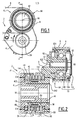
figure 1 is a front view of a belt tensioning device according to the invention; -
figure 2 is an enlarged cut view along line II-II onfigure 1 ; -
figure 3 is an exploded perspective view of the belt tensioning device offigures 1 and 2 ; -
figure 4 is a partially cut away view of detail IV onfigure 2 where a central portion of the receiver housing and a central portion of the lever arm are omitted, in order to show the position of a spring and a tooth; and -
figure 5 is a cut view similar tofigure 2 for a tensioning device according to a second embodiment of the invention. - The
belt tensioning device 2 represented onfigures 1 to 4 includes areceiver housing 4 adapted to be mounted on a crank case of a non-further represented internal combustion engine of an automotive vehicle. Thebelt tensioning device 2 also includes alever arm 6 which is pivotably mounted with respect toreceiver housing 4 around a first rotation axis X4 defined byreceiver housing 4. - Receiver housing can be mounted on a crank case by any known means, such as screws, bolts or rivets.
-
Lever arm 6 is equipped with apulley 8 made of a synthetic material which freely rotates around a second rotation axis X6 defined bylever arm 6 and parallel to axis X4. A ball bearing 10 supports thepulley 8 around acylindrical extension 62 oflever arm 6. Ball bearing 10 includes aninner ring 102 mounted aroundextension 62, anouter ring 104 mounted radially withinpulley 8 and a series ofballs 106 interposed between inner andouter rings screw 12 is inserted within a threadedhole 622 ofextension 62 and pushesinner ring 102 against ashoulder 624 ofextension 62, which immobilizesring 102 aroundextension 62.Pulley 8 is equipped with acap 82 which hidesbearing 10 andscrew 12 in the direction offigure 1 . - As shown in phantom lines on
figures 1 and 2 , a belt B can circulate around the outerperipheral surface 84 ofpulley 8, as well known for belt tensioning devices. - The angular position of
pulley 8 with respect to axis X4 impacts the tension of belt B. This angular position is determined by a torque T1 exerted by aspring 14 which belongs to belt tensioningdevice 2 and which is interposed betweenitems - More precisely,
receiver housing 4 forms acentral hub 42, aperipheral skirt 44 and anintermediate skirt 46, all centered on axis X4. An empty space S4 is defined, radially with respect to axis X4, betweenskirts spring 14. - On the other hand,
lever arm 6 includes acentral hub 64 and aperipheral skirt 66, both centered on axis X4. An empty space S6 is defined, radially with respect to axis X4, betweenitems spring 4. - Spaces S4 and S6 are annular and aligned along a direction parallel to axis X4. They have the same radial thickness. 48 denotes the bottom surface of empty space S4, that is an annular surface which is perpendicular to axis X4 and connects
skirts empty space 66 which is annular, perpendicular to axis X4 and connectshub 64 andskirt 66. - A first
terminal coil 142 ofspring 14 is fixedly connected tobottom surface 68. For instance, afree end 143 ofterminal coil 142 is anchored withinlever arm 6 or fixed by any other means on this part. Alternatively or in conjunction,coil 142 can be welded or glued to surface 68. Thus, whenlever arm 4 rotates around axis X4 with respect toreceiver housing 4,spring 4 also rotates around this axis. - 144 denotes the second terminal coil of
spring 14 which is opposite toterminal coil 142. 146 denotes the free end ofcoil 144. - The outer shape of
hub 64 is such that it is partially surrounded byintermediate skirt 46. A lining 16, which is made of an elastic material such as an elastomer, is fitted on the free end ofintermediate skirt 46, so thatspring 14 slides against someexternal ribs 162 of lining 16. The function of lining 16 is to avoid high amplitude vibrations ofspring 14 which could result from a resonance generated by the vibrations of the environment ofbelt tensioning unit 2. -
Hub 42 is provided with an outer peripheral threadedportion 422 which is centered on axis X4. On the other hand,hub 64 is provided with an inner threadedportion 642 also centered on axis X4. The geometry of threadedportions lever arm 6 can be screwed onreceiver housing 4 and unscrewed from this part, by rotatinglever arm 6 around axis X4 with respect toreceiver housing 4. - As shown on
figure 4 , aninclined tooth 50 protrudes fromsurface 48, so that it interacts withcoil 144 ofspring 14. In a direction orthoradial with respect to axis X4 and as shown onfigure 4 ,tooth 50 is defined between a slidingsurface 502 and a blockingsurface 504. Slidingsurface 502 extends along a direction Δ502 inclined with respect to axis X4. α denotes the angle between direction Δ502 and axis X4. The value of angle α is comprised between 5° and 85°, and preferably is appoximately 30°. This angle can vary on the basis of the characteristics ofspring 14. Blockingsurface 504 is parallel to axis X4, thus perpendicular to surface 48. - Upon screwing of
lever arm 6 onreceiver housing 4, theend 146 ofcoil 144 slides alongsurface 502, in the direction of arrow A1 onfigure 4 . Thus,tooth 50 allowsend 146 to go over it. - On the other hand, if one starts unscrewing
lever arm 6 with respect toreceiver housing 4, end 146 ofcoil 144 comes into abutment againstsurface 504, as shown by arrow A2, which induces thatend 146 is blocked in rotation with respect toreceiver housing 4. - During assembly of
belt tensioning unit 2,receiver housing 4 is prepared on one side andlever arm 6 is equipped withitems hub 64 is aligned on axis X4 and onescrews lever arm 6 onreceiver housing 4. This has no influence on the torque exerted byspring 14 onlever arm 6, since itsfree end 146, which is opposite to surface 68, slides ontooth 50 every 360°. In other words,spring 14 is not twisted by the screwing operation oflever arm 6 onreceiver housing 4. Because of this screwing movement, surfaces 48 and 68 come close together, which induces a compression ofspring 14. Thus,spring 14 exerts onitems 4 and 6 a compression effort E14 which is parallel to axis X4, that is axial, and which tends to spread these two parts apart in an axial direction. This effort E14 acts on threadedportions - Thus, effort E14 brakes a rotation of
lever arm 6 around axis X4. In other words, effort E14 has a damping effect on any rotational movement oflever arm 6 around axis X4. - In order to set the value of the torque T1 exerted by
spring 4, and oncelever arm 6 has been screwed onreceiver housing 4, one starts by unscrewinglever arm 6 up to a point whereend 146 comes into abutment againstsurface 504 oftooth 50. From this position, one further unscrewslever arm 6, which induces thatspring 14 is twisted and tightened, since its two ends are blocked, respectively with respect tolever arm 6 and with respect toreceiver housing 4. Thus, further unscrewing oflever arm 6 allows adjusting the intensity of torque T1. This further unscrewing movement also adjusts the intensity of effort E14, which is lowered, since the compression ofspring 14 betweensurfaces lever arm 6 with respect toreceiver housing 4 allows adjusting at the same time and in one operation, the intensity of torque T1 and the intensity of axial damping effort E14. - Effort E14 is a compression effort since it results from the compression of
spring 14 due to screwing oflever arm 6 onreceiver housing 4. Sinceterminal coils spring 14 lie againstsurfaces spring 14 anditems receiver housing 4 andlever arm 6 can be easily obtained by a casting operation. - The axial damping effort E14 has a direct influence on the torque T2 which is necessary to move
lever arm 6 with respect toreceiver housing 4 in the screwing direction. The following equation applies:
where ß is the pitch angle of the threadedportions parts - Pitch angle ß is related to the pitch P of the threads by the following relationship:

- On the other hand, the torque T3 necessary to rotate
lever arm 6 with respect to receivinghousing 4 in the unscrewing direction can be defined by the following relationship:
- Torque T2 and T3 are actually damping torques which resist any vibration movement of
lever arm 6 around axis X4. Because of the relationships of equations (1) and (3), it is possible to precisely adjust the values of T2 and T3 by a proper adjustment of axial effort E14. - In this first embodiment, threaded
portions hubs - In the second embodiment of the invention represented on
figure 5 , the elements equivalent to the ones of the first embodiment have the same references. Here-after, one describes only the differences with respect to the first embodiment. - In this second embodiment, a
synthetic sleeve 18 is incorporated, radially with respect to axis X4, betweenhubs portion 642 is provided radially insidehub 64, as in the first embodiment. On the other hand,sleeve 18 is rigidly attached tohub 42, e.g. by gluing, force-fitting, clipping or overmoldingand it is provided on its outer peripheral surface with a threadedportion 182, which works as threadedportion 422 of the first embodiment. This allows a precise machining of threadedportions receiver housing 4 is not easily machined. - For
instance sleeve 18 can be made of PA66. - According to a non-represented embodiment of the invention,
sleeve 18 can be rigidly mounted ontohub 64 and provided with an inner threaded portion, whereas a thread is provided on the outer peripheral surface ofhub 42. - According to still another embodiment of the invention, two sleeves can be provided and respectively secured to
hubs - In all embodiments,
items - Other modifications to the invention can be considered. For instance, several teeth equivalent to
tooth 50 can be distributed onsurface 48, around axis X4. Instead of being secured tolever arm 6,spring 14 can be secured toreceiver housing 4. In such a case, one or several stops similar totooth 50 are made onsurface 68, in order to interact withfree end 143 ofspring coil 142. - In another variant, angle α equals 90 and end 146 of
spring 14 jumps overthetooth 50 due to the coil shape ofspring 14. - The invention has been described in case it is used in conjunction with a belt B. However, it can also be used with a chain.
- The embodiments and alternative embodiments mentioned here-above can be combined in order to generate new embodiments of the invention.
Claims (15)
- A tensioning device (2) comprising:- a receiver housing (4),- a lever arm (6) mounted on the receiver housing and rotatable with respect to the receiver housing around a first rotation axis (X4),- a pulley (8) mounted on the lever arm and rotatable with respect to the lever arm around a second rotation axis (X6) parallel to the first rotation axis, and- a spring (14) mounted between the receiver housing and the lever arm and adapted to apply a torque (T1) for rotating the lever arm around the first rotation axis,characterized in that:- the receiver housing (4) and the lever arm (6) are screwed together around the first rotation axis (X4),- the spring (14) applies an axial damping effort (E14), parallel to the first axis, on cooperating threaded portions (462, 642 ; 182, 642) respectively provided on the receiver housing and on the lever arm.
- A tensioning device according to claim 1, characterized in that the axial effort (E14) is a compression effort exerted by the spring (14).
- A tensioning device according to claim 1 or 2, characterized in that a first end (142, 143) of the spring (14) is integral, in rotation around the first rotation axis (X4), with a first part (6) selected amongst the receiver housing (4) and the lever arm (6).
- A tensioning device according to claim 3, characterized in that a second part (4) selected between the receiver housing (4) and the lever arm (6) is provided with a stop (50) for a second end (146) of the spring (14).
- A tensioning device according to claim 4, characterized in that the stop (50) allows the second end (146) of the spring (14) to go over the stop (A1) upon screwing of the lever arm (6) on the receiver housing (4) and the stop blocks (A2) the second end of the spring upon unscrewing of the lever arm with respect to the receiver housing.
- A tensioning device according to claim 5, characterized in that in a direction orthoradial with respect to the first rotation axis (X4), the stop (50) includes a first surface (502) inclined (α) with respect to the first rotation axis, and a second surface (504) parallel to the first rotation axis.
- A tensioning device according to any preceding claim, characterized in that the threaded portions (422 ; 642) are directly formed on the receiver housing (4) and on the lever arm (6).
- A tensioning device according to one of claims 1 to 6, characterized in that at least one (182) of the threaded portions (182, 642) is formed on a sleeve (18) located between the receiver housing (4) and the lever arm (6) along a radial direction with respect to the first rotation axis (X4).
- A tensioning device according to claim 8, characterized in that the sleeve (18) is integral, in rotation around the first rotation axis (X4), with the receiver housing (4) and has a threaded portion (182) oriented radially towards the lever arm (6).
- A tensioning device according to claim 8, characterized in that the sleeve (18) is integral, in rotation around the first rotation axis (X4), with the lever arm (6) and has a threaded portion oriented radially towards the receiver housing (4).
- A tensioning device according to one of claims 8 to 10, characterized in that the sleeve (18) is made of a synthetic material, preferably of PA66.
- A tensioning device according to any preceding claim, characterized in that the receiver housing (4) and the lever arm (6) are made of aluminium or an aluminium based alloy.
- Method for assembling a tensioning device (2) according to any preceding claim, characterized in that it includes at least the following steps consisting in:- a) installing the spring (14) between the receiver housing (4) and the lever arm (6), and- b) screwing the lever arm and the receiver housing together.
- A method according to claim 13, characterized in that the tensioning device is according to claim 4 and the method includes at least the further steps consisting in:- c) fastening, in rotation around the first rotation axis (X4), the first end (142) of the spring (14) with the first part (6), and- d) after step b), unscrewing the lever arm (6) with respect to the receiver housing (4) and bringing the second end (146) of the spring (14) in abutment against the stop (50).
- A method according to claim 14, characterized in that it includes at least a further step consisting in:- e) after step d), further unscrewing the lever arm (6) with respect to the receiver housing (4) in order to generate the torque (T1) applied by the spring between the receiver housing and the lever arm and to adjust the value of the axial damping effort (E14).
Priority Applications (7)
| Application Number | Priority Date | Filing Date | Title |
|---|---|---|---|
| EP14305903.8A EP2955414A1 (en) | 2014-06-13 | 2014-06-13 | Tensioning device and method for assembling such a tensioning device |
| CA2894085A CA2894085A1 (en) | 2014-06-13 | 2015-06-08 | Tensioning device and method for assembling such a tensioning device |
| BR102015013758-3A BR102015013758A2 (en) | 2014-06-13 | 2015-06-11 | DEVICE AND METHOD FOR MOUNTING THAT DEVICE FOR TENSIONING |
| MX2015007468A MX2015007468A (en) | 2014-06-13 | 2015-06-11 | Tensioning device and method for assembling such a tensioning device. |
| US14/737,609 US9777807B2 (en) | 2014-06-13 | 2015-06-12 | Tensioning device and method for assembling such a tensioning device |
| JP2015119119A JP2016003767A (en) | 2014-06-13 | 2015-06-12 | Tension adjusting device and method for assembling the tension adjusting device |
| CN201510329133.8A CN105179618B (en) | 2014-06-13 | 2015-06-15 | The method of tensioning apparatus and this tensioning apparatus of assembly |
Applications Claiming Priority (1)
| Application Number | Priority Date | Filing Date | Title |
|---|---|---|---|
| EP14305903.8A EP2955414A1 (en) | 2014-06-13 | 2014-06-13 | Tensioning device and method for assembling such a tensioning device |
Publications (1)
| Publication Number | Publication Date |
|---|---|
| EP2955414A1 true EP2955414A1 (en) | 2015-12-16 |
Family
ID=51014249
Family Applications (1)
| Application Number | Title | Priority Date | Filing Date |
|---|---|---|---|
| EP14305903.8A Withdrawn EP2955414A1 (en) | 2014-06-13 | 2014-06-13 | Tensioning device and method for assembling such a tensioning device |
Country Status (7)
| Country | Link |
|---|---|
| US (1) | US9777807B2 (en) |
| EP (1) | EP2955414A1 (en) |
| JP (1) | JP2016003767A (en) |
| CN (1) | CN105179618B (en) |
| BR (1) | BR102015013758A2 (en) |
| CA (1) | CA2894085A1 (en) |
| MX (1) | MX2015007468A (en) |
Cited By (1)
| Publication number | Priority date | Publication date | Assignee | Title |
|---|---|---|---|---|
| CN115135906A (en) * | 2020-01-08 | 2022-09-30 | 盖茨公司 | Adjustable damping mechanism for tensioner device |
Families Citing this family (11)
| Publication number | Priority date | Publication date | Assignee | Title |
|---|---|---|---|---|
| ITTO20131032A1 (en) * | 2013-12-17 | 2015-06-18 | Dayco Europe Srl | TENSIONER FOR A BELT DRIVE |
| US9250272B2 (en) * | 2014-02-12 | 2016-02-02 | National Instruments Corporation | Low profile current measurement connector |
| DE102015212927A1 (en) * | 2015-07-10 | 2017-01-12 | Schaeffler Technologies AG & Co. KG | Pendulum clamp with adjustable axial play and belt drive |
| JP6613694B2 (en) * | 2015-08-04 | 2019-12-04 | ミツミ電機株式会社 | Actuator and electric hairdressing beauty instrument |
| US10859141B2 (en) * | 2015-10-28 | 2020-12-08 | Litens Automotive Partnership | Tensioner with first and second damping members and increased damping |
| US11168767B2 (en) * | 2018-10-23 | 2021-11-09 | Gates Corporation | Tensioner |
| JP7128956B2 (en) * | 2019-03-28 | 2022-08-31 | 本田技研工業株式会社 | tensioner lifter |
| CN110666079A (en) * | 2019-10-16 | 2020-01-10 | 杭州高品自动化设备有限公司 | Torsion tooling in torsion spring torsion structure |
| CN114483895A (en) * | 2020-11-13 | 2022-05-13 | 盖茨优霓塔传动系统(上海)有限公司 | Timing tensioner |
| WO2022182809A1 (en) * | 2021-02-26 | 2022-09-01 | Dayco Ip Holdings, Llc | High-offset belt tensioner with counterbalance torsion spring force |
| IT202100014756A1 (en) * | 2021-06-07 | 2022-12-07 | Dayco Europe Srl | TENSIONER WITH DOUBLE DAMPING SYSTEM FOR A TIMING BELT DRIVE |
Citations (7)
| Publication number | Priority date | Publication date | Assignee | Title |
|---|---|---|---|---|
| GB2258287A (en) * | 1991-07-31 | 1993-02-03 | Ntn Toyo Bearing Co Ltd | Belt tensioner adjusting device |
| DE19548435A1 (en) * | 1994-12-26 | 1996-06-27 | Aisin Seiki | Automatic belt tensioner, esp. with belt disc |
| US5772549A (en) | 1995-12-12 | 1998-06-30 | Muhr Und Bender | Belt tensioning device |
| US20060079360A1 (en) | 2004-09-28 | 2006-04-13 | Manfred Jung | Belt tensioning device with high damping rate |
| DE102005033056A1 (en) * | 2005-07-15 | 2007-01-25 | Schaeffler Kg | Mechanical damping system for chain and belt tensioner especially for IC engines has interlocking friction profiles for support arm mounting |
| DE102006014942A1 (en) * | 2006-03-31 | 2007-10-04 | Schaeffler Kg | Clamping device for use in traction mechanism drive, has coil spring, where tilting moment of spring force of spring and resultant reaction force of drive mutually suspend rotary axis of swivel bearing around imaginary slide tilting axis |
| US20080280713A1 (en) | 2005-10-31 | 2008-11-13 | Michael Fischer | Belt Tensioner |
Family Cites Families (62)
| Publication number | Priority date | Publication date | Assignee | Title |
|---|---|---|---|---|
| US4285676A (en) * | 1979-12-17 | 1981-08-25 | Dyneer Corporation | Mechanical belt tensioner construction |
| US4473362A (en) * | 1981-07-08 | 1984-09-25 | Litens Automotive Inc. | Belt tensioner with variably proportional damping |
| US4557709A (en) * | 1982-05-03 | 1985-12-10 | I Corp. | Belt tensioner system |
| US4464146A (en) * | 1982-05-17 | 1984-08-07 | Imperial Clevite Inc. | Apparatus for maintaining tension of an endless drive member |
| DE3716571C1 (en) * | 1987-05-18 | 1989-01-12 | Werner Kotzab | Tensioning device for belts and the like, in particular on motor vehicle engines |
| US5011460A (en) * | 1989-03-16 | 1991-04-30 | Nippon Seiko Kabushiki Kaisha | Belt tensioner with elastic damping feature |
| US4886484A (en) * | 1989-06-02 | 1989-12-12 | Litens Automotive Partnership | Torsional spring tensioner with stabilizer |
| US5234384A (en) * | 1990-09-29 | 1993-08-10 | Fujikiko Kabushiki Kaisha | Automatic tensioner |
| DE4242293A1 (en) * | 1991-12-18 | 1993-06-24 | Ntn Toyo Bearing Co Ltd | |
| US5190502A (en) * | 1992-02-07 | 1993-03-02 | Dayco Products, Inc. | Belt tensioning system, belt tensioner therefor and methods of making the same |
| DE4224759C2 (en) * | 1992-07-27 | 2002-04-18 | Ina Schaeffler Kg | Tensioning system, friction damped for belt or chain drives |
| US5277667A (en) * | 1992-09-18 | 1994-01-11 | Dayco Products, Inc. | Belt tensioning system and method of making |
| DE4426666A1 (en) * | 1994-07-28 | 1996-02-01 | Schaeffler Waelzlager Kg | Device for damping spring vibrations |
| DE4428560A1 (en) * | 1994-08-12 | 1996-02-15 | Schaeffler Waelzlager Kg | Tensioning device with lamellar form plane bearing ring |
| US5478285A (en) * | 1995-01-31 | 1995-12-26 | The Gates Rubber Company | Belt tensioner with pivot bushing damping |
| US5803849A (en) * | 1995-06-14 | 1998-09-08 | Unitta Company | Belt tensioner |
| ATE197498T1 (en) * | 1996-08-21 | 2000-11-11 | Tesma Int Inc | BELT TENSIONING DEVICE, PARTICULARLY FOR MOTOR VEHICLES |
| US5964674A (en) * | 1997-03-21 | 1999-10-12 | The Gates Corporation | Belt tensioner with bottom wall of base juxtaposed pivot arm |
| JPH1137232A (en) * | 1997-07-24 | 1999-02-12 | Honda Motor Co Ltd | Auto tensioner |
| JP2951321B1 (en) * | 1998-06-26 | 1999-09-20 | ユニッタ株式会社 | Auto tensioner |
| US6458055B1 (en) * | 1999-04-12 | 2002-10-01 | Litens Automotive | Reversible tensioner |
| DE29914381U1 (en) * | 1999-08-17 | 2000-03-02 | INA Wälzlager Schaeffler oHG, 91074 Herzogenaurach | Clamping device for a traction mechanism drive |
| DE19946057A1 (en) * | 1999-09-25 | 2001-03-29 | Schaeffler Waelzlager Ohg | Tightening unit for a traction drive element comprises a damping disk which is located between the friction lining of the friction disk and the housing of the unit |
| US6565468B2 (en) * | 1999-12-21 | 2003-05-20 | The Gates Corporation | Tensioner with damping mechanism |
| US6582332B2 (en) * | 2000-01-12 | 2003-06-24 | The Gates Corporation | Damping mechanism for a tensioner |
| JP2001241522A (en) * | 2000-02-25 | 2001-09-07 | Bando Chem Ind Ltd | Belt transmission |
| US6605013B2 (en) * | 2000-09-15 | 2003-08-12 | Litens Automotive Partnership | Belt tensioner combination and a method of installing a tensioner on a belt |
| US6575860B2 (en) * | 2001-02-28 | 2003-06-10 | Dayco Products, Llc | Belt tensioner for a power transmission belt system |
| US6609988B1 (en) * | 2001-05-24 | 2003-08-26 | The Gates Corporation | Asymmetric damping tensioner belt drive system |
| US6932731B2 (en) * | 2001-07-05 | 2005-08-23 | Ina-Schaeffler Kg | Tensioner |
| PL205953B1 (en) * | 2001-07-31 | 2010-06-30 | Litens Automotive Inc | Belt tensioner with installation pin |
| US6857979B2 (en) * | 2001-10-26 | 2005-02-22 | Litens Automotive Partnership | Combination belt tensioner and idler |
| CA2469497C (en) * | 2001-12-05 | 2010-07-20 | Litens Automotive | Timing belt tensioner with stops controlled by frictional brake |
| US6863631B2 (en) * | 2001-12-20 | 2005-03-08 | Dayco Products, Llc | Unidirectional motion asymmetric damped tensioner |
| US7004863B2 (en) * | 2002-05-15 | 2006-02-28 | The Gates Corporation | Damping mechanism |
| US7186196B2 (en) * | 2002-07-18 | 2007-03-06 | Dayco Products, Llc | Belt tensioner with integral damping |
| US7837582B2 (en) * | 2002-09-30 | 2010-11-23 | Fenner, Inc. | Bi-directional belt tensioner |
| DE10248352A1 (en) * | 2002-10-17 | 2004-04-29 | Ina-Schaeffler Kg | Clamping device for a traction mechanism drive |
| ITTO20030819A1 (en) * | 2003-10-17 | 2005-04-18 | Dayco Europe Srl | BI-ARM TENSIONER FOR A TRANSMISSION BELT OF A MOTOR VEHICLE. |
| DE20319886U1 (en) * | 2003-12-22 | 2005-05-04 | Litens Automotive Gmbh | Automatic belt tensioner |
| US7637829B2 (en) * | 2004-09-29 | 2009-12-29 | The Gates Corporation | Eccentric pivot arm tensioner |
| US7497794B2 (en) * | 2004-11-05 | 2009-03-03 | Dayco Products, Llc | Belt tensioner and method for assembly |
| US7887445B2 (en) * | 2005-01-20 | 2011-02-15 | Dayco Products, Llc | Belt tensioner |
| JP5242544B2 (en) * | 2006-03-22 | 2013-07-24 | ライテンズ オートモーティブ パートナーシップ | Flexible drive tensioner |
| DE102006017287B4 (en) * | 2006-04-12 | 2021-03-25 | Litens Automotive Gmbh | Tensioner for an endless drive |
| JP4922667B2 (en) * | 2006-05-30 | 2012-04-25 | 日産自動車株式会社 | Tensioner |
| PL2140172T3 (en) * | 2007-05-01 | 2012-01-31 | Litens Automotive Inc | Wear compensated tensioner |
| DE102007031298A1 (en) * | 2007-07-05 | 2009-01-08 | Schaeffler Kg | Damping device of a mechanical tensioning system for a traction mechanism drive |
| US7946938B2 (en) * | 2007-11-09 | 2011-05-24 | The Gates Corporation | Tensioner |
| US7803078B2 (en) * | 2008-03-20 | 2010-09-28 | The Gates Corporation | Tensioner |
| US8142315B2 (en) * | 2008-04-30 | 2012-03-27 | Litens Automotive Partnership | Tensioner with hub load balancing feature |
| US8784244B2 (en) * | 2008-04-30 | 2014-07-22 | Dayco Ip Holdings, Llc | Pulley with asymmetric torque-sensitive clutching |
| PL2331844T3 (en) * | 2008-10-02 | 2014-05-30 | Litens Automotive Inc | Compact tensioner with sustainable damping |
| US8092328B2 (en) * | 2009-06-30 | 2012-01-10 | The Gates Corporation | Dual tensioner assembly |
| US20110015017A1 (en) * | 2009-07-17 | 2011-01-20 | Alexander Serkh | Tensioner |
| US8613680B2 (en) * | 2010-04-20 | 2013-12-24 | Litens Automotive Partnership | Tensioner with spring damper |
| US8545352B2 (en) * | 2010-09-02 | 2013-10-01 | Dayco Ip Holdings, Llc | Tensioner with expanding spring for radial frictional asymmetric damping |
| US8617013B2 (en) * | 2010-09-02 | 2013-12-31 | Dayco Ip Holdings, Llc | Tensioner with expanding spring for radial frictional asymmetric damping |
| US20130217525A1 (en) * | 2012-02-17 | 2013-08-22 | Dayco Products, Llc | Belt tensioning device with locating pin |
| US9777806B2 (en) * | 2012-03-28 | 2017-10-03 | Dayco Ip Holdings, Llc | Sealed belt tensioning device |
| WO2014063228A1 (en) * | 2012-10-22 | 2014-05-01 | Litens Automotive Partnership | Tensioner with increased damping |
| CN103089945A (en) * | 2013-01-14 | 2013-05-08 | 上海贝尼汽车科技有限公司 | Belt tightening pulley for automobile engine |
-
2014
- 2014-06-13 EP EP14305903.8A patent/EP2955414A1/en not_active Withdrawn
-
2015
- 2015-06-08 CA CA2894085A patent/CA2894085A1/en not_active Abandoned
- 2015-06-11 MX MX2015007468A patent/MX2015007468A/en unknown
- 2015-06-11 BR BR102015013758-3A patent/BR102015013758A2/en not_active Application Discontinuation
- 2015-06-12 JP JP2015119119A patent/JP2016003767A/en active Pending
- 2015-06-12 US US14/737,609 patent/US9777807B2/en not_active Expired - Fee Related
- 2015-06-15 CN CN201510329133.8A patent/CN105179618B/en not_active Expired - Fee Related
Patent Citations (7)
| Publication number | Priority date | Publication date | Assignee | Title |
|---|---|---|---|---|
| GB2258287A (en) * | 1991-07-31 | 1993-02-03 | Ntn Toyo Bearing Co Ltd | Belt tensioner adjusting device |
| DE19548435A1 (en) * | 1994-12-26 | 1996-06-27 | Aisin Seiki | Automatic belt tensioner, esp. with belt disc |
| US5772549A (en) | 1995-12-12 | 1998-06-30 | Muhr Und Bender | Belt tensioning device |
| US20060079360A1 (en) | 2004-09-28 | 2006-04-13 | Manfred Jung | Belt tensioning device with high damping rate |
| DE102005033056A1 (en) * | 2005-07-15 | 2007-01-25 | Schaeffler Kg | Mechanical damping system for chain and belt tensioner especially for IC engines has interlocking friction profiles for support arm mounting |
| US20080280713A1 (en) | 2005-10-31 | 2008-11-13 | Michael Fischer | Belt Tensioner |
| DE102006014942A1 (en) * | 2006-03-31 | 2007-10-04 | Schaeffler Kg | Clamping device for use in traction mechanism drive, has coil spring, where tilting moment of spring force of spring and resultant reaction force of drive mutually suspend rotary axis of swivel bearing around imaginary slide tilting axis |
Cited By (2)
| Publication number | Priority date | Publication date | Assignee | Title |
|---|---|---|---|---|
| CN115135906A (en) * | 2020-01-08 | 2022-09-30 | 盖茨公司 | Adjustable damping mechanism for tensioner device |
| EP4088045B1 (en) * | 2020-01-08 | 2025-08-20 | Gates Corporation | Adjustable damping mechanism for tensioner device |
Also Published As
| Publication number | Publication date |
|---|---|
| US9777807B2 (en) | 2017-10-03 |
| JP2016003767A (en) | 2016-01-12 |
| MX2015007468A (en) | 2015-12-14 |
| CN105179618B (en) | 2019-07-23 |
| CA2894085A1 (en) | 2015-12-13 |
| CN105179618A (en) | 2015-12-23 |
| US20150362047A1 (en) | 2015-12-17 |
| BR102015013758A2 (en) | 2017-09-19 |
Similar Documents
| Publication | Publication Date | Title |
|---|---|---|
| US9777807B2 (en) | Tensioning device and method for assembling such a tensioning device | |
| KR100237231B1 (en) | Serpentine drive with coil spring unidirectional clutch alternator connection | |
| KR102347563B1 (en) | Torsional vibration dampers | |
| US8210950B2 (en) | Torque fluctuation absorbing apparatus | |
| US4983145A (en) | Apparatus for automatically tensioning a drive belt | |
| KR101643029B1 (en) | Pulley with asymmetric torque-sensitive clutching | |
| US6637570B2 (en) | Over-running clutch pulley with composite sealing member | |
| JPH06207525A (en) | Serpentine belt drive and alternator assembly for automobiles | |
| JPH09504353A (en) | Torsional vibration damping device | |
| US4084397A (en) | Arbor assembly for rotary mowers | |
| US12560206B2 (en) | Torque limiting coupler for an electric motor shaft | |
| KR20230098719A (en) | Isolating decoupler | |
| US9239097B2 (en) | Tensioning device for a traction element and method of installation of such a device | |
| US11981201B2 (en) | Accessory rotary drive system and method | |
| US6688986B2 (en) | Mounting structure for a cam-type torque damper | |
| EP1899621B1 (en) | Arrangement for damping vibrations on a driving wheel and driving wheel for an ancillary unit pulley of an internal combustion engine | |
| US6796413B2 (en) | One-way clutch | |
| CN109538733B (en) | A vibration damping pulley | |
| KR20040034739A (en) | Mounting of a flywheel of a clutch, supporting the rotor of a rotating electric machine, on the crankshaft of a vehicle engine | |
| US5165510A (en) | Centrifugal friction clutch | |
| CN114761703A (en) | Torsional vibration damper with torque limiting device | |
| DE102010005423B4 (en) | Pulley assembly for attachment to the crankshaft | |
| JP4277507B2 (en) | Torque fluctuation absorber | |
| JP6588529B2 (en) | Two-part hub for torsional vibration dampers and method for manufacturing the two-part hub | |
| JP5684272B2 (en) | Vibration damper device for drive system |
Legal Events
| Date | Code | Title | Description |
|---|---|---|---|
| PUAI | Public reference made under article 153(3) epc to a published international application that has entered the european phase |
Free format text: ORIGINAL CODE: 0009012 |
|
| AK | Designated contracting states |
Kind code of ref document: A1 Designated state(s): AL AT BE BG CH CY CZ DE DK EE ES FI FR GB GR HR HU IE IS IT LI LT LU LV MC MK MT NL NO PL PT RO RS SE SI SK SM TR |
|
| AX | Request for extension of the european patent |
Extension state: BA ME |
|
| 17P | Request for examination filed |
Effective date: 20160425 |
|
| RBV | Designated contracting states (corrected) |
Designated state(s): AL AT BE BG CH CY CZ DE DK EE ES FI FR GB GR HR HU IE IS IT LI LT LU LV MC MK MT NL NO PL PT RO RS SE SI SK SM TR |
|
| STAA | Information on the status of an ep patent application or granted ep patent |
Free format text: STATUS: EXAMINATION IS IN PROGRESS |
|
| 17Q | First examination report despatched |
Effective date: 20190523 |
|
| STAA | Information on the status of an ep patent application or granted ep patent |
Free format text: STATUS: THE APPLICATION IS DEEMED TO BE WITHDRAWN |
|
| 18D | Application deemed to be withdrawn |
Effective date: 20220104 |