EP2955396A1 - A bearing assembly with adjustment means - Google Patents
A bearing assembly with adjustment means Download PDFInfo
- Publication number
- EP2955396A1 EP2955396A1 EP15166713.6A EP15166713A EP2955396A1 EP 2955396 A1 EP2955396 A1 EP 2955396A1 EP 15166713 A EP15166713 A EP 15166713A EP 2955396 A1 EP2955396 A1 EP 2955396A1
- Authority
- EP
- European Patent Office
- Prior art keywords
- journal
- bearing assembly
- frusto
- rings
- conical contact
- Prior art date
- Legal status (The legal status is an assumption and is not a legal conclusion. Google has not performed a legal analysis and makes no representation as to the accuracy of the status listed.)
- Withdrawn
Links
Images

Classifications
-
- F—MECHANICAL ENGINEERING; LIGHTING; HEATING; WEAPONS; BLASTING
- F16—ENGINEERING ELEMENTS AND UNITS; GENERAL MEASURES FOR PRODUCING AND MAINTAINING EFFECTIVE FUNCTIONING OF MACHINES OR INSTALLATIONS; THERMAL INSULATION IN GENERAL
- F16C—SHAFTS; FLEXIBLE SHAFTS; ELEMENTS OR CRANKSHAFT MECHANISMS; ROTARY BODIES OTHER THAN GEARING ELEMENTS; BEARINGS
- F16C25/00—Bearings for exclusively rotary movement adjustable for wear or play
- F16C25/02—Sliding-contact bearings
-
- F—MECHANICAL ENGINEERING; LIGHTING; HEATING; WEAPONS; BLASTING
- F16—ENGINEERING ELEMENTS AND UNITS; GENERAL MEASURES FOR PRODUCING AND MAINTAINING EFFECTIVE FUNCTIONING OF MACHINES OR INSTALLATIONS; THERMAL INSULATION IN GENERAL
- F16C—SHAFTS; FLEXIBLE SHAFTS; ELEMENTS OR CRANKSHAFT MECHANISMS; ROTARY BODIES OTHER THAN GEARING ELEMENTS; BEARINGS
- F16C17/00—Sliding-contact bearings for exclusively rotary movement
- F16C17/02—Sliding-contact bearings for exclusively rotary movement for radial load only
-
- F—MECHANICAL ENGINEERING; LIGHTING; HEATING; WEAPONS; BLASTING
- F16—ENGINEERING ELEMENTS AND UNITS; GENERAL MEASURES FOR PRODUCING AND MAINTAINING EFFECTIVE FUNCTIONING OF MACHINES OR INSTALLATIONS; THERMAL INSULATION IN GENERAL
- F16C—SHAFTS; FLEXIBLE SHAFTS; ELEMENTS OR CRANKSHAFT MECHANISMS; ROTARY BODIES OTHER THAN GEARING ELEMENTS; BEARINGS
- F16C17/00—Sliding-contact bearings for exclusively rotary movement
- F16C17/12—Sliding-contact bearings for exclusively rotary movement characterised by features not related to the direction of the load
- F16C17/24—Sliding-contact bearings for exclusively rotary movement characterised by features not related to the direction of the load with devices affected by abnormal or undesired positions, e.g. for preventing overheating, for safety
- F16C17/246—Sliding-contact bearings for exclusively rotary movement characterised by features not related to the direction of the load with devices affected by abnormal or undesired positions, e.g. for preventing overheating, for safety related to wear, e.g. sensors for measuring wear
-
- F—MECHANICAL ENGINEERING; LIGHTING; HEATING; WEAPONS; BLASTING
- F16—ENGINEERING ELEMENTS AND UNITS; GENERAL MEASURES FOR PRODUCING AND MAINTAINING EFFECTIVE FUNCTIONING OF MACHINES OR INSTALLATIONS; THERMAL INSULATION IN GENERAL
- F16C—SHAFTS; FLEXIBLE SHAFTS; ELEMENTS OR CRANKSHAFT MECHANISMS; ROTARY BODIES OTHER THAN GEARING ELEMENTS; BEARINGS
- F16C17/00—Sliding-contact bearings for exclusively rotary movement
- F16C17/26—Systems consisting of a plurality of sliding-contact bearings
-
- F—MECHANICAL ENGINEERING; LIGHTING; HEATING; WEAPONS; BLASTING
- F16—ENGINEERING ELEMENTS AND UNITS; GENERAL MEASURES FOR PRODUCING AND MAINTAINING EFFECTIVE FUNCTIONING OF MACHINES OR INSTALLATIONS; THERMAL INSULATION IN GENERAL
- F16C—SHAFTS; FLEXIBLE SHAFTS; ELEMENTS OR CRANKSHAFT MECHANISMS; ROTARY BODIES OTHER THAN GEARING ELEMENTS; BEARINGS
- F16C41/00—Other accessories, e.g. devices integrated in the bearing not relating to the bearing function as such
-
- F—MECHANICAL ENGINEERING; LIGHTING; HEATING; WEAPONS; BLASTING
- F16—ENGINEERING ELEMENTS AND UNITS; GENERAL MEASURES FOR PRODUCING AND MAINTAINING EFFECTIVE FUNCTIONING OF MACHINES OR INSTALLATIONS; THERMAL INSULATION IN GENERAL
- F16C—SHAFTS; FLEXIBLE SHAFTS; ELEMENTS OR CRANKSHAFT MECHANISMS; ROTARY BODIES OTHER THAN GEARING ELEMENTS; BEARINGS
- F16C41/00—Other accessories, e.g. devices integrated in the bearing not relating to the bearing function as such
- F16C41/008—Identification means, e.g. markings, RFID-tags; Data transfer means
-
- F—MECHANICAL ENGINEERING; LIGHTING; HEATING; WEAPONS; BLASTING
- F16—ENGINEERING ELEMENTS AND UNITS; GENERAL MEASURES FOR PRODUCING AND MAINTAINING EFFECTIVE FUNCTIONING OF MACHINES OR INSTALLATIONS; THERMAL INSULATION IN GENERAL
- F16C—SHAFTS; FLEXIBLE SHAFTS; ELEMENTS OR CRANKSHAFT MECHANISMS; ROTARY BODIES OTHER THAN GEARING ELEMENTS; BEARINGS
- F16C2226/00—Joining parts; Fastening; Assembling or mounting parts
- F16C2226/10—Force connections, e.g. clamping
- F16C2226/16—Force connections, e.g. clamping by wedge action, e.g. by tapered or conical parts
Definitions
- the invention relates to a bearing for use in a wide variety of applications. Particularly, but not exclusively, the invention relates to self-lubricated bearings.
- Flanged bearings are well known. Bearings having conical contact surfaces for supporting both radial and axial loads are also known, such as that disclosed in US 2013/0341458 .
- wear of a bearing 20 can cause a clearance 15 to form between a loaded shaft 10 and the surface of the bearing 20.
- peak contact pressures can be much greater than the case in which no clearance 15 is present.
- the present invention seeks to tackle at least some of the problems associated with the prior art or at least to provide a commercially acceptable alternative solution thereto.
- the present invention provides for a bearing assembly comprising: an inner journal for supporting a shaft and having a frusto-conical contact surface facing radially outwardly; an outer journal surrounding at least part of the inner journal and having a frusto-conical contact surface which faces radially inwardly; and adjustment means for adjusting the axial location of the inner journal relative to the outer journal.
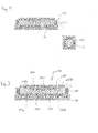
- Figure 2 shows a first embodiment of a bearing assembly.
- the bearing assembly comprises an inner journal 100 and an outer journal 200.
- the outer journal 200 surrounds at least part of the inner journal 100.
- the journals 100, 200 preferably comprise self-lubricating material.
- the inner journal 100 is arranged to be mounted on a shaft 10 and rotate therewith.
- the outer journal 200 can support other components relative to which the shaft 10 is rotated.
- the outer journal 200 can support a frame or housing. Thus, friction caused by rotation will be present between the contacting surfaces of the inner journal 100 and the outer journal 200.
- the inner journal 100 and the outer journal 200 have opposed and contacting frusto-conical contact surfaces 110, 210.
- the contact surface 110 of the inner journal 100 contacts the contact surface 210 of the outer journal 200.
- the inner journal 100 has a radially outward-facing frusto-conical contact surface 110.
- the outer journal 200 has a radially inward-facing frusto-conical contact surface 210.
- the inner and outer journals 100, 200 each have at least two frusto-conical contact surfaces 110, 210.
- the inner journal 100 or the outer journal 200 may be arranged to narrow towards its axially outermost ends to form a pair of frusto-conical contact surfaces 110a, 110b, 210a, 210b.
- the example of Figure 2 shows this arrangement for the outer journal 200.
- the inner journal 100 or the outer journal 200 may be arranged to widen towards its axially outermost ends to form a pair of frusto-conical contact surfaces 110a, 110b, 210a, 210b.
- the example of Figure 2 shows this arrangement for the inner journal 100.
- the contact surfaces 110, 210 of one of the inner and outer journals 100, 200 may be arranged to form a substantially triangular cross-section in an axial and radial plane.
- the contact surfaces 110, 210 of one of the inner and outer journals 100, 200 may be arranged to form a V-shaped cross-section in an axial and radial plane.
- One or both of the inner and outer journals 100, 200 are preferably formed from or comprise a self-lubricated material.
- the other preferably has a polished contact surface.
- One or both of the inner and outer journals 100, 200 may include a layer of self-lubricating material defining the contact surfaces 110, 210. It is unimportant whether the self-lubricated journal is the adjustable journal.
- One or both of the inner journal 100 and the outer journal 200 may comprise two or more parts 100a, 100b, 200a, 200b, with one frusto-conical contact surface 110a, 110b, 210a, 210b formed on each of the two parts.
- Such parts may be generally ring-shaped.
- the example of Figure 2 shows the inner journal 100 comprising two parts, which may slide axially relative to one another.
- the outer journal 200 may comprise: two parts having frusto-conical surfaces 210a, 210b; and a ring 250 of elastic material located therebetween.
- the ring 250 may be a separate entity or may be integrally formed with the two parts.
- an outer journal 200 may be used with an inner journal 100 in which the two parts 100a, 100b are joined to form a single body with a V-shaped cross-section.
- An indicator may be provided to show how far apart the two parts 200a, 200b have moved from their initial position.
- each of the two parts 200a, 200b may be marked, and the axial distance between the markings will vary as one or both of the journals 100, 200 wear.
- the shaft 10 rotates relative to a housing or other component (not shown).
- the inner journal 100 is mounted on the shaft so as to rotate therewith.
- the outer journal 200 is mounted on the housing or other component so as to rotate therewith, relative to the shaft 10.
- friction is developed between the contact surfaces 110, 210.
- the inventors have realised that owing to the frusto-conical shape of the contact surfaces 110, 210, the clearance between the inner and outer journals 100, 200, whilst formed by wear in the radial direction, may be taken up by adjusting the frusto-conical contact surfaces 110, 210 in the axial direction.
- Such adjustment of the inner and/or outer journals 100, 200 can reduce the consequences of journal wear, avoiding the situation depicted in Figure 1 for a longer period of time, and thus extend the useful life of the bearing.
- the rate of wear of the journals 100, 200 is reduced, because the peak contact pressures are reduced by taking up the clearance (thus avoiding the situation shown in Figure 1 ) thereby prolonging life of the bearing further.
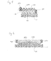
- this adjustment may be applied to a bearing having only a single frusto-conical contact 110, 210 surface on each of the inner and outer journals 100, 200 as shown in Figure 5 .
- the adjustment may be made by moving the frusto-conical surfaces 110a, 110b, 210a, 210b towards each other.
- the adjustment may be made by moving the frusto-conical surfaces 110a, 110b, 210a, 210b further apart.
- Such parts may form all or just part of the inner journal 100 or the outer journal 200.
- Adjustment means 150 for adjusting the axial location of the parts of the inner journal 100 relative to the outer journal 200 is shown in Figure 2 .
- a preferred adjustment means 150 may adjust the axial location of components of the inner member 100 along the shaft 10.
- Such adjustment means 150 may comprise an axially positionable member 152, such as a threaded member (e.g. a nut) engaging a thread on the shaft 10 or on a collar mounted on the shaft 10. Rotation of the threaded member 152 may translate it axially to abut and thereby move the frusto-conical part of the inner journal 100.
- An alternative axially positionable member 152 may be a ratchet. Such a ratchet may be arranged to allow axial translation of a frusto-conical contact surface 110, 210 in one direction only.
- the adjustment mechanism may include an opposing abutment 154, which may also be axially positionable member (which can allow accurate the bearing to be accurately centred) or may be axially fixed.
- the adjustment means 150 may be arranged (e.g. may be marked, or may cover a marking) to indicate the amount of movement of the inner journal 100 relative to the outer journal 200 (e.g. movement from their respective initial positions), and thereby indicate an amount of wear of the contact surfaces 110, 210.
- the amount of axial movement of an axially positionable member 152 can indicate an amount of wear of the contact surfaces 110, 210.
- the amount of rotation of a threaded member can indicate an amount of wear of the contact surfaces 110, 210.
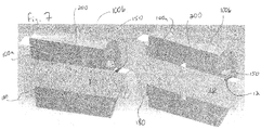
- Figure 7 shows two images demonstrating the axial movement of inner and outer journal components (in this case components 100b and 200, since component 100a abuts a fixed abutment 180) following adjustment using adjustment means 150.
- the adjustment means 150 conceals a marking on the shaft 10.
- the clearance may be taken up by adjusting the adjustment means 150 (e.g. rotating a bolt to axially translate along a threaded portion of the shaft 10).
- This adjustment moves one part 100b of the inner journal 100, and the outer journal 200, axially to take up the clearance.
- translation of the adjustment means 150 uncovers an indicator 12, which may be located on the shaft 10. In this way, when the indicator is fully uncovered, a user may choose to replace the bearing assembly.
- An alternative means for indicating an amount of axial movement may be provided electronically.
- electronic means for measuring axial displacement may be used to measure the relative axial movement of the parts of the inner and outer journals 100, 200.
- a strain gauge may be applied across the adjusted journal to measure movement.
- Such means for measuring axial displacement may preferably be arranged to provide a wireless signal.
- the adjustment means 250 for adjusting the axial location of the parts of the outer journal 200 relative to the inner journal 100 is shown.
- a ring 250 of elastic material may be located between the two separate rings 200a, 200b to collectively form part or all of the outer journal 200.
- the rings 200a, 200b and the ring 250 may be separate entities or may be adjoined or formed integrally.
- the ring 250 may be compressed so as to bias the two parts 200a, 200b outwardly.
- the two parts 200a, 200b of the outer journal 200 are free to slide axially apart under the force of the compressed ring 250, and thereby take up the clearance.
- the inner journal 100 is preferable for the inner journal 100 to be made of two separate parts. In which case, abutments 180 that cannot move axially along the shaft may be provided to prevent outward motion of the parts of the inner journal 100.
- FIG. 5 A further arrangement is shown in Figure 5 .
- the inner journal 100 of this embodiment has only a single frusto-conical contact surface 110 and the outer journal 200 has only a single frusto-conical contact surface 210.
- axial adjustment can remove any clearance between the contact surfaces 110, 210.
- the inner journal 100 can be adjusted by adjustment means 150 and/or the outer journal 200 can be adjusted by adjustment means 250.
- Figure 6 illustrates how the inner and outer journals 100, 200 may be arranged in the opposite manner from Figure 1 .
- the inner journal 100 may, optionally, comprise a compressive ring of material separating two parts.
- the inner journal 100 may simply be a solid piece of material having a substantially triangular cross-section.
Landscapes
- Engineering & Computer Science (AREA)
- General Engineering & Computer Science (AREA)
- Mechanical Engineering (AREA)
- Sliding-Contact Bearings (AREA)
- Support Of The Bearing (AREA)
Abstract
an inner journal for supporting a shaft (10) and arranged to rotate therewith, and having two frusto-conical contact surfaces (110a, 110b) facing radially outwardly;
an outer journal surrounding at least part of the inner journal and is arranged to rotate relative to the inner journal, and having two frusto-conical contact surfaces (210a, 210b) which face radially inwardly, wherein at least one of the inner journal and/or the outer journal comprises two rings (200a, 200b), each ring having a frusto-conical contact surface which tapers towards or away from the frusto-conical contact surface of the other ring; and
adjustment means (250) for adjusting the axial location of the inner journal relative to the outer journal.
Description
- The invention relates to a bearing for use in a wide variety of applications. Particularly, but not exclusively, the invention relates to self-lubricated bearings.
- Flanged bearings are well known. Bearings having conical contact surfaces for supporting both radial and axial loads are also known, such as that disclosed in
US 2013/0341458 . - As illustrated in
Figure 1 , wear of a bearing 20 (shown in cross-section) can cause aclearance 15 to form between a loadedshaft 10 and the surface of thebearing 20. When abearing 20 with such aclearance 15 is subjected to an oscillating load, peak contact pressures can be much greater than the case in which noclearance 15 is present. - The present invention seeks to tackle at least some of the problems associated with the prior art or at least to provide a commercially acceptable alternative solution thereto.
- The present invention provides for a bearing assembly comprising: an inner journal for supporting a shaft and having a frusto-conical contact surface facing radially outwardly; an outer journal surrounding at least part of the inner journal and having a frusto-conical contact surface which faces radially inwardly; and adjustment means for adjusting the axial location of the inner journal relative to the outer journal.
- For a better understanding of the invention and to show how the same may be put into effect, reference will now be made, by way of example only, to the appended drawings, in which:
-
Figure 1 schematically represents the problems of a clearance formed between a loaded shaft and a bearing surface when subjected to oscillating loading; -
Figure 2 shows a first embodiment of a bearing in accordance with the invention; -
Figure 3 shows a second embodiment of a bearing in accordance with the invention; -
Figure 4 shows a preferred variant of the first embodiment; -
Figure 5 shows an alternative embodiment of a bearing; -
Figure 6 shows an alternative embodiment of a bearing; and -
Figure 7 shows a cut-away perspective view demonstrating a preferred indicator for indicating an amount of wear of the journals. - Each aspect or embodiment as defined herein may be combined with any other aspect(s) or embodiment(s) unless clearly indicated to the contrary. In particular, any features indicated as being preferred or advantageous may be combined with any other feature indicated as being preferred or advantageous.
-
Figure 2 shows a first embodiment of a bearing assembly. The bearing assembly comprises aninner journal 100 and anouter journal 200. Theouter journal 200 surrounds at least part of theinner journal 100. - The
journals - The
inner journal 100 is arranged to be mounted on ashaft 10 and rotate therewith. Theouter journal 200 can support other components relative to which theshaft 10 is rotated. For example, theouter journal 200 can support a frame or housing. Thus, friction caused by rotation will be present between the contacting surfaces of theinner journal 100 and theouter journal 200. - The
inner journal 100 and theouter journal 200 have opposed and contacting frusto-conical contact surfaces contact surface 110 of theinner journal 100 contacts thecontact surface 210 of theouter journal 200. - The
inner journal 100 has a radially outward-facing frusto-conical contact surface 110. Theouter journal 200 has a radially inward-facing frusto-conical contact surface 210. - Preferably, and as shown in
Figure 2 , the inner andouter journals conical contact surfaces - For example, the
inner journal 100 or theouter journal 200 may be arranged to narrow towards its axially outermost ends to form a pair of frusto-conical contact surfaces Figure 2 shows this arrangement for theouter journal 200. - In an alternative example, the
inner journal 100 or theouter journal 200 may be arranged to widen towards its axially outermost ends to form a pair of frusto-conical contact surfaces Figure 2 shows this arrangement for theinner journal 100. - The
contact surfaces outer journals contact surfaces outer journals - One or both of the inner and
outer journals outer journals - One or both of the inner and
outer journals contact surfaces - One or both of the
inner journal 100 and theouter journal 200 may comprise two ormore parts conical contact surface Figure 2 shows theinner journal 100 comprising two parts, which may slide axially relative to one another. - Similarly, the example of
Figure 3 shows theouter journal 200 may comprise: two parts having frusto-conical surfaces ring 250 of elastic material located therebetween. In alternative embodiments, thering 250 may be a separate entity or may be integrally formed with the two parts. Similarly, anouter journal 200 may be used with aninner journal 100 in which the twoparts - An indicator may be provided to show how far apart the two parts 200a, 200b have moved from their initial position. For example, each of the two parts 200a, 200b may be marked, and the axial distance between the markings will vary as one or both of the
journals - In use, the
shaft 10 rotates relative to a housing or other component (not shown). Theinner journal 100 is mounted on the shaft so as to rotate therewith. Theouter journal 200 is mounted on the housing or other component so as to rotate therewith, relative to theshaft 10. Thus, friction is developed between thecontact surfaces - After extended use and under transverse loading, wear of the inner and/or
outer journals opposing contact surfaces - The inventors have realised that owing to the frusto-conical shape of the
contact surfaces outer journals conical contact surfaces - This is demonstrated in
Figure 2 , in which wear imposed on the inner and/orouter journal Figure 2 is taken up by moving the twoinner journal 100 parts towards one another until the clearance is taken up as shown in the right half ofFigure 2 . - Such adjustment of the inner and/or
outer journals Figure 1 for a longer period of time, and thus extend the useful life of the bearing. - Moreover, the rate of wear of the
journals Figure 1 ) thereby prolonging life of the bearing further. - As will be appreciated, this adjustment may be applied to a bearing having only a single frusto-
conical contact outer journals Figure 5 . - When a
journal conical surfaces - Conversely, when a
journal conical surfaces - Such parts may form all or just part of the
inner journal 100 or theouter journal 200. - Adjustment means 150 for adjusting the axial location of the parts of the
inner journal 100 relative to theouter journal 200 is shown inFigure 2 . - As shown in
Figure 4 , a preferred adjustment means 150 may adjust the axial location of components of theinner member 100 along theshaft 10. Such adjustment means 150 may comprise an axiallypositionable member 152, such as a threaded member (e.g. a nut) engaging a thread on theshaft 10 or on a collar mounted on theshaft 10. Rotation of the threadedmember 152 may translate it axially to abut and thereby move the frusto-conical part of theinner journal 100. - An alternative axially
positionable member 152 may be a ratchet. Such a ratchet may be arranged to allow axial translation of a frusto-conical contact surface - In some embodiments, the adjustment mechanism may include an opposing abutment 154, which may also be axially positionable member (which can allow accurate the bearing to be accurately centred) or may be axially fixed.
- Advantageously, the adjustment means 150 may be arranged (e.g. may be marked, or may cover a marking) to indicate the amount of movement of the
inner journal 100 relative to the outer journal 200 (e.g. movement from their respective initial positions), and thereby indicate an amount of wear of the contact surfaces 110, 210. - For example, the amount of axial movement of an axially
positionable member 152 can indicate an amount of wear of the contact surfaces 110, 210. - Similarly, the amount of rotation of a threaded member can indicate an amount of wear of the contact surfaces 110, 210.
-
Figure 7 shows two images demonstrating the axial movement of inner and outer journal components (in thiscase components component 100a abuts a fixed abutment 180) following adjustment using adjustment means 150. In the initial position (the right-hand image), the adjustment means 150 conceals a marking on theshaft 10. As the inner and/orouter journals part 100b of theinner journal 100, and theouter journal 200, axially to take up the clearance. Advantageously, translation of the adjustment means 150 uncovers an indicator 12, which may be located on theshaft 10. In this way, when the indicator is fully uncovered, a user may choose to replace the bearing assembly. - An alternative means for indicating an amount of axial movement may be provided electronically.
- In such an embodiment, electronic means for measuring axial displacement may be used to measure the relative axial movement of the parts of the inner and
outer journals - This can allow wear to be monitored without disassembly of the device in which the bearing assembly is used. Such means for measuring axial displacement may preferably be arranged to provide a wireless signal.
- In the alternative embodiment of
Figure 3 , the adjustment means 250 for adjusting the axial location of the parts of theouter journal 200 relative to theinner journal 100 is shown. In this example, aring 250 of elastic material may be located between the two separate rings 200a, 200b to collectively form part or all of theouter journal 200. - The rings 200a, 200b and the
ring 250 may be separate entities or may be adjoined or formed integrally. - In the unworn state of the bearing, the
ring 250 may be compressed so as to bias the two parts 200a, 200b outwardly. As thejournals outer journal 200 are free to slide axially apart under the force of thecompressed ring 250, and thereby take up the clearance. - For ease of manufacture, it is preferable for the
inner journal 100 to be made of two separate parts. In which case,abutments 180 that cannot move axially along the shaft may be provided to prevent outward motion of the parts of theinner journal 100. - A further arrangement is shown in
Figure 5 . Theinner journal 100 of this embodiment has only a single frusto-conical contact surface 110 and theouter journal 200 has only a single frusto-conical contact surface 210. However, as can be seen from the Figure, axial adjustment can remove any clearance between the contact surfaces 110, 210. Theinner journal 100 can be adjusted by adjustment means 150 and/or theouter journal 200 can be adjusted by adjustment means 250. -
Figure 6 illustrates how the inner andouter journals Figure 1 . In the depicted arrangement, theinner journal 100 may, optionally, comprise a compressive ring of material separating two parts. Alternatively, theinner journal 100 may simply be a solid piece of material having a substantially triangular cross-section. - The foregoing detailed description has been provided by way of explanation and illustration, and is not intended to limit the scope of the appended claims. Many variations in the presently preferred embodiments illustrated herein will be apparent to one of ordinary skill in the art, and remain within the scope of the appended claims and their equivalents.
Claims (14)
- A bearing assembly comprising:an inner journal (100) for supporting a shaft (10) and arranged to rotate therewith, and having two frusto-conical contact surfaces (110a, 110b) facing radially outwardly;an outer journal (200) surrounding at least part of the inner journal and arranged to rotate relative to the inner journal, and having two frusto-conical contact surfaces (210a, 210b) which face radially inwardly, wherein at least one of the inner journal and/or the outer journal comprises two rings (100a, 100b, 200a, 200b), each ring having a frusto-conical contact surface which tapers towards or away from the frusto-conical contact surface of the other ring; andadjustment means (150, 250) for adjusting the axial location of the inner journal relative to the outer journal.
- The bearing assembly of claim 1, wherein the adjustment means comprises an axially positionable member (150) arranged to abut one of the inner journal (100) or the outer journal (200).
- The bearing assembly of claim 1 or claim 2, wherein the adjustment means comprises one or more of: a spring; a compressible material; a ratchet; and/or interlocking threaded members.
- The bearing assembly of claim 1, wherein the two rings (100a, 100b) are oriented such that their narrowest ends face each other.
- The bearing assembly of claim 4, wherein the adjustment means comprises one or more of a compressible material; a spring; a ratchet; and/or interlocking threaded members, and is located either side the two rings to thereby prevent the two rings from moving apart.
- The bearing assembly of any one of claim 1, wherein:the two rings (200a, 200b) are oriented such that their widest ends face towards each other.
- The bearing assembly of claim 6, wherein the adjustment means (250) comprises one or more of: a spring; and/or a compressible material, and is located between the two rings to thereby bias the two rings apart.
- The bearing assembly of any one of claims 1 to 7, comprising means for indicating an amount of relative axial movement between the two rings.
- The bearing assembly of any preceding claim, comprising means for indicating an amount of relative axial movement between the inner and outer journal.
- The bearing assembly of claim 8 or claim 9, wherein the adjustment means comprises interlocking threaded members, and the indicator indicates an amount of rotation of one of the interlocking threaded members.
- The bearing assembly of claim 8 or claim 9, wherein the means for indicating an amount of relative axial movement is an electronic device.
- The bearing assembly of claim 11, wherein the electronic device is arranged to provide a wireless signal.
- A method of maintaining a bearing that comprises an inner journal having a frusto-conical contact surface which faces radially outwardly and an outer journal surrounding at least part of the inner journal and having a frusto-conical contact surface which faces radially inwardly,
the method comprising varying the axial location of the inner journal relative to the outer journal until the frusto-conical contact surfaces abut. - The method of claim 13, further comprising electronically monitoring the axial movement of the inner journal relative to the outer journal.
Applications Claiming Priority (1)
| Application Number | Priority Date | Filing Date | Title |
|---|---|---|---|
| GBGB1410555.5A GB201410555D0 (en) | 2014-06-13 | 2014-06-13 | A bearing |
Publications (1)
| Publication Number | Publication Date |
|---|---|
| EP2955396A1 true EP2955396A1 (en) | 2015-12-16 |
Family
ID=51266543
Family Applications (1)
| Application Number | Title | Priority Date | Filing Date |
|---|---|---|---|
| EP15166713.6A Withdrawn EP2955396A1 (en) | 2014-06-13 | 2015-05-07 | A bearing assembly with adjustment means |
Country Status (3)
| Country | Link |
|---|---|
| US (1) | US9644673B2 (en) |
| EP (1) | EP2955396A1 (en) |
| GB (1) | GB201410555D0 (en) |
Families Citing this family (3)
| Publication number | Priority date | Publication date | Assignee | Title |
|---|---|---|---|---|
| CN110594289B (en) * | 2019-09-23 | 2020-04-14 | 中国石油天然气集团有限公司 | Bearing for rotary guiding tool and manufacturing method of wear-resistant teeth of bearing |
| CN117674709B (en) * | 2023-11-30 | 2025-08-22 | 天合光能股份有限公司 | Damping bearings and tracking brackets |
| US12601405B2 (en) * | 2024-06-27 | 2026-04-14 | Fisher Controls International Llc | Rotary bearing maintenance indication |
Citations (9)
| Publication number | Priority date | Publication date | Assignee | Title |
|---|---|---|---|---|
| CH281535A (en) * | 1950-01-07 | 1952-03-15 | Keller Friedrich | Ring plain bearings. |
| US3044798A (en) * | 1959-03-06 | 1962-07-17 | Theodore C Gerner | Replacement unit for idler arm bracket |
| US3701912A (en) * | 1971-11-08 | 1972-10-31 | Gerhard Schulze | Fan motor bearing assembly |
| GB1383157A (en) * | 1973-03-23 | 1975-02-05 | Skf Cie Applic Mecanique | Shaft bearing arrangement |
| EP0285453A2 (en) * | 1987-04-03 | 1988-10-05 | Everett Harrow Schwartzman | Improved resiliently mounted fluid bearing assembly |
| US5689146A (en) * | 1996-11-05 | 1997-11-18 | Synektron Corporation | Conical bearing system for spindle motors |
| US20030030565A1 (en) * | 2001-08-07 | 2003-02-13 | Nsk Ltd. | Wireless sensor, rolling bearing with sensor, management apparatus and monitoring system |
| EP1347184A1 (en) * | 2002-03-12 | 2003-09-24 | Buffalo Pumps, Inc. | Rotary pump with bearing wear indicator |
| EP1369593A2 (en) * | 2002-06-05 | 2003-12-10 | Buffalo Pumps, Inc. | Rotary pump with bearing wear indicator |
Family Cites Families (5)
| Publication number | Priority date | Publication date | Assignee | Title |
|---|---|---|---|---|
| US2147883A (en) * | 1937-03-15 | 1939-02-21 | Quinten E Conner | Expanding bearing pin |
| CH520283A (en) | 1970-05-22 | 1972-03-15 | Neukomm Walter | Plain bearing with axial and radial play that can be adjusted together |
| CH651896A5 (en) | 1981-02-16 | 1985-10-15 | Luwa Ag | RADIAL SLIDING BEARING ARRANGEMENT. |
| GB8805124D0 (en) | 1988-03-03 | 1988-03-30 | Blair George Plc | Improved self-adjusting bearing |
| US8745875B1 (en) * | 2012-11-26 | 2014-06-10 | George A. Hagelthorn | Ultrahigh-integrity interlocking nut and washer system for trailer axles |
-
2014
- 2014-06-13 GB GBGB1410555.5A patent/GB201410555D0/en not_active Ceased
-
2015
- 2015-05-07 EP EP15166713.6A patent/EP2955396A1/en not_active Withdrawn
- 2015-06-15 US US14/739,310 patent/US9644673B2/en active Active
Patent Citations (9)
| Publication number | Priority date | Publication date | Assignee | Title |
|---|---|---|---|---|
| CH281535A (en) * | 1950-01-07 | 1952-03-15 | Keller Friedrich | Ring plain bearings. |
| US3044798A (en) * | 1959-03-06 | 1962-07-17 | Theodore C Gerner | Replacement unit for idler arm bracket |
| US3701912A (en) * | 1971-11-08 | 1972-10-31 | Gerhard Schulze | Fan motor bearing assembly |
| GB1383157A (en) * | 1973-03-23 | 1975-02-05 | Skf Cie Applic Mecanique | Shaft bearing arrangement |
| EP0285453A2 (en) * | 1987-04-03 | 1988-10-05 | Everett Harrow Schwartzman | Improved resiliently mounted fluid bearing assembly |
| US5689146A (en) * | 1996-11-05 | 1997-11-18 | Synektron Corporation | Conical bearing system for spindle motors |
| US20030030565A1 (en) * | 2001-08-07 | 2003-02-13 | Nsk Ltd. | Wireless sensor, rolling bearing with sensor, management apparatus and monitoring system |
| EP1347184A1 (en) * | 2002-03-12 | 2003-09-24 | Buffalo Pumps, Inc. | Rotary pump with bearing wear indicator |
| EP1369593A2 (en) * | 2002-06-05 | 2003-12-10 | Buffalo Pumps, Inc. | Rotary pump with bearing wear indicator |
Also Published As
| Publication number | Publication date |
|---|---|
| US20150362011A1 (en) | 2015-12-17 |
| US9644673B2 (en) | 2017-05-09 |
| GB201410555D0 (en) | 2014-07-30 |
Similar Documents
| Publication | Publication Date | Title |
|---|---|---|
| CN103459867B (en) | Bridge Spring Centering Device and Damper Film Bearing Assembly for Compressed Film Dampers | |
| KR102263077B1 (en) | Rolling-element bearing | |
| US9644673B2 (en) | Bearing | |
| US10151342B2 (en) | Rolling bearing arrangement having a strain sensor device | |
| US20230003303A1 (en) | Abradable seal | |
| US20170146066A1 (en) | Dynamically aligning, maintenance free, radial insert ball bearing | |
| JP6934409B2 (en) | Bearing equipment and rotating machinery | |
| US1649258A (en) | Shaft bearing | |
| CA2946250C (en) | Linear bearing | |
| US3075632A (en) | Flexible and resilient mounting of troughing idler rollers for conveyor belts | |
| JP2019020359A (en) | Detection mechanism | |
| US4165636A (en) | Method and means for measuring preloads in assembled mechanisms | |
| US1817160A (en) | Self tightening bearing | |
| US4765755A (en) | Roller mill | |
| US2716033A (en) | Pivotal joint utilizing an end play take-up washer | |
| US2857765A (en) | Rotatable mechanical device | |
| RU2506468C1 (en) | Radial-axial sliding bearing | |
| US3471206A (en) | Shaft bearings for counterrotating propeller shafts | |
| RU2268412C1 (en) | Bearing unit | |
| JPH095151A (en) | Knife ring fittings | |
| RU2551771C1 (en) | Radial-axial sliding bearing | |
| US20140003748A1 (en) | Self-adjusting bushing bearing | |
| US1250620A (en) | Roller-bearing. | |
| RU2502897C1 (en) | Radial-axial plain bearing | |
| US496347A (en) | Journal-bearing |
Legal Events
| Date | Code | Title | Description |
|---|---|---|---|
| PUAI | Public reference made under article 153(3) epc to a published international application that has entered the european phase |
Free format text: ORIGINAL CODE: 0009012 |
|
| AK | Designated contracting states |
Kind code of ref document: A1 Designated state(s): AL AT BE BG CH CY CZ DE DK EE ES FI FR GB GR HR HU IE IS IT LI LT LU LV MC MK MT NL NO PL PT RO RS SE SI SK SM TR |
|
| AX | Request for extension of the european patent |
Extension state: BA ME |
|
| 17P | Request for examination filed |
Effective date: 20160606 |
|
| RBV | Designated contracting states (corrected) |
Designated state(s): AL AT BE BG CH CY CZ DE DK EE ES FI FR GB GR HR HU IE IS IT LI LT LU LV MC MK MT NL NO PL PT RO RS SE SI SK SM TR |
|
| 17Q | First examination report despatched |
Effective date: 20170420 |
|
| STAA | Information on the status of an ep patent application or granted ep patent |
Free format text: STATUS: THE APPLICATION IS DEEMED TO BE WITHDRAWN |
|
| 18D | Application deemed to be withdrawn |
Effective date: 20170831 |